CE6304-SURVEYING-I UNIT-I INTRODUCTION AND CHAIN … · CE6304-SURVEYING-I UNIT-I INTRODUCTION AND...
64
CE6304-SURVEYING-I UNIT-I INTRODUCTION AND CHAIN SURVEYING DEFINITION: Surveying is the art of determining the relative positions of points on, above or beneath the surface of the earth by means of direct or indirect measurements of distance, direction & elevation. Plane Survey: Surveying which the mean surface of earth regarded as plain surface and not curve it really is known as plain surveying. A following Assumption are made: (i) A level line is considered a strait line thus the plump line at a point is parallel plump line at any after point. (ii) The angles between two such lines that intersect is a plain angle and not a sphere angle. (iii) The meridian through any two points parallel. (iv) When we deal with only a small portion earths surface the above assumptions can justify. (v) The error induced for a length of an 18.5 kms it‘s only 0.0152 ms grater than sub dented chord 1.52 cm. Geodetic survey : Survey is which the shape (curvature) of the earth surface is taken in the account a higher degree of precision is exercised in linear and angular measurement is tanned as Geodetic Survey. A line connecting two points is regarded as an arc. Such surveys extend over large areas PRINCIPLES OF SURVEYING Location of a point by measurement from 2 points of reference Working from whole to part. Location of a point by measurement from 2 points of reference There should be 2 points of reference say P & Q P,Q are the ground reference points and permanent points. Point R can be located by any one of the following direct methgods: Distance PR and QR can be measured and point R can be plotted by swinging the Two arcs of the same scale to which PQ has been plotted. The principle is very much used in chain surveying. Perpendicular RS can be dropped on the reference line PQ and the lengths PS and SR are measured. The point R can be plotted using this set square. This principle is used for defining details. The distance QR & the angle PQR can be measured and point R is plotted either by means of protractor or trigonometrically. The principle is used in traversing.
Transcript of CE6304-SURVEYING-I UNIT-I INTRODUCTION AND CHAIN … · CE6304-SURVEYING-I UNIT-I INTRODUCTION AND...

CE6304-SURVEYING-I
UNIT-I
INTRODUCTION AND CHAIN SURVEYING
DEFINITION:
Surveying is the art of determining the relative positions of points on, above or beneath
the surface of the earth by means of direct or indirect measurements of distance, direction &
elevation.
Plane Survey:
Surveying which the mean surface of earth regarded as plain surface and not
curve it really is known as plain surveying.
A following Assumption are made:
(i) A level line is considered a strait line thus the plump line at a point is parallel plump line at
any after point.
(ii) The angles between two such lines that intersect is a plain angle and not a sphere angle.
(iii) The meridian through any two points parallel.
(iv) When we deal with only a small portion earths surface the above assumptions can justify.
(v) The error induced for a length of an 18.5 kms it‘s only 0.0152 ms grater than sub dented
chord 1.52 cm.
Geodetic survey :
Survey is which the shape (curvature) of the earth surface is taken in the account a
higher degree of precision is exercised in linear and angular measurement is tanned as Geodetic
Survey. A line connecting two points is regarded as an arc. Such surveys extend over large areas
PRINCIPLES OF SURVEYING
Location of a point by measurement from 2 points of reference
Working from whole to part.
Location of a point by measurement from 2 points of reference
There should be 2 points of reference say P & Q P,Q are the ground reference points and
permanent points. Point R can be located by any one of the following direct methgods:
Distance PR and QR can be measured and point R can be plotted by swinging the Two
arcs of the same scale to which PQ has been plotted. The principle is very much used in
chain surveying.
Perpendicular RS can be dropped on the reference line PQ and the lengths PS and SR are
measured. The point R can be plotted using this set square. This principle is used for
defining details.
The distance QR & the angle PQR can be measured and point R is plotted either by
means of protractor or trigonometrically. The principle is used in traversing.

In this distance PR and QR are not measured but angle RPQ are measured with an angle
measuring instrument. Knowing the distance PQ point R is plotted either by means of
protrctor or by solution of triangle PQR. This principle is used in triangulation.
Angle RQP & distance PR are measured & point R is plotted either by protracting an
angle & swinging an arc from P or plotted trigonometrically.
Working from whole to part.
First establish a system of control points & to fix them with higher precision.
Minor control points can then be established by less precise methods & the details can
then be located using these minor control points by running minor traverse etc.,
This method followed to prevent t the accumulation of errors & to control & localize
minor errors.
CLASSIFICATION
(a)Classification based upon the nature of survey of field survey:
(1) Land surveying
Topographical surveys
Cadastral surveys
City surveying
Topographical surveys: This consists of horizontal & vertical location of certain points by
linear & angular measurements. To determine natural features of a country such as rivers,
railways, canals, towns & villages.
Cadastral surveys: Fixing of property lines, calculation of land area or transfer of land property
from one owner to another. To fix boundaries of municipalities & of state & federal jurisdictions.
City surveying: construction of streets, water supply system sewers & other works.
(2) Marine/ Hydrographic survey:
Bodies of water for purpose of navigation, water supply, harbour works or for
determination of mean sea level. Measurement of discharge of streams, making topographic of
shores & banks, taking& locating soundings to determine depth of water, fluctuations of the
ocean tide.
(3) Astronomical survey:
To determine absolute location of any point & direction of any line on the surface of the
earth.
(b) Classification based on the object of survey :
(1) Engineering survey:
Determination of quantities or to afford sufficient data for the designing of engineering
works such as road s& reservoirs, also sewage disposal or water supply.
(2) Military survey:
Points of strategic importance.
(3) Mine Survey:
Exploring mineral wealth

(4) Geological Survey:
Different strata in the earth‘ s crust
(5) Archaeological survey:
Unearthing relics of antiquity.
( c) Classification based on instrument used:
1) Chain survey
2) Theodolite survey
3) Triangular survey
4) Triangulation survey
5) Tacheometric survey
6) Plane table survey
7) Photographic survey
8) Aerial survey
Field work & office work:
Field work:
1. Establishing stations & bench marks of points of reference & thus to establish a system of
horizontal & vertical control.
2. Measuring distance along the angles between the survey lines.
3. Locating details of survey with respect to stations & lines between stations, details such as
boundary lines, streets, roads, buildings, streams, bridges & other natural & artificial features of
area surveyed.
4. Giving lines & elevations for great variety of construction work such as that for buildings,
boundaries, roads, culverts, bridges, sewers & water supply schemes.
5. Determining elevations of some existing points or establishing points @ given elevations.
6. Surveying contours of land areas in which the field work involve both horizontal & vertical
control.
7. Carrying out miscellaneous operations such as, establishing parallel lines & perpendicular
lines
8. Taking measurements to inaccessible points.
9.Surveying past the obstacles, & carrying on a great variety of similar field work that is based
on geometric or trigonometric principles.
10. Making observations on the sun or a star to determine the meridian lartitude or longitude or
to determine the local time.
FIELD NOTES
1. Field notes are written records of field work made @ the time of work is done.
2. field notes should be legible, concise & comprehensive, written in clear, plain letters &
figures.
Rules for note-keepers:
o Record directly in the field book as observations are made.
o Use a sharp 2H or 3H pencil. Never use soft pencil or ink.

o Follow a consistent simple style of writing.
o Use a liberal number of carefully executed sketches.
o Make the notes for each day‘ s work on the survey complete with a title of the
survey, date, weather conditions, personnel of the crew, & list of equipment used.
o Never erase. If a mistake is made, rule one line through the incorrect value and
the correction above the mistake.
o Sign the notes
Field notes divided into 3 parts
NUMERICAL VALUES
o It includes the records of all measurements such as lengths of lines & offsets, staff
readings & angles or directions. All significant figures should be recorded.
o If length nearest to 0.01m is measured it should recorded as 342.30m & not
342.3m. record angles as 08 06‘ 20‖ using @ least 2 digits for each part of the
angle.
SKETCHES
o Sketches are made as records of outlines, relative locations & topographic
features.
o Sketches are almost never made to scale.
o If measurements are put directly on the sketches, make it clear where they belong.
o Always make a sketch it will help to settle any dought. Make sketches large, open
& clear.
EXPLANATORY NOTES
It is make clear that which is not perfectly evident from numerals & sketches, & to record
such information concerning important features of the ground cover & the work done as might
be of possible use later.
OFFICE WORK
Drafting:
drafting consists of preparation of the plan and sections and to prepare topographic maps.
Computing:
it is of 2 kinds:
1. that done for purpose of plotting
2. that done for determining areas & volumes
Designing:
the surveyor may also be called upon to do some design works specially in case of route
surveying.
SCALES
Scale is the fixed ratio that every distance on the plan bears with corresponding distance
on the ground. Scale can be represented by following methods:
NUMERICAL SCALE
Engineer‟ s scale:
one cm on the plan represents some whole number of meters on the ground, such as
1cm=10cm etc. This type of sale is called engineer‘ s scale. Representative Fraction one unit of
length on the plan represents some number of same units of length on the ground, 1/1000, etc.
This ratio of map distance to the corresponding ground distance is independent of units of
measurement and is called representative fraction.
Graphical scale:
It is a line sub-divided into plan distance corresponding to convenient units of length on
the ground.
Choice of scale of a map
The preliminary consideration in choosing the scale are:
1. the use to which the map will be put &
2. the extent of territory to be represented
The following 2 rules should be followed:
(1) Choose a scale large enough so that in plotting or in scaling distance from the finished
map, it will not be necessary to read the scale closer than 0.25mm.
(2) Choose as small as scale as is consistent with a clear declination of the smallest details to
be plotted.
Types of scales:
1. Plain Scale
2. Diagonal scale
3. Vernier scale
4. Scale of chords
Plain scale: A plain scale is one in which it is possible to measure two dimensions only, such as
units and lengths, metres and decimeters, miles & furlongs, etc.
Diagonal scale: on a diagonal scale, it is possible to measure three dimensions such as metres,
decimeters and centimeters; units, tenths and hundredths; yards, feet and inches etc.
1. A short length is divided into a number of parts by using the principle of similar triangles
in which like sides are proportional.
2. For example let a short length PQ be divided into 10 parts.
3. At Q draw a line QR perpendicular to PQ and of any convenient length. Divide it into ten
equal parts.
4. Join the diagonal PR. From each of the divisions, 1,2, 3 etc., thus dividing the diagonal
into 10 equal parts.
5. Thus 1-1 represents 1/10 PQ, 2-2 represents 2/10 PQ ……..9-9 represents 9/10 PQ etc.,
Vernier scale
(a) Direct vernier
(b) Retrograde vernier
Direct vernier
A direct vernier is the one which extends or increase in the same direction as that of the
main scale and in which the smallest division on the vernier is shorter than the smaller division
on the main scale.
Retrograde vernier
A retrograde vernier is the one which extends or increase in opposite direction as that of
the main scale and in which the smallest division of the vernier is longer than the smallest
division on the main scale.
RANGING AND CHAINING
The process of fixing or establishing intermediate points is known as ranging.
Two methods of ranging:
a. Direct ranging
b. Indirect ranging
Direct ranging
a. Direct ranging is done when the two ends of the survey lines are intervisible. In
such case, ranging can either be done by eye or through some optical instrument
such as a line ranger or a theodolite.
b. Let A & B be the two points at the ends of a survey line. One ranging rod is
erected at the point B while the surveyor stands with another ranging rod at point
A holding the rod at about half metre length.
c. The assistant then goes with another ranging rod and establishes the rod at a point
approximately in the line with AB at a distance not greater than one chain length
from A
d. The surveyor at A then signals the assistant to move transverse to the chain line,
till he is in line with A & B.
RANGING BY LINE RANGER
1. A line ranger consists of either two plane mirrors or two right angled isosceles prisms one
above the other.
2. The diagonals of the two prisms are silvered so as to reflect the incidental rays.
3. A handle with a hook is provided at the bottom to hold the instrument in hand to transfer
the point on the ground wit the help of plumb-bob.
4. To range a point P, two ranging rods are fixed at the ends A &B, the surveyor at P holds
the line ranger very near to the line AB.
5. The lower prism abc receives the rays from A which are reflected by the diagonal ac
towards the observer.
6. (vi) similarly, the upper prism dbc receives the rays from B which are reflected by the
diagonal bd towards the observer. Thus, the observer views the images of ranging rods at
A & B.
7. the surveyor then moves the instrument sideways till the two images are in the same
vertical line.
8. the point P is then transferred to the ground with the help of a plumb bob.
Indirect or reciprocal ranging
Indirect or reciprocal ranging is resorted to when boththe ends of the survey line are not
intervisible either due to high intervening ground or due to long distance between them. In such
case, ranging is done indirectly by selecting two intermediate points M1 and N1 very near to the
chain line in such a way that from M1 both N1 are visible and from N1, both M1 and A are
visible.
1. Two surveyors station themselves at M1 and N1 with ranging rods. The person at M1 then
directs the person at N1 to move to a new position N2 in line with M1B.
2. The person at N2 then directs the person at M1 to move to a new position M2 in line N2A.
Thus, the two persons are now at M2 and N2 which are nearer to the chain line than the positions
M1 and N1.
3. The process is repeated till the points M and N are located in such a way that the person at M
finds the person at N in line with MB, and the person at N finds the person at M in line with NA.
4. After having established M & N, other points can be fixed by direct ranging.
CHAINING
Two chainmen are required for measuring the length of a line which is greater than a
chain length.
Follower: The more experienced of the chainmen remains at the zero end or rear end of the
chain and is called the follower.
Leader: The other chainmen holding the forward handle is known as the leader.
Unfolding the chain
a. To unfold the chain, the chainmen keeps both the handles in the left hand and
throws the rest of the portion of the chain in the forward direction with his right
hand.
b. The other chainmen assists in removing the knots etc. and in making the chain
straight
Lining and marking
1. The follower holds the zero end of the chain at the terminal point while the leader
proceeds forward with the other end in one hand and a set of 10 arrows and a ranging rod
in the other hand.
2. When he is approximately one chain length away, the follower directs him to fix his pole
in line with the pole.
3. When the point is ranged, the leader makes a mark on the ground, holds the handle with
both the hands and pulls the chain so that it becomes straight between the terminal point
and the point fixed.
4. Little jerks given for his purpose but the pull applied must be just sufficient to make the
chain straight in line.
5. The leader then puts an arrow at the end of the chain, swings the chain slightly out of the
line and proceeds further with the handle in one hand and the rest of the arrows and
ranging rod in the other hand.
6. the follower also takes the end handle in one hand and a ranging rod in the other hand,
follows the leader till the leader has approximately traveled one chain length.
7. The follower puts the zero end of the chain at first arrow fixed by the leader, and ranges
the leader who in turn, stretches the chain straight in the line & fixes the second arrow in
the ground and proceeds the further.
8. The follower takes the first arrow and the ranging rod in one hand and the handle in the
other & follows the leader.
9. At the end of ten chains, the leader calls for the ‗ arrows‘.
10. The follower takes out the tenth arrow from the ground, puts a ranging rod there & hands
over ten arrows to the leader.
11. The transfer of ten ten arrows is recorded by the surveyor.
12. To measure the fractional length at the end of a line, the leader drags the chain beyond
the end station, stretches it straight and tight the reads the links.
CHAINING ON UNEVEN OR SLOPING GROUND
Two methods
a. Direct Method
b. Indirect Method
Direct method:
1. In the direct method the distance is measured in small horizontal stretches or steps.
2. for example to measure the distance between the 2 points A & B
3. The follower holds the zero end of the tape at A while the leader selects any suitable
length l1of the tape and moves forward. The follower directs the leader for ranging.
4. The leader pulls the tape tight, makes it horizontal and the point 1 is then transferred to
the ground by a plumb bob.
5. A special form of drop arrow is used to transfer the point to the surface. The procedure is
then repeated.
6. The total length D of the line is then equal to (l1+l2+l3 ……). This method followed in
case of irregular slopes.
Indirect method:
o Angle method
Let l1= measured inclined distance between AB and ɵ = slope of AB
withhorizontal. The horizontal distance D1 is given by D1 = l 1cos ɵ 1.
Similarly for BC, D2 = l 2cos ɵ 2
The required horizontal distance between any two points= l cos ɵ
The slopes of the lines can be measured with the help of a clinometer.
A clinometer, in its simplest form essentially consists of a line of sight, a
graduated arc, a light plumb bob with a long thread suspended at the
centre.
A plumb is suspended from C, the central point. When the clinometer is
horizontal, the thread touches the zero mark of the calibrated circle. To
sight a point, the clinometer is tilted so that the line of sight AB may pass
through the object. Since the thread still remains vertical, the reading
against the thread gives the slope of the line of sight.
2. Difference in level measured
1) Sometimes, in the place of measuring the angle , the difference in the level between the points
is measured with the help of a leveling instrument and the horizontal distance is computed.
2) Thus, if h is the difference in level, we have D= l2-h2
3. Hypotenusal Allowance
1) In this method, a correction is applied in the field at every chain length and at every point
where the slope changes.
2) When the chain is stretched on the slope, the arrow is not put at the end of the chain but is
placed in advance of the end, by an amount which allows for the slope correction.
3) BA‘ is one chain length slope. The arrow is not put A‘ , the distance AA‘ being of such
magnitude that the horizontal equivalent of BA is equal to 1 chain.
TRAVERSING
Traversing is that type of survey in which a number of connected survey lines form the
framework and the directions and lengths of the survey lines are measured with the help of an
angle measuring instrument and a tape respectively.
Method of traversing:
1. Chain traversing
2. Chain and compass traversing
3. Transit tape traversing:
(a) By fast needle method
(b) By measurement of angles between the lines
4. Plane-table traversing
Chain traversing
1. In this method the whole of the work is done with the chain and tape. No angle measuring
instrument is used and the direction of the lines are fixed entirely by linear
measurements.
2. Angles fixed by linear or tie measurements are known as chain angles.
3. At A, the direction AB and AD are fixed by internal measurements Aa1, Ad1, and a1d1.
4. The direction may also be fixed by external measurements such as at station B.
5. This method is unsuitable for accurate work and is generally not used if an angle
measuring instrument such as compass, sextant, or theodolite is available.
PLOTTING
Two principle methods of plotting are
1. the angle & distance method
2. the co-ordinate method
Angle & Distance method:
In this method, distance between stations are laid off to scale and angles are
plotted by one of the methods
(1) By protractor
(2) By the tangent of the angle
(3) By the chord of the angle
(a) The protractor method
The use of the protractor in plotting direct angles, deflection angles, bearings and
azimuths requires no explanation. The ordinary protractor is seldom divided more finely than 10‘
or 15‘ which accords with the accuracy of compass traversing but not of theodolite traversing.
Diameter of a good form of protractor is 10 to 60 cm.
(b) The tangent method
The tangent method is a trigonometric method based upon the fact that in right angled
triangle, the perpendicular =base x tanɵ where ɵ is the angle. From the end of the base, a
perpendicular is set off, the length of the perpendicular being equal to basex tan ɵ . The station
point is joined to the point so obtained; the line so obtained includes ɵ with the given side. The
values of tan ɵ are taken from the table of natural tangents. If the angle is little over 90 , 90 of it
is plotted by erecting a perpendicular and the remainder by the tangent method, using the
perpendicular as a base.
Co-ordinate method:
Survey stations are plotted by calculating their co-ordinates. This method is accurate one for
plotting traverses or any other extensive system of horizontal control.
The biggest advantage in this method of plotting is that the closing error can be eliminated by
balancing, prior to plotting.
PROBLEMS:
1.The area of plane of an old survey platen to a scale of 10m = 1cm now measured as
19.5cm2 as found by plane meter. The plan is found to have shrunk that a line originally
10cm long now measures 9.5cm only. A note on the plane also states that the 20m. Chain
used was 9cm short. Find true area of the survey?
SOLUTION:
Measured Area = 19.5cm2
Actual length of paper -> 10cm.
Measured error length -> 9.5cm.
True Area = (L1/L)2 x measured Area.
= (9.5/10)2 x 19.5
= 17.59 cm2
Scale -> 10cm = 1.cm.
1cm2 = 1 x 1cm.
= 10m x 10m
= 100m2
17.cm2 = 17.59 x 100 m² = 1759.8m²
Area is field when measured with = 1759.8m²
A chain (L) = 20m
Error (L1) = 20 – 0.9 = 19.91m
True area = (19.91 / 20)² x 1759.8
= 1743.9 m²
2.A field was measured using 30 m chain which was 15m too short. The area was calculated
as 320m² after applying correction. Later it was found that the chain is 15 cm too long
calculate the true area.
Data :
True area = (true length/ measured length) ² X measured area
A = 320 m²
LE = 30 – 0.15 = 29.85m
LA = 30.00 m
True area
320 m² = (29.85 /30)² x Measured Area (M.A)
M.A = 316.8 m²
Correction = 30 +0.15 = 30.15 m
LA = 30.00 m
= ( 30.15 / 30)² x 316.8
True area = 319. 99 m²
3.A field was measured using 30 m chain which was 15m too long. The area was calculated
as 320m² after applying correction. Later it was found that the chain is 15 cm too short
calculate the true area.
Data :
A = 320 m²
LE = 30 + 0.15 = 30.15 m
LA = 30.00 m
True area
320 m² = (30.15 /30)² x Measured Area (M.A)
M.A = 323.21m²
Correct = 30 -0.15 = 29.85 m
LA = 30.00 m
= (29.85 / 30)² x 323.21
True area = 319. 99 m²
Tape corrections that can be applied for the measured length:
Corrections :-
Depending on the accuracy requires certain correction are to be made to the original
measurements correction for
Error in chain Length :
Before using tape the axial length is ascertain by comparing with the std tape of known
length. If the axial tape button is not equal to the value. A correction will have to be applied to
the measured length.
True length = (L1/L) X Measured length
Where L1 is corrected length of chain or tape
L is observed length of chain or tape
Correction for slope :-
The distance measured along the slope is always greater than the horizontal distance
between the print. ….. the distance is measured on the slope it must be immediately reduced to
it‘s corresponding horizontal distance.
Correction for slope CSL = h2/2L
Correction for slope CSL = L – D
Cos θ = D /L
D = L cos θ
Correction for tension (or) pull :-
It the pull applied the tape during measurement is more than the std pull at which the tape
was std is length increases take the distance measured becomes less than the actual. Hence
correction for pull.
CP =(P – PO / AE) X L
Were
PO is Std pull P = pull applied during measurement
A = Area of Cr s of tap; E = young‘s modulus 2.1 x 10⁵ N/m² for steel
L is the tape length`
Correction for Temp :-
The tape length changes due to changes with temperature while take a measurements.
The fare temperature cared.
CT = α (Tm – To) L
Tm is mean Temp during measurement
To is Temp at which the tape is sodalist
α = co-efficient of thermal expansion
α = 0.0000032 m/oc for steel
= 0.00000122 m/oc for invar.
Sag Correction :
When the tape is stretch between two points. It takes be form d
catenae. Assure to a parabola considerately. The measured length is more than the actual length.
CSC = W² L1 / 24P²
W = weight of tap
P = pull apply in new tan‘s spans
L1 = measurement length of tape between spans
Sag correction will be always negative ie it has to be always subtracted from the measured
length.
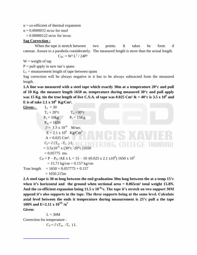
1.A line was measured with a steel tape which exactly 30m at a temperature 20°c and pull
of 10 Kg. the measure length 1650 m. temperature during measured 30°c and pull apply
was 15 Kg. tin the true length of live C.S.A. of tape was 0.025 Cm² & = 40°c is 3.5 x 10⁶ and
E is of take 2.1 x 10⁶
Kg/Cm².
Given:- Lt = 30
To = 20°c Tn =30°c
Po = 10kg Pr = 15Kg
Pm = 1650
∂ = 3.5 x 10⁻⁶
M/sec.
E = 2.1 x 10⁶ Kg/Cm
2
A = 0.025 Cm².
Ct= ∂ (Tm -To ) L
= 3.5x10-6
x (30°c -20°c )1650
= 0.05775 ms.
CP = P – PO /AE x L = 15 – 10 /(0.025 x 2.1 x106) 1650 x 10
2
= 15.71 kg/cm = 0.157 kg/cm
True length = 1650 + 0.057775 + 0.157
= 1650.215m
2.A steel tape is 30 m long between the end graduation 30m long between the at a temp 15°c
when it‟s horizontal and the ground when sectional area = 0.065cm² total weight 15.8N.
And the co-efficient expansion being 11.5 x 10⁻⁶
°c. The tape it‟s stretch on two support 30M
append it‟s also supports in the tape. The three supports being at the same level. Calculate
axial level between the ends it temperature during measurement is 25°c pull a the tape
100N and E=2.11 x 10⁵N
/n2
Given:
L = 30M
Correction for temperature :
CT = ∂ (Tm -To ) L
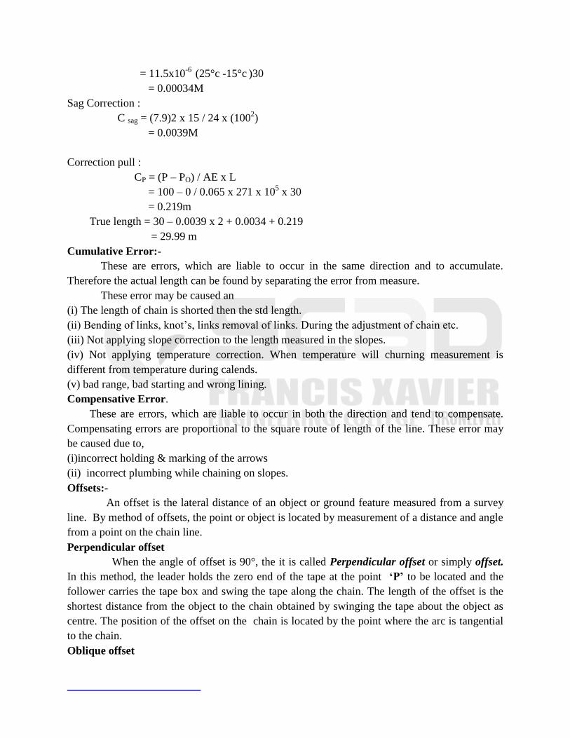
= 11.5x10⁻⁶
(25°c -15°c )30
= 0.00034M
Sag Correction :
C sag = (7.9)2 x 15 / 24 x (1002)
= 0.0039M
Correction pull :
CP = (P – PO) / AE x L
= 100 – 0 / 0.065 x 271 x 105 x 30
= 0.219m
True length = 30 – 0.0039 x 2 + 0.0034 + 0.219
= 29.99 m
Cumulative Error:-
These are errors, which are liable to occur in the same direction and to accumulate.
Therefore the actual length can be found by separating the error from measure.
These error may be caused an
(i) The length of chain is shorted then the std length.
(ii) Bending of links, knot‘s, links removal of links. During the adjustment of chain etc.
(iii) Not applying slope correction to the length measured in the slopes.
(iv) Not applying temperature correction. When temperature will churning measurement is
different from temperature during calends.
(v) bad range, bad starting and wrong lining.
Compensative Error.
These are errors, which are liable to occur in both the direction and tend to compensate.
Compensating errors are proportional to the square route of length of the line. These error may
be caused due to,
(i)incorrect holding & marking of the arrows
(ii) incorrect plumbing while chaining on slopes.
Offsets:-
An offset is the lateral distance of an object or ground feature measured from a survey
line. By method of offsets, the point or object is located by measurement of a distance and angle
from a point on the chain line.
Perpendicular offset
When the angle of offset is 90°, the it is called Perpendicular offset or simply offset.
In this method, the leader holds the zero end of the tape at the point „P‟ to be located and the
follower carries the tape box and swing the tape along the chain. The length of the offset is the
shortest distance from the object to the chain obtained by swinging the tape about the object as
centre. The position of the offset on the chain is located by the point where the arc is tangential
to the chain.
Oblique offset
when the angle is other than 90° then it is called an oblique offset
Well conditioned Triangle:-
The triangles having internal angles between 30° & 130° are known as well condition
triangle.
Ill conditioned Triangles:-
The triangles having angles less than 30° and more than 130° are known ill condition
triangle.
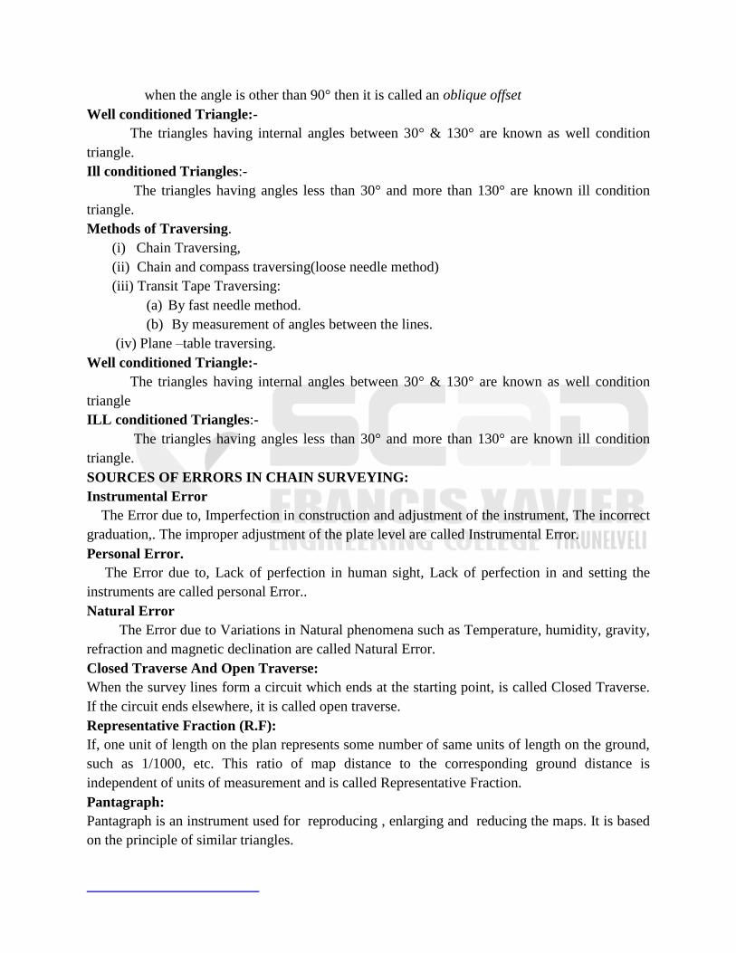
Methods of Traversing.
(i) Chain Traversing,
(ii) Chain and compass traversing(loose needle method)
(iii) Transit Tape Traversing:
(a) By fast needle method.
(b) By measurement of angles between the lines.
(iv) Plane –table traversing.
Well conditioned Triangle:-
The triangles having internal angles between 30° & 130° are known as well condition
triangle
ILL conditioned Triangles:-
The triangles having angles less than 30° and more than 130° are known ill condition
triangle.
SOURCES OF ERRORS IN CHAIN SURVEYING:
Instrumental Error
The Error due to, Imperfection in construction and adjustment of the instrument, The incorrect
graduation,. The improper adjustment of the plate level are called Instrumental Error.
Personal Error.
The Error due to, Lack of perfection in human sight, Lack of perfection in and setting the
instruments are called personal Error..
Natural Error
The Error due to Variations in Natural phenomena such as Temperature, humidity, gravity,
refraction and magnetic declination are called Natural Error.
Closed Traverse And Open Traverse:
When the survey lines form a circuit which ends at the starting point, is called Closed Traverse.
If the circuit ends elsewhere, it is called open traverse.
Representative Fraction (R.F):
If, one unit of length on the plan represents some number of same units of length on the ground,
such as 1/1000, etc. This ratio of map distance to the corresponding ground distance is
independent of units of measurement and is called Representative Fraction.
Pantagraph:
Pantagraph is an instrument used for reproducing , enlarging and reducing the maps. It is based
on the principle of similar triangles.
Methods of Traversing:
(i) Chain Traversing,
(ii) Chain and compass traversing(loose needle method)
(iii) Transit Tape Traversing:
(a) By fast needle method.
(b) By measurement of angles between the lines.
(iv) Plane –table traversing.
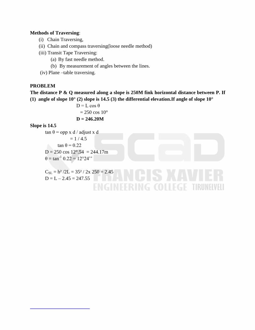
PROBLEM
The distance P & Q measured along a slope is 250M fink horizontal distance between P. If
(1) angle of slope 10° (2) slope is 14.5 (3) the differential elevation.If angle of slope 10°
D = L cos θ
= 250 cos 10°
D = 246.20M
Slope is 14.5
tan θ = opp x d / adjust x d
= 1 / 4.5
tan θ = 0.22
D = 250 cos 12°.54 = 244.17m
θ = tan-1
0.22 = 12°24‘‘
CSL = h² /2L = 35² / 2x 250 = 2.45
D = L – 2.45 = 247.55

UNIT-2
COMPASS SYRVEYING AND PLANE TABLE SURVEYING
COMPASS SURVEY
The branch of surveying in which direction of survey line are determine by a compass
and their length by a chain or tape is called compass surveying. This type of survey can be used
to measure large areas with reasonable speed and accuracy.
PRISMATIC COMPASS
Prismatic compass is a instrument used to measure the bearing of a line. It consists of a
magnetic needle pivoted at the center and is free to rotate. The area below the magnetic needle is
graduated between 0 to 360 degrees. The instrument cover consists of a sighting vane and
vertical hair to align the compass along the instrument station and the staff station.
DIP
When a magnetic needle is suspended freely it always points north. Due to certain factors
magnetic needle may not point true north, it points at a direction away from north called
magnetic north. The included angle between magnetic north and true north is called dip or
declination.
THE PRISMATIC COMPASS
1. Prismatic compass is the most convenient and portable of magnetic compass which can
either be used as a hand instrument or can be fitted on a tripod.
2. The magnetic needle is attached to the circular ring or compass card made up of
aluminium, a non- magnetic substance.
3. When the needle is on the pivot it will orient itself in the magnetic meridian and,
therefore, the N and S ends of thc ring will be in this direction.
4. The line of sight is defined by the objective vane and the eye slit, both attached to the
compass box.
5. The object vane consists of a vertical hair attached to a suitable frame while the eye slit
consists of a vertical slit cut into the upper assembly of the prism unit, both being hinged
to the box.
6. When an object is sighted, the sight vanes wilt rotate with rcspectto the NS end of ring
through an angle which the line makes with the magnetic meridian.
7. A triangular prism is fitted below the eye slit having suitable arrangement for focusing to
suit different eye sights.The prism has both horizontal and vertical faces convex, so that a
magnified image of the ring graduation is formed. When the line of sight is also in the
magnetic meridian, the South end ring comes vertically below the horizontal face of the
prism.
8. The 0°or 360° reading is, therefore, engraved on the South end of the ring, so that
bearing of the magnetic meridian is read as 0°.
9. The object vane presses against a bent lever which lifts the needle off the pivot and holds
it against the glass lid.
10. By pressing knob or break pin placed at the base of the object vane, a light spring fitted
inside the box can be brought into the contact with the edge of the graduated ring to damp
the oscillations of the needle when about to take the reading.
11. The greatest advantage of prismatic compass is that both sighting he object as well as
reading circle can be done simultaneously without hanging the position of the eye. The
circle is read at the reading at which the hair line appears to cut the graduated ring.
TEMPORARY ADJUSTMENTS
Centring : Centring is the process of keeping the instrument exactly over the station.
Levelling: If the instrument is a hand instrument, it must in hand in such a way that graduated
disc is swinging freely appears to be level as judged from the top edge of the ease.
Focusing the Prism: The prism attachment is slided up or down for focusing till the
readings are seen to be sharp and clear.
PERMANENT ADJUSTMENTS
1. 1.The permanent adjustments of prismatic compass are almost the same as that of the
surveyor‘ s except that there are no bubble tubes to be adjusted and the needle, cannot be
straightened.
2. 2.The sight vanes are generally not adjustable
THE SURVEYOR‟S COMPASS
The graduated ring is directly attached to the box and not with needle. The edge bar
needle freely floats over the pivot.Thus, the graduated card or ring is not oriented in the magnetic
meridian, as was the case in the prismatic compass.The object vane is similar to that of prismatic
compass.The eye vane consists of a simple metal vane with a fine slit.Since no prism is provided,
the object is to be sighted first with the object and eye vanes and the reading is then taken against
the North end of the needle, by looking vertically through the top glass.
When line of sight is in magnetic meridian, the North and south ends of the needle will be
over the 0° N and 0° S graduations. The card is graduated in quadrantal system having 0 at N and
S ends and 90East and West ends.Let us take the case of a line AB which is in North-East
quadrant. In order to sight the point B, the box will have to be rotated about the vertical axis. In
doing so, the pointer of the needle remains fixed in position while 0° N
graduation of the card moves in a clockwise direction. Taking when the line has a bearing of 90°
in East direction, the pointer appears to move by 90 from the 0° N graduation in anti-clockwise
direction.
BEARING.
Bearing of a line is its direction relative to a given meridian.
A meridian is any direction such as :
· True meridian
· Magnetic Meridian
· Arbitrary Meridian.
(1) True Meridian.
The meridian through a point is the line in which .a plane, passing
that point and the north and south pd intersects with surface of the earth. It, thus, passes
through the north and south.
True Bearing.
True bearing of a line is the horizontal angle which it makes with the true
meridian through one of the extremities of the line. Since the direction of true meridian
through a point remains fixed, the true bearing of a line is a constant quantity.
(2) Magnetic Meridian
Magnetic meridian through a is the direction shown by a freely
floating and balanced magnetic needle free from all other attractive forces.
Magnetic Bearing
The magnetic bearing of a line is the horizontal angle which it makes
with the magnetic meridian passing through one of the extremities of the line.
(3) Arbitrary Meridian.
Arbitrary meridian is any convenient direction towards a
permanent and prominent mark or signal, such as a church spire or top of a chimney.
Arbitrary bearing
Arbitrary bearing of a line is the horizontal angle which it makes
with any arbitrary meridian passing through one of the extremities.
CONVERSION OF W.C.B. INTO R.B.
0 & 90 R.B.=W.C.B NE
90 & 180 R.B.= 180 -W.C.B SE
180 & 270 R.B.=W.C.B.- 180 SW
270 & 360 R.B.= 360 -W.C.B. NW
CONVERSION OF R.B. INTO W.C.B.
W.C.B= R.B 0 & 90
W.C.B.= 180 - R.B 90 & 180
W.C.B.=180 +R.B. 180 & 270
W.C.B.= 360 - R.B 270 & 360
“Add the measured clockwise angles to the bearing of the previous line. If the
sum is more than 180, deduct 180°. If the sum is less than 180°, add 180°”
EXAMPLES ON ANGLES AND BEARINGS
Example :
(a)Convert the following whole circle to quadrantal bearings
(i) 22°30‘
(ii) 170º 12‘
(iii) 211°54‘
(iv) 327°24‘ .
(b) Convert the following quadrantal bearing to whole circle bearings
(i) N12°24‘E
(ii) S31°36‘ E
(iii) S 68 6‘W
(iv) N5°42‘W
Referring to fig above and tables given:
(i) R.B.= W.CB =22°30‘=N22°30‘E
(ii) R.B.= 180° —W. C. B. =180° - 170 12‘=S 9° 48‘ E
(iii) R.B.= W. C. B. — 180°=211° 54—180 °=S 31° 54‘W
(iv) R.B.= 360° —W.C.B.=360° —327° 24‘ =N 32° 36‘ W
(i)WCB= RB=12°24‘
(ii) WCB = 180° — RB = 180° — 31° 36‘ =148º 24‘
(iii)W.C.B.= 180° + R.B.= 180° + 68° 6‘ = 248º 6‘
(iv)W.C.B.= 360° — R.B. = 360° — 5°42‘ = 354°18‘
EARTH‟ S MAGNETIC FIELD AND DIP
The horizontal projections of the lines of force define the magnetic meridian. The angle
which these lines of force make with the surface of the earth is called the angle of dip or simply
the dip of the needle.
MAGNETIC DECLINATION
Magnetic declination at a place is the horizontal angle bet the true meridian and the
magnetic meridian shown by the ne at the time of observation.
If the magnetic meridian is to the right side (or eastern side) of the true meridian,
declination is said to be eastern or positive, if it to be the left side (or western side), the
declination is said to be western or negative.
WHOLE CIRCLE BEARING (WCB)
In this method bearings of lines are observed from magnetic north and are observed
directly from the prismatic compass.
QUADRENTAL BEARING (QB )
These are bearings of lines from north or south towards east or west. These values are
usually reduced from observed whole circle bearing for the ease of calculation of included angles
and plotting.
Plane Table Surveying
Definition
Plane tabling is a graphical method of survey in which the field observations and plotting
proceed simultaneously.It is means of making a manuscript map in the field while the ground can
be seen by the topographer and without intermediate steps of recording and transcribing field
notes. It can be used to tie topography by existing control and to carry its own control systems by
triangulation or traverse and by lines of levels.
Instruments used
The following instruments are used in plane table survey
a. The plane table with levelling head having arrangements for (a) levelling, (b)
rotation about vertical axis, and (c) clamping in any required position.
b. Alidade for sighting
c. Plumbing fork and plumb bob.
d. Spirit level.
e. Compass.
f. Drawing paper with a rainproof cover.
The Plane Table
Three distinct types of tables having devices for levelling the plane table and controlling
its Orientation are in common use :
Traverse Table
The traverse table consists of a small drawing board mounted on a light tripod in
such a way that the board can be rotated about the vertical axis and can be clamped in any
position. The table is levelled by adjusting tripod legs, usually by eye-estimation.
Johnson Table
This consists of a drawing board usually 45x60cm or 60x75 cm. The head consists of a
ball-and-socket joint and a vertical spindle with two thumb screws on the underside. The ball-
and-socket joint is operated by the upper thumb screw. When the upper screw is free, the table
may be tilted about the ball-and socket for levelling.
The clamp is then tightened to fix the board in a horizontal position. When the lower
screw is loosened, the table may be rotated about the vertical axis and can thus be oriented.
The Coast Survey Table
The table is superior to the above two types and is generally used for work of high
precision. The levelling of the table is done very accurately with the help of the three foot
screws. The table can be turned about the vertical axis and can be fixed in any direction very
accurately with the help of a clamp and tangent screw.
2.Alidade
A plane table alidade is a straight edge with some form of sighting device. Two types are
used : (i) Plain alidade
(ii) Telescopic alidade.
Plain Alidade.
o It is used for ordinary work.
o It generally consist of a metal or wooden rule with two vanes at the ends.
o The two vanes or sight are hinged to fold down on the rule when the alidade is not
in use.
o One of the vanes is provided with a narrow slit while the other is open and carries
a hair or thin wire. Both the slits thus provide a definite line of sight which can be
made to pass through the object to be sighted.
o The alidade can be rotated about the point representing the instrument station on
the sheet so that the line of sigh passes through the object to be sighted.
o A line is then drawn against the working edge (known as the fiducial edge) of the
alidade.
o It is essential to have the vanes perpendicular be the surface of the sheet.
o The alidade is not very much suitable on hilly area since the inclination of the line
of sight is limited.
o A string joining the tops of the two vanes is sometimes provided to use it when
sights of considerable inclination have to be taken.
Telescopic Alidade.
o The telescopic alidade is used when it is required to take in lined sights.
o Also the accuracy and range of sights are increased by its use.
o It essentially consists of a small telescope with a level tube and graduated arc
mounted on horizontal axis.
o The horizontal axis rests on a A-frame fitted with vernier fixed in position in the
same manner as that in a transit.
o All the parts are finally supported on a heavy rule, one side of which is used as the
working edge along which line may be drawn. The inclination of the line of sight
can be read on the vertical circle.
o The horizontal distance between the instrument and the point sighted can be
computed by taking stadia readings on the staff kept at the point.
o The elevation of the point can also be computed by using usual tacheometric
relations.
o Sometimes, to facilitate calculation work, a Beaman stadia are may be provided as
an extra.
o Thus, the observer can very quickly and easily obtain the true horizontal distance
from the plane table to a levelling staff placed at the point and the difference in
elevation between them.
o The same geometric principle apply to the alidade as to the transit, but the
adjustments are somewhat modified in accordance with the lower degree of
accuracy required.
3. Plumbing Fork
o The plumbing fork is used in large scale work, is meant for centring the table over
the point or station occupied by the plane table when the plotted position of that
point is already known on the sheet.
o In the beginning of the work it is meant for transferring the ground point on to the
sheet so that the plotted point and the ground station are in the same vertical line.
o The fork consists of a hair pin-shaped light metal frame having arms of equal
length, in which a plumb-bob is suspended from the end of the lower-arm.
o The fitting can be placed with the upper arm lying on the top of the table and the
lower arm below it.
o The table being centred when the plumb-bob hangs freely over the ground mark
and the pointed end of the upper arm coincides with the equivalent point on the
plan.
4. Spirit Level
o A small spirit level may be used for ascertaining if the table is properly level.
o The level may be either of the tubular variety or of the circular type, essentially
with a flat base so that it can be laid on the table and is truly level when the
bubble is central.
o The table is levelled by placing the level on the board in two positions at right
angles and getting the bubble central in both positions.
5. Compass
o The compass is used for orienting the plane table to magnetic north.
o The compass used with a plane table is a trough compass
o In which the longer sides of the trough are parallel and flat so that either side can
be used as a ruler or laid down to coincide with a straight line drawn on the paper.
6. Drawing Paper
o The drawing paper used for plane tabling must be of superior quality so that it
may have minimum effect of changes in the humidity of the atmosphere.
o The changes in the humidity of the atmosphere produce expansion and
contraction in different directions and thus alter the scale and distort the map.
o To overcome this difficulty, sometimes two sheets are mounted with their grains
at right angles and with a sheet of muslin between them.
o Single sheet must be seasoned previous of the use by exposing it alternatively to a
damp and a dry atmosphere.
o For work of high precision, fibre glass sheets or paper backed with sheet
aluminium are often used.
AJUSTMENTS OF COMPASS
Three operations are needed
Fixing : Fixing the table to the tripod.
Setting : (i)Levelling the table
(ii)Centring
(iii)Orientation.
sighting the points
Levelling
o For small-scale work, levelling is done by estimation.
o For work of accuracy, an ordinary spirit level may be used.

o The table is levelled by placing the level on the board in two positions at right
angles and getting the bubble central in both directions.
o For more precise work, a Johnson Table or Coast Survey Table may be used.
Centring
The table should be so placed over the station on the ground that the point plotted on the
sheet corresponding to the station occupied should be exactly over the station on the ground. The
operation is known as centring the plane table.
Orientation
Orientation is the process of putting the plane-table into some fixed direction so that line
representing a certain direction on the plane is parallel to that direction on the ground.
If orientation is not done, the table will not be parallel to itself at different positions
resulting in an overall distortion of the map.
The processes of centring and orientation are dependent on each other.
For orientation, the table will have to be rotated about its vertical axis, thus disturbing the
centring.
If precise work requires that the plotted point should be exactly over the ground point,
repeated orientation and shifting of the whole table are necessary.
There are two main methods of orienting the plane table
1. Orientation by means of trough compass.
2. Orientation by means of back sighting
(i) Orientation by trough compass
The plane table can be oriented by compass under the following conditions
(a) When speed is more important that accuracy.
(b) When there is no second point available for orientation.
(c) When the traverse is so long that accumulated errors in carrying the azimuth forward might
be greater than orientation by compass.
(d) For approximate orientation prior to final adjustment
(e) In certain resection problems.
(ii) Orientation by back sighting
Orientation can be done precisely by sighting the points already plotted on the sheet. Two
cases may arise
(a) When it is possible to set the plane table on the point already plotted on the sheet by way of
observation from previous station.
(b) When it is not possible to set the plane table on the point.
METHODS OF PLANE TABLING
Methods of plane tabling can be divided into four distinct
1. Radiation.
2. Intersection.
3. Traversing.
4. Resection.

The first two methods are generally employed for locating the details while the other two
methods are used for locating the plane table stations. table stations.
RADIATION
In this method, a ray is drawn from the instrument station towards the point, the distance
is measured between the instrument station and that point, and the point is located by plotting to
some scale the distance so measured. Evidently, the method is more suitable when the distances
are small and one single instrument can control the points to be detailed. The method has a wider
scope if the distances are obtained tacheometrically with the help of telescopic alidade. The
following steps are necessary to an instrument station to locate the points from an instrument
station:
1. Set the table at T, level it and transfer the point on to the sheet by means of plumbing
fork, thus getting point t representing T. Clamp the table.
2. Keep the alidade touching t and sight to A. Draw the ray along the fiducial edge of the
alidade. Similarly, sight different points B, C, D, E etc., and draw the corresponding rays.
3. Measure TA, TB, TC, TD, TE etc., in the field and plot their distances to some scale
along the corresponding rays, thus getting a, b, c, d, e etc. Join these if needed.
INTERSECTION (GRAPHIC TRIANGULATION)
Intersection is resorted to when the distance between the point and the instrument station
is either too large or cannot be measure accurately due to some field conditions. The location of
an object is determined by sighting at the object from two plane table stations and drawing the
rays. The intersection of these rays will give the position of the object. It is therefore very
essential to have at least two instrument stations to locate any point. The distance between the
two instrument stations is measured and plotted on the sheet to some scale. The line joining the
two instrument stations is known as the base line. No linear measurement other, than that of the
base line is made. The point of intersectior of the two rays forms the vertex of a triangle having
the two rays as two sides and the base line as the third line of the triangle. Due to this reason,
intersection is also sometimes known as graphic triangulation.
Procedure
The following is the procedure to locate the points by the method of intersection:
(1) Set the table at A, level it and transfer the point A on to the sheet by way of plumbing fork.
Clamp the table.
(2) With the help of the trough compass, mark the north direction on the sheet.
(3) Pivoting the alidade about a, sight it to B. Measure AB and plot it along the ray to get b. The
base line ab is thus drawn.
(4) Pivoting the alidade about a, sight the details C, D, E etc, and draw corresponding rays.
(5) Shift the table at B and set it there. Orient the table roughly by compass and finally by back
sighting A.
(6) Pivoting the alidade about b, sight the details C, D, E etc. and draw the corresponding rays
along the edge of the alidade to intersect with the previously drawn rays in c, d, e etc. The
positions of the points are thus mapped by way of intersection.
TRAVERSING
Plane table traverse involves the same principles as a transit traverse. The only difference
is that in the case of radiation the observations are taken to those points which are to be detailed
or mapped while in the case of traversing the observations are made to those points which will
sub sequently be used as instrument stations.
Procedure.
(1) Set the table at A. Use plumbing fork for transferring A on to the sheet. Draw the direction of
magnetic meridian with the help of trough compass.
(2) With the alidade pivoted about a, sight it to B and draw the ray. Measure AB and scale off ab
to some scale. Similarly draw a ray towards E, measure AE and plot e.
(3) Shift the table to B and set it. Orient the table accurately back sighting A. Clamp the table.
(4) Pivoting the alidade about b, sight to C. Measure BC and plot it on the drawn ray to the same
scale. Similarly, the table can be set at other stations and the traverse is completed.
(5) It is to be noted here that the orientation is to be done by back sighting
(6) If there are n stations in a closed traverse, the table will have to be set on at least (n — 1)
stations to know the error of closure though the traverse may be closed even by setting it on (n
— 2) stations.
RESECTION
Resection is the process of determining the plotted position of the station occupied by the
plane table, by means of sights taken towards known points, locations of which have been
plotted.
The following are the four methods of orientation:
(i) Resection after orientation by compass.
(ii) Resection after orientation by back sighting.
(iii) Resection after orientation by three-point problem.
(iv) Resection after orientation by two-point problem.
Resection after orientation by compass
The method is utilized only for small-scale or rough mapping for which the relatively
large errors due to orienting with the compass needle would not impair the usefulness of the
map.
(1) Let C be the instrument station to be located on the plan. Let A and B be two visible stations
which have been plotted on the sheet as a and b. Set the table at C and orient it with compass.
Clamp the table.
(2) Pivoting the alidade about a, draw a resector (ray) towards A; similarly, sight B from b and
draw a resector. The intersection of the two resectors will give c, the required point. of the two
resectors will give c, the required point.
Resection after orientation by backsighting
If the table can be oriented by backsighting along a previously plotted backsight line, the
station can be located by the intersection of the backsight line and the resector drawn through
another known point.
(1) Let C be the station to be located on the plan and A and B be two visible points which have
been plotted on the sheet as a and b. Set the table at A and orient it by backsighting B along ab.
(2) Pivoting the alidade at a, sight C and draw a ray. Estimate roughly the position of C on this
ray as c1
(3) Shift the table to C and centre it approximately with respect to c. Keep the alidade on the line
c1 a and orient the table by back-sight to A. Clamp the table which has been oriented.
(4) Pivoting the alidade about b, sight B and draw the resector bB to intersect the ray C1a in c.
Thus, c is the location of the instrument station.
Resection by Three-point Problem and Two-point Problem
Of the two methods described above, the first method is rarely used as the errors due to
local attraction etc., are inevitable.
In the second method, it is necessary to set the table on one of the known points and draw
the ray towards the station to be located. In the more usual case in which no such ray has been
drawn, the data must consist of either
(a) Three visible points and their plotted positions (The three- point problem).
(b) Two visible points and their plotted positions (The two point problem).
THE THREE-POINT PROBLEM
Statement: Location of the position, on the plan, of the station occupied by the plane table by
means of observations to three well-defined points whose positions have been previously plotted
on the plan
o In other words, it is required to orient the table at the station with respect to three
visible points already located on the plan.
o Let P be the instrument station and A, B, C be the points which are located as a, b,
c respectively on the plan.
o The table is said to be correctly oriented at P when the three resectors through a, b
and c meet at a point and not in a triangle.
o The intersection of the three resectors in a point gives the location of the
instrument station.
o Thus, in three-point problem, orientation and resection are accomplished in the
same operation.
The following are some of the important methods available for the solution of the
problem
(a) Mechanical Method (Tracing Paper Method)
(b) Graphical Method
(c) Lehmann‘ s Method (Trial and Error Method)
1. MECHANICAL METHOD (TRACING PAPER METHOD)
The method involves the use of a tracing paper and is, there- fore, also known as tracing paper
method.
Procedure
Let A, B, C be the known points and a, b, c be their plotted positions. L P be the position
of the instrument station to be located on the map.
(1) Set the table on P. Orient the table approximately with eye so that ab is parallel to AB.
(2) Fix a tracing paper on the sheet and mark on it p‘ as the approximate location of P with the
help of plumbing fork.
(3) Pivoting the alidade at p‘ , sight A, B, C in turn and draw the corresponding lines p‘ a‘, p‘ b‘
and p‘ c‘ on the tracing paper. These lines will not pass through a, b, and c as the orientation is
approximate.
(4) Loose the tracing paper and rotate it on the drawing paper in such a way that the lines p‘ a‘,
p‘ b‘ and p‘ c‘ pass through a, b and c respectively. Transfer p‘ on to the sheet and represent it as
p. Remove the tracing paper and join pa, pb and pc.
(5) Keep the alidade on pa. The line of sight will not pass through A as the orientation has not
yet been corrected. To correct the orientation, loose the clamp and rotate the plane table so that
the line of sight pass through A. Clamp the table. The table is thus oriented.
(6) To test the orientation, keep the alidade along pb. If the orientation is correct, the line of sight
will pass through B. Similarly, the line of sight will pass through C when the alidade is kept on
pc.
2. GRAPHICAL METHODS
There are several graphical methods available, but the method given by Bessel is more suitable
and is described first.
Bessel‟ s Graphical Solution
(1) After having set the table at station P, keep the alidade on ba and rotate the table so that A is
bisected. Clamp the table.
(2) Pivoting the alidade about b, sight to C and draw the ray xy along the edge of the alidade .
(3) Keep the alidade along ab and rotate the table till B is bisected. Clamp the table.
(4) Pivoting the alidade about a, sight to C. Draw the ray along the edge of the alidade to
intersect the ray xy in c‘ Join cc‘
(5) Keep the alidade along C‘ C and rotate the table till C is bisected. Clamp the table. The table
is correctly oriented.
(6) Pivoting the alidade about b, sight to B. Draw the ray to intersect cc‘ in p . Similarly, if
alidade is pivoted about a and A is sighted, the ray will pass through p if the work is accurate.
The points a, b, c and p form a quadrilateral and all the four points lie along the circumference of
a circle. Hence, this method is known as ― Bessel‘s Method of Inscribed Quadrilateral‖.
LEHMANN‟S METHOD
Procedure:
(1) Set the table at P and orient the table approximately so that ab is parallel to AB. Clamp the
table.
(2) Keep the alidade pivoted about a and sight A. Draw the ray. Similarly, draw rays from b and
c towards B and C respectively. If the orientation is correct, the three rays will meet at one point.
If not, they will meet in three points forming one small triangle of error.

(3) The triangle of error so formed will give the idea for the further orientation. The orientation
will be correct only when the triangle of error is reduced to one point. To do this, choose the
point p‘ as shown. The approximate choice of the position may be done with the help of
Lehmann‘ s Rules described later.
(4) Keep the alidade along p‘ a and rotate the table to sight A. Clamp the table. This will give
next approximate orientation (but more accurate than the previous one).
(5) Keep the alidade at b to sight B and draw the ray. Similarly, keep the alidade at c and sight C.
Draw the ray. These rays will again meet in one triangle, the size of which will be smaller than
the previous triangle of error, if p‘ has been chosen judiciously keeping in the view the
Lehmann‘ s Rules.
(6) Thus, by successive trial and error, the triangle of error can be reduced to a point. The final
and correct position of the table will be such that the rays Aa, Bb and Cc meet in one single
point, giving the point p. The whole problem, thus, involves a fair knowledge of Lehmann‘ s
Rules for the approximate fixation of p‘ so that the triangle of error may be reduced to a
minimum. The lines joining A, B, C (or a, b, c) form a triangle known as the Great Triangle.
Similarly, the circle passing through A, B, C or (a, b, c) is known as the Great Circle.
TWO-POINT PROBLEM
Statement: Location of the position on the plan, of the station occupied by the plane table by
means of observation to two well defined points whose position have been previously plotted on
the plan.‖ Let us take two points A and B, the plotted positions of which are known. Let C be the
point to be plotted. The whole problem is to orient the table at C.
Procedure
(1) Choose an auxiliary point D near C, to assist the orientation at C. Set the table at D in such a
way that ab is approximately parallel to AR (either by compass or by eye judgment). Clamp the
table.
(2) Keep the alidade at a and sight A. Draw the resector. Similarly, draw a resector from b and B
to intersect the previous one in c The position of d is thus got, the degree of accuracy of which
depends upon the approximation that has been made in keeping at‘ parallel to AR. Transfer the
point d to the ground and drive a peg.
(3)Keep the alidade at d and sight C. Draw the ray. Mark a point c on the ray by estimation to
represent the distance DC.
(4) Shift the table to C, orient it (tentatively) by taking backsight to D and centre it with
reference to c The orientation is, thus, the same as it was at D.
(5)Keep the alidade pivoted at a and sight it to A. Draw the ray to intersect with the previously
drawn ray from D in c. Thus, c is the point representing the station C, with reference to the
approximate orientation made at D.
(6)Pivoting the alidade about c, sight B. Draw the ray to intersect with the ray drawn from D to B
in b‘ . Thus b‘ is the approximate representation of B with respect to the orientation made at D.
(7)The angle between ab and ab‘ is the error in orientation and must be corrected for. In order
that ab and ab‘ may coincide (or may become parallel) keep a pole P in line wih ab‘ and at a

great distance. Keeping the alidade along ab, rotate the table till P is bisected. Clamp the table.
The table is thus correctly oriented.
(8) After having oriented the table as above, draw a resector from a to A and another from b to B,
the intersection of which will give the position C occupied by the table.
ERRORS IN PLANE TABLING
The degree of precision to be attained in plane tabling depends upon the character of the survey,
the quality of the instrument, the system adopted and upon the degree to which accuracy is
deliberately sacrificed for speed. The various sources of errors may be classified as
1. Instrumental Errors : Errors due to bad quality of the in strument. This includes all errors
described for theodolite, if telescopic alidade is used.
2. Errors of plotting.
3. Error due to manipulation and sighting. These include
(a) Non-horizontality of board.
(b) Defective sighting.
(c) Defective orientation.
(d) Movement of board between sights.
(e) Defective or inaccurate centring.
(a) Non-horizontality of board
The effect of non-horizontality of board is more severe when the difference in elevation between
the points sighted is more.
(b) Defective sighting
The accuracy of plane table mapping depends largely upon the precision with which points are
sighted. The plain alidade with open sight is much inferior to the telescopic alidade in the
definition of the line of sight.
(c) Defective orientation
Orientation done with compass is unreliable, as there is every possibility of local
attraction. Erroneous orientation contribute to wards distortion of the survey. This orientation
should be checked at as many stations as possible by sighting distant prominent objects already
plotted.
(d) Movement of board between sights
Due to carelessness of the observer, the table may be disturbed between any two sights
resulting in the disturbance of orientation. To reduce the possibility of such movement, the clamp
should be firmly applied. It is always advisable to check the orientation at the end of the
observation from a station.
(e) Inaccurate centring
It is very essential to have a proper conception of the extent of error introduced by
inaccurate centring, as it avoids unnecessary waste of time in setting up the table by
repeated trials.
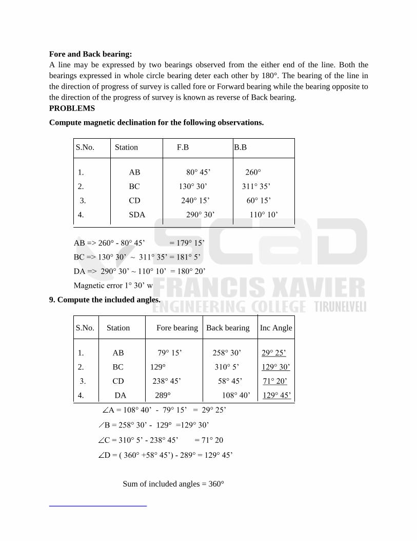
Fore and Back bearing:
A line may be expressed by two bearings observed from the either end of the line. Both the
bearings expressed in whole circle bearing deter each other by 180°. The bearing of the line in
the direction of progress of survey is called fore or Forward bearing while the bearing opposite to
the direction of the progress of survey is known as reverse of Back bearing.
PROBLEMS
Compute magnetic declination for the following observations.
S.No. Station F.B B.B
1. AB 80° 45‘ 260°
2. BC 130° 30‘ 311° 35‘
3. CD 240° 15‘ 60° 15‘
4. SDA 290° 30‘ 110° 10‘
AB => 260° - 80° 45‘ = 179° 15‘
BC => 130° 30‘ ~ 311° 35‘ = 181° 5‘
DA => 290° 30‘ ~ 110° 10‘ = 180° 20‘
Magnetic error 1° 30‘ w
9. Compute the included angles.
S.No. Station Fore bearing Back bearing Inc Angle
1. AB 79° 15‘ 258° 30‘ 29° 25‘
2. BC 129° 310° 5‘ 129° 30‘
3. CD 238° 45‘ 58° 45‘ 71° 20‘
4. DA 289° 108° 40‘ 129° 45‘
A = 108° 40‘ - 79° 15‘ = 29° 25‘
B = 258° 30‘ - 129° =129° 30‘
C = 310° 5‘ - 238° 45‘ = 71° 20
D = ( 360° +58° 45‘) - 289° = 129° 45‘
Sum of included angles = 360°

UNIT – III LEVELLING
LEVELLING
The principle of level lies in furnishing a horizontal line of sight and find the vertical
distance of the points above or below the line of site. A line of sight is provided with a level, and
a graduated leveling staff provides the vertical height of a station with reference to the level line.
TEMPORARY ADJUSTMENTS OF A LEVEL
Temporary adjustments are done before the beginning of the survey and after each
shifting of the instrument.
(i) Centering of bubble to align the line of sight horizontal using foot screws. This should
be checked often since slight disturbance of the instrument affects the line of sight to a large
extent.
(ii) Focusing of telescope to a distant object
(iii) Adjustment of eye piece to have a clear view of the cross hairs
reciprocal leveling
A method of differential leveling is based on the fact the instrument kept equidistant from
the back and forward station, The difference in elevation of two stations is equal to the difference
of the staff readings.By setting the level midway the error due to the curvature and refraction and
also the collimation error is eliminated.
sources of errors in leveling
Errors in leveling may be categorized into
(i) Personal error
(ii) Errors due to natural factors and
(iii) Instrumental error
PRINCIPLE OF LEVELLING:-
The principle of level lies in furnishing a horizontal line of sight and find the vertical
distance of the points above or below the line of site. A line of sight is provided with a level, and
a graduated leveling staff provides the vertical height of a station with reference to the level line.
SPECIAL TERM AND THEIR ABBREVIATIONS USED IN LEVELING
INSTRUMENT STATION:-
A point where instrument is set up for observations is called instrument station.

HEIGHT OF INSTRUMENT (Hi)
The elevation of line of site with respect to assumed datum is known as height of
instrument. It does not mean the height of telescope above the ground level were the level is
setup.
BACK SIGHT (B.S)
A first site taken on a level staff held at position of known elevation is called back site. It
ascertains the amount by which the line of sight is above or below the elevation of the point.
Back site enable the surveyor to obtain the height of instrument.
FORE SIGHT (F.S)
The site on a level staff held at a point of unknown elevation to ascertain by what extent
the point is above or below the line of site is called fore site. Fore site enables surveyor to obtain
the elevation of the point.
CHANGE POINT OR TURNING POINT (C.P OR T.P):
The point at which both a fore sight and back sight are taken during the operation of
levelling is called a change point. Sights are taken from two different instrument station a fore
sight ascertains the elevation of point to establish the height of instrument at the new instrument
station. The change point is always selected on a relatively permanent point.
INTERMEDIATE SIGHT:-
The F.S taken on a level staff held at points between two turning points
to determine the elevation of points is known as intermediate sight. It may be noted that for one
setting of the level there will be only a back sight and fore sight but there can be a number of
intermediate sights.
ADJUSTMENT OF LEVEL:-
A leveling instrument needs two types of adjustment.
(1) Temporary adjustment
(2) Permanent adjustment
Temporary adjustments are done before the beginning of the survey and after each
shifting of the instrument.
(i) Centering of bubble to align the line of sight horizontal using foot screws. This should
be checked often since slight disturbance of the instrument affects the line of sight to a large
extent.
(ii) Focusing of telescope to a distant object
(iii) Adjustment of eye piece to have a clear view of the cross hairs
Permanent adjustments include orientation of bubble tube axis parallel to line of sight of
the telescope, this ensures that if the bubble tube is centered the line of sight is perfectly
horizontal.
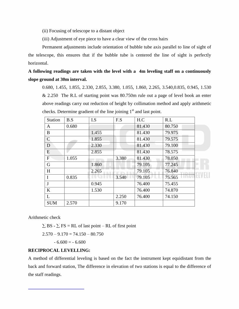
A following readings are taken with the level with a 4m leveling staff on a continuously
slope ground at 30m interval.
0.680, 1.455, 1.855, 2.330, 2.855, 3.380, 1.055, 1.860, 2.265, 3.540,0.835, 0.945, 1.530
& 2.250 The R.L of starting point was 80.750m rule out a page of level book an enter
above readings carry out reduction of height by collimation method and apply arithmetic
checks. Determine gradient of the line joining 1st and last point.
Station B.S I.S F.S H.C R.L
A 0.680 81.430 80.750
B 1.455 81.430 79.975
C 1.855 81.430 79.575
D 2.330 81.430 79.100
E 2.855 81.430 78.575
F 1.055 3.380 81.430 78.050
G 1.860 79.105 77.245
H 2.265 79.105 76.840
I 0.835 3.540 79.105 75.565
J 0.945 76.400 75.455
K 1.530 76.400 74.870
L 2.250 76.400 74.150
SUM 2.570 9.170
Arithmetic check
BS - FS = RL of last point – RL of first point
2.570 – 9.170 = 74.150 – 80.750
- 6.600 = - 6.600
RECIPROCAL LEVELLING:
A method of differential leveling is based on the fact the instrument kept equidistant from the
back and forward station, The difference in elevation of two stations is equal to the difference of
the staff readings.

By setting the level midway the error due to the curvature and refraction and also the
collimation error is eliminated. When it is not possible to set up the level midway between two
points as in the case of leveling across large water bodies the reciprocal leveling is employed to
carry forward a levels on the other side of the obstruction.
PROCEDURE:
(b1 – a1) + (b2 – a2)
h = ----------------------------- m
2
H = Differents in elevation.
Let A & B be two points on opposite banks of the lake the differents of level of A & B
may be determine as follows:
(i) Set up the level very near to A Keeping the bubble of the level tube centre ,take
reading on the staff held at A & B.
(ii) Let the staff readings are A & B be a1 and b1.Readings as A is usually taken
through the objective as a field of view is very small. A pencil may be pointed on
the staff till it is see through the telescope a connect reading is noted.
(iii) Transfer instrument to B and set it very near to B when the bubble is centered
observe the readings at A & B as a2 and b2.
A true difference in elevation between A & B is equal to the mean of the two apparent difference
of levels.
Difference in elevation between A and B is
(b1 – a1) + (b2 + a2)
h = -----------------------------
2
CURVATURE CORRECTION:-
A line of sight is the straight line Assumed to be free from effect of curvature a level live
is a curve line having its concave surface towards the earth. Due to curvature of the earth
reading taken on a leveling staff held vertically is always more than what these would have been
if the earth has a plan surface.
CC = 0.0785d²
REFRACTION CORRECTION
As line sight passes through the atmosphere it passes through regions of different
density. This causes the line of sight to bend instead of traveling straight. In order to minimize
the error due to the curvature of line of sight a correction is applied. The corrector of refraction
is always add to the staff reading.
PLOTTING OF CROSS SECTION:-
A Horizontal line is draw and different cross section are plotted on a convenient Scale
keeping the central peg of the profile in the centre. A convenient scale is assumed and the
difference of elevation of each point and the datum are plotted along the perpendicular. The
points so obtained are joining to get the desired sectional elevation. In the sectioning profile a
Horizontal & vertical scales are generally kept the same. It may be noted that the elevation of
cross datum lines for different section may be different to have the ordinates fairly short.
ERRORS IN LEVELLING :-
Errors in leveling may be categorized into
1.Personal error
2.Errors due to natural factors
3.Instrumental error
PERSONAL ERROR:-
Personal error include the following
(i) Error in sighting:
This is caused when it is difficult to see the exact coincide of the crosshairs and the staff
graduation. This may be either due to long sights or due to poor focusing of the crosshair. Some
times atmospheric air, atmospheric condition also cause on error in sighting. This error is
accidental and may be classified as compensative.
(ii) Error in manipulation:-
This is due to careless setting up of the level neither the telescope nor the tripod should be
disturbed while taking readings. The instrument should be set up on a firm ground and carefully
leveled.Take care that the bubble is centre when the readings are observed. If the bubble is not
centered a Horizontal axis telescope gets inclined affecting the staff readings. The error is more
for long sights & less for short sights. To avoid the error the observer should develop the habit
of checking the bubble before and after taking reading.

(iii) Non Vertically of staff :
If the staff is not held vertical during observation of the staff reading the observed
value will be higher than the actual value. The staff should be held vertical using a plumb bob.
Error is reading the staff :
These error generally committed are
(i) reading the staff up side down.
(ii) Reading top or bottom hair instead of center hair.
(iii) concentrating the attention on decimal part of reading and entering the whole value
wrongly.
(iv) reading the inverted staff as a vertically held staff.
Error is recording & computation :-
Common errors is recording are
(i) Entering the reading in the wrong column that is B.S reading in the I.S or F.S column.
(ii) recording the reading with digits inter change.
(iii) Omitting on entry.
(iv) Adding the F.S reading instead of subtracting with and subtracting a B.S reading instead of
adding.
Errors due to natural causes :-
(i) Errors due to curvature :-
The curvature of the earth surface lowers the elevation of the station and it is
directly proportional to the square of the horizontal distance between the staff position and the
point of observation. The correction of the curvature has to be subtracted from the observe staff
reading to get correct reading. In case of ordinary leveling error due to curvature in negligible
that is only 0.003m for a sight of 300 m length.
(ii) Error due to refraction :-
The effect of refraction on the observe readings is opposite to that of the
curvature. Refraction rise the elevation of the station on the error is also professional to the
square of the horizontal distance of the station from the level. This is negligible for short sites
and it‘s generally ignored in ordinary leveling.
(iii) Error due to wind & sun :-
Due to strong winds it is always difficult to hold the staff vertical due to non
verticality of the staff the observed reading are higher.The wind is also responsible for small
disturbance in the instrument level. In strong winds it‘s always advisable to suspend the work.
The sun causes a considerable trouble. It‘s recommended to protect the objective
by an umbrella. The effect of sun in also causes elongation of the staff due to increased
temperature but in ordinary leveling the changing in length is negligible.
Instrumental error :-
(i) Imperfect adjustment of level:- In a perfected adjusted level a line of collimation
remains horizontal when the bubble of the level tube occupies the central position. When
adjustment is not perfect the line of collimation is either inclined upwards or downwards and
observed reading are either more a less. Such errors gets compensative. If the B.S & F.S distance
are kept equal as in the case of the leveling. But in the case of inter mediate site the distance
reading are thrown into error by a different amount. Incase of leveling an steep slopes.
(ii) Defecting level tube :- If the bubble of level tube is sluggish. It will remain centre
even if the bubble axis is not horizontal or on the other hand if its two sensitive a reasonable time
is spent to bring a bubble centre. Irregularly of curvature of the tube is also a series defect.
The effect of deflective level tube also gets neutralized if the sights are of equal length.
SENSITIVITY OF LEVEL TUBE :-
The ability of level tube to express small deviation from the horizontal axis is termed as
sensitivity of level tube. Sensitiveness of a level tube is either expressed in terms of minimum
angle required by the bubble to move the smallest division on the angled scale. The sensitivity
of the level tube depends on
(i) The radius of curvature of the internal surface that is higher the radius greater the
sensitivity of the tube.
(ii) The diameter of the level tube that is larger the diameter greater is the sensitivity of
the level tube.
(iii) The length of the vapor bubble that is greater the length of the bubble more is the
sensitivity of the tube.
(iv) The viscosity and the surface tension of the bubble also affects sensitiveness of the
level tube.
(v) Smoothness of the internal surface of
UNIT-IV
LEVELLING AND APPLICATIONS
LEVELLING
Levelling is a branch of surveying the object of which is :
(1) To find the elevations of given points with respect to a given or
assumed datum,
(2) To establish points at a given elevation or at different elevations
With respect to a given or assumed datum.
Level Line A level line is a line lying in a level surface. It is, therefore, normal to the plumb line
at all points.
Horizontal Line It is straight line tangential to the level line at a point. It is also perpendicular to
the line defined by a plumb line.
BOOKING AND REDUCING LEVELS
methods of booking and reducing the elevation of points from
the observed staff readings
(1) Collimation or Height of Instrument method
(2) Rise and Fall method.
HEIGHT OF INSTRUMENT METHOD
In this method, the height of the instrument (Hi) is calculated for each setting of the
instrument by adding back sight (plus sight) to the elevation of the B.M (First point).
The elevation of reduced level of the turning point is then calculated by subtracting from
Hi the fore sight (minus sight).
For the next setting of the instrument, the H is obtained by adding the B.S taken on T.F. I
to its R.L.
The process continues till the R.L. of the last point ( a fore sight) is obtained by
subtracting the staff reading from height of the last setting of the instrument.
If there are some intermediate points, the R.L. of those points is calculated by subtracting
the intermediate sight (minus sight) from the height of the instrument for that setting.
Example:
Arithmetic check:
The difference between the sum of back sights and the sum of fore sights should be equal to the
difference between the last and the first R.L.
RISE AND FALL METHOD
In rise and fall method, the height of instrument is not at all calculated but the difference
of level between consecutive points is found by comparing the staff readings on the two points
for the same setting of the instrument.
The difference between their stall readings indicates a rise or fall according as the staff
reading at the point is smaller or greater than that at the preceding point.
The figures for ‗ rise‘ and ‗ fall‘ worked out thus for all the points give the vertical
distance of each point above or below the preceding one, and if the level of any one point is
known the level of the next will be obtained by adding its rise or subtracting its fall, as the case
may be.
Example:
Arithmetic Check:

The difference between the sum of back sights and sum of fore sights should be equal to the
difference between the sum of rise and the sum of fall and should also be equal to the difference
between the R.L. of last and first point.
LONGITUDINAL SECTIONING
PROCEDURE
Profile levelling, like differential levelling, requires the establishment of turning points
on which both back and foresights are taken.
In addition, any number of intermediate sights may be obtained on points along the line
from each set up of the instrument
It is generally best to set up the level to one side of the profile line to avoid too short
sights on the points near the instrument.
For each set up, intermediate sights should be taken after the foresight on the next turning
station has been taken.
The level is then set up in an advanced position and a back is taken on that turning point.
The position of the intermediate points on the profile are simultaneously located by
chaining a along the profile and noting their distances from the point of commencement.
when the vertical profile of the ground is regular or gradually curving, levels are taken on
points at equal-distances apart and generally at intervals of a chain length.
CROSS SECTIONING
Cross sections are run at right angles to the longitudinal profile and o either side of it for
the purpose of lateral outline of the ground Surface.
They provide the data for estimating quantities of earth work and for other purposes.
The cross-sections are numbered consecutively from the commencement of the centre
line and are set out at right angles to the main line of section with the chain and tape, the cross-
staff or the optical square and the distances are measured left and right from the centre peg
Cross-section be taken at each chain.
The length of cross-section depends the nature of work.
Plotting the profile
Contouring
A contour is an imaginary line on the ground joining the points of equal elevation.
It is a line in which the surface of ground is intersected by a level surface.
Characteristics of contours
Two contour lines of different elevations cannot cross each other. Contour lines of different
elevation intersect only in case of overhanging cliff or a cave.
Contour lines of different elevations can unite to form one line only in the case of a
vertical cliff.
Contour lines close together indicate steep slope. They indicate a gentle slope if they are
far apart.
A contour passing through any point is perpendicular to the line of steepest slope at that point.
A closed contour line with one or more higher ones inside
It. represents a hill, similarly, a closed contour line With one or more lower ones inside it
indicates a depression without an outlet To contour lines having the same elevation cannot unite
and continue as one line. Similarly, a single contour cannot split into two lines. This is evident
because the single line would, otherwise, indicate a knife-edge ridge or depression which does
not occur in nature. However, two different contours of
the same elevation may approach very near to each other.
A contour line must close upon itself, though not necessarily within the limits of the map.
Contour lines cross a watershed or ridge line at right angles. They form curves of V-
shape round it with the concave side of the curve towards the higher ground
Contour lines cross a valley line at right angles. They form sharp curves of V-shape
across it with convex side of the curve towards the higher ground If there is a stream, the contour
on either side, turning upstream, may disappear in
coincidence with the edge of the stream and cross underneath the water surface.
The same contour appears on either sides of a ridge or valley, for the highest horizontal
plane that intersects the ridge must cut it on both sides. The same is true of the lower horizontal
plane that cuts a valley.
METHODS OF CONTOURING
1.Direct method
2.Indirect method
Direct method:
The field work is of two-fold
Vertical control
Horizontal control
Vertical control
The points on the contours are traced either with the help of a level and staff or with a
help of a hand level.
The staff is kept on the B.M. and the height of the instrument is determined.
Calculate the staff reading For example if height of the instrument is 101.8m means the staff
reading will be 1.80m
Taking one contour at a time the staff man is directed to keep the staff on the point on
contour so that readings of 1.80m are obtained every time.
Horizontal control
After having located the points on various contours, they are to be surveyed with a survey
control system.
For small area chain survey may be used and points may be located by offsets.
In a work of a larger nature a traverse may be used.
INDIRECT METHOD
The following are some of the indirect methods:
i.By square
ii.By cross-section
iii.By tacheometric method
By square
The method is used when the area to be surveyed is small and the ground is not very much
undulating.
The area is divided into a number of squares.
The size of the square may vary from 5 to 20 m depending upon the nature of the contour and
contour interval.
The elevations of the corners of the square are then determined by means of a level and a
staff.
The contour lines may then be drawn by interpolation. It is not necessary that the squares
may be of, the same size.
Sometimes, rectangles are also used in place of squares. When there are appreciable
breaks in the surface between corners, guide points in addition to those at corners may also be
used.
The squares should be as long as practicable, yet small enough to conform to the
inequalities of the ground and to the accuracy required. The method is also known as spot
leveillng.
By Cross Section
In this method, cross-sections are run transverse to the centre line of a road, railway or
canal etc.
The method is most suitable for railway route surveys.
The cross-sections should be more closely spaced where the contours curve abruptly, as
in ravines or on spurs.
The cross-section and the points can then be plotted and the elevation of each point is
marked.
The contour lines are interpolated on the assumption that there is uniform slope between
two points on two adjacent contours.
Thus, the points marked with dots are the points actually surveyed in the field while the
points marked with x on the first cross-section are the points interpolated on contours.
By tacheometric method
In the case of hilly terrain the tacheometric method may be used with advantage.
A tacheometer is a theodolite fitted with stadia diaphragm so that staff readings against
all the three hairs may be taken.
The staff intercept s is then obtained by taking the difference between the readings
against the top and bottom wires.
The line of sight can make any inclination with the horizontal the range of instrument
observations.
The horizontal distances need not be measured since the tacheometer provides both
horizontal as well as vertical control.
Thus if ɵ is the inclination of the line of sight with horizontal the horizontal distance (D)
between the instrument axis and the point in which the line of sight against the central wire
intersects the staff are given by:
D=K1s cos2ɵ + K2 cos2ɵ
V= D tan ɵ
K1 & K2 are instrumental constants.
UNIT V
THEODOLITE SURVEYING
The Theodolite
The measurement of horizontal and vertical angles and it is the most precise
instrument designed for points on line, prolonging survey lines, establishing
grades, determining difference in elevation, setting out curves etc.
Theodolites may be classified as
Transit theodolite.
Non-transit theodolite.
Transit theodolite
It is the one in which the line of sight can be reversed by revolving
the telescope through 180º in the vertical plane.
Non-transit theodolite
It may be either plain theodolites or Y-theodolites in which the
telescope cannot be transited.
THE ESSENTIALS OF THE TRANSIT THEODOLITE
The Telescope
The telescope is an integral part of the theodolite and is mounted on a spindle known as
horizontal axis or trunnion axis
The telescope may be internal focusing type or external focusing type.
The Vertical Circle
The vertical circle is a circular graduated arc attached to the trunnion axis of the te1escope
consequently the graduated arc rotates with the telescope when the latter is turned about the
horizontal axis.
By means of vertical circle clamp and its corresponding slow motion or tangent screw the
telescope can be set accurately at any desired position in vertical plane.
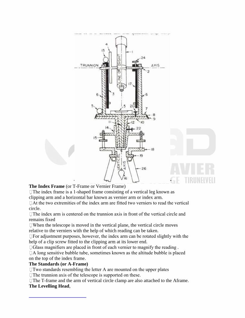
The Index Frame (or T-Frame or Vernier Frame)
The index frame is a 1-shaped frame consisting of a vertical leg known as
clipping arm and a horizontal bar known as vernier arm or index arm.
At the two extremities of the index arm are fitted two verniers to read the vertical
circle.
The index arm is centered on the trunnion axis in front of the vertical circle and
remains fixed
When the telescope is moved in the vertical plane, the vertical circle moves
relative to the verniers with the help of which reading can be taken.
For adjustment purposes, however, the index arm can be rotated slightly with the
help of a clip screw fitted to the clipping arm at its lower end.
Glass magnifiers are placed in front of each vernier to magnify the reading .
A long sensitive bubble tube, sometimes known as the altitude bubble is placed
on the top of the index frame.
The Standards (or A-Frame)
Two standards resembling the letter A are mounted on the upper plates
The trunnion axis of the telescope is supported on these.
The T-frame and the arm of vertical circle clamp are also attached to the Aframe.
The Levelling Head,

The levelling head usually consists of two parallel triangular plates known as
tribrach plates.
The upper tribrach has three arms each carrying a levelling screw
The lower tribrach plate or foot plate has a circular hole through which a
plumb bob may be suspended.
In some instruments, for levelling screws are provided between two parallel
plates.
A levelling head has three distinctive functions:
(a) To support the main part of the instrument.
(b) To attach the theodolite to the tripod.
(c) To provide a mean for levelling the theodolite.
The Two Spindles
The inner spindle or axis is solid and conical and fits into the outer spindle which
is hollow and ground conical in the interior.
The inner spindle is also called the upper axis since it carries the vernier or upper
plate
The outer spindle carries the scale or lower plate and is, therefore, also, known as
the lower axis.
Both the axes have a common axis which form the vertical axis of the instrument.
The Lower Plate (or Scale Plate)
The lower plate is attached to the outer spindle.
The lower plate carries a horizontal circle at its levellel edge and is, therefore,
also known as the scale plate.
The lower plate carries a lower clamp screw and a corresponding slow
motion or tangent screw with the help of which it can be fixed accurately in
any desired position.
When the clamp is tightened, the lower plate is fixed to the upper tribrach of
the levelling head.
On turning the tangent screw, the lower plate can be rotated slightly.
The Upper Plate (or Vernier Plate)
The upper plate or vernier plate is attached to the inner axis and carries
two verniers with magnifiers at two extremities diametrically opposite.
The upper plate supports the standards it carries an upper clamp screw
and a corresponding tangent screw for purpose of accurately fixing it to
the lower plate.
On clamping the upper and unclamping the lower clamp, the instrument
can rotate on its outer axis without any relative motion between the two
plates.
If, however, the lower clamp is clamped and upper clamp unclamped, the
upper plate and the instrument can rotate on the inner axis with a relative
motion between the vernier and the scale.
For using any tangent screw, its corresponding clamp screw must be
tightened.
The Plate Levels
The upper plate carries two plate levels placed at right angles to each
other.
One of the plate level is kept parallel to the trunnion axis.
In some theodotites only one plate level is provided.
The plate level can be centred with the help of foot screws
Tripod
When in use, the theodolite is supported on a tripod which consists of
three solid or framed legs.
At the lower ends, the legs are provided with pointed steel shoes. The
tripod head carries at its upper surface an external screw to which the foot
plate of the levelling head can be screwed.
The Plumb pob
A plumb bob is suspended from the hook fitted to the bottom of the inner axis to
centre the instrument exactly over the station mark.
The Compass
Theodolites are provided with a compass which can be either tubular type or
trough type.
A trough compass consists of a long narrow rectangular box along the
longitudinal axis of which is provided a needle balanced upon a steel pivot.
Small flat curve scales of only a few degrees are provided on each side of the
trough.
Striding Level
Some theodolites are fitted with a striding level.
It is used to test the horizontality of the transit axis or trunnion axis.
DEFINITIONS
The vertical axis
The vertical axis is the axis about which the instrument can be rotated in a horizontal
plane. This is the axis about which the lower and upper plates rotate.
The horizontal axis.
The horizontal or trunnion axis is the axis about which the telescope and the vertical
circle rotate in vertical plane.
The line of sight or line of collimation
It is the line passing through the intersection of the horizontal and vertical cross- hairs
and the optical centre of the object glass and its continuation.
The axis of level tube
The axis of the level tube or the bubble line is a straight line tangential to the longitudinal
curve of the level tube at its centre. The axis of the level-tube is horizontal when the
bubble is central.
Centring.
The process of setting the theodolite exactly over the station mark is known as centring.
Transiting.
It is the process of turning the telescope in vertical plane through 1800 about the trunnion
axis. Since the line of sight is reversed in this operation, it is also known as plunging or
reversing.
Swinging the telescope.
It is the process of turning the telescope in horizontal plane. If the telescope is
rotated in clock-wise direction, it is known as right swing., If telescope is rotated
in the anti-clockwise direction, it is know as the left swing.
Face left observation. If the face of the vertical circle is to the left of the observer, the
observation of the angle (horizontal or vertical) is known as face left observation.
Face Right Observation
If the face of the vertical circle is to the right of the observer, the observation is
known as face right observation.
Telescope normal
A telescope is said to be normal or direct when the face of the vertical circle is to
the left and the ―bubble (of the telescope) up‖.
Telescope inverted
A telescope is said to inverted or reversed when of the vertical circle is to the
right and the ―bubble down‖.
Changing face
It is an operation of bringing the face of the telescope from left to right and vice
versa.
TEMPORARY ADJUSTMENTS
Temporary adjustments or station adjustments are those which
are made at every instrument setting and preparatory to taking observation with the
instrument.
The temporary adjustments are :
(1) Setting over the station.
(2) levelling up
(3) Elimination parallax.
SETTING UP
The operation of setting up includes
Centring
Centering of the instrument over the station mark by a plumb bob or by optical
plummet, and
Approximate levelling with the help of tripod legs.
Some instruments are provided with shifting head with the help of which
accurate centring can be done easily.
By moving the leg radially, the plumb bob is shifted in the direction
of the leg while by moving the leg circumferentially or side ways considerable
change in the inclination is effected without disturbing the plumb bob.
The second movement is, therefore, effective in the approximate
levelling of the instrument.
The approximate levelling is done either with reference to a small circular bubble
provided on tribrach or is done by eye judgment.
Levelling up
After having centred and approximately levelled the instrument, accurate levelling
is done with the help of foot screws and with reference to the plate levels.
The purpose of the levelling is to make the vertical axis truly vertical.
The manner of levelling the instrument by the plate levels depends upon whether
there are three levelling screws or four levelling screws.
Three Screw Head.
Turn the upper plate until the longitudinal axis of the plate level is roughly
parallel to a line joining any two of the levelling screws

Hold these two levelling screws between the thumb and first finger of each hand
and turn them uniformly so that the thumbs move either towards each other or
away from each other until the bubble is central.
It should be noted that the bubble will move in the direction of movement of the
left thumb
Turn the upper plate through 90 degree, until the axis of the level passes over the
position of the third levelling screw C
Turn this levelling screw until the bubble is central.
Return the upper plate through 90 degree to its original position and repeat step
(2) till the bubble is central.
Turn back again through 90 degree and repeat step (4).
Repeat steps (2) and (4) till the bubble is central in both the positions.
Now rotate the instrument through 180 degree.
The bubble should remain in the centre of its run, provided it is in correct
adjustment.
Four Screw Head
Turn the upper plate until the longitudinal axis of the plate level is roughly
parallel to the line joining two diagonally opposite screws (such as D and B)
Bring the bubble central exactly in the same manner as described in step (2)
above.
Turn the upper plate through 90 degree until the spirit level axis is parallel to the
other two diagonally opposite screws (such as A and C)
Centre the bubble as before.
Repeat the above steps till the bubble is central in both the positions.
Turn through 180 degree to check the permanent adjustment, as for the three
screw instrument.
ELIMINATION OF PARALLAX
Parallax is a condition arising when the image formed by the objective is not
in the plane of the cross-hairs.
Unless parallax is eliminated, accurate sighting is impossible.
Parallax can be eliminated in two steps :
By Focusing The Eye-Piece
To focus the eye-piece for distinct vision of the cross-hairs, point the
telescope towards the sky or hold a sheet of white paper in front of the
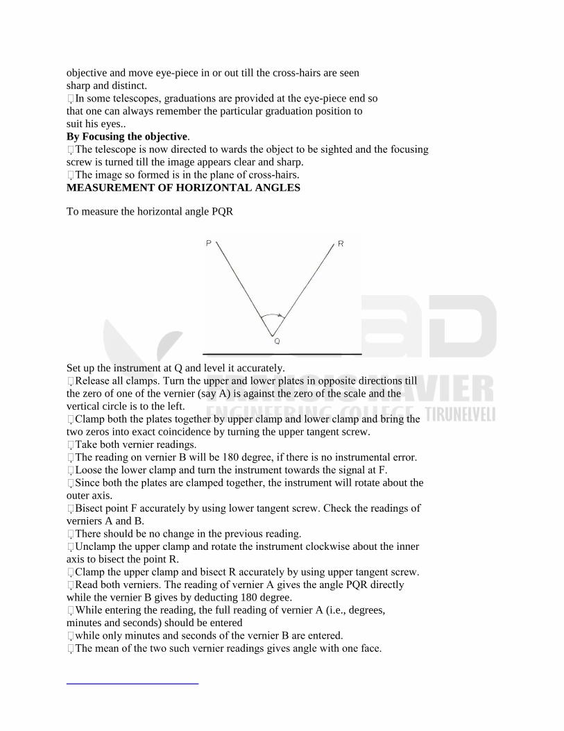
objective and move eye-piece in or out till the cross-hairs are seen
sharp and distinct.
In some telescopes, graduations are provided at the eye-piece end so
that one can always remember the particular graduation position to
suit his eyes..
By Focusing the objective.
The telescope is now directed to wards the object to be sighted and the focusing
screw is turned till the image appears clear and sharp.
The image so formed is in the plane of cross-hairs.
MEASUREMENT OF HORIZONTAL ANGLES
To measure the horizontal angle PQR
Set up the instrument at Q and level it accurately.
Release all clamps. Turn the upper and lower plates in opposite directions till
the zero of one of the vernier (say A) is against the zero of the scale and the
vertical circle is to the left.
Clamp both the plates together by upper clamp and lower clamp and bring the
two zeros into exact coincidence by turning the upper tangent screw.
Take both vernier readings.
The reading on vernier B will be 180 degree, if there is no instrumental error.
Loose the lower clamp and turn the instrument towards the signal at F.
Since both the plates are clamped together, the instrument will rotate about the
outer axis.
Bisect point F accurately by using lower tangent screw. Check the readings of
verniers A and B.
There should be no change in the previous reading.
Unclamp the upper clamp and rotate the instrument clockwise about the inner
axis to bisect the point R.
Clamp the upper clamp and bisect R accurately by using upper tangent screw.
Read both verniers. The reading of vernier A gives the angle PQR directly
while the vernier B gives by deducting 180 degree.
While entering the reading, the full reading of vernier A (i.e., degrees,
minutes and seconds) should be entered
while only minutes and seconds of the vernier B are entered.
The mean of the two such vernier readings gives angle with one face.
Change the face by transiting the telescope and repeat the whole process.
REPETITION METHOD
It is used to measure a horizontal angle to a finer degree of accuracy than that
obtainable with the least count of the vernier.
An angle is measured two or more times by allowing the vernier to remain
clamped each time at the end of each measurement instead of setting it back at
zero when sighting at the previous station.
Thus an angle reading is mechanically added several times depending upon the
number of repetitions.
The average horizontal angle is then obtained by dividing the final reading by the
number of repetitions.
To measure the angle PQR
Set the instrument at Q and level it. With the help of upper clamp and tangent
screw, set 00 reading on vernier A.
Note the reading of vernier B.
Loose the lower clamp and direct the telescope towards the point P. Clamp the
lower clamp and bisect point P accurately by lower tangent screw.
Unclamp the upper clamp and turn the instrument clockwise about the inner axis
towards R. Clamp the upper clamp and bisect R accurately with the upper tangent
screw.
Note the reading of verniers A and B to get the approximate value of the angle
PQR.
Unclamp the lower clamp and turn the telescope clockwise to sight P again.
Bisect P accurately by using the lower tangent screw.
Unclamp the upper clamp, turn the telescope clockwise and sight R. Bisect R
accurately by upper tangent screw.
Repeat the process until the angle is repeated the required number of times.
The average angle with face left will be equal to final reading divided by three.
Change face and make three more repetitions as described above.
Find the average angle with face right, by dividing the final reading by three.
The average horizontal angle is then obtained by taking the average of the two
angles obtained with face left and face right.
„Sets‟ by Method of Repetition for High Precision
First Method
Keeping the telescope normal throughout, measure the angle clockwise by 6
repetitions. Obtain the first value of the angle by dividing the final reading by 6.
Invert the telescope and measure the angle counter-clockwise by 6 repetitions -
Obtain the second value of the angle by dividing the final reading by 6.
Take the mean of the first and second values to get the average value of the angle by first set.
Take as many sets in this way as may be desired.
For first order work, five or six sets are usually required.
The final value of the angle will be obtained by taking the mean of the values obtained by
different sets.
Second Method
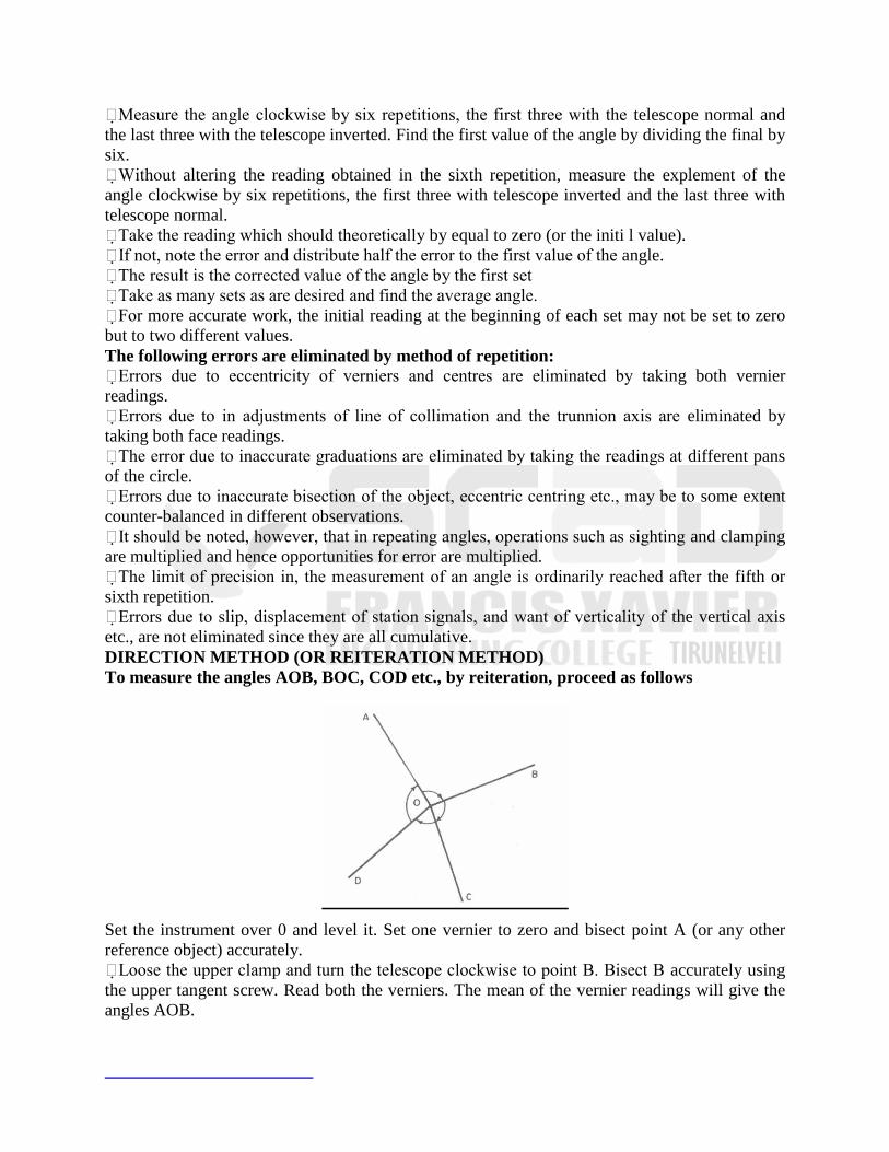
Measure the angle clockwise by six repetitions, the first three with the telescope normal and
the last three with the telescope inverted. Find the first value of the angle by dividing the final by
six.
Without altering the reading obtained in the sixth repetition, measure the explement of the
angle clockwise by six repetitions, the first three with telescope inverted and the last three with
telescope normal.
Take the reading which should theoretically by equal to zero (or the initi l value).
If not, note the error and distribute half the error to the first value of the angle.
The result is the corrected value of the angle by the first set
Take as many sets as are desired and find the average angle.
For more accurate work, the initial reading at the beginning of each set may not be set to zero
but to two different values.
The following errors are eliminated by method of repetition:
Errors due to eccentricity of verniers and centres are eliminated by taking both vernier
readings.
Errors due to in adjustments of line of collimation and the trunnion axis are eliminated by
taking both face readings.
The error due to inaccurate graduations are eliminated by taking the readings at different pans
of the circle.
Errors due to inaccurate bisection of the object, eccentric centring etc., may be to some extent
counter-balanced in different observations.
It should be noted, however, that in repeating angles, operations such as sighting and clamping
are multiplied and hence opportunities for error are multiplied.
The limit of precision in, the measurement of an angle is ordinarily reached after the fifth or
sixth repetition.
Errors due to slip, displacement of station signals, and want of verticality of the vertical axis
etc., are not eliminated since they are all cumulative.
DIRECTION METHOD (OR REITERATION METHOD)
To measure the angles AOB, BOC, COD etc., by reiteration, proceed as follows
Set the instrument over 0 and level it. Set one vernier to zero and bisect point A (or any other
reference object) accurately.
Loose the upper clamp and turn the telescope clockwise to point B. Bisect B accurately using
the upper tangent screw. Read both the verniers. The mean of the vernier readings will give the
angles AOB.
Similarly, bisect successively, C, D, etc., thus closing the circle. Read both the verniers at each
bisection. Since the graduated circle remains in a fixed position throughout the entire process,
each included angle is obtained by taking the difference between two con secutive readings.
On final sight to A, the reading of the vernier should be the same as the original setting. It not,
note the reading and find the error due to slips etc., and if the error is small, distribute it equally
to all angles. If large, repeat the procedure and take a fresh set of readings.
Repeat steps 2 to 4 with the other face.
The procedure for each set is as follows
Set zero reading on one vernier and take a back sight on A. Measure clockwise the angles
AOB, BOC, COD, DOA, etc., exactly in the same manner as explained above and close the
horizon. Do not distribute the error.
Reverse the telescope, unclamp the lower clamp and back Sigh on A. Take reading and
foresight on D, C, B and A, in counter Clockwise direction and measure angles AOD, DOC,
COB and BOA..
Two values of each of the angles are obtained.
The mean of the two is taken as the average value of each of the uncorrected angles.
The sum of all the average angles so found should be 360°.
In the case of discrepancy, the error (if small) may be distributed equally to all the angles.
The values so obtained are the corrected values for the first set.
Several such sets may be taken by setting the initial angle on the vernier to
different values.
MEASUREMENT OF VERTICAL ANGLES
Vertical angle is the angle which the inclined line of sight to an object makes with the
horizontal.
It may be an angle of elevation or angle of depression depending upon whether the object is
above or below the horizontal plane passing through the trunnion axis of the instrument.
The procedure is as follows
Level the instrument with reference to the plate level.
Keep the altitude level parallel to any two foot screws and bring the bubble central.
Rotate the telescope through 90° till the altitude bubble is on the third screw.
Bring the bubble to the centre with the third food screw.
Repeat the procedure till the bubble is central in both the positions.
Loose the vertical circle clamp and rotate the telescope in vertical plane to sight the object.
Use vertical circle tangent screw for accurate bisection.
Read both verniers (i.e. C and D) of vertical circle.
The mean of the two gives the vertical circle. Similar observation may be made with another
face. The average of the two will give the required angle.
OPERATIONS WITH THEODOLITE
TO MEASURE MAGNETICBEARING OF A LINE
To measure the magnetic bearing of a line, the theodolite should be provided with either a
tubular compass or trough compass.
Procedure
Set the instrument at P and level it accurately. Set accurately the vernier A to zero. Loose the
lower clamp.
Release the needle of the compass. Rotate the instrument about its outer axis till the magnetic
needle roughly points to north. Clamp the lower clamp.
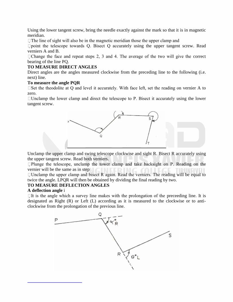
Using the lower tangent screw, bring the needle exactly against the mark so that it is in magnetic
meridian.
The line of sight will also be in the magnetic meridian those the upper clamp and
point the telescope towards Q. Bisect Q accurately using the upper tangent screw. Read
verniers A and B.
Change the face and repeat steps 2, 3 and 4. The average of the two will give the correct
bearing of the line PQ.
TO MEASURE DIRECT ANGLES
Direct angles are the angles measured clockwise from the preceding line to the following (i.e.
next) line.
To measure the angle PQR
Set the theodolite at Q and level it accurately. With face left, set the reading on vernier A to
zero.
Unclamp the lower clamp and direct the telescope to P. Bisect it accurately using the lower
tangent screw.
Unclamp the upper clamp and swing telescope clockwise and sight R. Bisect R accurately using
the upper tangent screw. Read both verniers.
Plunge the telescope, unclamp the tower clamp and take backsight on P. Reading on the
vernier will be the same as in step
Unclamp the upper clamp and bisect R again. Read the verniers. The reading will be equal to
twice the angle. LPQR will then be obtained by dividing the final reading by two.
TO MEASURE DEFLECTION ANGLES
A deflection angle i
It is the angle which a survey line makes with the prolongation of the preceeding line. It is
designated as Right (R) or Left (L) according as it is measured to the clockwise or to anti-
clockwise from the prolongation of the previous line.
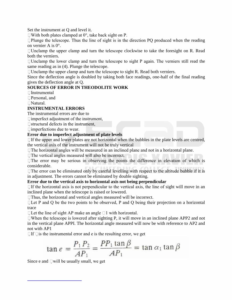
Set the instrument at Q and level it.
With both plates clamped at 0°, take back sight on P.
Plunge the telescope. Thus the line of sight is in the direction PQ produced when the reading
on vernier A is 0°.
Unclamp the upper clamp and turn the telescope clockwise to take the foresight on R. Read
both the verniers.
Unclamp the lower clamp and turn the telescope to sight P again. The verniers still read the
same reading as in (4). Plunge the telescope.
Unclamp the upper clamp and turn the telescope to sight R. Read both verniers.
Since the deflection angle is doubled by taking both face readings, one-half of the final reading
gives the deflection angle at Q.
SOURCES OF ERROR IN THEODOLITE WORK
Instrumental
Personal, and
Natural.
INSTRUMENTAL ERRORS
The instrumental errors are due to
imperfect adjustment of the instrument,
structural defects in the instrument,
imperfections due to wear.
Error due to imperfect adjustment of plate levels
If the upper and lower plates are not horizontal when the bubbles in the plate levels are centred,
the vertical axis of the instrument will not be truly vertical
The horizontal angles will be measured in an inclined plane and not in a horizontal plane.
The vertical angles measured will also be incorrect.
The error may be serious in observing the points the difference in elevation of which is
considerable.
The error can be eliminated only by careful levelling with respect to the altitude bubble if it is
in adjustment. The errors cannot be eliminated by double sighting.
Error due to the vertical axis to horizontal axis not being perpendicular
If the horizontal axis is not perpendicular to the vertical axis, the line of sight will move in an
inclined plane when the telescope is raised or lowered.
Thus, the horizontal and vertical angles measured will be incorrect.
Let P and Q be the two points to be observed, P and Q being their projection on a horizontal
trace
Let the line of sight AP make an angle 1 with horizontal.
When the telescope is lowered after sighting P, it will move in an inclined plane APP2 and not
in the vertical plane APPI. The horizontal angle measured will now be with reference to AP2 and
not with AP1
If is the instrumental error and e is the resulting error, we get
Since e and will be usually small, we get
Error due to non-parallelism of the axis of telescope level and line of
collimation
If the line of sight is not parallel to the axis of telescope level, the measured vertical angles will
be incorrect since the zero line of the vertical verniers will not be a true line of reference.
It will also be a source of error when the transit is used as a level. The
error can be eliminated by taking both face observations.
Error due to imperfact adjustment of the vertical circle vernier
If the vertical circle verniers do not read zero when the line of sight is horizontal, the vertical
angles measured will be incorrect.
The error is known as the index error and can be eliminated either by applying index correction
or by taking both face observations.
Error due to imperfect graduations
The error due to defective graduations in the measurement of an angle may be
eliminated by taking the mean of the several readings distributed over
different portions of the graduated circle.
Error due to eccentricity of verniers
The error is introduced when the zeros of the vernier are not at the ends of the
same diameter.
Thus, the difference between the two vernier readings will not be 180°, but
there will be a constant difference of other than 180.
The error can be eliminated by reading both the verniers and taking the mean of the two.
Manipulating wrong tangent screw
The error is introduced by using the upper tangent screw while taking the back sight or by
using the lower tangent screw while taking a foresight.
The error due to the former can be easily detected by checking the vernier reading after the
back sight point is sighted, but the error due to the latter cannot be detected.
It should always be remembered to use lower tangent screw while taking a back sighting and to
use upper tangent screw while taking the foresight reading.
Errors in sighting and reading
Inaccurate Bisection Of Points Observed
The observed angles will be incorrect if the station mark is not bisected accurately due to some
obstacles etc.
Care should be always be taken to intersect the lowest point of a ranging rod or an arrow
placed at the station mark if the latter is not distinctly visible.
The error varies inversely as the length of the line of sight.
If the ranging rod put at the station mark is not held vertical, the error e is given By
Parallax
Due to parallax, accurate bisection is not possible. The error can be eliminated by focusing the
eye-piece and objective.
Mistakes
Mistakes in setting the vernier, taking the reading and wrong booking of the readings.
NATURAL ERRORS
Sources of natural errors are
Unequal atmospheric refraction due to high temperature.
Unequal expansion of parts of telescope and circles due to temperature changes.
Unequal settlement of tripod. ( Wind producing vibrations)
PERMANENT ADJUSTMENTS OF THEODOLITE
The permanent adjustments of a transit are as follows
Adjustment of plate level
Adjustment of line of sight
Adjustment of the horizontal axis
Adjustment of altitude bubble and vertical index frame.
ADJUSTMENT OF PLATE LEVEL
Desired Relation
The axis of the plate bubble should be perpendicular to the vertical axis when the bubble is
central.
Object
The object of the adjustment is to make the vertical axis truly vertical ; to ensure that, once the
instrument is levelled up, the bubble will remain central for all directions of sighting
Necessity
Once the requirement is accomplished the horizontal circle and also the horizontal axis of the
telescope will be truly horizontal, provided both of these are perpendicular to the vertical axis.
Test
Set the instrument on firm ground. Level the instrument in the two positions at right angles to
each other 3 in temporary adjustment.
When the telescope is on the third foot screw, swing it through 180 degree. If the bubble
remains central, adjustment is correct.
Adjustment
If not, level the instrument with to the altitude bubble till it remains central in two position
right angles to each other.
Swing the telescope through 180 degree . If the bubble moves from its centre, bring it back
halfway with the levelling screw with the clip screw.
Repeat till the altitude bubble remains central in all positions. The vertical
axis is now truly vertical.
centralize the plate levels(s) of the horizontal plate with capstan headed screw.
ADJUSTMENT OF LINE OF SIGHT
Desired Relation
The line of sight should coincide with the optical axis of the telescope.
Object
The object of the adjustment is to place the intersection of the cross-hair in the optical axis.
Thus, both horizontal as well as vertical hair are to be adjusted.
Necessity
Horizontal hair
The adjustment is of importance only in the case of external focusing telescope in which the
direction of line of sight will change while focusing if the horizontal hair does not intersect the
vertical hair in the same point in which the optical axis docs.
Vertical hair

If the adjustment is accomplished, the line of collimation will be perpendicular to the
horizontal axis and hence the line of sight will sweep out a plane when the telescope is plunged.
Test for horizontality and verticality of hairs,
To see this, level the instrument carefully, suspend a plumb to at some distance and sight it
through the telescope by careful using.
If the image of the plumb bob string is parallel to the vertical hair, the latter is vertical.
If not, loose the capstan screws the diaphragm and rotate it till the vertical hair coincides with
the image of the string.
Adjustment of Horizontal Hair
Level the instrument carefully with all clamps fixed.
Take a reading on a staff placed some distance apart
Unclamp the lower clamp, transit the telescope and set it through 180 degree . Set the same
reading on the vertical circle and see the staff. If the same reading is obtained, the horizontal hair
is in adjustment.
Adjustment
If not, adjust the horizontal hair by top and bottom capstan screws of the diaphragm until the
reading on the staff is the mean of the two.
Repeat the test till the adjustment is corrected
Adjustment of Vertical hair
Set the instrument on a level ground) so that a length of about 100 in is available to either side
of it. Level it.
TACHOMETRY SURVEY :-
Tachometry is a branch of angular surveying in which A horizontal & vertical distance is
of points are obtain by optical means as suppose to ordinary slow process of measure by tape
chain. This methods is very rapid & convenient. All though the accuracy of tachometry is low it
is best adopted in obstructed such as steep & broken ground stretches of water etc which make
drawn age difficult. They primary object of tachometry is the preparation of contour maps are
plans required with both horizontal & vertical measurements also accuracy improvement it
provides at check an distance measure with tape.
At the instruments a normally transit theodalite pitted with stadia diaphragm is generally
used for tachometry survey. A stadia diaphragm essentially consist of one stadia hair above on
the other an equal distance below the horizontal cross hair. Telescope is used in stadia surveying
are of 3 types :-
(i) Simple external focusing telescope
(ii) External focusing analytic
(iii) Internal focusing telescope
Different system of Tachometry measurements :-
(i) Fixed hair method (or) stadia method
(ii) Movable hair method (or) substance
Fixed hair method :-
In method observation are made with stadia diaphragm having stadia wires at fixed (a)
constant distance occur. They reading an the staff corresponding to all three wires are taken. The
staff intercept that is the differents of reading corresponding to top & bottom stadia wires will
depend on the distance of the staff from the instrument when the staff intercept is more than the
length of the staff only ½ interne of real. For inclined said reading may be taken by keeping the
staff either vertical a normal to the line of site.
Subtense method :-
This method is similar to fixed hair method except the stadia internal is varying table
arrangement is may to --- distance between the stadia hair so as to said them against the two
targets on the staff kept at a point and observation this in this case the staff intercept that is the
distance between the two forgets is kept fixed while the stadia interval that is the distance
between the stadia hair is carrying as is the case of fixed hair method inclined site they out show
be taken the tangential method. They stadia being taken against the horizontal hair as against any
two point on the staff on their corresponding vertical angles are measured. This measurement of
vertical angles tube for one single observation. Staff in theodalite normal mean by perpendicular.
Least count of staff 0.005m.
Held staff vertical :-
Horizontal D = MS cos²θ + cos θ
Vertical V = MS sin²θ / 2 + C sin θ
H = height of instruct
R = observe staff reading
S = staff intercept
This is top – bottom hair radia
O = angle made by line of site with horizontal
Reduced level of θ = R.L of p + h-v-r
RL of p + h + v – r = RL of O
Staff normal to lined site :
Find the elevation & horizontal distance of point Q view from A is than angle of 30°
above horizontal with staff intercept with staff held vertically occur 3.855 m & C.H reading
1.930 m elevation of point A is 10m above m.s.l take multiplying as 100 assume h to be 1 m
RL of A = 10.000 m
RL of Q = RL of A + height of instrument + v – r
V = MS sin²θ / 2 + c sinθ
= 100 x 3.855 sin²30° / 2
= 48.19m
reduce level of Q = 10.000 + 1.000 + 48.190 – 1.930
= 57.260m
Horizontal distance :
D = MS cos²θ + cosθ
= 100 x 3.855 cos²30° / 2
reduce level Q= 57.260m
2. Find vertical & horizontal distance between point A & B. If the instrument located 0.8m above
A clip of 22° to a staff held normal to the line of site at B. The staff read 1.650, 2.150, 2.650
Assume m = 100
RL of θ = RL of A + h – v- r cosθ
S = 1m
R = 2.150 r cosθ = 1.993
V = (ms + c) sinθ
= (100 x 1) sin 22° = 37.461m
RL of θ = 0 + 0.8 – 37.461 – 1.993
= 38.654m
horizontal distance D
D = (ms + c) cosθ + r sinθ
= (100) cos 22° + 0.805
D = 93.51m
3. To determine distance between two points with base of one point is axiable and instrument
station in the same vertical plane as the elevated object.
d tan²θ
D = -------------------
tanθ1 – tan θ2
h = D tanθ1
Instrument with two different Axis :-
(d + s cot θ2 ) tanθ2
D = ---------------------------
tanθ1 – tan θ2
(d + s cot θ2 ) sinθ1 sinθ2
h = -----------------------------------
sin (θ1 – θ2 )
h2 = h1 + s
use positive sign with s cot θ2 when instrument a axis a Q is lower & negative sign when it‘s
height the instrument axis at P.
1. An instrument was setup at station P and the angle of elevated to an objective was 9°30‘ the
same object was focus from a point 4m away the first one angle was 11° 150‘ the staff reading s
from a B.M having elevation 2650.38m are 1.310m and 1.815m respectively. Find the RL of Q =
θ1 = 9°30‘ θ2 = 11°15‘
(d - s cot θ2 ) tanθ2
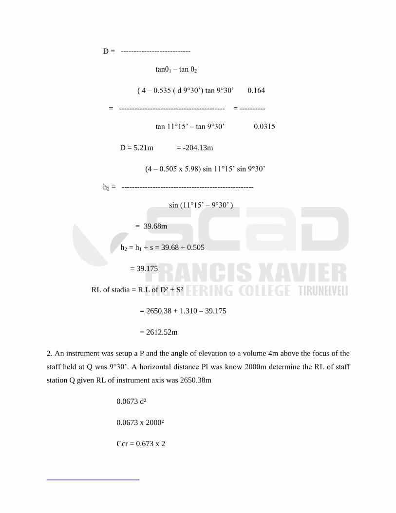
D = ---------------------------
tanθ1 – tan θ2
( 4 – 0.535 ( d 9°30‘) tan 9°30‘ 0.164
= ----------------------------------------- = ----------
tan 11°15‘ – tan 9°30‘ 0.0315
D = 5.21m = -204.13m
(4 – 0.505 x 5.98) sin 11°15‘ sin 9°30‘
h2 = ---------------------------------------------------
sin (11°15‘ – 9°30‘ )
= 39.68m
h2 = h1 + s = 39.68 + 0.505
= 39.175
RL of stadia = R.L of D² + S²
= 2650.38 + 1.310 – 39.175
= 2612.52m
2. An instrument was setup a P and the angle of elevation to a volume 4m above the focus of the
staff held at Q was 9°30‘. A horizontal distance Pl was know 2000m determine the RL of staff
station Q given RL of instrument axis was 2650.38m
0.0673 d²
0.0673 x 2000²
Ccr = 0.673 x 2

= 0.27m
V = D tanθ
= 2000 x tan 9°30‘ = 334.69m
RL of Q = RL of instrument axis + Ccr + V – h
= 2650.38 + 0.27 + 334.69 – 4
= 2981.34m
3. A instrument was setup a P and angle of depression to a plane 2m above the fast of the staff
held at Q was 5° 36‘ H. d between P & Q was 3000m determine RL of staff station Q given the
staff readings as a B.M of elevation 436.050m was 2.865m
Cn = 0.0673 x 3² = 0.6057
V = 3000 x tan 5°36‘ = 294.15m
RL of Q = BM + cn – V – n + instrument
= 436.050 + 2.865 – 0.6057 – 294.15
= 142.16m
Measurement of horizontal angles :-
(i) Direct method
(ii) Method of Repetition
(iii) Method of Reiteration
Precaution to be taken theodalite observation :-
(i) Turn the theodalite by the standards and not by using telescope ensuring slow &
smooth movement.
(ii) Done force the foot screws & tangent screws to heart.
(iii) Clamp vertical axis tightly while observing the horizontal angles.
Sources of errors in theodalite :-
(i) Instrumental Error
(ii) Personal Error
(iii) National Error