
CE-201Basics of Micro Station
27
BASICS OF MICROSTATION SUBMITTED BY: NITIN AGARWAL B.TECH. II YEAR (ECE) ENROLL. NO. - 08116027
-
Upload
arpit-jain -
Category
Documents
-
view
353 -
download
3
Transcript of CE-201Basics of Micro Station
BASICS OFMICROSTATION
SUBMITTED BY:
NITIN AGARWALB.TECH. II YEAR (ECE) ENROLL. NO. - 08116027

When we do a design in MicroStation, our design can be very large or complex. It will be very useful if we can open several views to see the design from different angle/perspective (for 3D) or simply open different views to show different areas. Imagine you have a very large area. Instead of zooming and panning every time you want to see different area, you can show them in different views.
Working With Workspace and Design Files
When we start a Windows application, most of us will create and open a new file.
But not MicroStation. MicroStation have two types of file: 2D DGN and 3D DGN.
DGN is stand for design file. Not limited to DGN, you can also create a new DWG
file. If you are not familiar with this file type, it’s AutoCAD file.
Creating Workspace
We can create multiple workspaces in MicroStation. If you need to design different drawings
for different industries, you can set each of them in a separate workspace. This will avoid
you to arrange tools and interface each time you need to create drawings in different
industry. You can also use workspace if you have multiple users working on the same
workstation.
Let’s create a new workspace that you will use for this tutorial until the end. Open your
MicroStation. If you already open it, close your file. You will see MicroStation Manager.
From user option list, select new…
MicroStation will ask you to give description for this user configuration. Type MicroStation
tutorial then click OK.

We have defined a user configuration for this tutorial. Now let’s create a new project.
From project option list, select new. Give name for this project: MicroStation Tutorial Files.
MicroStation will create a folder at this location (for Windows Vista):
C:\ProgramData\Bentley\MicroStation\WorkSpace\Projects\MicroStationTutorialFiles
If you use Windows XP, you can find it in C:\Documents and Settings\All
Users\Application Data\Bentley\…folder.
Workspace can help you to manage your files for different users, different project. But it
doesn’t mean that you have to save all files in that folder. You can still save your files to your
desktop, C:\data folder, etc.
Create New File
Let’s try to create a new file. On the upper right of MicroStation Manager, you should see
new file button. Click it.
Give the file name My First Drawing. Do not click save yet. Check the seed file. If it’s not
showing seed2D.dgn, click browse and select it. Seed file is a drawing you can start with.
Other applications call it a template file.
Click save. You will see MicroStation created a new file with that name. Select it, and click
open.
Set your Working Unit
MicroStation works differently in handling working unit compared to AutoCAD..
You have to define your working unit at the very beginning. Before you start drawing. You
can check your working unit by accessing menu settings>design file. Click on category
working units on the left.
By default, in country using metric, MicroStation will define the master unit (MU) as meters
and sub unit as millimeters. If it’s not your working units, change it now. After you finish, click
OK.
That’s how you create a new file. I’ll stop right here now, and we will discuss more about
working units.
To Understand Working Units
Have you copied the tutorial files to our tutorial project? Click open. You should see several
files if you have copied them. Find working_unit.dgn and open it. Don’t laugh at the design
:) Yes, it is a very simple drawing.
See the dimension. They show measurement in mm. Open design file settings, and change
the MU to meters. Close the dialog and see what happen.
The dimensions are showing meters now!

Now try to activate Place Smartline.
Click anywhere on your drawing area, an look at the AccuDraw. It’s showing measurement
in meters. Click several times to draw lines. Right click to finish. When MicroStation ask you
to choose right click button function, just let it be default value. Click OK.
Try to change the working unit again. Now try to place smartline again. You will see the
measurement showing different scale, even you create approximately line with same length!
Now it’s using the new working units. So don’t forget to check your drawing unit first!
Saving File and Settings
Close MicroStation. Did MicroStation ask you to save your design file? No. You placed some
lines before, when you open the file again, you will still see the lines. Even you didn’t save
the file. MicroStation automatically save it to your file, every time you create an object. It can
be a good news for you, or maybe a bad news for some of you. However, better is to save
your file regularly by accessing file>saveor press [ctrl] + S.
But now look at the dimensions. We have change the working units to meters (or you may
have changed it to something else) but it still showing millimeters! You need to save settings
separately with saving file. There are a lot of settings you can save. We will get to this later.
You san save the settings by accessing menufile>save settings or press [ctrl] + F.
Task Navigation : where your tools are.
You can change active task from tasks list. Let’s say you need to give your objects dimension. If you
want to focus to dimension tools only, you can switch the active task to drawing>dimension. You will
only see dimension tools in active task.
Main tasks are the tools you will see no matter what your active task is. Main task mostly consist tools
related to objects manipulations and modifications.

See several icons next to active task title bar? You can change the display by clicking it. Choose
which you think suit you most.
Now try to click the icon. That will activate the tool. Yeah, aren’t all Windows application works that
way? But now try to click on Place SmartLine tool, hold your mouse button. What do you see? You
will see all similar tools to create lines! You can select any other tools you want.
Try to click the ‘open linear as toolbox’ from the selection. That will open a toolbar for linear tools.

Drawing Elements: Line, Circles and Polygon
Circle and polygon are closed shapes. Closed shapes have some properties that open shapes don’t.
You will see area, fill type, and fill color. You can change the fill type to opaque or outlined. Opaque
will place the circle and fill the object with fill color you choose. Outlined will also place the circle with
fill color, but still preserve the outline color.
Tips: If you don’t see the fill color, click view attributes on your view toolbar. Select fill. It’s the first icon
on your view toolbar.
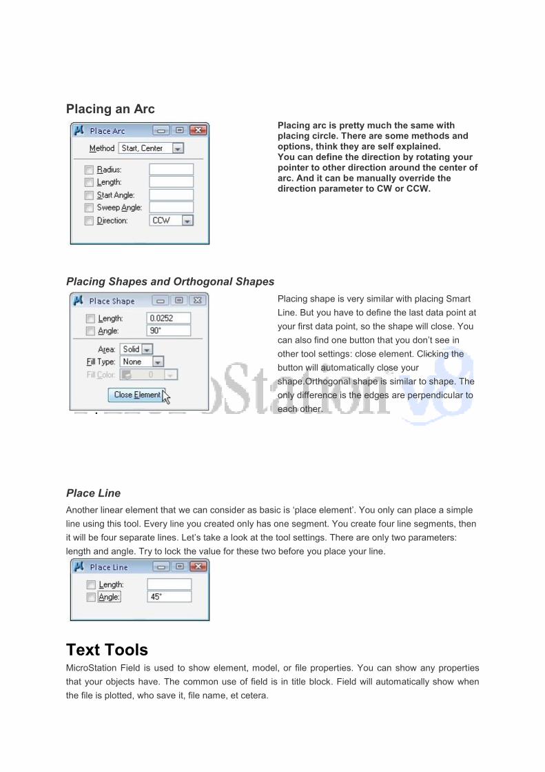
Placing an ArcPlacing arc is pretty much the same with placing circle. There are some methods and options, think they are self explained.You can define the direction by rotating your pointer to other direction around the center of arc. And it can be manually override the direction parameter to CW or CCW.
Placing Shapes and Orthogonal Shapes
Placing shape is very similar with placing Smart
Line. But you have to define the last data point at
your first data point, so the shape will close. You
can also find one button that you don’t see in
other tool settings: close element. Clicking the
button will automatically close your
shape.Orthogonal shape is similar to shape. The
only difference is the edges are perpendicular to
each other.
Place Line
Another linear element that we can consider as basic is ‘place element’. You only can place a simple
line using this tool. Every line you created only has one segment. You create four line segments, then
it will be four separate lines. Let’s take a look at the tool settings. There are only two parameters:
length and angle. Try to lock the value for these two before you place your line.
Text ToolsMicroStation Field is used to show element, model, or file properties. You can show any properties
that your objects have. The common use of field is in title block. Field will automatically show when
the file is plotted, who save it, file name, et cetera.

This is a simple drawing that showing rooms concept. We are going to show the rooms area using
fields.
Activate place text tool, type “Area =” (without quote). We can add field by right clicking in word
processor, and select insert field from context menu.
MicroStation will ask you what field type you want to insert. Select ‘element properties’.

Select any rectangle in the drawing. MicroStation will open a dialog box. All the rectangle properties
are here. Select ‘area’ field in geometry category. Make sure you see the area value at the bottom of
this dialog. Click OK.
Other Text ToolsThese are some more text tools that you might will use frequently.
Match Text AttributesWe need to change the value in tool settings regularly. When we place text, sometimes we want to
match all the values to existing text in our drawing. This is the right tool for it. Activate it, and select a
text in your drawing to match it’s attributes.
Change Text AttributesThis one is for changing existing text attributes.
Copy Increment TextYou can copy text that contain numeric numbers and create incremental copies.
Using Mouse and Controlling ViewMouse as a pointing device has become indispensable in design
applications. Each applications may have unique function on mouse
buttons. We will discuss about it here.
View control also have important role. You will do a lot of zooming

out, zooming in, panning, and other control during the design. Let’s make you comfortable
with it before we continue further.
Mouse Button Function
1. Left button (1) is called data point (DP) in MicroStation. When we place an object, we
will need to define a data point. Either a start point, center point, next point… any kind of
points! We can define it by clicking the left mouse. I guess that’s why they call it data
point. We can also use data point to activate tools from task navigation and as OK/accept
button.
2. Right button (2) is called as Reset. Since MicroStation V8 XM, we can choose not to use
it as reset button. But let’s just use it as reset button first. Reset is used to cancel a
running process or finish using a tool.
3. Tentative button is when you press both left (1) and right (2) button at the same time.
We use this for temporary snap.
4. X Button is your mouse mid button. It’s only available for 3 button mouse. But I guess no
body using CAD still using 2 button mouse anyway :)
Clicking this button will activate/deactivate pan (no need to hold it).
Clicking it twice will activate fit view. MicroStation rescale your view to show every
objects in your drawing.
Scrolling this button will zoom in/zoom out the drawing area.
When the first time you use Reset button, you may see this dialog. MicroStation will ask you
whether you want to use right click for Reset or pop up menus. Suggestion is to you is to
leave the default value: use it as reset button.

That’s the basic. We can combine the mouse button with [ctrl], [shift], and/or [alt]. You can
see all this mouse function from MicroStation menu Worskpace>Button
Assignment… Don’t try to change anything yet. Just take a look for what you can do with
them.
View ControlEach MicroStation view has a view control bar. You can zoom, rotate, and pan your views individually.
And you can get previous/next view from each of them too!

You can find view control toolbar under each view. If you are familiar with Windows applications, it
shouldn’t be hard. We will discuss most used tools first, and the others later. Not all of them available
for 2D drawings, so you might not see some of them.
We can use window area to magnify selected area in our drawing. You need to define two data
points when you use this tool.
Fit view will adjust the drawing view scale automatically until you can see all of your object.
Alternatively, you can double click your X
Pan view is used to pan or move your drawing area. Just like you move your paper aroun
another part of your drawing. Activate it, and click your data point to pan view. Alternatively, you can
press your X-button.
Arrange and Manage MicroStation ViewsAfter we open several views, we can tile or arrange them just like in other Wind
using windows menu>tile. You can cascade or arrange them too.
You can find view control toolbar under each view. If you are familiar with Windows applications, it
be hard. We will discuss most used tools first, and the others later. Not all of them available
for 2D drawings, so you might not see some of them.
to magnify selected area in our drawing. You need to define two data
Fit view will adjust the drawing view scale automatically until you can see all of your object.
Alternatively, you can double click your X-button.
Pan view is used to pan or move your drawing area. Just like you move your paper aroun
another part of your drawing. Activate it, and click your data point to pan view. Alternatively, you can
Arrange and Manage MicroStation ViewsAfter we open several views, we can tile or arrange them just like in other Wind
using windows menu>tile. You can cascade or arrange them too.
However, sometimes it’s easier to meet our
requirement just by dragging the views corner,
and drag the title bar to move the views to their
desired position.
When we work with common views arrangement,
we can save the MicroStation views arrangement
using view group.
You can find view control toolbar under each view. If you are familiar with Windows applications, it
be hard. We will discuss most used tools first, and the others later. Not all of them available
to magnify selected area in our drawing. You need to define two data
Fit view will adjust the drawing view scale automatically until you can see all of your object.
Pan view is used to pan or move your drawing area. Just like you move your paper around to see
another part of your drawing. Activate it, and click your data point to pan view. Alternatively, you can
After we open several views, we can tile or arrange them just like in other Windows applications:
However, sometimes it’s easier to meet our
requirement just by dragging the views corner,
and drag the title bar to move the views to their
When we work with common views arrangement,
we can save the MicroStation views arrangement

Element Manipulation
Copy And Move Element. We select the elements, define the first point and then define the distance and direction for the
duplicate location. If we use copy, then the original elements will remain. But move, the original
elements will be deleted.
Scale.
If we know the scale value, then
we can use active scale. if don’t
know the scale value, just the
final size, we can use 3 points.
We define the scale base point,
reference 2nd point to define
existing size, and then 3rd point
as the expected size.Be careful
with X scale and Y scale in active
scale method, or proportional in 3
points method. MicroStation can
resize elements to only one axis.
RotateWe can rotate MicroStation elements using 3 methods: by active angle, 2 points, and 3 points. Active
angle and 3 points are the same with the one we use in MicroStation scale tool. 2 points is almost
similar with 3 points, but it will use X positive axis as the 0 degree.
MirrorThis tool name is already explain what it does: mirror elements. We can mirror element vertically,
horizontally, or use a virtual line as a mirror line.

Align Elements by EdgeMicroStation Align by Edge is used to align elements to another element edge as reference.
Copy ParallelThis MicroStation tool is used to
copy an element parallel to
original element. There are 3
modes we can use: miter, round,
and original. Round will create
rounded edges. Miter will keep
the result distance the same, and
might try to add more vertex. You
can only see the effect for some
element types, such as ellipse.
Original, will keep the original
shape. It might not true parallel
with original object.
Using MicroStation Cell
When we draw, we need to draw same objects repeatedly. It can be a standard
objects/parts, annotation, symbol, etc. In
a transparent paper that contains those symbol. We place it above our paper, scratch it…
and voila! We have it on our drawing.
MicroStation cell have the similar concept. We can define and save the objects
library. And whenever we need it, we just look for it in our library and use it. No need to draw
the same object repeatedly. In this post, we will discuss how we can use existing
MicroStation cell library. On the next post, we will discuss how we
MicroStation cell library.
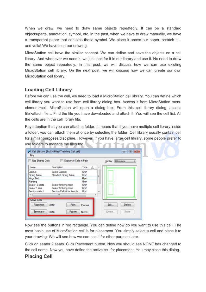
Loading Cell LibraryBefore we can use the cell, we need to load a MicroStation cell library. You can define which
cell library you want to use from cell library dialog box. Access it from MicroStation menu
element>cell. MicroStation will open a dialog box. From this cell library dialog, access
file>attach file… Find the file you have downloaded and attach it. You will see the cell list. All
the cells are in the cell library file.
Pay attention that you can attach a folder. It means that if you have multiple cell library inside
a folder, you can attach them at once by selecting the folder. Cell library usually contain cell
for similar purposes/discipline. However, if you have large cell library, some people pre
use folders to manage the files too.
Now see the buttons in red rectangle. You can define how do you want to use this cell. The
most basic use of MicroStation
your drawing. We will see how we can use it for other purpose later.
Click on seater 2 seats. Click Placement button. Now you should see NONE has changed to
the cell name. Now you have define
Placing Cell
When we draw, we need to draw same objects repeatedly. It can be a standard
objects/parts, annotation, symbol, etc. In the past, when we have to draw manually, we have
a transparent paper that contains those symbol. We place it above our paper, scratch it…
and voila! We have it on our drawing.
MicroStation cell have the similar concept. We can define and save the objects
library. And whenever we need it, we just look for it in our library and use it. No need to draw
the same object repeatedly. In this post, we will discuss how we can use existing
MicroStation cell library. On the next post, we will discuss how we can create our own
Before we can use the cell, we need to load a MicroStation cell library. You can define which
cell library you want to use from cell library dialog box. Access it from MicroStation menu
lement>cell. MicroStation will open a dialog box. From this cell library dialog, access
file>attach file… Find the file you have downloaded and attach it. You will see the cell list. All
the cells are in the cell library file.
tach a folder. It means that if you have multiple cell library inside
a folder, you can attach them at once by selecting the folder. Cell library usually contain cell
for similar purposes/discipline. However, if you have large cell library, some people pre
use folders to manage the files too.
Now see the buttons in red rectangle. You can define how do you want to use this cell. The
most basic use of MicroStation cell is for placement. You simply select a cell and place it to
your drawing. We will see how we can use it for other purpose later.
Click on seater 2 seats. Click Placement button. Now you should see NONE has changed to
the cell name. Now you have define the active cell for placement. You may close this dialog.
When we draw, we need to draw same objects repeatedly. It can be a standard
the past, when we have to draw manually, we have
a transparent paper that contains those symbol. We place it above our paper, scratch it…
MicroStation cell have the similar concept. We can define and save the objects on a cell
library. And whenever we need it, we just look for it in our library and use it. No need to draw
the same object repeatedly. In this post, we will discuss how we can use existing
can create our own
Before we can use the cell, we need to load a MicroStation cell library. You can define which
cell library you want to use from cell library dialog box. Access it from MicroStation menu
lement>cell. MicroStation will open a dialog box. From this cell library dialog, access
file>attach file… Find the file you have downloaded and attach it. You will see the cell list. All
tach a folder. It means that if you have multiple cell library inside
a folder, you can attach them at once by selecting the folder. Cell library usually contain cell
for similar purposes/discipline. However, if you have large cell library, some people prefer to
Now see the buttons in red rectangle. You can define how do you want to use this cell. The
cell is for placement. You simply select a cell and place it to
Click on seater 2 seats. Click Placement button. Now you should see NONE has changed to
the active cell for placement. You may close this dialog.

Access place active cell from task navigation. Now you can see the active MicroStation cell
on your pointer, and dynamically determine the cell location. Click your mouse at the desi
position.
You can change several settings before you place it. These are the basic settings for placing
cell.
Tips: You can double click the cell name in cell library list. This will also activate place active
cell.
Understanding Shared Cell
You can stretch MicroStation cell and change the text data field value within cell. So if you
have similar objects, but have different sizes, you can create a cell and stretch it later.
However, there are some cells that you don’t need to modify. To prevent this t
being modified, you can use shared cell. Activate
The other advantage of using shared cell is, you can reduce your MicroStation design files.
Shared cells using the same information for every instan
cell, if you have 100 cells, then you have 100 cell information! I’m not sure if this is still an
issue now, as any new computer now can handle quite a large file easily.
Creating MicroStation Cell
Cell is a common drawing element that you can use over and over again. In other word: it’s a
library. So how to create MicroStation cell
Access place active cell from task navigation. Now you can see the active MicroStation cell
on your pointer, and dynamically determine the cell location. Click your mouse at the desi
You can change several settings before you place it. These are the basic settings for placing
Tips: You can double click the cell name in cell library list. This will also activate place active
Understanding Shared Cell
stretch MicroStation cell and change the text data field value within cell. So if you
have similar objects, but have different sizes, you can create a cell and stretch it later.
However, there are some cells that you don’t need to modify. To prevent this t
being modified, you can use shared cell. Activate use shared cell in cell library dialog box.
The other advantage of using shared cell is, you can reduce your MicroStation design files.
Shared cells using the same information for every instance in your drawing. Without shared
cell, if you have 100 cells, then you have 100 cell information! I’m not sure if this is still an
issue now, as any new computer now can handle quite a large file easily.
Creating MicroStation Cell
Cell is a common drawing element that you can use over and over again. In other word: it’s a
to create MicroStation cell?
Access place active cell from task navigation. Now you can see the active MicroStation cell
on your pointer, and dynamically determine the cell location. Click your mouse at the desired
You can change several settings before you place it. These are the basic settings for placing
Tips: You can double click the cell name in cell library list. This will also activate place active
stretch MicroStation cell and change the text data field value within cell. So if you
have similar objects, but have different sizes, you can create a cell and stretch it later.
However, there are some cells that you don’t need to modify. To prevent this type of cell
in cell library dialog box.
The other advantage of using shared cell is, you can reduce your MicroStation design files.
ce in your drawing. Without shared
cell, if you have 100 cells, then you have 100 cell information! I’m not sure if this is still an
Cell is a common drawing element that you can use over and over again. In other word: it’s a

You need to draw your objects before you convert it to a cell. You can use SmartLine, block,
circle, etc. After you finish, you can convert all the objects to a single cell.
Understanding Cell LibraryBefore we can actually create our cell,we need
usually holds several similar cells. For example, you want a library of cars. You can create a
cell library file named cars. Then you might want to create a cell library to keep your
annotation symbols, or probably AEC symbols. That’s what a cell library is for. It keeps a
similar cells within one file.
Let us try to create a cell library and cells.
objects that we want to save as cells.
They are created from simple elements such as text, line, circle, arc and line string. These
are the objects that form the elevation view symbol.
From MicroStation menu, select
Take a look to the dialog title. It says
It means that we haven’t attached any cell library yet. From this dialog menu, click
Type a name for the new cell library.
Now the dialog title will show you the cell name, but this cell library is still empty. Look at the
right bottom of this dialog. you will see several buttons to create and modify cells. But all of
them are grayed and disabled.
the cell origin before we start creating it.
Creating CellNow that we have created a cell library, we can start saving our cells here. This is a little bit
tricky, especially for AutoCAD users. Move away the dialog box a bit, but don’t close it. Just
enough for you to see the objects you are going to convert as a cell. Let’s start with the
You need to draw your objects before you convert it to a cell. You can use SmartLine, block,
circle, etc. After you finish, you can convert all the objects to a single cell.
Understanding Cell Libraryate our cell,we need to create a cell library
usually holds several similar cells. For example, you want a library of cars. You can create a
cell library file named cars. Then you might want to create a cell library to keep your
ation symbols, or probably AEC symbols. That’s what a cell library is for. It keeps a
Let us try to create a cell library and cells. Download this file and open it. We have 3 simple
objects that we want to save as cells.
They are created from simple elements such as text, line, circle, arc and line string. These
are the objects that form the elevation view symbol.
From MicroStation menu, select element>cells. The cell library dialog box will be opened.
Take a look to the dialog title. It says cell library: [NONE].
It means that we haven’t attached any cell library yet. From this dialog menu, click
Type a name for the new cell library. Something like Training Cell will do. Click save.
Now the dialog title will show you the cell name, but this cell library is still empty. Look at the
right bottom of this dialog. you will see several buttons to create and modify cells. But all of
grayed and disabled.Why the create cell button is disabled? We need to define
the cell origin before we start creating it.
Now that we have created a cell library, we can start saving our cells here. This is a little bit
or AutoCAD users. Move away the dialog box a bit, but don’t close it. Just
enough for you to see the objects you are going to convert as a cell. Let’s start with the
You need to draw your objects before you convert it to a cell. You can use SmartLine, block,
to create a cell library first. A cell library
usually holds several similar cells. For example, you want a library of cars. You can create a
cell library file named cars. Then you might want to create a cell library to keep your
ation symbols, or probably AEC symbols. That’s what a cell library is for. It keeps a
. We have 3 simple
They are created from simple elements such as text, line, circle, arc and line string. These
. The cell library dialog box will be opened.
It means that we haven’t attached any cell library yet. From this dialog menu, click file>new.
Something like Training Cell will do. Click save.
Now the dialog title will show you the cell name, but this cell library is still empty. Look at the
right bottom of this dialog. you will see several buttons to create and modify cells. But all of
? We need to define
Now that we have created a cell library, we can start saving our cells here. This is a little bit
or AutoCAD users. Move away the dialog box a bit, but don’t close it. Just
enough for you to see the objects you are going to convert as a cell. Let’s start with the

elevation symbol. Select all objects that make that symbol. You should see the whole symbo
highlighted and turns to purple.
Now from navigation task, click and hold on place active cell
the drop down menu.
Place the origin at the center of the symbol. Origin is the base point or reference point that
you will use when placing the cell. You may use different location for the origin. But I guess
for this kind of symbol, we use its center point.
Now back to cell library dialog. You will see that now the create button is enabled!
Click the create button. Give the cell proper name and description.
Now you should see the cell name on the cell list.
elevation symbol. Select all objects that make that symbol. You should see the whole symbo
highlighted and turns to purple.
click and hold on place active cell, choose define cell origin
Place the origin at the center of the symbol. Origin is the base point or reference point that
use when placing the cell. You may use different location for the origin. But I guess
for this kind of symbol, we use its center point.
Now back to cell library dialog. You will see that now the create button is enabled!
the cell proper name and description.
Now you should see the cell name on the cell list.
elevation symbol. Select all objects that make that symbol. You should see the whole symbol
define cell origin from
Place the origin at the center of the symbol. Origin is the base point or reference point that
use when placing the cell. You may use different location for the origin. But I guess
Now back to cell library dialog. You will see that now the create button is enabled!

Not so difficult, right? Now create the rest of all the objects to cells.
Replacing and Modifying MicroStation CellAfter you’ve been working with MicroStation
how to modify the cell on your drawing… and how you can modify the cell in your cell library.
Well, I guess the best practice in MicroStation is, you don’t change the cells on your
drawings, but you replace them.
For AutoCAD Users
If you are AutoCAD users, I know you will be trying to find something like edit in
block editor. And you will expect modifying the cell definition will update all cells in your
drawing automatically. MicroStation cell migh
totally different animals.
MicroStation cells are library, objects that you use repeatedly. Imagine you are placing
chairs when you design an office space. When you realize that you want other type of chair,
you do not create chair on your own, but you pick another type from catalog and use it. I
guess this makes sense. You keep the first chair model in your library, but you don’t change
it because you might need it later. You simply remove it from the drawing (bu
the definition) and replace it with another type.
AutoCAD and MicroStation have different concept on this ‘reusable contents’, so don’t try to
make cell behave like block!
Not so difficult, right? Now create the rest of all the objects to cells.
Replacing and Modifying MicroStation CellAfter you’ve been working with MicroStation cell for a while, I’m sure you will be wondering
how to modify the cell on your drawing… and how you can modify the cell in your cell library.
Well, I guess the best practice in MicroStation is, you don’t change the cells on your
them.
If you are AutoCAD users, I know you will be trying to find something like edit in
block editor. And you will expect modifying the cell definition will update all cells in your
drawing automatically. MicroStation cell might be similar to AutoCAD block. But they are
MicroStation cells are library, objects that you use repeatedly. Imagine you are placing
chairs when you design an office space. When you realize that you want other type of chair,
do not create chair on your own, but you pick another type from catalog and use it. I
guess this makes sense. You keep the first chair model in your library, but you don’t change
it because you might need it later. You simply remove it from the drawing (bu
the definition) and replace it with another type.
AutoCAD and MicroStation have different concept on this ‘reusable contents’, so don’t try to
Replacing and Modifying MicroStation Cellcell for a while, I’m sure you will be wondering
how to modify the cell on your drawing… and how you can modify the cell in your cell library.
Well, I guess the best practice in MicroStation is, you don’t change the cells on your
If you are AutoCAD users, I know you will be trying to find something like edit in-place or
block editor. And you will expect modifying the cell definition will update all cells in your
t be similar to AutoCAD block. But they are
MicroStation cells are library, objects that you use repeatedly. Imagine you are placing
chairs when you design an office space. When you realize that you want other type of chair,
do not create chair on your own, but you pick another type from catalog and use it. I
guess this makes sense. You keep the first chair model in your library, but you don’t change
it because you might need it later. You simply remove it from the drawing (but not changing
AutoCAD and MicroStation have different concept on this ‘reusable contents’, so don’t try to

Modifying MicroStation CellHowever, you will need to modify cells.
library, or for other purposes.
delete the MicroStation cell definition and recreate it
MicroStation cell within cell library
Recreate the cell definition
AutoCAD users may love this workflow. You can place your cell to your drawing, then drop
the cell.
Drop is a tool that will break your element to simpler elements. You created cell from several
elements, and drop element will break the cell back to the original elements.
Make necessary changes, then recreate the cell. You need to delete the original cell from
cell library first, before creating cell with the same name.
Opening and Modifying MicroStation Cell Lib
Another method to do this is by opening the cell library. Cell library basically is a DGN file.
You can open it using file>open, then change the file type to
(*.cel).
Each cell is placed in separate model. Each model will
cell you want to modify, access file>models. MicroStation will open model dialog. This model
dialog will show you all cells the cell library has. You can double click to open the model, or
right click>open. This will open your cell.
Do the modification as necessary on the drawing. After you finish, save this cell library. Now
your cells are updated!
Replacing Cell
Modifying MicroStation CellHowever, you will need to modify cells. You may need to correct some mistakes, update the
library, or for other purposes. How to modify cell library? There are two ways:
delete the MicroStation cell definition and recreate it, or you can modify the
MicroStation cell within cell library file directly.
Recreate the cell definition
AutoCAD users may love this workflow. You can place your cell to your drawing, then drop
Drop is a tool that will break your element to simpler elements. You created cell from several
op element will break the cell back to the original elements.
Make necessary changes, then recreate the cell. You need to delete the original cell from
cell library first, before creating cell with the same name.
Opening and Modifying MicroStation Cell Library
Another method to do this is by opening the cell library. Cell library basically is a DGN file.
You can open it using file>open, then change the file type to MicroStation Cell Libraries
Each cell is placed in separate model. Each model will use the cell name. To switch to the
cell you want to modify, access file>models. MicroStation will open model dialog. This model
dialog will show you all cells the cell library has. You can double click to open the model, or
en your cell.
Do the modification as necessary on the drawing. After you finish, save this cell library. Now
You may need to correct some mistakes, update the
? There are two ways: you can
you can modify the
AutoCAD users may love this workflow. You can place your cell to your drawing, then drop
Drop is a tool that will break your element to simpler elements. You created cell from several
op element will break the cell back to the original elements.
Make necessary changes, then recreate the cell. You need to delete the original cell from
Another method to do this is by opening the cell library. Cell library basically is a DGN file.
MicroStation Cell Libraries
use the cell name. To switch to the
cell you want to modify, access file>models. MicroStation will open model dialog. This model
dialog will show you all cells the cell library has. You can double click to open the model, or
Do the modification as necessary on the drawing. After you finish, save this cell library. Now

Now if you back to your design file, you will see that your cells are still using the old
definition. They are not changed to the new cell definition. Yes, you need to update them
manually. Or change the cell to another cell definition.
You can do that by using replace cell tool.
This tool is called replace cells. However, you can also use it for updating
definitions.
Activate the replace cell tool, and take a look to the tool options.
You can use update or replace cell as the method. Remember, you need to attach the cell
library. Some cell tools won’t work if it can’t find the cell definition
You can also change single cell instance, or update every cell that use the same definition.
ANIMATION:
Fundamentals of Animation
Animation adds a new dimension to 3D design. Using MicroStation's Animation Producer utility, you can create animation sequences that show your designs in action. For architectural models, you can produce walkthroughs with a flexibility not available in the simple Fly Through producer.
If a V8 DGN created in a previous version of MicroStation has animation adefined, and is then previewed in MicroStation V8 XM Edition, those actors will not be backwards compatible with previous versions of MicroStation. An Alert box warns you of this, and gives you the option to Cancel if you do not want to upgrade the animation.
Overview
Now if you back to your design file, you will see that your cells are still using the old
are not changed to the new cell definition. Yes, you need to update them
manually. Or change the cell to another cell definition.
You can do that by using replace cell tool.
This tool is called replace cells. However, you can also use it for updating
Activate the replace cell tool, and take a look to the tool options.
You can use update or replace cell as the method. Remember, you need to attach the cell
library. Some cell tools won’t work if it can’t find the cell definition in cell library.
You can also change single cell instance, or update every cell that use the same definition.
Fundamentals of Animation
Animation adds a new dimension to 3D design. Using MicroStation's Animation Producer e animation sequences that show your designs in action. For architectural
models, you can produce walkthroughs with a flexibility not available in the simple Fly
If a V8 DGN created in a previous version of MicroStation has animation adefined, and is then previewed in MicroStation V8 XM Edition, those actors will not be backwards compatible with previous versions of MicroStation. An Alert box warns you of this, and gives you the option to Cancel if you do not want to upgrade
Now if you back to your design file, you will see that your cells are still using the old
are not changed to the new cell definition. Yes, you need to update them
This tool is called replace cells. However, you can also use it for updating your cell
You can use update or replace cell as the method. Remember, you need to attach the cell
in cell library.
You can also change single cell instance, or update every cell that use the same definition.
Animation adds a new dimension to 3D design. Using MicroStation's Animation Producer e animation sequences that show your designs in action. For architectural
models, you can produce walkthroughs with a flexibility not available in the simple Fly
If a V8 DGN created in a previous version of MicroStation has animation actors defined, and is then previewed in MicroStation V8 XM Edition, those actors will not be backwards compatible with previous versions of MicroStation. An Alert box warns you of this, and gives you the option to Cancel if you do not want to upgrade

Whether your design consists of a single object, or several, you can produce animation sequences in MicroStation. The Animation Producer provides several different ways to define and control motion. The method used to produce an animation sequence depends on the type of design.
You can animate design elements, including camera and lighting cells. As well, you can animate the settings for light sources, and material definitions. With light sources, you can change the intensity/lumens, color, and the cone/delta angle (spot lights). You can change a material's characteristics, such as transparency, and the pattern or bump map settings, as well as the associated scale and offset values. Additionally, the material palette file 'proctext.pal' contains several animated procedural textures (fire, flame, and fog) that you can use.
The Animation Producer dialog box is used to control the Animation Producer utility.
Animation producer Dialog box:-
Used to set animation settings and create animation. To open:- Utilities>Render>Animation
Chosen.

Animation tree view:
Acts as a filter to the Storyboard Panel. When the top entry (root) is selected, then all items in the Storyboard Panel are displayed. When entries below this (child nodes) are selected then the Storyboard Panel is filtered to show only the script entries related to that node.
The Animation list consists of the following items:
First (root) item — name of current animation model. View — list of individual cameras and saved views. Actors — list of all actors, scripted or not. You can drag and drop actors to create, or
disassemble, hierarchies. KeyFrames — list of all key frames, scripted or not. Lights — contains entries for Global and Source Lighting which, in turn, contain child
nodes for each light source and their animated settings. Materials — lists all materials that are used in the design, with the settings as child
nodes. Settings — general animated settings.
Storyboard Panel list box
This expandable/collapsible section displays items filtered by the Animation list box selection and the filter row. The show/hide icon at the left of the Storyboard Panel title expands/collapses the list box. Columns in the list box may be resized and displayed or hidden as required. To display/hide a column, right-click in the column heading row and check/uncheck the required column.
Columns that can be displayed are:
Type — type of scripted entry (path, keyframe, or direction), which you can edit by double-clicking on the entry.
Name — name of entry, which you can click to edit. Additionally, a right-click menu lets you cut/copy/paste/delete/clear selections.
Time — single time for keyframe, or start and end times for paths. Click entry to edit. Value — option menu that lets you modify various settings that are scripted, such as a
Target to be Active/Inactive, or to vary the settings for a source lighting cell. Enabled — check box to enable/disable the selected entry. Description — optional description that can be given for each entry by clicking on the
field.
File > New Script
Opens the New Script dialog box, which is used to create a new animation script in the active DGN file.
File > Open Script
Opens the Open Script dialog box, which is used to open an animation script that is in the active DGN file.
File > Scale Script
Opens the Scale Script dialog box, which lets you scale the script. This is useful for increasing or decreasing the length of an animation, without the need to edit each script entry.
File > Copy Script
Opens the Copy Script dialog box, which lets you enter a name and description for the copied script. When you click OK, the newly copied script is opened.
File > Include Script
Opens the Include Script dialog box, which is used to include another script that is in the active DGN file, or a referenced file.
File > Import .MSA file
Used to import animation script files from previous versions of MicroStation. This will create an animation script with the name of the file.
File > Schedule >
The Schedule submenu is enabled only while the Schedule section of the dialog box is active (View > Schedule).

File > Clear Script
Clears all entries from the current script. An Alert box warns you prior to the entries being deleted.
File > Delete Script
Opens the Delete Script dialog box, which is used to delete a script from the active DGN file.
File > Record Script
Opens the Record Script dialog box, which is used to adjust settings such as the Shading mode and the file format, and then to record the active script.
File > Continue Recorded Sequence
Opens the Select File dialog box, which is used to select an Animator Settings File (.asf) to continue a recording that was previously aborted, or to use multiple computers to render the animation sequence.
When continuing an aborted sequence, only frames that do not already exist are recorded.
In order to use more than one system to render an animation, all of the systems need to have access to a common (network) drive where the animation frames are stored as they are created. By starting the animation on more than one system and turning on Continue Existing Sequence, the time to render is greatly reduced.
File > Motion Blur
Opens the Motion Blur dialog box, which is used to exaggerate the motion blur effect on an animation.
File > Exit
Closes the Animation Producer dialog box.
Settings > General
Opens the Animation Settings dialog box which is used to adjust animation settings, including those for previewing the animation sequence.
Tools > Preview
Starts the Animator Preview tool, which contains controls for previewing animation sequences and creating/scripting keyframes.
Tools > Named KeyFrames
Opens the Animation Keyframes dialog box, which is used to create, script, or delete keyframes, as well as to freeze the geometry at its location for a selected keyframe.


