CD600/700/800/900/1000/1200-O-B/P – Adjustment Instructions · C D D B B A A C A A D D...
2
C D D B B A A C A A D D C D 6 0 0 / 7 0 0 / 8 0 0 / 9 0 0 / 1 0 0 0 / 1 2 0 0 - O - B / P – Adjustment Instructions Step 1 Screw up / Raise to the limit but without removing the 4 screws ‘A’. Step 5 Screw down the 4 screws ‘A’ unl you feel that they have made contact with the drain boom. These screws are only designed for supporng the frame. Step 3 Depending on the thickness of the le, adjust the 4 screws ‘D’ to the correct height. Step 4 Fix the frame by ghtening the 2 screws ‘B’ and 2 screws ‘C’. Step 2 Loosen to the limit but without removing the 2 screws ‘B’ and 2 screws ‘C’. Attention!! Over tightening of these screws may cause distortion of the frame and cover.
Transcript of CD600/700/800/900/1000/1200-O-B/P – Adjustment Instructions · C D D B B A A C A A D D...
C
D
D B B
A
A C
A
A
D
D
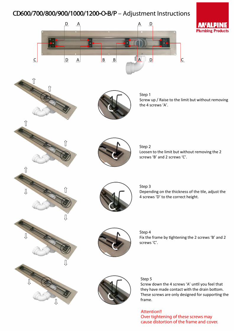
CD600/700/800/900/1000/1200-O-B/P – Adjustment Instructions
Step 1Screw up / Raise to the limit but without removing the 4 screws ‘A’.
Step 5Screw down the 4 screws ‘A’ until you feel that they have made contact with the drain bottom. These screws are only designed for supporting the frame.
Step 3Depending on the thickness of the tile, adjust the 4 screws ‘D’ to the correct height.
Step 4Fix the frame by tightening the 2 screws ‘B’ and 2 screws ‘C’.
Step 2Loosen to the limit but without removing the 2 screws ‘B’ and 2 screws ‘C’.
Attention!!Over tightening of these screws may cause distortion of the frame and cover.
49
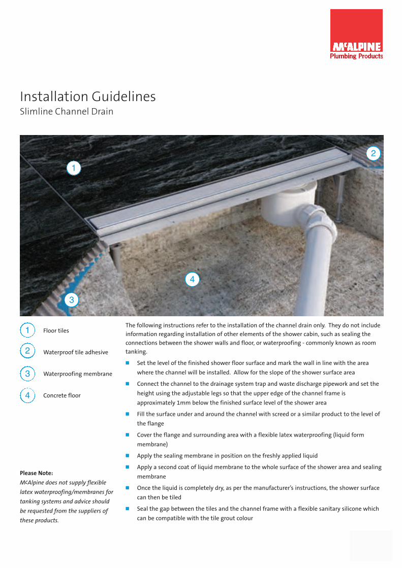
Installation GuidelinesSlimline Channel Drain
The following instructions refer to the installation of the channel drain only. They do not include
information regarding installation of other elements of the shower cabin, such as sealing the
connections between the shower walls and floor, or waterproofing - commonly known as room
tanking.
� Set the level of the finished shower floor surface and mark the wall in line with the area
where the channel will be installed. Allow for the slope of the shower surface area
� Connect the channel to the drainage system trap and waste discharge pipework and set the
height using the adjustable legs so that the upper edge of the channel frame is
approximately 1mm below the finished surface level of the shower area
� Fill the surface under and around the channel with screed or a similar product to the level of
the flange
� Cover the flange and surrounding area with a flexible latex waterproofing (liquid form
membrane)
� Apply the sealing membrane in position on the freshly applied liquid
� Apply a second coat of liquid membrane to the whole surface of the shower area and sealing
membrane
� Once the liquid is completely dry, as per the manufacturer’s instructions, the shower surface
can then be tiled
� Seal the gap between the tiles and the channel frame with a flexible sanitary silicone which
can be compatible with the tile grout colour
1
2
3
4
Floor tiles
Waterproof tile adhesive
Waterproofing membrane
Concrete floor
1
2
3
4
Please Note:
McAlpine does not supply flexible
latex waterproofing/membranes for
tanking systems and advice should
be requested from the suppliers of
these products.


![oõo 000 D '9 ñ B b a & b a & b b & b D a B b O D h] b -X & b D hJ … · oõo 000 D '9 ñ B b a & b a & b b & b D a B b O D h] b -X & b D hJ b O ... Author: 0001896288 Created Date:](https://static.fdocuments.net/doc/165x107/5c5dbd4609d3f2ca618b479b/ooo-000-d-9-n-b-b-a-b-a-b-b-b-d-a-b-b-o-d-h-b-x-b-d-hj-ooo-000.jpg)