C&D EXTENDED RUN TIME.pdf
7
C&D VRLA Batteries Extended Run Time for Small UPS Machines 41-7954 TECHNICAL BULLETIN 41-7954/0112/CD www.cdtechno.com
-
Upload
paul-rasmussen -
Category
Documents
-
view
233 -
download
0
Transcript of C&D EXTENDED RUN TIME.pdf

7/27/2019 C&D EXTENDED RUN TIME.pdf
http://slidepdf.com/reader/full/cd-extended-run-timepdf 1/6
C&D VRLA BatteriesExtended Run Time for
Small UPS Machines
41-7954TECHNICAL BULLETIN
41-7954/0112/CD www.cdtechno.com
7/27/2019 C&D EXTENDED RUN TIME.pdf
http://slidepdf.com/reader/full/cd-extended-run-timepdf 2/6
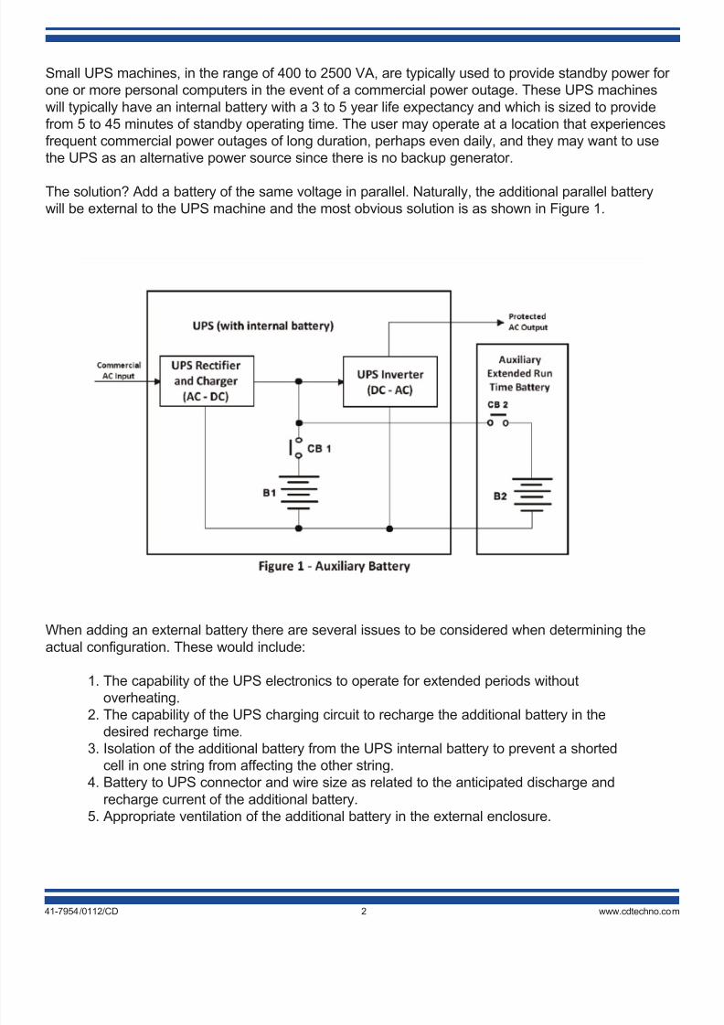
Small UPS machines, in the range of 400 to 2500 VA, are typically used to provide standby power for
one or more personal computers in the event of a commercial power outage. These UPS machines
will typically have an internal battery with a 3 to 5 year life expectancy and which is sized to provide
from 5 to 45 minutes of standby operating time. The user may operate at a location that experiences
frequent commercial power outages of long duration, perhaps even daily, and they may want to use
the UPS as an alternative power source since there is no backup generator.
The solution? Add a battery of the same voltage in parallel. Naturally, the additional parallel battery
will be external to the UPS machine and the most obvious solution is as shown in Figure 1.
41-7954/0112/CD 2 www.cdtechno.com
When adding an external battery there are several issues to be considered when determining the
actual configuration. These would include:
1. The capability of the UPS electronics to operate for extended periods without
overheating.
2. The capability of the UPS charging circuit to recharge the additional battery in thedesired recharge time.
3. Isolation of the additional battery from the UPS internal battery to prevent a shorted
cell in one string from affecting the other string.
4. Battery to UPS connector and wire size as related to the anticipated discharge and
recharge current of the additional battery.
5. Appropriate ventilation of the additional battery in the external enclosure.

7/27/2019 C&D EXTENDED RUN TIME.pdf
http://slidepdf.com/reader/full/cd-extended-run-timepdf 3/641-7954/0112/CD 3 www.cdtechno.com
The configuration as shown in Figure 1 is certainly the easiest to implement, however, it does assume
that the UPS rectifier has the ampere output capability to power the inverter, recharge the internal
battery and in addition, recharge the auxiliary battery. For this configuration and that of Figure 2, the
UPS rectifier should have a minimum reserve current of 2 amperes per 100 ampere-hours of capacity
of the auxiliary battery. This minimum reserve current should provide for recharge of the auxiliary
battery within a 72-hour period.
If the current capability of the UPS internal rectifier is marginal, the recharge current to the batteries
can be limited with resistors (R1 & R2) as noted in Figure 2. For example, assume a UPS rectifier had
only 2 amperes available for charging a self contained 10 ampere-hour capacity battery and that a
40 ampere-hour battery were being added in parallel as an external battery. In this case the limited
available charging current should be divided between the two batteries in proportion to their
capacities. In this case, 1/5 of the recharge current (0.4 amperes) should be supplied to the internal
10 ampere-hour battery and 4/5 or the recharge current (1.6 amperes) to the external 40
ampere-hour battery. The current limiting resistor values would be calculated as that required to limit
the inrush current to the desired value when the full charging voltage is applied to the discharged
battery while at it's open circuit value. The value of the resistors heat dissipation capability (wattage)
would be simply the product of the voltage drop multiplied by the maximum current (V*I) or themaximum current squared multiplied by the resistance (I2R).
For example, assume the charging voltage is 2.3 volts per cell for a 24-cell system or 55.2 VDC.
The worse case is when the discharged battery open circuit voltage would be 1.96 volts per cell or 47
VDC for a 24-cell system. The internal 10 ampere-hour battery current limiting resistor values would
be calculated as:
R1 = (55.2 - 47) VDC/0.4 amperes
R1 = 20.5 Ohms

7/27/2019 C&D EXTENDED RUN TIME.pdf
http://slidepdf.com/reader/full/cd-extended-run-timepdf 4/6
WR1= (55.2 - 47) VDC x 0.4 amperes
WR1 = 3.25 watts minimum
The external 40 ampere-hour battery current limiting resistor values would be calculated as:
R2 = (55.2 - 47) VDC/1.6 amperes
R2 = 5.1 Ohms
WR2= (55.2 - 47) VDC x 1.6 amperes
WR2 = 13.1 watts minimum
During discharge the batteries will supply power through the diodes D1 and D2 thus eliminating the
voltage drop that would otherwise have occurred through R1 and R2.
While other approaches to the current limiting feature are possible, use of the resistor is perhaps the
simplest and least expensive, however, it will increase the recharge time. Also, if resistive current
limiting is employed, the heat-producing resistor should not be mounted near the battery.
Although the configuration of Figure 1 and 2 will work, they have one significant common deficiency:they do not provide for mutual isolation of the two battery systems. As a result, if there should be a
shorted cell in one battery it will discharge the other battery connected in parallel. This can be a
significant problem especially when the two-battery systems have different life expectancies or use
histories. This deficiency can be corrected as shown in Figure 3.
In this configuration the resistors R1 and R2 limit the charging current to each of the two batteries
as they did in Figure 2 however the action of D1, D2 and D4 prevent a short in either battery from
discharging the other battery.
41-7954/0112/CD 4 www.cdtechno.com

7/27/2019 C&D EXTENDED RUN TIME.pdf
http://slidepdf.com/reader/full/cd-extended-run-timepdf 5/6
When the UPS internal charger does not have sufficient ampere capability to recharge the auxiliary
battery in a reasonable time it will be necessary to include an auxiliary charger in the external
package. This configuration would be similar to that shown in Figure 4. As shown, using the normally
closed contacts of the commercial power relay (or a solid state switch), the auxiliary battery andcharger are completely isolated from the UPS until such time as there is a commercial power failure.
Upon the commercial power failure the relay K1 will deenergize and the normally closed (NC)
contacts will close placing the auxiliary battery in parallel with the UPS internal battery.
The commercial power relay K1 can be omitted if the UPS internal battery charging voltage is
adjusted to a value slightly higher (e.g. 2.3 v/c) than that used on the auxiliary battery (e.g. 2.25 v/c).
In this situation diode D2 would be reverse biased until such time that there was a commercial power
failure when it would be forward biased and route it's share of the load current to the UPS inverter.
The arrangement of diodes D1 and D2 also isolate the two battery systems preventing a shorted cell
in one string from affecting the other string. This is perhaps the most simple of all the configurations
however, the relative settings of the chargers output voltages is critical.
Table 1 identifies the approximate 20 hour rated ampere hour capacity of the battery required to
provide the noted operating time for UPS systems of the noted VA rating, power factor (pf), DC-AC
inverter efficiency and DC buss voltage.
41-7954/0112/CD 5 www.cdtechno.com

7/27/2019 C&D EXTENDED RUN TIME.pdf
http://slidepdf.com/reader/full/cd-extended-run-timepdf 6/6
When adding parallel strings of batteries of the same voltage, each of the strings should be
separately cabled to the common tie point and should include individual string overcurrent protection.
Any data, descriptions or specifications presented herein are subject to revision by C&D Technologies, Inc.without notice. While such information is believed to be accurate as indicated herein, C&D Technologies, Inc.makes no warranty and hereby disclaims all warranties, express or implied, with regard to the accuracy or completeness of such information. Further, because the product(s) featured herein may be used under conditionsbeyond its control, C&D Technologies, Inc. hereby disclaims all warranties, either express or implied, concerningthe fitness or suitability of such product(s) for any particular use or in any specific application or arising from any
course of dealing or usage of trade. The user is solely responsible for determining the suitability of the product(s)featured herein for user’s intended purpose and in user’s specific application.
Copyright 2012 C&D TECHNOLOGIES, INC. Printed in U.S.A. 41-7954 0112/CD
1400 Union Meeting RoadP.O. Box 3053 • Blue Bell, PA 19422-0858(215) 619-2700 • Fax (215) 619-7899 • (800) [email protected]
1 Hour 2 Hours 3 Hours 4 Hours
500 12 65% 615.4 102.6 85 150 200 250
24 65% 615.4 51.3 43 75 100 125
36 70% 571.4 31.7 26 46 62 77
48 75% 533.3 22.2 18 33 43 54
72 75% 533.3 14.8 12 22 29 36
120 80% 500.0 8.3 7 12 16 20
1000 12 65% 1230.8 205.1 170 300 400 500
24 65% 1230.8 102.6 85 150 200 250
36 70% 1142.9 63.5 53 93 124 155
48 75% 1066.7 44.4 37 65 87 108
72 75% 1066.7 29.6 25 43 58 72
120 80% 1000.0 16.7 14 24 33 41
1500 12 65% 1846.2 307.7 255 450 600 750
24 65% 1846.2 153.8 128 225 300 375
36 70% 1714.3 95.2 79 139 186 232
48 75% 1600.0 66.7 55 98 130 163
72 75% 1600.0 44.4 37 65 87 108
120 80% 1500.0 25.0 21 37 49 61
2000 12 65% 2461.5 410.3 340 600 800 1000
24 65% 2461.5 205.1 170 300 400 500
36 70% 2285.7 127.0 105 186 248 310
48 75% 2133.3 88.9 74 130 173 217
72 75% 2133.3 59.3 49 87 116 144
120 80% 2000.0 33.3 28 49 65 81
144 85% 1882.4 26.1 22 38 51 64
2500 12 65% 3076.9 512.8 425 750 1000 1250
24 65% 3076.9 256.4 213 375 500 625
36 70% 2857.1 158.7 132 232 310 387
48 75% 2666.7 111.1 92 163 217 271
72 75% 2666.7 74.1 61 108 144 181
120 80% 2500.0 41.7 35 61 81 102
144 85% 2352.9 32.7 27 48 64 80
Approxomate Hours Operation Per
Rated Battery Ampere-Hour Capacity
Assumed
AC-DC
Efficiency
UPS-VA
Rating
@ 0.8 p.f.
DC Buss
Voltage
Battery
Watts
Battery
Watts
per Cell
Table 1 - Ah Battery Capacity for Specified Run Time


