CD-DD4500 Operation Manual - Sharp...
48
Thank you for purchasing this SHARP product. To obtain the best performance from this product, please read this manual carefully. It will guide you in operating your SHARP product. CD-DD4500 Mini Component System consisting of CD-DD4500 (main unit), CP-DD4500 (Front), center (GBOXS0064AWM1), surround (R) (GBOXS2008AWM1) and surround (L) (GBOXS4008AWM1) speaker sys- tem. MINI COMPONENT SYSTEM MODEL CD-DD4500 OPERATION MANUAL
-
Upload
truongthien -
Category
Documents
-
view
221 -
download
2
Transcript of CD-DD4500 Operation Manual - Sharp...

Thank you for purchasing this SHARP product.To obtain the best performance from this product, please read thismanual carefully. It will guide you in operating your SHARP product.
CD-DD4500 Mini Component System consisting of CD-DD4500 (main unit),CP-DD4500 (Front), center (GBOXS0064AWM1), surround (R)(GBOXS2008AWM1) and surround (L) (GBOXS4008AWM1) speaker sys-tem.
MINI COMPONENT SYSTEM
MODEL
CD-DD4500OPERATION MANUAL

2
Special NotesNOTEThis equipment has been tested and found to comply with the limits for a Class Bdigital device, pursuant to Part 15 of the FCC Rules.These limits are designed to provide reasonable protection against harmful interfer-ence in a residential installation.This equipment generates, uses, and can radiate radio frequency energy and, if notinstalled and used in accordance with the instructions, may cause harmful interferenceto radio communications.However, there is no guarantee that interference will not occur in a particular installa-tion. If this equipment does cause harmful interference to radio or television reception,which can be determined by turning the equipment off and on, the user is encouragedto try to correct the interference by one or more of the following measures:
Reorient or relocate the receiving antenna.Increase the separation between the equipment and receiver.Connect the equipment into an outlet on a circuit different from that to which thereceiver is connected.Consult the dealer or an experienced radio/TV technician for help.
WARNINGFCC Regulations state that any unauthorized changes or modifications to this equip-ment not expressly approved by the manufacturer could void the user’s authority tooperate this equipment.
NOTEIt is the intent of Sharp that this product be used in full compliance with the copyrightlaws of the United States and that prior permission be obtained from copyright ownerswhenever necessary.
Impo
rtan
t Ins
truc
tion
– S
peci
al N
otes
–
FOR YOUR RECORDSFor your assistance in reporting this unit in case of loss or theft, please recordbelow the model number and serial number which are located on the rear of theunit.Please retain this information.
Model number .................................................................................
Serial number .................................................................................
Date of purchase .................................................................................
Place of purchase .................................................................................
0005
CAUTION: TO REDUCE THE RISK OF ELECTRIC SHOCK, DO NOTREMOVE COVER (OR BACK).NO USER-SERVICEABLE PARTS INSIDE. REFER SERVICING TOQUALIFIED SERVICE PERSONNEL.
Explanation of Graphical Symbols:
The lightning flash with arrowhead symbol, within anequilateral triangle, is intended to alert the user to thepresence of uninsulated “dangerous voltage” within theproduct’s enclosure that may be of sufficient magnitudeto constitute a risk of electric shock to persons.
The exclamation point within an equilateral triangle isintended to alert the user to the presence of importantoperating and maintenance (servicing) instructions inthe literature accompanying the appliance.
0005
Caution - use of controls or adjustments or performance of proce-dures other than those specified herein may result in hazardous ra-diation exposure.
0005
WARNING: TO REDUCE THE RISK OF FIRE OR ELECTRICSHOCK, DO NOT EXPOSE THIS APPLIANCE TO RAIN ORMOISTURE.
0005
Manufactured under license from Dolby Laboratories.“Dolby,” “Pro Logic,” and the double-D symbol are trademarks of Dolby Laboratories.Confidential unpublished works. © 1992-1997 Dolby Laboratories. All rights reserved.
3
CD-DD4500
1
2
3
4
5
6
7
8
9
10
11
12
13
14
15
CAUTIONAll the safety and operating instructions should be read before the appliance isoperated, and should be retained for future reference.Electrical energy can perform many useful functions. This unit has been engineeredand manufactured to assure your personal safety. Improper use can result inpotential electrical shock or fire hazards. In order not to defeat the safeguards,observe the following basic rules for its installation, use and servicing.
1 Heed Warnings - All warnings on the appliance and in the operating instructionsshould be adhered to.
2 Follow Instructions - All operating and use instructions should be followed.
3 Water and Moisture - The appliance should not be used near water - forexample, near a bathtub, washbowl, kitchen sink, laundry tub, in a wet base-ment, or near a swimming pool, etc.
4 Carts and Stands - The appliance should be used only with a cart or stand that isrecommended by the manufacturer.● An appliance and cart combination should be moved with care.
Quick stops, excessive force, and uneven surfaces may causethe appliance and cart combination to overturn.
5 Wall or Ceiling Mounting - The appliance should be mounted to a wall or ceilingonly as recommended by the manufacturer.
6 Ventilation - The appliance should be situated so that its location or position doesnot interfere with its proper ventilation. For example, the appliance should not besituated on a bed, sofa, rug, or similar surface that may block the ventilationopenings; or, placed in a built-in installation, such as a bookcase or cabinet thatmay impede the flow of air through the ventilation openings.
7 Heat - The appliance should be situated away from heat sources such asradiators, heat registers, stoves, or other appliances (including amplifiers)that produce heat.
8 Power Sources - The appliance should be connected to a power supply only ofthe type described in the operating instructions or as marked on the appliance.
9 Power-Cord Protection - Power-supply cords should be routed so that they arenot likely to be walked on or pinched by items placed upon or against them,paying particular attention to cords at plugs, convenience receptacles, and thepoint where they exit from the appliance.
10 Do not use liquid cleaners or aerosol cleaners. Use a damp cloth for cleaning.
11 Power Lines - An outdoor antenna should be located away from power lines.
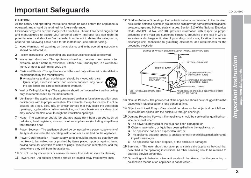
12 Outdoor Antenna Grounding - If an outside antenna is connected to the receiver,be sure the antenna system is grounded so as to provide some protection againstvoltage surges and built-up static charges. Section 810 of the National ElectricalCode, ANSI/NFPA No. 70-1984, provides information with respect to propergrounding of the mast and supporting structure, grounding of the lead-in wire toan antenna discharge unit, size of grounding conductors, location of antenna-discharge unit, connection to grounding electrodes, and requirements for thegrounding electrode.
ANTENNA LEAD IN WIRE
ANTENNA DISCHARGE UNIT(NEC SECTION 810-20)
POWER SERVICE GROUNDING ELECTRODE SYSTEM(NEC ART 250, PART H)
GROUNDING CONDUCTORS(NEC SECTION 810-21)
GROUND CLAMPS
NEC - NATIONAL ELECTRICAL CODES2898A
ELECTRIC SERVICE EQUIPMENT
GROUND CLAMP
EXAMPLE OF ANTENNA GROUNDING AS PER NATIONAL ELECTRICAL CODE
13 Nonuse Periods - The power cord of the appliance should be unplugged from theoutlet when left unused for a long period of time.
14 Object and Liquid Entry - Care should be taken so that objects do not fall andliquids are not spilled into the enclosure through openings.
15 Damage Requiring Service - The appliance should be serviced by qualified ser-vice personnel when:A The power-supply cord or the plug has been damaged; orB Objects have fallen, or liquid has been spilled into the appliance; orC The appliance has been exposed to rain; orD The appliance does not appear to operate normally or exhibits a marked change
in performance; orE The appliance has been dropped, or the enclosure damaged.
16 Servicing - The user should not attempt to service the appliance beyond thatdescribed in the operating instructions. All other servicing should be referred toqualified service personnel.
17 Grounding or Polarization - Precautions should be taken so that the grounding orpolarization means of an appliance is not defeated.
0005
Important Safeguards
Impo
rtan
t Ins
truc
tion
– Im
port
ant S
afeg
uard
s –

4
General Information PageAccessories ......................................................................................... 4Precautions ......................................................................................... 5Controls and Indicators ................................................................6 - 9
Preparation for UseSystem Connections .................................................................. 10, 11Speakers ...................................................................................... 12, 13Remote Control ................................................................................. 14
Basic OperationGeneral Control ................................................................................. 15Sound Control ................................................................................... 16Setting the Clock .............................................................................. 17
CD PlaybackListening to a CD (CDs) .............................................................18 - 20Repeat or Random Play ................................................................... 20Programmed Play ............................................................................. 21
RadioListening to the Radio ...................................................................... 22Listening to the Memorized Station ................................................ 23
Contents
Tape Playback PageListening to a Cassette Tape (TAPE 1 or TAPE 2) .......................... 24
Tape RecordingRecording from the Radio ................................................................ 25Recording from a CD (CDs) ............................................................. 26Dubbing from Tape to Tape .............................................................. 27
Surround OperationDolby Digital ...................................................................................... 28Enjoy the Surround Sound ........................................................ 29, 30Changing the Speaker Setting ................................................. 31 - 34Description of Terminology ............................................................. 35
Advanced FeaturesTimer and Sleep Operation ........................................................ 36, 37Enhancing Your System ............................................................. 38, 39
ReferencesTroubleshooting Chart ..............................................................40 - 42Maintenance ...................................................................................... 43Specifications ............................................................................. 44, 45
CONSUMER LIMITED WARRANTY ..................................... Back cover
Accessories
Please confirm that the following accessories are included.
Remote control × 1(RRMCG0296AWSA)
FM/AM loop antenna × 1(QANTL0007AWZZ)
Note:Only the above accessories are included.
Gen
eral
Info
rmat
ion
– C
onte
nts
/ Acc
esso
ries
–
*CD_DD4500_P04_09 2001.4.19, 11:42 PM4

5
CD-DD4500
1
2
3
4
5
6
7
8
9
10
11
12
13
14
15
Precautions
GeneralPlease ensure that the equipment is positioned in a well ventilated area andensure that there is as least 4" (10 cm) of free space along the sides, top andback of the unit.
Use the unit on a firm, level surface free from vibration.
Keep the unit away from direct sunlight, strongmagnetic fields, excessive dust, humidity and elec-tronic/electrical equipment (home computers, fac-similes, etc.) which generates electrical noise.
Do not place anything on top of the unit.
Do not expose the unit to moisture, to temperatures higher than 140°F (60°C)or to extreme low temperatures.
If your system does not work properly, disconnect the AC power cord from theAC outlet. Plug the AC power cord back in, and then turn on your system.
In case of an electrical storm, unplug the unit for safety.
Hold the AC power plug by the head when removing itfrom the AC outlet, as pulling the cord can damageinternal wires.
Do not remove the outer cover, as this may resultin electric shock. Refer internal service to your lo-cal SHARP service facility.
This unit should only be used within the range of 41°F - 95°F (5°C - 35°C).
Warning:The voltage used must be the same as that specified on this unit.Using this product with a higher voltage other than that which is specified is dan-gerous and may result in a fire or other type of accident causing damage. SHARPwill not be held responsible for any damage resulting from use of this unit with avoltage other than that which is specified.
Volume controlThe sound level at a given volume setting depends on speaker efficiency, locationand various other factors.It is advisable to avoid exposure to high volume levels, which occur while turningthe unit on with the volume control setting up high, or while continually listening athigh volumes.
Care of compact discsCompact discs are fairly resistant to damage, however mistracking can occur dueto an accumulation of dirt on the disc surface.Follow the guidelines below for maximum enjoyment from your CD collection andplayer.
Do not write on either side of the disc, particularly the non-label side fromwhich signals are read.Do not mark this surface.Keep your discs away from direct sunlight, heat, and excessive moisture.Always hold the CDs by the edges. Fingerprints, dirt, or water on the CDs cancause noise or mistracking. If a CD is dirty or does not play properly, clean itwith a soft, dry cloth, wiping straight out from the center, along the radius.
4” (10 cm) 4” (10 cm) 4” (10 cm)
4” (10 cm)
NO YEScorrect G
ener
al In
form
atio
n–
Pre
caut
ions
–
*CD_DD4500_P04_09 2001.4.19, 11:42 PM5

6
Controls and Indicators
Front panel Reference page
01. Disc Tray .......................................................................................... 1802. Surround Effect Buttons .......................................................... 29, 3003. Timer Set Indicator .......................................................................... 3704. Power On/Stand-by Button ................................................ 15, 36, 4105. Tape 2 Cassette Compartment ................................................. 24, 2706. Tape 1 Cassette Compartment ................................................. 24, 2707. Equalizer Mode Select Button ........................................................ 1608. Volume Control .......................................................................... 16, 3609. Extra Bass/Demo Mode Button .......................................... 15, 16, 4110. Disc Tray Open/Close Button ......................................................... 1811. Disc Number Select Buttons .............................................. 18, 21, 2612. Disc Skip Button ............................................................................. 1813. Tuning and Time Up Button ............................................... 17, 22, 3614. CD or Tape Stop Button (with Indicator) ................................. 19, 2415. CD Button .................................................................................. 18, 2616. Tuner (Band) Button ....................................................................... 2217. Tape (1 V V V V V 2) Button .................................................................. 24, 2718. DVD/VCR Button ....................................................................... 28, 3919. Dimmer Button ................................................................................ 1520. Clock Button .............................................................................. 17, 3621. Timer/Sleep Button ......................................................................... 3622. Headphone Jack .............................................................................. 3923. CD Play or Repeat, Tape Play Button
(with Indicator) ...................................................... 19, 20, 24 - 27, 4124. CD Fast Forward, Tape 2 Fast Forward
or Tuner Preset Up Button ............................................... 19, 21 - 2425. Tuning and Time Down Button .......................................... 17, 22, 3626. Memory/Set Button ....................................................... 17, 21, 23, 3627. Tape 2 Record Pause Button ........................................... 25 - 27, 3928. CD Fast Reverse, Tape 2 Rewind
or Tuner Preset Down Button .......................................... 19, 21 - 24
5
6
7 8
1
2
3
4
9 10
11
12
1923
181716151413
25 26 27 28
2420
2122
Gen
eral
Info
rmat
ion
– C
ontr
ols
and
Indi
cato
rs –
Description of remote control (See page 8.)
*CD_DD4500_P04_09 2001.4.19, 11:42 PM6

7
CD-DD4500
1
2
3
4
5
6
7
8
9
10
11
12
13
14
15
Display01. Left Front Speaker Indicator02. Low Frequency Effect Indicator03. Center Speaker Indicator04. Right Front Speaker Indicator05. Subwoofer Indicator06. Left Surround Speaker Indicator07. Surround Indicator08. Right Surround Speaker Indicator09. Extra Bass Indicator10. Tape 2 Record Indicator11. CD Repeat Indicator12. Disc Number Indicators13. FM Stereo Receiving Indicator14. FM Stereo Mode Indicator15. Sleep Indicator16. Dolby Pro Logic Indicator17. Memory Indicator18. CD Random Play Indicator19. CD Play Indicator20. CD Pause Indicator21. Tape Play Indicator22. CD Music Schedule Indicators23. Timer Recording Indicator24. Timer Play Indicator25. Dolby Digital Indicator26. Dolby Virtual Indicator
Rear panel Reference page
01. DVD Digital Input Jack .................................................................... 3802. Center Speaker Jacks ............................................................... 10, 1103. Surround Speaker Jacks .......................................................... 10, 1104. FM/AM Loop Antenna Jack ...................................................... 10, 1105. Video/Auxiliary (Audio Signal) Input Jacks .................................. 3806. Speaker Terminals .................................................................... 10, 1107. Subwoofer Pre Output Jack ........................................................... 3808. AC Power Cord ................................................................................ 10
1
8
2
34
56
7
26
9
1718
19 20 22 23 24 25
1011 13 14 15 16
21
1 2 3
6 7 8
5 5
12
4
Gen
eral
Info
rmat
ion
– C
ontr
ols
and
Indi
cato
rs –
*CD_DD4500_P04_09 2001.4.19, 11:42 PM7

8
Controls and Indicators (continued)
Remote control Reference page
01. Remote Control Transmitter02. CD Memory Button
03. Set Up Menu Select Buttons .................................................. 31 - 3404. Menu Button .............................................................................31 - 3405. Item Button ...............................................................................31 - 3406. Disc Number Select Buttons07. CD Random Button ......................................................................... 2008. CD Pause Button ............................................................................. 1909. CD Fast Reverse/Preset Down Button10. CD Stop Button11. Tape 2 Record Pause Button
12. Tuner (Band) Button13. CD Button14. Extra Bass Button
15. CD Clear Button .............................................................................. 2116. Power Button17. Surround Effect Buttons
18. Equalizer Mode Select Button19. CD Play or Repeat Button20. CD Fast Forward/Preset Up Button
21. Tape 1/Tape 2 Play Button22. Tape 1/Tape 2 Stop Button23. Tape 2 Fast Forward Button
24. Tape 2 Rewind Button25. DVD/VCR Button26. Tape (1 V 2) Button
27. Volume Up or Down Buttons
112 15
16
17
20
3
56789
13
14
121110
4
21
272625242322
1819
✱
✱✱
✱✱
✱
Gen
eral
Info
rmat
ion
– C
ontr
ols
and
Indi
cato
rs –
Buttons with “✱” mark in the illustration can be operated with the remote controlonly.Other buttons can be operated on the main unit and the remote control.
Battery installation for remote control (See page 14.)
*CD_DD4500_P04_09 2001.4.19, 11:42 PM8
9
CD-DD4500
1
2
3
4
5
6
7
8
9
10
11
12
13
14
15
Speaker system
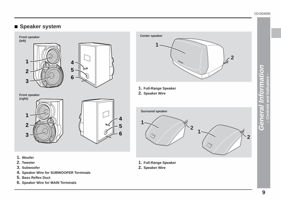
01. Woofer02. Tweeter03. Subwoofer04. Speaker Wire for SUBWOOFER Terminals05. Bass Reflex Duct06. Speaker Wire for MAIN Terminals
Front speaker(left)
Front speaker(right)
Gen
eral
Info
rmat
ion
– C
ontr
ols
and
Indi
cato
rs –
2
1
3
2
1
3
456
456
2
1
Center speaker
21
Surround speaker
01. Full-Range Speaker02. Speaker Wire
01. Full-Range Speaker02. Speaker Wire
21
*CD_DD4500_P04_09 2001.4.19, 11:42 PM9
10
��������
����������
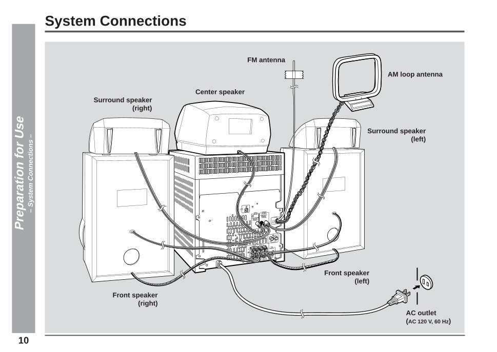
System Connections
FM antenna
Front speaker(left)
AC outlet(AC 120 V, 60 Hz)
Pre
para
tion
for
Use
– S
yste
m C
onne
ctio
ns –
AM loop antenna
Front speaker(right)
Surround speaker(left)
Surround speaker(right)
Center speaker
*CD_DD4500_P10_14 2001.4.19, 11:41 PM10

11
CD-DD4500
1
2
3
4
5
6
7
8
9
10
11
12
13
14
15
Connections (continued)
Speaker connectionFront speakersMain terminals:Connect the black wire to MAIN(–) terminal and the blue wire to the MAIN(+) terminal.Subwoofer terminals:Connect the black wire to the SUBWOOFER(–) terminal and the red wire to theSUBWOOFER(+) terminal.
Incorrect�
Caution:Never mistake the MAIN and the SUBWOOFER terminals.The unit or the speakers may be damaged.Only the included speakers should be used with this product.Do not use other speakers with this unit or use the supplied speak-ers with other units.Do not mistake the right and the left channels.The right speaker is the one on the right side when you face the unit.Do not let the bare speaker wires touch each other.Do not stand or sit on the speakers. You may be injured.Do not mistake the conection of center and surround speakers.
Pre
para
tion
for
Use
– S
yste
m C
onne
ctio
ns –
Demonstration mode (See page 15.)
Center speakerConnect the center speaker wire to the CENTER SPEAKER jack as shown.Use speakers with an impedance of 6 ohms or more, as lower impedance speakerscan damage the unit.
CENTER
Black
Surround speakersConnect each surround speaker wire to the SURROUND SPEAKER jack as shown.Use speakers with an impedance of 8 ohms or more, as lower impedance speakerscan damage the unit.
SURROUNDSURROUND
WhiteRed
LR
Right Left
FM/AM loop antenna connectionConnect the FM/AM loop antenna to the ANTENNA jack.
Position the FM antenna wire and rotate the AM loop antenna for optimum reception.Place the AM loop antenna on a shelf, or attach it to a stand or a wall.Notes:
Placing the antenna on the unit or near the AC power cord may cause noise pickup.Place the antenna away from the unit for better reception.Do not connect the attached FM antenna to an external FM antenna. Otherwise,trouble may occur.
Installing the AM loop antenna:< Assembling >
< Attaching to the wall >
Screws(not supplied)
Wall
Red
Black
Blue
Black
Red
Black
Blue
Black
LeftRight
*CD_DD4500_P10_14 2001.4.19, 11:41 PM11
12
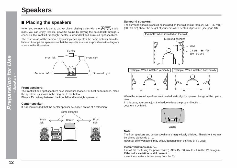
Surround speakers:The surround speakers should be installed on the wall. Install them 23-5/8" - 35-7/16"(60 - 90 cm) above the height of your ears when seated, if possible (see page 13).
When the surround speakers are installed vertically, the speaker badge will be upsidedown.In this case, you can adjust the badge to face the proper direction.Just turn it by hand.
Note:The front speakers and center speaker are magnetically shielded. Therefore, they maybe placed alongside a TV.However color variations may occur, depending on the type of TV used.
If color variations occur ....turn off the TV (using the power switch). After 15 - 30 minutes, turn the TV on again.If the color variation is still present ...move the speakers further away from the TV.
Pre
para
tion
for
Use
– S
peak
ers
–
Placing the speakersWhen you connect this unit to a DVD player playing a disc with the trade-mark, you can enjoy realistic, powerful sound by playing the soundtrack through 5channels; the front left, front right, center, surround left and surround right speakers.
The best sound will be achieved by placing each speaker the same distance from thelistener. Arrange the speakers so that the layout is as close as possible to the diagramshown in this illustration.
Front speakers:The front left and right speakers have individual shapes. For best performance, placethe speakers as shown in the diagram to the below.Place a TV halfway between the front left and front right speakers.
Center speaker:It is recommended that the center speaker be placed on top of a television.
Badge
Speakers
Example: When installed on the wall
Surround speaker
Wall
23-5/8" - 35-7/16"(60 - 90 cm)
Example: When installed vertically Example: When installed horizontally
Front left
Center
Front right
Surround left Surround right
Same distance
Frontleft
Center Frontright
*CD_DD4500_P10_14 2001.4.19, 11:41 PM12

13
CD-DD4500
1
2
3
4
5
6
7
8
9
10
11
12
13
14
15
Pre
para
tion
for
Use
– S
peak
ers
–
Connecting the AC power cordAfter checking all the connections have been made correctly, plug the ACpower cord of this unit into the AC outlet. If you plug in the unit first, the unitwill enter the demonstration mode (see page 15).
Note:Unplug the unit if it will not be used for a prolonged period of time.
To install the surround speakers on the wallSharp designed the surround speakers so you may hang them on the wall.Be sure to use the correct type and size of screw, as shown below.
1. Drive one screw into the wall for each speaker, as shown in the illus-tration.
Make sure that both the screw and the wall can support a load of 45 lbs. (20 kg).Drive the screws, so the screw head extends about 3/16" (5 mm) out from thewall.
2. Install the surround speakers on the wall by inserting the screw headsinto the slots on the back of the speakers.
Power amplifier
Mid-to-high range (200 Hz - 20 kHz)
Ultra-low range (60 Hz - 200 Hz)
Pre-amplifier
Pre-amplifier
Power amplifier
L-chTweeter
Woofer
Subwoofer
Speakers (continued)
Bi-amp system:Each speaker unit has a built-in subwoofer (low frequency range) which is driven sepa-rately from the woofer and tweeter (mid-to-high frequency range). Two independentamplifiers which have individual frequency characteristics are used.By amplifying separately the two frequency bands, clearer sound is achieved.
1/8" (3.2 mm)
3/16" (5 mm)
Min. 7/8" (22 mm)
3/8" (9 mm)
3/16" (5 mm)
Wall mounting screw
Min. 11/16" (17 mm)Wall surface
Wall surface
*CD_DD4500_P10_14 2001.4.19, 11:41 PM13

14
Battery installationUse 2 “AA” size batteries (UM/SUM-3, R6, HP-7 or similar).Batteries are not included.
1. Remove the battery cover.2. Insert the batteries according to the direction indicated in the bat-
tery compartment.When inserting or removing the batteries, push them toward the ë battery termi-nals.
3. Replace the cover.
Precautions for battery use:Replace all old batteries with new ones at the same time.Do not mix old and new batteries.Remove the batteries if the unit will not be used for long periods of time. This willprevent potential damage due to battery leakage.
Caution:Do not use rechargeable batteries (nickel-cadmium battery, etc.).Installing the batteries incorrectly may cause the unit to malfunction.
Notes concerning use:Replace the batteries if the operating distance is reduced or if the operation be-comes erratic.Periodically clean the transmitter on the remote control and the sensor on the unitwith a soft cloth.Exposing the sensor on the unit to strong light may interfere with operation. Changethe lighting or the direction of the unit.Keep the remote control away from moisture, heat, shock, and vibrations.
Test of the remote controlFace the remote control directly to the remote sensor on the unit.
The remote control can be used within the range shown below:Press the POWER button. Does the power turn on? Now, you can enjoy the music.
Remote Control
8" - 20'(0.2 m - 6 m)
Remote sensor
Pre
para
tion
for
Use
– R
emot
e C
ontr
ol –
*CD_DD4500_P10_14 2001.4.19, 11:41 PM14

15
CD-DD4500
1
2
3
4
5
6
7
8
9
10
11
12
13
14
15
Demonstration modeThe first time the unit is plugged, the unit will enter the demonstration mode. You willsee words scroll.
To cancel the demonstration mode:When the unit is in the power stand-by mode (demonstration mode), press the X-BASS/DEMO button.The demonstration mode will be canceled and the display will disappear.
To return to the demonstration mode:When the unit is in the power stand-by mode, press the X-BASS/DEMO button again.
Note:When the power is on, the X-BASS/DEMO button can be used to select the extra bassmode.
General Control
Bas
ic O
pera
tion
– G
ener
al C
ontr
ol –
Display brightness (2 levels)You can switch the display brightness by pressing the DIMMER button.
BrightenedDimmed
To turn the power onPress the POWER button to turn the power on.
To set the unit to stand-by mode:Press the POWER button again.
*CD_DD4500_P15_17 2001.4.16, 6:59 PM15
16
Sound Control
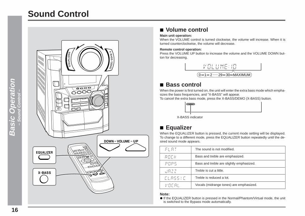
Volume controlMain unit operation:When the VOLUME control is turned clockwise, the volume will increase. When it isturned counterclockwise, the volume will decrease.
Remote control operation:Press the VOLUME UP button to increase the volume and the VOLUME DOWN but-ton for decreasing.
Bass controlWhen the power is first turned on, the unit will enter the extra bass mode which empha-sizes the bass frequencies, and “X-BASS” will appear.To cancel the extra bass mode, press the X-BASS/DEMO (X-BASS) button.
EqualizerWhen the EQUALIZER button is pressed, the current mode setting will be displayed.To change to a different mode, press the EQUALIZER button repeatedly until the de-sired sound mode appears.
0 1 2 29 30 MAXIMUM.....
X-BASS indicator
The sound is not modified.
Bass and treble are emphasized.
Bass and treble are slightly emphasized.
Treble is cut a little.
Treble is reduced a lot.
Vocals (midrange tones) are emphasized.
Bas
ic O
pera
tion
– S
ound
Con
trol
–
Note:If the EQUALIZER button is pressed in the Normal/Phantom/Virtual mode, the unitis switched to the Bypass mode automatically.
*CD_DD4500_P15_17 2001.4.16, 7:00 PM16
17
CD-DD4500
1
2
3
4
5
6
7
8
9
10
11
12
13
14
15
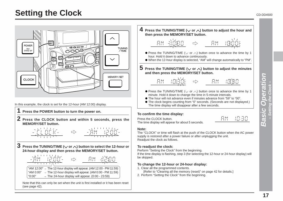
To confirm the time display:Press the CLOCK button.The time display will appear for about 5 seconds.
Note:The “CLOCK” or time will flash at the push of the CLOCK button when the AC powersupply is restored after a power failure or after unplugging the unit.Readjust the clock as follows.
To readjust the clock:Perform “Setting the Clock” from the beginning.If the time display is flashing, step 3 (for selecting the 12-hour or 24-hour display) willbe skipped.
To change the 12-hour or 24-hour display:1. Clear all the programmed contents. [Refer to “Clearing all the memory (reset)” on page 42 for details.]2. Perform “Setting the Clock” from the beginning.
Setting the Clock
In this example, the clock is set for the 12-hour (AM 12:00) display.
1 Press the POWER button to turn the power on.
2 Press the CLOCK button and within 5 seconds, press theMEMORY/SET button.
3 Press the TUNING/TIME ( X X X X X or WWWWW) button to select the 12-hour or24-hour display and then press the MEMORY/SET button.
4 Press the TUNING/TIME ( X X X X X or WWWWW) button to adjust the hour andthen press the MEMORY/SET button.
Press the TUNING/TIME (X or W) button once to advance the time by 1hour. Hold it down to advance continuously.When the 12-hour display is selected, “AM” will change automatically to “PM”.
5 Press the TUNING/TIME ( X X X X X or WWWWW) button to adjust the minutesand then press the MEMORY/SET button.
Press the TUNING/TIME (X or W) button once to advance the time by 1minute. Hold it down to change the time in 5-minute intervals.The hour will not advance even if minutes advance from “59” to “00”.The clock begins counting from “0” seconds. (Seconds are not displayed.)The time display will disappear after a few seconds.
Bas
ic O
pera
tion
– S
ettin
g th
e C
lock
–
Note that this can only be set when the unit is first installed or it has been reset(see page 42).
“AM 12:00”→ The 12-hour display will appear. (AM 12:00 - PM 11:59)“AM 0:00” → The 12-hour display will appear. (AM 0:00 - PM 11:59)“0:00” → The 24-hour display will appear. (0:00 - 23:59)
*CD_DD4500_P15_17 2001.4.16, 7:00 PM17

18
Listening to a CD (CDs)
1 Press the POWER button to turn the power on.
2 Press the CD button.
3 Press the 7 7 7 7 7 OPEN/CLOSE button to open the disc tray.
4 Place the CD(s) on the disc tray, label side up.When loading a third disc, press the DISC SKIP button to turnthe disc tray, then place the CD in the open position.
CDs can be placed on any open position on the disc tray.Be sure to place 3" (8 cm) CD(s) in the middle of the disc positions.
5 Press the 77777 OPEN/CLOSE button to close the disc tray.
The music schedule will display only the number of tracks on the disc.If the CD contains more than 15 tracks, “ C ” will appear.
6 To select the CD you want to listen to first, press one of s s s s s 1 - s s s s s 3buttons.
5” (12 cm) 3” (8 cm)
CD
Pla
ybac
k–
List
enin
g to
a C
D (
CD
s) –
Total number of tracks on the CDwhose number is flashing
Total playing time of the CDwhose number is flashing
Music schedule
This system can play audio CD-R and CD-RW discs just as CD discs, but cannotperform recording.
■ Sound Control (See page 16.)
19
CD-DD4500
1
2
3
4
5
6
7
8
9
10
11
12
13
14
15
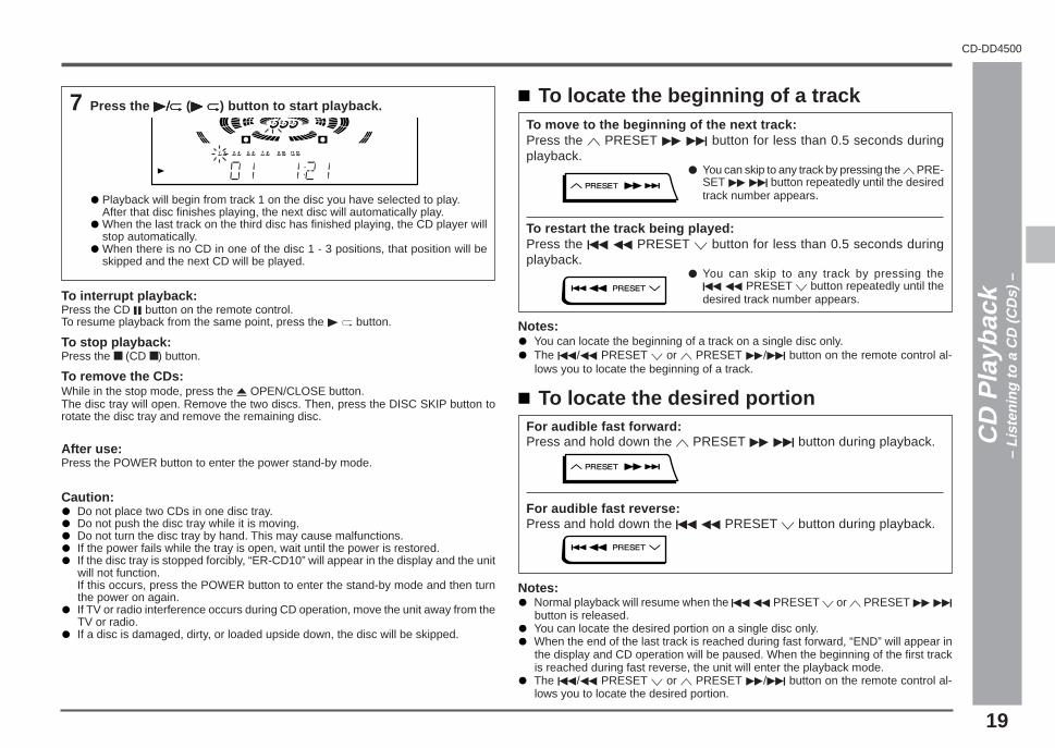
7 Press the 0/R 0/R 0/R 0/R 0/R (0 R0 R0 R0 R0 R) button to start playback.
Playback will begin from track 1 on the disc you have selected to play.After that disc finishes playing, the next disc will automatically play.When the last track on the third disc has finished playing, the CD player willstop automatically.When there is no CD in one of the disc 1 - 3 positions, that position will beskipped and the next CD will be played.
To interrupt playback:Press the CD 6 button on the remote control.To resume playback from the same point, press the 0 R button.
To stop playback:Press the ■ (CD ■) button.
To remove the CDs:While in the stop mode, press the 7 OPEN/CLOSE button.The disc tray will open. Remove the two discs. Then, press the DISC SKIP button torotate the disc tray and remove the remaining disc.
After use:Press the POWER button to enter the power stand-by mode.
Caution:Do not place two CDs in one disc tray.Do not push the disc tray while it is moving.Do not turn the disc tray by hand. This may cause malfunctions.If the power fails while the tray is open, wait until the power is restored.If the disc tray is stopped forcibly, “ER-CD10” will appear in the display and the unitwill not function.If this occurs, press the POWER button to enter the stand-by mode and then turnthe power on again.If TV or radio interference occurs during CD operation, move the unit away from theTV or radio.If a disc is damaged, dirty, or loaded upside down, the disc will be skipped.
To locate the desired portionFor audible fast forward:Press and hold down the W PRESET 2 4 button during playback.
For audible fast reverse:Press and hold down the 5 3 PRESET X button during playback.
Notes:Normal playback will resume when the 5 3 PRESET X or W PRESET 2 4
button is released.You can locate the desired portion on a single disc only.When the end of the last track is reached during fast forward, “END” will appear inthe display and CD operation will be paused. When the beginning of the first trackis reached during fast reverse, the unit will enter the playback mode.The 5/3 PRESET X or W PRESET 2/4 button on the remote control al-lows you to locate the desired portion.
To locate the beginning of a trackTo move to the beginning of the next track:Press the W PRESET 2 4 button for less than 0.5 seconds duringplayback.
● You can skip to any track by pressing the W PRE-SET 2 4 button repeatedly until the desiredtrack number appears.
To restart the track being played:Press the 5 3 PRESET X button for less than 0.5 seconds duringplayback.
● You can skip to any track by pressing the5 3 PRESET X button repeatedly until thedesired track number appears.
Notes:You can locate the beginning of a track on a single disc only.The 5/3 PRESET X or W PRESET 2/4 button on the remote control al-lows you to locate the beginning of a track.
Advanced CD playback (continued)
CD
Pla
ybac
k–
List
enin
g to
a C
D (
CD
s) –
20
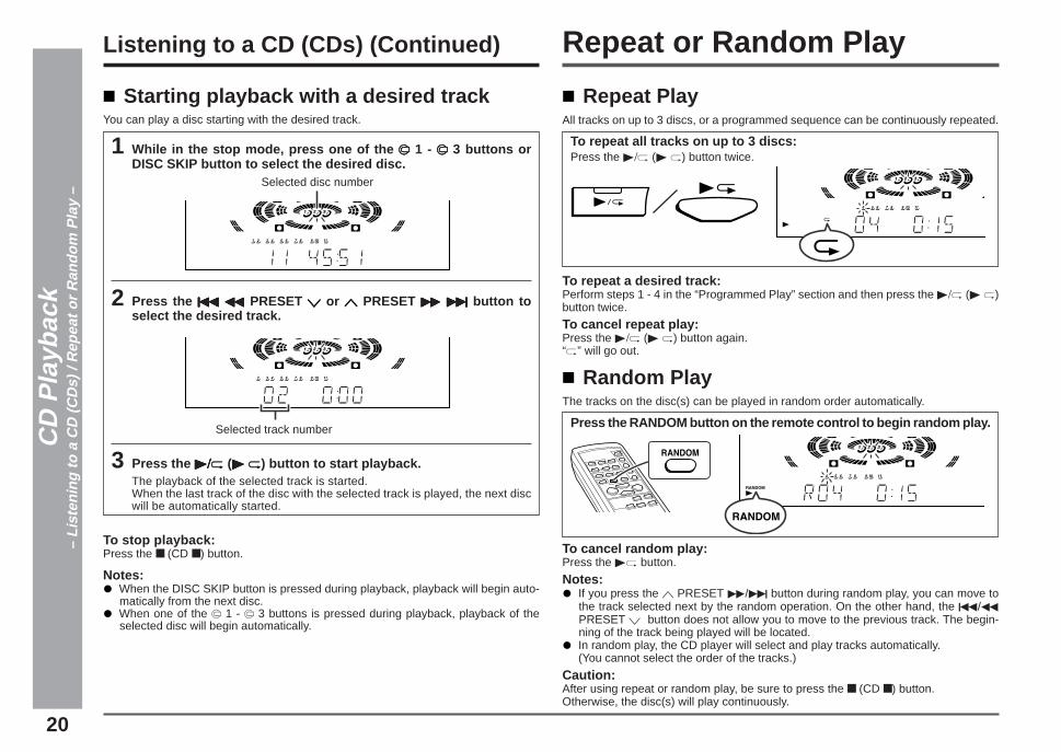
Repeat PlayAll tracks on up to 3 discs, or a programmed sequence can be continuously repeated.
To repeat all tracks on up to 3 discs:Press the 0/R (0 R) button twice.
To repeat a desired track:Perform steps 1 - 4 in the “Programmed Play” section and then press the 0/R (0 R)button twice.
To cancel repeat play:Press the 0/R (0 R) button again.“R” will go out.
Repeat or Random Play
Random PlayThe tracks on the disc(s) can be played in random order automatically.
Press the RANDOM button on the remote control to begin random play.
To cancel random play:Press the 0R button.
Notes:If you press the W PRESET 2/4 button during random play, you can move tothe track selected next by the random operation. On the other hand, the 5/3PRESET X button does not allow you to move to the previous track. The begin-ning of the track being played will be located.In random play, the CD player will select and play tracks automatically.(You cannot select the order of the tracks.)
Caution:After using repeat or random play, be sure to press the ■ (CD ■) button.Otherwise, the disc(s) will play continuously.
Starting playback with a desired trackYou can play a disc starting with the desired track.
1 While in the stop mode, press one of the s s s s s 1 - s s s s s 3 buttons orDISC SKIP button to select the desired disc.
2 Press the 5 3 5 3 5 3 5 3 5 3 PRESET X X X X X or W W W W W PRESET 2 4 2 4 2 4 2 4 2 4 button toselect the desired track.
3 Press the 0/R0/R0/R0/R0/R (0 R0 R0 R0 R0 R) button to start playback.The playback of the selected track is started.When the last track of the disc with the selected track is played, the next discwill be automatically started.
To stop playback:Press the ■ (CD ■) button.
Notes:When the DISC SKIP button is pressed during playback, playback will begin auto-matically from the next disc.When one of the s 1 - s 3 buttons is pressed during playback, playback of theselected disc will begin automatically.
Selected disc number
Selected track numberCD
Pla
ybac
k–
List
enin
g to
a C
D (
CD
s) /
Rep
eat o
r R
ando
m P
lay
–
Listening to a CD (CDs) (Continued)

21
CD-DD4500
1
2
3
4
5
6
7
8
9
10
11
12
13
14
15
Programmed Play
1 While in the stop mode,press one of the s s s s s 1 - s s s s s 3buttons to select the de-sired disc.
2 Press the 55555 3 3 3 3 3 PRESET XXXXXor W W W W W PRESET 2 4 2 4 2 4 2 4 2 4 buttonto select the desired track.
You can also select a track by pressing the 5/3 PRESET X or W PRE-SET 2/4 button on the remote control.
Selected disc number
Selected track number
3 Press the MEMORY/SET(MEMORY) button to save thetrack number.
When the track is memorized, “MEMORY” will appear.
4 Repeat steps 1 - 3 for other tracks. Up to 32 tracks can be pro-grammed.If you make a mistake, the programmed tracks can be cleared by pressing theCLEAR button.
5 Press the 0/R 0/R 0/R 0/R 0/R (0 R0 R0 R0 R0 R) button to start playback.
CD
Pla
ybac
k–
Pro
gram
med
Pla
y –
By specifying discs from 1 to 3, and tracks from 1 to 99, you can choose up to 32selections for playback in the order you like.
To clear the programmed selections:While in the stop mode, press the CLEAR button on theremote control.Each time the button is pressed, one track will be cleared,beginning with the last track programmed. When all thetracks are cleared, “MEMORY” will disappear.
Adding tracks to the program:If a program has been previously stored, the “MEMORY” indicator will be displayed.Then follow steps 1 - 3 to add tracks. The new tracks will be stored after the last track ofthe original program.
Notes:Opening the disc tray automatically cancels the programmed sequence.Even if you press the POWER button to enter the stand-by mode or change thefunction from CD to another, the programmed selections will not be cleared.During program operation, random play is not possible.
Playback order

22
To receive an FM stereo transmission:Press the TUNER (BAND) button so that the “ST” indicator lights up.
“j” will appear when an FM broadcast is in stereo.
If the FM reception is weak, press the TUNER (BAND) button so that the “ST” indi-cator goes out. The reception changes to monaural, and the sound becomes clearer.
After use:Press the POWER button to enter the power stand-by mode.
Listening to the Radio
1 Press the POWER button to turn the power on.
2 Press the TUNER (BAND) button repeatedly to select the desiredfrequency band (FM or AM).
3 Press the TUNING/TIME ( XXXXX or WWWWW) button to tune in to the desiredstation.
Manual tuning:Press the TUNING/TIME button as many times as required to tune in to thedesired station.
Auto tuning:When the TUNING/TIME button is pressed for more than 0.5 seconds, scan-ning will start automatically and the tuner will stop at the first receivable broad-cast station.
Notes:When radio interference occurs, auto scan tuning may stop automatically atthat point.Auto scan tuning will skip weak signal stations.To stop the auto tuning, press the TUNING/TIME button again.
FM stereo mode indicator
FM stereo receiving indicator
Rad
io–
List
enin
g to
the
Rad
io –
Sound Control (See page 16.)

23
CD-DD4500
1
2
3
4
5
6
7
8
9
10
11
12
13
14
15
To recall a memorized stationPress the 55555 33333 PRESET XXXXX or WWWWW PRESET 22222 44444 button for lessthan 0.5 seconds to select the desired station.
Memorizing a stationYou can store 40 AM and FM stations in memory and recall them at the push of abutton. (Preset tuning)
1 Perform the steps 1 - 3 in “Listening to the Radio” on page 22.
2 Press the MEMORY/SET button to enter the preset tuning savingmode.
3 Within 30 seconds, press the 55555 33333 PRESET XXXXX or WWWWW PRESET22222 44444 button to select the preset channel number.
Store the stations in memory, in order, starting with preset channel 1.
4 Within 30 seconds, press the MEMORY/SET button to store thatstation in memory.
If the “MEMORY” and preset number indicators go out before the station ismemorized, repeat the operation from step 2.
5 Repeat steps 1 - 4 to set other stations, or to change a presetstation.When a new station is stored in memory, the station previously memorized willbe erased.
Note:The backup function protects the memorized stations for a few hours should there bea power failure or the AC power cord disconnection.
Preset channel Frequency and frequency band
Rad
io–
List
enin
g to
the
Mem
oriz
ed S
tatio
n –
Listening to the Memorized Station
To erase entire preset memory1. Press the POWER button to enter the stand-by mode.2. Press the POWER button while holding down the TUNER (BAND) button and X-
BASS/DEMO button until “TUNER CL” appears.
Listening to the Radio (See page 22.)
To scan the preset stationsThe stations saved in memory can be scanned automatically. (Preset memory scan)
1 Press the 55555 33333 PRESET XXXXX or WWWWW PRESET 22222 44444 button formore than 0.5 seconds.The preset number will flash and the programmed stations will be tuned insequentially, for 5 seconds each.
2 Press the 55555 33333 PRESET XXXXX or WWWWW PRESET 22222 44444 button againwhen the desired station is located.
24
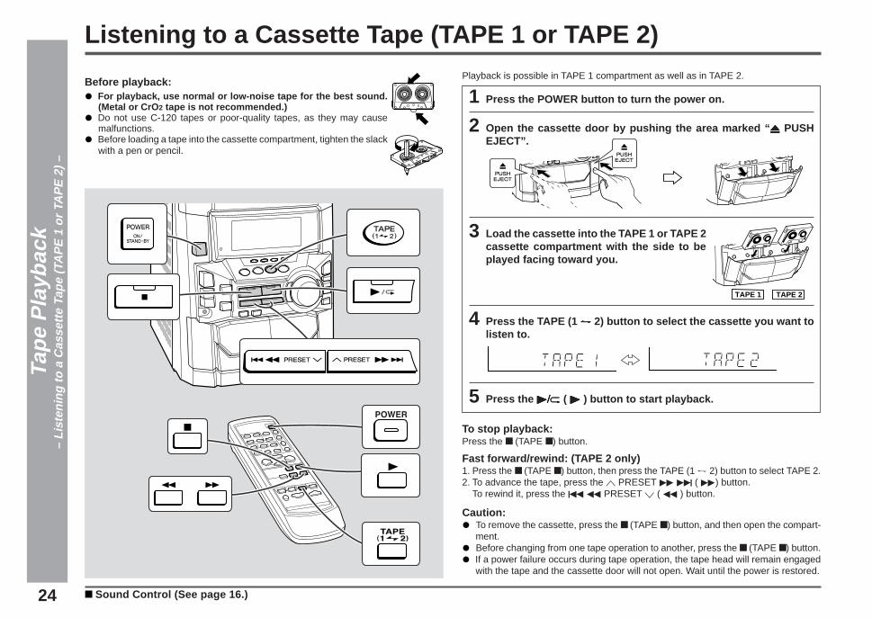
Listening to a Cassette Tape (TAPE 1 or TAPE 2)
1 Press the POWER button to turn the power on.
2 Open the cassette door by pushing the area marked “ 7 7 7 7 7 PUSHEJECT”.
3 Load the cassette into the TAPE 1 or TAPE 2cassette compartment with the side to beplayed facing toward you.
4 Press the TAPE (1 VVVVV 2) button to select the cassette you want tolisten to.
5 Press the 0/R0/R0/R0/R0/R ( 0 0 0 0 0 ) button to start playback.
To stop playback:Press the ■ (TAPE ■) button.
Fast forward/rewind: (TAPE 2 only)1. Press the ■ (TAPE ■) button, then press the TAPE (1 V 2) button to select TAPE 2.2. To advance the tape, press the W PRESET 2 4 ( 2) button.
To rewind it, press the 5 3 PRESET X ( 3 ) button.
Caution:To remove the cassette, press the ■ (TAPE ■) button, and then open the compart-ment.Before changing from one tape operation to another, press the ■ (TAPE ■) button.If a power failure occurs during tape operation, the tape head will remain engagedwith the tape and the cassette door will not open. Wait until the power is restored.
Before playback:For playback, use normal or low-noise tape for the best sound.(Metal or CrO 2 tape is not recommended.)Do not use C-120 tapes or poor-quality tapes, as they may causemalfunctions.Before loading a tape into the cassette compartment, tighten the slackwith a pen or pencil.
TAPE 1 TAPE 2
Tape
Pla
ybac
k–
List
enin
g to
a C
asse
tte T
ape
(TA
PE
1 o
r TA
PE
2)
–Playback is possible in TAPE 1 compartment as well as in TAPE 2.
Sound Control (See page 16.)

25
CD-DD4500
1
2
3
4
5
6
7
8
9
10
11
12
13
14
15
Tape
Rec
ordi
ng–
Rec
ordi
ng fr
om th
e R
adio
–
1 Tune in to the desired station (see page 22).
2 Load a cassette into the TAPE 2 cassette compartment with theside to be recorded on facing you.Wind past the leader of the tape, on which recording cannot be performed.
3 Press the REC PAUSE I6 I6 I6 I6 I6 (I6I6I6I6I6) button.
Recording will be paused.
4 Press the 0/R0/R0/R0/R0/R ( 0 0 0 0 0 ) button to start recording.
To interrupt recording:Press the REC PAUSE I6 (I6) button.To resume recording, press 0/R ( 0 ) button.
To stop recording:Press the ■ (TAPE ■) button.
Note:If you hear a whistling noise while recording an AM station, move the AM loop antenna.
Recording from the Radio
Erase-prevention tab of cassette tapes:● When recording on a cassette tape, make sure
that the erase-prevention tabs are not re-moved.Cassettes have removable tabs that preventaccidental recording or erasing.
● To protect the recorded sound, remove the tabafter recording.Cover the tab hole with adhesive tape to recordon the tape without the tab.
Side A
Tab for side ATab for side B
Recording can be operated in the TAPE 2 compartment. The TAPE 1 is for playbackonly.
Listening to the Radio (See page 22.)
Before recording:● When recording important selections, make a preliminary test to ensure that the
desired material is properly recorded.● SHARP is not liable for damage or loss of your recording arising from malfunction of
this unit.● The volume and sound controls can be adjusted with no effect on the recorded
signal (Variable Sound Monitor).● For recording, use only normal tapes. Do not use metal and CrO 2 tapes.
26
Tape
Rec
ordi
ng–
Rec
ordi
ng fr
om a
CD
(C
Ds)
–
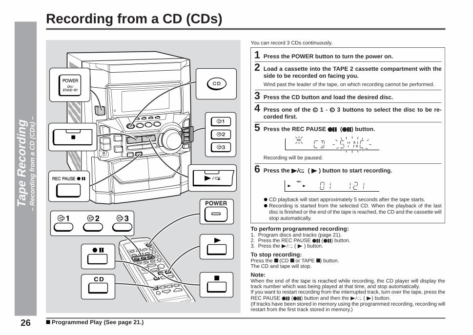
You can record 3 CDs continuously.
1 Press the POWER button to turn the power on.
2 Load a cassette into the TAPE 2 cassette compartment with theside to be recorded on facing you.Wind past the leader of the tape, on which recording cannot be performed.
3 Press the CD button and load the desired disc.
4 Press one of the s s s s s 1 - s s s s s 3 buttons to select the disc to be re-corded first.
5 Press the REC PAUSE I6I6I6I6I6 (I6I6I6I6I6) button.
Recording will be paused.
6 Press the 0/R0/R0/R0/R0/R ( 0 0 0 0 0 ) button to start recording.
CD playback will start approximately 5 seconds after the tape starts.Recording is started from the selected CD. When the playback of the lastdisc is finished or the end of the tape is reached, the CD and the cassette willstop automatically.
To perform programmed recording:1. Program discs and tracks (page 21).2. Press the REC PAUSE I6 (I6) button.3. Press the 0/R ( 0 ) button.
To stop recording:Press the ■ (CD ■ or TAPE ■) button.The CD and tape will stop.
Note:When the end of the tape is reached while recording, the CD player will display thetrack number which was being played at that time, and stop automatically.If you want to restart recording from the interrupted track, turn over the tape, press theREC PAUSE I6 (I6) button and then the 0/R ( 0) button.(If tracks have been stored in memory using the programmed recording, recording willrestart from the first track stored in memory.)
Recording from a CD (CDs)
Programmed Play (See page 21.)

27
CD-DD4500
1
2
3
4
5
6
7
8
9
10
11
12
13
14
15
You can record from TAPE 1 to TAPE 2.For recording, use only normal tapes. Do not use metal and CrO 2 tapes.
1 Press the POWER button to turn the power on.
2 Load a prerecorded cassette into the TAPE 1 cassette compart-ment. Insert a blank tape into the TAPE 2 cassette compartment.It is recommended that the recording tape be the same length as the mastertape.
3 Press the TAPE (1 VVVVV 2) button until “TAPE 1” appears in thedisplay.
4 Press the REC PAUSE I6 I6 I6 I6 I6 (I6I6I6I6I6) button.
Recording will be paused.
5 Press the 00000 / RRRRR ( 0 0 0 0 0 ) button to start dubbing.
To stop dubbing:Press the ■ (TAPE ■) button.TAPE 1 and TAPE 2 will simultaneously stop.
Erasing recorded tapes1. Load the tape to be erased into the TAPE 2 cassette compartment.2. Press the TAPE (1 V 2) button until “TAPE 2” appears in the display.3. Press the REC PAUSE I6 (I6) button. (“ERASE” will appears.)4. Press the 0 / R ( 0 ) button to start erasing.
Note:Make sure that the TAPE 1 is not in use.
Tape
Rec
ordi
ng–
Dub
bing
from
Tap
e to
Tap
e –
Dubbing from Tape to Tape
28
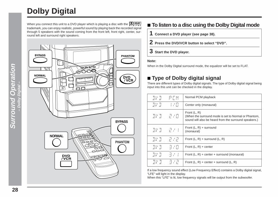
When you connect this unit to a DVD player which is playing a disc with the trademark, you can enjoy realistic, powerful sound by playing back the recorded signalthrough 5 speakers with the sound coming from the front left, front right, center, sur-round left and surround right speakers.
Dolby Digital
To listen to a disc using the Dolby Digital mode
1 Connect a DVD player (see page 38).
2 Press the DVD/VCR button to select “DVD”.
3 Start the DVD player.
Note:When in the Dolby Digital surround mode, the equalizer will be set to FLAT.
Type of Dolby digital signalThere are different types of Dolby digital signals. The type of Dolby digital signal beinginput into this unit can be checked in the display.
If a low frequency sound effect (Low Frequency Effect) contains a Dolby digital signal,“LFE” will light in the display.When this “LFE” is lit, low frequency signals will be output from the subwoofer.
Sur
roun
d O
pera
tion
– D
olby
Dig
ital –
Normal PCM playback
Center only (monaural)
Front (L, R)(When the surround mode is set to Normal or Phantom,sound will also be heard from the surround speakers.)
Front (L, R) + surround(monaural)
Front (L, R) + surround (L, R)
Front (L, R) + center
Front (L, R) + center + surround (monaural)
Front (L, R) + center + surround (L, R)

29
CD-DD4500
1
2
3
4
5
6
7
8
9
10
11
12
13
14
15
Enjoy the Surround Sound
Normal/Phantom/Bypass modeWhen you connect this unit to other equipment (DVD player, VCR, etc.) which is play-ing sound sources that have the or trademarks, you can enjoyDolby surround sound.
Normal mode:When you play a sound source that has the (5.1 channels) or trademarks, you can enjoy surround sound using all 5 speakers.
Sur
roun
d O
pera
tion
– E
njoy
the
Sur
roun
d S
ound
–
To listen to Normal/Phantom/Bypass mode:
1 Connect the unit you want to play (see page 38).
2 Press the DVD/VCR button to select the input (DVD or VCR) fromthe jack you connected in step 1.
3 Press the NORMAL, PHANTOM or BYPASS button to select the sur-round mode.NORMAL:
For a stereo 2 channel input or a Dolby digital 2/0 input, sound will be outputfrom the front left, front right, center and surround speakers. The same mon-aural channel will be output from the left and right surround speakers.For a Dolby digital 5.1 channel input, sound will be output from the front left,front right, center, surround left and surround right speakers.If the surround signal only contains 1 channel, the same monaural channelwill be output from the left and right surround speakers.For a Dolby digital 1/0 input, sound will only be output from the center speaker.
PHANTOM:The difference between this mode and the normal mode is that no sound isoutput from the center speaker.The center speaker signal is split equally and added to the sound for the frontleft and front right speakers.
BYPASS:Sound will only be output from the front left and front right speakers.For a Dolby digital multichannel input, any center or rear signals will be mixedand output from the front speakers.For a Dolby digital 1/0 input, monaural sound will be output from the frontspeakers.
4 Start playing the sound source.
Notes:If the EQUALIZER button is pressed in the Normal/Phantom/Virtual mode, the unitis switched to the Bypass mode automatically.When in the Normal/Phantom mode, the equalizer will be set to FLAT.You cannot use the Normal/Phantom and Dolby Digital surround features with headphones.When headphones are connected to the headphone jack, the Normal/Phantom andDolby Digital surround modes will be canceled. (The NORMAL or PHANTOM buttonwill not work.)When the headphones are disconnected, the Normal/Phantom mode will still becanceled. In order to activate the Normal/Phantom modes, you must press the NOR-MAL or PHANTOM button.Pressing the REC PAUSE I6 (I6) button cancels the Normal/Phantom/Virtual modeand the unit enters the Bypass mode.
Phantom mode:When you play a sound source that has the or trademarks,you can enjoy surround sound using 4 speakers, but not the center speaker.
Center speaker
Front speaker (Left) Front speaker (Right)
Surround (Left) Surround (Right)
Front speaker (Left) Front speaker (Right)
Surround (Left) Surround (Right)

30
Enjoy the Surround Sound (Continued)
Virtual Dolby SurroundThree-dimensional stereo image processing modifies the sound for the 2 front speak-ers to make it seem as if surround speakers were being sent signals, even though theyare not actually used.
You can enjoy a three-dimensional surround stereo image using just the 2 front speak-ers.
Sur
roun
d O
pera
tion
– E
njoy
the
Sur
roun
d S
ound
–
: Indicates a virtual speaker.
Front speaker (Right)Front speaker (Left)
Virtual Dolby Surround
To listen to Virtual Dolby Surround sound:
1 Select the desired audio source and begin playback.
2 Press the VIRTUAL button to select “VIRTUAL”.When a Dolby digital signal is being input, “ VIRTUAL” and “ DIGITAL”will appear.

31
CD-DD4500
1
2
3
4
5
6
7
8
9
10
11
12
13
14
15
Speaker size setting
1 Press the MENU button repeatedly to select “SP SIZE”.
2 Within 8 seconds, press the ITEM button to select “FRONT”.
The front speaker indicators will light up.
3 Within 8 seconds, use the SET UP ( WWWWW or XXXXX) button on the re-mote control to select “LARGE” or “SMALL”.
LARGE: When the front speakers can reproduce low frequencies (speakerswhich can reproduce sounds lower than 60 Hz)
SMALL: When the front speakers cannot reproduce extremely low frequencies
Changing the Speaker SettingYou can change the setting as you like.The initial set up was made when shipped from the factory.The unit can be used as it is, straight out of the box.
4 Repeat the operation in steps 2 and 3 above to select “SUR-ROUND”, “CENTER” and “S-WOOFER”.
Each of these items can be set separately.
Surround speakers:
Center speaker:
Subwoofer:
YES: When the speakers are connectedNO: When no speaker is connected (When NO is selected, the indica-
tor for that speaker position will go out.)
INT: Setting of the internal subwooferEXT: Setting of the external subwoofer (see page 39.)
Note:When all 5 speakers have been connected, set each of the items to “YES” and thesubwoofer to “SW-INT”.The sound is output from the subwoofer when in the Bypass/Virtual mode, even ifthe setting of subwoofer is changed.
Sur
roun
d O
pera
tion
– C
hang
ing
the
Spe
aker
Set
ting
–
disappear
disappear
disappear
disappear

32
Changing the Speaker Setting (Continued)
Speaker delay settingThe best sound will be achieved by placing the front speakers, center speaker andsurround speakers at the same distance from the listener.When some of the speakers are at a different distance from the listener, you can selecta speaker delay to make it seem as though the speaker distances are the same.(Factory-shipped settings: CENTER → 0 ms, SURROUND → 5 ms)If the settings need to be changed due to the type of sound source being played or theconditions in the room, change them as follows.
Sur
roun
d O
pera
tion
– C
hang
ing
the
Spe
aker
Set
ting
–
1 Press the MENU button repeatedly to select “SP DELAY”.
2 Within 8 seconds, press the ITEM button to select “CENT” or“SURR”.
CENT: To delay the sound from the center speakerSURR: To delay the sound from the surround speakers
3 Within 8 seconds, use the SET UP ( WWWWW or XXXXX) button on the re-mote control to select a value.Adjustable rangeCENTER: 0 ms - 5 msSURROUND: 0 ms - 15 ms(Can be changed in 1 ms steps.)
Notes:As a guide for setting the correct delay time, 1 ms is equal to approximately 12" (30cm) from where the selected speakers are placed further away from the listenerthan the typical location.If the delay time for the surround speakers is set to a large value, a large soundspace will be created. If it is set to a small value, the sound space will be small andintimate.

33
CD-DD4500
1
2
3
4
5
6
7
8
9
10
11
12
13
14
15
Speaker level settingThe output level of each speaker can be adjusted.
1 Press the MENU button repeatedly to select “SP LEVEL”.
2 Within 8 seconds, press the ITEM button repeatedly to select thespeaker (CENT, RSUR, LSUR or SWFR) you want to adjust.
3 Within 8 seconds, use the SET UP ( WWWWW or XXXXX) button on the re-mote control to adjust the level.You can change the level within a range of +10dB to –10dB, in 1dB steps.
Set Up (Continued)
Sur
roun
d O
pera
tion
– C
hang
ing
the
Spe
aker
Set
ting
–
Front speaker balance settingYou can adjust the balance between the left and right channels of the front speakers.
1 Press the MENU button repeatedly to select “SP LEVEL”.
2 Within 8 seconds, press the ITEM button.
3 Within 8 seconds, press the SET UP WWWWW button to increase theright speaker level (the left speaker level to decrease), or pressthe SET UP XXXXX button to increase the left speaker level (the rightspeaker level will decrease).
The speaker balance, as shown in the display, can be changed within the rangeof “1” to “10”.
Note:The surround speaker balance will not be changed.
To make the balance flat:In step 3, use the SET UP (W or X) button on the remote control to select “F-SP CEN”.

34
Changing the Speaker Setting (Continued)
Dynamic range settingDVD discs have a wider dynamic range (sound volume range) than existing VHS vid-eotapes or CD discs. If they are played in home systems, there may be too muchdifference between the loud and quiet sounds. Therefore, if the volume is set so thatthe quiet sounds can be heard clearly, the loud sounds may be far too loud.On the other hand, if the volume is set so that the loud sounds are not too loud, youmay not be able to hear the quiet sounds. Three settings are available to control thedynamic range easily.
1 Press the MENU button repeatedly to select “D-RANGE”.
2 Within 8 seconds, press the ITEM button.
3 Within 8 seconds, press the SET UP ( WWWWW or XXXXX) button to select“MAX”, “STD” or “MIN”.
MAX: This setting does not compress the dynamic range of the Dolby digitalsignal, allowing you to enjoy the full, powerful sound of Dolby encodeddigital signals.
STD: This setting compresses the dynamic range, and may produce a moreappropriate volume range for home use.
MIN: This setting compresses the dynamic range, allowing you to enjoy mov-ies at a lower volume.
Sur
roun
d O
pera
tion
– C
hang
ing
the
Spe
aker
Set
ting
–
Test toneYou can check (and adjust) the speaker level by listening to the sound output fromeach speaker individually, while standing at the actual listening position in the room.The speaker level can be adjusted using the remote control.
1 Press the MENU button repeatedly to select “TEST”.
2 Within 8 seconds, press the ITEM button.The test tone will be heard from each speaker, in order, at about 5 secondintervals.
CENTER → FRONT RIGHT↑ ↓
FRONT LEFT R-SURROUND↑ ↓
S-WOOFER ← L-SURROUND
When the test tone is being output, the indicator for that speaker will flash.The test tone will be heard until the current menu selection is changed bypressing the MENU button again, or by selecting some other function.
3 To adjust the speaker level while the test tone is being outputfrom a particular speaker, press the SET UP ( WWWWW or XXXXX) button.
The speaker level can be adjusted within a range of +10dB to –10dB, in 1dBsteps.
Notes:If “NO” is selected for any individual speaker’s size setting (page 31), the test tonewill not be heard from that speaker.Note that the front left and front right speaker levels cannot be adjusted using thismethod.If the subwoofer, equipped with a front speaker, is set to “EXT” in the speaker sizesetting procedure, no sound is emitted from it.

35
CD-DD4500
1
2
3
4
5
6
7
8
9
10
11
12
13
14
15
Description of Terminology
Sur
roun
d O
pera
tion
– D
escr
iptio
n of
Ter
min
olog
y –
Dolby Pro Logic Surround:This refers to the Dolby Surround sound decoder system which is used for movies.Using 4 channels, the sound effects, dialog, sound direction, music, etc. are all repro-duced more realistically. Dolby Pro Logic Surround makes the location and movementof sounds much more natural than the original Dolby Surround system. You can enjoya realistic, powerful feeling like being at a live performance or as if you were at a movietheater or in a concert hall. In order to enjoy this effect, you need at least one pair ofsurround speakers.
Dolby Digital:This is the new digital surround system that was created to reproduce theater qualitystereophonic Dolby Surround sound at home. Films are now recorded using the 5.1channel system. Dolby Digital can handle the original soundtrack without modification,allowing you to enjoy the sound field created by the film maker at home.
Dolby Surround:This is the encoding/decoding system for general-purpose Dolby Surround. When thesound from films recorded in Dolby Surround are reproduced, you will have the feelingof being at a live performance, as if the action is taking place right in front of you.
LFE (Low Frequency Effect):This refers to the special low-frequency sound effects used in Dolby Digital recordings.When a signal containing LFE encoding is played by this unit, “LFE” will appear in thedisplay.
PCM (Pulse Code Modulation)This is a recording/transmission system used for digital audio signals. This unit canhandle sampling frequencies of 32 kHz, 44.1 kHz and 48 kHz.
Subwoofer:The subwoofer is a special speaker used to emphasize bass sounds.In Dolby Digital, this speaker reproduces the LFE signals as well as the low-frequencysignals being sent to the front, center and surround speakers.In Dolby Pro Logic, this speaker reproduces the low-frequency signals sent to the frontand center speakers.It also reproduces low frequency sounds from ordinary stereo recordings.
Dolby Pro Logic Dolby Digital
2
4
Front (L, R) + Center + Rear
Matrix processing, DolbySurround
16 bits
7 kHz
6
6
Front (L, R) + Center + Rear(L, R) + Low frequency
effects
Discrete processing, Dolbydigital encoding/decoding
20 bits
20 kHz
Number of recordingchannels
Number of playbackchannels
Playback configurationof channels
Sound processing
Number of signalprocessing bits
Surround Sound high-frequency playback
limit
S
S
LS
C
RS
L RCL R
36
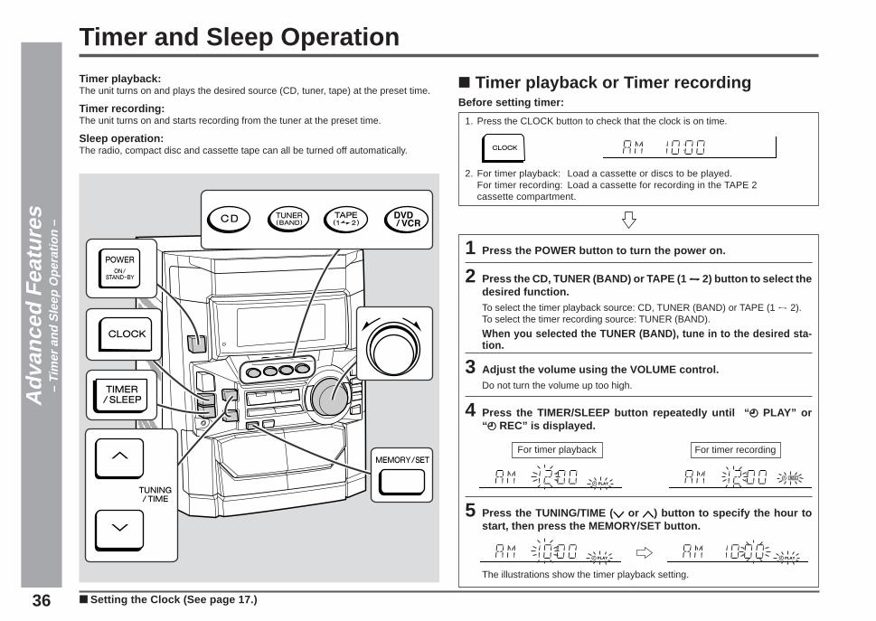
1 Press the POWER button to turn the power on.
2 Press the CD, TUNER (BAND) or TAPE (1 VVVVV 2) button to select thedesired function.To select the timer playback source: CD, TUNER (BAND) or TAPE (1 V 2).To select the timer recording source: TUNER (BAND).
When you selected the TUNER (BAND), tune in to the desired sta-tion.
3 Adjust the volume using the VOLUME control.Do not turn the volume up too high.
4 Press the TIMER/SLEEP button repeatedly until “ f f f f f PLAY” or“ f f f f f REC” is displayed.
5 Press the TUNING/TIME ( X X X X X or WWWWW) button to specify the hour tostart, then press the MEMORY/SET button.
The illustrations show the timer playback setting.
■ Timer playback or Timer recordingBefore setting timer:
1. Press the CLOCK button to check that the clock is on time.
2. For timer playback: Load a cassette or discs to be played.For timer recording: Load a cassette for recording in the TAPE 2cassette compartment.
Timer and Sleep OperationTimer playback:The unit turns on and plays the desired source (CD, tuner, tape) at the preset time.
Timer recording:The unit turns on and starts recording from the tuner at the preset time.
Sleep operation:The radio, compact disc and cassette tape can all be turned off automatically.
Adv
ance
d F
eatu
res
– Ti
mer
and
Sle
ep O
pera
tion
–
■ Setting the Clock (See page 17.)
For timer playback For timer recording
*CD_DD4500_P36_39 2001.4.19, 11:43 PM36
37
CD-DD4500
1
2
3
4
5
6
7
8
9
10
11
12
13
14
15
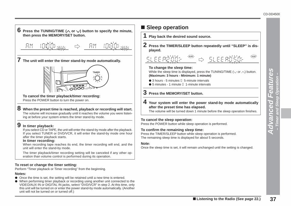
6 Press the TUNING/TIME ( W W W W W or XXXXX) button to specify the minute,then press the MEMORY/SET button.
7 The unit will enter the timer stand-by mode automatically.
To cancel the timer playback/timer recording:Press the POWER button to turn the power on.
8 When the preset time is reached, playback or recording will start.The volume will increase gradually until it reaches the volume you were listen-ing at before your system enters the timer stand-by mode.
9 In timer playback:If you select CD or TAPE, the unit will enter the stand-by mode after the playback.If you select TUNER or DVD/VCR, it will enter the stand-by mode one hourafter the timer playback starts.In timer recording:When recording tape reaches its end, the timer recording will end, and theunit will enter the stand-by mode.
The timer playback/timer recording setting will be canceled if any other op-eration than volume control is performed during its operation.
To reset or change the timer setting:Perform “Timer playback or Timer recording” from the beginning.
Notes:● Once the time is set, the setting will be retained until a new time is entered.● When performing timer playback or recording using another unit connected to the
VIDEO/AUX IN or DIGITAL IN jacks, select “DVD/VCR” in step 2. At this time, onlythis unit will be turned on or enter the power stand-by mode automatically. (Anotherunit will not be turned on or turned off.)
Timer and Sleep Operation (continued)
■ Sleep operation
1 Play back the desired sound source.
2 Press the TIMER/SLEEP button repeatedly until “SLEEP” is dis-played.
To change the sleep time:While the sleep time is displayed, press the TUNING/TIME (X or W) button.(Maximum: 3 hours - Minimum: 1 minute)
● 3 hours - 5 minutes → 5-minute intervals● 5 minutes - 1 minute → 1-minute intervals
3 Press the MEMORY/SET button.
4 Your system will enter the power stand-by mode automaticallyafter the preset time has elapsed.The volume will be turned down 1 minute before the sleep operation finishes.
To cancel the sleep operation:Press the POWER button while sleep operation is performed.
To confirm the remaining sleep time:Press the TIMER/SLEEP button while sleep operation is performed.The remaining sleep time is displayed for about 5 seconds.
Note :Once the sleep time is set, it will remain unchanged until the setting is changed.
Adv
ance
d F
eatu
res
– Ti
mer
and
Sle
ep O
pera
tion
–
■ Listening to the Radio (See page 22.)
*CD_DD4500_P36_39 2001.4.19, 11:43 PM37

38
Adv
ance
d F
eatu
res
– E
nhan
cing
You
r S
yste
m –
Cords required to connect an external unitWhen external units are connected, commercially available cords are needed.
Enhancing Your System
To the digitaloutput jack
Optical digital cord(not supplied)
To the line output jack
VCR etc.
DVD player
RCA cord(not supplied)
Speaker with abuilt-in amplifier
TV
*CD_DD4500_P36_39 2001.4.19, 11:43 PM38

39
CD-DD4500
1
2
3
4
5
6
7
8
9
10
11
12
13
14
15
Enhancing Your System (Continued)
To record on a tape from DVD or VCR etc.
1 Load a cassette in the TAPE 2 cassette compartment.
2 Press the DVD/VCR button.
To select the unit connected to the DVD jackPress the DVD/VCR button repeatedly to select “DVD”.To select the unit connected to the VIDEO/AUX IN jackPress the DVD/VCR button repeatedly to select “VCR”.
3 Press the REC PAUSE I6 I6 I6 I6 I6 (I6I6I6I6I6) button.
4 Press the 0/R 0/R 0/R 0/R 0/R ( 0 0 0 0 0 ) button.
5 Play the DVD, VCR etc.
Note:A DVD player allows you to select the “PCM” or “DOLBY DIGITAL” audio output mode.Before playing a Dolby digital sound disc, be sure to set the unit in the “DOLBY DIGI-TAL” mode. For more details, see the operation manual for your DVD player.
HeadphonesBefore plugging in or unplugging the headphones, reduce the volume.Be sure your headphones have a 1/8" (3.5 mm) diameter plug and are between 16ohms and 50 ohms impedance. The recommended impedance is 32 ohms.Plugging in the headphones disconnects the speakers automatically. Adjust thevolume using the VOLUME control.
Note:It is not possible to use the Normal/Phantom or Dolby Digital surround modes whenusing your headphones.When headphones are connected to the headphones jack, the Normal/Phantom modewill be canceled. (The unit will be set to the Bypass mode automatically.)
Adv
ance
d F
eatu
res
– E
nhan
cing
You
r S
yste
m –
Using subwoofer speakers of other equipmentWhen a commercially available speaker with a built-in amplifier is connected to thisunit, you can enjoy sound with emphasized bass.
1 Connect an RCA cord from a commercially available speaker witha built-in amplifier to the SUBWOOFER OUT jack.
2 Set the unit to “SW-EXT” in “Speaker size setting” (see page 31).
Note:No sound is heard from the external subwoofer when in the Bypass/Virtual mode.
*CD_DD4500_P36_39 2001.4.19, 11:43 PM39
40
Ref
eren
ces
– Tr
oubl
esho
otin
g C
hart
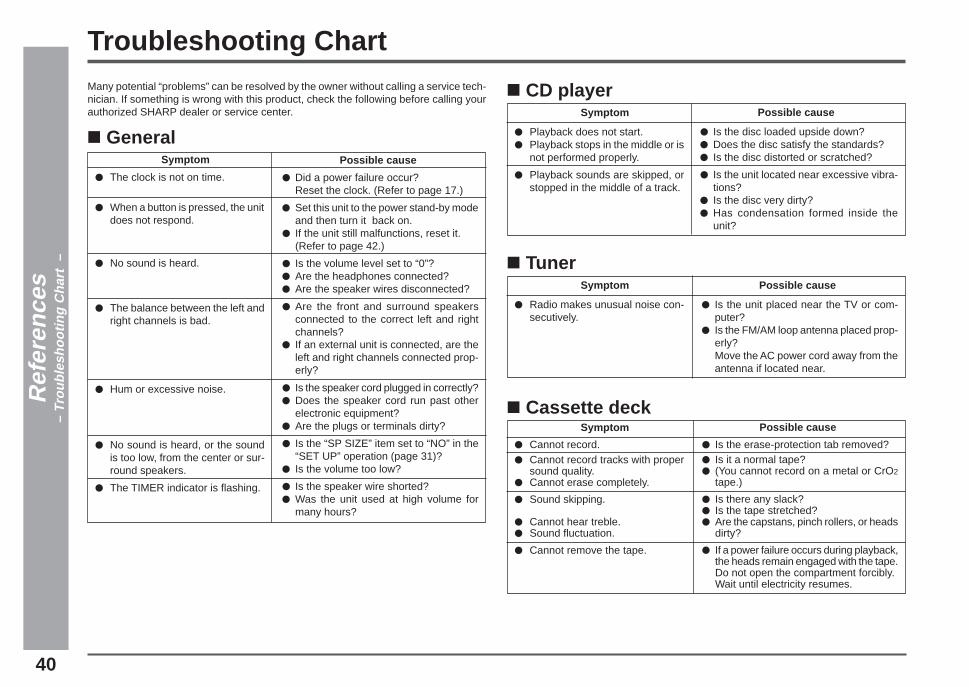
–Troubleshooting ChartMany potential “problems” can be resolved by the owner without calling a service tech-nician. If something is wrong with this product, check the following before calling yourauthorized SHARP dealer or service center.
■ TunerSymptom
● Radio makes unusual noise con-secutively.
Possible cause
● Is the unit placed near the TV or com-puter?
● Is the FM/AM loop antenna placed prop-erly?Move the AC power cord away from theantenna if located near.
■ GeneralSymptom
● The clock is not on time.
● When a button is pressed, the unitdoes not respond.
● No sound is heard.
● The balance between the left andright channels is bad.
● Hum or excessive noise.
● No sound is heard, or the soundis too low, from the center or sur-round speakers.
● The TIMER indicator is flashing.
■ CD playerSymptom
● Playback does not start.● Playback stops in the middle or is
not performed properly.
● Playback sounds are skipped, orstopped in the middle of a track.
Possible cause
● Is the disc loaded upside down?● Does the disc satisfy the standards?● Is the disc distorted or scratched?
● Is the unit located near excessive vibra-tions?
● Is the disc very dirty?● Has condensation formed inside the
unit?
Possible cause
● Did a power failure occur?Reset the clock. (Refer to page 17.)
● Set this unit to the power stand-by modeand then turn it back on.
● If the unit still malfunctions, reset it.(Refer to page 42.)
● Is the volume level set to “0”?● Are the headphones connected?● Are the speaker wires disconnected?
● Are the front and surround speakersconnected to the correct left and rightchannels?
● If an external unit is connected, are theleft and right channels connected prop-erly?
● Is the speaker cord plugged in correctly?● Does the speaker cord run past other
electronic equipment?● Are the plugs or terminals dirty?
● Is the “SP SIZE” item set to “NO” in the“SET UP” operation (page 31)?
● Is the volume too low?
● Is the speaker wire shorted?● Was the unit used at high volume for
many hours?
■ Cassette deckSymptom
● Cannot record.● Cannot record tracks with proper
sound quality.● Cannot erase completely.
● Sound skipping.
● Cannot hear treble.● Sound fluctuation.
● Cannot remove the tape.
Possible cause
● Is the erase-protection tab removed?● Is it a normal tape?● (You cannot record on a metal or CrO2
tape.)
● Is there any slack?● Is the tape stretched?● Are the capstans, pinch rollers, or heads
dirty?
● If a power failure occurs during playback,the heads remain engaged with the tape.Do not open the compartment forcibly.Wait until electricity resumes.
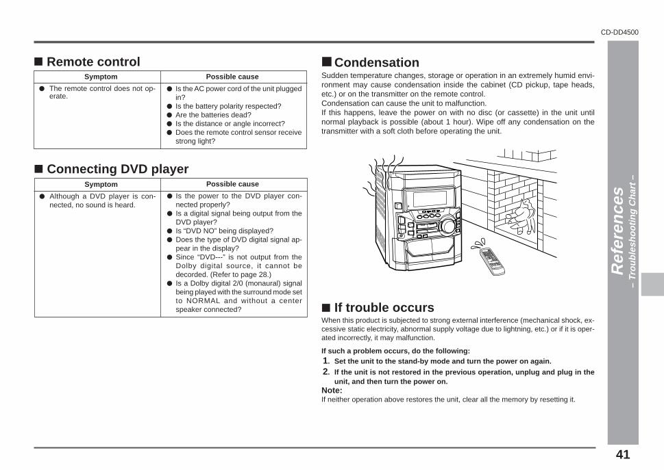
41
CD-DD4500
1
2
3
4
5
6
7
8
9
10
11
12
13
14
15
Troubleshooting Chart (continued)
Ref
eren
ces
– Tr
oubl
esho
otin
g C
hart
–
■ Remote controlSymptom
● The remote control does not op-erate.
Possible cause
● Is the AC power cord of the unit pluggedin?
● Is the battery polarity respected?● Are the batteries dead?● Is the distance or angle incorrect?● Does the remote control sensor receive
strong light?
■ CondensationSudden temperature changes, storage or operation in an extremely humid envi-ronment may cause condensation inside the cabinet (CD pickup, tape heads,etc.) or on the transmitter on the remote control.Condensation can cause the unit to malfunction.If this happens, leave the power on with no disc (or cassette) in the unit untilnormal playback is possible (about 1 hour). Wipe off any condensation on thetransmitter with a soft cloth before operating the unit.
■ Connecting DVD playerSymptom
● Although a DVD player is con-nected, no sound is heard.
Possible cause
● Is the power to the DVD player con-nected properly?
● Is a digital signal being output from theDVD player?
● Is “DVD NO” being displayed?● Does the type of DVD digital signal ap-
pear in the display?● Since “DVD---” is not output from the
Dolby digital source, it cannot bedecorded. (Refer to page 28.)
● Is a Dolby digital 2/0 (monaural) signalbeing played with the surround mode setto NORMAL and without a centerspeaker connected? ■ If trouble occurs
When this product is subjected to strong external interference (mechanical shock, ex-cessive static electricity, abnormal supply voltage due to lightning, etc.) or if it is oper-ated incorrectly, it may malfunction.
If such a problem occurs, do the following:1. Set the unit to the stand-by mode and turn the power on again.
2. If the unit is not restored in the previous operation, unplug and plug in theunit, and then turn the power on.
Note:If neither operation above restores the unit, clear all the memory by resetting it.

42
When TIMER indicator is flashingThe unit will be overheated when TIMER indicator is flashing.Due to a problem in the speaker circuit, the unit will enter the stand-by modeautomatically.In this case, take the following corrective actions.1. Unplug the AC power plug from the AC outlet.
2. Make sure that the unit vent is not blocked.
3. Make sure that the speaker wires have been correctly connected to thespeaker terminals.
4. After checking items 2 and 3 above, wait for 2 or 3 hours before trying to usethe unit.
5. Reconnect the AC power cord.
Note:If the TIMER indicator flashes again during use, please unplug the AC power plug,and contact a SHARP authorized service center.
Ref
eren
ces
– Tr
oubl
esho
otin
g C
hart
–Troubleshooting Chart (continued)
■ Before transporting the unit1. Press the POWER button to turn the power on.2. Press the CD button.3. Press the 77777 OPEN/CLOSE button to open the disc tray.
Remove all CDs inserted the unit.4. Press the 77777 OPEN/CLOSE button to close the disc tray.
Make sure that “NO DISC” is displayed.5. Press the POWER button to enter the stand-by mode, and then unplug the
AC power cord from the AC outlet.
■ Clearing all the memory (reset)1. Press the POWER button to enter the power stand-by mode.
2. While pressing down the 00000 / RRRRR button and X-BASS/DEMO button, pressthe POWER button until “CLEAR AL” appears.
Caution:This operation will erase all data stored in memory including clock, timer settings,tuner preset, CD program, and other set-up details.

43
CD-DD4500
1
2
3
4
5
6
7
8
9
10
11
12
13
14
15
Cleaning the tape-handling partsDirty heads, capstans or pinch rollers can cause poor sound and tape jams. Cleanthese parts with a cotton swab moistened with commercial head/pinch roller cleaneror isopropyl alcohol.When cleaning the heads, pinch rollers, etc., unplug the unit which contains highvoltages.
A Playback head D Erase headB Capstan E Recording/Playback head
C Pinch roller
After long use, the deck’s heads and capstans may become magnetized, causingpoor sound. Demagnetize these parts once every 30 hours of playing/recordingtime by using a commercial tape head demagnetizer. Read the demagnetizer’sinstructions carefully before use.In order to ensure proper operation of the CD player, preventative maintenance(cleaning of the laser pickup lens) should be performed periodically.Lens cleaners are commercially available. Contact your local CD software dealerfor options.
Cleaning the cabinetPeriodically wipe the cabinet with a soft cloth and a diluted soap solution, then with adry cloth.
Caution:Do not use oil, solvents, gasoline, paint thinners or insecticides on the unit.
Maintenance
TAPE 1
TAPE 2
A C
CD E
B
B

44
Ref
eren
ces
– S
peci
ficat
ions
–
CD playerType 3-disc multi-play compact disc player
Signal readout Non-contact, 3-beam semiconductor laser pickup
D/A converter 1-bit D/A converter
Frequency response 20 - 20,000 Hz
Dynamic range 100 dB (1 kHz)
TunerFrequency range FM: 87.5-108 MHz
AM: 530-1,720 kHz
Cassette deck Frequency response 50 -14,000 Hz (Normal tape)
Signal/noise ratio 55 dB (TAPE 1, playback)50 dB (TAPE 2, recording/playback)
Wow and flutter 0.25 % (WRMS)
Specifications
GeneralPower source AC 120 V, 60 Hz
Power consumption 230 W
Dimensions Width: 10-11/16" (270 mm)Height: 13" (330 mm)Depth: 14-11/16" (372 mm)
Weight 19.4 lbs (8.8 kg)
AmplifierOutput power Front speakers (Main) : 30 W minimum RMS per chan-
nel into 8 ohms.Front speakers (Subwoofer) : 40 W per channel : 6 ohms(100 Hz, 10 % T.H.D.)Center speaker : 30W : 6 ohms(1 kHz, 10 % T.H.D.)Surround speakers : 20W per channel : 8 ohms(1 kHz, 10 % T.H.D.)
Output terminals Front speakers (Main) : 8 ohmsFront speakers (Subwoofer) : 6 ohmsCenter speaker : 6 ohmsSurround speakers : 8 ohmsSubwoofer(Pre-out) : 10 kohmsHeadphones : 16-50 ohms (recommended; 32 ohms)
Input terminals DVD (Digital) : OpticalVCR/Auxiliary : 500 mV/47 kohms
As part of our policy of continuous improvement, SHARP reserves the right to makedesign and specification changes for product improvement without prior notice. Theperformance specification figures indicated are nominal values of production units.There may be some deviations from these values in individual units.

45
CD-DD4500
1
2
3
4
5
6
7
8
9
10
11
12
13
14
15
Front speaker with subwooferType 3 - way, 5-1/8" (130 mm) subwoofer, 4" (100 mm)
woofer and 2" (50 mm) tweeter
Maximum input power Subwoofer: 80 WMain: 60 W
Impedance Subwoofer: 6 ohms/ Main: 8 ohms
Dimensions Width: 8- 5/8" (220 mm)Height: 13" (330 mm)Depth: 9- 5/8" (245 mm)
Weight 9.0 lbs. (4.1 kg)/each
Center speakerType Full range, 4" (100 mm)
Maximum input power 60 W
Impedance 6 ohms
Dimensions Width: 10- 1/4" (260 mm)Height: 5- 5/8" (142 mm)Depth: 6- 11/16" (170 mm)
Weight 2.2 lbs. (1.0 kg)/each
Surround speakerType Full range, 4" (100 mm)
Maximum input power 40 W
Impedance 8 ohms
Dimensions Width: 7- 7/8" (200 mm)Height: 6- 3/4" (172 mm)Depth: 3- 3/4" (95 mm)
Weight 1.3 lbs. (0.6 kg)/each
Specifications (continued)
Ref
eren
ces
– S
peci
ficat
ions
–

MEMO

MEMO
Printed in MalaysiaA0104.YT
CD-DD4500 Mini Component System
TINSE0378AWZZ
SHARP ELECTRONICS CORPORATIONSharp Plaza, Mahwah, New Jersey 07430-2135
SHARP CORPORATION 9906
CONSUMER LIMITED WARRANTYSHARP ELECTRONICS CORPORATION warrants to the first consumer purchaser that this Sharp brand product (the “Product”), when shipped in its original con-tainer, will be free from defective workmanship and materials, and agrees that it will, at its option, either repair the defect or replace the defective Product or part thereofwith a new or remanufactured equivalent at no charge to the purchaser for parts or labor for the period(s) set forth below.
This warranty does not apply to any appearance items of the Product nor to the additional excluded item(s) set forth below nor to any Product the exterior of which hasbeen damaged or defaced, which has been subjected to improper voltage or other misuse, abnormal service or handling, or which has been altered or modified indesign or construction.
In order to enforce the rights under this limited warranty, the purchaser should follow the steps set forth below and provide proof of purchase to the servicer.
The limited warranty described herein is in addition to whatever implied warranties may be granted to purchasers by law. ALL IMPLIED WARRANTIES INCLUDINGTHE WARRANTIES OF MERCHANTABILITY AND FITNESS FOR USE ARE LIMITED TO THE PERIOD(S) FROM THE DATE OF PURCHASE SET FORTH BELOW.Some states do not allow limitations on how long an implied warranty lasts, so the above limitation may not apply to you.
Neither the sales personnel of the seller nor any other person is authorized to make any warranties other than those described herein, or to extend the duration of anywarranties beyond the time period described herein on behalf of Sharp.
The warranties described herein shall be the sole and exclusive warranties granted by Sharp and shall be the sole and exclusive remedy available to the purchaser.Correction of defects, in the manner and for the period of time described herein, shall constitute complete fulfillment of all liabilities and responsibilities of Sharp to thepurchaser with respect to the Product, and shall constitute full satisfaction of all claims, whether based on contract, negligence, strict liability or otherwise. In no eventshall Sharp be liable, or in any way responsible, for any damages or defects in the Product which were caused by repairs or attempted repairs performed by anyoneother than an authorized servicer. Nor shall Sharp be liable or in any way responsible for any incidental or consequential economic or property damage. Some statesdo not allow the exclusion of incidental or consequential damages, so the above exclusion may not apply to you.
THIS WARRANTY GIVES YOU SPECIFIC LEGAL RIGHTS. YOU MAY ALSO HAVE OTHER RIGHTS WHICH VARY FROM STATE TO STATE.
Model Specific SectionYour Product Model Number & Description:
(Be sure to have this information available when you need service for your Product.)Warranty Period for this Product: One (1) year parts and labor from the date of purchase.Additional Item(s) Excluded from W arranty Coverage (if any): Non-functional accessories, supplies, and consumable items.Where to Obtain Service: At a Sharp Authorized Servicer located in the United States.
To find a location of the nearest Sharp Authorized Servicer, call Sharp toll free at 1-800-BE-SHARP.What to do to Obtain Service: Ship prepaid or carry in your Product to a Sharp Authorized Servicer.
Be sure to have Proof of Purchase available. If you ship the Product, be sure it is insured andpackaged securely.
TO OBTAIN SUPPLY, ACCESSORY OR PRODUCT INFORMATION, CALL 1-800-BE-SHARP .0005