aep.com€¦ · FGD LANDFILL-CCR REVISED GROUNDWATER MONITORING WELL NETWORK EVALUATION arcadis.com ...

RUN‐ON AND RUN‐OFF CONTROL PLAN
PLANT GORGAS CCR LANDFILL
ALABAMA POWER COMPANY
Section 257.81 of EPA’s regulations requires the owner or operator of an existing or new CCR landfill or
any lateral expansion of a CCR landfill to prepare a run‐on and run‐off control system plan to document
how these control systems have been designed and constructed to meet the applicable requirements of
this section of the rule. Each plan is to be supported by appropriate engineering calculations.
The CCR Landfill is located at Alabama Power Company’s Plant Gorgas within the permitted boundaries
of the Plant’s overall landfill facility. While permitted for a variety of CCR, this facility will primarily store
dry ash from the baghouse operations at this time. The CCR Landfill includes two adjoining cells covering
14 acres and 9 acres. Each cell has a designated leachate/runoff pond associated with it.
The storm water flows have been calculated using the Natural Resources Conservation Service method
(also known as the Soil Conservation Service (SCS)) method using 24 hour storm events. The storm
water detention system has been designed in accordance with the Alabama Soil and Water Conservation
Committee requirements as well as other local, city, and government codes. The post developed storm
water discharge was designed to be less than the pre‐developed storm water discharge in accordance
with the requirements of the State of Alabama.
Runoff curve number data was determined using Table 2‐2A from the Urban Hydrology for Small
Watersheds (TR‐55). Appendix A and B from the TR‐55 were used to determine the rainfall distribution
methodology. Precipitation values were determined from NOAA’s Precipitation Frequency Data Server
(Atlas‐14).
The NRCS provided information on the soil characteristics and hydrologic groups present at the site. It
was determined that the site contains areas with hydrological soil groups “A”, “B” and “D”. A composite
curve number was created based on the land use and soil type of the entire drainage area. This
information was placed into Hydraflow Hydrographs and used to generate appropriate precipitation
curves and storm basin runoff values.


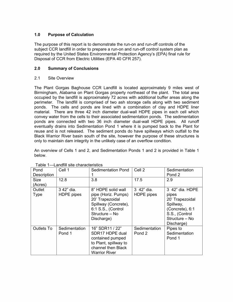
1.0 Purpose of Calculation The purpose of this report is to demonstrate the run-on and run-off controls of the subject CCR landfill in order to prepare a run-on and run-off control system plan as required by the United States Environmental Protection Agency’s (EPA) final rule for Disposal of CCR from Electric Utilities (EPA 40 CFR 257). 2.0 Summary of Conclusions
2.1 Site Overview
The Plant Gorgas Baghouse CCR Landfill is located approximately 9 miles west of Birmingham, Alabama on Plant Gorgas property northeast of the plant. The total area occupied by the landfill is approximately 72 acres with additional buffer areas along the perimeter. The landfill is comprised of two ash storage cells along with two sediment ponds. The cells and ponds are lined with a combination of clay and HDPE liner material. There are three 42 inch diameter dual-wall HDPE pipes in each cell which convey water from the cells to their associated sedimentation ponds. The sedimentation ponds are connected with two 36 inch diameter dual-wall HDPE pipes. All runoff eventually drains into Sedimentation Pond 1 where it is pumped back to the Plant for reuse and is not released. The sediment ponds do have spillways which outfall to the Black Warrior River basin south of the site, however the purpose of these structures is only to maintain dam integrity in the unlikely case of an overflow condition. An overview of Cells 1 and 2, and Sedimentation Ponds 1 and 2 is provided in Table 1 below. Table 1—Landfill site characteristics
Pond Description
Cell 1 Sedimentation Pond 1
Cell 2 Sedimentation Pond 2
Size (Acres)
12.8 3.8 17.5 2.9
Outlet Type
3 42” dia. HDPE pipes
8” HDPE solid wall pipe (Horiz. Pumps) 20’ Trapezoidal Spillway (Concrete), 6:1 S.S., (Control Structure – No Discharge)
3 42” dia. HDPE pipes
3 42” dia. HDPE pipes 20’ Trapezoidal Spillway, (Concrete), 6:1 S.S., (Control Structure – No Discharge)
Outlets To Sedimentation Pond 1
16” SDR11 / 22” SDR17 HDPE dual contained pumped to Plant, spillway to channel then Black Warrior River
Sedimentation Pond 2
Pipes to Sedimentation Pond 1

2.2 Run-on Control System Plan
There is no stormwater run-on into Cells 1 and 2 or Sedimentation Ponds 1 and 2 due to the construction of perimeter berm/roads at the outer boundaries. Any runoff that was directed to the landfill area was diverted by the initial design which now prevents any water encroachment.
2.3 Run-off Control System Plan
A hydrologic and hydraulic model was developed for the Plant Gorgas Baghouse CCR Landfill to determine the hydraulic capacity of the storage cells and sediment ponds. The design storm for the purposes of run-off control system plans is the 24-hour, 25-year rainfall event. The results of routing the design storm event through the landfill are presented in Table 2 below:
Table 2-Flood Routing Results for Plant Gorgas Baghouse CCR Landfill Plant Gorgas
Normal Pool El (ft)
Top of embankment El (ft)
Peak Water Surface Elevation (ft)
Freeboard* (ft)
Peak Inflow (cfs)
Peak Outflow (cfs)
Cell 1 No Pool
Varies, Low Pt. @ 512.0
501.4 10.6 N/A 102
Cell 2 No Pool
Varies, Low Pt. @ 512.5
504.4 8.1 N/A 119
Sediment Pond 1
483.0 512.0 494.2 17.8 221** N/A (pumped)
Sediment Pond 2
483.0 512.0 494.2 17.8 221** N/A (pumped)
* Freeboard is measured from the top of embankment to the peak water surfaceelevation** Combined Cell 1 Sedimentation Pond and Cell 2 Sedimentation Pond
3.0 Methodology
3.1 HYDROLOGIC ANALYSES
The design storm for all run-on/run-off analyses is a 24-hour, 25-year rainfall event. A summary of the design storm parameters and rainfall distribution methodology for these calculations is summarized below in Table 3.

Table 3. Plant Gorgas Baghouse CCR Landfill Design Storm Distribution Return Frequency (years)
Storm Duration (hours)
Rainfall Total (Inches)
Rainfall Source
Storm Distribution
25 24 7.15 NOAA Atlas 14
SCS Type III
The drainage area for the Plant Gorgas Baghouse CCR Landfill was delineated based on LiDAR data acquired for the Plant in 2011. Runoff characteristics were developed based on the Soil Conservation Service (SCS) methodologies as outlined in TR-55. An overall SCS curve number for the drainage area was developed based on methods prescribed in TR-55. Soil types were obtained from the Natural Resources Conservation Service. Land use areas were delineated based on aerial photography. Times of Concentration were also developed based on methodologies prescribed in TR-55. A table of the pertinent basin characteristics of the landfill is provided below in Tables 4(a) and 4(b).
Table 4(a) - Landfill Hydrologic Information (Cell 1 & Sedimentation Pond 1)
Drainage Basin Area (acres) 19.5
Hydrologic Curve Number, CN 90
Hydrologic Methodology SCS Method
Time of Concentration (minutes) 10.0
Hydrologic Software Hydraflow Hydrographs
Table 4(b) - Landfill Hydrologic Information (Cell 2 & Sedimentation Pond 2)
Drainage Basin Area (acres) 23.1
Hydrologic Curve Number, CN 89
Hydrologic Methodology SCS Method
Time of Concentration (minutes) 11.7
Hydrologic Software Hydraflow Hydrographs
Runoff values were determined by importing the characteristics developed above into a hydrologic model in Hydraflow Hydrographs Extension of AutoCad Civil 3D, 2013. 3.2 HYDRAULIC ANALYSES Storage values for the sedimentation ponds were determined by developing a stage-storage relationship utilizing contour data. The spillway system at the Plant Gorgas Baghouse CCR Landfill consists of primary spillways in the cells draining into the sediment ponds and primary trapezoidal weir spillways in each of the sediment ponds outfalling into a grassed drainage channel. The primary spillways for each cell consist of three 42 inch diameter HDPE pipes and the pond weir spillways are reinforced concrete, 20-foot wide crest by 1-foot deep with 6:1 slopes on either end providing access from the top of the pond. A summary of information for each spillway is presented below in Table 5.
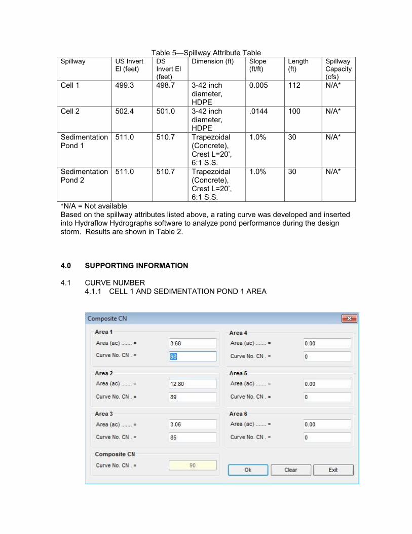
Table 5—Spillway Attribute Table Spillway US Invert
El (feet) DS Invert El (feet)
Dimension (ft) Slope (ft/ft)
Length (ft)
Spillway Capacity (cfs)
Cell 1 499.3 498.7 3-42 inch diameter, HDPE
0.005 112 N/A*
Cell 2 502.4 501.0 3-42 inch diameter, HDPE
.0144 100 N/A*
Sedimentation Pond 1
511.0 510.7 Trapezoidal (Concrete), Crest L=20’, 6:1 S.S.
1.0% 30 N/A*
Sedimentation Pond 2
511.0 510.7 Trapezoidal (Concrete), Crest L=20’, 6:1 S.S.
1.0% 30 N/A*
*N/A = Not available Based on the spillway attributes listed above, a rating curve was developed and inserted into Hydraflow Hydrographs software to analyze pond performance during the design storm. Results are shown in Table 2. 4.0 SUPPORTING INFORMATION
4.1 CURVE NUMBER
4.1.1 CELL 1 AND SEDIMENTATION POND 1 AREA

4.1.2 CELL 2 AND SEDIMENTATION POND 2 AREA
4.2 STAGE-STORAGE TABLE
4.2.1 SEDIMENTATION POND 1

4.2.2 SEDIMENTATION POND 2
4.2.3 COMBINED SEDIMENTATION PONDS 1 AND 2

4.3 TIME OF CONCENTRATION
4.3.1 CELL 1 TO SEDIMENTATION POND 1
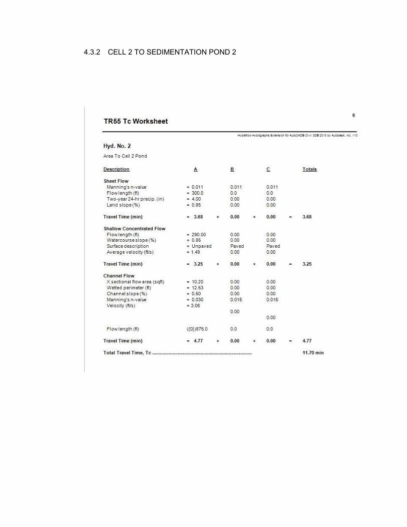
4.3.2 CELL 2 TO SEDIMENTATION POND 2

4.4 RESULTS 4.4.1 CELL 1 AND SEDIMENTATION POND 1
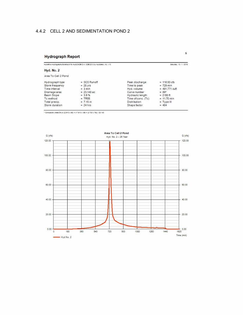
4.4.2 CELL 2 AND SEDIMENTATION POND 2
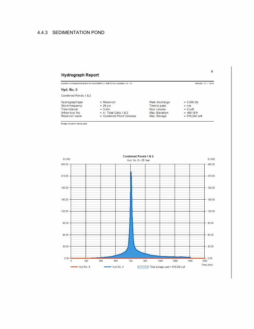
4.4.3 SEDIMENTATION POND
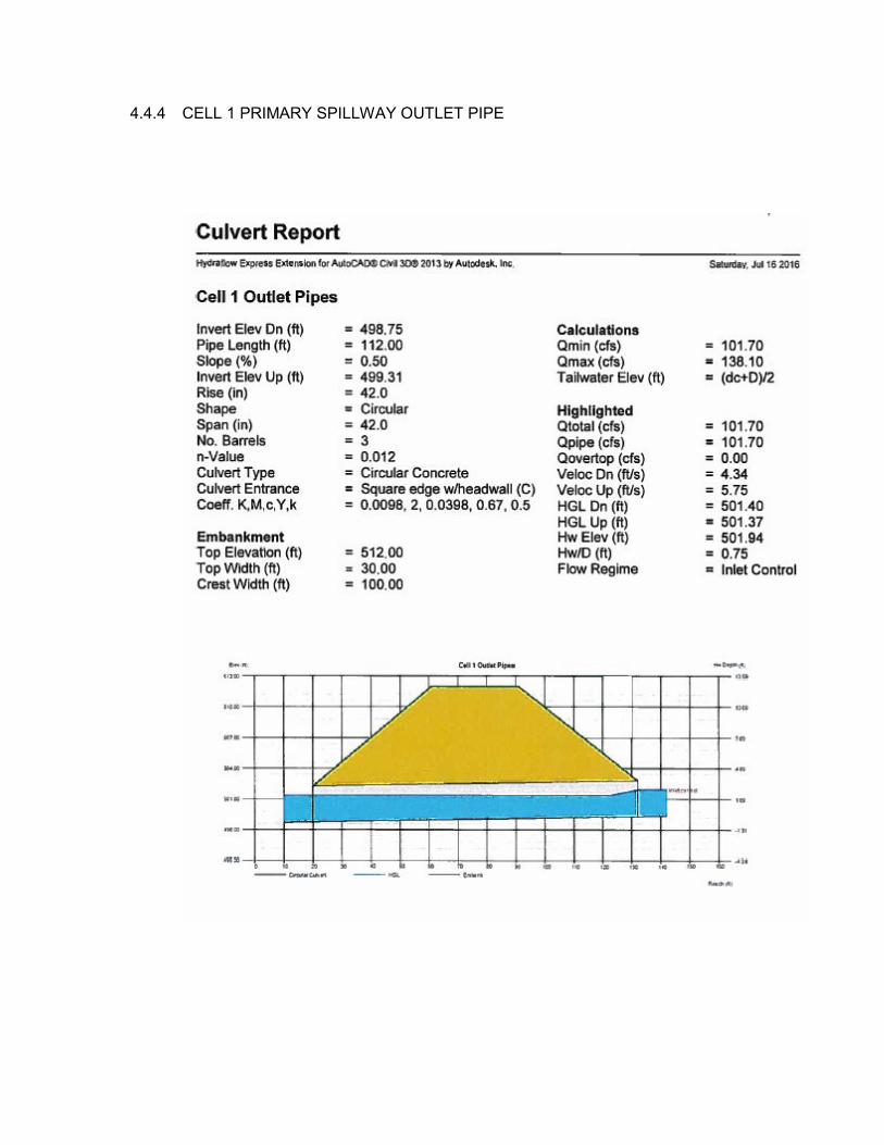
4.4.4 CELL 1 PRIMARY SPILLWAY OUTLET PIPE

4.4.5 CELL 2 PRIMARY SPILLWAY OUTLET PIPE

4.5 DRAINAGE BASIN