CCNA Semester 2 labs - IT...
82
CCNA Semester 2 labs Part 1 of 2 Labs for chapters 1 – 7
Transcript of CCNA Semester 2 labs - IT...
CCNA Semester 2 labs
Part 1 of 2
Labs for chapters 1 – 7

2.2.4.11 Lab - Configuring Switch Security Features
3.2.2.5 Lab - Configuring VLANs and Trunking
3.3.2.2 Lab - Implementing VLAN Security
4.1.4.6 Lab - Configuring Basic Router Settings with IOS CLI
5.1.3.7 Lab - Configuring 802.1Q Trunk-Based Inter-VLAN Routing
6.2.2.5 Lab - Configuring IPv4 Static and Default Routes
6.2.4.5 Lab - Configuring IPv6 Static and Default Routes
6.4.2.5 Lab - Calculating Summary Routes with IPv4 and IPv6
6.5.2.5 Lab - Troubleshooting IPv4 and IPv6 Static Routes
7.3.2.4 Lab - Configuring Basic RIPv2 and RIPng
© 2013 Cisco and/or its affiliates. All rights reserved. This document is Cisco Public. Page 1 of 8
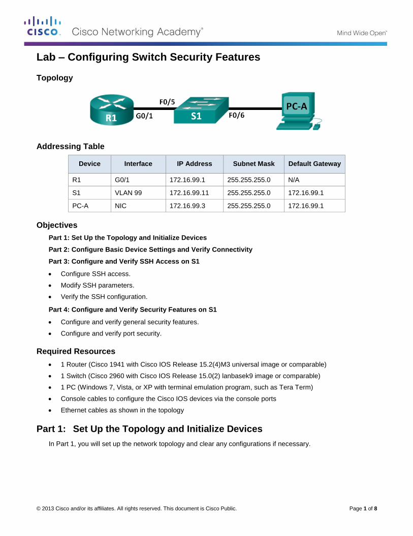
Lab – Configuring Switch Security Features
Topology
Addressing Table
Device Interface IP Address Subnet Mask Default Gateway
R1 G0/1 172.16.99.1 255.255.255.0 N/A
S1 VLAN 99 172.16.99.11 255.255.255.0 172.16.99.1
PC-A NIC 172.16.99.3 255.255.255.0 172.16.99.1
Objectives
Part 1: Set Up the Topology and Initialize Devices
Part 2: Configure Basic Device Settings and Verify Connectivity
Part 3: Configure and Verify SSH Access on S1
Configure SSH access.
Modify SSH parameters.
Verify the SSH configuration.
Part 4: Configure and Verify Security Features on S1
Configure and verify general security features.
Configure and verify port security.
Required Resources
1 Router (Cisco 1941 with Cisco IOS Release 15.2(4)M3 universal image or comparable)
1 Switch (Cisco 2960 with Cisco IOS Release 15.0(2) lanbasek9 image or comparable)
1 PC (Windows 7, Vista, or XP with terminal emulation program, such as Tera Term)
Console cables to configure the Cisco IOS devices via the console ports
Ethernet cables as shown in the topology
Part 1: Set Up the Topology and Initialize Devices
In Part 1, you will set up the network topology and clear any configurations if necessary.
Lab – Configuring Switch Security Features
© 2013 Cisco and/or its affiliates. All rights reserved. This document is Cisco Public. Page 2 of 8
Step 1: Cable the network as shown in the topology.
Step 2: Initialize and reload the router and switch.
If configuration files were previously saved on the router or switch, initialize and reload these devices back to their basic configurations.
Part 2: Configure Basic Device Settings and Verify Connectivity
In Part 2, you configure basic settings on the router, switch, and PC. Refer to the Topology and Addressing Table at the beginning of this lab for device names and address information.
Step 1: Configure an IP address on PC-A.
Step 2: Configure basic settings on R1.
a. Configure the device name.
b. Disable DNS lookup.
c. Configure interface IP address as shown in the Addressing Table.
d. Assign class as the privileged EXEC mode password.
e. Assign cisco as the console and vty password and enable login.
f. Encrypt plain text passwords.
g. Save the running configuration to startup configuration.
Step 3: Configure basic settings on S1.
A good security practice is to assign the management IP address of the switch to a VLAN other than VLAN 1 (or any other data VLAN with end users). In this step, you will create VLAN 99 on the switch and assign it an IP address.
a. Configure the device name.
b. Disable DNS lookup.
c. Assign class as the privileged EXEC mode password.
d. Assign cisco as the console and vty password and then enable login.
e. Configure a default gateway for S1 using the IP address of R1.
f. Encrypt plain text passwords.
g. Save the running configuration to startup configuration.
h. Create VLAN 99 on the switch and name it Management.
S1(config)# vlan 99
S1(config-vlan)# name Management
S1(config-vlan)# exit
S1(config)#
i. Configure the VLAN 99 management interface IP address, as shown in the Addressing Table, and enable the interface.
S1(config)# interface vlan 99
S1(config-if)# ip address 172.16.99.11 255.255.255.0
S1(config-if)# no shutdown
Lab – Configuring Switch Security Features
© 2013 Cisco and/or its affiliates. All rights reserved. This document is Cisco Public. Page 3 of 8
S1(config-if)# end
S1#
j. Issue the show vlan command on S1. What is the status of VLAN 99? ______________________
k. Issue the show ip interface brief command on S1. What is the status and protocol for management interface VLAN 99?
____________________________________________________________________________________
Why is the protocol down, even though you issued the no shutdown command for interface VLAN 99?
____________________________________________________________________________________
l. Assign ports F0/5 and F0/6 to VLAN 99 on the switch.
S1# config t
S1(config)# interface f0/5
S1(config-if)# switchport mode access
S1(config-if)# switchport access vlan 99
S1(config-if)# interface f0/6
S1(config-if)# switchport mode access
S1(config-if)# switchport access vlan 99
S1(config-if)# end
m. Issue the show ip interface brief command on S1. What is the status and protocol showing for interface VLAN 99? _______________________________________________
Note: There may be a delay while the port states converge.
Step 4: Verify connectivity between devices.
a. From PC-A, ping the default gateway address on R1. Were your pings successful? ______________
b. From PC-A, ping the management address of S1. Were your pings successful? ______________
c. From S1, ping the default gateway address on R1. Were your pings successful? ______________
d. From PC-A, open a web browser and go to http://172.16.99.11. If it prompts you for a username and password, leave the username blank and use class for the password. If it prompts for secured connection, answer No. Were you able to access the web interface on S1? ______________
e. Close the browser session on PC-A.
Note: The non-secure web interface (HTTP server) on a Cisco 2960 switch is enabled by default. A common security measure is to disable this service, as described in Part 4.
Part 3: Configure and Verify SSH Access on S1
Step 1: Configure SSH access on S1.
a. Enable SSH on S1. From global configuration mode, create a domain name of CCNA-Lab.com.
S1(config)# ip domain-name CCNA-Lab.com
b. Create a local user database entry for use when connecting to the switch via SSH. The user should have administrative level access.
Note: The password used here is NOT a strong password. It is merely being used for lab purposes.
S1(config)# username admin privilege 15 secret sshadmin

Lab – Configuring Switch Security Features
© 2013 Cisco and/or its affiliates. All rights reserved. This document is Cisco Public. Page 4 of 8
c. Configure the transport input for the vty lines to allow SSH connections only, and use the local database for authentication.
S1(config)# line vty 0 15
S1(config-line)# transport input ssh
S1(config-line)# login local
S1(config-line)# exit
d. Generate an RSA crypto key using a modulus of 1024 bits.
S1(config)# crypto key generate rsa modulus 1024
The name for the keys will be: S1.CCNA-Lab.com
% The key modulus size is 1024 bits
% Generating 1024 bit RSA keys, keys will be non-exportable...
[OK] (elapsed time was 3 seconds)
S1(config)#
S1(config)# end
e. Verify the SSH configuration and answer the questions below.
S1# show ip ssh
What version of SSH is the switch using? _______________________
How many authentication attempts does SSH allow? _______________________
What is the default timeout setting for SSH? _______________________
Step 2: Modify the SSH configuration on S1.
Modify the default SSH configuration.
S1# config t
S1(config)# ip ssh time-out 75
S1(config)# ip ssh authentication-retries 2
How many authentication attempts does SSH allow? _______________________
What is the timeout setting for SSH? _______________________
Step 3: Verify the SSH configuration on S1.
a. Using SSH client software on PC-A (such as Tera Term), open an SSH connection to S1. If you receive a message on your SSH client regarding the host key, accept it. Log in with admin for username and sshadmin for the password.
Was the connection successful? _________________________
What prompt was displayed on S1? Why?
____________________________________________________________________________________
____________________________________________________________________________________
b. Type exit to end the SSH session on S1.

Lab – Configuring Switch Security Features
© 2013 Cisco and/or its affiliates. All rights reserved. This document is Cisco Public. Page 5 of 8
Part 4: Configure and Verify Security Features on S1
In Part 4, you will shut down unused ports, turn off certain services running on the switch, and configure port security based on MAC addresses. Switches can be subject to MAC address table overflow attacks, MAC spoofing attacks, and unauthorized connections to switch ports. You will configure port security to limit the number of MAC addresses that can be learned on a switch port and disable the port if that number is exceeded.
Step 1: Configure general security features on S1.
a. Configure a message of the day (MOTD) banner on S1 with an appropriate security warning message.
b. Issue a show ip interface brief command on S1. What physical ports are up?
____________________________________________________________________________________
c. Shut down all unused physical ports on the switch. Use the interface range command.
S1(config)# interface range f0/1 – 4
S1(config-if-range)# shutdown
S1(config-if-range)# interface range f0/7 – 24
S1(config-if-range)# shutdown
S1(config-if-range)# interface range g0/1 – 2
S1(config-if-range)# shutdown
S1(config-if-range)# end
S1#
d. Issue the show ip interface brief command on S1. What is the status of ports F0/1 to F0/4?
____________________________________________________________________________________
e. Issue the show ip http server status command.
What is the HTTP server status? ___________________________
What server port is it using? ___________________________
What is the HTTP secure server status? ___________________________
What secure server port is it using? ___________________________
f. HTTP sessions send everything in plain text. You will disable the HTTP service running on S1.
S1(config)# no ip http server
g. From PC-A, open a web browser session to http://172.16.99.11. What was your result?
____________________________________________________________________________________
h. From PC-A, open a secure web browser session at https://172.16.99.11. Accept the certificate. Log in with no username and a password of class. What was your result?
____________________________________________________________________________________
i. Close the web session on PC-A.
Step 2: Configure and verify port security on S1.
a. Record the R1 G0/1 MAC address. From the R1 CLI, use the show interface g0/1 command and record the MAC address of the interface.
R1# show interface g0/1
GigabitEthernet0/1 is up, line protocol is up

Lab – Configuring Switch Security Features
© 2013 Cisco and/or its affiliates. All rights reserved. This document is Cisco Public. Page 6 of 8
Hardware is CN Gigabit Ethernet, address is 30f7.0da3.1821 (bia
3047.0da3.1821)
What is the MAC address of the R1 G0/1 interface? __________________________________________
b. From the S1 CLI, issue a show mac address-table command from privileged EXEC mode. Find the dynamic entries for ports F0/5 and F0/6. Record them below.
F0/5 MAC address: ______________________________________________________
F0/6 MAC address: ______________________________________________________
c. Configure basic port security.
Note: This procedure would normally be performed on all access ports on the switch. F0/5 is shown here as an example.
1) From the S1 CLI, enter interface configuration mode for the port that connects to R1.
S1(config)# interface f0/5
2) Shut down the port.
S1(config-if)# shutdown
3) Enable port security on F0/5.
S1(config-if)# switchport port-security
Note: Entering the switchport port-security command sets the maximum MAC addresses to 1 and the violation action to shutdown. The switchport port-security maximum and switchport port-security violation commands can be used to change the default behavior.
4) Configure a static entry for the MAC address of R1 G0/1 interface recorded in Step 2a.
S1(config-if)# switchport port-security mac-address xxxx.xxxx.xxxx
(xxxx.xxxx.xxxx is the actual MAC address of the router G0/1 interface)
Note: Optionally, you can use the switchport port-security mac-address sticky command to
add all the secure MAC addresses that are dynamically learned on a port (up to the maximum set) to the switch running configuration.
5) Enable the switch port.
S1(config-if)# no shutdown
S1(config-if)# end
d. Verify port security on S1 F0/5 by issuing a show port-security interface command.
S1# show port-security interface f0/5
Port Security : Enabled
Port Status : Secure-up
Violation Mode : Shutdown
Aging Time : 0 mins
Aging Type : Absolute
SecureStatic Address Aging : Disabled
Maximum MAC Addresses : 1
Total MAC Addresses : 1
Configured MAC Addresses : 1
Sticky MAC Addresses : 0
Last Source Address:Vlan : 0000.0000.0000:0
Security Violation Count : 0

Lab – Configuring Switch Security Features
© 2013 Cisco and/or its affiliates. All rights reserved. This document is Cisco Public. Page 7 of 8
What is the port status of F0/5? ___________________________
e. From R1 command prompt, ping PC-A to verify connectivity.
R1# ping 172.16.99.3
f. You will now violate security by changing the MAC address on the router interface. Enter interface configuration mode for G0/1 and shut it down.
R1# config t
R1(config)# interface g0/1
R1(config-if)# shutdown
g. Configure a new MAC address for the interface, using aaaa.bbbb.cccc as the address.
R1(config-if)# mac-address aaaa.bbbb.cccc
h. If possible, have a console connection open on S1 at the same time that you do this step. You will see various messages displayed on the console connection to S1 indicating a security violation. Enable the G0/1 interface on R1.
R1(config-if)# no shutdown
i. From R1 privileged EXEC mode, ping PC-A. Was the ping successful? Why or why not?
____________________________________________________________________________________
j. On the switch, verify port security with the following commands shown below.
S1# show port-security
Secure Port MaxSecureAddr CurrentAddr SecurityViolation Security Action
(Count) (Count) (Count)
--------------------------------------------------------------------
Fa0/5 1 1 1 Shutdown
----------------------------------------------------------------------
Total Addresses in System (excluding one mac per port) :0
Max Addresses limit in System (excluding one mac per port) :8192
S1# show port-security interface f0/5
Port Security : Enabled
Port Status : Secure-shutdown
Violation Mode : Shutdown
Aging Time : 0 mins
Aging Type : Absolute
SecureStatic Address Aging : Disabled
Maximum MAC Addresses : 1
Total MAC Addresses : 1
Configured MAC Addresses : 1
Sticky MAC Addresses : 0
Last Source Address:Vlan : aaaa.bbbb.cccc:99
Security Violation Count : 1
S1# show interface f0/5
FastEthernet0/5 is down, line protocol is down (err-disabled)
Hardware is Fast Ethernet, address is 0cd9.96e2.3d05 (bia 0cd9.96e2.3d05)
MTU 1500 bytes, BW 10000 Kbit/sec, DLY 1000 usec,
reliability 255/255, txload 1/255, rxload 1/255

Lab – Configuring Switch Security Features
© 2013 Cisco and/or its affiliates. All rights reserved. This document is Cisco Public. Page 8 of 8
<output omitted>
S1# show port-security address
Secure Mac Address Table
------------------------------------------------------------------------
Vlan Mac Address Type Ports Remaining Age
(mins)
---- ----------- ---- ----- -------------
99 30f7.0da3.1821 SecureConfigured Fa0/5 -
-----------------------------------------------------------------------
Total Addresses in System (excluding one mac per port) :0
Max Addresses limit in System (excluding one mac per port) :8192
k. On the router, shut down the G0/1 interface, remove the hard-coded MAC address from the router, and re-enable the G0/1 interface.
R1(config-if)# shutdown
R1(config-if)# no mac-address aaaa.bbbb.cccc
R1(config-if)# no shutdown
R1(config-if)# end
l. From R1, ping PC-A again at 172.16.99.3. Was the ping successful? _________________
m. On the Switch, issue the show interface f0/5 command to determine the cause of ping failure. Record your findings.
____________________________________________________________________________________
n. Clear the S1 F0/5 error disabled status.
S1# config t
S1(config)# interface f0/5
S1(config-if)# shutdown
S1(config-if)# no shutdown
Note: There may be a delay while the port states converge.
o. Issue the show interface f0/5 command on S1 to verify F0/5 is no longer in error disabled mode.
S1# show interface f0/5
FastEthernet0/5 is up, line protocol is up (connected)
Hardware is Fast Ethernet, address is 0023.5d59.9185 (bia 0023.5d59.9185)
MTU 1500 bytes, BW 100000 Kbit/sec, DLY 100 usec,
reliability 255/255, txload 1/255, rxload 1/255
p. From the R1 command prompt, ping PC-A again. You should be successful.
Reflection
1. Why would you enable port security on a switch?
_______________________________________________________________________________________
_______________________________________________________________________________________
2. Why should unused ports on a switch be disabled?
_______________________________________________________________________________________
_______________________________________________________________________________________
© 2013 Cisco and/or its affiliates. All rights reserved. This document is Cisco Public. Page 1 of 1
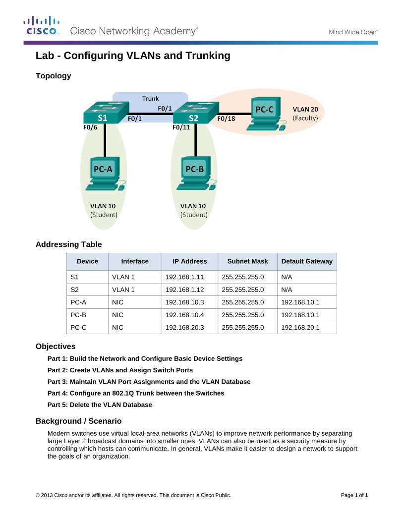
Lab - Configuring VLANs and Trunking
Topology
Addressing Table
Device Interface IP Address Subnet Mask Default Gateway
S1 VLAN 1 192.168.1.11 255.255.255.0 N/A
S2 VLAN 1 192.168.1.12 255.255.255.0 N/A
PC-A NIC 192.168.10.3 255.255.255.0 192.168.10.1
PC-B NIC 192.168.10.4 255.255.255.0 192.168.10.1
PC-C NIC 192.168.20.3 255.255.255.0 192.168.20.1
Objectives
Part 1: Build the Network and Configure Basic Device Settings
Part 2: Create VLANs and Assign Switch Ports
Part 3: Maintain VLAN Port Assignments and the VLAN Database
Part 4: Configure an 802.1Q Trunk between the Switches
Part 5: Delete the VLAN Database
Background / Scenario
Modern switches use virtual local-area networks (VLANs) to improve network performance by separating large Layer 2 broadcast domains into smaller ones. VLANs can also be used as a security measure by controlling which hosts can communicate. In general, VLANs make it easier to design a network to support the goals of an organization.

Lab - Configuring VLANs and Trunking
© 2013 Cisco and/or its affiliates. All rights reserved. This document is Cisco Public. Page 2 of 2
VLAN trunks are used to span VLANs across multiple devices. Trunks allow the traffic from multiple VLANS to travel over a single link, while keeping the VLAN identification and segmentation intact.
In this lab, you will create VLANs on both switches in the topology, assign VLANs to switch access ports, verify that VLANs are working as expected, and then create a VLAN trunk between the two switches to allow hosts in the same VLAN to communicate through the trunk, regardless of which switch the host is actually attached to.
Note: The switches used are Cisco Catalyst 2960s with Cisco IOS Release 15.0(2) (lanbasek9 image). Other switches and Cisco IOS versions can be used. Depending on the model and Cisco IOS version, the commands available and output produced might vary from what is shown in the labs.
Note: Ensure that the switches have been erased and have no startup configurations. If you are unsure contact your instructor.
Required Resources
2 Switches (Cisco 2960 with Cisco IOS Release 15.0(2) lanbasek9 image or comparable)
3 PCs (Windows 7, Vista, or XP with terminal emulation program, such as Tera Term)
Console cables to configure the Cisco IOS devices via the console ports
Ethernet cables as shown in the topology
Part 1: Build the Network and Configure Basic Device Settings
In Part 1, you will set up the network topology and configure basic settings on the PC hosts and switches.
Step 1: Cable the network as shown in the topology.
Attach the devices as shown in the topology diagram, and cable as necessary.
Step 2: Initialize and reload the switches as necessary.
Step 3: Configure basic settings for each switch.
a. Disable DNS lookup.
b. Configure device name as shown in the topology.
c. Assign class as the privileged EXEC password.
d. Assign cisco as the console and vty passwords and enable login for console and vty lines.
e. Configure logging synchronous for the console line.
f. Configure a MOTD banner to warn users that unauthorized access is prohibited.
g. Configure the IP address listed in the Addressing Table for VLAN 1 on both switches.
h. Administratively deactivate all unused ports on the switch.
i. Copy the running configuration to the startup configuration.
Step 4: Configure PC hosts.
Refer to the Addressing Table for PC host address information.
Step 5: Test connectivity.
Verify that the PC hosts can ping one another.
Lab - Configuring VLANs and Trunking
© 2013 Cisco and/or its affiliates. All rights reserved. This document is Cisco Public. Page 3 of 3
Note: It may be necessary to disable the PCs firewall to ping between PCs.
Can PC-A ping PC-B? ______________
Can PC-A ping PC-C? ______________
Can PC-A ping S1? ______________
Can PC-B ping PC-C? ______________
Can PC-B ping S2? ______________
Can PC-C ping S2? ______________
Can S1 ping S2? ______________
If you answered no to any of the above questions, why were the pings unsuccessful?
_______________________________________________________________________________________
_______________________________________________________________________________________
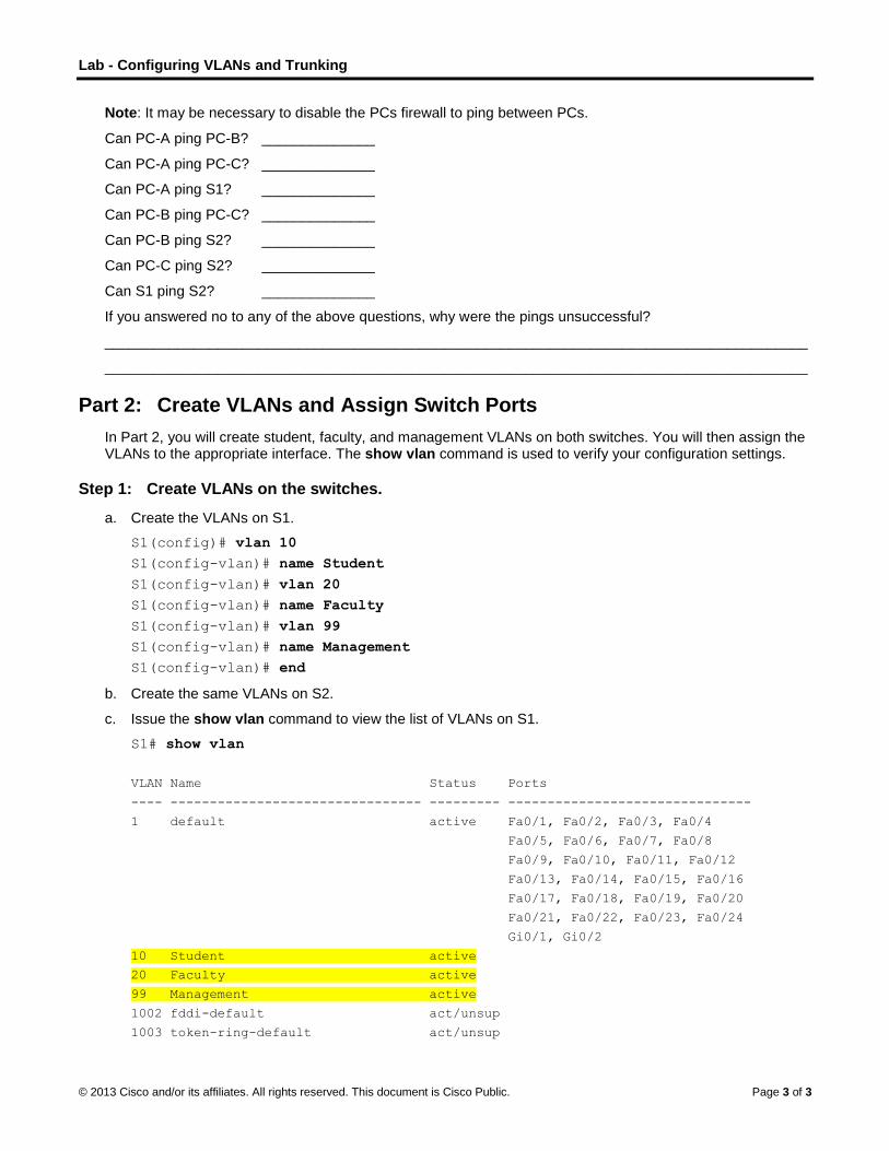
Part 2: Create VLANs and Assign Switch Ports
In Part 2, you will create student, faculty, and management VLANs on both switches. You will then assign the VLANs to the appropriate interface. The show vlan command is used to verify your configuration settings.
Step 1: Create VLANs on the switches.
a. Create the VLANs on S1.
S1(config)# vlan 10
S1(config-vlan)# name Student
S1(config-vlan)# vlan 20
S1(config-vlan)# name Faculty
S1(config-vlan)# vlan 99
S1(config-vlan)# name Management
S1(config-vlan)# end
b. Create the same VLANs on S2.
c. Issue the show vlan command to view the list of VLANs on S1.
S1# show vlan
VLAN Name Status Ports
---- -------------------------------- --------- -------------------------------
1 default active Fa0/1, Fa0/2, Fa0/3, Fa0/4
Fa0/5, Fa0/6, Fa0/7, Fa0/8
Fa0/9, Fa0/10, Fa0/11, Fa0/12
Fa0/13, Fa0/14, Fa0/15, Fa0/16
Fa0/17, Fa0/18, Fa0/19, Fa0/20
Fa0/21, Fa0/22, Fa0/23, Fa0/24
Gi0/1, Gi0/2
10 Student active
20 Faculty active
99 Management active
1002 fddi-default act/unsup
1003 token-ring-default act/unsup
Lab - Configuring VLANs and Trunking
© 2013 Cisco and/or its affiliates. All rights reserved. This document is Cisco Public. Page 4 of 4
1004 fddinet-default act/unsup
1005 trnet-default act/unsup
VLAN Type SAID MTU Parent RingNo BridgeNo Stp BrdgMode Trans1 Trans2
---- ----- ---------- ----- ------ ------ -------- ---- -------- ------ ------
1 enet 100001 1500 - - - - - 0 0
10 enet 100010 1500 - - - - - 0 0
20 enet 100020 1500 - - - - - 0 0
99 enet 100099 1500 - - - - - 0 0
VLAN Type SAID MTU Parent RingNo BridgeNo Stp BrdgMode Trans1 Trans2
---- ----- ---------- ----- ------ ------ -------- ---- -------- ------ ------
1002 fddi 101002 1500 - - - - - 0 0
1003 tr 101003 1500 - - - - - 0 0
1004 fdnet 101004 1500 - - - ieee - 0 0
1005 trnet 101005 1500 - - - ibm - 0 0
Remote SPAN VLANs
------------------------------------------------------------------------------
Primary Secondary Type Ports
------- --------- ----------------- ------------------------------------------
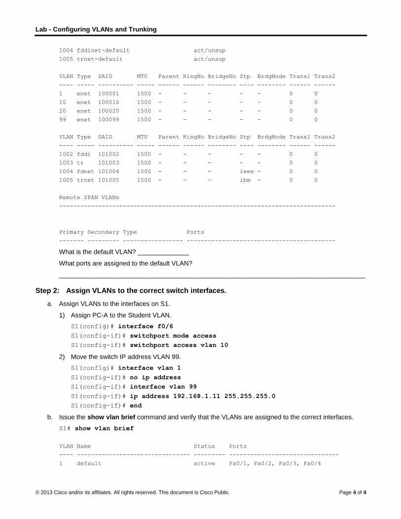
What is the default VLAN? ______________
What ports are assigned to the default VLAN?
____________________________________________________________________________________
Step 2: Assign VLANs to the correct switch interfaces.
a. Assign VLANs to the interfaces on S1.
1) Assign PC-A to the Student VLAN.
S1(config)# interface f0/6
S1(config-if)# switchport mode access
S1(config-if)# switchport access vlan 10
2) Move the switch IP address VLAN 99.
S1(config)# interface vlan 1
S1(config-if)# no ip address
S1(config-if)# interface vlan 99
S1(config-if)# ip address 192.168.1.11 255.255.255.0
S1(config-if)# end
b. Issue the show vlan brief command and verify that the VLANs are assigned to the correct interfaces.
S1# show vlan brief
VLAN Name Status Ports
---- -------------------------------- --------- -------------------------------
1 default active Fa0/1, Fa0/2, Fa0/3, Fa0/4

Lab - Configuring VLANs and Trunking
© 2013 Cisco and/or its affiliates. All rights reserved. This document is Cisco Public. Page 5 of 5
Fa0/5, Fa0/7, Fa0/8, Fa0/9
Fa0/10, Fa0/11, Fa0/12, Fa0/13
Fa0/14, Fa0/15, Fa0/16, Fa0/17
Fa0/18, Fa0/19, Fa0/20, Fa0/21
Fa0/22, Fa0/23, Fa0/24, Gi0/1
Gi0/2
10 Student active Fa0/6
20 Faculty active
99 Management active
1002 fddi-default act/unsup
1003 token-ring-default act/unsup
1004 fddinet-default act/unsup
1005 trnet-default act/unsup
c. Issue the show ip interfaces brief command.
What is the status of VLAN 99? Why?
____________________________________________________________________________________
d. Use the Topology to assign VLANs to the appropriate ports on S2.
e. Remove the IP address for VLAN 1 on S2.
f. Configure an IP address for VLAN 99 on S2 according to the Addressing Table.
g. Use the show vlan brief command to verify that the VLANs are assigned to the correct interfaces.
S2# show vlan brief
VLAN Name Status Ports
---- -------------------------------- --------- -------------------------------
1 default active Fa0/1, Fa0/2, Fa0/3, Fa0/4
Fa0/5, Fa0/6, Fa0/7, Fa0/8
Fa0/9, Fa0/10, Fa0/12, Fa0/13
Fa0/14, Fa0/15, Fa0/16, Fa0/17
Fa0/19, Fa0/20, Fa0/21, Fa0/22
Fa0/23, Fa0/24, Gi0/1, Gi0/2
10 Student active Fa0/11
20 Faculty active Fa0/18
99 Management active
1002 fddi-default act/unsup
1003 token-ring-default act/unsup
1004 fddinet-default act/unsup
1005 trnet-default act/unsup
Is PC-A able to ping PC-B? Why?
____________________________________________________________________________________
Is S1 able to ping S2? Why?
____________________________________________________________________________________
____________________________________________________________________________________

Lab - Configuring VLANs and Trunking
© 2013 Cisco and/or its affiliates. All rights reserved. This document is Cisco Public. Page 6 of 6
Part 3: Maintain VLAN Port Assignments and the VLAN Database
In Part 3, you will change VLAN assignments to ports and remove VLANs from the VLAN database.
Step 1: Assign a VLAN to multiple interfaces.
a. On S1, assign interfaces F0/11 – 24 to VLAN 10.
S1(config)# interface range f0/11-24
S1(config-if-range)# switchport mode access
S1(config-if-range)# switchport access vlan 10
S1(config-if-range)# end
b. Issue the show vlan brief command to verify VLAN assignments.
c. Reassign F0/11 and F0/21 to VLAN 20.
d. Verify that VLAN assignments are correct.
Step 2: Remove a VLAN assignment from an interface.
a. Use the no switchport access vlan command to remove the VLAN 10 assignment to F0/24.
S1(config)# interface f0/24
S1(config-if)# no switchport access vlan
S1(config-if)# end
b. Verify that the VLAN change was made.
Which VLAN is F0/24 is now associated with? ______________
Step 3: Remove a VLAN ID from the VLAN database.
a. Add VLAN 30 to interface F0/24 without issuing the VLAN command.
S1(config)# interface f0/24
S1(config-if)# switchport access vlan 30
% Access VLAN does not exist. Creating vlan 30
Note: Current switch technology no longer requires that the vlan command be issued to add a VLAN to the database. By assigning an unknown VLAN to a port, the VLAN adds to the VLAN database.
b. Verify that the new VLAN is displayed in the VLAN table.
S1# show vlan brief
VLAN Name Status Ports
---- -------------------------------- --------- -------------------------------
1 default active Fa0/1, Fa0/2, Fa0/3, Fa0/4
Fa0/5, Fa0/6, Fa0/7, Fa0/8
Fa0/9, Fa0/10, Gi0/1, Gi0/2
10 Student active Fa0/12, Fa0/13, Fa0/14, Fa0/15
Fa0/16, Fa0/17, Fa0/18, Fa0/19
Fa0/20, Fa0/22, Fa0/23
20 Faculty active Fa0/11, Fa0/21
30 VLAN0030 active Fa0/24
99 Management active
1002 fddi-default act/unsup

Lab - Configuring VLANs and Trunking
© 2013 Cisco and/or its affiliates. All rights reserved. This document is Cisco Public. Page 7 of 7
1003 token-ring-default act/unsup
1004 fddinet-default act/unsup
1005 trnet-default act/unsup
What is the default name of VLAN 30? ______________
c. Use the no vlan 30 command to remove VLAN 30 from the VLAN database.
S1(config)# no vlan 30
S1(config)# end
d. Issue the show vlan brief command. F0/24 was assigned to VLAN 30.
After deleting VLAN 30, what VLAN is port F0/24 assigned to? What happens to the traffic destined to the host attached to F0/24?
____________________________________________________________________________________
S1# show vlan brief
VLAN Name Status Ports
---- -------------------------------- --------- -------------------------------
1 default active Fa0/1, Fa0/2, Fa0/3, Fa0/4
Fa0/5, Fa0/6, Fa0/7, Fa0/8
Fa0/9, Fa0/10, Gi0/1, Gi0/2
10 Student active Fa0/12, Fa0/13, Fa0/14, Fa0/15
Fa0/16, Fa0/17, Fa0/18, Fa0/19
Fa0/20, Fa0/22, Fa0/23
20 Faculty active Fa0/11, Fa0/21
99 Management active
1002 fddi-default act/unsup
1003 token-ring-default act/unsup
1004 fddinet-default act/unsup
1005 trnet-default act/unsup
e. Issue the no switchport access vlan command on interface F0/24.
f. Issue the show vlan brief command to determine the VLAN assignment for F0/24. To which VLAN is F0/24 assigned?
____________________________________________________________________________________
Note: Before removing a VLAN from the database, it is recommended that you reassign all the ports assigned to that VLAN.
Why should you reassign a port to another VLAN before removing the VLAN from the VLAN database?
____________________________________________________________________________________
____________________________________________________________________________________
____________________________________________________________________________________
Part 4: Configure an 802.1Q Trunk Between the Switches
In Part 4, you will configure interface F0/1 to use the Dynamic Trunking Protocol (DTP) to allow it to negotiate the trunk mode. After this has been accomplished and verified, you will disable DTP on interface F0/1 and manually configure it as a trunk.

Lab - Configuring VLANs and Trunking
© 2013 Cisco and/or its affiliates. All rights reserved. This document is Cisco Public. Page 8 of 8
Step 1: Use DTP to initiate trunking on F0/1.
The default DTP mode of a 2960 switch port is dynamic auto. This allows the interface to convert the link to a trunk if the neighboring interface is set to trunk or dynamic desirable mode.
a. Set F0/1 on S1 to negotiate trunk mode.
S1(config)# interface f0/1
S1(config-if)# switchport mode dynamic desirable
*Mar 1 05:07:28.746: %LINEPROTO-5-UPDOWN: Line protocol on Interface Vlan1, changed
state to down
*Mar 1 05:07:29.744: %LINEPROTO-5-UPDOWN: Line protocol on Interface FastEthernet0/1,
changed state to down
S1(config-if)#
*Mar 1 05:07:32.772: %LINEPROTO-5-UPDOWN: Line protocol on Interface FastEthernet0/1,
changed state to up
S1(config-if)#
*Mar 1 05:08:01.789: %LINEPROTO-5-UPDOWN: Line protocol on Interface Vlan99, changed
state to up
*Mar 1 05:08:01.797: %LINEPROTO-5-UPDOWN: Line protocol on Interface Vlan1, changed
state to up
You should also receive link status messages on S2.
S2#
*Mar 1 05:07:29.794: %LINEPROTO-5-UPDOWN: Line protocol on Interface FastEthernet0/1,
changed state to down
S2#
*Mar 1 05:07:32.823: %LINEPROTO-5-UPDOWN: Line protocol on Interface FastEthernet0/1,
changed state to up
S2#
*Mar 1 05:08:01.839: %LINEPROTO-5-UPDOWN: Line protocol on Interface Vlan99, changed
state to up
*Mar 1 05:08:01.850: %LINEPROTO-5-UPDOWN: Line protocol on Interface Vlan1, changed
state to up
b. Issue the show vlan brief command on S1 and S2. Interface F0/1 is no longer assigned to VLAN 1. Trunked interfaces are not listed in the VLAN table.
S1# show vlan brief
VLAN Name Status Ports
---- -------------------------------- --------- -------------------------------
1 default active Fa0/2, Fa0/3, Fa0/4, Fa0/5
Fa0/7, Fa0/8, Fa0/9, Fa0/10
Fa0/24, Gi0/1, Gi0/2
10 Student active Fa0/6, Fa0/12, Fa0/13, Fa0/14
Fa0/15, Fa0/16, Fa0/17, Fa0/18
Fa0/19, Fa0/20, Fa0/22, Fa0/23
20 Faculty active Fa0/11, Fa0/21
99 Management active
1002 fddi-default act/unsup
1003 token-ring-default act/unsup
1004 fddinet-default act/unsup
1005 trnet-default act/unsup
Lab - Configuring VLANs and Trunking
© 2013 Cisco and/or its affiliates. All rights reserved. This document is Cisco Public. Page 9 of 9
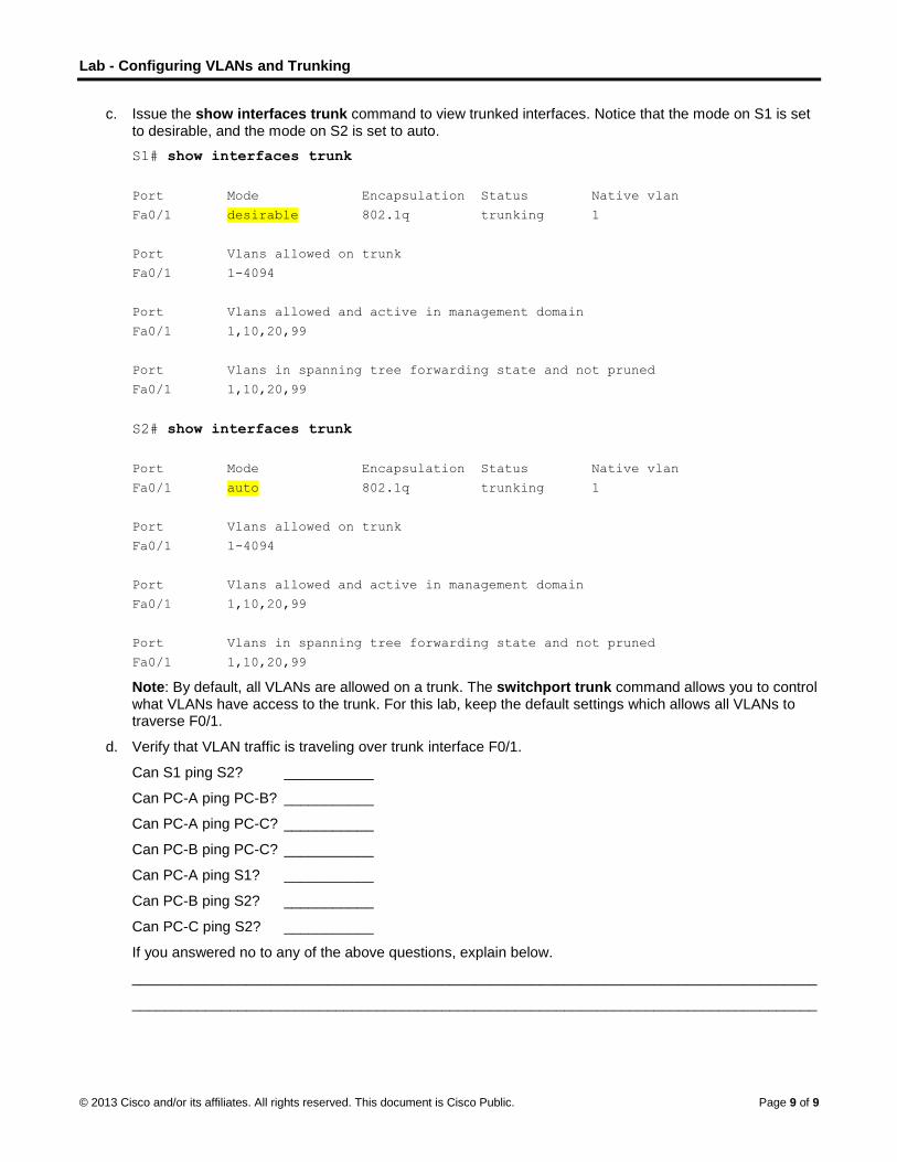
c. Issue the show interfaces trunk command to view trunked interfaces. Notice that the mode on S1 is set to desirable, and the mode on S2 is set to auto.
S1# show interfaces trunk
Port Mode Encapsulation Status Native vlan
Fa0/1 desirable 802.1q trunking 1
Port Vlans allowed on trunk
Fa0/1 1-4094
Port Vlans allowed and active in management domain
Fa0/1 1,10,20,99
Port Vlans in spanning tree forwarding state and not pruned
Fa0/1 1,10,20,99
S2# show interfaces trunk
Port Mode Encapsulation Status Native vlan
Fa0/1 auto 802.1q trunking 1
Port Vlans allowed on trunk
Fa0/1 1-4094
Port Vlans allowed and active in management domain
Fa0/1 1,10,20,99
Port Vlans in spanning tree forwarding state and not pruned
Fa0/1 1,10,20,99
Note: By default, all VLANs are allowed on a trunk. The switchport trunk command allows you to control what VLANs have access to the trunk. For this lab, keep the default settings which allows all VLANs to traverse F0/1.
d. Verify that VLAN traffic is traveling over trunk interface F0/1.
Can S1 ping S2? ___________
Can PC-A ping PC-B? ___________
Can PC-A ping PC-C? ___________
Can PC-B ping PC-C? ___________
Can PC-A ping S1? ___________
Can PC-B ping S2? ___________
Can PC-C ping S2? ___________
If you answered no to any of the above questions, explain below.
____________________________________________________________________________________
____________________________________________________________________________________
Lab - Configuring VLANs and Trunking
© 2013 Cisco and/or its affiliates. All rights reserved. This document is Cisco Public. Page 10 of 10
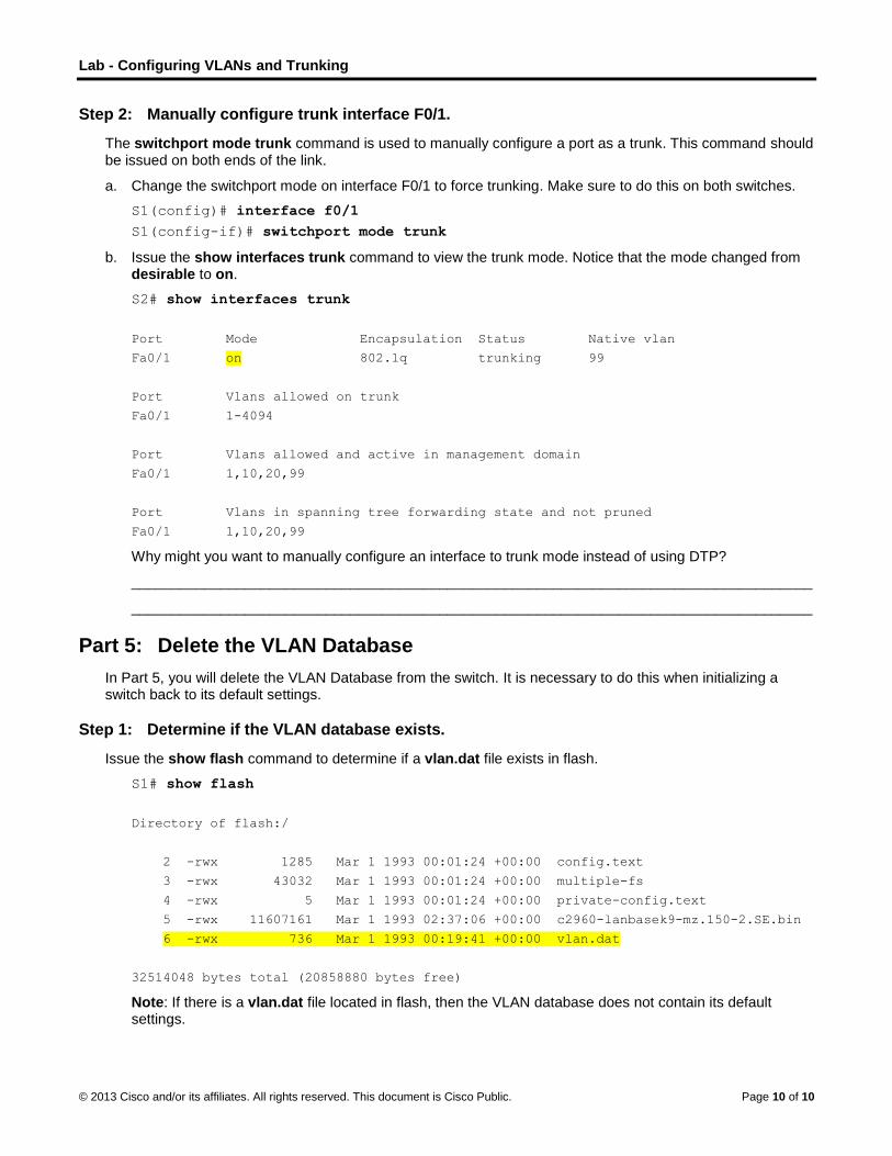
Step 2: Manually configure trunk interface F0/1.
The switchport mode trunk command is used to manually configure a port as a trunk. This command should be issued on both ends of the link.
a. Change the switchport mode on interface F0/1 to force trunking. Make sure to do this on both switches.
S1(config)# interface f0/1
S1(config-if)# switchport mode trunk
b. Issue the show interfaces trunk command to view the trunk mode. Notice that the mode changed from desirable to on.
S2# show interfaces trunk
Port Mode Encapsulation Status Native vlan
Fa0/1 on 802.1q trunking 99
Port Vlans allowed on trunk
Fa0/1 1-4094
Port Vlans allowed and active in management domain
Fa0/1 1,10,20,99
Port Vlans in spanning tree forwarding state and not pruned
Fa0/1 1,10,20,99
Why might you want to manually configure an interface to trunk mode instead of using DTP?
____________________________________________________________________________________
____________________________________________________________________________________
Part 5: Delete the VLAN Database
In Part 5, you will delete the VLAN Database from the switch. It is necessary to do this when initializing a switch back to its default settings.
Step 1: Determine if the VLAN database exists.
Issue the show flash command to determine if a vlan.dat file exists in flash.
S1# show flash
Directory of flash:/
2 -rwx 1285 Mar 1 1993 00:01:24 +00:00 config.text
3 -rwx 43032 Mar 1 1993 00:01:24 +00:00 multiple-fs
4 -rwx 5 Mar 1 1993 00:01:24 +00:00 private-config.text
5 -rwx 11607161 Mar 1 1993 02:37:06 +00:00 c2960-lanbasek9-mz.150-2.SE.bin
6 -rwx 736 Mar 1 1993 00:19:41 +00:00 vlan.dat
32514048 bytes total (20858880 bytes free)
Note: If there is a vlan.dat file located in flash, then the VLAN database does not contain its default settings.
Lab - Configuring VLANs and Trunking
© 2013 Cisco and/or its affiliates. All rights reserved. This document is Cisco Public. Page 11 of 11
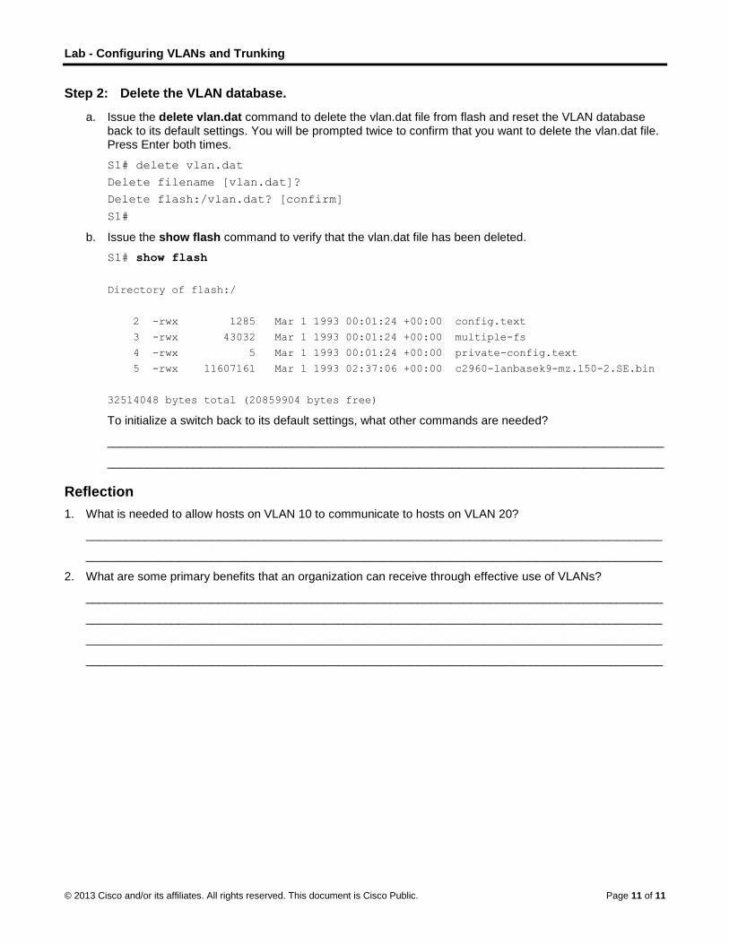
Step 2: Delete the VLAN database.
a. Issue the delete vlan.dat command to delete the vlan.dat file from flash and reset the VLAN database back to its default settings. You will be prompted twice to confirm that you want to delete the vlan.dat file. Press Enter both times.
S1# delete vlan.dat
Delete filename [vlan.dat]?
Delete flash:/vlan.dat? [confirm]
S1#
b. Issue the show flash command to verify that the vlan.dat file has been deleted.
S1# show flash
Directory of flash:/
2 -rwx 1285 Mar 1 1993 00:01:24 +00:00 config.text
3 -rwx 43032 Mar 1 1993 00:01:24 +00:00 multiple-fs
4 -rwx 5 Mar 1 1993 00:01:24 +00:00 private-config.text
5 -rwx 11607161 Mar 1 1993 02:37:06 +00:00 c2960-lanbasek9-mz.150-2.SE.bin
32514048 bytes total (20859904 bytes free)
To initialize a switch back to its default settings, what other commands are needed?
____________________________________________________________________________________
____________________________________________________________________________________
Reflection
1. What is needed to allow hosts on VLAN 10 to communicate to hosts on VLAN 20?
_______________________________________________________________________________________
_______________________________________________________________________________________
2. What are some primary benefits that an organization can receive through effective use of VLANs?
_______________________________________________________________________________________
_______________________________________________________________________________________
_______________________________________________________________________________________
_______________________________________________________________________________________
© 2013 Cisco and/or its affiliates. All rights reserved. This document is Cisco Public. Page 1 of 7
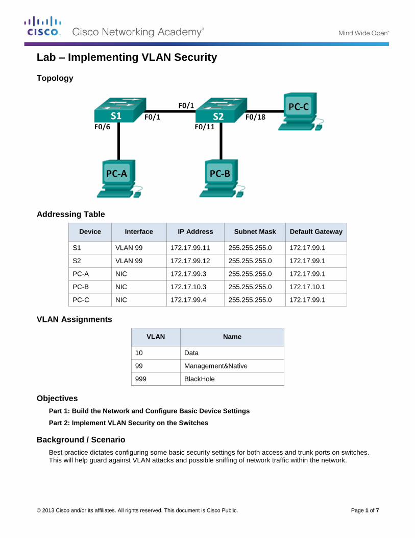
Lab – Implementing VLAN Security
Topology
Addressing Table
Device Interface IP Address Subnet Mask Default Gateway
S1 VLAN 99 172.17.99.11 255.255.255.0 172.17.99.1
S2 VLAN 99 172.17.99.12 255.255.255.0 172.17.99.1
PC-A NIC 172.17.99.3 255.255.255.0 172.17.99.1
PC-B NIC 172.17.10.3 255.255.255.0 172.17.10.1
PC-C NIC 172.17.99.4 255.255.255.0 172.17.99.1
VLAN Assignments
VLAN Name
10 Data
99 Management&Native
999 BlackHole
Objectives
Part 1: Build the Network and Configure Basic Device Settings
Part 2: Implement VLAN Security on the Switches
Background / Scenario
Best practice dictates configuring some basic security settings for both access and trunk ports on switches. This will help guard against VLAN attacks and possible sniffing of network traffic within the network.

Lab – Implementing VLAN Security
© 2013 Cisco and/or its affiliates. All rights reserved. This document is Cisco Public. Page 2 of 7
In this lab, you will configure the network devices in the topology with some basic settings, verify connectivity and then apply more stringent security measures on the switches. You will examine how Cisco switches behave by using various show commands. You will then apply security measures.
Note: The switches used with this lab are Cisco Catalyst 2960s with Cisco IOS Release 15.0(2) (lanbasek9 image). Other switches and Cisco IOS versions can be used. Depending on the model and Cisco IOS version, the commands available and output produced might vary from what is shown in the labs.
Note: Make sure that the switches have been erased and have no startup configurations. If you are unsure, contact your instructor.
Required Resources
2 Switches (Cisco 2960 with Cisco IOS Release 15.0(2) lanbasek9 image or comparable)
3 PCs (Windows 7, Vista, or XP with terminal emulation program, such as Tera Term)
Console cables to configure the Cisco IOS devices via the console ports
Ethernet cables as shown in the topology
Part 1: Build the Network and Configure Basic Device Settings
In Part 1, you will configure basic settings on the switches and PCs. Refer to the Addressing Table for device names and address information.
Step 1: Cable the network as shown in the topology.
Step 2: Initialize and reload the switches.
Step 3: Configure IP addresses on PC-A, PC-B, and PC-C.
Refer to the Addressing Table for PC address information.
Step 4: Configure basic settings for each switch.
a. Disable DNS lookup.
b. Configure the device names as shown in the topology.
c. Assign class as the privileged EXEC mode password.
d. Assign cisco as the console and VTY password and enable login for console and vty lines.
e. Configure synchronous logging for console and vty lines.
Step 5: Configure VLANs on each switch.
a. Create and name VLANs according to the VLAN Assignments table.
b. Configure the IP address listed in the Addressing Table for VLAN 99 on both switches.
c. Configure F0/6 on S1 as an access port and assign it to VLAN 99.
d. Configure F0/11 on S2 as an access port and assign it to VLAN 10.
e. Configure F0/18 on S2 as an access port and assign it to VLAN 99.
f. Issue show vlan brief command to verify VLAN and port assignments.
To which VLAN would an unassigned port, such as F0/8 on S2, belong?
____________________________________________________________________________________
Lab – Implementing VLAN Security
© 2013 Cisco and/or its affiliates. All rights reserved. This document is Cisco Public. Page 3 of 7
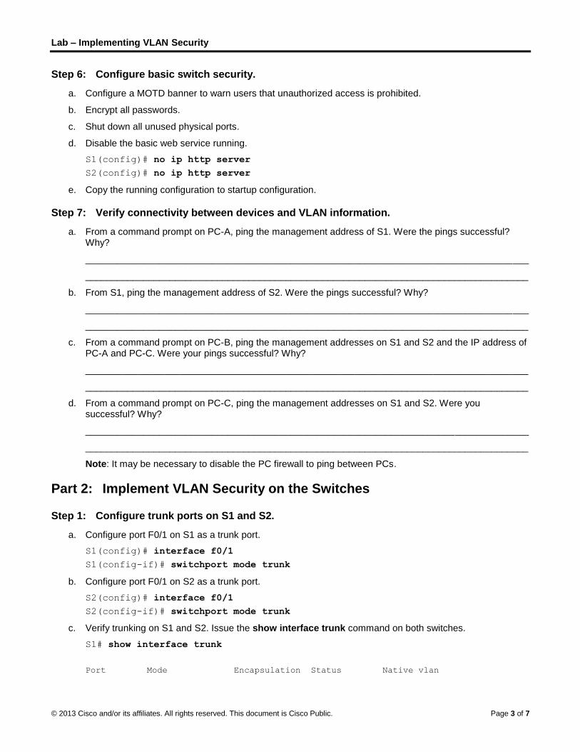
Step 6: Configure basic switch security.
a. Configure a MOTD banner to warn users that unauthorized access is prohibited.
b. Encrypt all passwords.
c. Shut down all unused physical ports.
d. Disable the basic web service running.
S1(config)# no ip http server
S2(config)# no ip http server
e. Copy the running configuration to startup configuration.
Step 7: Verify connectivity between devices and VLAN information.
a. From a command prompt on PC-A, ping the management address of S1. Were the pings successful? Why?
____________________________________________________________________________________
____________________________________________________________________________________
b. From S1, ping the management address of S2. Were the pings successful? Why?
____________________________________________________________________________________
____________________________________________________________________________________
c. From a command prompt on PC-B, ping the management addresses on S1 and S2 and the IP address of PC-A and PC-C. Were your pings successful? Why?
____________________________________________________________________________________
____________________________________________________________________________________
d. From a command prompt on PC-C, ping the management addresses on S1 and S2. Were you successful? Why?
____________________________________________________________________________________
____________________________________________________________________________________
Note: It may be necessary to disable the PC firewall to ping between PCs.
Part 2: Implement VLAN Security on the Switches
Step 1: Configure trunk ports on S1 and S2.
a. Configure port F0/1 on S1 as a trunk port.
S1(config)# interface f0/1
S1(config-if)# switchport mode trunk
b. Configure port F0/1 on S2 as a trunk port.
S2(config)# interface f0/1
S2(config-if)# switchport mode trunk
c. Verify trunking on S1 and S2. Issue the show interface trunk command on both switches.
S1# show interface trunk
Port Mode Encapsulation Status Native vlan

Lab – Implementing VLAN Security
© 2013 Cisco and/or its affiliates. All rights reserved. This document is Cisco Public. Page 4 of 7
Fa0/1 on 802.1q trunking 1
Port Vlans allowed on trunk
Fa0/1 1-4094
Port Vlans allowed and active in management domain
Fa0/1 1,10,99,999
Port Vlans in spanning tree forwarding state and not pruned
Fa0/1 1,10,99,999
Step 2: Change the native VLAN for the trunk ports on S1 and S2.
Changing the native VLAN for trunk ports from VLAN 1 to another VLAN is a good practice for security.
a. What is the current native VLAN for the S1 and S2 F0/1 interfaces?
____________________________________________________________________________________
b. Configure the native VLAN on the S1 F0/1 trunk interface to Management&Native VLAN 99.
S1# config t
S1(config)# interface f0/1
S1(config-if)# switchport trunk native vlan 99
c. Wait a few seconds. You should start receiving error messages on the console session of S1. What does the %CDP-4-NATIVE_VLAN_MISMATCH: message mean?
____________________________________________________________________________________
d. Configure the native VLAN on the S2 F0/1 trunk interface to VLAN 99.
S2(config)# interface f0/1
S2(config-if)# switchport trunk native vlan 99
e. Verify that the native VLAN is now 99 on both switches. S1 output is shown below.
S1# show interface trunk
Port Mode Encapsulation Status Native vlan
Fa0/1 on 802.1q trunking 99
Port Vlans allowed on trunk
Fa0/1 1-4094
Port Vlans allowed and active in management domain
Fa0/1 1,10,99,999
Port Vlans in spanning tree forwarding state and not pruned
Fa0/1 10,999
Step 3: Verify that traffic can successfully cross the trunk link.
a. From a command prompt on PC-A, ping the management address of S1. Were the pings successful? Why?
____________________________________________________________________________________

Lab – Implementing VLAN Security
© 2013 Cisco and/or its affiliates. All rights reserved. This document is Cisco Public. Page 5 of 7
b. From the console session on S1, ping the management address of S2. Were the pings successful? Why?
____________________________________________________________________________________
c. From a command prompt on PC-B, ping the management addresses on S1 and S2 and the IP address of PC-A and PC-C. Were your pings successful? Why?
____________________________________________________________________________________
d. From a command prompt on PC-C, ping the management addresses on S1 and S2 and the IP address of PC-A. Were you successful? Why?
____________________________________________________________________________________
Step 4: Prevent the use of DTP on S1 and S2.
Cisco uses a proprietary protocol known as the Dynamic Trunking Protocol (DTP) on its switches. Some ports automatically negotiate to trunking. A good practice is to turn off negotiation. You can see this default behavior by issuing the following command:
S1# show interface f0/1 switchport
Name: Fa0/1
Switchport: Enabled
Administrative Mode: trunk
Operational Mode: trunk
Administrative Trunking Encapsulation: dot1q
Operational Trunking Encapsulation: dot1q
Negotiation of Trunking: On
<Output Omitted>
a. Turn off negotiation on S1.
S1(config)# interface f0/1
S1(config-if)# switchport nonegotiate
b. Turn off negotiation on S2.
S2(config)# interface f0/1
S2(config-if)# switchport nonegotiate
c. Verify that negotiation is off by issuing the show interface f0/1 switchport command on S1 and S2.
S1# show interface f0/1 switchport
Name: Fa0/1
Switchport: Enabled
Administrative Mode: trunk
Operational Mode: trunk
Administrative Trunking Encapsulation: dot1q
Operational Trunking Encapsulation: dot1q
Negotiation of Trunking: Off
<Output Omitted>
Step 5: Secure access ports on S1 and S2.
Even though you shut down unused ports on the switches, if a device is connected to one of those ports and the interface is enabled, trunking could occur. In addition, all ports by default are in VLAN 1. A good practice is to put all unused ports in a “black hole” VLAN. In this step, you will disable trunking on all unused ports. You will also assign unused ports to VLAN 999. For the purposes of this lab, only ports 2 through 5 will be configured on both switches.

Lab – Implementing VLAN Security
© 2013 Cisco and/or its affiliates. All rights reserved. This document is Cisco Public. Page 6 of 7
a. Issue the show interface f0/2 switchport command on S1. Notice the administrative mode and state for trunking negotiation.
S1# show interface f0/2 switchport
Name: Fa0/2
Switchport: Enabled
Administrative Mode: dynamic auto
Operational Mode: down
Administrative Trunking Encapsulation: dot1q
Negotiation of Trunking: On
<Output Omitted>
b. Disable trunking on S1 access ports.
S1(config)# interface range f0/2 – 5
S1(config-if-range)# switchport mode access
S1(config-if-range)# switchport access vlan 999
c. Disable trunking on S2 access ports.
d. Verify that port F0/2 is set to access on S1.
S1# show interface f0/2 switchport
Name: Fa0/2
Switchport: Enabled
Administrative Mode: static access
Operational Mode: down
Administrative Trunking Encapsulation: dot1q
Negotiation of Trunking: Off
Access Mode VLAN: 999 (BlackHole)
Trunking Native Mode VLAN: 1 (default)
Administrative Native VLAN tagging: enabled
Voice VLAN: none
<Output Omitted>
e. Verify that VLAN port assignments on both switches are correct. S1 is shown below as an example.
S1# show vlan brief
VLAN Name Status Ports
---- ------------------------------ --------- ------------------------------
1 default active Fa0/7, Fa0/8, Fa0/9, Fa0/10
Fa0/11, Fa0/12, Fa0/13, Fa0/14
Fa0/15, Fa0/16, Fa0/17, Fa0/18
Fa0/19, Fa0/20, Fa0/21, Fa0/22
Fa0/23, Fa0/24, Gi0/1, Gi0/2
10 Data active
99 Management&Native active Fa0/6
999 BlackHole active Fa0/2, Fa0/3, Fa0/4, Fa0/5
1002 fddi-default act/unsup
1003 token-ring-default act/unsup
1004 fddinet-default act/unsup
1005 trnet-default act/unsup
Restrict VLANs allowed on trunk ports.

Lab – Implementing VLAN Security
© 2013 Cisco and/or its affiliates. All rights reserved. This document is Cisco Public. Page 7 of 7
By default, all VLANs are allowed to be carried on trunk ports. For security reasons, it is a good practice to only allow specific desired VLANs to cross trunk links on your network.
f. Restrict the trunk port F0/1 on S1 to only allow VLANs 10 and 99.
S1(config)# interface f0/1
S1(config-if)# switchport trunk allowed vlan 10,99
g. Restrict the trunk port F0/1 on S2 to only allow VLANs 10 and 99.
h. Verify the allowed VLANs. Issue a show interface trunk command in privileged EXEC mode on both S1 and S2.
S1# show interface trunk
Port Mode Encapsulation Status Native vlan
Fa0/1 on 802.1q trunking 99
Port Vlans allowed on trunk
Fa0/1 10,99
Port Vlans allowed and active in management domain
Fa0/1 10,99
Port Vlans in spanning tree forwarding state and not pruned
Fa0/1 10,99
What is the result?
____________________________________________________________________________________
Reflection
What, if any, are the security problems with the default configuration of a Cisco switch?
_______________________________________________________________________________________
_______________________________________________________________________________________
_______________________________________________________________________________________
_______________________________________________________________________________________

© 2013 Cisco and/or its affiliates. All rights reserved. This document is Cisco Public. Page 1 of 7
Lab – Configuring Basic Router Settings with IOS CLI
Topology
Addressing Table
Device Interface IP Address Subnet Mask Default Gateway
R1 G0/0 192.168.0.1 255.255.255.0 N/A
G0/1 192.168.1.1 255.255.255.0 N/A
PC-A NIC 192.168.1.3 255.255.255.0 192.168.1.1
PC-B NIC 192.168.0.3 255.255.255.0 192.168.0.1
Objectives
Part 1: Set Up the Topology and Initialize Devices
Cable equipment to match the network topology.
Initialize and restart the router and switch.
Part 2: Configure Devices and Verify Connectivity
Assign static IPv4 information to the PC interfaces.
Configure basic router settings.
Verify network connectivity.
Configure the router for SSH.
Part 3: Display Router Information
Retrieve hardware and software information from the router.
Interpret the output from the startup configuration.
Interpret the output from the routing table.
Verify the status of the interfaces.
Part 4: Configure IPv6 and Verify Connectivity
Background / Scenario
This is a comprehensive lab to review previously covered IOS router commands. In Parts 1 and 2, you will cable the equipment and complete basic configurations and IPv4 interface settings on the router.
In Part 3, you will use SSH to connect to the router remotely and utilize IOS commands to retrieve information from the device to answer questions about the router. In Part 4, you will configure IPv6 on the router so that PC-B can acquire an IP address and then verify connectivity.
Lab – Configuring Basic Router Settings with IOS CLI
© 2013 Cisco and/or its affiliates. All rights reserved. This document is Cisco Public. Page 2 of 7
For review purposes, this lab provides the commands necessary for specific router configurations.
Note: The routers used with CCNA hands-on labs are Cisco 1941 Integrated Services Routers (ISRs) with Cisco IOS Release 15.2(4)M3 (universalk9 image). The switches used are Cisco Catalyst 2960 with Cisco IOS Release 15.0(2) (lanbasek9 image). Other routers, switches, and Cisco IOS versions can be used. Depending on the model and Cisco IOS version, the commands available and output produced might vary from what is shown in the labs. Refer to the Router Interface Summary Table at the end of this lab for the correct interface identifiers.
Note: Make sure that the router and switch have been erased and have no startup configurations. Refer to Appendix A for the procedures to initialize and reload devices.
Required Resources
1 Router (Cisco 1941 with Cisco IOS Release 15.2(4)M3 universal image or comparable)
1 Switch (Cisco 2960 with Cisco IOS Release 15.0(2) lanbasek9 image or comparable)
2 PCs (Windows 7, Vista, or XP with terminal emulation program, such as Tera Term)
Console cables to configure the Cisco IOS devices via the console ports
Ethernet cables as shown in the topology
Note: The Gigabit Ethernet interfaces on Cisco 1941 ISRs are autosensing and an Ethernet straight-through cable can be used between the router and PC-B. If using another model Cisco router, it may be necessary to use an Ethernet crossover cable.
Part 1: Set Up the Topology and Initialize Devices
Step 1: Cable the network as shown in the topology.
a. Attach the devices as shown in the topology diagram, and cable as necessary.
b. Power on all the devices in the topology.
Step 2: Initialize and reload the router and switch.
Note: Appendix A details the steps to initialize and reload the devices.
Part 2: Configure Devices and Verify Connectivity
Step 1: Configure the PC interfaces.
a. Configure the IP address, subnet mask, and default gateway settings on PC-A.
b. Configure the IP address, subnet mask, and default gateway settings on PC-B.
Step 2: Configure the router.
a. Console into the router and enable privileged EXEC mode.
Router> enable
Router#
b. Enter into global configuration mode.
Router# config terminal
Router(config)#
c. Assign a device name to the router.
Lab – Configuring Basic Router Settings with IOS CLI
© 2013 Cisco and/or its affiliates. All rights reserved. This document is Cisco Public. Page 3 of 7
Router(config)# hostname R1
d. Disable DNS lookup to prevent the router from attempting to translate incorrectly entered commands as though they were hostnames.
R1(config)# no ip domain-lookup
e. Require that a minimum of 10 characters be used for all passwords.
R1(config)# security passwords min-length 10
Besides setting a minimum length, list other ways to strengthen passwords.
____________________________________________________________________________________
f. Assign cisco12345 as the privileged EXEC encrypted password.
R1(config)# enable secret cisco12345
g. Assign ciscoconpass as the console password, establish a timeout, enable login, and add the logging synchronous command. The logging synchronous command synchronizes debug and Cisco IOS software output and prevents these messages from interrupting your keyboard input.
R1(config)# line con 0
R1(config-line)# password ciscoconpass
R1(config-line)# exec-timeout 5 0
R1(config-line)# login
R1(config-line)# logging synchronous
R1(config-line)# exit
R1(config)#
For the exec-timeout command, what do the 5 and 0 represent?
____________________________________________________________________________________
h. Assign ciscovtypass as the vty password, establish a timeout, enable login, and add the logging synchronous command.
R1(config)# line vty 0 4
R1(config-line)# password ciscovtypass
R1(config-line)# exec-timeout 5 0
R1(config-line)# login
R1(config-line)# logging synchronous
R1(config-line)# exit
R1(config)#
i. Encrypt the clear text passwords.
R1(config)# service password-encryption
j. Create a banner that warns anyone accessing the device that unauthorized access is prohibited.
R1(config)# banner motd #Unauthorized access prohibited!#
k. Configure an IP address and interface description. Activate both interfaces on the router.
R1(config)# int g0/0
R1(config-if)# description Connection to PC-B
R1(config-if)# ip address 192.168.0.1 255.255.255.0
R1(config-if)# no shutdown
R1(config-if)# int g0/1

Lab – Configuring Basic Router Settings with IOS CLI
© 2013 Cisco and/or its affiliates. All rights reserved. This document is Cisco Public. Page 4 of 7
R1(config-if)# description Connection to S1
R1(config-if)# ip address 192.168.1.1 255.255.255.0
R1(config-if)# no shutdown
R1(config-if)# exit
R1(config)# exit
R1#
l. Set the clock on the router; for example:
R1# clock set 17:00:00 18 Feb 2013
m. Save the running configuration to the startup configuration file.
R1# copy running-config startup-config
Destination filename [startup-config]?
Building configuration...
[OK]
R1#
What would be the result of reloading the router prior to completing the copy running-config startup-config command?
____________________________________________________________________________________
____________________________________________________________________________________
Step 3: Verify network connectivity.
a. Ping PC-B from a command prompt on PC-A.
Note: It may be necessary to disable the PCs firewall.
Were the pings successful? __________
After completing this series of commands, what type of remote access could be used to access R1?
____________________________________________________________________________________
b. Remotely access R1 from PC-A using the Tera Term Telnet client.
Open Tera Term and enter the G0/1 interface IP address of R1 in the Host: field of the Tera Term: New Connection window. Ensure that the Telnet radio button is selected and then click OK to connect to the router.

Lab – Configuring Basic Router Settings with IOS CLI
© 2013 Cisco and/or its affiliates. All rights reserved. This document is Cisco Public. Page 5 of 7
Was remote access successful? __________
Why is the Telnet protocol considered to be a security risk?
____________________________________________________________________________________
____________________________________________________________________________________
Step 4: Configure the router for SSH access.
a. Enable SSH connections and create a user in the local database of the router.
R1# configure terminal
R1(config)# ip domain-name CCNA-lab.com
R1(config)# username admin privilege 15 secret adminpass1
R1(config)# line vty 0 4
R1(config-line)# transport input ssh
R1(config-line)# login local
R1(config-line)# exit
R1(config)# crypto key generate rsa modulus 1024
R1(config)# exit
b. Remotely access R1 from PC-A using the Tera Term SSH client.
Open Tera Term and enter the G0/1 interface IP address of R1 in the Host: field of the Tera Term: New Connection window. Ensure that the SSH radio button is selected and then click OK to connect to the router.
Was remote access successful? __________
Part 3: Display Router Information
In Part 3, you will use show commands from an SSH session to retrieve information from the router.
Step 1: Establish an SSH session to R1.
Using Tera Term on PC-B, open an SSH session to R1 at IP address 192.168.0.1 and log in as admin with the password adminpass1.
Lab – Configuring Basic Router Settings with IOS CLI
© 2013 Cisco and/or its affiliates. All rights reserved. This document is Cisco Public. Page 6 of 7
Step 2: Retrieve important hardware and software information.
a. Use the show version command to answer questions about the router.
What is the name of the IOS image that the router is running?
____________________________________________________________________________________
How much non-volatile random-access memory (NVRAM) does the router have?
____________________________________________________________________________________
How much Flash memory does the router have?
____________________________________________________________________________________
b. The show commands often provide multiple screens of outputs. Filtering the output allows a user to display certain sections of the output. To enable the filtering command, enter a pipe (|) character after a show command, followed by a filtering parameter and a filtering expression. You can match the output to the filtering statement by using the include keyword to display all lines from the output that contain the filtering expression. Filter the show version command, using show version | include register to answer the following question.
What is the boot process for the router on the next reload?
____________________________________________________________________________________
____________________________________________________________________________________
____________________________________________________________________________________
Step 3: Display the startup configuration.
Use the show startup-config command on the router to answer the following questions.
How are passwords presented in the output?
____________________________________________________________________________________
____________________________________________________________________________________
____________________________________________________________________________________
Use the show startup-config | begin vty command.
What is the result of using this command?
____________________________________________________________________________________
____________________________________________________________________________________
Step 4: Display the routing table on the router.
Use the show ip route command on the router to answer the following questions.
What code is used in the routing table to indicate a directly connected network?
_______________________________________________________________________________________
How many route entries are coded with a C code in the routing table? __________
Step 5: Display a summary list of the interfaces on the router.
Use the show ip interface brief command on the router to answer the following question.
What command changed the status of the Gigabit Ethernet ports from administratively down to up?
____________________________________________________________________________________

Lab – Configuring Basic Router Settings with IOS CLI
© 2013 Cisco and/or its affiliates. All rights reserved. This document is Cisco Public. Page 7 of 7
Part 4: Configure IPv6 and Verify Connectivity
Step 1: Assign IPv6 addresses to R1 G0/0 and enable IPv6 routing.
Note: Assigning an IPv6 address in addition to an IPv4 address on an interface is known as dual stacking, because both the IPv4 and IPv6 protocol stacks are active. By enabling IPv6 unicast routing on R1, PC-B receives the R1 G0/0 IPv6 network prefix and can autoconfigure its IPv6 address and its default gateway.
a. Assign an IPv6 global unicast address to interface G0/0, assign the link-local address in addition to the unicast address on the interface, and enable IPv6 routing.
R1# configure terminal
R1(config)# interface g0/0
R1(config-if)# ipv6 address 2001:db8:acad:a::1/64
R1(config-if)# ipv6 address fe80::1 link-local
R1(config-if)# no shutdown
R1(config-if)# exit
R1(config)# ipv6 unicast-routing
R1(config)# exit
b. Use the show ipv6 int brief command to verify IPv6 settings on R1.
If no IPv6 address is assigned to G0/1, why is it listed as [up/up]?
____________________________________________________________________________________
____________________________________________________________________________________
c. Issue the ipconfig command on PC-B to examine the IPv6 configuration.
What is the IPv6 address assigned to PC-B?
____________________________________________________________________________________
What is the default gateway assigned to PC-B? ____________________
Issue a ping from PC-B to the R1 default gateway link local address. Was it successful? __________
Issue a ping from PC-B to the R1 IPv6 unicast address 2001:db8:acad:a::1. Was it successful? ________
Reflection
1. In researching a network connectivity issue, a technician suspects that an interface was not enabled. What show command could the technician use to troubleshoot this issue?
_______________________________________________________________________________________
2. In researching a network connectivity issue, a technician suspects that an interface was assigned an incorrect subnet mask. What show command could the technician use to troubleshoot this issue?
_______________________________________________________________________________________
3. After configuring IPv6 on the R1 G0/0 PC-B LAN, if you were to ping from PC-A to the PC-B IPv6 address, would the ping succeed? Why or why not?
_______________________________________________________________________________________
_______________________________________________________________________________________
© 2013 Cisco and/or its affiliates. All rights reserved. This document is Cisco Public. Page 1 of 5
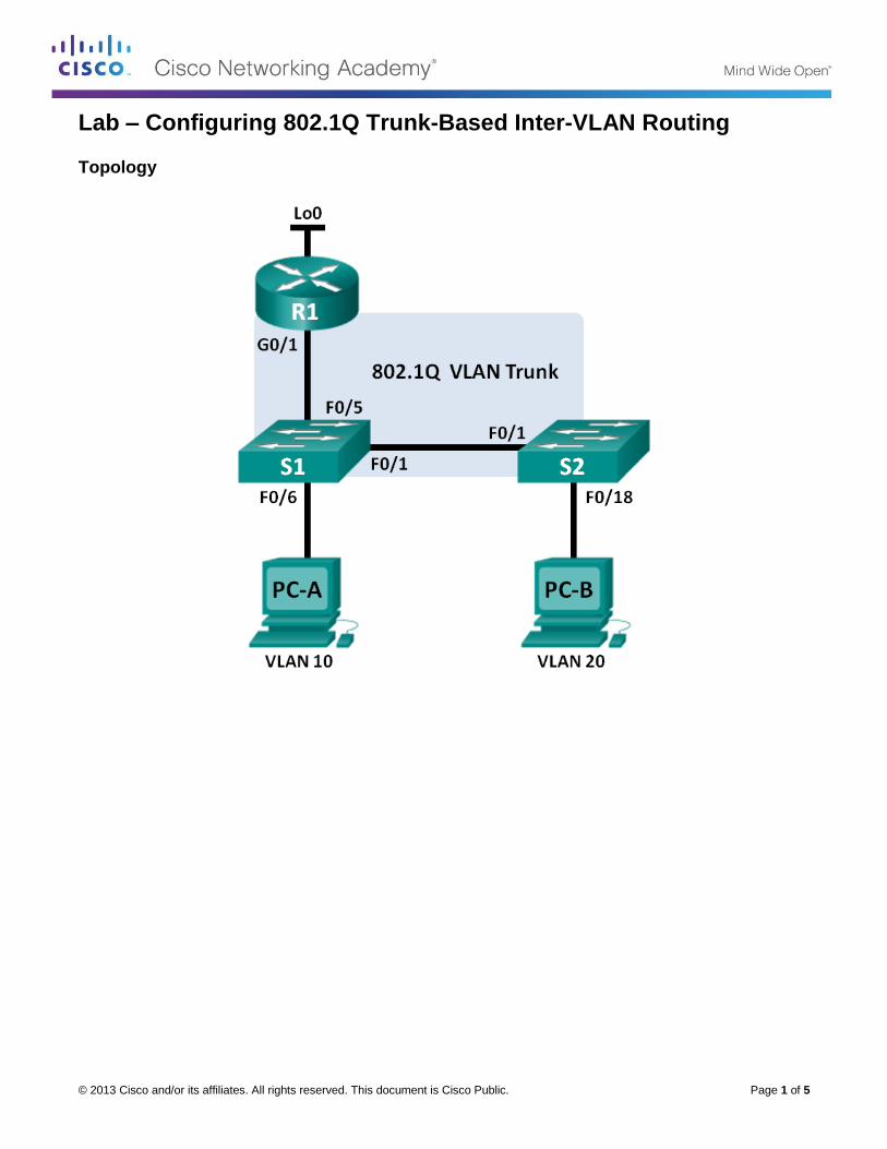
Lab – Configuring 802.1Q Trunk-Based Inter-VLAN Routing
Topology
Lab – Configuring 802.1Q Trunk-Based Inter-VLAN Routing
© 2013 Cisco and/or its affiliates. All rights reserved. This document is Cisco Public. Page 2 of 5
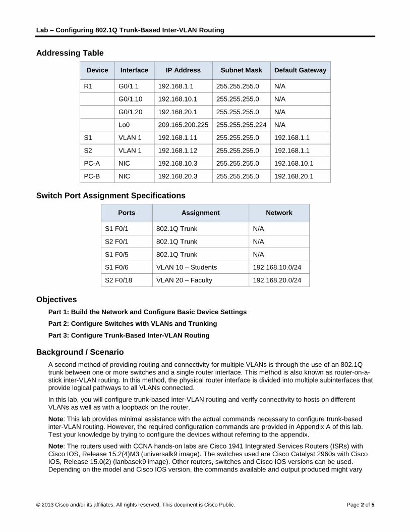
Addressing Table
Device Interface IP Address Subnet Mask Default Gateway
R1 G0/1.1 192.168.1.1 255.255.255.0 N/A
G0/1.10 192.168.10.1 255.255.255.0 N/A
G0/1.20 192.168.20.1 255.255.255.0 N/A
Lo0 209.165.200.225 255.255.255.224 N/A
S1 VLAN 1 192.168.1.11 255.255.255.0 192.168.1.1
S2 VLAN 1 192.168.1.12 255.255.255.0 192.168.1.1
PC-A NIC 192.168.10.3 255.255.255.0 192.168.10.1
PC-B NIC 192.168.20.3 255.255.255.0 192.168.20.1
Switch Port Assignment Specifications
Ports Assignment Network
S1 F0/1 802.1Q Trunk N/A
S2 F0/1 802.1Q Trunk N/A
S1 F0/5 802.1Q Trunk N/A
S1 F0/6 VLAN 10 – Students 192.168.10.0/24
S2 F0/18 VLAN 20 – Faculty 192.168.20.0/24
Objectives
Part 1: Build the Network and Configure Basic Device Settings
Part 2: Configure Switches with VLANs and Trunking
Part 3: Configure Trunk-Based Inter-VLAN Routing
Background / Scenario
A second method of providing routing and connectivity for multiple VLANs is through the use of an 802.1Q trunk between one or more switches and a single router interface. This method is also known as router-on-a-stick inter-VLAN routing. In this method, the physical router interface is divided into multiple subinterfaces that provide logical pathways to all VLANs connected.
In this lab, you will configure trunk-based inter-VLAN routing and verify connectivity to hosts on different VLANs as well as with a loopback on the router.
Note: This lab provides minimal assistance with the actual commands necessary to configure trunk-based inter-VLAN routing. However, the required configuration commands are provided in Appendix A of this lab. Test your knowledge by trying to configure the devices without referring to the appendix.
Note: The routers used with CCNA hands-on labs are Cisco 1941 Integrated Services Routers (ISRs) with Cisco IOS, Release 15.2(4)M3 (universalk9 image). The switches used are Cisco Catalyst 2960s with Cisco IOS, Release 15.0(2) (lanbasek9 image). Other routers, switches and Cisco IOS versions can be used. Depending on the model and Cisco IOS version, the commands available and output produced might vary
Lab – Configuring 802.1Q Trunk-Based Inter-VLAN Routing
© 2013 Cisco and/or its affiliates. All rights reserved. This document is Cisco Public. Page 3 of 5
from what is shown in the labs. Refer to the Router Interface Summary Table at the end of the lab for the correct interface identifiers.
Note: Make sure that the routers and switches have been erased and have no startup configurations. If you are unsure, contact your instructor.
Required Resources
1 Router (Cisco 1941 with Cisco IOS, release 15.2(4)M3 universal image or comparable)
2 Switches (Cisco 2960 with Cisco IOS, release 15.0(2) lanbasek9 image or comparable)
2 PCs (Windows 7, Vista, or XP with terminal emulation program, such as Tera Term)
Console cables to configure the Cisco IOS devices via the console ports
Ethernet cables as shown in the topology
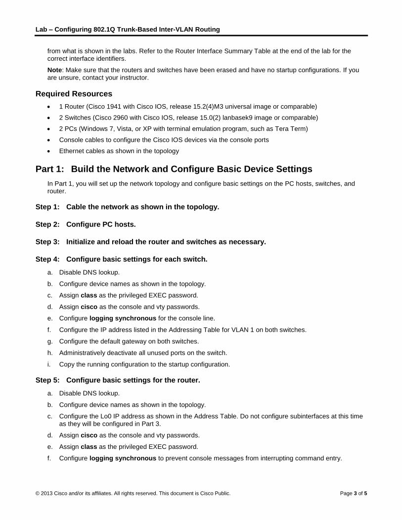
Part 1: Build the Network and Configure Basic Device Settings
In Part 1, you will set up the network topology and configure basic settings on the PC hosts, switches, and router.
Step 1: Cable the network as shown in the topology.
Step 2: Configure PC hosts.
Step 3: Initialize and reload the router and switches as necessary.
Step 4: Configure basic settings for each switch.
a. Disable DNS lookup.
b. Configure device names as shown in the topology.
c. Assign class as the privileged EXEC password.
d. Assign cisco as the console and vty passwords.
e. Configure logging synchronous for the console line.
f. Configure the IP address listed in the Addressing Table for VLAN 1 on both switches.
g. Configure the default gateway on both switches.
h. Administratively deactivate all unused ports on the switch.
i. Copy the running configuration to the startup configuration.
Step 5: Configure basic settings for the router.
a. Disable DNS lookup.
b. Configure device names as shown in the topology.
c. Configure the Lo0 IP address as shown in the Address Table. Do not configure subinterfaces at this time as they will be configured in Part 3.
d. Assign cisco as the console and vty passwords.
e. Assign class as the privileged EXEC password.
f. Configure logging synchronous to prevent console messages from interrupting command entry.

Lab – Configuring 802.1Q Trunk-Based Inter-VLAN Routing
© 2013 Cisco and/or its affiliates. All rights reserved. This document is Cisco Public. Page 4 of 5
g. Copy the running configuration to the startup configuration.
Part 2: Configure Switches with VLANs and Trunking
In Part 2, you will configure the switches with VLANs and trunking.
Note: The required commands for Part 2 are provided in Appendix A. Test your knowledge by trying to configure S1 and S2 without referring to the appendix.
Step 1: Configure VLANs on S1.
a. On S1, configure the VLANs and names listed in the Switch Port Assignment Specifications table. Write the commands you used in the space provided.
____________________________________________________________________________________
____________________________________________________________________________________
____________________________________________________________________________________
____________________________________________________________________________________
____________________________________________________________________________________
b. On S1, configure the interface connected to R1 as a trunk. Also configure the interface connected to S2 as a trunk. Write the commands you used in the space provided.
____________________________________________________________________________________
____________________________________________________________________________________
____________________________________________________________________________________
____________________________________________________________________________________
c. On S1, assign the access port for PC-A to VLAN 10. Write the commands you used in the space provided.
____________________________________________________________________________________
____________________________________________________________________________________
____________________________________________________________________________________
Step 2: Configure VLANs on Switch 2.
a. On S2, configure the VLANs and names listed in the Switch Port Assignment Specifications table.
b. On S2, verify that the VLAN names and numbers match those on S1. Write the command you used in the space provided.
____________________________________________________________________________________
c. On S2, assign the access port for PC-B to VLAN 20.
d. On S2, configure the interface connected to S1 as a trunk.
Part 3: Configure Trunk-Based Inter-VLAN Routing
In Part 3, you will configure R1 to route to multiple VLANs by creating subinterfaces for each VLAN. This method of inter-VLAN routing is called router-on-a-stick.
Note: The required commands for Part 3 are provided in Appendix A. Test your knowledge by trying to configure trunk-based or router-on-a-stick inter-VLAN routing without referring to the appendix.

Lab – Configuring 802.1Q Trunk-Based Inter-VLAN Routing
© 2013 Cisco and/or its affiliates. All rights reserved. This document is Cisco Public. Page 5 of 5
Step 1: Configure a subinterface for VLAN 1.
a. Create a subinterface on R1 G0/1 for VLAN 1 using 1 as the subinterface ID. Write the command you used in the space provided.
____________________________________________________________________________________
b. Configure the subinterface to operate on VLAN 1. Write the command you used in the space provided.
____________________________________________________________________________________
c. Configure the subinterface with the IP address from the Address Table. Write the command you used in the space provided.
____________________________________________________________________________________
Step 2: Configure a subinterface for VLAN 10.
a. Create a subinterface on R1 G0/1 for VLAN 10 using 10 as the subinterface ID.
b. Configure the subinterface to operate on VLAN 10.
c. Configure the subinterface with the address from the Address Table.
Step 3: Configure a subinterface for VLAN 20.
a. Create a subinterface on R1 G0/1 for VLAN 20 using 20 as the subinterface ID.
b. Configure the subinterface to operate on VLAN 20.
c. Configure the subinterface with the address from the Address Table.
Step 4: Enable the G0/1 interface.
Enable the G0/1 interface. Write the commands you used in the space provided.
_______________________________________________________________________________________
_______________________________________________________________________________________
Step 5: Verify connectivity.
Enter the command to view the routing table on R1. What networks are listed?
_______________________________________________________________________________________
From PC-A, is it possible to ping the default gateway for VLAN 10? _____________
From PC-A, is it possible to ping PC-B? _____________
From PC-A, is it possible to ping Lo0? _____________
From PC-A, is it possible to ping S2? _____________
If the answer is no to any of these questions, troubleshoot the configurations and correct any errors.
Reflection
What are the advantages of trunk-based or router-on-a-stick inter-VLAN routing?
_______________________________________________________________________________________
_______________________________________________________________________________________
_______________________________________________________________________________________
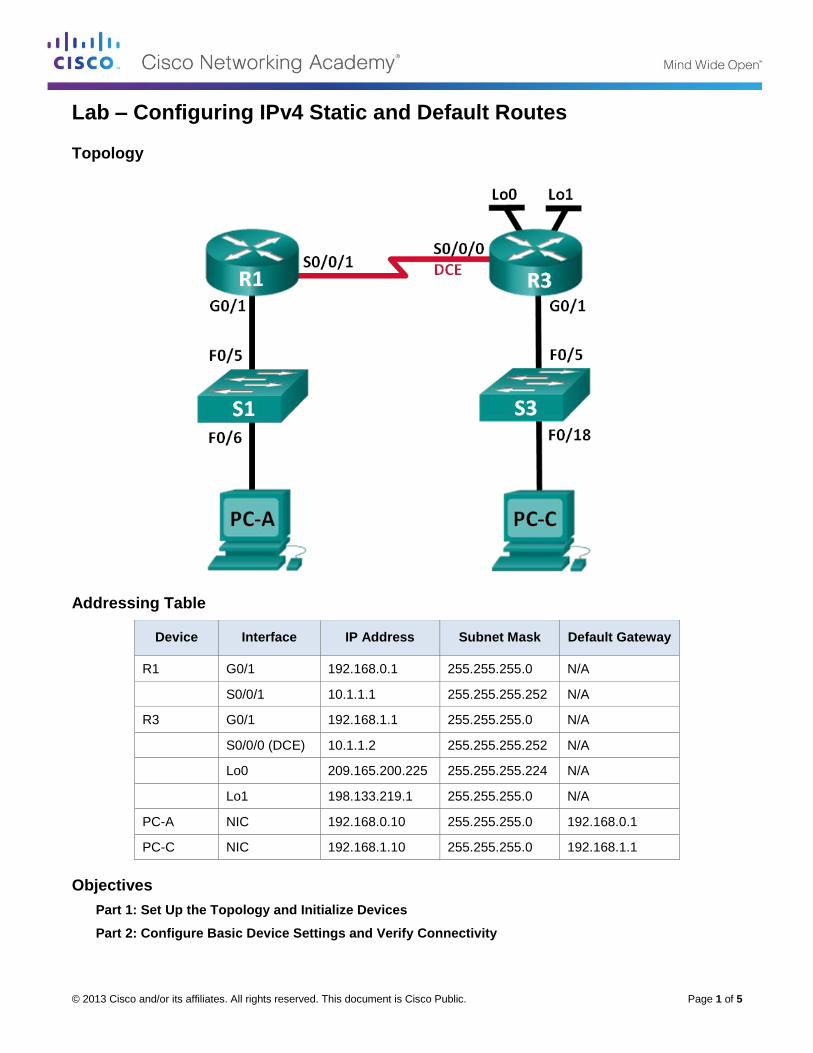
© 2013 Cisco and/or its affiliates. All rights reserved. This document is Cisco Public. Page 1 of 5
Lab – Configuring IPv4 Static and Default Routes
Topology
Addressing Table
Device Interface IP Address Subnet Mask Default Gateway
R1 G0/1 192.168.0.1 255.255.255.0 N/A
S0/0/1 10.1.1.1 255.255.255.252 N/A
R3 G0/1 192.168.1.1 255.255.255.0 N/A
S0/0/0 (DCE) 10.1.1.2 255.255.255.252 N/A
Lo0 209.165.200.225 255.255.255.224 N/A
Lo1 198.133.219.1 255.255.255.0 N/A
PC-A NIC 192.168.0.10 255.255.255.0 192.168.0.1
PC-C NIC 192.168.1.10 255.255.255.0 192.168.1.1
Objectives
Part 1: Set Up the Topology and Initialize Devices
Part 2: Configure Basic Device Settings and Verify Connectivity

Lab – Configuring IPv4 Static and Default Routes
© 2013 Cisco and/or its affiliates. All rights reserved. This document is Cisco Public. Page 2 of 5
Part 3: Configure Static Routes
Configure a recursive static route.
Configure a directly connected static route.
Configure and remove static routes.
Part 4: Configure and Verify a Default Route
Required Resources
2 Routers (Cisco 1941 with Cisco IOS Release 15.2(4)M3 universal image or comparable)
2 Switches (Cisco 2960 with Cisco IOS Release 15.0(2) lanbasek9 image or comparable)
2 PCs (Windows 7, Vista, or XP with terminal emulation program, such as Tera Term)
Console cables to configure the Cisco IOS devices via the console ports
Ethernet and serial cables as shown in the topology
Part 1: Set Up the Topology and Initialize Devices
Step 1: Cable the network as shown in the topology.
Step 2: Initialize and reload the router and switch.
Part 2: Configure Basic Device Settings and Verify Connectivity
In Part 2, you will configure basic settings, such as the interface IP addresses, device access, and passwords. You will verify LAN connectivity and identify routes listed in the routing tables for R1 and R3.
Step 1: Configure the PC interfaces.
Step 2: Configure basic settings on the routers.
a. Configure device names, as shown in the Topology and Addressing Table.
b. Disable DNS lookup.
c. Assign class as the enable password and assign cisco as the console and vty password.
d. Save the running configuration to the startup configuration file.
Step 3: Configure IP settings on the routers.
a. Configure the R1 and R3 interfaces with IP addresses according to the Addressing Table.
b. The S0/0/0 connection is the DCE connection and requires the clock rate command. The R3 S0/0/0 configuration is displayed below.
R3(config)# interface s0/0/0
R3(config-if)# ip address 10.1.1.2 255.255.255.252
R3(config-if)# clock rate 128000
R3(config-if)# no shutdown
Step 4: Verify connectivity of the LANs.
a. Test connectivity by pinging from each PC to the default gateway that has been configured for that host.

Lab – Configuring IPv4 Static and Default Routes
© 2013 Cisco and/or its affiliates. All rights reserved. This document is Cisco Public. Page 3 of 5
From PC-A, is it possible to ping the default gateway? __________
From PC-C, is it possible to ping the default gateway? __________
b. Test connectivity by pinging between the directly connected routers.
From R1, is it possible to ping the S0/0/0 interface of R3? __________
If the answer is no to any of these questions, troubleshoot the configurations and correct the error.
c. Test connectivity between devices that are not directly connected.
From PC-A, is it possible to ping PC-C? __________
From PC-A, is it possible to ping Lo0? __________
From PC-A, is it possible to ping Lo1? __________
Were these pings successful? Why or why not?
____________________________________________________________________________________
Note: It may be necessary to disable the PC firewall to ping between PCs.
Step 5: Gather information.
a. Check the status of the interfaces on R1 with the show ip interface brief command.
How many interfaces are activated on R1? __________
b. Check the status of the interfaces on R3.
How many interfaces are activated on R3? __________
c. View the routing table information for R1 using the show ip route command.
What networks are present in the Addressing Table of this lab, but not in the routing table for R1?
____________________________________________________________________________________
d. View the routing table information for R3.
What networks are present in the Addressing Table in this lab, but not in the routing table for R3?
____________________________________________________________________________________
Why are all the networks not in the routing tables for each of the routers?
____________________________________________________________________________________
____________________________________________________________________________________
Part 3: Configure Static Routes
In Part 3, you will employ multiple ways to implement static and default routes, you will confirm that the routes have been added to the routing tables of R1 and R3, and you will verify connectivity based on the introduced routes.
Note: This lab provides minimal assistance with the actual commands necessary to configure static routing. However, the required commands are provided in Appendix A. Test your knowledge by trying to configure the devices without referring to the appendix.
Step 1: Configure a recursive static route.
With a recursive static route, the next-hop IP address is specified. Because only the next-hop IP is specified, the router must perform multiple lookups in the routing table before forwarding packets. To configure recursive static routes, use the following syntax:
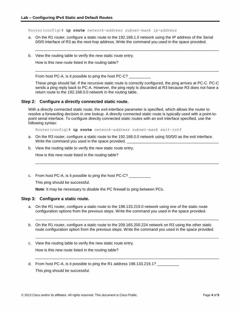
Lab – Configuring IPv4 Static and Default Routes
© 2013 Cisco and/or its affiliates. All rights reserved. This document is Cisco Public. Page 4 of 5
Router(config)# ip route network-address subnet-mask ip-address
a. On the R1 router, configure a static route to the 192.168.1.0 network using the IP address of the Serial 0/0/0 interface of R3 as the next-hop address. Write the command you used in the space provided.
____________________________________________________________________________________
b. View the routing table to verify the new static route entry.
How is this new route listed in the routing table?
____________________________________________________________________________________
From host PC-A, is it possible to ping the host PC-C? __________
These pings should fail. If the recursive static route is correctly configured, the ping arrives at PC-C. PC-C sends a ping reply back to PC-A. However, the ping reply is discarded at R3 because R3 does not have a return route to the 192.168.0.0 network in the routing table.
Step 2: Configure a directly connected static route.
With a directly connected static route, the exit-interface parameter is specified, which allows the router to resolve a forwarding decision in one lookup. A directly connected static route is typically used with a point-to-point serial interface. To configure directly connected static routes with an exit interface specified, use the following syntax:
Router(config)# ip route network-address subnet-mask exit-intf
a. On the R3 router, configure a static route to the 192.168.0.0 network using S0/0/0 as the exit interface. Write the command you used in the space provided. __________________________________________
b. View the routing table to verify the new static route entry.
How is this new route listed in the routing table?
____________________________________________________________________________________
c. From host PC-A, is it possible to ping the host PC-C? __________
This ping should be successful.
Note: It may be necessary to disable the PC firewall to ping between PCs.
Step 3: Configure a static route.
a. On the R1 router, configure a static route to the 198.133.219.0 network using one of the static route configuration options from the previous steps. Write the command you used in the space provided.
____________________________________________________________________________________
b. On the R1 router, configure a static route to the 209.165.200.224 network on R3 using the other static route configuration option from the previous steps. Write the command you used in the space provided.
____________________________________________________________________________________
c. View the routing table to verify the new static route entry.
How is this new route listed in the routing table?
____________________________________________________________________________________
d. From host PC-A, is it possible to ping the R1 address 198.133.219.1? __________
This ping should be successful.

Lab – Configuring IPv4 Static and Default Routes
© 2013 Cisco and/or its affiliates. All rights reserved. This document is Cisco Public. Page 5 of 5
Step 4: Remove static routes for loopback addresses.
a. On R1, use the no command to remove the static routes for the two loopback addresses from the routing table. Write the commands you used in the space provided.
____________________________________________________________________________________
_____________________________________________________________________________
b. View the routing table to verify the routes have been removed.
How many network routes are listed in the routing table on R1? __________
Is the Gateway of last resort set? __________
Part 4: Configure and Verify a Default Route
In Part 4, you will implement a default route, confirm that the route has been added to the routing table, and verify connectivity based on the introduced route.
A default route identifies the gateway to which the router sends all IP packets for which it does not have a learned or static route. A default static route is a static route with 0.0.0.0 as the destination IP address and subnet mask. This is commonly referred to as a “quad zero” route.
In a default route, either the next-hop IP address or exit interface can be specified. To configure a default static route, use the following syntax:
Router(config)# ip route 0.0.0.0 0.0.0.0 {ip-address or exit-intf}
a. Configure the R1 router with a default route using the exit interface of S0/0/1. Write the command you used in the space provided.
_____________________________________________________________________________
b. View the routing table to verify the new static route entry.
How is this new route listed in the routing table?
____________________________________________________________________________________
What is the Gateway of last resort?
____________________________________________________________________________________
c. From host PC-A, is it possible to ping the 209.165.200.225? __________
d. From host PC-A, is it possible to ping the 198.133.219.1? __________
These pings should be successful.
Reflection
1. A new network 192.168.3.0/24 is connected to interface G0/0 on R1. What commands could be used to configure a static route to that network from R3?
_______________________________________________________________________________________
_______________________________________________________________________________________
2. Is there a benefit to configuring a directly connected static route instead of a recursive static route?
_______________________________________________________________________________________
_______________________________________________________________________________________
3. Why is it important to configure a default route on a router?
_______________________________________________________________________________________

© 2013 Cisco and/or its affiliates. All rights reserved. This document is Cisco Public. Page 1 of 7
Lab – Configuring IPv6 Static and Default Routes
Topology
Addressing Table
Device Interface IPv6 Address / Prefix Length Default Gateway
R1 G0/1 2001:DB8:ACAD:A::/64 eui-64 N/A
S0/0/1 FC00::1/64 N/A
R3 G0/1 2001:DB8:ACAD:B::/64 eui-64 N/A
S0/0/0 FC00::2/64 N/A
PC-A NIC SLAAC SLAAC
PC-C NIC SLAAC SLAAC
Objectives
Part 1: Build the Network and Configure Basic Device Settings
Enable IPv6 unicast routing and configure IPv6 addressing on the routers.
Disable IPv4 addressing and enable IPv6 SLAAC for the PC network interfaces.
Use ipconfig and ping to verify LAN connectivity.
Use show commands to verify IPv6 settings.
Part 2: Configure IPv6 Static and Default Routes
Configure a directly attached IPv6 static route.
Configure a recursive IPv6 static route.
Configure a default IPv6 static route.

Lab – Configuring IPv6 Static and Default Routes
© 2013 Cisco and/or its affiliates. All rights reserved. This document is Cisco Public. Page 2 of 7
Background / Scenario
In this lab, you will configure the entire network to communicate using only IPv6 addressing, including configuring the routers and PCs. You will use stateless address auto-configuration (SLAAC) for configuring the IPv6 addresses for the hosts. You will also configure IPv6 static and default routes on the routers to enable communication to remote networks that are not directly connected.
Note: The routers used with CCNA hands-on labs are Cisco 1941 Integrated Services Routers (ISRs) with Cisco IOS Release 15.2(4)M3 (universalk9 image). The switches used are Cisco Catalyst 2960s with Cisco IOS Release 15.0(2) (lanbasek9 image). Other routers, switches, and Cisco IOS versions can be used. Depending on the model and Cisco IOS version, the commands available and output produced might vary from what is shown in the labs. Refer to the Router Interface Summary Table at the end of this lab for the correct interface identifiers.
Note: Make sure that the routers and switches have been erased and have no startup configurations. If you are unsure, contact your instructor.
Required Resources
2 Routers (Cisco 1941 with Cisco IOS Release 15.2(4)M3 universal image or comparable)
2 Switches (Cisco 2960 with Cisco IOS Release 15.0(2) lanbasek9 image or comparable)
2 PCs (Windows 7, Vista, or XP with terminal emulation program, such as Tera Term)
Console cables to configure the Cisco IOS devices via the console ports
Ethernet and serial cables as shown in the topology
Part 1: Build the Network and Configure Basic Device Settings
In Part 1, you will cable and configure the network to communicate using IPv6 addressing.
Step 1: Cable the network as shown in the topology diagram.
Step 2: Initialize and reload the routers and switches.
Step 3: Enable IPv6 unicast routing and configure IPv6 addressing on the routers.
a. Using Tera Term, console into the router labeled R1 in the topology diagram and assign the router the name R1.
b. Within global configuration mode, enable IPv6 routing on R1.
R1(config)# ipv6 unicast-routing
c. Configure the network interfaces on R1 with IPv6 addresses. Notice that IPv6 is enabled on each interface. The G0/1 interface has a globally routable unicast address and EUI-64 is used to create the interface identifier portion of the address. The S0/0/1 interface has a privately routable, unique-local address, which is recommended for point-to-point serial connections.
R1(config)# interface g0/1
R1(config-if)# ipv6 address 2001:DB8:ACAD:A::/64 eui-64
R1(config-if)# no shutdown
R1(config-if)# interface serial 0/0/1
R1(config-if)# ipv6 address FC00::1/64
R1(config-if)# no shutdown
R1(config-if)# exit
d. Assign a device name to router R3.

Lab – Configuring IPv6 Static and Default Routes
© 2013 Cisco and/or its affiliates. All rights reserved. This document is Cisco Public. Page 3 of 7
e. Within global configuration mode, enable IPv6 routing on R3.
R3(config)# ipv6 unicast-routing
f. Configure the network interfaces on R3 with IPv6 addresses. Notice that IPv6 is enabled on each interface. The G0/1 interface has a globally routable unicast address and EUI-64 is used to create the interface identifier portion of the address. The S0/0/0 interface has a privately routable, unique-local address, which is recommended for point-to-point serial connections. The clock rate is set because it is the DCE end of the serial cable.
R3(config)# interface gigabit 0/1
R3(config-if)# ipv6 address 2001:DB8:ACAD:B::/64 eui-64
R3(config-if)# no shutdown
R3(config-if)# interface serial 0/0/0
R3(config-if)# ipv6 address FC00::2/64
R3(config-if)# clock rate 128000
R3(config-if)# no shutdown
R3(config-if)# exit
Step 4: Disable IPv4 addressing and enable IPv6 SLAAC for the PC network interfaces.
a. On both PC-A and PC-C, navigate to the Start menu > Control Panel. Click the Network and Sharing Center link while viewing with icons. In the Network and Sharing Center window, click the Change adapter settings link on the left side of the window to open the Network Connections window.
b. In the Network Connections window, you see the icons for your network interface adapters. Double-click the Local Area Connection icon for the PC network interface that is connected to the switch. Click the Properties to open the Local Area Connection Properties dialogue window.
c. With the Local Area Connection Properties window open, scroll down through the items and uncheck the item Internet Protocol Version 4 (TCP/IPv4) check box to disable the IPv4 protocol on the network interface.
d. With the Local Area Connection Properties window still open, click the Internet Protocol Version 6 (TCP/IPv6) check box, and then click Properties.
e. With the Internet Protocol Version 6 (TCP/IPv6) Properties window open, check to see if the radio buttons for Obtain an IPv6 address automatically and Obtain DNS server address automatically are selected. If not, select them.
f. With the PCs configured to obtain an IPv6 address automatically, they will contact the routers to obtain the network subnet and gateway information, and auto-configure their IPv6 address information. In the next step, you will verify the settings.
Step 5: Use ipconfig and ping to verify LAN connectivity.
a. From PC-A, open a command prompt, type ipconfig /all and press Enter. The output should look similar to that shown below. In the output, you should see that the PC now has an IPv6 global unicast address, a link-local IPv6 address, and a link-local IPv6 default gateway address. You may also see a temporary IPv6 address and under the DNS server addresses, three site-local addresses that start with FEC0. Site-local addresses are private addresses that were meant to be backwards compatible with NAT. However, they are not supported in IPv6 and are replaced by unique-local addresses.
C:\Users\User1> ipconfig /all
Windows IP Configuration
<Output omitted>

Lab – Configuring IPv6 Static and Default Routes
© 2013 Cisco and/or its affiliates. All rights reserved. This document is Cisco Public. Page 4 of 7
Ethernet adapter Local Area Connection:
Connection-specific DNS Suffix . :
Description . . . . . . . . . . . : Intel(R) 82577LC Gigabit Network Connection
Physical Address. . . . . . . . . : 1C-C1-DE-91-C3-5D
DHCP Enabled. . . . . . . . . . . : No
Autoconfiguration Enabled . . . . : Yes
IPv6 Address. . . . . . . . . . . : 2001:db8:acad:a:7c0c:7493:218d:2f6c(Preferred)
Temporary IPv6 Address. . . . . . : 2001:db8:acad:a:bc40:133a:54e7:d497(Preferred)
Link-local IPv6 Address . . . . . : fe80::7c0c:7493:218d:2f6c%13(Preferred)
Default Gateway . . . . . . . . . : fe80::6273:5cff:fe0d:1a61%13
DNS Servers . . . . . . . . . . . : fec0:0:0:ffff::1%1
fec0:0:0:ffff::2%1
fec0:0:0:ffff::3%1
NetBIOS over Tcpip. . . . . . . . : Disabled
Based on your network implementation and the output of the ipconfig /all command, did PC-A receive IPv6 addressing information from R1?
____________________________________________________________________________________
____________________________________________________________________________________
b. What is the PC-A global unicast IPv6 address?
____________________________________________________________________________________
c. What is the PC-A link-local IPv6 address?
____________________________________________________________________________________
d. What is the PC-A default gateway IPv6 address?
____________________________________________________________________________________
e. From PC-A, use the ping -6 command to issue an IPv6 ping to the link-local default gateway address. You should see replies from the R1 router.
C:\Users\User1> ping -6 <default-gateway-address>
Did PC-A receive replies to the ping from PC-A to R1? __________
f. Repeat Step 5a from PC-C.
Did PC-C receive IPv6 addressing information from R3? __________
g. What is the PC-C global unicast IPv6 address?
____________________________________________________________________________________
h. What is the PC-C link-local IPv6 address?
____________________________________________________________________________________
i. What is the PC-C default gateway IPv6 address?
____________________________________________________________________________________
j. From PC-C, use the ping -6 command to ping the PC-C default gateway.
Did PC-C receive replies to the pings from PC-C to R3? __________
k. Attempt an IPv6 ping -6 from PC-A to the PC-C IPv6 address.
C:\Users\User1> ping -6 PC-C-IPv6-address
Lab – Configuring IPv6 Static and Default Routes
© 2013 Cisco and/or its affiliates. All rights reserved. This document is Cisco Public. Page 5 of 7
Was the ping successful? Why or why not?
____________________________________________________________________________________
____________________________________________________________________________________
____________________________________________________________________________________
____________________________________________________________________________________
Step 6: Use show commands to verify IPv6 settings.
a. Check the status of the interfaces on R1 with the show ipv6 interface brief command.
What are the two IPv6 addresses for the G0/1 interface and what kind of IPv6 addresses are they?
____________________________________________________________________________________
____________________________________________________________________________________
What are the two IPv6 addresses for the S0/0/1 interface and what kind of IPv6 addresses are they?
____________________________________________________________________________________
____________________________________________________________________________________
b. To see more detailed information on the IPv6 interfaces, type a show ipv6 interface command on R1 and press Enter.
What are the multicast group addresses for the Gigabit Ethernet 0/1 interface?
____________________________________________________________________________________
What are the multicast group addresses for the S0/0/1 interface?
____________________________________________________________________________________
What is an FF02::1 multicast address used for?
____________________________________________________________________________________
What is an FF02::2 multicast address used for?
____________________________________________________________________________________
What kind of multicast addresses are FF02::1:FF00:1 and FF02::1:FF0D:1A60, and what are they used for?
____________________________________________________________________________________
____________________________________________________________________________________
c. View the IPv6 routing table information for R1 using the show ipv6 route command. The IPv6 routing table should have two connected routes, one for each interface, and three local routes, one for each interface and one for multicast traffic to a Null0 interface.
In what way does the routing table output of R1 reveal why you were unable to ping PC-C from PC-A?
____________________________________________________________________________________
____________________________________________________________________________________
Part 2: Configure IPv6 Static and Default Routes
In Part 2, you will configure IPv6 static and default routes three different ways. You will confirm that the routes have been added to the routing tables, and you will verify successful connectivity between PC-A and PC-C.
You will configure three types of IPv6 static routes:

Lab – Configuring IPv6 Static and Default Routes
© 2013 Cisco and/or its affiliates. All rights reserved. This document is Cisco Public. Page 6 of 7
Directly Connected IPv6 Static Route – A directly connected static route is created when specifying the outgoing interface.
Recursive IPv6 Static Route – A recursive static route is created when specifying the next-hop IP address. This method requires the router to execute a recursive lookup in the routing table in order to identify the outgoing interface.
Default IPv6 Static Route – Similar to a quad zero IPv4 route, a default IPv6 static route is created by making the destination IPv6 prefix and prefix length all zeros, ::/0.
Step 1: Configure a directly connected IPv6 static route.
In a directly connected IPv6 static route, the route entry specifies the router outgoing interface. A directly connected static route is typically used with a point-to-point serial interface. To configure a directly attached IPv6 static route, use the following command format:
Router(config)# ipv6 route <ipv6-prefix/prefix-length> <outgoing-interface-
type> <outgoing-interface-number>
a. On router R1, configure an IPv6 static route to the 2001:DB8:ACAD:B::/64 network on R3, using the R1 outgoing S0/0/1 interface.
R1(config)# ipv6 route 2001:DB8:ACAD:B::/64 serial 0/0/1
R1(config)#
b. View the IPv6 routing table to verify the new static route entry.
What is the code letter and routing table entry for the newly added route in the routing table?
____________________________________________________________________________________
c. Now that the static route has been configured on R1, is it now possible to ping the host PC-C from PC-A?
____________________________________________________________________________________
These pings should fail. If the recursive static route is correctly configured, the ping arrives at PC-C. PC-C sends a ping reply back to PC-A. However, the ping reply is discarded at R3 because R3 does not have a return route to the 2001:DB8:ACAD:A::/64 network in the routing table. To successfully ping across the network, you must also create a static route on R3.
d. On router R3, configure an IPv6 static route to the 2001:DB8:ACAD:A::/64 network, using the R3 outgoing S0/0/0 interface.
R3(config)# ipv6 route 2001:DB8:ACAD:A::/64 serial 0/0/0
R3(config)#
e. Now that both routers have static routes, attempt an IPv6 ping -6 from PC-A to the PC-C global unicast IPv6 address.
Was the ping successful? Why? __________________________________________________________
Step 2: Configure a recursive IPv6 static route.
In a recursive IPv6 static route, the route entry has the next-hop router IPv6 address. To configure a recursive IPv6 static route, use the following command format:
Router(config)# ipv6 route <ipv6-prefix/prefix-length> <next-hop-ipv6-
address>
a. On router R1, delete the directly attached static route and add a recursive static route.
R1(config)# no ipv6 route 2001:DB8:ACAD:B::/64 serial 0/0/1
R1(config)# ipv6 route 2001:DB8:ACAD:B::/64 FC00::2
R1(config)# exit

Lab – Configuring IPv6 Static and Default Routes
© 2013 Cisco and/or its affiliates. All rights reserved. This document is Cisco Public. Page 7 of 7
b. On router R3, delete the directly attached static route and add a recursive static route.
R3(config)# no ipv6 route 2001:DB8:ACAD:A::/64 serial 0/0/0
R3(config)# ipv6 route 2001:DB8:ACAD:A::/64 FC00::1
R3(config)# exit
c. View the IPv6 routing table on R1 to verify the new static route entry.
What is the code letter and routing table entry for the newly added route in the routing table?
____________________________________________________________________________________
d. Verify connectivity by issuing a ping -6 command from PC-A to PC-C.
Was the ping successful? ______________
Note: It may be necessary to disable the PC firewall to ping between PCs.
Step 3: Configure a default IPv6 static route.
In a default static route, the destination IPv6 prefix and prefix length are all zeros.
Router(config)# ipv6 route ::/0 <outgoing-interface-type> <outgoing-
interface-number> {and/or} <next-hop-ipv6-address>
a. On router R1, delete the recursive static route and add a default static route.
R1(config)# no ipv6 route 2001:DB8:ACAD:B::/64 FC00::2
R1(config)# ipv6 route ::/0 serial 0/0/1
R1(config)#
b. Delete the recursive static route and add a default static route on R3.
c. View the IPv6 routing table on R1 to verify the new static route entry.
What is the code letter and routing table entry for the newly added default route in the routing table?
____________________________________________________________________________________
d. Verify connectivity by issuing a ping -6 command from PC-A to PC-C.
Was the ping successful? _____________
Note: It may be necessary to disable the PC firewall to ping between PCs.
Reflection
1. This lab focuses on configuring IPv6 static and default routes. Can you think of a situation where you would need to configure both IPv6 and IPv4 static and default routes on a router?
_______________________________________________________________________________________
_______________________________________________________________________________________
_______________________________________________________________________________________
_______________________________________________________________________________________
2. In practice, configuring an IPv6 static and default route is very similar to configuring an IPv4 static and default route. Aside from the obvious differences between the IPv6 and IPv4 addressing, what are some other differences when configuring and verifying an IPv6 static route as compared to an IPv4 static route?
_______________________________________________________________________________________
_______________________________________________________________________________________
_______________________________________________________________________________________
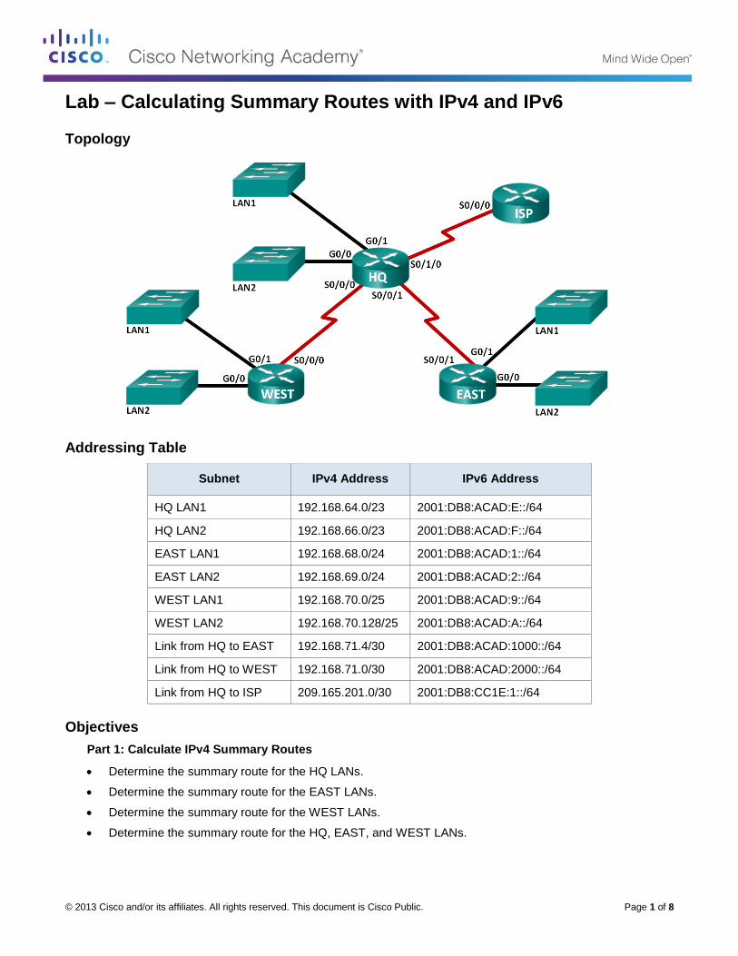
© 2013 Cisco and/or its affiliates. All rights reserved. This document is Cisco Public. Page 1 of 8
Lab – Calculating Summary Routes with IPv4 and IPv6
Topology
Addressing Table
Subnet IPv4 Address IPv6 Address
HQ LAN1 192.168.64.0/23 2001:DB8:ACAD:E::/64
HQ LAN2 192.168.66.0/23 2001:DB8:ACAD:F::/64
EAST LAN1 192.168.68.0/24 2001:DB8:ACAD:1::/64
EAST LAN2 192.168.69.0/24 2001:DB8:ACAD:2::/64
WEST LAN1 192.168.70.0/25 2001:DB8:ACAD:9::/64
WEST LAN2 192.168.70.128/25 2001:DB8:ACAD:A::/64
Link from HQ to EAST 192.168.71.4/30 2001:DB8:ACAD:1000::/64
Link from HQ to WEST 192.168.71.0/30 2001:DB8:ACAD:2000::/64
Link from HQ to ISP 209.165.201.0/30 2001:DB8:CC1E:1::/64
Objectives
Part 1: Calculate IPv4 Summary Routes
Determine the summary route for the HQ LANs.
Determine the summary route for the EAST LANs.
Determine the summary route for the WEST LANs.
Determine the summary route for the HQ, EAST, and WEST LANs.
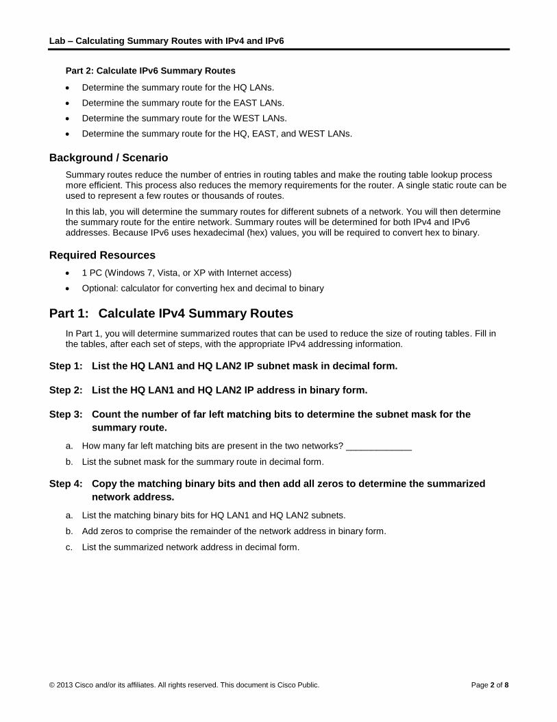
Lab – Calculating Summary Routes with IPv4 and IPv6
© 2013 Cisco and/or its affiliates. All rights reserved. This document is Cisco Public. Page 2 of 8
Part 2: Calculate IPv6 Summary Routes
Determine the summary route for the HQ LANs.
Determine the summary route for the EAST LANs.
Determine the summary route for the WEST LANs.
Determine the summary route for the HQ, EAST, and WEST LANs.
Background / Scenario
Summary routes reduce the number of entries in routing tables and make the routing table lookup process more efficient. This process also reduces the memory requirements for the router. A single static route can be used to represent a few routes or thousands of routes.
In this lab, you will determine the summary routes for different subnets of a network. You will then determine the summary route for the entire network. Summary routes will be determined for both IPv4 and IPv6 addresses. Because IPv6 uses hexadecimal (hex) values, you will be required to convert hex to binary.
Required Resources
1 PC (Windows 7, Vista, or XP with Internet access)
Optional: calculator for converting hex and decimal to binary
Part 1: Calculate IPv4 Summary Routes
In Part 1, you will determine summarized routes that can be used to reduce the size of routing tables. Fill in the tables, after each set of steps, with the appropriate IPv4 addressing information.
Step 1: List the HQ LAN1 and HQ LAN2 IP subnet mask in decimal form.
Step 2: List the HQ LAN1 and HQ LAN2 IP address in binary form.
Step 3: Count the number of far left matching bits to determine the subnet mask for the
summary route.
a. How many far left matching bits are present in the two networks? _____________
b. List the subnet mask for the summary route in decimal form.
Step 4: Copy the matching binary bits and then add all zeros to determine the summarized
network address.
a. List the matching binary bits for HQ LAN1 and HQ LAN2 subnets.
b. Add zeros to comprise the remainder of the network address in binary form.
c. List the summarized network address in decimal form.
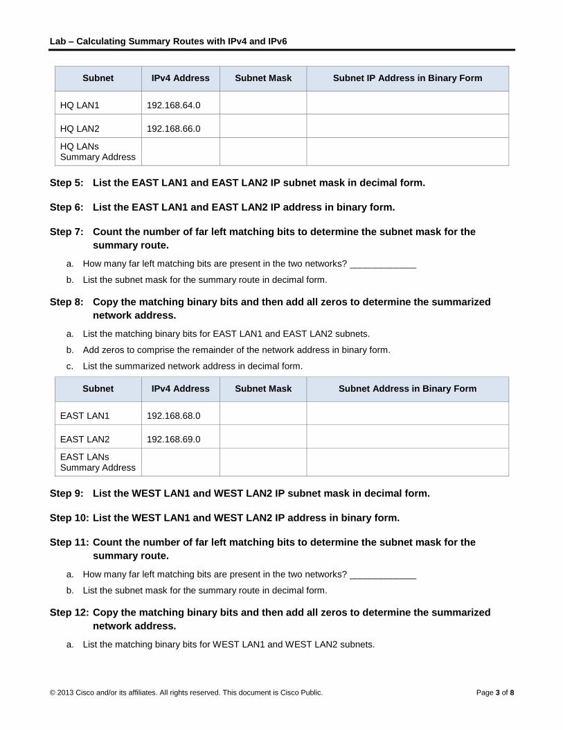
Lab – Calculating Summary Routes with IPv4 and IPv6
© 2013 Cisco and/or its affiliates. All rights reserved. This document is Cisco Public. Page 3 of 8
Subnet IPv4 Address Subnet Mask Subnet IP Address in Binary Form
HQ LAN1 192.168.64.0
HQ LAN2 192.168.66.0
HQ LANs Summary Address
Step 5: List the EAST LAN1 and EAST LAN2 IP subnet mask in decimal form.
Step 6: List the EAST LAN1 and EAST LAN2 IP address in binary form.
Step 7: Count the number of far left matching bits to determine the subnet mask for the
summary route.
a. How many far left matching bits are present in the two networks? _____________
b. List the subnet mask for the summary route in decimal form.
Step 8: Copy the matching binary bits and then add all zeros to determine the summarized
network address.
a. List the matching binary bits for EAST LAN1 and EAST LAN2 subnets.
b. Add zeros to comprise the remainder of the network address in binary form.
c. List the summarized network address in decimal form.
Subnet IPv4 Address Subnet Mask Subnet Address in Binary Form
EAST LAN1 192.168.68.0
EAST LAN2 192.168.69.0
EAST LANs Summary Address
Step 9: List the WEST LAN1 and WEST LAN2 IP subnet mask in decimal form.
Step 10: List the WEST LAN1 and WEST LAN2 IP address in binary form.
Step 11: Count the number of far left matching bits to determine the subnet mask for the
summary route.
a. How many far left matching bits are present in the two networks? _____________
b. List the subnet mask for the summary route in decimal form.
Step 12: Copy the matching binary bits and then add all zeros to determine the summarized
network address.
a. List the matching binary bits for WEST LAN1 and WEST LAN2 subnets.
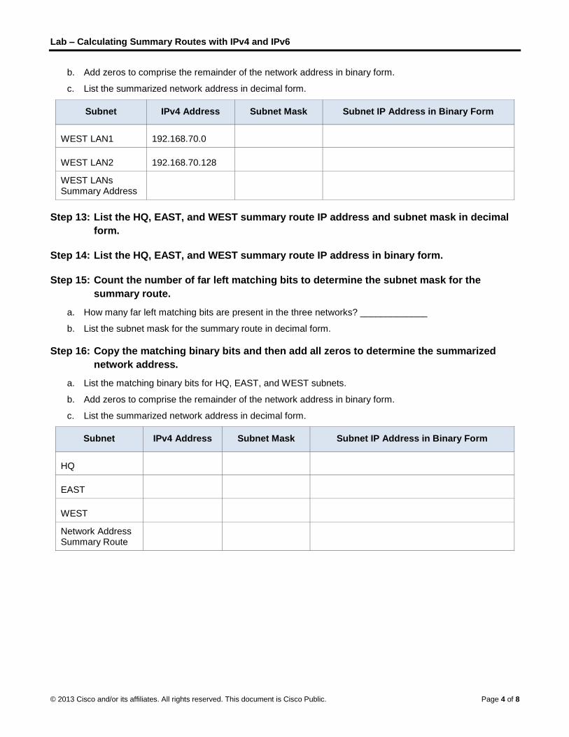
Lab – Calculating Summary Routes with IPv4 and IPv6
© 2013 Cisco and/or its affiliates. All rights reserved. This document is Cisco Public. Page 4 of 8
b. Add zeros to comprise the remainder of the network address in binary form.
c. List the summarized network address in decimal form.
Subnet IPv4 Address Subnet Mask Subnet IP Address in Binary Form
WEST LAN1 192.168.70.0
WEST LAN2 192.168.70.128
WEST LANs Summary Address
Step 13: List the HQ, EAST, and WEST summary route IP address and subnet mask in decimal
form.
Step 14: List the HQ, EAST, and WEST summary route IP address in binary form.
Step 15: Count the number of far left matching bits to determine the subnet mask for the
summary route.
a. How many far left matching bits are present in the three networks? _____________
b. List the subnet mask for the summary route in decimal form.
Step 16: Copy the matching binary bits and then add all zeros to determine the summarized
network address.
a. List the matching binary bits for HQ, EAST, and WEST subnets.
b. Add zeros to comprise the remainder of the network address in binary form.
c. List the summarized network address in decimal form.
Subnet IPv4 Address Subnet Mask Subnet IP Address in Binary Form
HQ
EAST
WEST
Network Address Summary Route
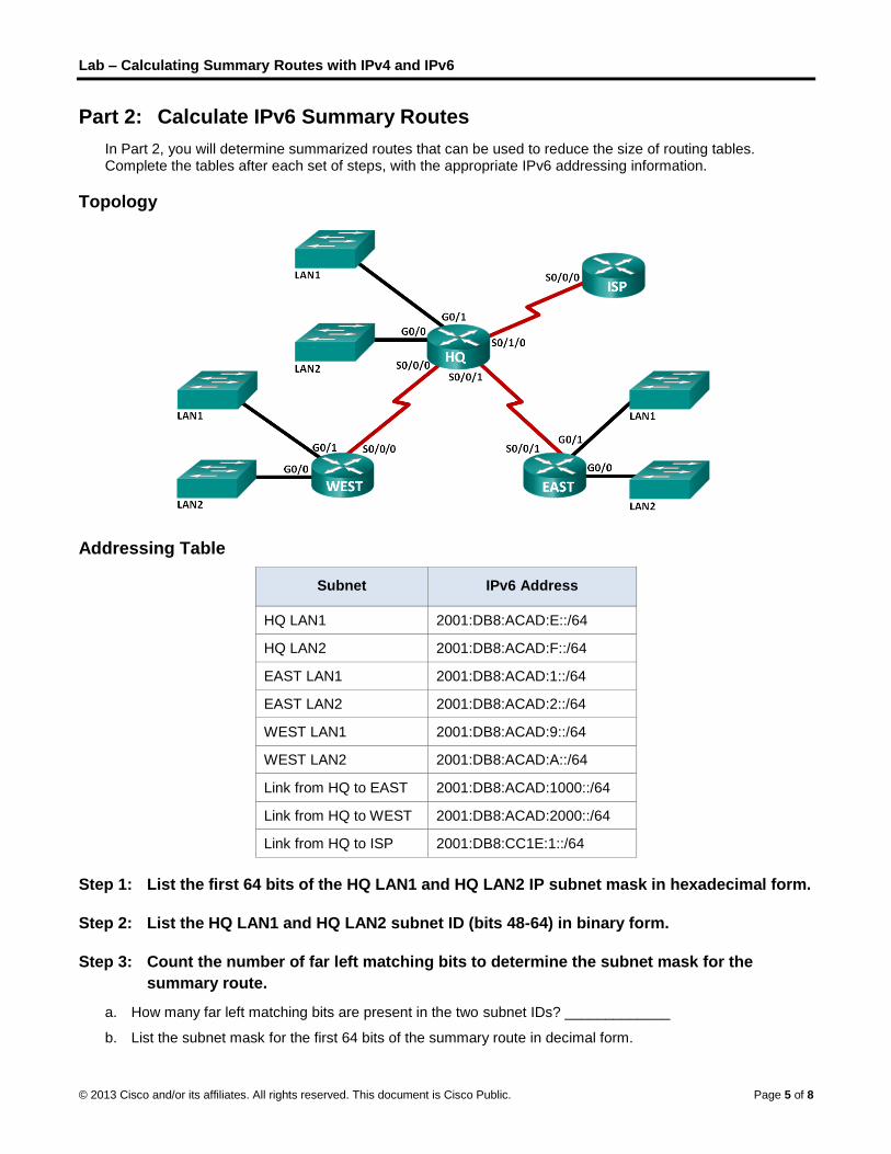
Lab – Calculating Summary Routes with IPv4 and IPv6
© 2013 Cisco and/or its affiliates. All rights reserved. This document is Cisco Public. Page 5 of 8
Part 2: Calculate IPv6 Summary Routes
In Part 2, you will determine summarized routes that can be used to reduce the size of routing tables. Complete the tables after each set of steps, with the appropriate IPv6 addressing information.
Topology
Addressing Table
Subnet IPv6 Address
HQ LAN1 2001:DB8:ACAD:E::/64
HQ LAN2 2001:DB8:ACAD:F::/64
EAST LAN1 2001:DB8:ACAD:1::/64
EAST LAN2 2001:DB8:ACAD:2::/64
WEST LAN1 2001:DB8:ACAD:9::/64
WEST LAN2 2001:DB8:ACAD:A::/64
Link from HQ to EAST 2001:DB8:ACAD:1000::/64
Link from HQ to WEST 2001:DB8:ACAD:2000::/64
Link from HQ to ISP 2001:DB8:CC1E:1::/64
Step 1: List the first 64 bits of the HQ LAN1 and HQ LAN2 IP subnet mask in hexadecimal form.
Step 2: List the HQ LAN1 and HQ LAN2 subnet ID (bits 48-64) in binary form.
Step 3: Count the number of far left matching bits to determine the subnet mask for the
summary route.
a. How many far left matching bits are present in the two subnet IDs? _____________
b. List the subnet mask for the first 64 bits of the summary route in decimal form.
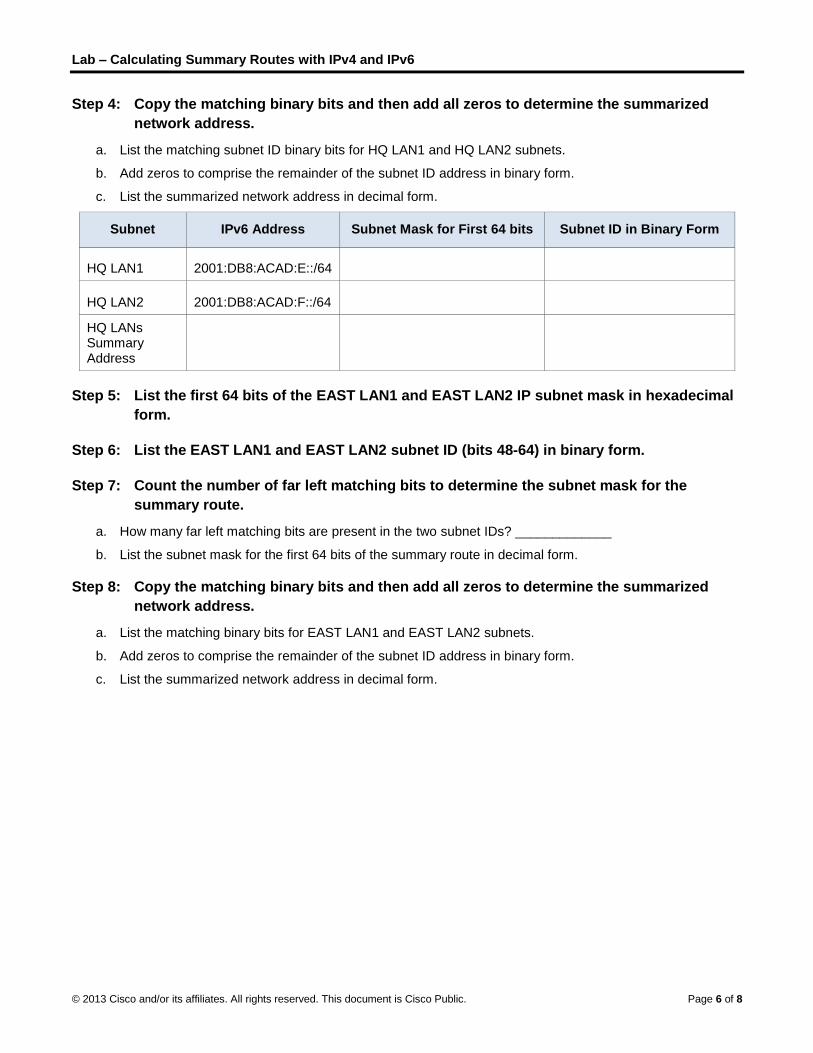
Lab – Calculating Summary Routes with IPv4 and IPv6
© 2013 Cisco and/or its affiliates. All rights reserved. This document is Cisco Public. Page 6 of 8
Step 4: Copy the matching binary bits and then add all zeros to determine the summarized
network address.
a. List the matching subnet ID binary bits for HQ LAN1 and HQ LAN2 subnets.
b. Add zeros to comprise the remainder of the subnet ID address in binary form.
c. List the summarized network address in decimal form.
Subnet IPv6 Address Subnet Mask for First 64 bits Subnet ID in Binary Form
HQ LAN1 2001:DB8:ACAD:E::/64
HQ LAN2 2001:DB8:ACAD:F::/64
HQ LANs Summary Address
Step 5: List the first 64 bits of the EAST LAN1 and EAST LAN2 IP subnet mask in hexadecimal
form.
Step 6: List the EAST LAN1 and EAST LAN2 subnet ID (bits 48-64) in binary form.
Step 7: Count the number of far left matching bits to determine the subnet mask for the
summary route.
a. How many far left matching bits are present in the two subnet IDs? _____________
b. List the subnet mask for the first 64 bits of the summary route in decimal form.
Step 8: Copy the matching binary bits and then add all zeros to determine the summarized
network address.
a. List the matching binary bits for EAST LAN1 and EAST LAN2 subnets.
b. Add zeros to comprise the remainder of the subnet ID address in binary form.
c. List the summarized network address in decimal form.
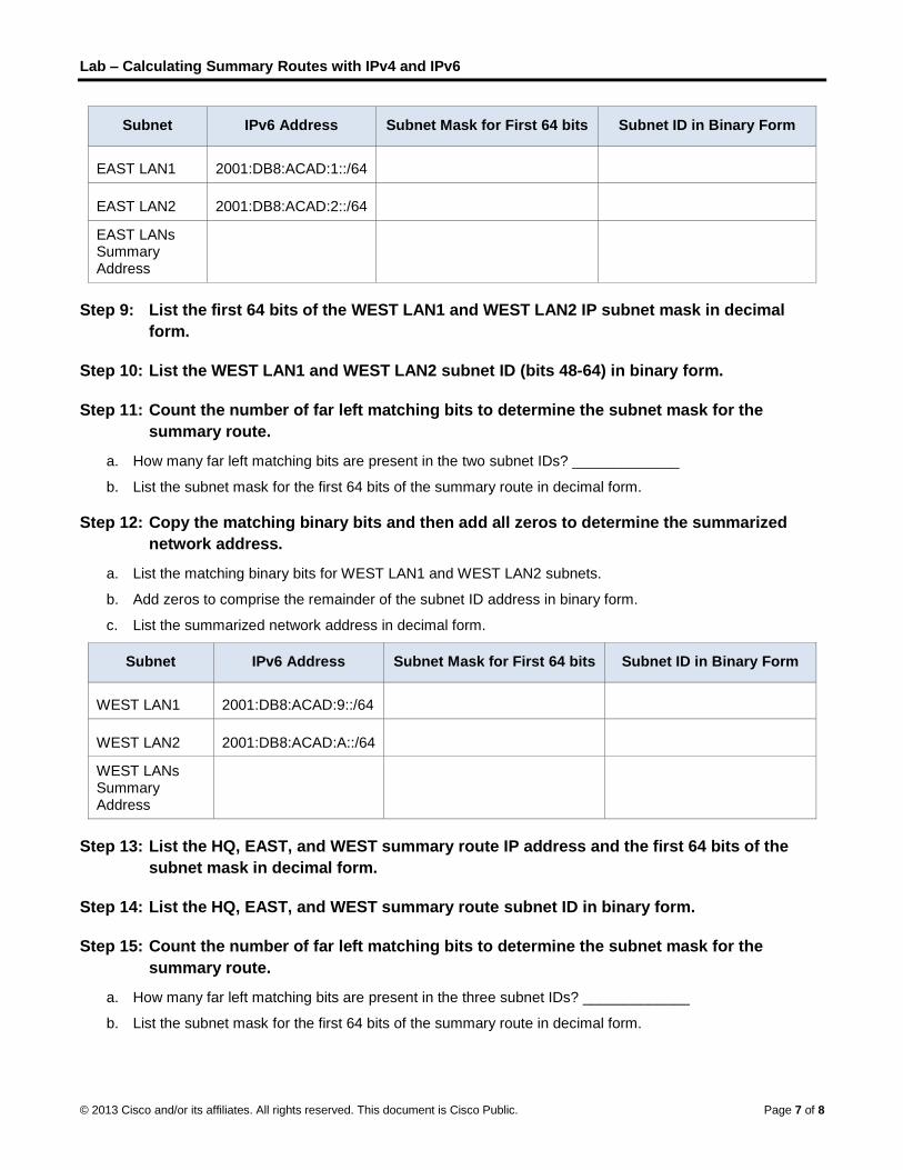
Lab – Calculating Summary Routes with IPv4 and IPv6
© 2013 Cisco and/or its affiliates. All rights reserved. This document is Cisco Public. Page 7 of 8
Subnet IPv6 Address Subnet Mask for First 64 bits Subnet ID in Binary Form
EAST LAN1 2001:DB8:ACAD:1::/64
EAST LAN2 2001:DB8:ACAD:2::/64
EAST LANs Summary Address
Step 9: List the first 64 bits of the WEST LAN1 and WEST LAN2 IP subnet mask in decimal
form.
Step 10: List the WEST LAN1 and WEST LAN2 subnet ID (bits 48-64) in binary form.
Step 11: Count the number of far left matching bits to determine the subnet mask for the
summary route.
a. How many far left matching bits are present in the two subnet IDs? _____________
b. List the subnet mask for the first 64 bits of the summary route in decimal form.
Step 12: Copy the matching binary bits and then add all zeros to determine the summarized
network address.
a. List the matching binary bits for WEST LAN1 and WEST LAN2 subnets.
b. Add zeros to comprise the remainder of the subnet ID address in binary form.
c. List the summarized network address in decimal form.
Subnet IPv6 Address Subnet Mask for First 64 bits Subnet ID in Binary Form
WEST LAN1 2001:DB8:ACAD:9::/64
WEST LAN2 2001:DB8:ACAD:A::/64
WEST LANs Summary Address
Step 13: List the HQ, EAST, and WEST summary route IP address and the first 64 bits of the
subnet mask in decimal form.
Step 14: List the HQ, EAST, and WEST summary route subnet ID in binary form.
Step 15: Count the number of far left matching bits to determine the subnet mask for the
summary route.
a. How many far left matching bits are present in the three subnet IDs? _____________
b. List the subnet mask for the first 64 bits of the summary route in decimal form.

Lab – Calculating Summary Routes with IPv4 and IPv6
© 2013 Cisco and/or its affiliates. All rights reserved. This document is Cisco Public. Page 8 of 8
Step 16: Copy the matching binary bits and then add all zeros to determine the summarized
network address.
a. List the matching binary bits for HQ, EAST, and WEST subnets.
b. Add zeros to comprise the remainder of the subnet ID address in binary form.
c. List the summarized network address in decimal form.
Subnet IPv6 Address Subnet Mask for first 64 bits Subnet ID in Binary Form
HQ
EAST
WEST
Network Address Summary Route
Reflection
1. How is determining the summary route for IPv4 different from IPv6?
_______________________________________________________________________________________
_______________________________________________________________________________________
_______________________________________________________________________________________
2. Why are summary routes beneficial to a network?
_______________________________________________________________________________________
_______________________________________________________________________________________
_______________________________________________________________________________________

© 2013 Cisco and/or its affiliates. All rights reserved. This document is Cisco Public. Page 1 of 1
Lab – Troubleshooting IPv4 and IPv6 Static Routes
Topology

Lab – Troubleshooting IPv4 and IPv6 Static Routes
© 2013 Cisco and/or its affiliates. All rights reserved. This document is Cisco Public. Page 2 of 2
Addressing Table
Device Interface IP Address Default Gateway
HQ G0/1
192.168.0.1/25
2001:DB8:ACAD::1/64
FE80::1 link-local N/A
S0/0/0 (DCE)
10.1.1.2/30
2001:DB8:ACAD::20:2/64 N/A
S0/0/1
192.168.0.253/30
2001:DB8:ACAD:2::1/30 N/A
ISP G0/0
172.16.3.1/24
2001:DB8:ACAD:30::1/64
FE80::1 link-local N/A
S0/0/0
10.1.1.1/30
2001:DB8:ACAD:20::/64 N/A
BRANCH G0/1
192.168.1.1/24
2001:DB8:ACAD:1::1/64
FE80::1 link-local N/A
S0/0/0 (DCE)
192.168.0.254/30
2001:DB8:ACAD:2::2/64 N/A
S1 VLAN 1 N/A N/A
S3 VLAN 1 N/A N/A
PC-A NIC
192.168.0.3/25
2001:DB8:ACAD::3/64
192.168.0.1
FE80::1
Web Server NIC
172.16.3.3/24
2001:DB8:ACAD:30::3/64
172.16.3.1
FE80::1
PC-C NIC
192.168.1.3/24
2001:DB8:ACAD:1::3/64
192.168.1.1
FE80::1
Objectives
Part 1: Build the Network and Configure Basic Device Settings
Part 2: Troubleshoot Static Routes in an IPv4 Network
Part 3: Troubleshoot Static Routes in an IPv6 Network
Required Resources
3 Routers (Cisco 1941 with Cisco IOS Release 15.2(4)M3 universal image or comparable)
2 Switches (Cisco 2960 with Cisco IOS Release 15.0(2) lanbasek9 image or comparable)
3 PCs (Windows 7, Vista, or XP with terminal emulation program, such as Tera Term)
Console cables to configure the Cisco IOS devices via the console ports

Lab – Troubleshooting IPv4 and IPv6 Static Routes
© 2013 Cisco and/or its affiliates. All rights reserved. This document is Cisco Public. Page 3 of 3
Ethernet and serial cables as shown in the topology
Part 1: Build the Network and Configure Basic Device Settings
In Part 1, you will set up the network topology and configure the routers and switches with some basic settings, such as passwords and IP addresses. Preset configurations are also provided for you for the initial router configurations. You will also configure the IP settings for the PCs in the topology.
Step 1: Cable the network as shown in the topology.
Attach the devices as shown in the topology diagram and cable, as necessary.
Step 2: Initialize and reload the routers and switches.
Step 3: Configure basic settings for each router.
a. Disable DNS lookup.
b. Configure device name as shown in the topology.
c. Assign class as the privileged EXEC mode password.
d. Assign cisco as the console and vty passwords.
e. Configure logging synchronous to prevent console messages from interrupting command entry.
Step 4: Configure hosts and Web Server.
a. Configure IP addresses for IPv4 and IPv6.
b. Configure IPv4 default gateway.
Step 5: Load router configurations.
Router HQ
hostname HQ
ipv6 unicast-routing
interface GigabitEthernet0/1
ipv6 address 2001:DB8:ACAD::1/64
ip address 192.168.0.1 255.255.255.128
ipv6 address FE80::1 link-local
interface Serial0/0/0
ipv6 address 2001:DB8:ACAD:20::2/64
ip address 10.1.1.2 255.255.255.252
clock rate 800000
no shutdown
interface Serial0/0/1
ipv6 address 2001:DB8:ACAD:2::3/64
ip address 192.168.0.253 255.255.255.252
no shutdown
ip route 172.16.3.0 255.255.255.0 10.1.1.1
ip route 192.168.1.0 255.255.255.0 192.16.0.254
ipv6 route 2001:DB8:ACAD:1::/64 2001:DB8:ACAD:2::2
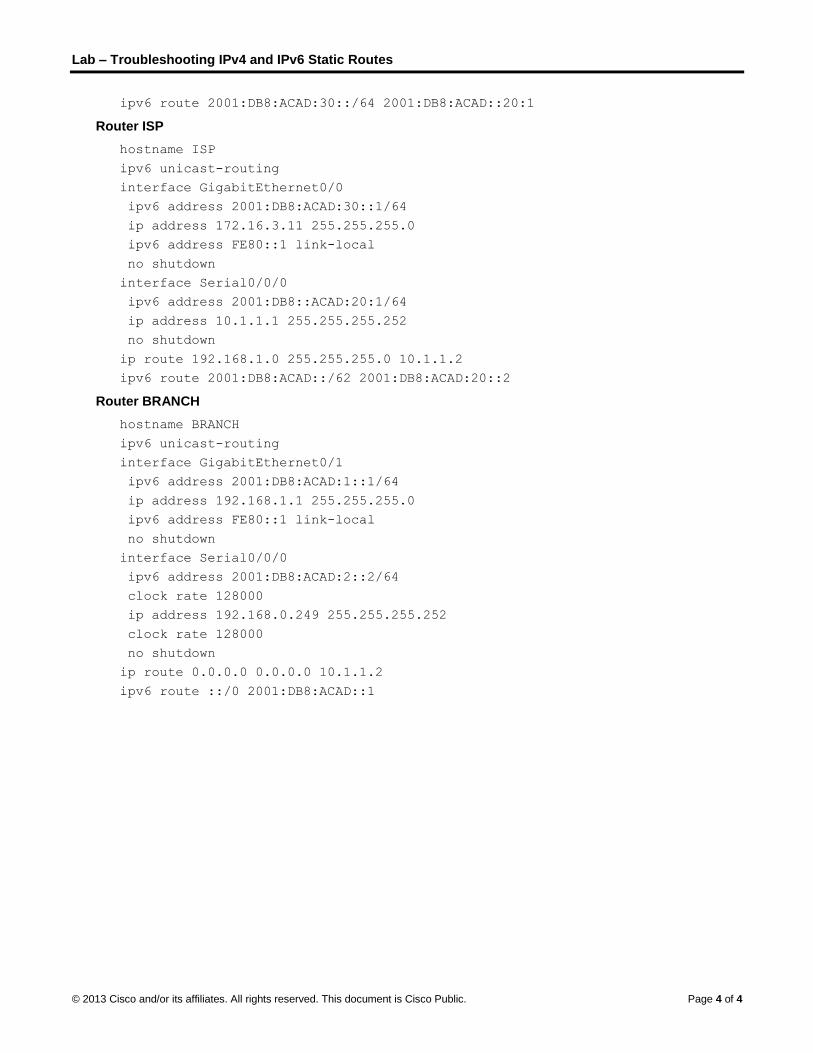
Lab – Troubleshooting IPv4 and IPv6 Static Routes
© 2013 Cisco and/or its affiliates. All rights reserved. This document is Cisco Public. Page 4 of 4
ipv6 route 2001:DB8:ACAD:30::/64 2001:DB8:ACAD::20:1
Router ISP
hostname ISP
ipv6 unicast-routing
interface GigabitEthernet0/0
ipv6 address 2001:DB8:ACAD:30::1/64
ip address 172.16.3.11 255.255.255.0
ipv6 address FE80::1 link-local
no shutdown
interface Serial0/0/0
ipv6 address 2001:DB8::ACAD:20:1/64
ip address 10.1.1.1 255.255.255.252
no shutdown
ip route 192.168.1.0 255.255.255.0 10.1.1.2
ipv6 route 2001:DB8:ACAD::/62 2001:DB8:ACAD:20::2
Router BRANCH
hostname BRANCH
ipv6 unicast-routing
interface GigabitEthernet0/1
ipv6 address 2001:DB8:ACAD:1::1/64
ip address 192.168.1.1 255.255.255.0
ipv6 address FE80::1 link-local
no shutdown
interface Serial0/0/0
ipv6 address 2001:DB8:ACAD:2::2/64
clock rate 128000
ip address 192.168.0.249 255.255.255.252
clock rate 128000
no shutdown
ip route 0.0.0.0 0.0.0.0 10.1.1.2
ipv6 route ::/0 2001:DB8:ACAD::1

Lab – Troubleshooting IPv4 and IPv6 Static Routes
© 2013 Cisco and/or its affiliates. All rights reserved. This document is Cisco Public. Page 5 of 5
Part 2: Troubleshoot Static Routes in an IPv4 Network
IPv4 Addressing Table
Device Interface IP Address Subnet Mask Default Gateway
HQ G0/1 192.168.0.1 255.255.255.0 N/A
S0/0/0 (DCE) 10.1.1.2 255.255.255.252 N/A
S0/0/1 192.168.0.253 255.255.255.252 N/A
ISP G0/0 172.16.3.1 255.255.255.0 N/A
S0/0/0 10.1.1.1 255.255.255.252 N/A
BRANCH G0/1 192.168.1.1 255.255.255.0 N/A
S0/0/0 (DCE) 192.168.0.254 255.255.255.252 N/A
S1 VLAN 1 192.168.0.11 255.255.255.128 192.168.0.1
S3 VLAN 1 192.168.1.11 255.255.255.0 192.168.1.1
PC-A NIC 192.168.0.3 255.255.255.128 192.168.0.1
Web Server NIC 172.16.3.3 255.255.255.0 172.16.3.1
PC-C NIC 192.168.1.3 255.255.255.0 192.168.1.1
Step 1: Troubleshoot the HQ router.
The HQ router is the link between the ISP router and the BRANCH router. The ISP router represents the outside network while the BRANCH router represents the corporate network. The HQ router is configured with static routes to ISP and BRANCH networks.
a. Display the status of the interfaces on HQ. Enter show ip interface brief. Record and resolve any issues as necessary.
____________________________________________________________________________________
b. Ping from HQ router to BRANCH router (192.168.0.254). Were the pings successful? ________
c. Ping from HQ router to ISP router (10.1.1.1). Were the pings successful? ________
d. Ping from PC-A to the default gateway. Were the pings successful? ________
e. Ping from PC-A to PC-C. Were the pings successful? ________
f. Ping from PC-A to Web Server. Were the pings successful? ________
g. Display the routing table on HQ. What non-directly connected routes are shown in the routing table?
____________________________________________________________________________________
____________________________________________________________________________________
h. Based on the results of the pings, routing table output, and static routes in the running configuration, what can you conclude about network connectivity?
____________________________________________________________________________________
____________________________________________________________________________________
____________________________________________________________________________________
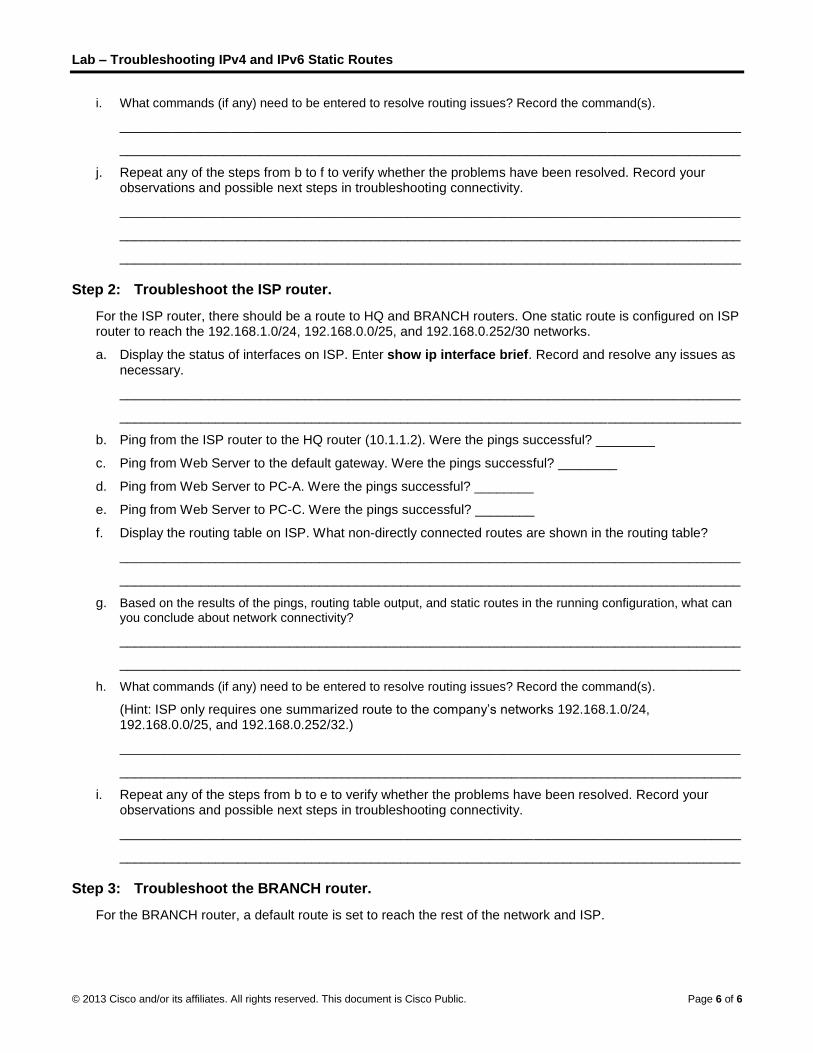
Lab – Troubleshooting IPv4 and IPv6 Static Routes
© 2013 Cisco and/or its affiliates. All rights reserved. This document is Cisco Public. Page 6 of 6
i. What commands (if any) need to be entered to resolve routing issues? Record the command(s).
____________________________________________________________________________________
____________________________________________________________________________________
j. Repeat any of the steps from b to f to verify whether the problems have been resolved. Record your observations and possible next steps in troubleshooting connectivity.
____________________________________________________________________________________
____________________________________________________________________________________
____________________________________________________________________________________
Step 2: Troubleshoot the ISP router.
For the ISP router, there should be a route to HQ and BRANCH routers. One static route is configured on ISP router to reach the 192.168.1.0/24, 192.168.0.0/25, and 192.168.0.252/30 networks.
a. Display the status of interfaces on ISP. Enter show ip interface brief. Record and resolve any issues as necessary.
____________________________________________________________________________________
____________________________________________________________________________________
b. Ping from the ISP router to the HQ router (10.1.1.2). Were the pings successful? ________
c. Ping from Web Server to the default gateway. Were the pings successful? ________
d. Ping from Web Server to PC-A. Were the pings successful? ________
e. Ping from Web Server to PC-C. Were the pings successful? ________
f. Display the routing table on ISP. What non-directly connected routes are shown in the routing table?
____________________________________________________________________________________
____________________________________________________________________________________
g. Based on the results of the pings, routing table output, and static routes in the running configuration, what can you conclude about network connectivity?
____________________________________________________________________________________
____________________________________________________________________________________
h. What commands (if any) need to be entered to resolve routing issues? Record the command(s).
(Hint: ISP only requires one summarized route to the company’s networks 192.168.1.0/24, 192.168.0.0/25, and 192.168.0.252/32.)
____________________________________________________________________________________
____________________________________________________________________________________
i. Repeat any of the steps from b to e to verify whether the problems have been resolved. Record your observations and possible next steps in troubleshooting connectivity.
____________________________________________________________________________________
____________________________________________________________________________________
Step 3: Troubleshoot the BRANCH router.
For the BRANCH router, a default route is set to reach the rest of the network and ISP.

Lab – Troubleshooting IPv4 and IPv6 Static Routes
© 2013 Cisco and/or its affiliates. All rights reserved. This document is Cisco Public. Page 7 of 7
a. Display the status of the interfaces on BRANCH. Enter show ip interface brief. Record and resolve any issues, as necessary.
____________________________________________________________________________________
____________________________________________________________________________________
b. Ping from the BRANCH router to the HQ router (192.168.0.253). Were the pings successful? ________
c. Ping from PC-C to the default gateway. Were the pings successful? ________
d. Ping from PC-C to PC-A. Were the pings successful? ________
e. Ping from PC-C to Web Server. Were the pings successful? ________
f. Display the routing table on BRANCH. What non-directly connected routes are shown in the routing table?
____________________________________________________________________________________
g. Based on the results of the pings, routing table output, and static routes in the running configuration, what can you conclude about network connectivity?
____________________________________________________________________________________
____________________________________________________________________________________
h. What commands (if any) need to be entered to resolve routing issues? Record the command(s).
____________________________________________________________________________________
____________________________________________________________________________________
i. Repeat any of the steps from b to e to verify whether the problems have been resolved. Record your observations and possible next steps in troubleshooting connectivity.
____________________________________________________________________________________
____________________________________________________________________________________

Lab – Troubleshooting IPv4 and IPv6 Static Routes
© 2013 Cisco and/or its affiliates. All rights reserved. This document is Cisco Public. Page 8 of 8
Part 3: Troubleshoot Static Routes in an IPv6 Network
Device Interface IPv6 Address Prefix Length Default Gateway
HQ G0/1 2001:DB8:ACAD::1 64 N/A
S0/0/0 (DCE) 2001:DB8:ACAD::20:2 64 N/A
S0/0/1 2001:DB8:ACAD:2::1 64 N/A
ISP G0/0 2001:DB8:ACAD:30::1 64 N/A
S0/0/0 2001:DB8:ACAD:20::1 64 N/A
BRANCH G0/1 2001:DB8:ACAD:1::1 64 N/A
S0/0/0 (DCE) 2001:DB8:ACAD:2::2 64 N/A
PC-A NIC 2001:DB8:ACAD::3 64 FE80::1
Web Server NIC 2001:DB8:ACAD:30::3 64 FE80::1
PC-C NIC 2001:DB8:ACAD:1::3 64 FE80::1
Step 1: Troubleshoot the HQ router.
The HQ router is the link between the ISP router and the BRANCH router. The ISP router represents the outside network while the BRANCH router represents the corporate network. The HQ router is configured with static routes to both the ISP and the BRANCH networks.
a. Display the status of the interfaces on HQ. Enter show ipv6 interface brief. Record and resolve any issues, as necessary.
____________________________________________________________________________________
____________________________________________________________________________________
b. Ping from the HQ router to the BRANCH router (2001:DB8:ACAD:2::2). Were the pings successful? ____
c. Ping from the HQ router to the ISP router (2001:DB8:ACAD:20::1). Were the pings successful? ________
d. Ping from PC-A to the default gateway. Were the pings successful? ________
e. Ping from PC-A to Web Server. Were the pings successful? ________
f. Ping from PC-A to PC-C. Were the pings successful? ________
g. Display the routing table by issuing a show ipv6 route command. What non-directly connected routes are shown in the routing table?
____________________________________________________________________________________
____________________________________________________________________________________
h. Based on the results of the pings, routing table output, and static routes in the running configuration, what can you conclude about network connectivity?
____________________________________________________________________________________
____________________________________________________________________________________
i. What commands (if any) need to be entered to resolve routing issues? Record the command(s).
____________________________________________________________________________________
____________________________________________________________________________________

Lab – Troubleshooting IPv4 and IPv6 Static Routes
© 2013 Cisco and/or its affiliates. All rights reserved. This document is Cisco Public. Page 9 of 9
j. Repeat any of the steps from b to f to verify whether the problems have been resolved. Record your observations and possible next steps in troubleshooting connectivity.
____________________________________________________________________________________
____________________________________________________________________________________
Step 2: Troubleshoot the ISP router.
On the ISP router, one static route is configured to reach all the networks on HQ and BRANCH routers.
a. Display the status of the interfaces on ISP. Enter show ipv6 interface brief. Record and resolve any issues, as necessary.
____________________________________________________________________________________
____________________________________________________________________________________
b. Ping from the ISP router to the HQ router (2001:DB8:ACAD:20::2). Were the pings successful? ________
c. Ping from Web Server to the default gateway. Were the pings successful? ________
d. Ping from Web Server to PC-A. Were the pings successful? ________
e. Ping from Web Server to PC-C. Were the pings successful? ________
f. Display the routing table. What non-directly connected routes are shown in the routing table?
____________________________________________________________________________________
____________________________________________________________________________________
g. Based on the results of the pings, routing table output, and static routes in the running configuration, what can you conclude about network connectivity?
____________________________________________________________________________________
____________________________________________________________________________________
h. What commands (if any) need to be entered to resolve routing issues? Record the command(s).
____________________________________________________________________________________
____________________________________________________________________________________
i. Repeat any of the steps from b to e to verify whether the problems have been resolved. Record your observations and possible next steps in troubleshooting connectivity.
____________________________________________________________________________________
____________________________________________________________________________________
Step 3: Troubleshoot the BRANCH router.
For the BRANCH routers, there is a default route to the HQ router. This default route allows the BRANCH network to the ISP router and Web Server.
a. Display the status of the interfaces on BRANCH. Enter show ipv6 interface brief. Record and resolve any issues, as necessary.
____________________________________________________________________________________
____________________________________________________________________________________
b. Ping from the BRANCH router to the HQ router (2001:DB8:ACAD:2::1). Were the pings successful? ________
c. Ping from the BRANCH router to the ISP router (2001:DB8:ACAD:20::1). Were the pings successful? ________

Lab – Troubleshooting IPv4 and IPv6 Static Routes
© 2013 Cisco and/or its affiliates. All rights reserved. This document is Cisco Public. Page 10 of 10
d. Ping from PC-C to the default gateway. Were the pings successful? ________
e. Ping from PC-C to PC-A. Were the pings successful? ________
f. Ping from PC-C to Web Server. Were the pings successful? ________
g. Display the routing table. What non-directly connected routes are shown in the routing table?
____________________________________________________________________________________
____________________________________________________________________________________
h. Based on the results of the pings, routing table output, and static routes in the running configuration, what can you conclude about network connectivity?
____________________________________________________________________________________
____________________________________________________________________________________
i. What commands (if any) need to be entered to resolve routing issues? Record the command(s).
____________________________________________________________________________________
____________________________________________________________________________________
j. Repeat any of the steps from b to f to verify whether the problems have been resolved. Record your observations and possible next steps in troubleshooting connectivity.
____________________________________________________________________________________
____________________________________________________________________________________

© 2013 Cisco and/or its affiliates. All rights reserved. This document is Cisco Public. Page 1 of 12
Lab – Configuring Basic RIPv2 and RIPng
Topology
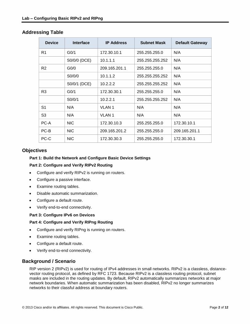
Lab – Configuring Basic RIPv2 and RIPng
© 2013 Cisco and/or its affiliates. All rights reserved. This document is Cisco Public. Page 2 of 12
Addressing Table
Device Interface IP Address Subnet Mask Default Gateway
R1 G0/1 172.30.10.1 255.255.255.0 N/A
S0/0/0 (DCE) 10.1.1.1 255.255.255.252 N/A
R2 G0/0 209.165.201.1 255.255.255.0 N/A
S0/0/0 10.1.1.2 255.255.255.252 N/A
S0/0/1 (DCE) 10.2.2.2 255.255.255.252 N/A
R3 G0/1 172.30.30.1 255.255.255.0 N/A
S0/0/1 10.2.2.1 255.255.255.252 N/A
S1 N/A VLAN 1 N/A N/A
S3 N/A VLAN 1 N/A N/A
PC-A NIC 172.30.10.3 255.255.255.0 172.30.10.1
PC-B NIC 209.165.201.2 255.255.255.0 209.165.201.1
PC-C NIC 172.30.30.3 255.255.255.0 172.30.30.1
Objectives
Part 1: Build the Network and Configure Basic Device Settings
Part 2: Configure and Verify RIPv2 Routing
Configure and verify RIPv2 is running on routers.
Configure a passive interface.
Examine routing tables.
Disable automatic summarization.
Configure a default route.
Verify end-to-end connectivity.
Part 3: Configure IPv6 on Devices
Part 4: Configure and Verify RIPng Routing
Configure and verify RIPng is running on routers.
Examine routing tables.
Configure a default route.
Verify end-to-end connectivity.
Background / Scenario
RIP version 2 (RIPv2) is used for routing of IPv4 addresses in small networks. RIPv2 is a classless, distance-vector routing protocol, as defined by RFC 1723. Because RIPv2 is a classless routing protocol, subnet masks are included in the routing updates. By default, RIPv2 automatically summarizes networks at major network boundaries. When automatic summarization has been disabled, RIPv2 no longer summarizes networks to their classful address at boundary routers.

Lab – Configuring Basic RIPv2 and RIPng
© 2013 Cisco and/or its affiliates. All rights reserved. This document is Cisco Public. Page 3 of 12
RIPng (RIP Next Generation) is a distance-vector routing protocol for routing IPv6 addresses, as defined by RFC 2080. RIPng is based on RIPv2 and has the same administrative distance and 15-hop limitation.
In this lab, you will configure the network topology with RIPv2 routing, disable automatic summarization, propagate a default route, and use CLI commands to display and verify RIP routing information. You will then configure the network topology with IPv6 addresses, configure RIPng, propagate a default route, and use CLI commands to display and verify RIPng routing information.
Note: The routers used with CCNA hands-on labs are Cisco 1941 Integrated Services Routers (ISRs) with Cisco IOS Release 15.2(4)M3 (universalk9 image). The switches used are Cisco Catalyst 2960s with Cisco IOS Release 15.0(2) (lanbasek9 image). Other routers, switches, and Cisco IOS versions can be used. Depending on the model and Cisco IOS version, the commands available and output produced might vary from what is shown in the labs. Refer to the Router Interface Summary Table at the end of the lab for the correct interface identifiers.
Note: Make sure that the routers and switches have been erased and have no startup configurations. If you are unsure, contact your instructor.
Required Resources
3 Routers (Cisco 1941 with Cisco IOS Release 15.2(4)M3 universal image or comparable)
2 Switches (Cisco 2960 with Cisco IOS Release 15.0(2) lanbasek9 image or comparable)
3 PCs (Windows 7, Vista, or XP with terminal emulation program, such as Tera Term)
Console cables to configure the Cisco IOS devices via the console ports
Ethernet and Serial cables as shown in the topology
Part 1: Build the Network and Configure Basic Device Settings
In Part 1, you will set up the network topology and configure basic settings.
Step 1: Cable the network as shown in the topology.
Step 2: Initialize and reload the router and switch.
Step 3: Configure basic settings for each router and switch.
a. Disable DNS lookup.
b. Configure device names as shown in the topology.
c. Configure password encryption.
d. Assign class as the privileged EXEC password.
e. Assign cisco as the console and vty passwords.
f. Configure a MOTD banner to warn users that unauthorized access is prohibited.
g. Configure logging synchronous for the console line.
h. Configure the IP address listed in the Addressing Table for all interfaces.
i. Configure a description to each interface with an IP address.
j. Configure the clock rate if applicable to the DCE serial interface.
k. Copy the running-configuration to the startup-configuration.

Lab – Configuring Basic RIPv2 and RIPng
© 2013 Cisco and/or its affiliates. All rights reserved. This document is Cisco Public. Page 4 of 12
Step 4: Configure PC hosts.
Refer to the Addressing Table for PC host address information.
Step 5: Test connectivity.
At this point, the PCs are unable to ping each other.
a. Each workstation should be able to ping the attached router. Verify and troubleshoot if necessary.
b. The routers should be able to ping one another. Verify and troubleshoot if necessary.
Part 2: Configure and Verify RIPv2 Routing
In Part 2, you will configure RIPv2 routing on all routers in the network and then verify that routing tables are updated correctly. After RIPv2 has been verified, you will disable automatic summarization, configure a default route, and verify end-to-end connectivity.
Step 1: Configure RIPv2 routing.
a. On R1, configure RIPv2 as the routing protocol and advertise the appropriate networks.
R1# config t
R1(config)# router rip
R1(config-router)# version 2
R1(config-router)# passive-interface g0/1
R1(config-router)# network 172.30.0.0
R1(config-router)# network 10.0.0.0
The passive-interface command stops routing updates out the specified interface. This process prevents unnecessary routing traffic on the LAN. However, the network that the specified interface belongs to is still advertised in routing updates that are sent out across other interfaces.
b. Configure RIPv2 on R3 and use the network statement to add appropriate networks and prevent routing updates on the LAN interface.
c. Configure RIPv2 on R2. Do not advertise the 209.165.201.0 network.
Note: It is not necessary to make the G0/0 interface passive on R2 because the network associated with this interface is not being advertised.
Step 2: Examine current state of network.
a. The status of the two serial links can quickly be verified using the show ip interface brief command on R2.
R2# show ip interface brief
Interface IP-Address OK? Method Status Protocol
Embedded-Service-Engine0/0 unassigned YES unset administratively down down
GigabitEthernet0/0 209.165.201.1 YES manual up up
GigabitEthernet0/1 unassigned YES unset administratively down down
Serial0/0/0 10.1.1.2 YES manual up up
Serial0/0/1 10.2.2.2 YES manual up up
b. Check connectivity between PCs.
From PC-A, is it possible to ping PC-B? _________ Why? _____________________________________
From PC-A, is it possible to ping PC-C? _________ Why? _____________________________________

Lab – Configuring Basic RIPv2 and RIPng
© 2013 Cisco and/or its affiliates. All rights reserved. This document is Cisco Public. Page 5 of 12
From PC-C, is it possible to ping PC-B? _________ Why? _____________________________________
From PC-C, is it possible to ping PC-A? _________ Why? _____________________________________
c. Verify that RIPv2 is running on the routers.
You can use the debug ip rip, show ip protocols, and show run commands to confirm that RIPv2 is running. The show ip protocols command output for R1 is shown below.
R1# show ip protocols
Routing Protocol is "rip"
Outgoing update filter list for all interfaces is not set
Incoming update filter list for all interfaces is not set
Sending updates every 30 seconds, next due in 7 seconds
Invalid after 180 seconds, hold down 180, flushed after 240
Redistributing: rip
Default version control: send version 2, receive 2
Interface Send Recv Triggered RIP Key-chain
Serial0/0/0 2 2
Automatic network summarization is in effect
Maximum path: 4
Routing for Networks:
10.0.0.0
172.30.0.0
Passive Interface(s):
GigabitEthernet0/1
Routing Information Sources:
Gateway Distance Last Update
10.1.1.2 120
Distance: (default is 120)
When issuing the debug ip rip command on R2, what information is provided that confirms RIPv2 is running?
____________________________________________________________________________________
When you are finished observing the debugging outputs, issue the undebug all command at the privileged EXEC prompt.
When issuing the show run command on R3, what information is provided that confirms RIPv2 is running?
____________________________________________________________________________________
____________________________________________________________________________________
d. Examine the automatic summarization of routes.
The LANs connected to R1 and R3 are composed of discontiguous networks. R2 displays two equal-cost paths to the 172.30.0.0/16 network in the routing table. R2 displays only the major classful network address of 172.30.0.0 and does not display any of the subnets for this network.
R2# show ip route
<Output omitted>
10.0.0.0/8 is variably subnetted, 4 subnets, 2 masks
C 10.1.1.0/30 is directly connected, Serial0/0/0
L 10.1.1.2/32 is directly connected, Serial0/0/0
C 10.2.2.0/30 is directly connected, Serial0/0/1

Lab – Configuring Basic RIPv2 and RIPng
© 2013 Cisco and/or its affiliates. All rights reserved. This document is Cisco Public. Page 6 of 12
L 10.2.2.2/32 is directly connected, Serial0/0/1
R 172.30.0.0/16 [120/1] via 10.2.2.1, 00:00:23, Serial0/0/1
[120/1] via 10.1.1.1, 00:00:09, Serial0/0/0
209.165.201.0/24 is variably subnetted, 2 subnets, 2 masks
C 209.165.201.0/24 is directly connected, GigabitEthernet0/0
L 209.165.201.1/32 is directly connected, GigabitEthernet0/0
R1 displays only its own subnets for the 172.30.0.0 network. R1 does not have any routes for the 172.30.0.0 subnets on R3.
R1# show ip route
<Output omitted>
10.0.0.0/8 is variably subnetted, 3 subnets, 2 masks
C 10.1.1.0/30 is directly connected, Serial0/0/0
L 10.1.1.1/32 is directly connected, Serial0/0/0
R 10.2.2.0/30 [120/1] via 10.1.1.2, 00:00:21, Serial0/0/0
172.30.0.0/16 is variably subnetted, 2 subnets, 2 masks
C 172.30.10.0/24 is directly connected, GigabitEthernet0/1
L 172.30.10.1/32 is directly connected, GigabitEthernet0/1
R3 only displays its own subnets for the 172.30.0.0 network. R3 does not have any routes for the 172.30.0.0 subnets on R1.
R3# show ip route
<Output omitted>
10.0.0.0/8 is variably subnetted, 3 subnets, 2 masks
C 10.2.2.0/30 is directly connected, Serial0/0/1
L 10.2.2.1/32 is directly connected, Serial0/0/1
R 10.1.1.0/30 [120/1] via 10.2.2.2, 00:00:23, Serial0/0/1
172.30.0.0/16 is variably subnetted, 2 subnets, 2 masks
C 172.30.30.0/24 is directly connected, GigabitEthernet0/1
L 172.30.30.1/32 is directly connected, GigabitEthernet0/1
Use the debug ip rip command on R2 to determine the routes received in the RIP updates from R3 and list them here.
________________________________________________________________________________
R3 is not sending any of the 172.30.0.0 subnets, only the summarized route of 172.30.0.0/16, including the subnet mask. Therefore, the routing tables on R1 and R2 do not display the 172.30.0.0 subnets on R3.
Step 3: Disable automatic summarization.
a. The no auto-summary command is used to turn off automatic summarization in RIPv2. Disable auto summarization on all routers. The routers will no longer summarize routes at major classful network boundaries. R1 is shown here as an example.
R1(config)# router rip
R1(config-router)# no auto-summary
b. Issue the clear ip route * command to clear the routing table.
R1(config-router)# end
R1# clear ip route *
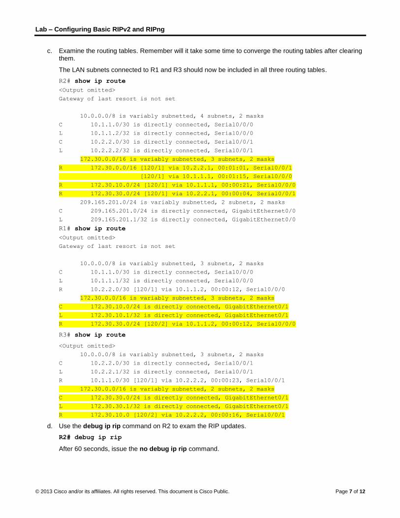
Lab – Configuring Basic RIPv2 and RIPng
© 2013 Cisco and/or its affiliates. All rights reserved. This document is Cisco Public. Page 7 of 12
c. Examine the routing tables. Remember will it take some time to converge the routing tables after clearing them.
The LAN subnets connected to R1 and R3 should now be included in all three routing tables.
R2# show ip route
<Output omitted>
Gateway of last resort is not set
10.0.0.0/8 is variably subnetted, 4 subnets, 2 masks
C 10.1.1.0/30 is directly connected, Serial0/0/0
L 10.1.1.2/32 is directly connected, Serial0/0/0
C 10.2.2.0/30 is directly connected, Serial0/0/1
L 10.2.2.2/32 is directly connected, Serial0/0/1
172.30.0.0/16 is variably subnetted, 3 subnets, 2 masks
R 172.30.0.0/16 [120/1] via 10.2.2.1, 00:01:01, Serial0/0/1
[120/1] via 10.1.1.1, 00:01:15, Serial0/0/0
R 172.30.10.0/24 [120/1] via 10.1.1.1, 00:00:21, Serial0/0/0
R 172.30.30.0/24 [120/1] via 10.2.2.1, 00:00:04, Serial0/0/1
209.165.201.0/24 is variably subnetted, 2 subnets, 2 masks
C 209.165.201.0/24 is directly connected, GigabitEthernet0/0
L 209.165.201.1/32 is directly connected, GigabitEthernet0/0
R1# show ip route
<Output omitted>
Gateway of last resort is not set
10.0.0.0/8 is variably subnetted, 3 subnets, 2 masks
C 10.1.1.0/30 is directly connected, Serial0/0/0
L 10.1.1.1/32 is directly connected, Serial0/0/0
R 10.2.2.0/30 [120/1] via 10.1.1.2, 00:00:12, Serial0/0/0
172.30.0.0/16 is variably subnetted, 3 subnets, 2 masks
C 172.30.10.0/24 is directly connected, GigabitEthernet0/1
L 172.30.10.1/32 is directly connected, GigabitEthernet0/1
R 172.30.30.0/24 [120/2] via 10.1.1.2, 00:00:12, Serial0/0/0
R3# show ip route
<Output omitted>
10.0.0.0/8 is variably subnetted, 3 subnets, 2 masks
C 10.2.2.0/30 is directly connected, Serial0/0/1
L 10.2.2.1/32 is directly connected, Serial0/0/1
R 10.1.1.0/30 [120/1] via 10.2.2.2, 00:00:23, Serial0/0/1
172.30.0.0/16 is variably subnetted, 2 subnets, 2 masks
C 172.30.30.0/24 is directly connected, GigabitEthernet0/1
L 172.30.30.1/32 is directly connected, GigabitEthernet0/1
R 172.30.10.0 [120/2] via 10.2.2.2, 00:00:16, Serial0/0/1
d. Use the debug ip rip command on R2 to exam the RIP updates.
R2# debug ip rip
After 60 seconds, issue the no debug ip rip command.

Lab – Configuring Basic RIPv2 and RIPng
© 2013 Cisco and/or its affiliates. All rights reserved. This document is Cisco Public. Page 8 of 12
What routes are in the RIP updates that are received from R3?
________________________________________________________________________________
Are the subnet masks now included in the routing updates? _________
Step 4: Configure and redistribute a default route for Internet access.
a. From R2, create a static route to network 0.0.0.0 0.0.0.0, using the ip route command. This forwards any unknown destination address traffic to the R2 G0/0 toward PC-B, simulating the Internet by setting a Gateway of Last Resort on the R2 router.
R2(config)# ip route 0.0.0.0 0.0.0.0 209.165.201.2
b. R2 will advertise a route to the other routers if the default-information originate command is added to its RIP configuration.
R2(config)# router rip
R2(config-router)# default-information originate
Step 5: Verify the routing configuration.
a. View the routing table on R1.
R1# show ip route
<Output omitted>
Gateway of last resort is 10.1.1.2 to network 0.0.0.0
R* 0.0.0.0/0 [120/1] via 10.1.1.2, 00:00:13, Serial0/0/0
10.0.0.0/8 is variably subnetted, 3 subnets, 2 masks
C 10.1.1.0/30 is directly connected, Serial0/0/0
L 10.1.1.1/32 is directly connected, Serial0/0/0
R 10.2.2.0/30 [120/1] via 10.1.1.2, 00:00:13, Serial0/0/0
172.30.0.0/16 is variably subnetted, 3 subnets, 2 masks
C 172.30.10.0/24 is directly connected, GigabitEthernet0/1
L 172.30.10.1/32 is directly connected, GigabitEthernet0/1
R 172.30.30.0/24 [120/2] via 10.1.1.2, 00:00:13, Serial0/0/0
How can you tell from the routing table that the subnetted network shared by R1 and R3 has a pathway for Internet traffic?
____________________________________________________________________________________
____________________________________________________________________________________
b. View the routing table on R2.
How is the pathway for Internet traffic provided in its routing table?
____________________________________________________________________________________
____________________________________________________________________________________
Step 6: Verify connectivity.
a. Simulate sending traffic to the Internet by pinging from PC-A and PC-C to 209.165.201.2.
Were the pings successful? ______

Lab – Configuring Basic RIPv2 and RIPng
© 2013 Cisco and/or its affiliates. All rights reserved. This document is Cisco Public. Page 9 of 12
b. Verify that hosts within the subnetted network can reach each other by pinging between PC-A and PC-C.
Were the pings successful? ______
Note: It may be necessary to disable the PCs firewall.
Part 3: Configure IPv6 on Devices
In Part 3, you will configure all interfaces with IPv6 addresses and verify connectivity.
Addressing Table
Device Interface IPv6 Address / Prefix Length Default Gateway
R1 G0/1 2001:DB8:ACAD:A::1/64
FE80::1 link-local N/A
S0/0/0 2001:DB8:ACAD:12::1/64
FE80::1 link-local N/A
R2 G0/0 2001:DB8:ACAD:B::2/64
FE80::2 link-local N/A
S0/0/0 2001:DB8:ACAD:12::2/64
FE80::2 link-local N/A
S0/0/1 2001:DB8:ACAD:23::2/64
FE80::2 link-local N/A
R3 G0/1 2001:DB8:ACAD:C::3/64
FE80::3 link-local N/A
S0/0/1 2001:DB8:ACAD:23::3/64
FE80::3 link-local N/A
PC-A NIC 2001:DB8:ACAD:A::A/64 FE80::1
PC-B NIC 2001:DB8:ACAD:B::B/64 FE80::2
PC-C NIC 2001:DB8:ACAD:C::C/64 FE80::3
Step 1: Configure PC hosts.
Refer to the Addressing Table for PC host address information.
Step 2: Configure IPv6 on routers.
Note: Assigning an IPv6 address in addition to an IPv4 address on an interface is known as dual stacking. This is because both IPv4 and IPv6 protocol stacks are active.
a. For each router interface, assign the global and link local address from the Addressing Table.
b. Enable IPv6 routing on each router.
c. Enter the appropriate command to verify IPv6 addresses and link status. Write the command in the space below.
____________________________________________________________________________________

Lab – Configuring Basic RIPv2 and RIPng
© 2013 Cisco and/or its affiliates. All rights reserved. This document is Cisco Public. Page 10 of 12
d. Each workstation should be able to ping the attached router. Verify and troubleshoot if necessary.
e. The routers should be able to ping one another. Verify and troubleshoot if necessary.
Part 4: Configure and Verify RIPng Routing
In Part 4, you will configure RIPng routing on all routers, verify that routing tables are updated correctly, configure and distribute a default route, and verify end-to-end connectivity.
Step 1: Configure RIPng routing.
With IPv6, it is common to have multiple IPv6 addresses configured on an interface. The network statement has been eliminated in RIPng. RIPng routing is enabled at the interface level instead, and is identified by a locally significant process name as multiple processes can be created with RIPng.
a. Issue the ipv6 rip Test1 enable command for each interface on R1 that is to participate in RIPng routing, where Test1 is the locally significant process name.
R1(config)# interface g0/1
R1(config)# ipv6 rip Test1 enable
R1(config)# interface s0/0/0
R1(config)# ipv6 rip Test1 enable
b. Configure RIPng for the serial interfaces on R2 with Test2 as the process name. Do not configure for the G0/0 interface.
c. Configure RIPng for each interface on R3 with Test3 as the process name.
d. Verify that RIPng is running on the routers.
The show ipv6 protocols, show run, show ipv6 rip database, and show ipv6 rip process name commands can all be used to confirm that RIPng is running. On R1, issue the show ipv6 protocols command.
R1# show ipv6 protocols
IPv6 Routing Protocol is "connected"
IPv6 Routing Protocol is "ND"
IPv6 Routing Protocol is "rip Test1"
Interfaces:
Serial0/0/0
GigabitEthernet0/1
Redistribution:
None
How is the RIPng listed in the output? _____________________________________________________
e. Issue the show ipv6 rip Test1 command.
R1# show ipv6 rip Test1
RIP process "Test1", port 521, multicast-group FF02::9, pid 314
Administrative distance is 120. Maximum paths is 16
Updates every 30 seconds, expire after 180
Holddown lasts 0 seconds, garbage collect after 120
Split horizon is on; poison reverse is off
Default routes are not generated
Periodic updates 1, trigger updates 0
Full Advertisement 0, Delayed Events 0
Interfaces:

Lab – Configuring Basic RIPv2 and RIPng
© 2013 Cisco and/or its affiliates. All rights reserved. This document is Cisco Public. Page 11 of 12
GigabitEthernet0/1
Serial0/0/0
Redistribution:
None
How are RIPv2 and RIPng similar?
____________________________________________________________________________________
____________________________________________________________________________________
f. Inspect the IPv6 routing table on each router. Write the appropriate command used to view the routing table in the space below.
____________________________________________________________________________________
On R1, how many routes have been learned by RIPng? _________
On R2, how many routes have been learned by RIPng? _________
On R3, how many routes have been learned by RIPng? _________
g. Check connectivity between PCs.
From PC-A, is it possible to ping PC-B? _________
From PC-A, is it possible to ping PC-C? _________
From PC-C, is it possible to ping PC-B? _________
From PC-C, is it possible to ping PC-A? _________
Why are some pings successful and others not?
____________________________________________________________________________________
Step 2: Configure and redistribute a default route.
a. From R2, create a static default route to network ::0/64 using the ipv6 route command, and the IPv6 address of PC-B. This forwards any unknown destination address traffic to the R2 G0/0 interface toward PC-B, simulating the Internet. Write the command used in the space below.
____________________________________________________________________________________
b. Static routes can be included in RIPng updates by using the ipv6 rip process name default-information originate command in interface configuration mode. Configure the serial links on R2 to send the default route in RIPng updates.
R2(config)# int s0/0/0
R2(config-rtr)# ipv6 rip Test2 default-information originate
R2(config)# int s0/0/1
R2(config-rtr)# ipv6 rip Test2 default-information originate
Step 3: Verify the routing configuration.
a. View the IPv6 routing table on R2.
R2# show ipv6 route
IPv6 Routing Table - 10 entries
Codes: C - Connected, L - Local, S - Static, R - RIP, B - BGP
U - Per-user Static route, M - MIPv6
I1 - ISIS L1, I2 - ISIS L2, IA - ISIS interarea, IS - ISIS summary
O - OSPF intra, OI - OSPF inter, OE1 - OSPF ext 1, OE2 - OSPF ext 2

Lab – Configuring Basic RIPv2 and RIPng
© 2013 Cisco and/or its affiliates. All rights reserved. This document is Cisco Public. Page 12 of 12
ON1 - OSPF NSSA ext 1, ON2 - OSPF NSSA ext 2
D - EIGRP, EX - EIGRP external
S ::/64 [1/0]
via 2001:DB8:ACAD:B::B
R 2001:DB8:ACAD:A::/64 [120/2]
via FE80::1, Serial0/0/0
C 2001:DB8:ACAD:B::/64 [0/0]
via ::, GigabitEthernet0/1
L 2001:DB8:ACAD:B::2/128 [0/0]
via ::, GigabitEthernet0/1
R 2001:DB8:ACAD:C::/64 [120/2]
via FE80::3, Serial0/0/1
C 2001:DB8:ACAD:12::/64 [0/0]
via ::, Serial0/0/0
L 2001:DB8:ACAD:12::2/128 [0/0]
via ::, Serial0/0/0
C 2001:DB8:ACAD:23::/64 [0/0]
via ::, Serial0/0/1
L 2001:DB8:ACAD:23::2/128 [0/0]
via ::, Serial0/0/1
L FF00::/8 [0/0]
via ::, Null0
How can you tell from the routing table that R2 has a pathway for Internet traffic?
________________________________________________________________________________
b. View the routing tables on R1 and R3.
How is the pathway for Internet traffic provided in their routing tables?
________________________________________________________________________________
Step 4: Verify connectivity.
Simulate sending traffic to the Internet by pinging from PC-A and PC-C to 2001:DB8:ACAD:B::B/64.
Were the pings successful? ______
Reflection
1. Why would you turn off automatic summarization for RIPv2?
_______________________________________________________________________________________
2. In both scenarios, how did R1 and R3 learn the pathway to the Internet? _______________________________________________________________________________________
3. How are configuring RIPv2 and RIPng different?
_______________________________________________________________________________________
_______________________________________________________________________________________