
CCI DRAG DA-90DSV Attemperator/media/Files/C/CCI/pdf/880.pdfin Heat Recovery Steam Generators ......
8
CCI DRAG ® DA-90DSV Attemperator
Transcript of CCI DRAG DA-90DSV Attemperator/media/Files/C/CCI/pdf/880.pdfin Heat Recovery Steam Generators ......

CCI DRAG®
DA-90DSV Attemperator
CC
I D
RA
G®
DA
-90
DS
V A
ttem
per
ator
DA-90DSV Attemperator application discussion
� Minimizes Leakage
� Handles High Thermal Stresses
� Enhances Controllability
� Prevents Cavitation Damage
� Meets Common Face-to-face Dimensions
� Lowers Maintenance Costs
� Reduces Erosion Damage
� Increases Plant Efficiency
Figure 1: Typical HRSG schematic
With each new operating season, the limits of inter-stage attemperators
in Heat Recovery Steam Generators (HRSG’s) are being tested. As plants
search for the most economical operation, be it cycling daily or operating
at reduced loads for extended hours, reliability and operability of the
superheat (SH) and reheat (RH) inter-stage attemperators consistently
come into question. Whether it is a constantly leaking attemperator
that must be repaired or replaced every outage, or a more catastrophic
failure like a boiler tube leak or a ruptured steam line, the headaches and
frustrations associated with inter-stage attemperation are becoming all
too familiar to plant managers, operators, and maintenance personnel.
2
Flash Vessel
Spraywater
DA-90 DSV SH-InterstageAttemperator
Economizer
Reheater
Reheater
Superheater
Superheater
Steam Generator
Boiler
DA-90DSV RH-InterstageAttemperator
Spraywater
IP/LP Turbine
HP Turbine
HRSG
From HPTurbine Exhaust
600
700
800
900
1000
1100
0 5 10 15 20 25 30
Time, minutes
Tem
pera
ture
, deg
F
0
10
20
30
40
50
Spra
ywat
er fl
ow, k
pph
SH1 outlet SH2 inlet Final steam Spraywater flow
600
700
800
900
1000
1100
0 5 10 15 20 25 30
Time, minutes
Tem
pera
ture
, deg
F
0
10
20
30
40
50
Spra
ywat
er fl
ow, k
pph
SH1 outlet SH2 inlet Final steam Spraywater flow
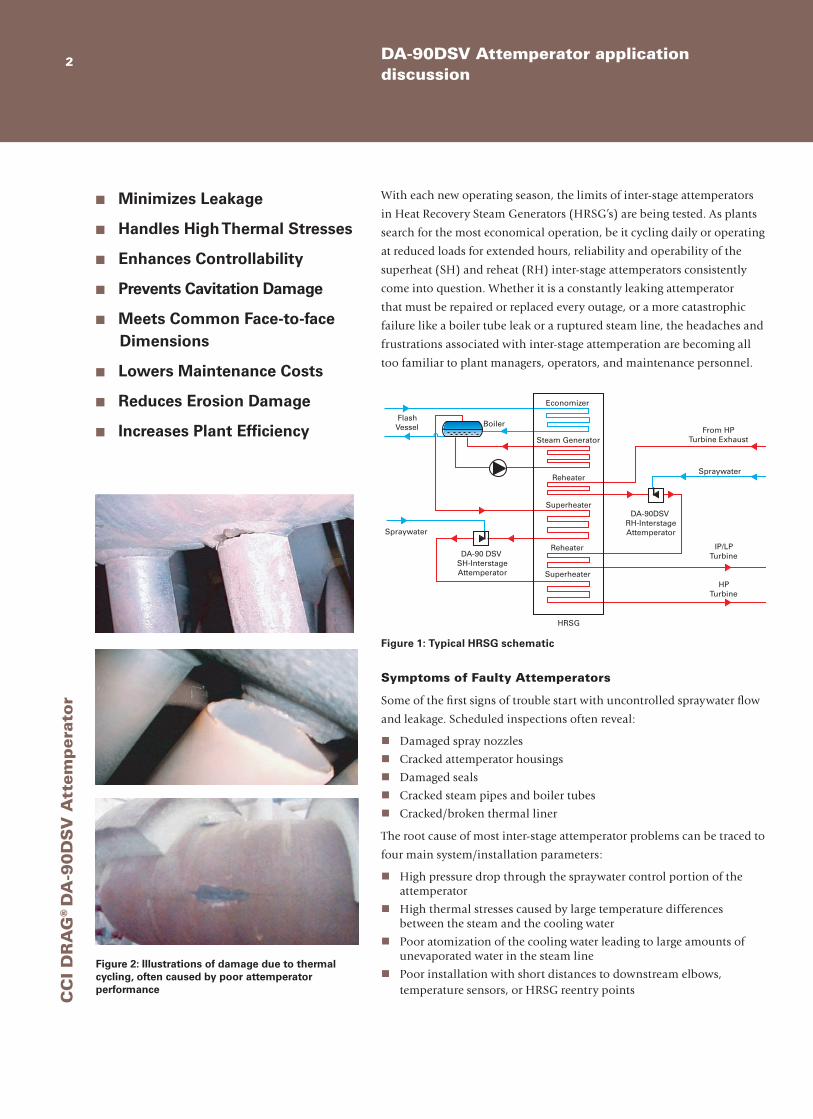
Figure 2: Illustrations of damage due to thermal cycling, often caused by poor attemperator performance
Symptoms of Faulty Attemperators
Some of the first signs of trouble start with uncontrolled spraywater flow
and leakage. Scheduled inspections often reveal:
nDamaged spray nozzles
nCracked attemperator housings
nDamaged seals
nCracked steam pipes and boiler tubes
nCracked/broken thermal liner
The root cause of most inter-stage attemperator problems can be traced to
four main system/installation parameters:
nHigh pressure drop through the spraywater control portion of the attemperator
nHigh thermal stresses caused by large temperature differences between the steam and the cooling water
nPoor atomization of the cooling water leading to large amounts of unevaporated water in the steam line
nPoor installation with short distances to downstream elbows, temperature sensors, or HRSG reentry points
600
700
800
900
1000
1100
0 5 10 15 20 25 30
Time, minutes
Tem
pera
ture
, deg
F
0
10
20
30
40
50
Spra
ywat
er fl
ow, k
pph
SH1 outlet SH2 inlet Final steam Spraywater flow

C
CI D
RA
G®
DA
-90
DS
V A
ttemp
erator
3DRAG® DA-90DSV Attemperator
Faulty Attemperator Design
Many of the common interstage attemperator systems overlook several or
all of the root causes of failure listed on the previous page. Such designs
will lead to problems in your plant, it’s only a matter of time! Consider
the following:
Single Stage Pressure Drop – Problem
When using fixed speed pumps, the pressure drop in some inter-stage
attemperator spraywater systems can reach levels greater than 2000 psi
(133 bar). This high pressure drop will severely damage and prematurely
wear a single stage control element causing wire draw, leakage, and
cavitation damage (See Figure 3). The key to eliminating this root cause
of failure is to incorporate multiple stages of pressure drop in a control
valve trim. CCI’s DRAG® Velocity Control Trim can easily package up to
20 stages of pressure drop in attemperator systems to handle the large
pressure drop of the spraywater system.
Valve Trim in the Steam Flow – Problem
As allowable operating temperatures increase, inter-stage attemperators
can see steam to spraywater temperature differences near 700ºF (390ºC).
This high temperature difference in conventional attemperator designs
will lead to high thermal stresses. An attemperator design, such as the
one shown in Figure 4, that locates tight clearance control elements (i.e.
valve trim) in an environment that sees these drastic temperature swings
will fail. Common failures such as cracked attemperator bodies, cracked
attemperator welds, cracked attemperator nozzles, stuck or seized plug
and stem elements, and even packing leaks can all be attributed to a
design that neglects to account for the high temperature difference in this
application. To avoid these problems, location is the key. Tight clearance
valve trim components should be moved out of the steam pipe and away
from the hot steam temperatures.
Pressure Boundary and Tack Welds – Problem
Due to the nature of the application and the operation of today’s HRSGs,
interstage attemperators will always be exposed to thermal cycling. Welds,
and the heat affected zones around them, are vulnerable to cracking when
put through thermal cycles while also being exposed to high pressure
loads and bending stresses. A properly designed interstage attemperator
eliminates all welds by using a one-piece Chrome Moly forging, thus
removing the risk of cracking in the attemperator body.
Problems Solution
High pressure drop in a single stage Use multiple stages of pressure drop in a DRAG® Velocity Control Trim
Expose attemperator to high thermal stresses by locating trim components in the hot steam pipe
Move the valve trim to a safer environment outside of the steam pipe and away from harsh thermal stresses
Use pressure boundary welds and tack welds Eliminate all welds by using a one-piece Chrome Moly forging
Figure 3: Cavitation damage on plug
Figure 4: Section view of a conventional attemperator design

CC
I D
RA
G®
DA
-90
DS
V A
ttem
per
ator
DRAG® DA-90DSV Attemperator features4
Benefits DRAG™
DA-90DSV Competition
n Provides the Valve Doctor Solution. CCI works with plant operators to improve plant performance, reliability and output.
n Prevents Cavitation Damage. CCI works in accordance with ISA guidelines to ensure cavitation is avoided.
n Eliminates Erosion Damage. By controlling fluid velocities, erosion is eliminated.
Multi-stage DRAG® Disk Stack Technologies
Limits fluid velocities, controls vibration and erosion. Multiple Cv disks throughout disk stack allow for characterized design
with optimum control throughout all operating conditions
Stem Packing
Graphite packing is standard for high temperature service
Water Inlet
Customer Connections
Class V Shut-off
A metal seat is standard, with a
500 PLI (9 kg/mm) loading force to
achieve tight shut-off
Disk Stack Labyrinth
Grooves
This section of the disk stack
has no flow passages; in
their place labyrinth
grooves break up clearance
flow, preventing seat ring damage

C
CI D
RA
G®
DA
-90
DS
V A
ttemp
erator
Use check list to evaluate the benefits of CCI’s DRAG™ DA-90DSV Attemperator 5
Spray Nozzle
The variable orifice spray nozzle used in the DA-90DSV provides excellent primary atomization and high rangeability. The design is proven through decades of installation in high temperature steam applications. Multiple nozzle designs (as pictured) are available for high capacity installations
n Thermal Stress Analysis. CCI accounts for all thermal stresses in the attemperator design.
n Stops Costly Maintenance Cycles. CCI valves are designed
and sized to provide longer intervals between maintenance and allow easy access to all components.
n Eliminate Thermal Damage to the Trim. Control element is located outside of the hot steam flow.
n Proven Desuperheating Experience.
Benefits DRAG™
DA-90DSV Competition
No Trim in Steam Flow
Many probe designs place valve trims in the steam flow, exposing them to high steam temperatures
and very large thermal stresses. The DA-90DSV moves all tight
clearance trim components out of the steam flow and out of the
harmful thermal environment
Tapered Profile
The attemperator is designed with a tapered profile to minimize any
vibrations caused by harmonic frequencies associated with
vortex shedding. This becomes especially important as pipe sizes
increase and the length of the attemperator increases
Forged Design
A fully forged one-piece Chrome Moly design eliminates the need
for welding, and eliminates the risk of welds failing due to the
high thermal cycling and stress of the surrounding environment
LowFlow
HighFlow

CC
I D
RA
G®
DA
-90
DS
V A
ttem
per
ator
6 DA-90DSV Attemperator Solutions
Figure 6: Characterized Equal Percentage DRAG® disk stack trim
% Flow1009080706050403020100
0 10 20 30 40 50 60 70 80 90 100
% Stroke
Modified Linear
Linear
Modified Equal %
Eliminate Cavitation with DRAG®
DRAG® trim forces the fluid to travel through a torturous path of turns
(Figure 5). Each turn causes a pressure loss in the fluid, and the pressure
gradually reduces as the fluid flows through the multiple turns. This
series of multiple pressure drops controls the fluid velocity and allows
the pressure to reduce without falling below the vapor pressure, thus
avoiding cavitation and the destruction to the valve and trim that can
come with it. The DRAG® multistage pressure drop trim provides a clear
benefit in terms of performance and maintenance costs when cavitation is
a concern.
Accurate Control and Reliable Operation at all Flow Conditions with the CCI DRAG® Disk Stack
DRAG® disk stacks can be customized to provide the required Cv
throughout the valve stroke. This is accomplished by configuring disks
with various numbers of turns within the stack (Figure 6). Thus, the
DRAG® control valve disk stack can be designed for many different flow
characteristics, i.e. linear, equal percentage, or modified equal percentage
(Figure 6). The disks at the bottom of the disk stack, close to the valve
seat, are equipped with a higher number of pressure letdown stages (up to
20 stages or more) to provide critical protection of the seating surfaces on
the plug and seat ring. As the valve strokes open, fewer pressure letdown
stages are used for more capacity as the process requires, providing
good control over the entire range of flow conditions. Independent and
isolated flow paths are used to eliminate short circuits between flow paths
and provide the best result in pressure letdown.
Reliable Long Term Shutoff
The DRAG® control valve uses a hard seat material and a very high seat
loading to provide reliable and repeatable long term shutoff in very high
pressure differential applications. The actuator is sized to provide a
minimum seating load of 500 lb/in (9 kg/mm) of seat ring circumference,
as recommended by ISA guidelines. The DRAG® velocity control trim
design, combined with the high seating force for shut-off, protects the
seating surfaces from cutting and pitting due to erosion or wire draw.
Benefits of DRAG® Velocity Control Trim
n Prevents Cavitation Damage
n Improves Plant Performance
n Eliminates Erosion Damage
n Lowers Operating Costs
n Reduces Maintenance Costs
n Reduces System Complexity
n Avoids Plant Shutdowns
n Provides Accurate Temperature Control
Figure 5: Each turn in the DRAG® trim is a single stage of pressure drop, eliminating potentially harmful kinetic energy
Multiple Inlet Flow Channels
Pressure Equalizing Ring (PER) Grooves

C
CI D
RA
G®
DA
-90
DS
V A
ttemp
erator
6” (153mm) MIN C
STEAM CONNECTION
WATER INLET
HEIGHT
B
A
7Technical Specifications
No Name Material
1 Body ASME-SA217-WC9/C12A
2 Bonnet ASME-SA182-F22/F91
3 Spindle INCONEL 718
4 Guide Bushing 300 SS
5 Gaskets Graphite/300 SS
6 Seat 300 SS
7 Disk Stack INCONEL 718
8 Packing, Stem Graphite
9 Packing, Spacer Carbon
10 Yoke Carbon Steel
11 Nozzle Housing ASME-SA182-F22/F91
12 Spray Nozzle ANSI 616
7
6
4
5
3
59
8
10 2
1
12
11
MIN BORE, D
Trim SizeWater Flange
Steam Flange
ANSI A B CDia. D(4) Height (2) Weight
3/8”, 5/8”, 1” (10, 15, 25)
1.5” RF (40)
3.0” RF (80)
600-15009.0” (229)
6.0” (152)
19.7” (500)
2.9” (73.7)
34” (865)
~300 lbs (140 kg)
25009.5” (241)
7.0” (178)
1.5” (40)
2.5” RF (65)
4.0” RF (100)
600-250012.25” (311.2)
12.25” (276.4)
3.81” (96.8)
51” (1295)
~500 lbs (230 kg)
Nom. Pipe Dia.Length
(see note 3 & 6)
10-14”(250-350) 14.12”(358.6)
16-20”(400-500) 17.75”(450.8)>20” (>500) 21.25” (539.8)
Notes:1. Contact factory for other sizes2. Given is maximum; add 15” (380 mm) for manual override3. Customer flange height will vary to center nozzle(s) in steam pipe4. Customer supplied flanged connection5. Numbers in brackets give dimensions in millimeters6. Custom probe lengths available for retrofit projects

DRAG is a registered trademark of CCI.©2007 CCI 880 05/11/07
Throughout the world, companies rely on CCI to solve their severe service control valve problems. CCI has provided custom solutions for these and other industry applications for nearly half a century.
CCI AustraliaPhone: 61 2 9918 409421 Catalina Crescent Avalon, NSW 2107 Australia
CCI Austria(Formerly Spectris Components GmbH)
Phone: 43 1 869 27 40Fax: 43 1 865 36 03Lembockgasse 63/1AT-1233 ViennaAustria
CCI China - Beijing Phone: 86 10 6501 0350Fax: 86 10 6501 0286Fortune Plaza, 7 Dong San Huan Zhong Room 606 Office Tower Chao Yang District 100020Beijing China
CCI China – ShanghaiPhone: 0086 21 64851331Fax: 0086 21 64851328Room 1003-1004 Xinyuan Technology TowerNo. 418 Guiping RoadShanghai 200233China
CCI Houston (Repair Center)Phone: 713 869 52333409 BrinkmanHouston, TX 77018USA
CCI IndiaPhone: 0091 80 4030 3500SJR iPark, 6th Floor, Warp TowerPlot No. 13, 14 & 15, EPIP ZonePhase 1, Whitefield RoadBangalore EastBangalore 560 066India
CCI sales offices worldwide.
CCI Italy - FlorencePhone: 39 0571 5953203Via Dell’Industria 13 50056 Montelupo Fiorentino (Fl) Italy
CCI Italy – MilanPhone: 39 02 4671 2274Via Vincenzo Monti 8 20123 MilanoItaly
CCI KK – Kobe CityPhone: 81 78 991 5910 6-2-2 Takatsukadai, Nishi-ku Kobe City Hyogo 651-2271 Japan
CCI Japan - TokyoPhone: 81 3 5402 31004th Floor Terada Bldg. 2-3-3 Shibakoen Minato-ku, Tokyo 105-0011 Japan
CCI Korea – SeoulPhone: 82 (0)31 980 996010F, Sinwon B/D, 210-1, Hangangno-2GA Yongsan-Gu Seoul Korea
CCI Korea – Gimpo CityPhone: 82 31 980 9800# 26-17, Pungmu-DongGimpo-Si, Gyeonggi-DoKorea
CCI Middle East - DubaiPhone: 9714 886 1477Light Industrial Unit: BJ04 Jebel Ali Free Zone, Dubai FZS1 UAE
Contact us at:[email protected]
Visit us online for sales and service locations at: www.ccivalve.com
Nuclear
Oil & Gas
Fossil Fuel
CHP
CCI RSM – World HeadquartersPhone: 949 858 1877Fax: 949 858 187822591 Avenida EmpresaRancho Santa Margarita, CA 92688USA
CCI RussiaPhone: 7 495 941 8660Europe Square 2, Office 611 Moscow 121059 Russia
CCI South AfricaPhone: 27 13 690 3305Shop 4, 14 Arnhem Singel Die Heuwel Witbank 1035 South Africa
CCI Sweden(Formerly BTG Valves)
Phone: 46 533 689 600Fax: 46 533 689 601Industrigatan 1-3, Box 603 SE-661 29 Saffle Sweden
CCI Switzerland(Formerly Sulzer Valves)
Phone: 41 52 264 95 00Fax: 41 52 264 95 01lm Link 11, P.O. Box 65 8404, Winterthur Switzerland
CCI Technology Centre – UKPhone: 44 (0) 161 655 1690Unit A3, Brookside Business Park Greengate, MiddletonManchester M24 1GS UK