CBSE Board-XII Physics Paper+Sol. 05-03-2016 - Career...
30
1 / 30 PHYSICS CBSE-XII-2016 EXAMINATION CAREER POINT, CP Tower, Road No.1, IPIA, Kota (Raj.), Ph: 0744-5151200 Website : www.careerpoint.ac.in, Email: [email protected] CAREER POINT PHYSICS Paper & Solution Time : 3 Hrs. Max. Marks : 70 General Instruction : (i) All questions are compulsory. There are 26 questions in all. (ii) This question paper has five sections : Section A, Section B, Section C, Section D, Section E. (iii) Section A contain five questions of one mark each. Section B contains five questions of two marks each, Section C contains twelve questions of three marks each, Section D contains one value based question of four marks and Section E contains three questions of five marks each. (iv) There is no overall choice. However, an internal choice has been provided in one question of two marks, one question of three marks and all the three questions of five marks weightage. You have to attempt only one of the choices in such questions. (v) You may use the following values of physical constants wherever necessary : c = 3 × 10 8 m/s h = 6.63 × 10 –34 Js e = 1.6 × 10 –19 C µ 0 = 4π × 10 –7 T mA –1 ε 0 = 8.854 × 10 –12 C 2 N –1 m –2 0 4 1 πε = 9 × 10 9 N m 2 C –2 m e = 9.1 × 10 –31 kg Mass of Neutrons = 1.675 × 10 –27 kg Mass of proton = 1.673 × 10 –27 kg Avogadro's number = 6.023 × 10 23 per gram mole Boltzmann constant = 1.38 × 10 –23 JK –1 SECTION-A 1. Why can't we see clearly through fog ? Name the phenomenon responsible for it. [1] Sol. Due to scattering phenomenon, we can't see clearly through fog. 2. What is the amount of work done in moving a point charge Q around a circular arc of radius 'r' at the centre of which another point charge 'q' is located ? [1] Sol. Students may find similar question in CP exercise sheet: [JEE Main, Chapter : Electrostatics, Level # 1, Q.71] Circular arc r B A q Q A Charge partical of charge Q moving on circular arc where at the centre the charge q is located. Work done by electrostatic force on moving charge Q W field = –∆U (Where ∆U is change in potential energy) U A = qV A U B = qV B here V A = V B = r kq W field = – (U B – U A ) [So U A – U B ] W field = 0 Code : 55/2/N
Transcript of CBSE Board-XII Physics Paper+Sol. 05-03-2016 - Career...

1 / 30
PHYSICS CBSE-XII-2016 EXAMINATION
CAREER POINT, CP Tower, Road No.1, IPIA, Kota (Raj.), Ph: 0744-5151200 Website : www.careerpoint.ac.in, Email: [email protected]
CAREER POINT
PHYSICS Paper & Solution
Time : 3 Hrs. Max. Marks : 70 General Instruction : (i) All questions are compulsory. There are 26 questions in all. (ii) This question paper has five sections : Section A, Section B, Section C, Section D, Section E. (iii) Section A contain five questions of one mark each. Section B contains five questions of two marks each,
Section C contains twelve questions of three marks each, Section D contains one value based question of four marks and Section E contains three questions of five marks each.
(iv) There is no overall choice. However, an internal choice has been provided in one question of two marks, one question of three marks and all the three questions of five marks weightage. You have to attempt only one of the choices in such questions.
(v) You may use the following values of physical constants wherever necessary : c = 3 × 10⁸ m/s h = 6.63 × 10⁻³⁴ Js e = 1.6 × 10⁻¹⁹ C µ0 = 4π × 10–7 T mA–1
ε0 = 8.854 × 10⁻¹² C2N–1m–2
04
1πε
= 9 × 10⁹ N m2 C–2
me = 9.1 × 10⁻³¹ kg Mass of Neutrons = 1.675 × 10⁻²⁷ kg Mass of proton = 1.673 × 10⁻²⁷ kg Avogadro's number = 6.023 × 10²³ per gram mole Boltzmann constant = 1.38 × 10⁻²³ JK–1
SECTION-A 1. Why can't we see clearly through fog ? Name the phenomenon responsible for it. [1] Sol. Due to scattering phenomenon, we can't see clearly through fog. 2. What is the amount of work done in moving a point charge Q around a circular arc of radius 'r' at the centre
of which another point charge 'q' is located ? [1] Sol. Students may find similar question in CP exercise sheet:
[JEE Main, Chapter : Electrostatics, Level # 1, Q.71]
Circular arc
r
B A
q
Q
A Charge partical of charge Q moving on circular arc where at the centre the charge q is located. Work done by electrostatic force on moving charge Q Wfield = –∆U (Where ∆U is change in potential energy) UA = qVA
UB = qVB here VA = VB = r
kq
Wfield = – (UB – UA) [So UA – UB] Wfield = 0
Code : 55/2/N
2 / 30
PHYSICS CBSE-XII-2016 EXAMINATION
CAREER POINT, CP Tower, Road No.1, IPIA, Kota (Raj.), Ph: 0744-5151200 Website : www.careerpoint.ac.in, Email: [email protected]
CAREER POINT
3. A signal of 5 kHz frequency is amplitude modulated on a carrier wave of frequency 2 MHz. What are the frequencies of the side bands produced ? [1]
Sol. Given frequency of carrier wave fc = 2 MHz = 2 × 10³ kHz Frequency of modulating signal fm = 5 kHz Frequency of lower side band (LSB) = fc – fm LSB = (2 × 10³ – 5)kHz LSB = (1995) kHz Frequency of upper side band (USB) = fc + fm USB = (2 × 10³ + 5)kHz USB = 2005kHz 4. What can be the cause of helical motion of a charged particle ? [1] Sol. When charge particle is projected in a uniform magnetic field in such a way that angle between velocity and
magnetic field is neither 90º nor 0 or 180º then charge particle move on helical path. 5. Define mobility of a charge carrier. What is its relation with relaxation time ? [1] Sol. Students may find similar question in CP exercise sheet: [JEE Main, Chapter : Current Electricity, Page No. 40, Q.26]
Mobility of a charge carriers is defined as the drift velocity of the charge carrier per unit electric field i.e.
µ = Evd =
meτ
SECTION-B
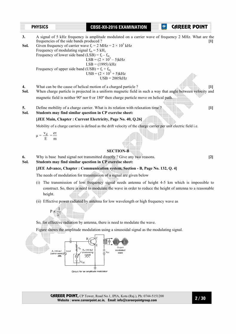
6. Why is base band signal not transmitted directly ? Give any two reasons. [2] Sol. Students may find similar question in CP exercise sheet: [JEE Advance, Chapter : Communication system, Section - B, Page No. 132, Q. 4]
The needs of modulation for transmission of a signal are given below
(i) The transmission of low frequency signal needs antenna of height 4-5 km which is impossible to construct. So, there is need to modulate the wave in order to reduce the height of antenna to a reasonable height.
(ii) Effective power radiated by antenna for low wavelength or high frequency wave as
P ∝ 21λ
So, for effective radiation by antenna, there is need to modulate the wave.
Figure shows the amplitude modulation using a sinusoidal signal as the modulating signal.
B C
E
VBE
3 / 30
PHYSICS CBSE-XII-2016 EXAMINATION
CAREER POINT, CP Tower, Road No.1, IPIA, Kota (Raj.), Ph: 0744-5151200 Website : www.careerpoint.ac.in, Email: [email protected]
CAREER POINT
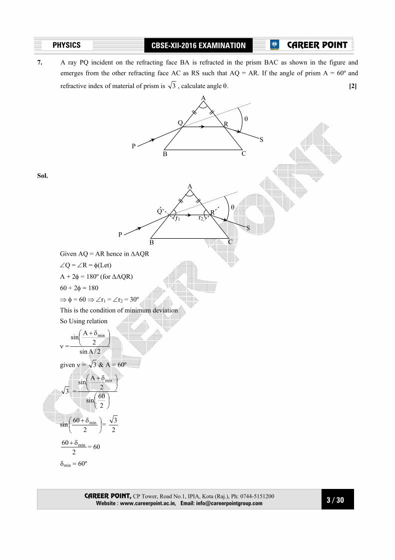
7. A ray PQ incident on the refracting face BA is refracted in the prism BAC as shown in the figure and emerges from the other refracting face AC as RS such that AQ = AR. If the angle of prism A = 60º and
refractive index of material of prism is 3 , calculate angle θ. [2]
A
Q
PB C
S
θ R
Sol.
A
Q
PB C
S
θ R
r1 r2
Given AQ = AR hence in ∆AQR
∠Q = ∠R = φ(Let)
A + 2φ = 180º (for ∆AQR)
60 + 2φ = 180
⇒ φ = 60 ⇒ ∠r1 = ∠r2 = 30º This is the condition of minimum deviation So Using relation
ν =2/Asin
2Asin min
δ+
given ν = 3 & A = 60º
3 =
δ+
260sin
2Asin min
sin
δ+
260 min =
23
2
60 minδ+ = 60
δmin = 60º
4 / 30
PHYSICS CBSE-XII-2016 EXAMINATION
CAREER POINT, CP Tower, Road No.1, IPIA, Kota (Raj.), Ph: 0744-5151200 Website : www.careerpoint.ac.in, Email: [email protected]
CAREER POINT
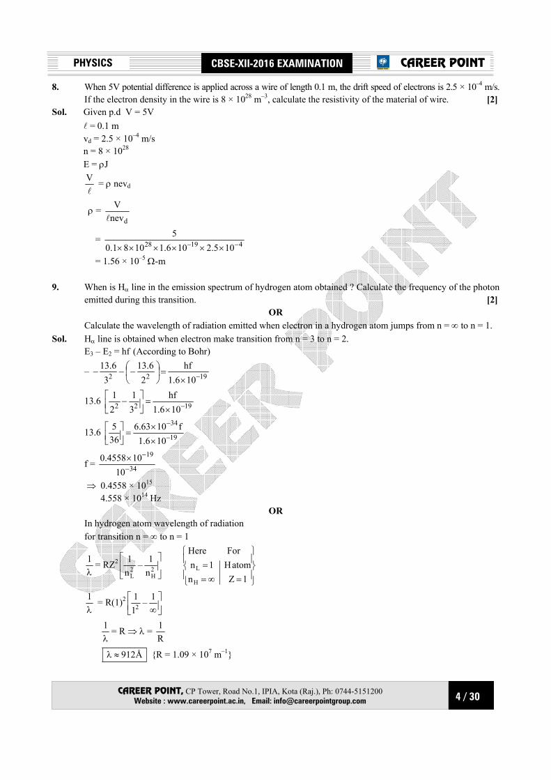
8. When 5V potential difference is applied across a wire of length 0.1 m, the drift speed of electrons is 2.5 × 10⁻⁴ m/s. If the electron density in the wire is 8 × 1028 m–3, calculate the resistivity of the material of wire. [2]
Sol. Given p.d V = 5V l = 0.1 m vd = 2.5 × 10⁻⁴ m/s n = 8 × 1028 E = ρJ
l
V = ρ nevd
ρ = dnev
Vl
= 41928 105.2106.11081.05
−− ××××××
= 1.56 × 10⁻⁵ Ω-m 9. When is Hα line in the emission spectrum of hydrogen atom obtained ? Calculate the frequency of the photon
emitted during this transition. [2] OR
Calculate the wavelength of radiation emitted when electron in a hydrogen atom jumps from n = ∞ to n = 1. Sol. Hα line is obtained when electron make transition from n = 3 to n = 2. E3 – E2 = hf (According to Bohr)
– 1922 106.1hf
26.13
36.13
−×=
−−−
13.6 1922 106.1hf
31
21
−×=
−
13.6 19
34
106.1f1063.6
365
−
−
××
=
f = 34
19
10104558.0
−
−×
⇒ 0.4558 × 10¹⁵ 4.558 × 10¹⁴ Hz
OR In hydrogen atom wavelength of radiation for transition n = ∞ to n = 1
λ1 = RZ2
2H
2L n
1–n1
=∞==
1ZnatomH1n
ForHere
H
L
λ1 = R(1)2
∞1–
112
λ1 = R ⇒ λ =
R1
Å912≈λ R = 1.09 × 10⁷ m–1

5 / 30
PHYSICS CBSE-XII-2016 EXAMINATION
CAREER POINT, CP Tower, Road No.1, IPIA, Kota (Raj.), Ph: 0744-5151200 Website : www.careerpoint.ac.in, Email: [email protected]
CAREER POINT
10. A proton and an α particle are accelerated through the same potential difference. Which one of the two has (i) greater de-Broblie wavelength, and (ii) less kinetic energy ? Justify your answer. [2]
Sol. When a charge particle is accelerated through V potential difference then its kinetic energy K.E. = qV (q = charge; V = potential difference) Proton and α-particle accelerated through same potential difference so because qα > qproton (qα = +2e and qproton = +e) K.Eα > K.Eproton
their Debroglie wavelength mqV2h
=λ
V = same mαqα > mpqp [mα = 4 mp] So λα < λp (λα = Debroglie wavelength of α-particle; λp = Debroglie wavelength of proton) Ans. (1) Proton have greater Debroglie wavelength (2) Proton have lesser kinetic energy
SECTION-C 11. State two important properties of photon which are used to write Einstein's photoelectric equation. Define
(i) stopping potential and (ii) threshold frequency, using Einstein's equation and drawing necessary plot between relevant quantities.
[3] Sol. Characteristic properties of photons : (i) Energy of photon is directly proportional to the frequency (or inversely proportional to the wavelength). (ii) In photon-electron collision, total energy and momentum of the system of two constituents remains
constant. (iii) In the interaction of photons with the free electrons, the entire energy of photon is absorbed. Cut off or stopping potential is that minimum value of negative potential at anode which just stops the
photo electric current For a given material, there is a minimum frequency of light frequency is called as threshold frequency. By Einstein's photo electric equation
KEmax = λ
hC – φ0 = hν – hν0 where φ0 = hν0
eV0 = hν – hν0
V0 = 0eh
eh
ν−ν
–φ0/e
V0
Slope=eh
ν0 ν
6 / 30
PHYSICS CBSE-XII-2016 EXAMINATION
CAREER POINT, CP Tower, Road No.1, IPIA, Kota (Raj.), Ph: 0744-5151200 Website : www.careerpoint.ac.in, Email: [email protected]
CAREER POINT
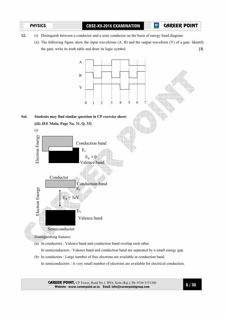
12. (i) Distinguish between a conductor and a semi conductor on the basis of energy band diagram.
(ii) The following figure show the input waveforms (A, B) and the output waveform (Y) of a gate. Identify
the gate, write its truth table and draw its logic symbol. [3]
0 1 2 3 4 5 6 7
A
B
Y
Sol. Students may find similar question in CP exercise sheet:
[(ii) JEE Main, Page No. 31, Q. 33]
(i)
Conduction bandEv
Eg ~= 0Valence bandEl
ectro
n En
ergy
Conduction bandEC
Conductor
Eg < 3eV
Valence band
EV
Semiconductor
Elec
tron
Ener
gy
Distinguishing features
(a) In conductors : Valence band and conduction band overlap each other.
In semiconductors : Valence band and conduction band are separated by a small energy gap.
(b) In conductors : Large number of free electrons are available in conduction band.
In semiconductors : A very small number of electrons are available for electrical conduction.

7 / 30
PHYSICS CBSE-XII-2016 EXAMINATION
CAREER POINT, CP Tower, Road No.1, IPIA, Kota (Raj.), Ph: 0744-5151200 Website : www.careerpoint.ac.in, Email: [email protected]
CAREER POINT
(ii) Gate From the given output waveform, it is clear that output is zero only when both inputs are 1, so the gate is NAND gate
A B Y 0 0 1 0 1 1 1 0 1 1 1 0
Logic symbol
YAB
Y = BA ⋅ 13. (a) Derive the mathematical expression for law of radioactive decay for a sample of a radioactive nucleus. (b) How is the mean life of a given radioactive nucleus related to the decay constant ? [3] Sol. (a) Radioactive decay Law : The rate of decay of radioactive nuclei is directly proportional to the number of
undecayed nuclei at that time. Derivation of formula Suppose initially the number of atoms in radioactive element is N0 and N the number of atoms after time t.
After time t, let dN be the number of atoms which disintegrate in a short interval dt, then rate of
disintegration will be dtdN , this is also called the activity of the substance/element.
According to Rutherford-Soddy law
dtdN ∝ N
or dtdN = –λN ....(i)
where λ is a constant, called decay constant or disintegration constant of the element. Its unit is s–1. Negative sign shows that the rate of disintegration decreases with increase of time. For a given element/substance λ is a constant and is different for different elements. Equation (i) may be rewritten as
N
dN = –λdt
Integrating logeN = –λt + C ....(ii) where C is a constant of integration. At t = 0, N = N0 ∴ logeN0 = 0 + C ⇒ C = logeN0 ∴ Equation (ii) gives logeN = –λt + logeN0 or logeN – logeN0 = –λt
or loge 0N
N = –λt
or 0N
N = e–λt
∴ N = N0e–λt ...(iii)
8 / 30
PHYSICS CBSE-XII-2016 EXAMINATION
CAREER POINT, CP Tower, Road No.1, IPIA, Kota (Raj.), Ph: 0744-5151200 Website : www.careerpoint.ac.in, Email: [email protected]
CAREER POINT
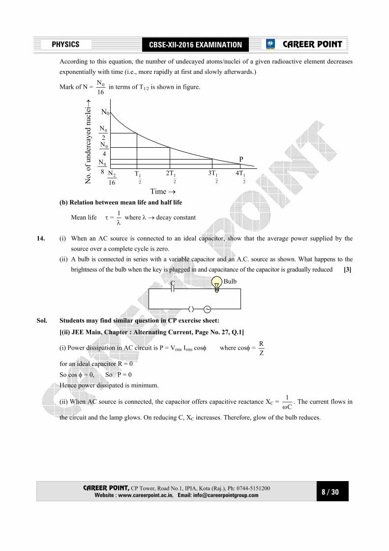
According to this equation, the number of undecayed atoms/nuclei of a given radioactive element decreases exponentially with time (i.e., more rapidly at first and slowly afterwards.)
Mark of N = 16N0 in terms of T1/2 is shown in figure.
16N2
21T
21T2
21T3
21T4
P
2N0
4N0
8N0
No.
of u
nder
caye
d nu
clei
→
Time →
N0
(b) Relation between mean life and half life
Mean life τ = λ1 where λ → decay constant
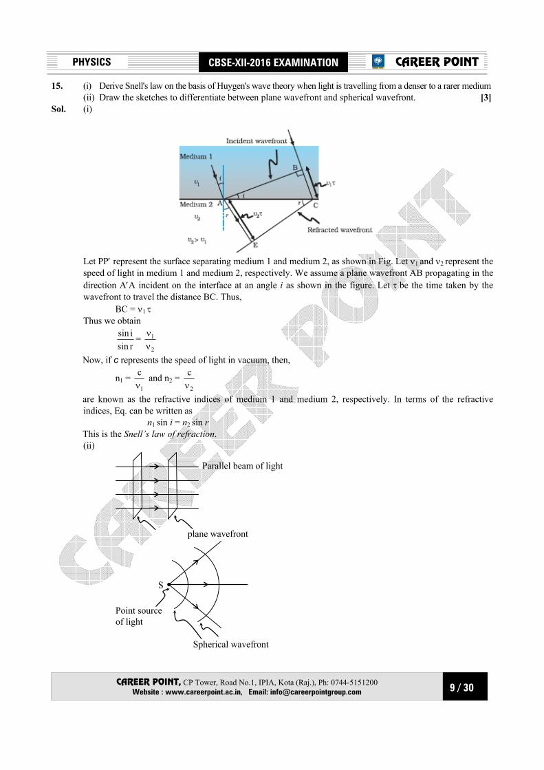
14. (i) When an AC source is connected to an ideal capacitor, show that the average power supplied by the source over a complete cycle is zero.
(ii) A bulb is connected in series with a variable capacitor and an A.C. source as shown. What happens to the brightness of the bulb when the key is plugged in and capacitance of the capacitor is gradually reduced [3]
~
BulbC
Sol. Students may find similar question in CP exercise sheet:
[(ii) JEE Main, Chapter : Alternating Current, Page No. 27, Q.1]
(i) Power dissipation in AC circuit is P = Vrms Irms cosφ where cosφ = ZR
for an ideal capacitor R = 0 So cos φ = 0, So P = 0 Hence power dissipated is minimum.
(ii) When AC source is connected, the capacitor offers capacitive reactance XC = C
1ω
. The current flows in
the circuit and the lamp glows. On reducing C, XC increases. Therefore, glow of the bulb reduces.
9 / 30
PHYSICS CBSE-XII-2016 EXAMINATION
CAREER POINT, CP Tower, Road No.1, IPIA, Kota (Raj.), Ph: 0744-5151200 Website : www.careerpoint.ac.in, Email: [email protected]
CAREER POINT
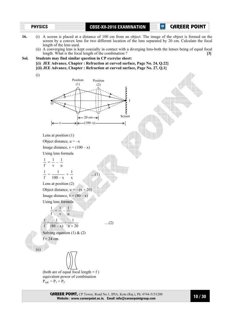
15. (i) Derive Snell's law on the basis of Huygen's wave theory when light is travelling from a denser to a rarer medium (ii) Draw the sketches to differentiate between plane wavefront and spherical wavefront. [3] Sol. (i)
Let PP′ represent the surface separating medium 1 and medium 2, as shown in Fig. Let ν1 and ν2 represent the
speed of light in medium 1 and medium 2, respectively. We assume a plane wavefront AB propagating in the direction A′A incident on the interface at an angle i as shown in the figure. Let τ be the time taken by the wavefront to travel the distance BC. Thus,
BC = ν1 τ Thus we obtain
rsinisin =
2
1
νν
Now, if c represents the speed of light in vacuum, then,
n1 = 1
cν
and n2 = 2
cν
are known as the refractive indices of medium 1 and medium 2, respectively. In terms of the refractive indices, Eq. can be written as
n1 sin i = n2 sin r This is the Snell’s law of refraction.
(ii)
Parallel beam of light
plane wavefront
Spherical wavefront
Point source of light
S
10 / 30
PHYSICS CBSE-XII-2016 EXAMINATION
CAREER POINT, CP Tower, Road No.1, IPIA, Kota (Raj.), Ph: 0744-5151200 Website : www.careerpoint.ac.in, Email: [email protected]
CAREER POINT
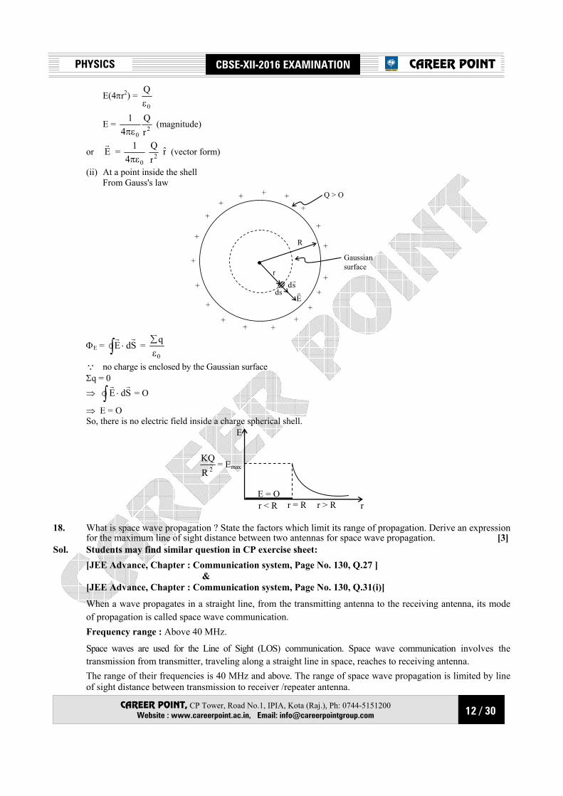
16. (i) A screen is placed at a distance of 100 cm from an object. The image of the object is formed on the screen by a convex lens for two different location of the lens separated by 20 cm. Calculate the focal length of the lens used.
(ii) A converging lens is kept coaxially in contact with a diverging lens-both the lenses being of equal focal length. What is the focal length of the combination ? [3]
Sol. Students may find similar question in CP exercise sheet: [(i) JEE Advance, Chapter : Refraction at curved surface, Page No. 24, Q.22] [(ii) JEE Advance, Chapter : Refraction at curved surface, Page No. 27, Q.1]
(i) Position
(1) Position
(2)
I
Screen
O
x (100–x) 20 cm
Lens at position (1) Object distance, u = –x Image distance, v = (100 – x) Using lens formula
f1 =
v1 –
u1
f1 =
x–1001 +
x1 …(1)
Lens at position (2) Object distance, u = – (x + 20) Image distance, v = (80 – x) Using lens formula
f1 =
v1 –
u1
f1 =
)x–80(1 +
20x1+
…(2)
Solving equation (1) & (2) f = 24 cm. (ii)
(both are of equal focal length = f ) equivalent power of combination PeqL = P1 + P2

11 / 30
PHYSICS CBSE-XII-2016 EXAMINATION
CAREER POINT, CP Tower, Road No.1, IPIA, Kota (Raj.), Ph: 0744-5151200 Website : www.careerpoint.ac.in, Email: [email protected]
CAREER POINT
PeqL =
−+
+ f1
f1
PeqL = 0
0f
1
eqL= ⇒ ∞=Leqf
focal length of the combination is infinite. 17. Find the electric field intensity due to a uniformly charged spherical shell at a point (i) outside the shell and (ii) inside the shell. Plot the graph of electric field with distance from the centre of the shell. [3] Sol. Students may find similar question in CP exercise sheet: [JEE Main, Chapter : Electrostatics, Page No. 34, Q.9 ]
Object : Here we have to find electric field intensity due to a uniformly charged spherical conducting shell at outside point.
Given : Here it is given that radius of shell is R and a positive charge Q distributed uniformly on the surface of a thin spherical shell of radius R.
Procedure : To determine electric field intensity at a point P outside the sphere such that OP = r ; (r > R)
r
++
+
+
+++
+
+
+
+
RO
dS
Sdr
Er
P
Q > 0
Gaussian surface (spherical)
We construct a sphere of radius r as a Gaussian surface as shown in figure and take a small area elements ds on it
and direction of sdr
will be radially outward Total electric flux through Gaussian Surface Now from Gauss's law
ΦE = ∫ ⋅ SdErr
= 0
qεΣ
Where Σq = net charged enclosed in Gaussian Surface Q at point P direction of electric field E
r and sd
r is same i.e. θ = 0º and Σq = Q
⇒ ∫ º0cosEds = 0
Qε
⇒ ∫ Eds = 0
Qε
As electric field (magnitude) is constant at every point on Gaussian Surface Q | E
r| = constant
E ∫ ds = 0
Qε
∫ ds = Surface area of Gaussian Surface = 4πr2
12 / 30
PHYSICS CBSE-XII-2016 EXAMINATION
CAREER POINT, CP Tower, Road No.1, IPIA, Kota (Raj.), Ph: 0744-5151200 Website : www.careerpoint.ac.in, Email: [email protected]
CAREER POINT
E(4πr2) = 0
Qε
E = 20 r
Q4
1πε
(magnitude)
or Er
= 04
1πε 2r
Q r (vector form)
(ii) At a point inside the shell From Gauss's law
r
+
++++
+
+
+
+
+
+R
Gaussian surface
+
++ +
++
+
+
Q > O
dssdr
Er
ΦE = ∫ ⋅ SdErr
= 0
qε∑
Q no charge is enclosed by the Gaussian surface Σq = 0 ⇒ ∫ ⋅ SdE
rr = O
⇒ E = O So, there is no electric field inside a charge spherical shell.
r > RE = Or < R r = R r
E
2RKQ
= Emax
18. What is space wave propagation ? State the factors which limit its range of propagation. Derive an expression
for the maximum line of sight distance between two antennas for space wave propagation. [3] Sol. Students may find similar question in CP exercise sheet: [JEE Advance, Chapter : Communication system, Page No. 130, Q.27 ] & [JEE Advance, Chapter : Communication system, Page No. 130, Q.31(i)]
When a wave propagates in a straight line, from the transmitting antenna to the receiving antenna, its mode of propagation is called space wave communication.
Frequency range : Above 40 MHz.
Space waves are used for the Line of Sight (LOS) communication. Space wave communication involves the transmission from transmitter, traveling along a straight line in space, reaches to receiving antenna.
The range of their frequencies is 40 MHz and above. The range of space wave propagation is limited by line of sight distance between transmission to receiver /repeater antenna.

13 / 30
PHYSICS CBSE-XII-2016 EXAMINATION
CAREER POINT, CP Tower, Road No.1, IPIA, Kota (Raj.), Ph: 0744-5151200 Website : www.careerpoint.ac.in, Email: [email protected]
CAREER POINT
RR
A
PhC
zline of sight
Earth
h <<< R
h = height of antenna
r = Radius of earth
Range = cA
As h is very small CA ≈ PA
using plythagores theorem
PA2 + R2 = (R + h)2
PA2 + R2 = R2 + 2Rh + h2
(neglecting h2)
PA = Rh2
Range ⇒ Rh2 on ground surface
TTransmitter
R
Receiver
hR
DC
A
hT
Total range on ground = CA + AD = RT Rh2Rh2 +
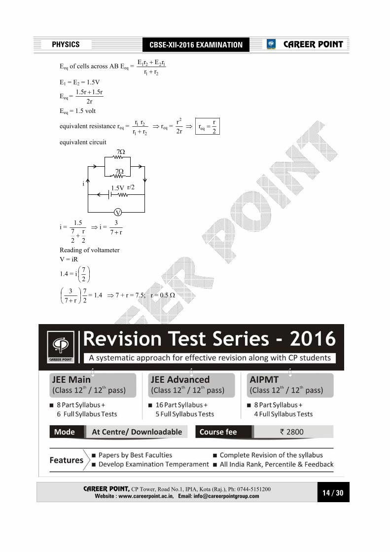
19. Two identical cells of emf 1.5 V each joined in parallel supply energy to an external circuit consisting of two resistances of 7Ω each joined in parallel. A very high resistance voltmeter reads the terminal voltage of cells to be 1.4 V. Calculate the internal resistance of each cell. [3]
Sol.
Vr
B r1.5VA
7Ω
7Ω
1.5V
14 / 30
PHYSICS CBSE-XII-2016 EXAMINATION
CAREER POINT, CP Tower, Road No.1, IPIA, Kota (Raj.), Ph: 0744-5151200 Website : www.careerpoint.ac.in, Email: [email protected]
CAREER POINT
Eeq of cells across AB Eeq = 21
1221
rrrErE
++
E1 = E2 = 1.5V
Eeq = r2
r5.1r5.1 +
Eeq = 1.5 volt
equivalent resistance req = 21
21
rrrr
+ ⇒ req =
r2r2
⇒ 2rreq =
equivalent circuit
r/2 1.5V
7Ω
7Ω
V
i
i =
2r
27
5.1
+ ⇒ i =
r73+
Reading of voltameter V = iR
1.4 = i
27
+ r73
27 = 1.4 ⇒ 7 + r = 7.5; r = 0.5 Ω

15 / 30
PHYSICS CBSE-XII-2016 EXAMINATION
CAREER POINT, CP Tower, Road No.1, IPIA, Kota (Raj.), Ph: 0744-5151200 Website : www.careerpoint.ac.in, Email: [email protected]
CAREER POINT
20. (i) Name two important processes that occur during the formation of an pn junction. (ii) Draw the circuit diagram of a full wave rectifier along with the input and output waveforms. Briefly
explain how the output voltage/current is unidirectional. [3] Sol. Students may find similar question in CP exercise sheet: [(i) JEE Advance, Chapter : Semiconductor Devices, Page No. 33, Q.64] [(ii) JEE Advance, Chapter : Semiconductor Devices, Page No. 33, Q.66] (i)
Depletionlayer
VB p n
– +
B During formation of p-n junction, diffusion and drift of charge takes place. (ii) Rectification: Rectification means conversion of ac into dc. A p-n diode acts as a rectifier because an ac
changes polarity periodically and a p-n diode conducts only when it is forward biased; it does not conduct when reverse biased.
16 / 30
PHYSICS CBSE-XII-2016 EXAMINATION
CAREER POINT, CP Tower, Road No.1, IPIA, Kota (Raj.), Ph: 0744-5151200 Website : www.careerpoint.ac.in, Email: [email protected]
CAREER POINT
I
r
B
lr
d
Working: The AC input voltage across secondary s1 and s2 change polarity after each half cycle. Suppose during the first half cycle of input AC signal, the terminal s1 is positive relative to centre tap O and s2 is negative relative to O. Then diode D1 is forward biased and diode D2 is reverse biased. Therefore, diode D1 conducts while diode D2 does not. The direction of current (i1) due to diode D1 in load resistance RL is directed from A to B. In next half cycle, the terminal s1 is negative and s2 is positive relative to centre tap O. The diode D1 is reverse biased and diode D2 is forward biased. Therefore, diode D2 conducts while D1 does not. The direction of current (i2) due to diode D2 in load resistance RL is still from A to B. Thus the current in load resistance RL is in the same direction for both half cycle of input AC voltage. Thus for input AC signal the output current is a continuous series of unidirectional pulses.
In a full wave rectifier, if input frequency is f hertz, then output frequency will be 2f hertz because for each cycle of input, two positive half cycles of output are obtained.
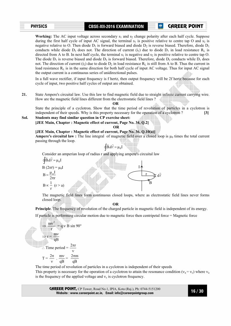
21. State Ampere's circuital law. Use this law to find magnetic field due to straight infinite current carrying wire.
How are the magnetic field lines different from the electrostatic field lines ? OR
State the principle of a cyclotron. Show that the time period of revolution of particles in a cyclotron is independent of their speeds. Why is this property necessary for the operation of a cyclotron ? [3]
Sol. Students may find similar question in CP exercise sheet: [JEE Main, Chapter : Magnetic effect of current, Page No. 34, Q.2] OR [JEE Main, Chapter : Magnetic effect of current, Page No. 36, Q.10(a)] Ampere's circuital law : The line integral of magnetic field over a closed loop is µ0 times the total current
passing through the loop. ∫ = Iµd.B 0l
rr
Consider an amperian loop of radius r and applying ampere's circuital law ∫ = Iµd.B 0l
rr
B (2πr) = µ0I
r2IB o
πµ
=
r1B ∝ (r > a)
The magnetic field lines form continuous closed loops, where as electrostatic field lines never forms closed loop.
OR Principle. The frequency of revolution of the charged particle in magnetic field is independent of its energy.
If particle is performing circular motion due to magnetic force then centripetal force = Magnetic force
⇒ r
mv2 = q ν B sin 90°
⇒ r = qBmν
∴Time period = νπr2
T = νπ2 .
qBmν =
qBm2π
The time period of revolution of particles in a cyclotron is independent of their speeds This property is necessary for the operation of a cyclotron to attain the resonance condition (νa = νc) where νa
is the frequency of the applied voltage and νc is cyclotron frequency.
17 / 30
PHYSICS CBSE-XII-2016 EXAMINATION
CAREER POINT, CP Tower, Road No.1, IPIA, Kota (Raj.), Ph: 0744-5151200 Website : www.careerpoint.ac.in, Email: [email protected]
CAREER POINT
22. How are electromagnetic waves produce ? What is the source of energy of these waves ? Write mathematical expressions for electric and magnetic fields of an electromagnetic wave propagating along the z-axis. Write any two important properties of electromagnetic waves. [3]
Sol. Students may find similar question in CP exercise sheet: [JEE Advance, Chapter : EMW, Page No. 93, Q.48]
Electromagnetic waves are produced by accelerated or oscillating charges and do not need any medium for propagation.
The source of energy of these waves are energy of oscillating charge particle.
Mathematical expressions for electric and magnetic fields of an electromagnetic wave propagating along the z-axis – Ex = E0 sin [kz – ωt]
By = B0 sin [kz – ωt]
Properties of electromagnetic waves
1. The direction of E, B and direction of propagation of waves are mutually perpendicular to one another.
2. The amplitude ratio of E and B gives velocity of light.
3. Electromagnetic waves are not deflected by electric and magnetic fields.
SECTION-D
23. Seema's uncle was advised by his doctor to have an MRI (Magnetic Resonance Imaging) scan of his brain. Her uncle felt it to be expensive and wanted to postpone it.
When Seema learnt about this, she took the help of her family and also approached the doctor, who also offered a substantial discount. She then convinced her uncle to undergo the test to enable the doctor to know the condition of his brain. The information thus obtained greatly helped the doctor to treat him properly.
Based on the above paragraph, answer the following questions: (a) What according to you are the values displayed by Seema, her family and the doctor ? (b) What could be the possible reason for MRI test to be so expensive ? (c) Assuming that MRI test was performed using a magnetic field of 0.1 T., find the minimum and
maximum values of the force that the magnetic field could exert on a proton (charge = 1.6 × 10⁻¹⁹ C) moving with a speed of 104 m/s. [4]
Sol. (a) Depend on student what he / she think about value of Seema (b) Availability of MRI test is very less. Only in big Hospital it is available so due to monopoly of big
hospital they are just charging huge amount.
(c) Force experienced by proton Fr
= q )BV(rr
×
|F|r
= q vBsinθ
maximum force max|F|r
= qvB
⇒ max|F|r
= 1.6 × 10–19 ×104×0.1
max|F|r
= 1.6 × 10⁻¹⁶ N
Minimum force min|F|r
= Zero

18 / 30
PHYSICS CBSE-XII-2016 EXAMINATION
CAREER POINT, CP Tower, Road No.1, IPIA, Kota (Raj.), Ph: 0744-5151200 Website : www.careerpoint.ac.in, Email: [email protected]
CAREER POINT
SECTION-E 24. (a) Why does unpolarised light from a source show a variation in intensity when viewed through a polaroid
which is rotated ? Show with the help of a diagram, how unpolarised light from sun gets linearly polarised by scattering.
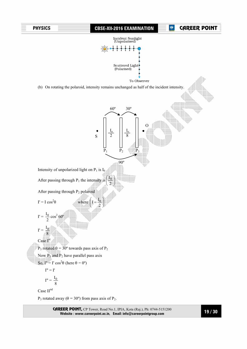
(b) Three identical polaroid sheets P1, P2 and P3 are oriented so that the pass axis of P2 and P3 are inclined at angles of 60º and 90º respectively with the pass axis of P1. A monochromatic source S of unpolarized light of intensity I0 is kept in front of the polaroid sheet P1 as shown in the figure. Determine the intensities of light as observed by the observer at O, when polaroid P3 is rotated with respect to P2 at angles θ = 30º and 60º. [5]
P1 P2 P3
S•
O•
OR
(c) Derive an expression for path difference in Young's double slit experiment and obtain the conditions for constructive and destructive interference at a point on the screen.
(b) The intensity at the central maxima in Young's double slit experiment is I0. Find out the intensity at a
point where the path difference is 4
,6
λλ and 3λ .
Sol. Students may find similar question in CP exercise sheet: [(a) JEE Advance, Chapter : Polarization, Page No. 250, Q.3] OR [(a) JEE Advance, Chapter : Wave nature of light, Page No. 20, Q.2] [(b) JEE Advance, Chapter : Wave nature of light, Page No. 19, Q.26(ii)]
(a) When vibrations of light wave are confined to only one direction then light is called linearly polarised.
unpolarised polarised
When sunlight passes through polaroid then components parallel to axis passes unaffected and components
perpendicular to axis are absorbed so transmitted light is polarised. As Fig. shows, the incident sunlight is unpolarised. The dots stand for polarisation perpendicular to the plane
of the figure. The double arrows show polarisation in the plane of the figure. (There is no phase relation between these two in unpolarised light). Under the influence of the electric field of the incident wave the electrons in the molecules acquire components of motion in both these directions. We have drawn an observer looking at 90° to the direction of the sun. Clearly, charges accelerating parallel to the double arrows do not radiate energy towards this observer since their acceleration has no transverse component. The radiation scattered by the molecule is therefore represented by dots. It is polarised perpendicular to the plane of the figure. This explains the polarisation of scattered light from the sky.
19 / 30
PHYSICS CBSE-XII-2016 EXAMINATION
CAREER POINT, CP Tower, Road No.1, IPIA, Kota (Raj.), Ph: 0744-5151200 Website : www.careerpoint.ac.in, Email: [email protected]
CAREER POINT
(b) On rotating the polaroid, intensity remains unchanged as half of the incident intensity.
S
O
60º 30º
90º
P1 P2 P3
Io 2
Io 8
Intensity of unpolarized light on P1 is I0
After passing through P1 the intensity is
2I0
After passing through P2 polaroid
I' = I cos2θ where
=
2II 0
I' = 2I0 cos2 60º
I' = 8I0
Case Ist
P3 rotated θ = 30º towards pass axis of P2
Now P3 and P2 have parallel pass axis
So, I'' = I' cos2θ (here θ = 0º)
I" = I'
I" = 8I0
Case IInd
P3 rotated away (θ = 30º) from pass axis of P2.
20 / 30
PHYSICS CBSE-XII-2016 EXAMINATION
CAREER POINT, CP Tower, Road No.1, IPIA, Kota (Raj.), Ph: 0744-5151200 Website : www.careerpoint.ac.in, Email: [email protected]
CAREER POINT
Now angle between pass axis of P2 & P3 will be
φ = 60º
I" = I' cos260º
So I" = 8I0
2
21
I" = 32I0
Case IIIrd :
P3 rotated towards pass axis of P2 by θ = 60º
Now again angle between pass axis of P2 & P3 will be
φ = 30º
So I" = I' cos230º
So I" = 8I0
2
23
⇒ I" = 32I3 0
Case IVrd
P3 rotated away from pass axis of P by θ = 60
Now angle between pass axis of P2 & P3 will be
φ = 90º
So I" = I' cos290º
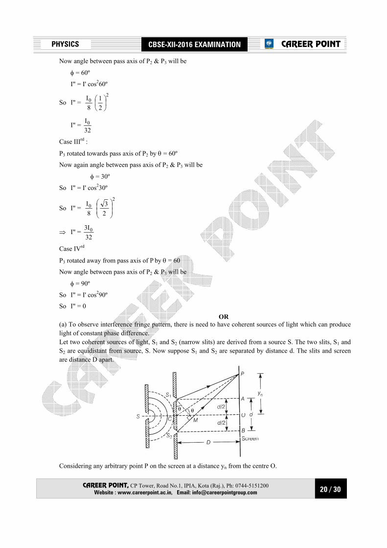
So I" = 0 OR (a) To observe interference fringe pattern, there is need to have coherent sources of light which can produce
light of constant phase difference. Let two coherent sources of light, S1 and S2 (narrow slits) are derived from a source S. The two slits, S1 and
S2 are equidistant from source, S. Now suppose S1 and S2 are separated by distance d. The slits and screen are distance D apart.
Considering any arbitrary point P on the screen at a distance yn from the centre O.
21 / 30
PHYSICS CBSE-XII-2016 EXAMINATION
CAREER POINT, CP Tower, Road No.1, IPIA, Kota (Raj.), Ph: 0744-5151200 Website : www.careerpoint.ac.in, Email: [email protected]
CAREER POINT
The path difference between interfering waves is given by S2P – S1P i.e., Path difference = S2P – S1P i.e., Path difference = S2P – S1P = S2M = d sinθ where, S1M ⊥ S2P [Q ∠S2S1 M = ∠OCP (By geometry) ⇒ S1P = PM ⇒ S2P = S2M] If θ is small, then sinθ ≈ θ ≈ tanθ ∴ Path difference, S2P – S1P = S2M = d sin θ ≈ d tanθ
Path difference = d
Dyn …(i)
[Q In ∆PCO, tan θ =COOP =
Dyn ]
For constructive interference Path difference = nλ, where, n = 0, 1, 2, …
D
dyn = nλ [From Eq. (i)]
⇒ yn = dDnλ
⇒ yn+1 = d)1n(D λ+
Q Fringe width of dark fringe = yn+1 – yn
[Q dark fringe exist between two bright fringes]
β =d
Dλ (n + 1) –d
Dnλ =d
dλ (n + 1 – n) =d
Dλ
Fringe width of dark fringe, β =d
Dλ …(ii)
For destructive interference
Path difference = (2n – 1)2λ , where n = 1, 2, 3, …
⇒ D
dy'n = (2n – 1)
2λ [From Eq. (i)]
⇒ 'ny =
d2D)1n2( λ−
where, 'ny is the separation of nth order dark fringe from central fringe.
∴ '1ny + = (2n +1)
d2Dλ
∴ Fringe width of bright fringe = Separation between (n + 1)th and nth order dark fringe from centred fringe, ⇒ β = '
1ny + – 'ny
or β =d2
D)1n2( λ+ –d2
D)1n2( λ−
22 / 30
PHYSICS CBSE-XII-2016 EXAMINATION
CAREER POINT, CP Tower, Road No.1, IPIA, Kota (Raj.), Ph: 0744-5151200 Website : www.careerpoint.ac.in, Email: [email protected]
CAREER POINT
=d2
Dλ [2n + 1 – 2n + 1] =d2
Dλ [2]
Fringe width of bright fringe.
β =d
Dλ …(iii)
From Eqs. (ii) and (iii), we can see that, fringe width of dark fringe = fringe width of bright fringe
β =d
Dλ
The fringe width decrease as wavelength gets reduced when interference set up is taken from air to water. (b) Intensity at central maxima is given = I0
⇒ Imax = I0
Intensity of resultant wave when the light waves interfere at ∆φ phase difference is
Ires = Imax cos2
φ∆
2
Ires = Io cos2
φ∆
2 (∆φ = phase difference)
(1) Path difference
∆x = 6λ
∆φ = λπ2
∆x ⇒ ∆φ =
λ
λπ
62 ⇒ ∆φ =
3π
Ires = Io cos2
π
23
Ires = Io cos2
π
6
Ires = Io
2
23
Ires = 4I3 o
(2) Path difference ∆x = 4λ
∆φ = λπ2 ∆x ⇒ ∆φ =
λπ2
λ
4 ⇒ ∆φ =
2π
Ires = Io cos2
π
22/
23 / 30
PHYSICS CBSE-XII-2016 EXAMINATION
CAREER POINT, CP Tower, Road No.1, IPIA, Kota (Raj.), Ph: 0744-5151200 Website : www.careerpoint.ac.in, Email: [email protected]
CAREER POINT
Ires = Io cos2
π
4
⇒ Ires = Io 2
21
⇒ Ires = 2I0
(3) Path difference ∆x = 3λ
∆φ = λπ2 (∆x) ⇒ ∆φ =
λπ2 ×
3λ
∆φ = 3
2π
Ires = Io cos2
π
23
2
Ires = I0 cos2
π
3
⇒ Ires = Io 2
21
⇒ Ires = 4I0
25. (a) Distinguish, with the help of a suitable diagram, the difference in the behaviour of a conductor and a
dielectric placed in an external electric field. How does polarised dielectric modify the original external field ?
(b) A capacitor of capacitance C is charged fully by connecting it to a battery of emf E. It is then disconnected from the battery. If the separation between the plates of the capacitor is now doubled, how will the following change ? [5]
(i) charge stored by the capacitor. (ii) field strength between the plates. (iii) energy stored by the capacitor. Justify your answer in each case.
OR (a) Explain why, for any charge configuration, the equipotential surface through a point is normal to the
electric field at that point. Draw a sketch of equipotential surfaces due to a single charge (–q), depicting the electric field lines due
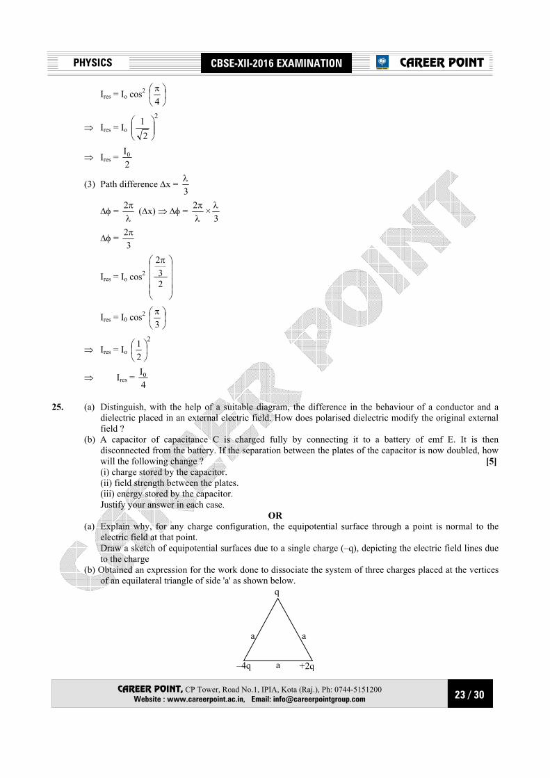
to the charge (b) Obtained an expression for the work done to dissociate the system of three charges placed at the vertices
of an equilateral triangle of side 'a' as shown below. q
aa
–4q +2qa

24 / 30
PHYSICS CBSE-XII-2016 EXAMINATION
CAREER POINT, CP Tower, Road No.1, IPIA, Kota (Raj.), Ph: 0744-5151200 Website : www.careerpoint.ac.in, Email: [email protected]
CAREER POINT
Sol. Students may find similar question in CP exercise sheet: [(b) JEE Main, Chapter : Capacitance, Page No.26, Q.24] OR [(b) JEE Main, Chapter : Electrostatic, Page No. 28, Q.41] Sol. (a) When conductor is placed in an external electric field then induction phenomena occur, due to which induced charge get develop on the conductor surface.
E=0
++++
++
––– – – – ––
E
When dielectric is placed in an external electric field then polarization phenomena will occur.
E
– + – + – +– + – + – +– + – + – +
E
– + – + – +– + – + – +
(b) After disconnected from battery and doubling the separation between two plates
(i) charge on capacitor remains same.
i.e., CV = C′ V′
⇒ CV = ′
V
2C
⇒ V′ = 2V (ii) Q Electric field between the plates
E′ = d2V2
dV
=′′
E′ = EdV
=
⇒ Electric field between the two plates remains same.
(iii) Energy stored in capacitor when connected from battery
U1 = C2
q2
Now, energy stored in capacitor after disconnection from battery
U2 = Cq
2C2
q)'C(2
q 222=
×
=
25 / 30
PHYSICS CBSE-XII-2016 EXAMINATION
CAREER POINT, CP Tower, Road No.1, IPIA, Kota (Raj.), Ph: 0744-5151200 Website : www.careerpoint.ac.in, Email: [email protected]
CAREER POINT
⇒ U2 = 2
C2q2
= 2U1
U2 = 2 U1
Energy stored in capacitor gets doubled to its initial value. OR
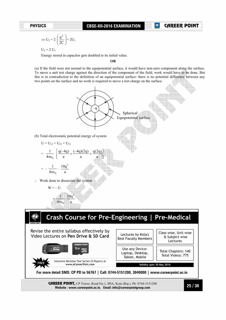
(a) If the field were not normal to the equipotential surface, it would have non-zero component along the surface. To move a unit test charge against the direction of the component of the field, work would have to be done. But this is in contradiction to the definition of an equipotential surface: there is no potential difference between any two points on the surface and no work is required to move a test charge on the surface.
–q Spherical Equipotential surface
(b) Total electrostatic potential energy of system
U = U12 + U23 + U31
= 04
1πε
++
a)q2(q
a)q2)(q4(–
a)q4(–q
= – 04
1πε
⋅ aq10 2
∴ Work done to dissociate the system
W = – U
= 04
1πε
aq10 2
26 / 30
PHYSICS CBSE-XII-2016 EXAMINATION
CAREER POINT, CP Tower, Road No.1, IPIA, Kota (Raj.), Ph: 0744-5151200 Website : www.careerpoint.ac.in, Email: [email protected]
CAREER POINT
26. (a) When a bar magnet is pushed towards (or away) from the coil connected to a galvanometer, the pointer in the galvanometer deflects. Identify the phenomenon causing this deflection and write the factors on which the amount and direction of the deflection depends. State the laws describing this phenomenon.
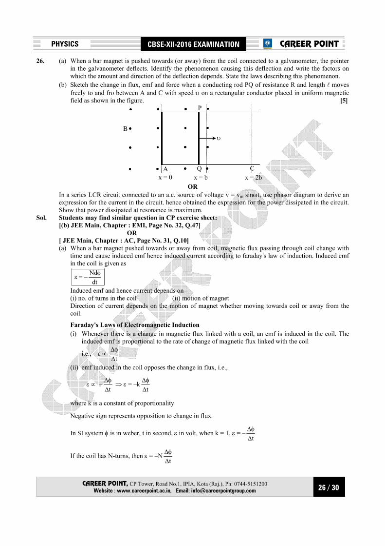
(b) Sketch the change in flux, emf and force when a conducting rod PQ of resistance R and length l moves freely to and fro between A and C with speed υ on a rectangular conductor placed in uniform magnetic field as shown in the figure. [5]
P
B υ
CQAx = 0 x = b x = 2b
OR In a series LCR circuit connected to an a.c. source of voltage v = vm sinωt, use phasor diagram to derive an
expression for the current in the circuit. hence obtained the expression for the power dissipated in the circuit. Show that power dissipated at resonance is maximum.
Sol. Students may find similar question in CP exercise sheet: [(b) JEE Main, Chapter : EMI, Page No. 32, Q.47] OR [ JEE Main, Chapter : AC, Page No. 31, Q.10] (a) When a bar magnet pushed towards or away from coil, magnetic flux passing through coil change with
time and cause induced emf hence induced current according to faraday's law of induction. Induced emf in the coil is given as
dt
Nd– φ=ε
Induced emf and hence current depends on (i) no. of turns in the coil (ii) motion of magnet Direction of current depends on the motion of magnet whether moving towards coil or away from the
coil.
Faraday's Laws of Electromagnetic Induction (i) Whenever there is a change in magnetic flux linked with a coil, an emf is induced in the coil. The
induced emf is proportional to the rate of change of magnetic flux linked with the coil
i.e., ε ∝ t∆φ∆
(ii) emf induced in the coil opposes the change in flux, i.e.,
ε ∝ –t∆φ∆ ⇒ ε = –k
t∆φ∆
where k is a constant of proportionality
Negative sign represents opposition to change in flux.
In SI system φ is in weber, t in second, ε in volt, when k = 1, ε = –t∆φ∆
If the coil has N-turns, then ε = –Nt∆φ∆

27 / 30
PHYSICS CBSE-XII-2016 EXAMINATION
CAREER POINT, CP Tower, Road No.1, IPIA, Kota (Raj.), Ph: 0744-5151200 Website : www.careerpoint.ac.in, Email: [email protected]
CAREER POINT
(b) Case I When PQ moves forward.
(i) For 0 ≤ x < b
Magnetic field, B exists in the region.
∴ Area of loop PQRS = lx
∴ Magnetic flux linked with loop PQRS,
φ = BA = Blx
φ = Blx …(i) [b > × ≥ 0]
(ii) For, 2b ≥ x ≥ b B = 0
∴ Flux linked with loop PQRS is uniform and given by
φ′ = Blb (x = b) Forward journey
Thus, for b > x ≥ 0
flux φ = Blx
⇒ φ ∝ x
For 2b ≥ x ≥ b
Flux, φ = Bbl [Constant] Return journey
For b ≤ × ≤ 2b,
φ = constant = Bbl
For 0 ≤ × ≤ b,
φ = Blx [Decreasing] Graphical representation
Forwardjourney
Returnjourney
b 2b b 0x
φ
φ = Bbl
0
Case II For b > x ≥ 0
As, φ = Blx
⇒ dtdφ = Bl
dtdx = Bvl
=
dtdxvQ
Induced emf e = – dtdφ = – vBl
For 2b ≥ x ≥ b,
As, φ′ = Bbl

28 / 30
PHYSICS CBSE-XII-2016 EXAMINATION
CAREER POINT, CP Tower, Road No.1, IPIA, Kota (Raj.), Ph: 0744-5151200 Website : www.careerpoint.ac.in, Email: [email protected]
CAREER POINT
dtd ′φ = 0
⇒ e = 0
Forward journey
For b > x ≥ 0
e = – vBl
For 2b ≥ x ≥ b
e = 0
Backward journey
For b > x ≥ 0
e = vBl
For 2b ≥ x ≥ b,
e = 0
Variation of induced emf.
Forwardjourney
Returnjourney
emfb 2b b 0
x
+ Bvl
– Bvl
OR
(a)
A series LCR circuit connected to an ac source Figure shows a series LCR circuit connected to an ac source ε. As usual, we take the voltage of the source to
be v = vm sin ωt.
VL
I VC
IIVR
π/2 π/2
CL R
~ V = V0 sinωt
VR = RI VL = XLI VC =XCI
29 / 30
PHYSICS CBSE-XII-2016 EXAMINATION
CAREER POINT, CP Tower, Road No.1, IPIA, Kota (Raj.), Ph: 0744-5151200 Website : www.careerpoint.ac.in, Email: [email protected]
CAREER POINT
VR
ε
VC
VL
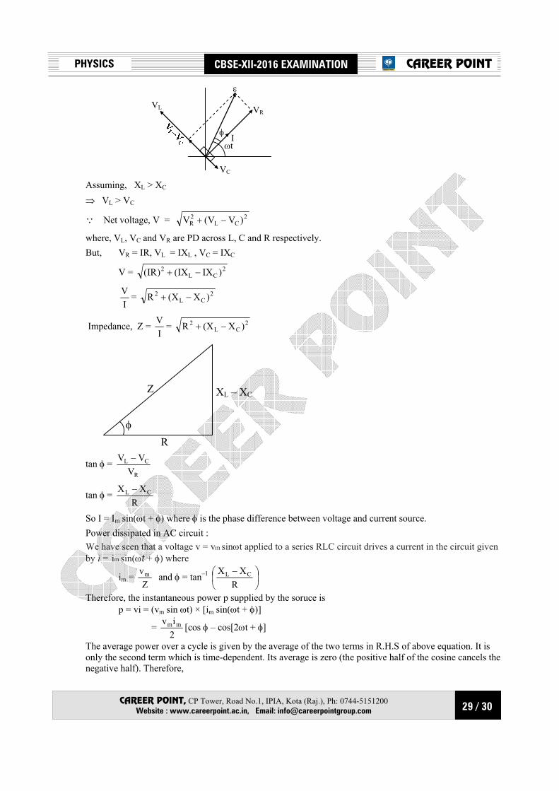
φ Iωt
Assuming, XL > XC
⇒ VL > VC
Q Net voltage, V = 2CL
2R )VV(V −+
where, VL, VC and VR are PD across L, C and R respectively. But, VR = IR, VL = IXL , VC = IXC
V = 2CL
2 )IXIX()IR( −+
IV = 2
CL2 )XX(R −+
Impedance, Z = IV = 2
CL2 )XX(R −+
Z
φ
XL – XC
R
tan φ = R
CL
VVV −
tan φ = R
XX CL −
So I = Im sin(ωt + φ) where φ is the phase difference between voltage and current source. Power dissipated in AC circuit : We have seen that a voltage v = vm sinωt applied to a series RLC circuit drives a current in the circuit given by i = im sin(ωt + φ) where
im = Z
vm and φ = tan–1
−
RXX CL
Therefore, the instantaneous power p supplied by the soruce is p = vi = (vm sin ωt) × [im sin(ωt + φ)]
= 2iv mm [cos φ – cos[2ωt + φ]
The average power over a cycle is given by the average of the two terms in R.H.S of above equation. It is only the second term which is time-dependent. Its average is zero (the positive half of the cosine cancels the negative half). Therefore,

30 / 30
PHYSICS CBSE-XII-2016 EXAMINATION
CAREER POINT, CP Tower, Road No.1, IPIA, Kota (Raj.), Ph: 0744-5151200 Website : www.careerpoint.ac.in, Email: [email protected]
CAREER POINT
P = 2iv mm cosφ =
2i
2v mm cosφ
= VI cosφ This can also be written as P = I2 Z cos φ Power dissipated at resonance in LCR circuit : At resonance XL – XC = 0. Therefore, cosφ = 1 and P = I2Z = I2. That is, maximum power is dissipated in a circuit (through R) at resonance.