Cbrc
16
CHANNEL RF BASED REMOTE CONTROL M.ABHISHEK T.JAGADISH S.PRAVEEN
Transcript of Cbrc

CHANNEL RF
BASED REMOTE
CONTROL
M.ABHISHEK
T.JAGADISH
S.PRAVEEN
INTRODUCTIONWHY IR…? WHY NOT RF…?
• Radio frequency controlled devices. RF based remote controls do not
have to be pointed and also have a better range, going through doors and
walls. Even better, radio technology is as reliable and almost as
inexpensive as infrared.
• Yes, the radio-based remote control is past due, and the infra-red based
remote control is on its way out, even to the point that within a few
years we will look back with amazement at such antique IR powered
remote controls and marvel at the fact that we had to point and shoot to
control our home entertainment systems.
• These RF remote controls will easily transmit through walls and cabinet
doors, and enable “two-way” communications.
• Channel radio frequency based remote control is the circuit in which this
circuit utilizes the RF module (TX/RX) for making a wireless remote,
which could be used to drive an output from a distant place. RF module,
as the name suggests, uses radio frequency to send signals.
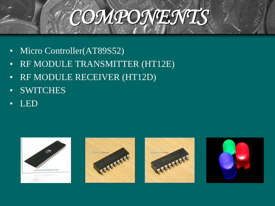
COMPONENTS
• Micro Controller(AT89S52)
• RF MODULE TRANSMITTER (HT12E)
• RF MODULE RECEIVER (HT12D)
• SWITCHES
• LED
Why Microcontroller?
• Microcontroller contains microprocessor, memory (RAM
& ROM), I/O interfacing circuit and peripheral devices
such as A/D converters, serial I/O, timers etc.
• It has many bit handling instructions.
• Less access times for built-in memory and I/O devices.
• Microcontroller based systems requires less hardware
reducing PCB size and increasing reliability.

PIN DIAGRAM OF
MICROCONTROLLER
POWER SUPPLY UNIT• Initially power supplies are designed to convert high voltage AC mains
electricity to a suitable low voltage supply for electronics circuits and other
devices. A power supply can by broken down into a series of blocks, each of
which performs a particular function. A d.c power supply which maintains the
output voltage constant irrespective of a.c mains fluctuations or load variations
is known as “Regulated D.C Power Supply”.
• Transformers convert AC electricity from one voltage to another with little loss
of power. Step-up transformers increase in output voltage, step-down
transformers decrease in output voltage. Most power supplies use a step-down
transformer to reduce the dangerously high mains voltage to a safer low voltage.
There is no electrical connection between the two coils; instead they are linked
by an alternating magnetic field created in the soft-iron core of the transformer.
Transformers waste very little power so the power out is (almost) equal to the
power in. A step-down transformer has a large number of turns on its primary
(input) coil which is connected to the high voltage mains supply, and a small
number of turns on its secondary (output) coil to give a low output voltage.

POWER SUPPLY UNIT
• A circuit which is used to convert a.c to dc is known as RECTIFIER. A bridge rectifier makes use of four diodes in a bridge arrangement to achieve full-wave rectification. This is a widely used configuration, both with individual diodes wired and with single component bridges where the diode bridge is wired internally.
• A Filter is a device which removes the a.c component of rectifier output but allows the d.c component to reach the load.
• Voltage regulator ICs is available with fixed (typically 5, 12 and 15V) or variable output voltages. Negative voltage regulators are available, mainly for use in dual supplies. Most regulators include some automatic protection from excessive current ('overload protection') and overheating ('thermal protection'). Many of the fixed voltage regulator ICs has 3 leads and look like power transistors, such as the 7805 +5V 1A regulator shown on the right. The positive lead of unregulated DC power supply (anything from 9VDC to 24VDC) is connected to the input pin, connect the negative lead to the Common pin and then the power is turned, gets a 5 volt supply from the output pin.

WORKING
• The RF module, as the name suggests, operates at Radio Frequency. The
corresponding frequency range varies between 30 kHz & 300 GHz. This RF
module comprises of an RF Transmitter and an RF Receiver.
• The transmitter/receiver (Tx/Rx) pair operates at a frequency of 434 MHz.
The RF module has been used in conjunction with a set of four channel
encoder/decoder ICs.
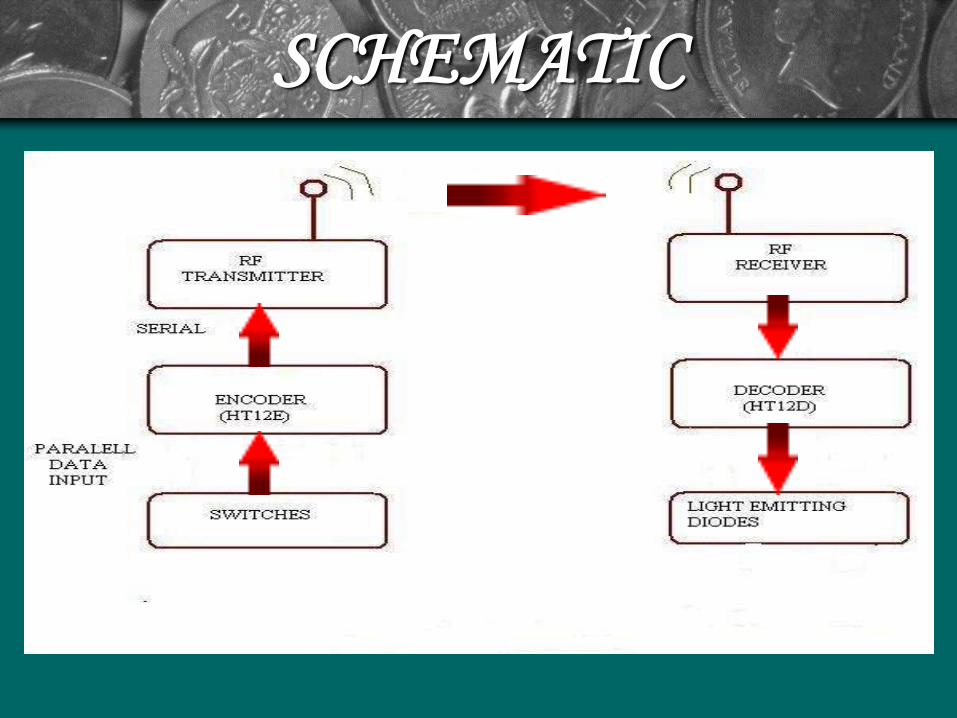
• The encoder(HT12E) converts the parallel inputs (from the remote switches) into
serial set of signals. These signals are serially transferred through RF to the
reception point. The decoder is used after the RF receiver to decode the serial
format and retrieve the original signals as outputs. These outputs can be observed
on corresponding LEDs.
SCHEMATIC

ADVANTAGES
• Not line of sight means it can penetrate through most solids and
pass through walls.
• Longer range.
• RF allows two-way communication.
• Not as sensitive to weather/environmental conditions.

DISADVANTAGES
• Interference: communication devices using similar frequencies -
wireless phones.
• Lack of security: easier to "eavesdrop" on transmissions since
signals are spread out in space rather than confined to a wire
• Higher cost than infrared

APPLICATIONS
• Commonly used in remote control of TVs, VCRs and CD players
• Home automation.
• Commands can be sent directly to the robot.
CONCLUSION
The adoption of RF remote controls is going to
change how we interact with the world around us
as well as how we take care of our environment.
Bye-bye IR. Hello, RF.
BIBLIOGRAPHY• 8051 Microcontroller: An Applications Based Introduction
by David Calcutt, Frederick Cowan, and Hassan Parchizadeh
• 8051 Microcontrollers, Hardware, Software, and Applicationsby D. M. Calcutt
• C and the 8051by Tom Schultz
• www.atmel.com
• www.circuitxpert.com/blog/2009/04/4-channel-rf-remote-control
• http://www.coolcircuit.com/project/rf_remote/
• www.electronicsmaker.com/em/admin/pdf/free/4%20channel%20RF%20remote.pdf
• www.wikipedia.com

THANK YOU

QUERIES ???