CAVITATION TUBE SPARGING SYSTEMS - … · 3 CAVITATION TUBE SPARGING The Cav-Tube design is based...
8
CAVITATION TUBE SPARGING SYSTEMS FGB-103
Transcript of CAVITATION TUBE SPARGING SYSTEMS - … · 3 CAVITATION TUBE SPARGING The Cav-Tube design is based...

CAVITATION TUBE SPARGING SYSTEMS
Website: flotation.eriez.com
FGB-103

CAV-TUBE SPARGERSGenerate picobubbles to substantially improve flotation kinetics and increase the recovery of ultrafines.
Cavitation Tube spargers are the heart of the patented bubble generation technique used in EFD column flotation cells. The specially designed “Cav-Tubes” are an integral part of the hydrodynamic aeration system used to maximize fine bubble generation and improve bubble-particle collision rates.
Cav-Tubes can also be used as part of a pre-aeration system that can be applied independently in a flotation feed line or part of a separate equipment package to increase the recovery of overloaded circuits or improve the flotation response of “hard-to-float” material.
Applications include: • Aeration of Column Flotation Cells • Pre-Aeration Systems
An acrylic model of an Eriez CPT Cavitation Tube showing the generation of picobubbles.
Typical installation of the Cav-Tube hydrodynamic spargers for recovery of fine potash.
2
3
CAVITATION TUBE SPARGING
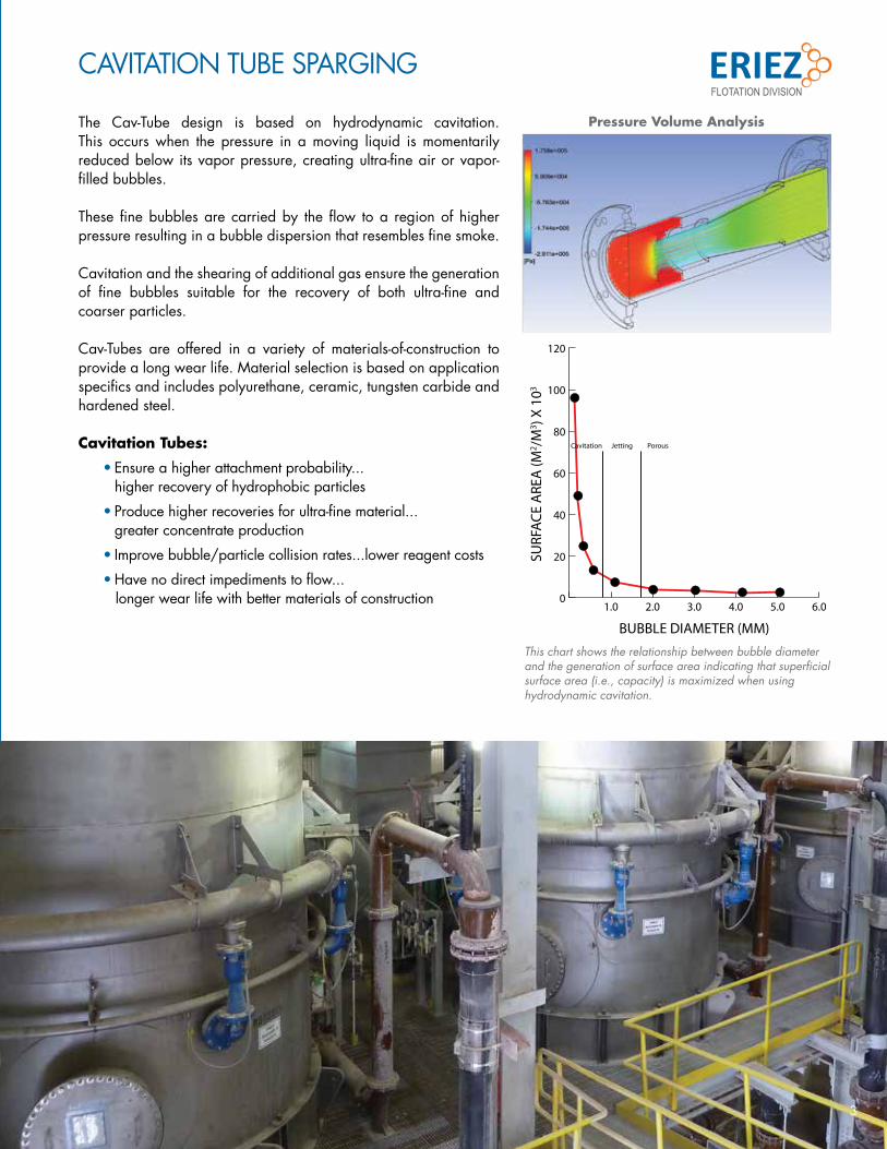
The Cav-Tube design is based on hydrodynamic cavitation. This occurs when the pressure in a moving liquid is momentarily reduced below its vapor pressure, creating ultra-fine air or vapor-filled bubbles.
These fine bubbles are carried by the flow to a region of higher pressure resulting in a bubble dispersion that resembles fine smoke.
Cavitation and the shearing of additional gas ensure the generation of fine bubbles suitable for the recovery of both ultra-fine and coarser particles.
Cav-Tubes are offered in a variety of materials-of-construction to provide a long wear life. Material selection is based on application specifics and includes polyurethane, ceramic, tungsten carbide and hardened steel.
Cavitation Tubes:
• Ensure a higher attachment probability... higher recovery of hydrophobic particles
• Produce higher recoveries for ultra-fine material... greater concentrate production
• Improve bubble/particle collision rates...lower reagent costs
• Have no direct impediments to flow... longer wear life with better materials of construction
This chart shows the relationship between bubble diameter and the generation of surface area indicating that superficial surface area (i.e., capacity) is maximized when using hydrodynamic cavitation.
1.0 2.0 3.0 4.0 5.0 6.00
20
40
60
80
100
120
BUBBLE DIAMETER (MM)
SURF
ACE
ARE
A (M
2 /M3 ) X
103
Cavitation Jetting Porous
Pressure Volume Analysis

For more information, visit flotation.eriez.com4
PICOBUBBLE ENHANCED FLOTATIONUltra fine bubbles naturally exist in liquids and can be created through dynamic cavitation. These picobubbles readily attach to hydrophobic particles due to their lower ascending and rebound velocities and the improved free-energy conditions.
Combining cavitation-induced bubble generation with mechanically generated bubbles produces higher flotation recoveries than by either method alone. This synergistic effect is caused by the nucleation of picobubbles on the particle surface.
Picobubbles improve the flotation response by acting as a secondary “collector,” enhancing the bubble-particle attachment probability and reducing detachment.
Cavitation-Tube sparging systems have been demonstrated on an industrial scale in base metals, sulfides and non-metallic applications. These installations have yielded improvements in recovery, reagent consumption and wear.
PicobubblesParticle
Bubble
Bubble
40 45 50 55 60 65 70 75 80 85 90 95 10020
25
30
35
40
45
50
55
60
SULFIDE RECOVERY (%)
GRA
DE
(%)
Traditional Air Lance
Eriez - Cavitation
Improved Recoveries
Fine, stable froth generated using Cavitation-Tube Sparging System.
Improvement in sulfide recovery using the Cavitation-Tube sparging system when treating -50 micron fines.

5For more information, visit flotation.eriez.com
Eriez’ Cavitation Tube systems consist of a centrifugal recycle pump, a slurry distribution manifold and a series of spargers designed to induce cavitation and generate fine bubbles. In operation, a portion of underflow slurry is drawn from the column and pumped to a distribution manifold where it is divided equally between the Cavitation Tube spargers. Process air is injected under pressure at the inlet of the cavitation tube to provide additional air for flotation. The two-phase mixture passes though the Cav-Tube sparger and is reinjected into the bottom of the column cell with the air dispersed as fine bubbles.
FEED INLET
AIR MANIFOLD
UNDERFLOWDISCHARGE VALVE
FROTH PRODUCT
SLURRY RECIRCULATION PUMP
FROTH LAUNDER
ADJUSTABLE WASH WATER DISTRIBUTOR
SLURRY MANIFOLD
CAV-TUBE
TYPICAL ARRANGEMENT: CAVITATION TUBE SPARGING
EFD Column cell with Cav-Tubes installed for ultra-fine niobium recovery (20x5 micron).

6
PRE-AERATION SYSTEM
RETROFIT INSTALLATIONS
Flotation circuit performance can be improved by integrating the Cav-Tube technology with the EFD feed pre-aeration system, the Feed Air Jet.
This performance improvement is a result of aerating slurry where the concentration of floatable material is highest - the feed.
This approach can be applied independently to circuit feed lines to improve the kinetics and capacity of overloaded flotation cells in addition to improving the recovery of “hard-to-float” material.
Cav-Tube spargers, unlike static mixers, do not use “wear-prone” internal components. The slurry is forced through an orifice instead of around internal mixing vanes. As a result, customers have been able to retrofit Cav-Tubes into existing column circuits providing both improved metallurgy and maintenance. Cav-Tubes can also be used to replace older style air-lance systems to gain additional recovery in ultra-fine applications.
Phosphate industry user stated, “…we replaced inline static mixers with Eriez’ Cav-Tubes and the recoveries are better, wear is negligible…”
Feed Air Jet Pre-Aeration System
7
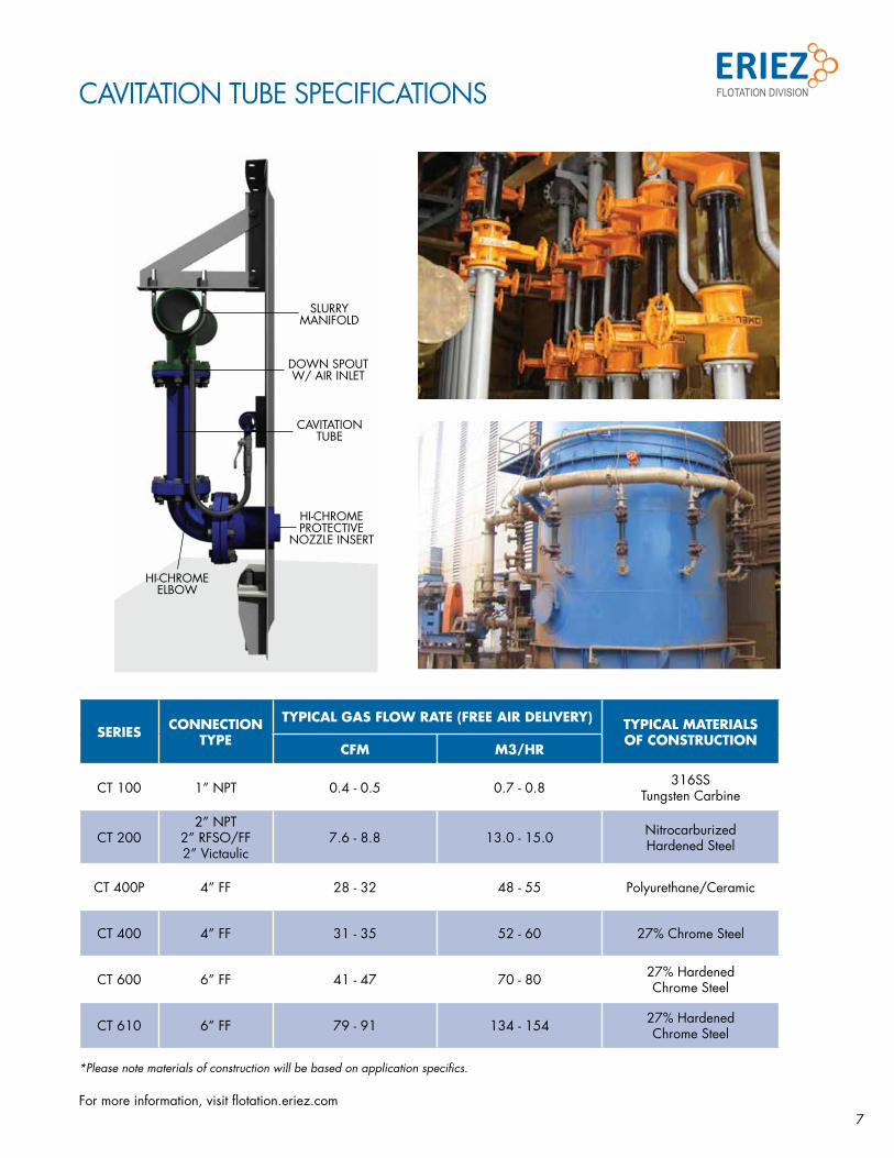
CAVITATION TUBE SPECIFICATIONS
SLURRY MANIFOLD
DOWN SPOUT W/ AIR INLET
CAVITATION TUBE
HI-CHROME ELBOW
HI-CHROME PROTECTIVE
NOZZLE INSERT
SERIES CONNECTION TYPE
TYPICAL GAS FLOW RATE (FREE AIR DELIVERY) TYPICAL MATERIALS OF CONSTRUCTION
CFM M3/HR
CT 100 1” NPT 0.4 - 0.5 0.7 - 0.8 316SS Tungsten Carbine
CT 2002” NPT
2” RFSO/FF 2” Victaulic
7.6 - 8.8 13.0 - 15.0 NitrocarburizedHardened Steel
CT 400P 4” FF 28 - 32 48 - 55 Polyurethane/Ceramic
CT 400 4” FF 31 - 35 52 - 60 27% Chrome Steel
CT 600 6” FF 41 - 47 70 - 80 27% Hardened Chrome Steel
CT 610 6” FF 79 - 91 134 - 154 27% Hardened Chrome Steel
For more information, visit flotation.eriez.com
*Please note materials of construction will be based on application specifics.

414-150-AHA
Eriez Flotation Division | Canada7168 Venture StDelta, BC, V4G 1H6CanadaOffice: +1 [email protected]
Eriez Flotation Division | BrazilAv. Getúlio Vargas, n0 456 - 120 andarFuncionários – Belo Horizonte - MG Brazil Office: +55 31 3281 [email protected]
Eriez Flotation Division | ChileBadajoz, 130 Of. 1306Las Condes, SantiagoChileOffice: +56 2 [email protected]
Website: flotation.eriez.com
Lab & Pilot Equipment, Testing and Technical Service
Flotation
Hydraulic Separation
Formerly known as Canadian Process Technologies, Inc., EFD is a wholly owned subsidiary of Eriez Manufacturing Co. Eriez provides advanced testing and engineering services in addition to sparging and column flotation equipment for the mining and minerals processing industries. Eriez, HydroFloat, SlamJet and StackCell are registered trademarks of Eriez Manufacturing Co.
WORLD AUTHORITY IN ADVANCED SEPARATION TECHNOLOGIESCustomer-Focused Service Spanning the World of Minerals
Eriez Flotation Division is committed to providing state-of-the-art equipment and process solutions for new and existing projects worldwide. We understand and quickly respond with integrity, competence and effectiveness to the needs of our clients. Our versatility is demonstrated by the diversity of our engineering services and the varying sizes of projects we have successfully completed around the world.
Contact the nearest Eriez Flotation Division office for technical support or design engineering to suit your specific application.
Eriez Flotation Division | USA2200 Asbury RoadErie, PA 16506USAOffice: (814) [email protected]
Eriez Flotation Division | Australia154 Northbourne Road, Campbellfield, Victoria 3061AustraliaOffice: +61 3 9305 [email protected]
Eriez Flotation Division | PerúAv. Manuel Olguin 335, oficina 1008Surco, LimaPerúOffice: +51 1 719 [email protected]


![Effect of biogas sparging on the performance of bio ... · Effect of biogas sparging on the performance ... Kim et al. [10] studied the effect of gas sparging on ... Biogas sparging](https://static.fdocuments.net/doc/165x107/5aea00c07f8b9aee079197de/effect-of-biogas-sparging-on-the-performance-of-bio-of-biogas-sparging-on-the.jpg)