Causes and Measures for Addressing Ghost Peaks in · PDF fileTechnical Report vol.45 Causes...
4
Technical Report vol.45 Causes and Measures for Addressing Ghost Peaks in Reversed Phase HPLC Analysis One of the brain-racking challenges in LC analysis is the presence of ghost peaks (see Fig. 1). Ghost peaks are of unknown origin in a chromatogram, are easily misidentified when they are close to peaks of interest, and can result in quantitative errors when they overlap peaks of interest. Uncertainty in data quality and reliability is of course the result. To make matters worse, considerable time can easily be expended in determining the source of an apparent impurity, even if there is none associated with the compound of interest. With the increase in UV detector sensitivity that has come about in recent years, detection has become possible at very low concentrations, bringing the problem of ghost peaks into the spotlight. In this report, we focus on the source of ghost peaks in reversed phase analysis using a UV detector, and propose various remedial measures that can be effective. The sources of ghost peaks are typically divided into three categories: those due to impurities other than the target substance, internal contamination of the LC instrument, and impurities in the mobile phase, as shown below. (1) Impurities in instrument (2) Impurities in sample (3) Impurities in mobile phase 1. The Problem of Ghost Peaks 2. Ghost Peaks in Reversed Phase Analysis C190-E148 Fig. 1 Example of Ghost Peaks (data provided by Daiichi Sankyo Co., Ltd.) Fig. 2 Sources of Ghost Peaks 0 10 mAU Detection: 210 nm 0.0 10 20 min ( 2 ) Autosampler Solvent delivery pump Mobile Phase Column Column oven Detector ( 1 ) ( 3 )
-
Upload
truongliem -
Category
Documents
-
view
217 -
download
2
Transcript of Causes and Measures for Addressing Ghost Peaks in · PDF fileTechnical Report vol.45 Causes...

Technical Report vol .45
Causes and Measures for Addressing Ghost Peaks in Reversed Phase HPLC Analysis
One of the brain-racking challenges in LC analysis is the presence of ghost peaks (see Fig. 1). Ghost peaks are of unknown origin in a chromatogram, are easily misidentified when they are close to peaks of interest, and can result in quantitative errors when they overlap peaks of interest. Uncertainty in data quality and reliability is of course the result. To make matters worse, considerable time can easily be expended in determining the source of an apparent impurity, even if there is none associated with the compound of interest.With the increase in UV detector sensitivity that has come about in recent years, detection has become possible at very low concentrations, bringing the problem of ghost peaks into the spotlight. In this report, we focus on the source of ghost peaks in reversed phase analysis using a UV detector, and propose various remedial measures that can be effective.
The sources of ghost peaks are typically divided into three categories: those due to impurities other than the target substance, internal contamination of the LC instrument, and impurities in the mobile phase, as shown below.(1) Impurities in instrument(2) Impurities in sample(3) Impurities in mobile phase
1. The Problem of Ghost Peaks
2. Ghost Peaks in Reversed Phase Analysis
C190-E148
Fig. 1 Example of Ghost Peaks (data provided by Daiichi Sankyo Co., Ltd.)
Fig. 2 Sources of Ghost Peaks
0
10
mAU
Detection: 210 nm
0.0 10 20 min
( 2 )
Autosampler
Solvent delivery pump
Mobile Phase
Column
Column oven Detector
( 1 )
( 3 )
2-1. Ghost Peaks Due to Instrument
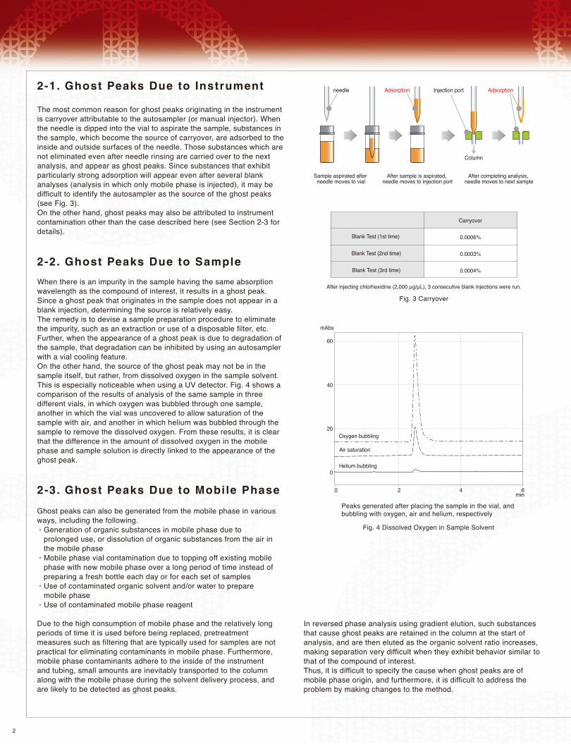
The most common reason for ghost peaks originating in the instrument is carryover attributable to the autosampler (or manual injector). When the needle is dipped into the vial to aspirate the sample, substances in the sample, which become the source of carryover, are adsorbed to the inside and outside surfaces of the needle. Those substances which are not eliminated even after needle rinsing are carried over to the next analysis, and appear as ghost peaks. Since substances that exhibit particularly strong adsorption will appear even after several blank analyses (analysis in which only mobile phase is injected), it may be difficult to identify the autosampler as the source of the ghost peaks (see Fig. 3).On the other hand, ghost peaks may also be attributed to instrument contamination other than the case described here (see Section 2-3 for details).
2
2-2. Ghost Peaks Due to Sample
When there is an impurity in the sample having the same absorption wavelength as the compound of interest, it results in a ghost peak. Since a ghost peak that originates in the sample does not appear in a blank injection, determining the source is relatively easy.The remedy is to devise a sample preparation procedure to eliminate the impurity, such as an extraction or use of a disposable filter, etc. Further, when the appearance of a ghost peak is due to degradation of the sample, that degradation can be inhibited by using an autosampler with a vial cooling feature. On the other hand, the source of the ghost peak may not be in the sample itself, but rather, from dissolved oxygen in the sample solvent. This is especially noticeable when using a UV detector. Fig. 4 shows a comparison of the results of analysis of the same sample in three different vials, in which oxygen was bubbled through one sample, another in which the vial was uncovered to allow saturation of the sample with air, and another in which helium was bubbled through the sample to remove the dissolved oxygen. From these results, it is clear that the difference in the amount of dissolved oxygen in the mobile phase and sample solution is directly linked to the appearance of the ghost peak.
2-3. Ghost Peaks Due to Mobile Phase
Ghost peaks can also be generated from the mobile phase in various ways, including the following. Generation of organic substances in mobile phase due to prolonged use, or dissolution of organic substances from the air in the mobile phase Mobile phase vial contamination due to topping off existing mobile phase with new mobile phase over a long period of time instead of preparing a fresh bottle each day or for each set of samples Use of contaminated organic solvent and/or water to prepare mobile phase Use of contaminated mobile phase reagent
Due to the high consumption of mobile phase and the relatively long periods of time it is used before being replaced, pretreatment measures such as filtering that are typically used for samples are not practical for eliminating contaminants in mobile phase. Furthermore, mobile phase contaminants adhere to the inside of the instrument and tubing, small amounts are inevitably transported to the column along with the mobile phase during the solvent delivery process, and are likely to be detected as ghost peaks.
In reversed phase analysis using gradient elution, such substances that cause ghost peaks are retained in the column at the start of analysis, and are then eluted as the organic solvent ratio increases, making separation very difficult when they exhibit behavior similar to that of the compound of interest.Thus, it is difficult to specify the cause when ghost peaks are of mobile phase origin, and furthermore, it is difficult to address the problem by making changes to the method.
needle Adsorption Injection port
Column
Adsorption
Sample aspirated after needle moves to vial
After sample is aspirated, needle moves to injection port
After completing analysis, needle moves to next sample
Fig. 3 Carryover
After injecting chlorhexidine (2,000 µg/µL), 3 consecutive blank injections were run.
Blank Test (2nd time)
Blank Test (3rd time)
Blank Test (1st time)
Carryover
0.0006%
0.0003%
0.0004%
Fig. 4 Dissolved Oxygen in Sample Solvent
Peaks generated after placing the sample in the vial, and bubbling with oxygen, air and helium, respectively
Oxygen bubbling
Air saturation
Helium bubbling
mAbs
60
40
20
0
0 2 4 6min

3
3. Uti l izing the Ghost Trap DS
Fig. 6 Ghost Trap DS Test Connection PositionsFig. 5 Ghost Trap DS Modules
Solvent delivery pump
Column ovenDetector
Gradient mixer
Column
Autosampler
Mobile phase
( b )
( d )
( e )
A
B
( c )
When identifying the cause of ghost peaks in the mobile phase as described in Section 2-3 is difficult, and drastic prevention measures are problematic, trapping of the causative substances is an effective means of suppressing the appearance of the ghost peaks.Fig. 5 and Table 1 show and describe the Ghost Trap DS cartridges that can be used to reduce or eliminate ghost peaks that are due to the mobile phase. Installing the Ghost Trap DS in the mobile phase flow line provides for adsorption of the substances responsible for the ghost peaks, especially when conducting gradient elution with reversed phase analysis and a UV detector. Ghost peaks are prevented from appearing because the mobile phase is sent to the column after removal of the problematic substances.The Ghost Trap DS can be connected at various positions in the flow line (see Fig. 6) according to the LC system configuration and the analysis application. Fig. 7 shows a comparison of the chromatographic results using the connection positions indicated in (a) to (e).
(a) Ghost Trap DS not used(b) Positioned after solvent delivery pump A (aqueous solution pump)(c) Positioned after solvent delivery pump B (organic solvent pump)(d) Positioned before gradient mixer(e) Positioned after gradient mixer
The results clearly indicate that under these conditions, many ghost peaks originate in the pump A flow line (most likely from the mobile phase rather than some contamination in pump A). It is also clear that there are slight differences in the ghost peak pattern when the Ghost Trap DS is connected before or after the gradient mixer, indicating that the presence of ghost peaks can also be due to contamination of the mixer. Since the Ghost Trap DS can also be connected downstream of the gradient mixer, more certain removal of ghost peaks can be expected, as shown in Fig. 7 (e).
(Note) When this product is connected after the gradient mixer or after the pump confluence, the system delay volume calculation must include both the mixer volume and the Ghost Trap cartridge volume when conducting gradient analysis. When a mass spectrometer is used as the detector, bleed noise may be generated due to this product. In analysis using ion pair reagents, the ion pair reagents may be retained in this product, thereby influencing retention times and peak shapes. When using this product, prior to connecting the analytical column, be sure to thoroughly rinse the trap beforehand with mobile phase (at close to the final organic concentration when conducting gradient analysis). Please be aware that all impurities cannot be removed with the Ghost Trap DS, but a significant reduction in the presence of ghost peaks can be expected, as shown in Fig. 7.
Table 1 Ghost Trap DS Modules
Description (Quantity) Size Internal Volume Pressure Tolerance
Ghost Trap DS
Cartridges (2)
700 µL (Approx.)
35 MPa
Cartridges (2)
150 µL (Approx.)20 mmL. × 4.0 mmI.D.
30 mmL. × 7.6 mmI.D.
Cartridges (2)
Holder (1)
Cartridges (2)
Holder (1)
P/NPart Name
228-59921-91
228-59921-92
228-59921-93
228-59921-94

SHIMADZU CORPORATION. International Marketing Division3. Kanda-Nishikicho 1-chome, Chiyoda-ku, Tokyo 101-8448, Japan Phone: 81(3)3219-5641 Fax. 81(3)3219-5710URL http://www.shimadzu.com
Founded in 1875, Shimadzu Corporation, a leader in the development of advanced technologies, has a distinguished history of innovation built on the foundation of contributing to society through science and technology. We maintain a global network of sales, service, technical support and applications centers on six continents, and have established long-term relationships with a host of highly trained distributors located in over 100 countries. For information about Shimadzu, and to contact your local office, please visit our Web site at www.shimadzu.com
JQA-0376
All data or information contained herein is provided to you "as is" without warranty of any kind, including, but not limited to the warranty of accuracy or fitness for any particular purpose. Shimadzu Corporation does not assume any responsibility or liability for any damage, whether direct or indirect, relating to, or arising out of the use of this library. You agree to use this library at your own risk,including, but not limited to the outcome or phenomena resulting from such use. Shimadzu Corporation reserves all rights including copyright in this library. The content of this library shall not be reproduced or copied in whole or in part without the express prior written approval of Shimadzu Corporation. This library may not be modified without prior notice. Although the utmost care was taken in the preparation of this library, Shimadzu Corporation shall have no obligation to correct any errors or omissions in a timely manner.
Copyright © 2011 Shimadzu Corporation. All rights reserved. Printed in Japan, September 2011
Printed in Japan 3295-05114-10ANS
(a) Ghost Trap DS not used
(b) Positioned after solvent delivery pump A
(c) Positioned after solvent delivery pump B
(d) Positioned before gradient mixer
(e) Positioned after gradient mixer
Fig. 7 Example of Ghost Peak Removal Using Ghost Trap DS (data provided by Daiichi Sankyo Co., Ltd.)
02
0
0.8
60
0
.99
0
2.6
71
17
.53
2
23
.49
8
26
.68
5
26
.97
5
mV
0 10 20 30Time (min)
0.8
62
0
.98
8
2.6
68
17
.50
1
26
.98
3
02
0
mV
0 10 20 30Time (min)
0.8
44
0.9
72
2.6
96
27
.39
8
02
0
mV
0 10 20 30Time (min)
0.8
69
0
.99
2
2.6
70
11.6
01
14
.50
5
15
.07
1
16
.76
1
17
.03
5
17
.49
71
7.8
42
19
.87
2
23
.45
9
26
.68
1
26
.97
5
0 10 20 30Time (min)
02
04
06
0 mV
0 10 20 30Time (min)
02
04
06
0 mV
0.8
67
0
.99
0
2.6
69
11.5
96
14
.50
1
15
.10
8
16
.68
11
7.0
00
1
7.4
93
19
.87
8
26
.96
72
6.6
66
23
.47
0
22
.14
9
Analytical columnMobile phase
Flow rateOven temperatureDetector
:: : ::
ODS series columnA; 25 mmol/L (Potassium)phosphate buffer(pH 4.0)/ Acetonitrile = 9 / 1 (vol/vol)B; Water / Acetonitrile = 1 / 9 (vol/vol) 0.65 mL/min45℃UV210mm