CATV Leakage Detection Flyovers with Pinpointing...
5
Copyright © 2014 INNOVAERIAL Systems Inc. CATV Leakage Detection Flyovers with Pinpointing Capability Cumulative Leakage Index (CLI) – FCC and IC Compliancy Leakage Detection from Broadcast Analog and Digital Channels without Head End Injection Geo-Location “Pinpointing” of both Analog and Digital Channel Leakage Sources Measurements across Full CATV Spectrum (such as at New LTE 700MHz Bands) Wideband Leakage Measurements (up to 20MHz)
Transcript of CATV Leakage Detection Flyovers with Pinpointing...

Copyright © 2014 INNOVAERIAL Systems Inc.
CATV Leakage Detection Flyovers with Pinpointing Capability
Cumulative Leakage Index (CLI) – FCC and IC Compliancy
Leakage Detection from Broadcast Analog and Digital Channels without Head End Injection
Geo-Location “Pinpointing” of both Analog and Digital Channel Leakage Sources
Measurements across Full CATV Spectrum (such as at New LTE 700MHz Bands)
Wideband Leakage Measurements (up to 20MHz)

2 Copyright © 2014 INNOVAERIAL Systems Inc.
Flyovers Advantages
Flyovers provide the quickest and the most
efficient way of detecting signal leakage from
the extensive cable network and all at a fraction
of the cost of deploying and operating a ground
leakage patrol scheme (see Comparison Table).
Leakage results are available after a few hours
of flight time for the entire cable system. This is
in contrast to protracted period of weeks or
more provided by the ground vehicles. The
quick turnaround allows a single equipped
airplane to be utilized more often with sufficient
availability to provide measurements across
entire region of cable systems for a medium
sized MSO (1 to 4 million homes). Because of
these time savings and high utilization, the costs
of the flyovers are inherently lower.
Faster results provide better consistency of
measurements, as cable plant condition can
change over longer periods due to ongoing
maintenance and environmental changes. This
helps with accurate assessment of the
effectiveness of the maintenance efforts in
different regions and provides more reliable CLI
measurements (see next page for more
discussion on CLI).
Besides being faster, flyovers also provide better
detection coverage. The airplane can sense
leakages coming from high rise building from its
flying altitude, something that ground vehicles
are less capable to detect, mainly due to the
type of vehicle antennas and equipment
installed.
Advantages over Ground Detection
Ground Airborne
Much Lower Capital and Operating Costs
(compared to the cost of both CPAT deployment and operation for over 7-10 years)
�
Fast Results �
Better Area Coverage �
Proven Method and FCC & Industry Canada CLI Compliant �
Measurements across Full CATV Spectrum �
Leakage Detection from High Rise Buildings �
Leakages Pinpointing in 3 Dimensions �
Hassle Free Operation
(no intervention required to the Head End operations)
� �
Leakage & Hotspots Reports � �

3 Copyright © 2014 INNOVAERIAL Systems Inc.
The flyovers’ intrinsic advantages are further
improved with the advanced leakage detection
technology developed by INNOVAERIAL
Systems. Our advanced flyovers can pinpoint
leakage locations accurately and not just detect
typical hot spot regions as traditionally done
with the flyovers. Moreover measurements can
be done on any analog or digital broadcast
channels at any frequency within the CATV
downstream spectrum, without requiring
injection at the Head End. These advanced
capabilities will be discussed in detail in the next
sections.
Figure 1 - Typical CLIa Flight Grid
Cumulative Leakage Index Testing
– Airborne (CLIa)
Our flyovers can test cable plant’s Cumulative
Leakage Index (CLI) compliance per FCC (Title 47
Section 76.611) and Industry Canada (BPR-8
Section 5.4) rules. CLI testing is required for all
cable operators utilizing channels (A-1, A-2, EE,
FF) in aeronautical frequencies and is specified
as “CLIa” by the regulators (the added “a”
stands for aerial method). It is conducted by the
airplane flying a grid pattern over a cable plant
system at 450 meters above ground (~1,500ft
AGL) while making leakage measurements from
any CW frequency in the aeronautical band.
Typical flight pattern over a cable system is
shown in Figure 1. Note how leakage intensity
drops over unpopulated areas as shown by the
green colors, while higher intensities are shown
in orange and red.
CLIa testing is advantageous over equivalent
CLIg method (“g” stands for ground) due to
faster results and inherently lower costs of the
flyovers. It takes on average of two to four
hours of flying time to get CLIa compliance
results for the entire cable system, as opposed
to protracted period of weeks or more driven by
CLIg test vehicles.
The faster CLIa results ensure consistency of
measurements that is lost by the ground
method, as cable conditions can change over
longer periods. For this reason CLIa are better
for keeping track of CLI compliance efforts.
Our testing is fully compliant with FCC and
Industry Canada required specifications, unlike
our competitors. The airborne equipment and
antenna are properly calibrated at 450 meters
above ground (~1,500ft AGL) utilizing specialized
ground antenna as stipulated by the rules. This
calibration method ensures more accurate and
reliable results than ground calibration as it is
less affected by obstacles and is in the far-field
of the antennas.
Leakage Pinpointing
Our advanced flyovers are capable of three
dimensional pinpointing of leakage locations.
Unique to the market, this new capability saves
4 Copyright © 2014 INNOVAERIAL Systems Inc.
time and costs for leakage detection crews in
searching for the actual source.
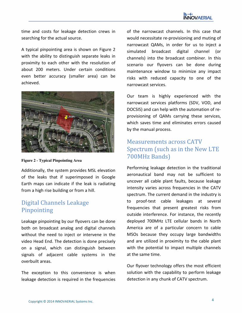
A typical pinpointing area is shown on Figure 2
with the ability to distinguish separate leaks in
proximity to each other with the resolution of
about 200 meters. Under certain conditions
even better accuracy (smaller area) can be
achieved.
Figure 2 - Typical Pinpointing Area
Additionally, the system provides MSL elevation
of the leaks that if superimposed in Google
Earth maps can indicate if the leak is radiating
from a high rise building or from a hill.
Digital Channels Leakage
Pinpointing
Leakage pinpointing by our flyovers can be done
both on broadcast analog and digital channels
without the need to inject or intervene in the
video Head End. The detection is done precisely
on a signal, which can distinguish between
signals of adjacent cable systems in the
overbuilt areas.
The exception to this convenience is when
leakage detection is required in the frequencies
of the narrowcast channels. In this case that
would necessitate re-provisioning and muting of
narrowcast QAMs, in order for us to inject a
simulated broadcast digital channel (or
channels) into the broadcast combiner. In this
scenario our flyovers can be done during
maintenance window to minimize any impact
risks with reduced capacity to one of the
narrowcast services.
Our team is highly experienced with the
narrowcast services platforms (SDV, VOD, and
DOCSIS) and can help with the automation of re-
provisioning of QAMs carrying these services,
which saves time and eliminates errors caused
by the manual process.
Measurements across CATV
Spectrum (such as in the New LTE
700MHz Bands)
Performing leakage detection in the traditional
aeronautical band may not be sufficient to
uncover all cable plant faults, because leakage
intensity varies across frequencies in the CATV
spectrum. The current demand in the industry is
to proof-test cable leakages at several
frequencies that present greatest risks from
outside interference. For instance, the recently
deployed 700MHz LTE cellular bands in North
America are of a particular concern to cable
MSOs because they occupy large bandwidths
and are utilized in proximity to the cable plant
with the potential to impact multiple channels
at the same time.
Our flyover technology offers the most efficient
solution with the capability to perform leakage
detection in any chunk of CATV spectrum.

5 Copyright © 2014 INNOVAERIAL Systems Inc.
Wideband Leakage Measurements
Measurements from a single channel will not
reveal the true extent of the problem as
potential ingress sources might have wider
bandwidth than a single CATV channel. Our
system can provide MSOs with leakage
measurements on multiple adjacent channels or
a composite measurement on any choice of
frequency spans (up to 20MHz). The latter
option, if applied to contiguous span such as an
LTE band, can indicate the true ingress potential
from that specific cellular band.
Work Orders Management Tool
As a means of facilitating our leakage reporting
we have started the development of a work
orders management tool. The goal of the tool is
to aid MSOs in managing work orders for the
repairs of the leakage sources after the flyover
is complete.
The tool will allow management to distribute,
either automatically or manually, work orders
for leakage repairs and monitor any ongoing
repairs. It will also enable field technicians to
view maps and update any assigned work orders
via specially developed smartphone application
(see illustration on Figure 3).
Figure 3
About INNOVAERIAL Systems Inc.
Our company was formed with the objective of
providing a technologically superior, efficient
and more economical electro-magnetic survey
solutions compared to the existing aerial and
ground based methods.
Contact Us
innovaerial.com
+1 855 391 4061