Cat.No.E1E-004-00 JFE COLUMN Apr ... Jakarta 12190, Indonesia Phone : 62-(21 ... the reader’s risk...
17
JFE COLUMN
Transcript of Cat.No.E1E-004-00 JFE COLUMN Apr ... Jakarta 12190, Indonesia Phone : 62-(21 ... the reader’s risk...

JFE COLUMN
Cat.No.E1E-004-00
Apr.,03- 1 -0.5,KCS
Printed in Japan
350 Park Avenue, 27th FI., New York, NY 10022, U.S.A. Phone : 1-(212)310-9320 Fax : 1-(212)308-9292
2000 Town Center, Suite 1900, Southfield, MI 48075, U.S.A. Phone : 1-(248)351-6290 Fax : 1-(248)351-6291
10777 Westheimer, Suite 1010 Houston, TX 77042, U.S.A. Phone : 1-713-532-0052 Fax : 1-713-532-0062
P.O. Box 49168, Three Bentall Centre, 2383-595,BURRARD STREET, VANCOUVER, B.C. V7X 1J1Phone : 1-(604)-687-0091 Fax : 1-(604)-688-7020 Praia de Botafogo 228, Setor B, Salas 508 & 509, CEP 22359-900, Botafogo Phone : 55-(21)2553-1132 Fax : 55-(21)2553-3430
8th Floor, International Press Centre, 76 Shoe Lane, London EC4A 3JB, U.K. Phone : 44-20-7583-1133 Fax : 44-20-7583-1144
16 Raffles Quay, No. 15-03, Hong Leong Building, Singapore 04581 Phone : 65-6220-1174 Fax : 65-6224-8357
Unit C-13A-5, Block-C, Megan Avenue lI. 12, Jalan Yap Kwan Seng, 50450, Kuala Lumpur, MalaysiaPhone : 60-3-2164-6618 Fax : 60-3-2164-6695
22nd Floor, Abdulrahim Place 990, Rama lV Road, Bangkok 10500, ThailandPhone : 66-(2)636-1886 Fax : 66-(2)636-1891
15th Floor Summitmas lI, JI Jendral Sudirman Kav. 61-62, Jakarta 12190, IndonesiaPhone : 62-(21)522-6405 Fax : 62-(21)522-6408
23rd Floor 6788 Ayala Avenue, Oledan Square, Makati City, Metro Manila, PhilippinesPhone : 63-(2)886-7432 Fax : 63-(2)886-7315
Room No.1301, Donghwa Bldg., 58-7 Seosomun-dong, Chung-ku, Seoul 100-110, KoreaPhone : 82-2-779-8246 Fax : 82-2-779-8958
1720, Beijing Fortune Building, Chaoyang District, Beijing 100004, People’s Republic of ChinaPhone : 86-10-6590-9051 Fax : 86-10-6590-9056
Room No.2112, Lippo Plaza, 222 Huai Hai Road(M), Shanghai 200021, People’s Republic of ChinaPhone : 86-(21)5396-5610 Fax : 86-(21)5396-5611
TOKYO HEAD OFFICE
NEW YORK OFFICE
DETROIT OFFICE
HOUSTON OFFICE
VANCOUVER OFFICE
BRAZIL OFFICE
LONDON OFFICE
SINGAPORE OFFICE
MALAYSIA OFFICE
BANGKOK OFFICE
JAKARTA OFFICE
MANILA OFFICE
SEOUL OFFICE
BEIJING OFFICE
SHANGHAI OFFICE
HONG KONG OFFICE 2904, 1Exchange Square, 8 Connaught Place, Central, Hong Kong SARPhone : 85-(2)2537-2176 Fax : 85-(2)2537-5339
Hibiya Kokusai Building, 2-3 Uchisaiwaicho 2-chome, Chiyodaku, Tokyo 100-0011, Japan Phone : 81-(3)3597-3111 Fax : 81-(3)3597-4860
NoticeWhile every effort has been made to ensure the accuracy of the information contained within this publication, the use of the information is at the reader’s risk and no warranty is implied or expressed by JFE Steel Corporation with respect to the use of information contained herein.The information in this publication is subject to change or modification without notice. Please contact the JFE Steel office for the latest information.
Printed on recycled paper.

1 2
Preface
JFE Column products include JFE Column- ER, JFE Column BCR, and JFE Column- BCP.JFE Column ER is a square pipe manufactured by roll forming followed by electric resistance welding in conformity with JIS G 3466 (Carbon Steel Square pipes for General Structural Purposes).
JFE Column BCR is a square pipe manufactured by roll forming and electric resistance welding.JFE Column BCP is a large-diameter, heavy-walled square pipe manufactured by press forming and submerged arc welding.
The latter two, JFE Column BCR and JFE Column- BCP are manufactured based on a new product standard established by the Japan Iron & Steel Federation with the aim of improving performance of structural members of buildings such as weldability and plastic deformation properties required of column materials. Both of these products have received product certification from the Japanese government.
In addition, a new square pipe, JFE Column- BCP325T has been developed. This new product is manufactured by cold press forming and has excellent plastic deformation and earthquake-resistant properties that surpass those of JFE Column- BCP due to markedly improved corner performance.
Users are asked to select the product that is best suited for their particular application.
Features of JFE Column
Manufacturing Process of Steel Products
Production Process of JFE Column and
Available Product Sizes
JFE Column-ER
Product Specifications
Available Sizes and Section Moduli
JFE Column BCR
Product Specifications
Available Sizes and Section Moduli
JFE Column-BCP and JFE Column-BCP 325T
Product Specification : JFE Column-BCP
Product Specification : JFE Column-BCP325T
Differences between JFE Column-BCP325
and JFE Column-BCP325T
Available Sizes and Section Moduli
Available Product Length of JFE Column-BCP
and BCP325T
Precision Cutting and Edge Preparation
of JFE Column-BCP and BCP325T
Piller and Beam Junctions using JFE Columns
2
3
5
7
8
9
10
11
12
13
14
17
17
18
C O N T E N T S
Features of JFE Square Columns Ideal section moduli for columnsExcellent strength for compression, bending, and torsion loads reduces structural weight. Large open floor spaces are prossibleAvailable floor space can be efficiently enlarged using small columns because of their high strength. Eminently suitable for buildings without wall bracesSquare sections have the same strength on the X-and Y-axes, which eliminates the necessity for bracing the Y-axis(weak axis) as is required for H-shape columns. Easy finishing and economical installationThe flat surface provides a smaller surface area for painting, fireproof coating, and interior and exterior material mounting, and facilitates construction. Easy fabrication and clean aperanceThe square section geometry facilitates fabrication and simplifies the installation of beam junctions. Good appearance, even if uncoatedThe round corners offer a pleasing appearance, even if uncoated. Wide range of sizesJFE Column products are available in a wide range of standard sizes from 200 200 to 1000 1000 .
With a side length of 550mm and thicknesses up to 25mm, these are the largest square sectins among cold roll-formed const-
raction materials in Japan.In addition to these many advantages, JFE Column BCR and JFE Column-BCP, which meet the newly established the Japan Iron and Steel Federation, offer the following features: Approved by the The Japanese govermentJFE Column BCR and JFE Column-BCP can be used with complete confidence, as both have been approved by Japanese government. Improved performance as building structuralmaterialsThese products conform to the new standard of the Japan Iron and Steel Federation, which is intended to improve weldability, plastic deformation performance, and other properties required in building structural materials. In particular, both have demonstrated ample plastic deformation performance for use in columns in a large number of actual-scale bending tests, ensuring even higher reliability in weldability and earthquake resistance.
Features of newly-developed cold press formed square section steel pipe JFE Column-BCP325T Toughness of 100% of the cross-section isguaranteed.Use of high performance material plates with enhanced toughness secures excellent toughness, even after cold working, making it possible to guarantee toughness of 70J in 100% of the cross-section. Possible to design in the same manner as SN material.Combined use of the newly-developed NBFW(Non
Brittle Fracture Welding) method with new BCP325T relieves the design-
related limitations imposed in conventional
p r a c t i c e ; enabling

3 4
Blast furnace : Sintered ore, coke, and other materials are charged from the top, and hot blast is blown from the tuyeres. The coke is burned, and ore is reduced and melted to produce pig iron.Basic Oxygen Furnace : Oxygen is blown into the molten pig iron to remove inpurities, re-sulting in steel of the specified composition.Continuous Casting Machine : Molten steel is continuously solidified directly into salabs.
AP PI RH
VAD VODSoaking pit
Ballast/Granulated slag
Limestone Iron ore
Coal
Iron making
Steel making
Rolling
JFE Column-BCPJFE Column-BCP325T
JFE Column-ERJFE Column-BCR
Hot Strip Mill : Slabs heated in a reheating furnace are continuously rolled by a roughing mill and a finishing mill to become hot rolled coils. Electric Welded Tubular Mill : Hot rolled coils are formed into rectangular tubulars by several sets of rolls and electric resistance welded to produce JFE Column-ER & JFE Column BCR.
Plate Mill : Slabs are heated in a reheating furnace and then hot-rolled for the production of steel plate. Steel plates are cut into the specified size, the edges prepared, and then pressed and formed into shape. The seams are welded form both inside and outside of the joint by a submerged arc welder to produce JFE Column-BCP & JFE Column-BCP325T.
Scrap
Corrosion-protective steel pipe
Hot strip mill
Plate mill
Blast furnace
Continuous casting machine
Basic oxygen furnace
Raw material yard
Sintering machine
Coke oven
Blast furnace
Hot metal
Ladle refiningBasic OxygenFurnace
Electric furnace
Reheatingfurnace
Ingot making Blooming mill
Slab
Billet
Slab
Bloom
Bloom
Bloom roll mill Billet mill
Continuous casting machine
UOE pipe mill Large diameter welded pipe
JFE Column-BCPJFE Column-BCP325TWelding
Electroweldedsteel pipe
Electroweldedsteel pipe mill
Press
JFE Column-ERJFE Column BCR Plastic lining line
Butt-welded tubeButt-welded tube mill
Plate mill
Hot strip mill
Slab
Billet
Reheatingfurnace
Reheatingfurnace
plate
Hot rolledcoil
Cold rolledcoilCold strip mill
Reheatingfurnace
Seamless pipe mill
Cold drawing mill
Tinning line
Galvanizing lineGalvanized coila variety of surface treated steel coilsTin plateTin plate coil
Seamless steel pipe
Color painting line

5 6
JFE Column-BCP / JFE Column-BCP325T
JFE Column-ER / JFE Column-BCR
Raw material coils and plates for JFE columns are manufactured at East Japan Works and West Japan Works with the state-of-the-art equipment and technology under the strict quality control.
Available sizes of JFE column
Dimension(mm)
Thickness (mm)
6 8 9 12 14 16 19 22 25 28 32 36 38 40
Rec
tang
ular
Squ
are
Note : please contact us for items not shown above.
200
250
300
350
400
450
500
550
600
650
700
750
800
850
900
950
1000
700
800
800
900
900
1000
1000
200
250
300
350
400
450
500
550
600
650
700
750
800
850
900
950
1000
600
600
700
650
700
700
800
JFE Column-ER, JFE Column BCRJFE Column BCP ( I seam) , JFE Column BCP325T ( I seam)JFE Column BCP( II seam), JFE Column BCP325T( II seam)
JFE Column BCR is not contained 25mm thickness
Forming High frequency contact resistance welding Sizing Cutting
One seam press Two seam tack welding Column edge preparationOne seam roll forming,
external welding
Straightening
Leveling
Edge milling
(Preforming) (Breakdown) (Cage roll)(Fin Pass)
Forming
High frequency contactresistance welding External bead
cuttingSizing
Cutting (Milling method) Oiling for preservation
Plate edge preparation
One seam
Two seams
Press
Roll forming, External weldingInternal welding
External welding
Tack weldingInternal andexternal welding

B
tr
7 8
A
B
A
A
A
C
A
A
A
A
D
B
A
A
A
C
A
A
A
A
C
B
A
A
A
A
D
C
A
A
A
A
C
A
A
A
A
B
A
A
A
C
A
A
A
D
B
B
A
A
D
C
A
A
A
C
B
A
A
A
D
C
A
A
A
A
D
C
B
A
A
A
D
B
A
A
A
C
B
A
A
S S
S S
S
S
S
65
S
t
r
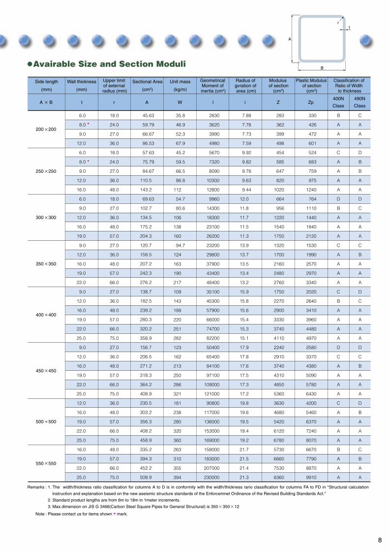
Remarks : 1.
2.
3.
The width/thickness ratio classification for columns A to D is in conformity with the width/thickness rario classification for columns FA to FD in "Structural calculation
instruction and explanation based on the new aseismic structure standards of the Enforcemnet Ordinance of the Revised Building Standards Act."
Standard product lengths are from 6m to 18m in 1meter increments.
Max.dimension on JIS G 3466(Carbon Steel Square Pipes for General Structural) is 350 350 12
Note : Please contact us for items shown * mark.
Avairable Size and Section Moduli
t r A W l i Z Zp400N
Class
490N
ClassA B
Side length
(mm)
Wall thickness
(mm)
Sectional Area
(cm2)
Unit mass
(kg/m)
Upper limit of external radius (mm)
Geometrical Moment of inertia (cm4)
Radius of gvration of area (cm)
Modulus of section
(cm3)
Plastic Modulus of section
(cm3)
Classification of Ratio of Width
to thickness
200 200
250 250
300 300
350 350
400 400
450 450
500 500
550 550
330
426
472
601
524
683
759
975
1240
764
1110
1440
1840
2120
1530
1990
2570
2970
3340
2020
2640
3410
3960
4480
4970
2580
3370
4380
5090
5780
6430
4200
5460
6370
7240
8070
6670
7790
8870
9910
283
362
399
498
454
585
647
820
1020
664
956
1220
1540
1750
1320
1700
2160
2480
2760
1750
2270
2900
3330
3740
4110
2240
2910
3740
4310
4850
5360
3630
4680
5420
6120
6780
5730
6660
7530
8360
7.88
7.78
7.73
7.59
9.92
9.82
9.78
9.63
9.44
12.0
11.8
11.7
11.5
11.3
13.9
13.7
13.5
13.4
13.2
15.9
15.8
15.6
15.4
15.3
15.1
17.9
17.8
17.6
17.5
17.3
17.2
19.8
19.6
19.5
19.4
19.2
21.7
21.5
21.4
21.3
2830
3620
3990
4980
5670
7320
8090
10300
12800
9960
14300
18300
23100
26200
23200
29800
37900
43400
48400
35100
45300
57900
66000
74700
82200
50400
65400
84100
97100
109000
121000
90800
117000
136000
153000
169000
158000
183000
207000
230000
35.8
46.9
52.3
67.9
45.2
59.5
66.5
86.8
54.7
80.6
94.7
112
106
138
160
124
163
190
217
109
143
188
220
251
282
123
162
213
250
286
321
181
238
280
320
360
263
310
355
394
45.63
59.79
66.67
86.53
57.63
75.79
84.67
69.63
110.5
143.2
102.7
134.5
175.2
204.3
120.7
158.5
207.2
242.3
276.2
138.7
182.5
239.2
280.3
320.2
358.9
156.7
206.5
271.2
318.3
364.2
408.9
230.5
303.2
356.3
408.2
458.9
335.2
394.3
452.2
508.9
6.0
8.0
9.0
12.0
6.0
8.0
9.0
12.0
16.0
6.0
9.0
12.0
16.0
19.0
9.0
12.0
16.0
19.0
22.0
9.0
12.0
16.0
19.0
22.0
25.0
9.0
12.0
16.0
19.0
22.0
25.0
12.0
16.0
19.0
22.0
25.0
16.0
19.0
22.0
25.0
18.0
24.0
27.0
36.0
18.0
24.0
27.0
36.0
48.0
18.0
27.0
36.0
48.0
57.0
27.0
36.0
48.0
57.0
66.0
27.0
36.0
48.0
57.0
66.0
75.0
27.0
36.0
48.0
57.0
66.0
75.0
36.0
48.0
57.0
66.0
75.0
48.0
57.0
66.0
75.0
JFE Column-ER
Product Specifications
Dimensional toleranceDimensional tolerance
Mechanical Properties
Chemical Composition
Item and classification
1.0% and 3.0mm
10%
1.0
not specified,
Less than 0.5% of side length, but less than 3mm
1/1500 of total length, max.
1/1250 of total length, max.
Products less than 9m in length
Products 9m or more in length
Thickness
Corner dimension : S
Camber
Length
Angularity made by adjacent flat plate portions
Uneveness of flat portion of each side
Length of side
0
Yield point or Proof stress
(N/mm2)
Tensile strength
(N/mm2)
Elongation
(%)Test piece
Tensile Test
Grade
STKR400
STKR490
245 min.
325 min.
400 min.
490 min.
23 min.
23 min.
No.5
No.5
GradeChemical Composition (%)
MnC Si SP
STKR400 0.040 max. 0.040 max.0.25 max.
STKR490 1.50 max. 0.040 max. 0.040 max.0.55 max.0.18 max.
Thickness (mm), mm, max.3.0
Remarks : 1.
2.
3.
4.
5.
6.
The length of a side, uneveness of flat portion of each side, angularity made by adjacent flat
plate positions and external radius curvature of a corner shall be measured at arbitrary point
excluding 50mm ranges from both ends of a box column.
Flat plate portion is defind as the hatched portion shown in the above figure.
The S dimension that defines the flat plate portion is assumed to be S r,
Where r is the upper limit of the external radius of curvature.
The nueveness of flat plate portion of each side and the angularity made by adjacent flat plate
portions are measured at a location away from weld reinforcement.
The camber tolerance is applicable to the upper to lower bend and right to left bend with a
long pitch.
The thickness tolerance is applied to locations away from any weld reinforcement.
Remarks : 1.
2.
The minimun elongation for JFE Columns with wall thicknesses less than 8 mm shall be calculated by subtracting 1.5% for each 1 mm
decrease in wall thickness below 8 mm from the values of elongation given in the above table, and the result rounded to an integer in
compliance with JIS Z 8401.
The tensile test piece is removed from an area away from the seams.
Remarks : The chemical composition of JFE Column is by ladle analysis.
Note Please contact us for products other than those specified above.
JFE Column-ER is manufactured in conformance with JIS G 3466 (Carbon Steel Square Pipes for General Structural Purposes)
B
tr
7 8
A
B
A
A
A
C
A
A
A
A
D
B
A
A
A
C
A
A
A
A
C
B
A
A
A
A
D
C
A
A
A
A
C
A
A
A
A
B
A
A
A
C
A
A
A
D
B
B
A
A
D
C
A
A
A
C
B
A
A
A
D
C
A
A
A
A
D
C
B
A
A
A
D
B
A
A
A
C
B
A
A
S S
S S
S
S
S
65
S
t
r
Remarks : 1.
2.
3.
The width/thickness ratio classification for columns A to D is in conformity with the width/thickness rario classification for columns FA to FD in "Structural calculation
instruction and explanation based on the new aseismic structure standards of the Enforcemnet Ordinance of the Revised Building Standards Act."
Standard product lengths are from 6m to 18m in 1meter increments.
Max.dimension on JIS G 3466(Carbon Steel Square Pipes for General Structural) is 350 350 12
Note : Please contact us for items shown * mark.
Avairable Size and Section Moduli
t r A W l i Z Zp400N
Class
490N
ClassA B
Side length
(mm)
Wall thickness
(mm)
Sectional Area
(cm2)
Unit mass
(kg/m)
Upper limit of external radius (mm)
Geometrical Moment of inertia (cm4)
Radius of gvration of area (cm)
Modulus of section
(cm3)
Plastic Modulus of section
(cm3)
Classification of Ratio of Width
to thickness
200 200
250 250
300 300
350 350
400 400
450 450
500 500
550 550
330
426
472
601
524
683
759
975
1240
764
1110
1440
1840
2120
1530
1990
2570
2970
3340
2020
2640
3410
3960
4480
4970
2580
3370
4380
5090
5780
6430
4200
5460
6370
7240
8070
6670
7790
8870
9910
283
362
399
498
454
585
647
820
1020
664
956
1220
1540
1750
1320
1700
2160
2480
2760
1750
2270
2900
3330
3740
4110
2240
2910
3740
4310
4850
5360
3630
4680
5420
6120
6780
5730
6660
7530
8360
7.88
7.78
7.73
7.59
9.92
9.82
9.78
9.63
9.44
12.0
11.8
11.7
11.5
11.3
13.9
13.7
13.5
13.4
13.2
15.9
15.8
15.6
15.4
15.3
15.1
17.9
17.8
17.6
17.5
17.3
17.2
19.8
19.6
19.5
19.4
19.2
21.7
21.5
21.4
21.3
2830
3620
3990
4980
5670
7320
8090
10300
12800
9960
14300
18300
23100
26200
23200
29800
37900
43400
48400
35100
45300
57900
66000
74700
82200
50400
65400
84100
97100
109000
121000
90800
117000
136000
153000
169000
158000
183000
207000
230000
35.8
46.9
52.3
67.9
45.2
59.5
66.5
86.8
54.7
80.6
94.7
112
106
138
160
124
163
190
217
109
143
188
220
251
282
123
162
213
250
286
321
181
238
280
320
360
263
310
355
394
45.63
59.79
66.67
86.53
57.63
75.79
84.67
69.63
110.5
143.2
102.7
134.5
175.2
204.3
120.7
158.5
207.2
242.3
276.2
138.7
182.5
239.2
280.3
320.2
358.9
156.7
206.5
271.2
318.3
364.2
408.9
230.5
303.2
356.3
408.2
458.9
335.2
394.3
452.2
508.9
6.0
8.0
9.0
12.0
6.0
8.0
9.0
12.0
16.0
6.0
9.0
12.0
16.0
19.0
9.0
12.0
16.0
19.0
22.0
9.0
12.0
16.0
19.0
22.0
25.0
9.0
12.0
16.0
19.0
22.0
25.0
12.0
16.0
19.0
22.0
25.0
16.0
19.0
22.0
25.0
18.0
24.0
27.0
36.0
18.0
24.0
27.0
36.0
48.0
18.0
27.0
36.0
48.0
57.0
27.0
36.0
48.0
57.0
66.0
27.0
36.0
48.0
57.0
66.0
75.0
27.0
36.0
48.0
57.0
66.0
75.0
36.0
48.0
57.0
66.0
75.0
48.0
57.0
66.0
75.0
JFE Column-ER
Product Specifications
Dimensional toleranceDimensional tolerance
Mechanical Properties
Chemical Composition
Item and classification
1.0% and 3.0mm
10%
1.0
not specified,
Less than 0.5% of side length, but less than 3mm
1/1500 of total length, max.
1/1250 of total length, max.
Products less than 9m in length
Products 9m or more in length
Thickness
Corner dimension : S
Camber
Length
Angularity made by adjacent flat plate portions
Uneveness of flat portion of each side
Length of side
0
Yield point or Proof stress
(N/mm2)
Tensile strength
(N/mm2)
Elongation
(%)Test piece
Tensile Test
Grade
STKR400
STKR490
245 min.
325 min.
400 min.
490 min.
23 min.
23 min.
No.5
No.5
GradeChemical Composition (%)
MnC Si SP
STKR400 0.040 max. 0.040 max.0.25 max.
STKR490 1.50 max. 0.040 max. 0.040 max.0.55 max.0.18 max.
Thickness (mm), mm, max.3.0
Remarks : 1.
2.
3.
4.
5.
6.
The length of a side, uneveness of flat portion of each side, angularity made by adjacent flat
plate positions and external radius curvature of a corner shall be measured at arbitrary point
excluding 50mm ranges from both ends of a box column.
Flat plate portion is defind as the hatched portion shown in the above figure.
The S dimension that defines the flat plate portion is assumed to be S r,
Where r is the upper limit of the external radius of curvature.
The nueveness of flat plate portion of each side and the angularity made by adjacent flat plate
portions are measured at a location away from weld reinforcement.
The camber tolerance is applicable to the upper to lower bend and right to left bend with a
long pitch.
The thickness tolerance is applied to locations away from any weld reinforcement.
Remarks : 1.
2.
The minimun elongation for JFE Columns with wall thicknesses less than 8 mm shall be calculated by subtracting 1.5% for each 1 mm
decrease in wall thickness below 8 mm from the values of elongation given in the above table, and the result rounded to an integer in
compliance with JIS Z 8401.
The tensile test piece is removed from an area away from the seams.
Remarks : The chemical composition of JFE Column is by ladle analysis.
Note Please contact us for products other than those specified above.
JFE Column-ER is manufactured in conformance with JIS G 3466 (Carbon Steel Square Pipes for General Structural Purposes)

9 10
B
tr
H B R A W It
200
250
300
350
400
450
500
550
200
250
300
350
400
450
500
550
15
20
22.5
30
15
20
22.5
30
35
40
15
20
22.5
30
35
40
47.5
22.5
30
35
40
47.5
55
22.5
30
35
40
47.5
55
22.5
30
35
40
47.5
55
30
35
40
47.5
55
40
47.5
55
6
8
9
12
6
8
9
12
14
16
6
8
9
12
14
16
19
9
12
14
16
19
22
9
12
14
16
19
22
9
12
14
16
19
22
12
14
16
19
22
16
19
22
45.32
59.24
65.98
85.30
57.32
75.24
83.98
69.32
91.24
109.3
125.4
141.0
102.0
133.3
153.4
173.0
201.2
120.0
157.3
181.4
205.0
239.2
272.0
138.0
181.3
209.4
237.0
277.2
316.0
156.0
205.3
237.4
269.0
315.2
360.0
229.3
265.4
301.0
353.2
404.0
333.0
391.2
448.0
35.6
46.5
51.8
67.0
45.0
59.1
65.9
85.8
98.5
54.4
71.6
80.1
94.2
111
105
120
136
158
123
142
161
188
214
108
142
164
186
218
248
122
161
186
211
247
283
180
208
236
277
317
261
307
352
2,800
3,570
3,920
4,860
5,620
7,230
7,980
10,100
11,300
12,400
9,890
12,800
14,200
18,100
20,400
22,600
25,500
23,000
29,400
33,400
37,200
42,400
47,100
34,800
44,800
51,100
57,100
65,400
73,000
50,100
64,800
74,100
82,900
95,500
107,000
90,000
103,000
116,000
134,000
150,000
156,000
181,000
204,000
280
357
392
486
450
578
639
805
903
992
660
853
946
1,200
1,360
1,510
1,700
1,310
1,680
1,910
2,130
2,420
2,690
1,740
2,240
2,560
2,850
3,270
3,650
2,230
2,880
3,290
3,690
4,240
4,760
3,600
4,120
4,630
5,340
6,010
5,670
6,570
7,420
327
421
465
588
521
676
750
959
1,090
1,210
760
991
1,100
1,420
1,620
1,810
2,070
1,520
1,970
2,260
2,530
2,910
3,270
2,010
2,610
3,000
3,370
3,900
4,390
2,560
3,340
3,840
4,330
5,020
5,680
4,160
4,790
5,410
6,290
7,130
6,610
7,700
8,750
33.3
25.0
22.2
16.7
41.7
31.3
27.8
20.8
17.9
15.6
50.0
37.5
33.3
25.0
21.4
18.8
15.8
38.9
29.2
25.0
21.9
18.4
15.9
44.4
33.3
28.6
25.0
21.1
18.2
50.0
37.5
32.1
28.1
23.7
20.5
41.7
35.7
31.3
26.3
22.7
34.4
28.9
25.0
B
A
A
A
C
B
A
A
A
A
D
C
B
A
A
A
A
C
A
A
A
A
A
D
B
A
A
A
A
D
C
B
A
A
A
C
C
B
A
A
C
A
A
7.86
7.76
7.71
7.55
9.90
9.80
9.75
9.59
9.49
9.38
11.9
11.8
11.8
11.6
11.5
11.4
11.3
13.8
13.7
13.6
13.5
13.3
13.2
15.9
15.7
15.6
15.5
15.4
15.2
17.9
17.8
17.7
17.6
17.4
17.2
19.8
19.7
19.6
19.4
19.3
21.6
21.5
21.3
Dimensions
(mm)
Sectional Area
(cm2)
Unit Mass
(kg/m)
Geometrical Moment of inertia (cm4)
i
Radius of gyration of area
(cm)
Z
Modulus of section
(cm3)
Zp H/t
Plastic Modulus of section
(cm3)
Ratio of Width to thickness
Classification of Ratio of Width
to thickness
BCR295
Avairable Size and Section Moduli
Remarks : 1.
2.
The width/thickness ratio classification for columns A to D is in conformity with the width/thickness ratio calssification for columns FA to FD in "Structural calculation
instruction and explanation based on the new aseismic structure standards of the Enforcement Ordinance of the Revised Building Standards Act."
Standard product lengths are from 6m to 18m in 1 meter increments.
Remarks : 1.
2.
3.
Unevenness of the flat portion, angularity between adjacent flat portions, and thickness tolerances apply to
all parts except weld reinforcement areas.
The radius of curvature means the radius of curvature at the point of intersection of the exterior sides of the
corner and lines at 45 to the adjacent side and is measured in the range of 65 around the center of
intersection.
Camber tolerance is applicable to the apper to lower bend and right to lift bend with a long pitch.
Remarks : 1.
2.
For wall thicknesses of less than 8mm, the minimum elongation is calculated by subtracting 1.5% form the value shown above for each
1 mm reduction in thickness, rounded to the nearest whole number in accordance with JIS Z 8401.
Charpy absorbed energy is tested at flat plate areas, excluding welded surface of square hollow sections with thicknesses exceeding
12mm. Test pieces are JIS No.4, taken in longitudinal direction.
Remarks : 1.
2.
3.
Note : Please contact us for items shown * mark.
JFE Column BCR is manufactured in accordance with the standards of The Japan Iron and Steel Federation.
When necessary, addition of alloying elements other than the above is possible.
Assuming a free N content of 0.006% or less, an N content of 0.009% is possible.
With the agreenent of the parties concerned, weld crack sensitivity composition can be applied in place of the carbon equivalent(Ceq).
H
JFE Column-BCR
Product Specifications
Dimensional toleranceDimensional tolerance
Mechanical Properties
Chemical Composition
Item and classification
1.0% and 3.0mm
1.0
not specified
0.3 1.0mm
0.3 1.2mm
Less than 0.5% of side length, but less than 3mm
1/1500 of total length, max.
1/1250 of total length, max.
6mm or more, less than 16mm
Product length less than 9m
Product length 9m or more
16mm or more, up to 22mmThickness
Torsion
Camber
Length
Angularity made by adjacent flat plate portions
Uneveness of flat portion of each side
Length of side
Angular radius of curvature
Length of side(mm)/1000
Total length(m), mm, max.
1.5
0,
(2.5 0.5) Thickness(mm)
r
t65
Thickness (mm)
Yield point or
Proof stress (N/mm2)
Tensile strength (N/mm2)
Yield ratio (%) Elongation
(%)
Elongation Charpy absorbed energy
Test pieceTest
Temperature(C )
Absorbed Energy
(J)
Grade
BCR295 12 t 16
295 min.
295 min.
445 max.
400 min.
550 max.
23 min.
27 min.16 t 2290 max.
No.5 0 27 min.
GradeChemical Composition (%) Carbon
Equivalent (%)
Weld crack Sensitivity
Composition (%)
BCR295
MnC Si S NP
1.40 max. 0.030 max. 0.015 max. 0.006 max.0.35 max.0.20 max. 0.36 max. 0.26 max.
Ceq (%) C Mn/6 Si/24 Ni/40 Cr/5 Mo/4 V/14Weld crack sensitivity composition (%) C Si/30 Mn/20 Cu/20 Ni/60 Cr/20 Mo/15 V/10 5B
6 t 12
Note Please contact us for products other than those specified above.

11 12
Product Specifications
Product Specifications
JFE Column BCP is manufactured in accordance with the standards of The Japan Iron and Steel Federation.
JFE Column-BCP JFE Column-BCP325T
Dimensional toleranceDimensional tolerance
Mechanical Properties
Chemical Composition
Item and classification
1.0% and 3.0mm
1.0
not specified
0.3 1.0mm
0.3 1.2mm
0.3 1.3mm
Less than 0.5% of side length, but less than 3mm
1/1500 of total length, max.
1/1250 of total length, max.
12mm or more, less than 16mm
Product length less than 9m
Product length 9m or more
16mm or more, less than 25mm
12mm or more, less than 19mm
over 19mm, up to 40mm
25mm or more, up to 40mm
Thickness
Torsion
Camber
Length
Angularity made by adjacent flat plate portions
Uneveness of flat portion of each side
Length of side
Angular radius of curvature
Length of side(mm)/1000
Total length(m), mm, max.
1.5
0,
(3.5 0.5) Thickness(mm)
(3.5 0.4) Thickness(mm)
r
t65
Thickness (mm)
Yield point or
Proof stress (N/mm2)
Tensile strength (N/mm2)
Yield ratio (%) Elongation
(%)
Elongation Charpy absorbed energy
Test pieceTest
Temperature(C )
Absorbed Energy
(J)
Grade
BCP325T12 t 16
16 t 40
325 min.
445 max.
490 min.
610 max.
17 min.
21 min.80 max. No.1A 0 70 min.
GradeChemical Composition (%) Carbon
Equivalent (%)
Weld crack Sensitivity
Composition (%)
BCP325T
MnC Si S NP
1.60 max. 0.020 max. 0.005 max. 0.006 max.0.55 max.0.18 max. 0.44 max. 0.29 max.
Dimensional toleranceDimensional tolerance
Mechanical Properties
Chemical Composition
Item and classification
1.0% and 3.0mm
1.0
0
0.3 1.0mm
0.3 1.2mm
0.3 1.3mm
Less than 0.5% of side length, but less than 3mm
1/1500 of total length, max.
1/1250 of total length, max.
12mm or more, less than 16mm
Product length less than 9m
Product length 9m or more
16mm or more, less than 25mm
12mm or more, less than 19mm
over 19mm, less than 40mm
25mm or more, up to 40mm
Thickness
Torsion
Camber
Length
Angularity made by adjacent flat plate portions
Uneveness of flat portion of each side
Length of side
Angular radius of curvature
Length of side(mm)/1000
Total length(m), mm, max.
1.5
(3.5 0.5) Thickness(mm)
(3.5 0.4) Thickness(mm)
r
t65
Thickness (mm)
Yield point or
Proof stress (N/mm2)
Tensile strength (N/mm2)
Yield ratio (%) Elongation
(%)
Elongation Charpy absorbed energy
Test pieceTest
Temperature(C )
Absorbed Energy
(J)
Grade
BCP235
BCP325
235 min.
235 min.
355 max.
325 min.
325 min.
445 max.
400 min.
510 max.
490 min.
610 max.
18 min.
22 min.
17 min.
21 min.
80 max.
80 max.
No.1A 0 27 min.
GradeChemical Composition (%) Carbon
Equivalent (%)
Weld crack Sensitivity
Composition (%)MnC Si S NP
1.40 max.
0.60 min.
0.020 max. 0.008 max.
0.030 max. 0.015 max.
0.030 max. 0.015 max.
0.020 max. 0.008 max.
0.006 max.0.35 max.0.20 max.
1.60 max.0.55 max.0.18 max.
0.36 max. 0.26 max.
0.006 max. 0.44 max. 0.29 max.
not specified,
BCP235(SN400B)
BCP235(SN400C)
BCP325(SN490B)
BCP325(SN490C)
16 t 40
12 t 16
6 t 12
16 t 40
12 t 16
6 t 12
Remarks : 1. When necessary, addition of alloying elements other than the above is possible.
2. Assuming a free N content of 0.006% or less, an N content of 0.009% is possible.
3. With the agreement of the parties concerned, weld crack sensitivity composition can be applied in place of the carbon equivalent (Ceq).
Weld crack sensitivity composition (%) C Si/30 Mn/20 Cu/20 Ni/60 Cr/20 Mo/15 V/10 5B
Ceq (%) C Mn/6 Si/24 Ni/40 Cr/5 Mo/4 V/14
Remarks : 1.
2.
For wall thicknesses of less than 8mm, the minimum elongation is calculated by subtracting 1.5% form the value shown above for each
1 mm reduction in thickness, rounded to the nearest whole number in accordance with JIS Z 8401.
Charpy absorbed energy is tested at flat plate areas, excluding welded surface of square hollow sections with thicknesses exceeding
12mm. Test pieces are JIS No.4, taken in longitudinal direction.
Remarks : 1.
2.
3.
Unevenness of the flat portion, angularity between adjacent flat portions, and thickness tolerances apply to
all parts except weld reinforcement areas.
The radius of curvature means the radius of curvature at the point of intersection of the exterior sides of the
corner and lines at 45 to the adjacent side and is measured in the range of 65 around the center of
intersection.
Camber tolerance is applicable to the upper to lower bend and right to lift bend with a long pitch.
Note Please contact us for products other than those specified above. Note Please contact us for products other than those specified above.
Remarks : 1.
2.
Ceq (%) C Mn/6 Si/24 Ni/40 Cr/5 Mo/4 V/14
3. HAZ toughness index in MAG welding (%) C Mn/8 6 (P S) 12N 4TiWeld crack sensitivity composition (%) C Si/30 Mn/20 Cu/20 Ni/60 Cr/20 Mo/15 V/10 5B
However N total N, When Ti 0.005%, consider Ti 0
When necessary, addition of alloying elements other than the above is possible.
With the agreement of the parties concerned, weld crack sensitivity composition can be applied in place of the carbon equivalent(Ceq).
Remarks : 1.
2.
Charpy absorbed energy is tested at flat area and corner. Test pieces are JIS No.4, taken is the longitudinal direction.
Test pieces of Charpy absorbed energy are permissible to use the sub-size piece of 7.5mm width, when can not be taken the full size.
When, Absorbed energy 52J
Remarks : 1.
2.
Unevenness of the flat portion, angularity between adjacent flat portions, and thickness tolerances apply to
all parts except weld reinforcement areas.
The radius of curvature means the radius of curvature at the point of intersection of the exterior sides of the
corner and lines at 45 to the adjacent side and is measured in the range of 65 around the center of
intersection.

13 14
Square SectionAvairable Sizes and Section ModuliDifferences between BCP325 and BCP325T
BB
ttrr
HH
H B R W It
400
450
500
550
600
650
700
400
450
500
550
600
650
700
66.5
77
87.5
66.5
77
87.5
98
56
66.5
77
87.5
98
56
66.5
77
87.5
98
56
66.5
77
87.5
98
56
66.5
77
87.5
98
56
66.5
77
87.5
98
112
112
112
126
133
140
112
126
133
140
112
126
133
140
112
126
133
140
19
22
25
19
22
25
28
32
16
19
22
25
28
32
16
19
22
25
28
32
36
38
40
16
19
22
25
28
32
36
38
40
16
19
22
25
28
32
36
38
40
16
19
22
25
28
32
36
38
40
213
242
269
243
276
308
339
379
233
272
311
348
383
429
258
302
345
387
427
479
529
553
576
283
332
380
426
471
529
585
612
639
308
362
414
465
515
580
642
672
702
333
392
449
505
559
630
698
732
764
62,800
69,500
75,400
92,200
103,000
112,000
121,000
130,000
113,000
130,000
145,000
159,000
172,000
187,000
153,000
176,000
197,000
217,000
236,000
258,000
277,000
286,000
294,000
201,000
232,000
261,000
288,000
314,000
345,000
372,000
385,000
397,000
258,000
299,000
337,000
374,000
407,000
449,000
487,000
505,000
521,000
325,000
378,000
427,000
474,000
518,000
573,000
623,000
646,000
669,000
3,140
3,480
3,770
4,100
4,560
4,980
5,360
5,780
4,510
5,180
5,800
6,360
6,870
7,470
5,550
6,390
7,180
7,900
8,570
9,380
10,100
10,400
10,700
6,690
7,730
8,710
9,620
10,500
11,500
12,400
12,800
13,200
7,940
9,200
10,400
11,500
12,500
13,800
15,000
15,500
16,000
9,300
10,800
12,200
13,500
14,800
16,400
17,800
18,500
19,100
3,770
4,220
4,640
4,880
5,490
6,050
6,580
7,210
5,290
6,130
6,920
7,660
8,360
9,210
6,480
7,530
8,520
9,460
10,300
11,400
12,400
12,900
13,400
7,790
9,070
10,300
11,400
12,500
13,900
15,200
15,800
16,400
9,220
10,700
12,200
13,600
14,900
16,600
18,200
19,000
19,700
10,800
12,600
14,300
16,000
17,600
19,600
21,500
22,400
23,300
15.2
15.0
14.8
17.3
17.1
16.9
16.7
16.4
19.5
19.3
19.1
18.9
18.8
18.5
21.5
21.4
21.2
21.0
20.8
20.6
20.3
20.2
20.0
23.6
23.4
23.2
23.1
22.9
22.6
22.4
22.2
22.1
25.6
25.5
25.3
25.1
24.9
24.7
24.4
24.3
24.1
27.7
27.5
27.3
27.1
27.0
26.7
26.5
26.3
26.2
Dimensions
(mm)
A
271.0
307.7
342.8
309.0
351.7
392.8
432.3
482.3
296.6
347.0
395.7
442.8
488.3
546.3
328.6
385.0
439.7
492.8
544.3
610.3
673.4
703.9
733.6
360.6
423.0
483.7
542.8
600.3
674.3
745.4
779.9
813.6
392.6
461.0
527.7
592.8
656.3
738.3
817.4
855.9
893.6
424.6
499.0
571.7
642.8
712.3
802.3
889.4
931.9
973.6
Sectional Area
(cm2)
Unit Mass
(kg/m)
Geometrical moment
of inertia (cm4)
i
Radius of Gyration
of area (cm)
Z
Modulus of section
(cm3)
Zp
Plastic Modulus of
section (cm3)
21.1
18.2
16.0
23.7
20.5
18.0
16.1
14.1
31.3
26.3
22.7
20.0
17.9
15.6
34.4
28.9
25.0
22.0
19.6
17.2
15.3
14.5
13.8
37.5
31.6
27.3
24.0
21.4
18.8
16.7
15.8
15.0
40.6
34.2
29.5
26.0
23.2
20.3
18.1
17.1
16.3
43.8
36.8
31.8
28.0
25.0
21.9
19.4
18.4
17.5
H/t
Ratio of Width to thickness
Classification of Ratio of Width to
thickness
A
A
A
A
A
A
A
A
A
A
A
A
A
A
B
A
A
A
A
A
A
A
A
C
A
A
A
A
A
A
A
A
C
B
A
A
A
A
A
A
A
C
B
A
A
A
A
A
A
A
BCP235
A
A
A
A
A
A
A
A
B
A
A
A
A
A
C
B
A
A
A
A
A
A
A
C
B
B
A
A
A
A
A
A
C
C
B
A
A
A
A
A
A
D
C
B
B
A
A
A
A
A
BCP325
BCP325T
Two seamOne seam
note : Indicate two seamed products
* HAZ toughness index in MAG welding conforms to "Development of New Steel Structure Building System Using Advanced
Technology" and "Establishment of Performance Evaluation Method for Welding Materials and Welded Joints in Building Structures"
final reports (Architectural Laboratories, Japan Iron and Steel Federation, Welding Society).
1. Chemical composition
2. Corner toughness guarantee
3. Guidance for execution of diaphragm weld by welding execution procedure
4. Chemical composition index for securing HAZ toughness
5. Available size range (applcable plate thickness)
6. Design method (Reference: See Cold Formed Square Section Steel Pipe Design and Execution Manual.)
P0.030 max.
S0.015 max.
N0.006 max.
(%)
P0.020 max.
S0.005 max.
N0.006 max.
(%)
WeldMetal
HAZ
Flange
Diap
hragm
CrackCrack propagation direction
Crack propagation direction
WeldMetal
HAZ
Flange
Diap
hragm
Crack
However, if the free N content is reduced to 0.006% or less by addition of Al or other N-fixing element, N contents as high as 0.009% are permissible.
No provisionWith conventional welding methods, in particular, there was a large danger of brittle fracture by the crack propagation route shown in the following figure.
No provision
No provision
6 mm or more.
Route1Internal diaphragm seismic stress increase coefficient 1.1External and through diaphragm seismic stress increase coefficient 1.1 Route2Column-beam yield strength rario 1.5 Route3Internal diaphragm column yield strength reduction factor 0.85External and through diaphragm column yield strength reduction factor 0.80
Shows total N content. Relaxation of N requirement as in conventional BCP is not permissible
Guarantee that vEo 70J using Charpy impact test piece taken from column corner.
Even if cracking is initiated, the crack does not propagate in the embrittled zone along the groove.Depending on the material, ductile fracture may occur.In addition, recommended welding conditions are shown.
HAZ toughness index in MAG welding fHAZ 0.58%
However, N total N.When Ti 0.005%, consider Ti 0.
Route1Internal diaphragm seismic stress increase coefficient 1.0External and through diaphragm seismic stress increase coefficient 1.0 Route2Study of column-beam yield strength ratio not required. Route3Internal diaphragm column yield strength reduction factor 1.00External and through diaphragm column yield strength reduction factor 1.00Accordingly, it is possible to design in the same manner as with welded four side box columns and hot formed square section seteel pipes.
12 mm or more
*HAZ toughness index in MAG weldingfHAZ C Mn/8 6(P S) 12N 4Ti
JFE Column-BCP/JFE Column-BCP325T
BCP325TConventional BCP

15 16
H B R W Ixt
700
800
800
900
900
1000
1000
600
600
700
650
700
700
800
66.5
77
87.5
98
66.5
77
87.5
98
66.5
77
87.5
98
66.5
77
87.5
98
66.5
77
87.5
98
77
87.5
98
77
87.5
98
112
126
133
140
112
126
133
140
112
126
133
140
112
126
133
140
112
126
133
140
112
126
133
140
112
126
133
140
19
22
25
28
32
36
38
40
19
22
25
28
32
36
38
40
19
22
25
28
32
36
38
40
19
22
25
28
32
36
38
40
19
22
25
28
32
36
38
40
22
25
28
32
36
38
40
22
25
28
32
36
38
40
362
414
465
515
580
642
672
702
392
449
505
559
630
698
732
764
422
483
544
603
680
755
791
827
436
501
563
625
705
783
821
859
541
518
583
647
730
811
851
890
552
622
691
781
868
911
953
587
662
735
831
942
970
1,016
333,000
376,000
417,000
455,000
501,000
544,000
563,000
582,000
458,000
518,000
575,000
628,000
695,000
756,000
784,000
811,000
516,000
585,000
650,000
712,000
789,000
861,000
894,000
926,000
644,000
731,000
813,000
891,000
989,000
1,080,000
1,120,000
1,160,000
681,000
773,000
861,000
944,000
1,050,000
1,150,000
1,190,000
1,240,000
995,000
1,110,000
1,220,000
1,360,000
1,480,000
1,550,000
1,600,000
1,100,000
1,230,000
1,350,000
1,510,000
1,650,000
1,720,000
1,790,000
Iy
264,000
298,000
330,000
360,000
396,000
430,000
445,000
460,000
296,000
335,000
371,000
406,000
448,000
487,000
505,000
522,000
422,000
478,000
531,000
581,000
644,000
702,000
730,000
756,000
393,000
446,000
496,000
543,000
602,000
657,000
683,000
707,000
466,000
528,000
588,000
644,000
716,000
782,000
813,000
843,000
579,000
645,000
708,000
787,000
861,000
896,000
930,000
784,000
875,000
962,000
1,070,000
1,180,000
1,230,000
1,270,000
9,530
10,800
11,900
13,000
14,300
15,500
16,100
16,600
11,500
13,000
14,400
15,700
17,400
18,900
19,600
20,300
12,900
14,600
16,200
17,800
19,700
21,500
22,400
23,200
14,300
16,200
18,100
19,800
22,000
24,000
24,900
25,800
15,100
17,200
19,100
21,000
23,300
25,500
26,500
27,500
19,900
22,200
24,400
27,100
29,700
30,900
32,100
22,000
24,600
27,000
30,100
33,000
34,400
35,800
11,300
12,800
14,300
15,700
17,400
19,100
19,900
20,600
13,700
15,600
17,400
19,100
21,300
23,400
24,400
25,300
15,200
17,300
19,300
21,300
23,800
26,100
27,200
28,300
17,100
19,500
21,800
24,000
26,900
29,500
30,800
32,100
17,900
20,500
22,900
25,200
28,200
31,100
32,500
33,800
23,900
26,700
29,500
33,100
36,500
38,100
39,700
26,000
29,200
32,200
36,200
39,900
41,700
43,500
26.9
26.7
26.5
26.3
26.1
25.8
25.6
25.5
30.3
30.1
29.9
29.7
29.4
29.1
29.0
28.9
31.0
30.8
30.6
30.4
30.2
29.9
29.8
29.7
34.0
33.9
33.7
33.4
33.2
32.9
32.8
32.6
34.4
34.2
34.0
33.8
33.6
33.3
33.2
33.0
37.6
37.4
37.2
36.9
36.6
36.5
36.4
38.4
38.2
38.0
37.7
37.5
37.3
37.2
Dimensions
(mm)
A
461.0
527.7
592.8
656.3
738.3
817.4
856.0
893.6
499.0
571.7
642.8
712.3
802.3
889.4
931.9
973.6
537.0
615.7
692.8
768.3
866.3
961.4
556.0
637.7
717.8
796.3
898.3
997.4
575.0
659.7
742.8
824.3
930.3
703.7
792.8
880.3
994.3
747.7
842.8
936.3
1,008
1,054
1,046
1,094
1,033
1,084
1,134
1,105
1,160
1,214
1,058
1,177
1,236
1,294
Sectional Area(cm2)
Unit Mass(kg/m)
Geometrical Moment of inertia
(cm4)
ix
23.9
23.8
23.6
23.4
23.2
22.9
22.8
22.7
24.4
24.2
24.0
23.9
23.6
23.4
23.3
23.2
28.0
27.9
27.7
27.5
27.3
27.0
26.9
26.8
26.6
26.4
26.3
26.1
25.9
25.7
25.5
25.4
28.5
28.3
28.1
28.0
27.7
27.5
27.4
27.3
28.7
28.5
28.4
28.1
27.9
27.8
27.7
32.4
32.2
32.1
31.8
31.6
31.5
31.4
iy
Radius of Gyration of area
(cm)
Zx
8,800
9,930
11,000
12,000
13,200
14,300
14,800
15,300
9,870
11,200
12,400
13,500
14,900
16,200
16,800
17,400
12,000
13,600
15,200
16,600
18,400
20,100
20,900
21,600
12,100
13,700
15,300
16,700
18,500
20,200
21,000
21,800
13,300
15,100
16,800
18,400
20,400
22,300
23,200
24,100
16,500
18,400
20,200
22,500
24,600
25,600
26,600
19,600
21,900
24,100
26,800
29,400
30,600
31,800
Zy
Modurus of section
(cm3)
Zpx
10,200
11,600
12,900
14,100
15,700
17,200
17,900
18,600
11,300
12,800
14,300
15,700
17,600
19,300
20,100
20,800
13,900
15,800
17,700
19,400
21,700
23,900
24,900
25,900
13,700
15,700
17,500
19,300
21,600
23,700
24,800
25,800
15,200
17,300
19,300
21,300
23,900
26,300
27,400
28,600
18,800
21,000
23,200
26,000
28,700
29,900
31,200
22,400
25,100
27,700
31,100
34,400
35,900
37,500
Zpy
Plastic Modulus of section
(cm3)
36.8
31.8
28.0
25.0
21.9
19.4
18.4
17.5
42.1
36.4
32.0
28.6
25.0
22.2
21.1
20.0
42.1
36.4
32.0
28.6
25.0
22.2
21.1
20.0
47.4
40.9
36.0
32.1
28.1
25.0
23.7
22.5
47.4
40.9
36.0
32.1
28.1
25.0
23.7
22.5
45.5
40.0
35.7
31.3
27.8
26.3
25.0
45.5
40.0
35.7
31.3
27.8
26.3
25.0
H/t
Ratio of Width to thickness
Classification of Ratio of Width to
thickness
B
A
A
A
A
A
A
A
C
B
A
A
A
A
A
A
C
B
A
A
A
A
A
A
C
C
B
A
A
A
A
A
C
C
B
A
A
A
A
A
C
C
B
A
A
A
A
C
C
B
A
A
A
A
BCP235
C
B
B
A
A
A
A
A
D
C
B
B
A
A
A
A
D
C
B
B
A
A
A
A
D
C
C
C
B
A
A
A
D
C
C
C
B
A
A
A
D
C
C
B
B
A
A
D
C
C
B
B
A
A
BCP325
BCP325TH B R W It
750
800
850
900
950
1000
750
800
850
900
950
1000
66.5
77
87.5
98
66.5
77
87.5
98
66.5
77
87.5
98
66.5
77
87.5
98
77
87.5
98
77
87.5
98
112
126
133
140
112
126
133
140
112
126
133
140
112
126
133
140
112
126
133
140
112
126
133
140
19
22
25
28
32
36
38
40
19
22
25
28
32
36
38
40
19
22
25
28
32
36
38
40
19
22
25
28
32
36
38
40
22
25
28
32
36
38
40
22
25
28
32
36
38
40
422
483
544
603
680
755
791
827
451
518
583
647
730
811
851
890
481
552
622
691
781
868
911
953
511
587
662
735
831
924
970
1,016
622
701
779
881
981
1,030
1,078
656
740
823
931
1,037
1,090
1,141
469,000
531,000
591,000
647,000
717,000
782,000
813,000
842,000
574,000
651,000
725,000
795,000
884,000
966,000
1,000,000
1,040,000
694,000
788,000
879,000
965,000
1,070,000
1,180,000
1,220,000
1,270,000
829,000
943,000
1,050,000
1,160,000
1,290,000
1,420,000
1,480,000
1,530,000
1,120,000
1,250,000
1,370,000
1,530,000
1,680,000
1,760,000
1,830,000
1,310,000
1,470,000
1,610,000
1,810,000
1,990,000
2,070,000
2,160,000
12,500
14,200
15,700
17,200
19,100
20,900
21,700
22,400
14,300
16,300
18,100
19,900
22,100
24,100
25,100
26,100
16,300
18,500
20,700
22,700
25,300
27,700
28,800
29,900
18,400
21,000
23,400
25,700
28,700
31,500
32,800
34,100
23,500
26,300
28,900
32,300
35,500
37,000
38,500
26,200
29,300
32,300
36,100
39,700
41,500
43,100
14,500
16,600
18,500
20,400
22,800
25,000
26,100
27,200
16,600
19,000
21,200
23,400
26,200
28,900
30,100
31,400
18,900
21,600
24,200
26,700
29,900
33,000
34,400
35,900
21,300
24,300
27,300
30,100
33,800
37,300
39,000
40,700
27,200
30,600
33,800
38,000
42,000
43,900
45,800
30,300
34,000
37,700
42,400
46,900
49,100
51,200
29.6
29.4
29.2
29.0
28.8
28.5
28.4
28.3
31.6
31.4
31.2
31.1
30.8
30.6
30.4
30.3
33.6
33.5
33.3
33.1
32.9
32.6
32.5
32.4
35.7
35.5
35.3
35.2
34.9
34.7
34.5
34.4
37.6
37.4
37.2
37.0
36.7
36.6
36.5
39.6
39.4
39.2
39.0
38.8
38.6
38.5
Dimensions
(mm)
A
537.0
615.7
692.8
768.3
866.3
961.4
575.0
659.7
742.8
824.3
930.3
613.0
703.7
792.8
880.3
994.3
651.0
747.7
842.8
936.3
791.7
892.8
992.3
835.7
942.8
1,008
1,054
1,033
1,084
1,134
1,105
1,160
1,214
1,058
1,177
1,236
1,294
1,122
1,249
1,312
1,374
1,048
1,186
1,321
1,388
1,454
Sectional Area
(cm2)
Unit Mass
(kg/m)
Geometrical moument of inertia (cm4)
i
Radius of gyration
of area (cm)
Z
Modulus of section
(cm3)
Zp
Plastic Modulus of
section (cm3)
39.5
34.1
30.0
26.8
23.4
20.8
19.7
18.8
42.1
36.4
32.0
28.6
25.0
22.2
21.1
20.0
44.7
38.6
34.0
30.4
26.6
23.6
22.4
21.3
47.4
40.9
36.0
32.1
28.1
25.0
23.7
22.5
43.2
38.0
33.9
29.7
26.4
25.0
23.8
45.5
40.0
35.7
31.3
27.8
26.3
25.0
H/t
Ratio of Width to thickness
Classification of Ratio of width to
thickness
C
B
A
A
A
A
A
A
C
B
A
A
A
A
A
A
C
C
B
A
A
A
A
A
C
C
B
A
A
A
A
A
C
C
B
A
A
A
A
C
C
B
A
A
A
A
BCP235
C
C
B
A
A
A
A
A
D
C
B
B
A
A
A
A
D
C
C
B
A
A
A
A
D
C
C
C
B
A
A
A
D
C
C
B
A
A
A
D
C
C
B
B
A
A
BCP325
BCP325T
Square Section B
tR
H
Remarks : 1.
2.
The width/thickness ratio classification for columns A to D is in conformity with the width/thickness ratio classification for columns FA to FD in "Structural calculation
instruction and explanation based on the new aseismic structure standards of the Enforcement Ordinance of the Revised Building Standards Act."
please contact us for wall thickness and dimensions other than those listed above.
Avairable Size and Section ModuliRectangular Section (two seam)Avairable Size and Section Moduli
JFE Column-BCP/JFE Column-BCP325T

17 18
The cut section or groove surface is as-machine cut or as-gas cut and may rust. Rust preventive oil coating is available subject to negotiation.
400 400
450 450
500 500
550 550
600 600
650 650
700 700
750 750
800 800
850 850
900 900
950 950
1000 1000
6 12
6 12
6 12
6 12
6 11
6 12
6 12
6 12
6 12
6 12
6 12
6 12
5 11
5 11
5 11
5 11
5 10
6 12
6 12
6 12
6 12
6 12
6 12
5 11
5 11
5 11
5 11
5 11
5 11
4.5 94.5 7.5
6 12
6 12
6 12
6 12
6 12
6 12
5 11
5 11
5 11
5 11
5 11
5 11
5 105 9
6 126 10
6 12
6 12
6 12
6 12
5 115 10
5 115 10
5 115 10
5 115 10
5 115 10
5 115 10
5 105 9
5 105 9
5 105 9
5 105 9
5 105 9
5 105 9
5 105 9
5 105 9
5 105 9
5 9.55 9
5 95 8
5 95 8
5 95 8
5 95 8
5 95 8
5 95 8
5 95 8
5 95 8
5 95 8
5 8.55 8
6 12
6 12
6 12
6 12
6 12
6 12
5 11
5 11
5 11
5 11
5 11
5 11
Thickness (mm)16 19 22 25 28 32 36 40
Length (mm)
Remarks : 1. Figures show the range of available product lengths(m). The upper line shows available lengths of BCP235; the lower line shows BCP325 and BCP325T.
2. Standard product lengths are as shown above, in 1 meter increments.
3. Indicates two seamed products.
Available Product Length of JFE Column-BCP & BCP325T
Precision Cutting and Edge Preparation of JFE Column-BCP & BCP325T
Precision cutting and edge preparation can be performed when specified in the customer's order.
1. Available size range for precision cutting/edge preparation : 300 300 1000 1000
2. Precision cutting accuracy : Specified length 2.00mm
3. Standard groove angle : 350
5. The edge preparation surface is extremely sharp and must be handled carefully to avoid injury.
4.
Pillar and Beam Junctions using JFE Columns
The methods of pillar and beam junctions using NK Columns shown in the following figures can be applied to any type of diaphragm.
Penetrated diaphragm
External diaphragm
Internal diaphragm
Application of Hot Zn dip galvanized to JFE Column may cause crachs according to treatment conditions.In case that the Hot Zn dip galvanized is tried, please let us know it when ordering.
Note
JFE Column-BCP/JFE Column-BCP325T

JFE Steel Asia Pte. Ltd.16 Raffles Quay, No. 15-03, Hong Leong Building, 048581, Singapore Phone : (65)6220-1174 Fax : (65)6224-8357
SINGAPORE OFFICE
JFE Steel America, Inc.600 Third Avenue, 12th Floor, New York, NY 10016, U.S.A.Phone : (1)212-310-9320 Fax : (1)212-308-9292
JFE Steel Australia Resources Pty Ltd. Level 19, CPA Centre, 307 Queen St, Brisbane, QLD 4001, AustraliaPhone : (61)7-3229-3855 Fax : (61)7-3229-4377
JFE Steel India Private Limited1101, 11th Floor, Unitech‘s Signature Tower, Tower-A, South City-I, NH-8, Gurgaon, Haryana, 122002, IndiaPhone : (91)124-426-4981 Fax : (91)124-426-4982
JFE Steel (Thailand) Ltd. 22nd Floor, Abdulrahim Place 990, Rama IV Road, Bangkok 10500, ThailandPhone : (66)2-636-1886 Fax : (66)2-636-1891
JFE Steel Corporation, Jakarta Office 16th Floor Summitmas II, JL Jendral Sudirman Kav. 61-62, Jakarta 12190, IndonesiaPhone : (62)21-522-6405 Fax : (62)21-522-6408
JFE Steel Corporation, Manila Office 23rd Floor 6788 Ayala Avenue, Oledan Square, Makati City, Metro Manila, PhilippinesPhone : (63)2-886-7432 Fax : (63)2-886-7315
JFE Steel Korea Corporation6th Floor. Geumgang-Tower. 889-13, Daechi-dong, Gangnam-gu, Seoul, 135-570, KoreaPhone : (82)2-3468-4130 Fax : (82)2-3468-4137
JFE Steel Corporation Beijing1009 Beijing Fortune Building No.5, Dongsanhuan North Road, Chaoyang District, Beijing, 100004, P.R.ChinaPhone : (86)10-6590-9051 Fax : (86)10-6590-9056
JFE Consulting (Shanghai) Co., Ltd.Room 801, Building A, Far East International Plaza, 319 Xianxia Road, Shanghai 200051, P.R.ChinaPhone : (86)21-6235-1345 Fax : (86)21-6235-1346
TOKYO HEAD OFFICE
NEW YORK OFFICE
BRISBANE OFFICE
JFE Steel do Brasil LTDA / JFE Steel Corporation, Rio de Janeiro OfficePraia de Botafogo, 228 Setor B, Salas 508 & 509, Botafogo, CEP 22250-040, Rio de Janeiro-RJ, BrazilPhone : (55)21-2553-1132 Fax : (55)21-2553-3430
RIO DE JANEIRO OFFICE
NEW DELHI OFFICE
JFE Steel India Private Limited Mumbai Office308, A Wing, 215 Atrium, Andheri - Kurla Road, Andheri (East), Mumbai - 400093, Maharashtra, IndiaPhone : (91)22-3076-2760 Fax : (91)22-3076-2764
MUMBAI OFFICE
JFE Steel Europe Limited 15th Floor, The Broadgate Tower, 20 Primrose Street, London EC2A 2EW, U.K. Phone : (44)20-7426-0166 Fax : (44)20-7247-0168
LONDON OFFICE
JFE Steel Corporation, Dubai OfficeP.O.Box 261791 LOB19-1208, Jebel Ali Free Zone Dubai, U.A.E.Phone : (971)4-884-1833 Fax : (971)4-884-1472
DUBAI OFFICE
BANGKOK OFFICE
JFE Steel Vietnam Co., Ltd.Unit 1401, 14th Floor, Kumho Asiana Plaza , 39 Le Duan Street, Dist 1, HCMC, VietnamPhone : (84)8-3825-8576 Fax : (84)8-3825-8562
VIETNAM OFFICE
JAKARTA OFFICE
MANILA OFFICE
SEOUL OFFICE
BEIJING OFFICE
SHANGHAI OFFICE
GUANGZHOU OFFICE JFE Consulting (Guangzhou) Co., Ltd./ JFE Steel Corporation, Guangzhou OfficeRoom 3901, Citic Plaza, 233 Tian He North Road, Guangzhou 510613, P.R.ChinaPhone : (86)20-3891-2467 Fax : (86)20-3891-2469
Hibiya Kokusai Building, 2-3 Uchisaiwaicho 2-chome, Chiyodaku, Tokyo 100-0011, Japan Phone : (81)3-3597-3111 Fax : (81)3-3597-4860
JFE Steel America, Inc., Houston Office 10777 Westheimer, Suite 230, Houston, TX 77042, U.S.A. Phone : (1)713-532-0052 Fax : (1)713-532-0062
HOUSTON OFFICE
http://www.jfe-steel.co.jp/en/
NoticeWhile every effort has been made to ensure the accuracy of the information contained within this publication, the use of the information is at the reader’s risk and no warranty is implied or expressed by JFE Steel Corporation with respect to the use of information contained herein.The information in this publication is subject to change or modification without notice. Please contact the JFE Steel office for the latest information.
Copyright © JFE Steel Corporation. All Rights Reserved.Any reproduction, modification, translation, distribution, transmission, uploading of the contents of the document, in whole or in part, is strictly prohibited.
JFE COLUMN
0303N 1-0.5 KCSPrinted in Japan
Cat.No.E1E-004-00
JFEカタログ英語版用 表1-4データ 2014年2月 JFEテクノリサーチ(株)制作