Catalytic Propulsion and Magnetic Steering of Soft, Patchy ...
11
Catalytic Propulsion and Magnetic Steering of Soft, Patchy Microcapsules: Ability to Pick-Up and Drop-Off Microscale Cargo Annie Xi Lu, † Yijing Liu, ‡ Hyuntaek Oh, † Ankit Gargava, † Eric Kendall, § Zhihong Nie, ‡ Don L. DeVoe, § and Srinivasa R. Raghavan* ,†,‡ † Department of Chemical & Biomolecular Engineering, University of Maryland, College Park, Maryland 20742, United States ‡ Department of Chemistry & Biochemistry, University of Maryland, College Park, Maryland 20742, United States § Department of Mechanical Engineering, University of Maryland, College Park, Maryland 20742, United States * S Supporting Information ABSTRACT: We describe the creation of polymeric micro- capsules that can exhibit autonomous motion along defined trajectories. The capsules are made by cross-linking aqueous microdroplets of the biopolymer chitosan using glutaralde- hyde. A coflow microfluidic tubing device is used to generate chitosan droplets containing nanoparticles (NPs) with an iron (Fe) core and a platinum (Pt) shell. The droplets are then incubated in a Petri dish with the cross-linking solution, and an external magnet is placed below the Petri dish to pull the NPs together as a collective “patch” on one end of each droplet. This results in cross-linked capsules (∼150 μm in diameter) with an anisotropic (patchy) structure. When these capsules are placed in a solution of H 2 O 2 , the Pt shell of the NPs catalyzes the decomposition of H 2 O 2 into O 2 gas, which is ejected from the patchy end in the form of bubbles. As a result, the capsules (which are termed micromotors) move in a direction opposite to the bubbles. Furthermore, the micromotors can be steered along specific paths by an external magnet (the magnetic response arises due to the Fe in the core of the NPs). A given micromotor can thus be directed to meet with and adhere to an inert capsule, i.e., a model cargo. Adhesion occurs due to the soft nature of the two structures. Once the cargo is picked up, the micromotor-cargo pair can be moved along a specific path to a destination, whereupon the cargo can be released from the micromotor. We believe these soft micromotors offer significant benefits over their existing hard counterparts because of their biocompatibility, biodegradability, and ability to encapsulate a variety of payloads. KEYWORDS: micromotors, self-propulsion, autonomous motion, Janus particles, patchy particles, chitosan, biopolymer capsule ■ INTRODUCTION Micro- and nanoscale structures that can move autonomously have been of great interest to researchers over the past decade. 1−4 Futuristic applications for such miniature “motors” or “swimmers” have been envisioned in the context of environmental cleanup as well as for medical interventions in the body. 4−6 For example, a swarm of such motors could potentially maneuver through a body of contaminated liquid, pick out targets of interest, and transport them to a different destination for storage or cleanup. For the motors to move autonomously, they must locally convert fuel from the surroundings into kinetic energy. 1,3 Various schemes have been devised for such autonomous motion, the most popular of which is via catalytic reaction of a chemical fuel dissolved in the liquid. For example, a fuel such as hydrogen peroxide (H 2 O 2 ) can be decomposed into oxygen (O 2 ) by a metallic catalyst present on the motor. 7−10 If bubbles of O 2 are ejected from the motor along a specific direction, the motor will be propelled in the opposite direction. 1,3 Such bubble-driven self-propulsion will continue until the chemical fuel is exhausted. The speeds attained by such motors can be considerable (100−1000 μm/ s), but it is difficult to control their direction or trajectory. In contrast to autonomous motion, objects can also be moved by an external field, such as a magnetic field, 11−14 light, 15,16 or ultrasound. 17 The use of a field typically provides better control of the motor’s trajectory. Many researchers have attempted to make micro- and nanomotors that can self-propel via a catalytic reaction. 1,3,4 Typical catalysts used in studies with motors are platinum (Pt), copper (Cu), gold (Au), etc. A key requirement for self- propulsion is that the motor must have an anisotropic structure, with the metal catalyst located along one-half or a portion of the overall object (the anisotropy ensures, for example, that gas bubbles are generated along a speci fic direction). 7−10 Anisotropic motors have been created typically using complex lithographic or electrochemical methods. The resulting Received: January 29, 2016 Accepted: May 31, 2016 Published: June 13, 2016 Research Article www.acsami.org © 2016 American Chemical Society 15676 DOI: 10.1021/acsami.6b01245 ACS Appl. Mater. Interfaces 2016, 8, 15676−15683
Transcript of Catalytic Propulsion and Magnetic Steering of Soft, Patchy ...
Catalytic Propulsion and Magnetic Steering of Soft, PatchyMicrocapsules: Ability to Pick-Up and Drop-Off Microscale CargoAnnie Xi Lu,† Yijing Liu,‡ Hyuntaek Oh,† Ankit Gargava,† Eric Kendall,§ Zhihong Nie,‡ Don L. DeVoe,§
and Srinivasa R. Raghavan*,†,‡
†Department of Chemical & Biomolecular Engineering, University of Maryland, College Park, Maryland 20742, United States‡Department of Chemistry & Biochemistry, University of Maryland, College Park, Maryland 20742, United States§Department of Mechanical Engineering, University of Maryland, College Park, Maryland 20742, United States
*S Supporting Information
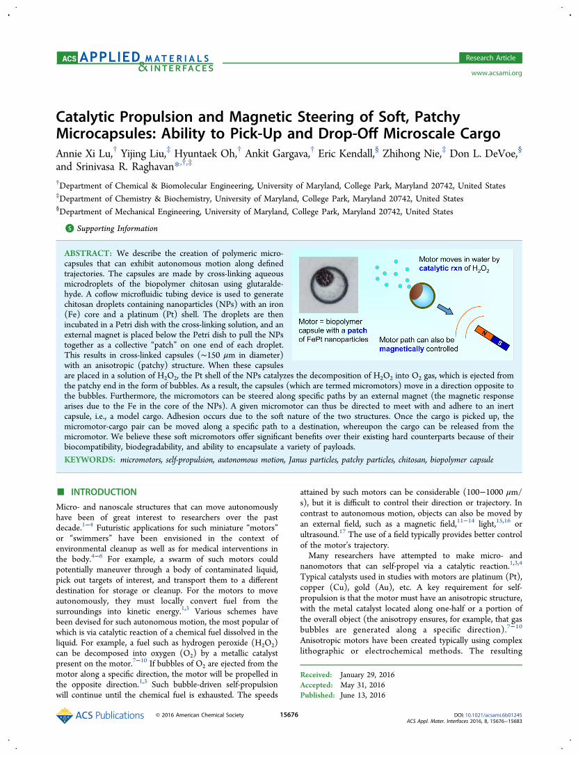
ABSTRACT: We describe the creation of polymeric micro-capsules that can exhibit autonomous motion along definedtrajectories. The capsules are made by cross-linking aqueousmicrodroplets of the biopolymer chitosan using glutaralde-hyde. A coflow microfluidic tubing device is used to generatechitosan droplets containing nanoparticles (NPs) with an iron(Fe) core and a platinum (Pt) shell. The droplets are thenincubated in a Petri dish with the cross-linking solution, and anexternal magnet is placed below the Petri dish to pull the NPstogether as a collective “patch” on one end of each droplet.This results in cross-linked capsules (∼150 μm in diameter)with an anisotropic (patchy) structure. When these capsulesare placed in a solution of H2O2, the Pt shell of the NPs catalyzes the decomposition of H2O2 into O2 gas, which is ejected fromthe patchy end in the form of bubbles. As a result, the capsules (which are termed micromotors) move in a direction opposite tothe bubbles. Furthermore, the micromotors can be steered along specific paths by an external magnet (the magnetic responsearises due to the Fe in the core of the NPs). A given micromotor can thus be directed to meet with and adhere to an inertcapsule, i.e., a model cargo. Adhesion occurs due to the soft nature of the two structures. Once the cargo is picked up, themicromotor-cargo pair can be moved along a specific path to a destination, whereupon the cargo can be released from themicromotor. We believe these soft micromotors offer significant benefits over their existing hard counterparts because of theirbiocompatibility, biodegradability, and ability to encapsulate a variety of payloads.
KEYWORDS: micromotors, self-propulsion, autonomous motion, Janus particles, patchy particles, chitosan, biopolymer capsule
■ INTRODUCTION
Micro- and nanoscale structures that can move autonomouslyhave been of great interest to researchers over the pastdecade.1−4 Futuristic applications for such miniature “motors”or “swimmers” have been envisioned in the context ofenvironmental cleanup as well as for medical interventions inthe body.4−6 For example, a swarm of such motors couldpotentially maneuver through a body of contaminated liquid,pick out targets of interest, and transport them to a differentdestination for storage or cleanup. For the motors to moveautonomously, they must locally convert fuel from thesurroundings into kinetic energy.1,3 Various schemes havebeen devised for such autonomous motion, the most popular ofwhich is via catalytic reaction of a chemical fuel dissolved in theliquid. For example, a fuel such as hydrogen peroxide (H2O2)can be decomposed into oxygen (O2) by a metallic catalystpresent on the motor.7−10 If bubbles of O2 are ejected from themotor along a specific direction, the motor will be propelled inthe opposite direction.1,3 Such bubble-driven self-propulsionwill continue until the chemical fuel is exhausted. The speeds
attained by such motors can be considerable (100−1000 μm/s), but it is difficult to control their direction or trajectory. Incontrast to autonomous motion, objects can also be moved byan external field, such as a magnetic field,11−14 light,15,16 orultrasound.17 The use of a field typically provides better controlof the motor’s trajectory.Many researchers have attempted to make micro- and
nanomotors that can self-propel via a catalytic reaction.1,3,4
Typical catalysts used in studies with motors are platinum (Pt),copper (Cu), gold (Au), etc. A key requirement for self-propulsion is that the motor must have an anisotropic structure,with the metal catalyst located along one-half or a portion ofthe overall object (the anisotropy ensures, for example, that gasbubbles are generated along a specific direction).7−10
Anisotropic motors have been created typically using complexlithographic or electrochemical methods. The resulting
Received: January 29, 2016Accepted: May 31, 2016Published: June 13, 2016
Research Article
www.acsami.org
© 2016 American Chemical Society 15676 DOI: 10.1021/acsami.6b01245ACS Appl. Mater. Interfaces 2016, 8, 15676−15683
structures include rods, tubes, or spheres with two or moredistinct portions, of which one portion is the catalyst (Pt or Au)while the remaining portions could be inert metals or inorganicsolids like silica. Note that, because such motors are solid, hardparticles, they are not likely to undergo biodegradation inaqueous environments. As an alternative, there have beenrecent attempts to design motors using soft materials such assynthetic polymers, biopolymers, or plant tissue.18−25 However,the materials and procedures used to produce polymericmotors are still relatively complex and labor-intensive (e.g.,layer-by-layer assembly in sacrificial porous templates21), andthereby not easy to replicate in typical laboratories. The presentstudy is motivated by the need for a simple, alternative strategyto fabricate soft, biodegradable motors out of commerciallyavailable materials. Ideally, these micromotors should have thesame functionalities as earlier motors, while possibly alsooffering additional capabilities.
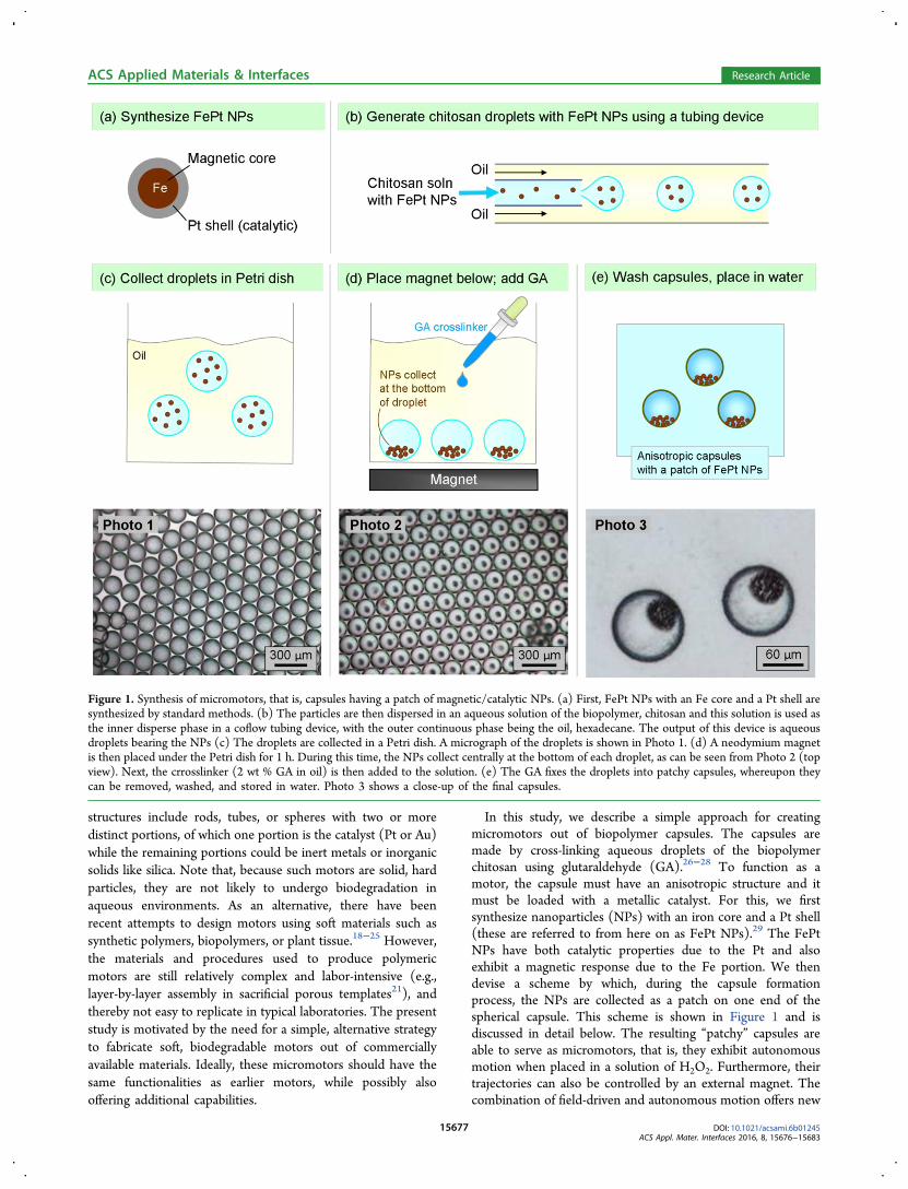
In this study, we describe a simple approach for creatingmicromotors out of biopolymer capsules. The capsules aremade by cross-linking aqueous droplets of the biopolymerchitosan using glutaraldehyde (GA).26−28 To function as amotor, the capsule must have an anisotropic structure and itmust be loaded with a metallic catalyst. For this, we firstsynthesize nanoparticles (NPs) with an iron core and a Pt shell(these are referred to from here on as FePt NPs).29 The FePtNPs have both catalytic properties due to the Pt and alsoexhibit a magnetic response due to the Fe portion. We thendevise a scheme by which, during the capsule formationprocess, the NPs are collected as a patch on one end of thespherical capsule. This scheme is shown in Figure 1 and isdiscussed in detail below. The resulting “patchy” capsules areable to serve as micromotors, that is, they exhibit autonomousmotion when placed in a solution of H2O2. Furthermore, theirtrajectories can also be controlled by an external magnet. Thecombination of field-driven and autonomous motion offers new
Figure 1. Synthesis of micromotors, that is, capsules having a patch of magnetic/catalytic NPs. (a) First, FePt NPs with an Fe core and a Pt shell aresynthesized by standard methods. (b) The particles are then dispersed in an aqueous solution of the biopolymer, chitosan and this solution is used asthe inner disperse phase in a coflow tubing device, with the outer continuous phase being the oil, hexadecane. The output of this device is aqueousdroplets bearing the NPs (c) The droplets are collected in a Petri dish. A micrograph of the droplets is shown in Photo 1. (d) A neodymium magnetis then placed under the Petri dish for 1 h. During this time, the NPs collect centrally at the bottom of each droplet, as can be seen from Photo 2 (topview). Next, the crrosslinker (2 wt % GA in oil) is then added to the solution. (e) The GA fixes the droplets into patchy capsules, whereupon theycan be removed, washed, and stored in water. Photo 3 shows a close-up of the final capsules.
ACS Applied Materials & Interfaces Research Article
DOI: 10.1021/acsami.6b01245ACS Appl. Mater. Interfaces 2016, 8, 15676−15683
15677
capabilities. We show that a given micromotor can be directedto pick up an inert microcapsule, move it to a different location,and release it at that location. This capability is made possiblebecause the micromotor is a soft structure that can physicallyadhere to other soft structures. In addition to the motivecapabilities, another attractive feature of our micromotorcapsule is that it can store payloads inside its core. Forexample, the capsule could be used to store chemicals that fighttoxins, or drugs that fight diseases.30 Thus, on the whole, webelieve these soft micromotors offer significant benefits overtheir existing hard counterparts.
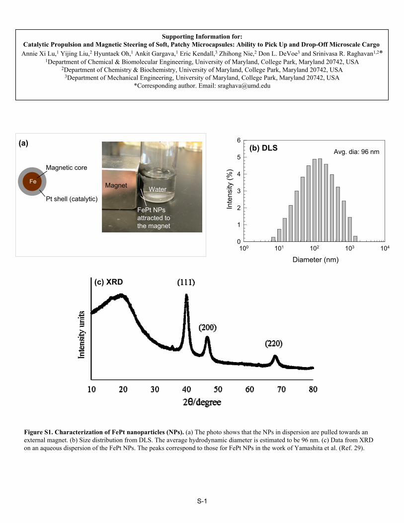
■ RESULTS AND DISCUSSIONOur procedure for fabricating capsules containing a patch ofFePt NPs is shown schematically in Figure 1. We firstsynthesized the FePt NPs, which have both magnetic andcatalytic capabilities from their Fe core and Pt shell,respectively. The procedure (detailed in the Materials andMethods section) involves the thermal decomposition of ironpentacarbonyl (Fe(CO)5) and subsequent reduction ofplatinum acetylacetonate in the presence of oleic acid andoleyl-amine.29 The average diameter of the NPs was measuredto be 96 nm by dynamic light scattering (DLS) and thestructure was verified by X-ray diffraction (XRD) (see FigureS1). In addition to being magnetic and catalytic, the core/shellstructure of the NPs provides the benefit of reduced materialcost as opposed to using pure Pt NPs.We then used a capillary coflow device to make droplets of
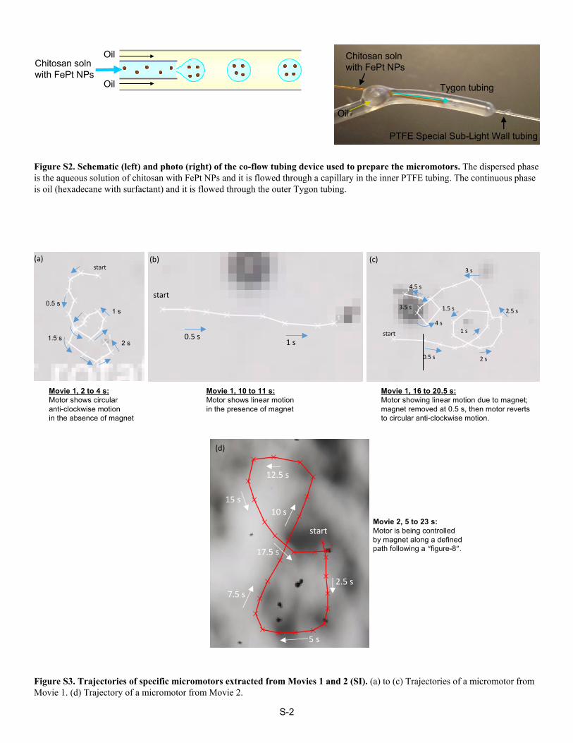
the biopolymer, chitosan bearing FePt NPs (Figure 1b) (photoprovided in Figure S2). First, 0.01 wt % FePt NPs weredispersed in a 2 wt % chitosan solution. This aqueous solutionserved as the dispersed phase, and it was sent through the innercapillary. The oil phase was hexadecane containing the nonionicsurfactant, Span 80 (2 wt %) and it was injected through theouter tubing as the continuous phase. Both flow rates werecontrolled by syringe pumps, with typical values of 10 μL/min(outer) and 1 μL/min (inner). The droplets generated by thetubing device were then collected in a plastic Petri dish (Figure1c). Photo 1 shows that the droplets were nearly monodisperse,with a diameter ∼150 μm. Next, the Petri dish was placed ontop of a neodymium magnet (Figure 1d). Within 1 h, all of theFePt NPs were concentrated as a dense patch at the bottom ofeach droplet (i.e., the side closest to the magnet). Photo 2,which is a top view, confirms this localization of the NPs, andwe note that the droplets form an ordered array at this stage.Next, a solution of 2 wt % GA in hexadecane was added
dropwise to the Petri dish (Figure 1d). GA is a dialdehyde thatforms covalent cross-links between chitosan chains. Thus, GA-induced cross-linking converted the liquid droplets into solidcapsules with a patch of NPs. Within 10 min of GA addition,the patch was fixed; thereafter, the NPs remained localized intheir patch even if the magnet was removed. The capsules wereleft overnight in the Petri dish, during which time, the cross-linking continued and the capsules hardened. Then the capsuleswere washed with decanol and ethanol and redispersed inwater. The washed capsules were then filtered using 160 μmNylon filters to remove any coalesced structures. The finalpatchy capsules are relatively monodisperse and discrete(Figure 1e). Their average diameter is ∼100 μm, which isabout 30% smaller than the diameter of the original droplets(such decrease in size is typical of GA cross-linking18,19). Photo3 shows a close-up of individual capsules, and it clearly reveals apatch of 15−30 μm in diameter on one end of each capsule
where all the NPs are collected. We will refer to these patchycapsules from here on as “micromotors”. The above method forpreparing patchy capsules is similar to that in recent reports(where the focus was on generating patchy magneticparticles);31,32 to our knowledge, this is the first time thismethod has been coupled with catalytic NPs to producemicromotors.To study the self-propulsion of the micromotors, we placed
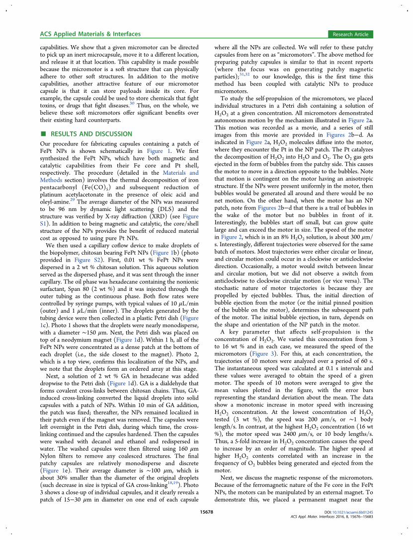
individual structures in a Petri dish containing a solution ofH2O2 at a given concentration. All micromotors demonstratedautonomous motion by the mechanism illustrated in Figure 2a.This motion was recorded as a movie, and a series of stillimages from this movie are provided in Figures 2b−d. Asindicated in Figure 2a, H2O2 molecules diffuse into the motor,where they encounter the Pt in the NP patch. The Pt catalyzesthe decomposition of H2O2 into H2O and O2. The O2 gas getsejected in the form of bubbles from the patchy side. This causesthe motor to move in a direction opposite to the bubbles. Notethat motion is contingent on the motor having an anisotropicstructure. If the NPs were present uniformly in the motor, thenbubbles would be generated all around and there would be nonet motion. On the other hand, when the motor has an NPpatch, note from Figures 2b−d that there is a trail of bubbles inthe wake of the motor but no bubbles in front of it.Interestingly, the bubbles start off small, but can grow quitelarge and can exceed the motor in size. The speed of the motorin Figure 2, which is in an 8% H2O2 solution, is about 300 μm/s. Interestingly, different trajectories were observed for the samebatch of motors. Most trajectories were either circular or linear,and circular motion could occur in a clockwise or anticlockwisedirection. Occasionally, a motor would switch between linearand circular motion, but we did not observe a switch fromanticlockwise to clockwise circular motion (or vice versa). Thestochastic nature of motor trajectories is because they arepropelled by ejected bubbles. Thus, the initial direction ofbubble ejection from the motor (or the initial pinned positionof the bubble on the motor), determines the subsequent pathof the motor. The initial bubble ejection, in turn, depends onthe shape and orientation of the NP patch in the motor.A key parameter that affects self-propulsion is the
concentration of H2O2. We varied this concentration from 3to 16 wt % and in each case, we measured the speed of themicromotors (Figure 3). For this, at each concentration, thetrajectories of 10 motors were analyzed over a period of 60 s.The instantaneous speed was calculated at 0.1 s intervals andthese values were averaged to obtain the speed of a givenmotor. The speeds of 10 motors were averaged to give themean values plotted in the figure, with the error barsrepresenting the standard deviation about the mean. The datashow a monotonic increase in motor speed with increasingH2O2 concentration. At the lowest concentration of H2O2tested (3 wt %), the speed was 200 μm/s, or ∼1 bodylength/s. In contrast, at the highest H2O2 concentration (16 wt%), the motor speed was 2400 μm/s, or 10 body lengths/s.Thus, a 5-fold increase in H2O2 concentration causes the speedto increase by an order of magnitude. The higher speed athigher H2O2 contents correlated with an increase in thefrequency of O2 bubbles being generated and ejected from themotor.Next, we discuss the magnetic response of the micromotors.
Because of the ferromagnetic nature of the Fe core in the FePtNPs, the motors can be manipulated by an external magnet. Todemonstrate this, we placed a permanent magnet near the
ACS Applied Materials & Interfaces Research Article
DOI: 10.1021/acsami.6b01245ACS Appl. Mater. Interfaces 2016, 8, 15676−15683
15678
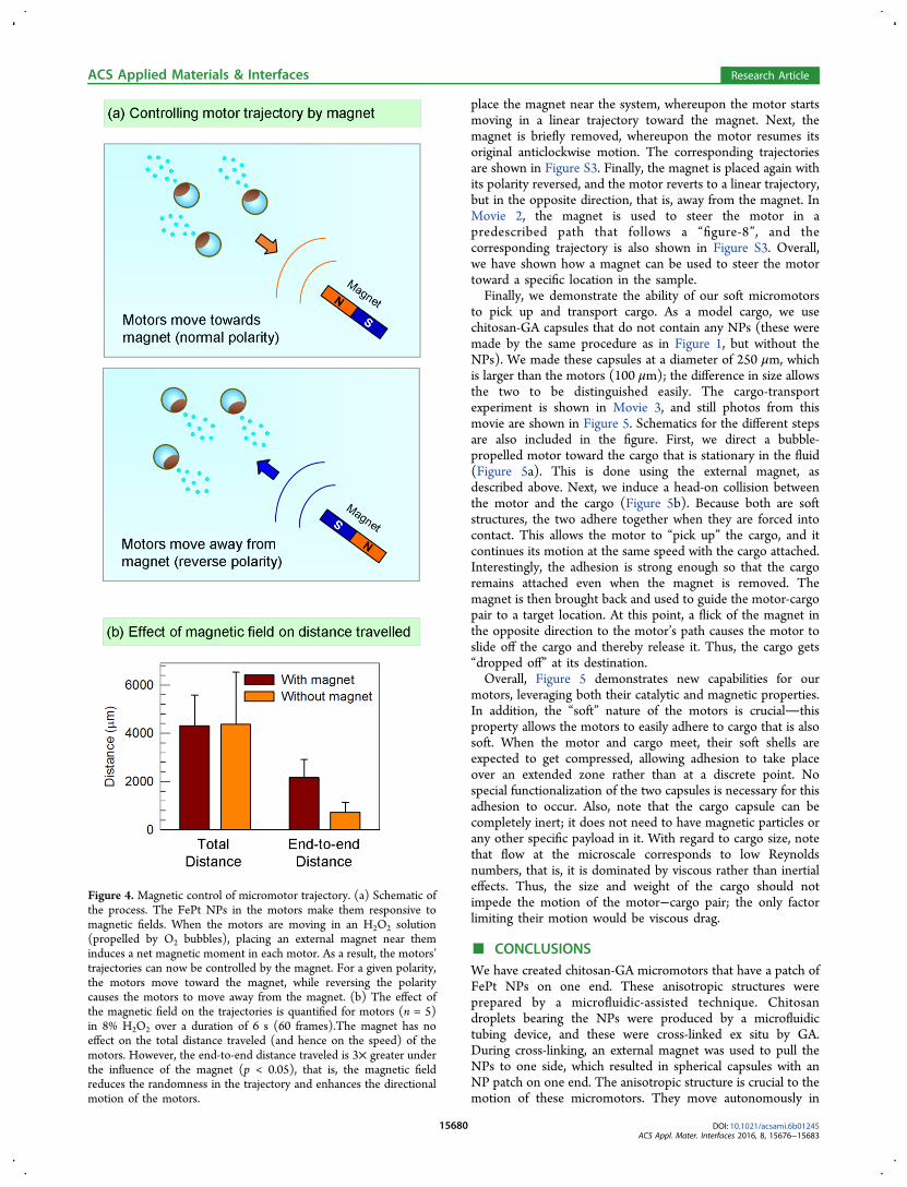
motors as they were moving randomly in an 8% H2O2 solution.This scenario is shown schematically in Figure 4a. The magnetwas a powerful neodymium piece (1 in. cube) with a surfacefield strength of 0.57 T and it was placed 1−2 in. away from themotors (which were in a Petri dish containing the solution). On
the basis of the magnet size and position relative to the motors,we expect the motors to be exposed to a constant magneticfield. For a given orientation (i.e., polarity) of the magnet, themotors move in unison toward the magnet. When the polarityof the magnet is reversed, the motors collectively move awayfrom the magnet. This indicates that the motors havemagnetization with defined polarity, allowing them to self-align relative to the applied magnetic field and move in adirection opposite to the magnetic field vector.13 Wehypothesize that the polarity is induced during capsulesynthesis (Figure 1), that is, the neodymium magnet orientsthe magnetic domains of the FePt NPs in the patch within thecapsule. This ensures that the magnetic moments fromneighboring NPs add up rather than cancel each other.We then attempted to clarify the effect of the magnet on
micromotor propulsion. Does the magnet affect both thedirection and the speed of the motors? For this, we studiedseveral (n = 5) motors in 8% H2O2 and recorded theirtrajectories for two cases: first, when they were propelled bybubble ejection alone, and then when they were also under theinfluence of an external magnet. For the two cases, wecomputed the total distance traveled over 6 s by adding up thedistances (step sizes) traversed every 0.1 s. In addition, we alsocalculated the end-to-end distance, that is, the net distancetraveled by each motor from its initial origin to its finaldestination. The results are averaged and shown in Figure 4b.We note that the total distance traveled is virtually identicalwith and without the magnet. This means that the magnet hasno influence on the speed of the motors. In other words, thepropulsion of the motors is due to the bubbles alone and notdue to the magnetic field. This is why the motors always movein a direction opposite to the bubbles. Also, if there is no H2O2in the solution, the magnet alone cannot propel the motor. Theutility of the magnet is in steering, that is, in providingdirectionality to the self-propelling motors. In the absence ofthe magnet, the motors move in random, irregular paths.However, if a magnet is present, the motors move in a specificdirection. This is why the end-to-end distance in Figure 4b is 3times higher (p < 0.05) with the magnet than without. Similarobservations have been made in previous studies.Magnetic steering of micromotors is further demonstrated by
Movies 1 and 2). In Movie 1, we focus on a motor that ismoving anticlockwise in the absence of a magnet. Then, we
Figure 2. Self-propulsion of micromotors in H2O2 solution. (a)Schematic of the propulsion mechanism. The motor has a patch ofFePt NPs. The Pt in the NPs catalyzes the decomposition of H2O2 togenerate O2 gas in the form of bubbles. The bubbles are ejected fromthe side with the NP patch, which propels the motor in the oppositedirection. (b−d) Still photos from a movie demonstrating thepropulsion of the motor. The reference bubble on the right side ofthe photos provides a convenient way to visualize how far the motorhas traveled in a given length of time. Note that the motor movesopposite to the direction in which the bubbles are ejected. The scalebar in each image represents 300 μm.
Figure 3. Effect of H2O2 concentration on micromotor speed. At eachconcentration, the trajectories of 10 motors were sampled over aperiod of 60 s, and the mean speeds were thereby computed and areshown. Error bars represent standard deviations about the mean.
ACS Applied Materials & Interfaces Research Article
DOI: 10.1021/acsami.6b01245ACS Appl. Mater. Interfaces 2016, 8, 15676−15683
15679
place the magnet near the system, whereupon the motor startsmoving in a linear trajectory toward the magnet. Next, themagnet is briefly removed, whereupon the motor resumes itsoriginal anticlockwise motion. The corresponding trajectoriesare shown in Figure S3. Finally, the magnet is placed again withits polarity reversed, and the motor reverts to a linear trajectory,but in the opposite direction, that is, away from the magnet. InMovie 2, the magnet is used to steer the motor in apredescribed path that follows a “figure-8”, and thecorresponding trajectory is also shown in Figure S3. Overall,we have shown how a magnet can be used to steer the motortoward a specific location in the sample.Finally, we demonstrate the ability of our soft micromotors
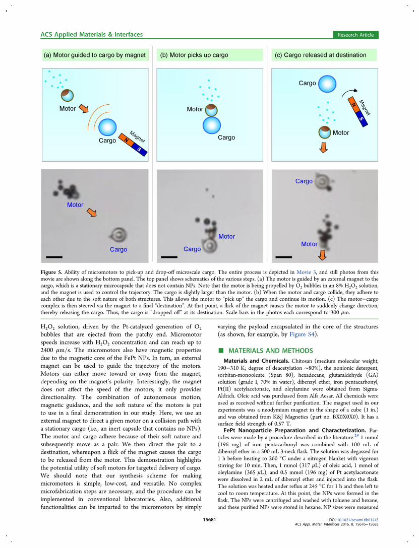
to pick up and transport cargo. As a model cargo, we usechitosan-GA capsules that do not contain any NPs (these weremade by the same procedure as in Figure 1, but without theNPs). We made these capsules at a diameter of 250 μm, whichis larger than the motors (100 μm); the difference in size allowsthe two to be distinguished easily. The cargo-transportexperiment is shown in Movie 3, and still photos from thismovie are shown in Figure 5. Schematics for the different stepsare also included in the figure. First, we direct a bubble-propelled motor toward the cargo that is stationary in the fluid(Figure 5a). This is done using the external magnet, asdescribed above. Next, we induce a head-on collision betweenthe motor and the cargo (Figure 5b). Because both are softstructures, the two adhere together when they are forced intocontact. This allows the motor to “pick up” the cargo, and itcontinues its motion at the same speed with the cargo attached.Interestingly, the adhesion is strong enough so that the cargoremains attached even when the magnet is removed. Themagnet is then brought back and used to guide the motor-cargopair to a target location. At this point, a flick of the magnet inthe opposite direction to the motor’s path causes the motor toslide off the cargo and thereby release it. Thus, the cargo gets“dropped off” at its destination.Overall, Figure 5 demonstrates new capabilities for our
motors, leveraging both their catalytic and magnetic properties.In addition, the “soft” nature of the motors is crucialthisproperty allows the motors to easily adhere to cargo that is alsosoft. When the motor and cargo meet, their soft shells areexpected to get compressed, allowing adhesion to take placeover an extended zone rather than at a discrete point. Nospecial functionalization of the two capsules is necessary for thisadhesion to occur. Also, note that the cargo capsule can becompletely inert; it does not need to have magnetic particles orany other specific payload in it. With regard to cargo size, notethat flow at the microscale corresponds to low Reynoldsnumbers, that is, it is dominated by viscous rather than inertialeffects. Thus, the size and weight of the cargo should notimpede the motion of the motor−cargo pair; the only factorlimiting their motion would be viscous drag.
■ CONCLUSIONSWe have created chitosan-GA micromotors that have a patch ofFePt NPs on one end. These anisotropic structures wereprepared by a microfluidic-assisted technique. Chitosandroplets bearing the NPs were produced by a microfluidictubing device, and these were cross-linked ex situ by GA.During cross-linking, an external magnet was used to pull theNPs to one side, which resulted in spherical capsules with anNP patch on one end. The anisotropic structure is crucial to themotion of these micromotors. They move autonomously in
Figure 4. Magnetic control of micromotor trajectory. (a) Schematic ofthe process. The FePt NPs in the motors make them responsive tomagnetic fields. When the motors are moving in an H2O2 solution(propelled by O2 bubbles), placing an external magnet near theminduces a net magnetic moment in each motor. As a result, the motors’trajectories can now be controlled by the magnet. For a given polarity,the motors move toward the magnet, while reversing the polaritycauses the motors to move away from the magnet. (b) The effect ofthe magnetic field on the trajectories is quantified for motors (n = 5)in 8% H2O2 over a duration of 6 s (60 frames).The magnet has noeffect on the total distance traveled (and hence on the speed) of themotors. However, the end-to-end distance traveled is 3× greater underthe influence of the magnet (p < 0.05), that is, the magnetic fieldreduces the randomness in the trajectory and enhances the directionalmotion of the motors.
ACS Applied Materials & Interfaces Research Article
DOI: 10.1021/acsami.6b01245ACS Appl. Mater. Interfaces 2016, 8, 15676−15683
15680
H2O2 solution, driven by the Pt-catalyzed generation of O2
bubbles that are ejected from the patchy end. Micromotorspeeds increase with H2O2 concentration and can reach up to2400 μm/s. The micromotors also have magnetic propertiesdue to the magnetic core of the FePt NPs. In turn, an externalmagnet can be used to guide the trajectory of the motors.Motors can either move toward or away from the magnet,depending on the magnet’s polarity. Interestingly, the magnetdoes not affect the speed of the motors; it only providesdirectionality. The combination of autonomous motion,magnetic guidance, and the soft nature of the motors is putto use in a final demonstration in our study. Here, we use anexternal magnet to direct a given motor on a collision path witha stationary cargo (i.e., an inert capsule that contains no NPs).The motor and cargo adhere because of their soft nature andsubsequently move as a pair. We then direct the pair to adestination, whereupon a flick of the magnet causes the cargoto be released from the motor. This demonstration highlightsthe potential utility of soft motors for targeted delivery of cargo.We should note that our synthesis scheme for makingmicromotors is simple, low-cost, and versatile. No complexmicrofabrication steps are necessary, and the procedure can beimplemented in conventional laboratories. Also, additionalfunctionalities can be imparted to the micromotors by simply
varying the payload encapsulated in the core of the structures(as shown, for example, by Figure S4).
■ MATERIALS AND METHODSMaterials and Chemicals. Chitosan (medium molecular weight,
190−310 K; degree of deacetylation ∼80%), the nonionic detergent,sorbitan-monooleate (Span 80), hexadecane, glutaraldehyde (GA)solution (grade I, 70% in water), dibenzyl ether, iron pentacarbonyl,Pt(II) acetylacetonate, and oleylamine were obtained from Sigma-Aldrich. Oleic acid was purchased from Alfa Aesar. All chemicals wereused as received without further purification. The magnet used in ourexperiments was a neodymium magnet in the shape of a cube (1 in.)and was obtained from K&J Magnetics (part no. BX0X0X0). It has asurface field strength of 0.57 T.
FePt Nanoparticle Preparation and Characterization. Par-ticles were made by a procedure described in the literature.29 1 mmol(196 mg) of iron pentacarbonyl was combined with 100 mL ofdibenzyl ether in a 500 mL 3-neck flask. The solution was degassed for1 h before heating to 260 °C under a nitrogen blanket with vigorousstirring for 10 min. Then, 1 mmol (317 μL) of oleic acid, 1 mmol ofoleylamine (365 μL), and 0.5 mmol (196 mg) of Pt acetylacetonatewere dissolved in 2 mL of dibenzyl ether and injected into the flask.The solution was heated under reflux at 245 °C for 1 h and then left tocool to room temperature. At this point, the NPs were formed in theflask. The NPs were centrifuged and washed with toluene and hexane,and these purified NPs were stored in hexane. NP sizes were measured
Figure 5. Ability of micromotors to pick-up and drop-off microscale cargo. The entire process is depicted in Movie 3, and still photos from thismovie are shown along the bottom panel. The top panel shows schematics of the various steps. (a) The motor is guided by an external magnet to thecargo, which is a stationary microcapsule that does not contain NPs. Note that the motor is being propelled by O2 bubbles in an 8% H2O2 solution,and the magnet is used to control the trajectory. The cargo is slightly larger than the motor. (b) When the motor and cargo collide, they adhere toeach other due to the soft nature of both structures. This allows the motor to “pick up” the cargo and continue its motion. (c) The motor−cargocomplex is then steered via the magnet to a final “destination”. At that point, a flick of the magnet causes the motor to suddenly change direction,thereby releasing the cargo. Thus, the cargo is “dropped off” at its destination. Scale bars in the photos each correspond to 300 μm.
ACS Applied Materials & Interfaces Research Article
DOI: 10.1021/acsami.6b01245ACS Appl. Mater. Interfaces 2016, 8, 15676−15683
15681
by dynamic light scattering on a Photocor-FC instrument (5 mW laserat 633 nm, 90° scattering angle, logarithmic correlator).Solution Preparation. For preparing capsules using the micro-
fluidic tubing device, several different solutions were first prepared.First, 2 wt % chitosan was dissolved in a 0.2 M acetic acid solution.Next, approximately 10 mL of FePt/hexane solution was vacuum-driedovernight, which yielded 0.003 g of dry FePt NPs. To the dry NPs, 5 gof 2 wt % chitosan was added, and the mixture was vortexed andsonicated for 30 min before use. This mixture serves as the aqueousdispersed phase. The oily continuous phase was prepared by dissolving2 wt % of Span 80 in hexadecane. Finally, the incubation phase was asolution in hexadecane containing 2 wt % of Span 80 and 2 wt % ofGA. This solution was vortexed and sonicated for 30 min before use.Microfluidic Tubing Device Fabrication. To prepare the coflow
tubing device (see photo in Figure S1a), capillary 1, a round glasscapillary (from Fiber Optics Center, Inc.) with a 50 μm inner diameter(ID), 80 μm outer diameter (OD) was inserted into capillary 2, a glasscapillary (Polymicro Technologies) with a 100 μm ID, 360 μm OD,and sealed with epoxy. The glued set of capillaries was then threadedinto Tygon tubing (Cole-Palmer) with a 1/32 in. ID × 1/16 in. ODthrough an extruded hole in the middle of the tubing. The tip ofcapillary 1 was slightly recessed within the Tygon tubing. A PTFEspecial sub-light wall tubing with 0.004 in. I.D. was then threaded ontothe tip of capillary 1 and also encased within the main PTFE tubing.Finally, all the openings were sealed with epoxy, with the end ofcapillary 2 connected to a syringe filled with the aqueous continuousphase, and the end of the Tygon tubing connected to a syringe withthe oily dispersed phase.Patchy Capsule Preparation. Capsules were prepared by
generating aqueous droplets through the coflow tubing device andcross-linking these droplets by GA. The flow rate of the aqueousdispersed phase was 1 μL/min whereas the oily continuous was flowedat 10 μL/min. The droplets generated at the output of the tubingdevice were collected in a plastic Petri dish containing the continuousphase (Figure 1). After collection, the Petri dish was carefully placedon top of the neodymium magnet for 1 h until all of the FePt NPswere concentrated to a point at the bottom of each aqueous droplet.Then, the incubation phase with GA was carefully added to the Petridish. After about 10 min, the anisotropy was fixed and the Petri dishcould be removed from the magnet and allowed to further cross-linkovernight. The cross-linked capsules were then purified by purgingwith nitrogen gas overnight, followed by washing with decanol andethanol. The purified capsules were finally resuspended in deionizedwater.Image Analysis. Bright-field optical images and movies of the
capsules and motors were taken with a Nikon Eclipse LV-100Profilometer Microscope. Capsule sizes (length and radius) weredetermined using the Nikon Microscope software. Mean speed anddistance traveled were analyzed using ImageJ’s MTrackJ plug-in,averaged over at least 10 s of recorded video.
■ ASSOCIATED CONTENT
*S Supporting InformationThe Supporting Information is available free of charge on theACS Publications website at DOI: 10.1021/acsami.6b01245.
Additional characterization of the nanoparticles, a photoof the coflow tubing device, and trajectories of themicromotors (PDF)Movie showing control of motor trajectory by a magnet(MPG)Movie of a magnet-guided motor being moved in a figure8 path (MPG)Movie of a micromotor picking up and dropping offmicroscale cargo (MPG)
■ AUTHOR INFORMATION
Corresponding Author*E-mail: [email protected].
NotesThe authors declare no competing financial interest.
■ ACKNOWLEDGMENTS
This work was partially funded by a grant from NSF. AXL wassupported by a SMART scholarship from the Department ofDefense.
■ REFERENCES(1) Wang, W.; Duan, W. T.; Ahmed, S.; Mallouk, T. E.; Sen, A. SmallPower: Autonomous Nano- And Micromotors Propelled By Self-Generated Gradients. Nano Today 2013, 8, 531−554.(2) Guix, M.; Mayorga-Martinez, C. C.; Merkoci, A. Nano/Micromotors in (Bio)chemical Science Applications. Chem. Rev.2014, 114, 6285−6322.(3) Ebbens, S. J.; Howse, J. R. In Pursuit of Propulsion at theNanoscale. Soft Matter 2010, 6, 726−738.(4) Gao, W.; Wang, J. The Environmental Impact of Micro/Nanomachines. A Review. ACS Nano 2014, 8, 3170−3180.(5) Orozco, J.; Campuzano, S.; Kagan, D.; Zhou, M.; Gao, W.; Wang,J. Dynamic Isolation and Unloading of Target Proteins by Aptamer-Modified Microtransporters. Anal. Chem. 2011, 83, 7962−7969.(6) Guix, M.; Orozco, J.; Garcia, M.; Gao, W.; Sattayasamitsathit, S.;Merkoci, A.; Escarpa, A.; Wang, J. Superhydrophobic Alkanethiol-Coated Microsubmarines for Effective Removal of Oil. ACS Nano2012, 6, 4445−4451.(7) Ismagilov, R. F.; Schwartz, A.; Bowden, N.; Whitesides, G. M.Autonomous Movement and Self-Assembly. Angew. Chem., Int. Ed.2002, 41, 652−655.(8) Paxton, W. F.; Kistler, K. C.; Olmeda, C. C.; Sen, A.; St. Angelo,S. K.; Cao, Y. Y.; Mallouk, T. E.; Lammert, P. E.; Crespi, V. H.Catalytic nanomotors: Autonomous Movement of Striped Nanorods.J. Am. Chem. Soc. 2004, 126, 13424−13431.(9) Wheat, P. M.; Marine, N. A.; Moran, J. L.; Posner, J. D. RapidFabrication of Bimetallic Spherical Motors. Langmuir 2010, 26,13052−13055.(10) Baraban, L.; Tasinkevych, M.; Popescu, M. N.; Sanchez, S.;Dietrich, S.; Schmidt, O. G. Transport of Cargo by Catalytic JanusMicro-motors. Soft Matter 2012, 8, 48−52.(11) Burdick, J.; Laocharoensuk, R.; Wheat, P. M.; Posner, J. D.;Wang, J. Synthetic Nanomotors in Microchannel Networks: Direc-tional Microchip Motion and Controlled Manipulation of Cargo. J.Am. Chem. Soc. 2008, 130, 8164−8168.(12) Solovev, A. A.; Sanchez, S.; Pumera, M.; Mei, Y. F.; Schmidt, O.G. Magnetic Control of Tubular Catalytic Microbots for theTransport, Assembly, and Delivery of Micro-objects. Adv. Funct.Mater. 2010, 20, 2430−2435.(13) Zhao, G. J.; Sanchez, S.; Schmidt, O. G.; Pumera, M.Micromotors with Built-in Compasses. Chem. Commun. 2012, 48,10090−10092.(14) Singh, A. K.; Dey, K. K.; Chattopadhyay, A.; Mandal, T. K.;Bandyopadhyay, D. Multimodal Chemo-Magnetic Control of Self-Propelling Microbots. Nanoscale 2014, 6, 1398−1405.(15) Jiang, H. R.; Yoshinaga, N.; Sano, M. Active Motion of a JanusParticle by Self-Thermophoresis in a Defocused Laser Beam. Phys. Rev.Lett. 2010, 105, 105.(16) Palacci, J.; Sacanna, S.; Vatchinsky, A.; Chaikin, P. M.; Pine, D. J.Photoactivated Colloidal Dockers for Cargo Transportation. J. Am.Chem. Soc. 2013, 135, 15978−15981.(17) Rao, K. J.; Li, F.; Meng, L.; Zheng, H. R.; Cai, F. Y.; Wang, W. AForce to be Reckoned With: A Review of Synthetic MicroswimmersPowered by Ultrasound. Small 2015, 11, 2836−2846.
ACS Applied Materials & Interfaces Research Article
DOI: 10.1021/acsami.6b01245ACS Appl. Mater. Interfaces 2016, 8, 15676−15683
15682
(18) Wu, Y. J.; Wu, Z. G.; Lin, X. K.; He, Q.; Li, J. B. AutonomousMovement of Controllable Assembled Janus Capsule Motors. ACSNano 2012, 6, 10910−10916.(19) Wilson, D. A.; Nolte, R. J. M.; van Hest, J. C. M. AutonomousMovement of Platinum-Loaded Stomatocytes. Nat. Chem. 2012, 4,268−274.(20) Gu, Y. G.; Sattayasamitsathit, S.; Kaufmann, K.; Vazquez-Duhalt,R.; Gao, W.; Wang, C. M.; Wang, J. Self-Propelled Chemically-Powered Plant-Tissue Biomotors. Chem. Commun. 2013, 49, 7307−7309.(21) Wu, Z. G.; Wu, Y. J.; He, W. P.; Lin, X. K.; Sun, J. M.; He, Q.Self-Propelled Polymer-Based Multilayer Nanorockets for Trans-portation and Drug Release. Angew. Chem., Int. Ed. 2013, 52, 7000−7003.(22) Wu, Y.; Lin, X.; Wu, Z.; Mohwald, H.; He, Q. Self-propelledPolymer Multilayer Janus Capsules for Effective Drug Delivery andLight-Triggered Release. ACS Appl. Mater. Interfaces 2014, 6, 10476−10481.(23) Wu, Z. G.; Lin, X. K.; Wu, Y. J.; Si, T. Y.; Sun, J. M.; He, Q.Near-Infrared Light-Triggered ″On/Off″ Motion of Polymer Multilayer Rockets. ACS Nano 2014, 8, 6097−6105.(24) Wu, Z. G.; Lin, X. K.; Zou, X.; Sun, J. M.; He, Q. BiodegradableProtein-Based Rockets for Drug Transportation and Light-TriggeredRelease. ACS Appl. Mater. Interfaces 2015, 7, 250−255.(25) Xuan, M. J.; Shao, J. X.; Lin, X. K.; Dai, L. R.; He, Q. Light-Activated Janus Self-Assembled Capsule Micromotors. Colloids Surf., A2015, 482, 92−97.(26) Jiang, K. Q.; Xue, C.; Arya, C. D.; Shao, C. R.; George, E. O.;DeVoe, D. L.; Raghavan, S. R. A New Approach to in-situ″Micromanufacturing″: Microfluidic Fabrication of Magnetic andFluorescent Chains Using Chitosan Microparticles as Building Blocks.Small 2011, 7, 2469−2476.(27) Arya, C.; Kralj, J. G.; Jiang, K. Q.; Munson, M. S.; Forbes, T. P.;DeVoe, D. L.; Raghavan, S. R.; Forry, S. P. Capturing Rare Cells fromBlood Using a Packed Bed of Custom-Synthesized ChitosanMicroparticles. J. Mater. Chem. B 2013, 1, 4313−4319.(28) Lu, A. X.; Jiang, K. Q.; DeVoe, D. L.; Raghavan, S. R.Microfluidic Assembly of Janus-Like Dimer Capsules. Langmuir 2013,29, 13624−13629.(29) Mori, K.; Yoshioka, N.; Kondo, Y.; Takeuchi, T.; Yamashita, H.Catalytically Active, Magnetically Separable, and Water-Soluble FePtNanoparticles Modified with Cyclodextrin for Aqueous Hydro-genation Reactions. Green Chem. 2009, 11, 1337.(30) Dowling, M. B.; Bagal, A. S.; Raghavan, S. R. Self-Destructing″Mothership″ Capsules for Timed Release of Encapsulated Contents.Langmuir 2013, 29, 7993−7998.(31) Dyab, A. K. F.; Ozmen, M.; Ersoz, M.; Paunov, V. N.Fabrication of Novel Anisotropic Magnetic Microparticles. J. Mater.Chem. 2009, 19, 3475.(32) Shang, L.; Shangguan, F.; Cheng, Y.; Lu, J.; Xie, Z.; Zhao, Y.;Gu, Z. Microfluidic Generation of Magnetoresponsive Janus PhotonicCrystal Particles. Nanoscale 2013, 5, 9553−9557.
ACS Applied Materials & Interfaces Research Article
DOI: 10.1021/acsami.6b01245ACS Appl. Mater. Interfaces 2016, 8, 15676−15683
15683
Supporting Information for:Catalytic Propulsion and Magnetic Steering of Soft, Patchy Microcapsules: Ability to Pick Up and Drop-Off Microscale Cargo
Annie Xi Lu,1 Yijing Liu,2 Hyuntaek Oh,1 Ankit Gargava,1 Eric Kendall,3 Zhihong Nie,2 Don L. DeVoe3 and Srinivasa R. Raghavan1,2*1Department of Chemical & Biomolecular Engineering, University of Maryland, College Park, Maryland 20742, USA
2Department of Chemistry & Biochemistry, University of Maryland, College Park, Maryland 20742, USA3Department of Mechanical Engineering, University of Maryland, College Park, Maryland 20742, USA
*Corresponding author. Email: [email protected]
Figure S1. Characterization of FePt nanoparticles (NPs). (a) The photo shows that the NPs in dispersion are pulled towards anexternal magnet. (b) Size distribution from DLS. The average hydrodynamic diameter is estimated to be 96 nm. (c) Data from XRD on an aqueous dispersion of the FePt NPs. The peaks correspond to those for FePt NPs in the work of Yamashita et al. (Ref. 29).
(c) XRD
Fe
Pt shell (catalytic)
Magnetic core
MagnetWater
FePt NPsattracted tothe magnet
(a)
Diameter (nm)
100 101 102 103 104
Inte
nsity
(%
)
0
1
2
3
4
5
6(b) DLS Avg. dia: 96 nm
S-1
Oil
Oil
Chitosan solnwith FePt NPs
PTFE Special Sub-Light Wall tubing
Tygon tubing
Chitosan solnwith FePt NPs
Oil
Figure S2. Schematic (left) and photo (right) of the co-flow tubing device used to prepare the micromotors. The dispersed phase is the aqueous solution of chitosan with FePt NPs and it is flowed through a capillary in the inner PTFE tubing. The continuous phase is oil (hexadecane with surfactant) and it is flowed through the outer Tygon tubing.
Figure S3. Trajectories of specific micromotors extracted from Movies 1 and 2 (SI). (a) to (c) Trajectories of a micromotor from Movie 1. (d) Trajectory of a micromotor from Movie 2.
start
2.5 s
5 s
7.5 s
10 s
12.5 s
15 s
17.5 s
Movie 2, 5 to 23 s:Motor is being controlledby magnet along a definedpath following a “figure-8”.
(d)
Movie 1, 2 to 4 s:Motor shows circularanti-clockwise motionin the absence of magnet
Movie 1, 10 to 11 s:Motor shows linear motionin the presence of magnet
Movie 1, 16 to 20.5 s:Motor showing linear motion due to magnet; magnet removed at 0.5 s, then motor reverts to circular anti-clockwise motion.
start
0.5 s1 s
1.5 s2 s
(a)
start
0.5 s1 s
(b)
4 s
start
0.5 s
1 s
1.5 s
2 s
2.5 s
3 s
3.5 s
4.5 s
(c)
S-2
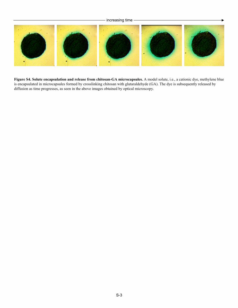
Figure S4. Solute encapsulation and release from chitosan-GA microcapsules. A model solute, i.e., a cationic dye, methylene blue is encapsulated in microcapsules formed by crosslinking chitosan with glutaraldehyde (GA). The dye is subsequently released by diffusion as time progresses, as seen in the above images obtained by optical microscopy.
increasing time
S-3