Catalyst 6500 DFC4 Installation Note - · PDF fileCatalyst 6500 Series Distributed Forwarding...
36
Americas Headquarters: Cisco Systems, Inc., 170 West Tasman Drive, San Jose, CA 95134-1706 USA Catalyst 6500 Series Distributed Forwarding Card 4 for WS-X68xx, WS-X69xx, and Select WS-X67xx Modules Installation Note Revised: January 2014 Product numbers: This publication contains the procedures for installing and removing the Distributed Forwarding Card 4 (DFC4) daughter card on the WS-X67xx Ethernet modules that support the DFC4. Note Throughout this publication, unless otherwise noted, the term DFC4 daughter card refers to the DFC4-A, DFC4-AXL, DFC4-E, and DFC4-EXL daughter cards. Contents This publication contains these sections: • Overview, page 2 • Required Tools and Parts, page 3 • Safety Overview, page 4 • Removing a CFC or DFC3 Daughter Card, page 10 • Removing a DFC4 Daughter Card, page 18 • Installing a DFC4 Daughter Card, page 23 WS-F6K-DFC4-A(=) WS-F6K-DFC4-AXL(=) WS-F6K-DFC4-E(=) WS-F6K-DFC4-EXL(=)
Transcript of Catalyst 6500 DFC4 Installation Note - · PDF fileCatalyst 6500 Series Distributed Forwarding...
Catalyst 6500 Series Distributed Forwarding Card 4 for WS-X68xx, WS-X69xx, and Select WS-X67xx Modules Installation Note
Revised: January 2014
Product numbers:
This publication contains the procedures for installing and removing the Distributed Forwarding Card 4 (DFC4) daughter card on the WS-X67xx Ethernet modules that support the DFC4.
Note Throughout this publication, unless otherwise noted, the term DFC4 daughter card refers to the DFC4-A, DFC4-AXL, DFC4-E, and DFC4-EXL daughter cards.
ContentsThis publication contains these sections:
• Overview, page 2
• Required Tools and Parts, page 3
• Safety Overview, page 4
• Removing a CFC or DFC3 Daughter Card, page 10
• Removing a DFC4 Daughter Card, page 18
• Installing a DFC4 Daughter Card, page 23
WS-F6K-DFC4-A(=) WS-F6K-DFC4-AXL(=)
WS-F6K-DFC4-E(=) WS-F6K-DFC4-EXL(=)
Americas Headquarters:Cisco Systems, Inc., 170 West Tasman Drive, San Jose, CA 95134-1706 USA
Overview
• Removing and Installing Ethernet Modules in the Chassis, page 28
• Obtaining Documentation and Submitting a Service Request, page 36
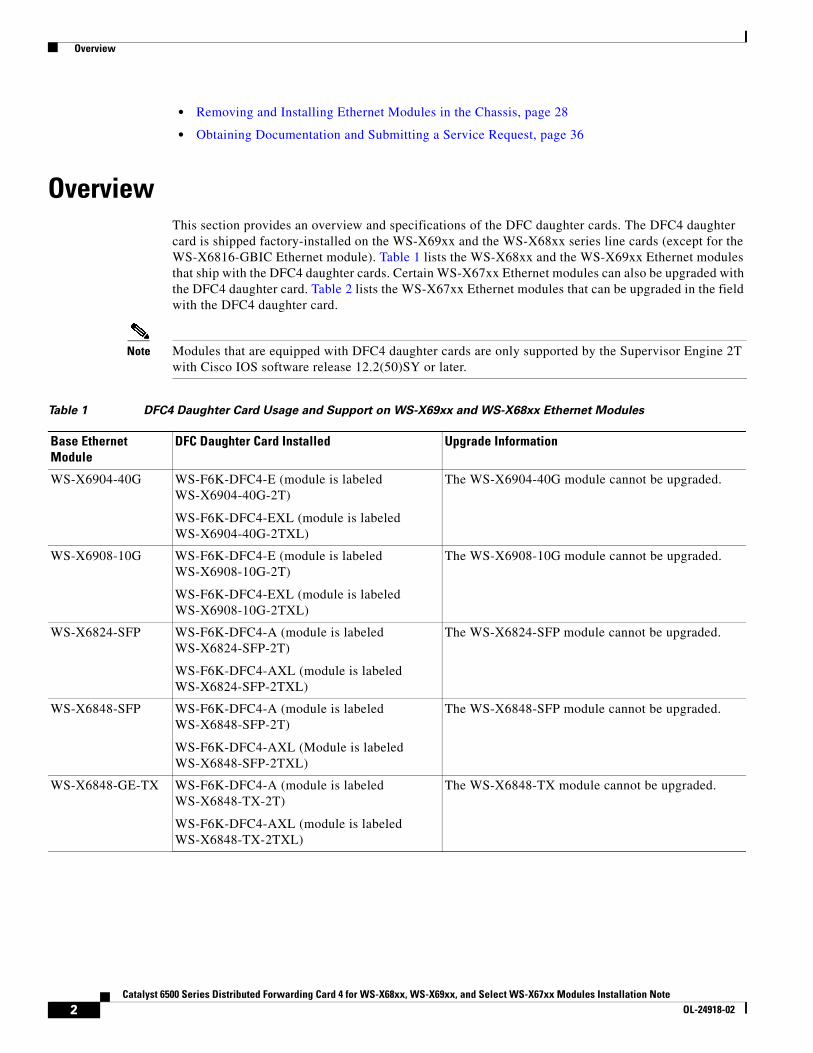
OverviewThis section provides an overview and specifications of the DFC daughter cards. The DFC4 daughter card is shipped factory-installed on the WS-X69xx and the WS-X68xx series line cards (except for the WS-X6816-GBIC Ethernet module). Table 1 lists the WS-X68xx and the WS-X69xx Ethernet modules that ship with the DFC4 daughter cards. Certain WS-X67xx Ethernet modules can also be upgraded with the DFC4 daughter card. Table 2 lists the WS-X67xx Ethernet modules that can be upgraded in the field with the DFC4 daughter card.
Note Modules that are equipped with DFC4 daughter cards are only supported by the Supervisor Engine 2T with Cisco IOS software release 12.2(50)SY or later.
Table 1 DFC4 Daughter Card Usage and Support on WS-X69xx and WS-X68xx Ethernet Modules
Base Ethernet Module
DFC Daughter Card Installed Upgrade Information
WS-X6904-40G WS-F6K-DFC4-E (module is labeled WS-X6904-40G-2T)
WS-F6K-DFC4-EXL (module is labeled WS-X6904-40G-2TXL)
The WS-X6904-40G module cannot be upgraded.
WS-X6908-10G WS-F6K-DFC4-E (module is labeled WS-X6908-10G-2T)
WS-F6K-DFC4-EXL (module is labeled WS-X6908-10G-2TXL)
The WS-X6908-10G module cannot be upgraded.
WS-X6824-SFP WS-F6K-DFC4-A (module is labeled WS-X6824-SFP-2T)
WS-F6K-DFC4-AXL (module is labeled WS-X6824-SFP-2TXL)
The WS-X6824-SFP module cannot be upgraded.
WS-X6848-SFP WS-F6K-DFC4-A (module is labeled WS-X6848-SFP-2T)
WS-F6K-DFC4-AXL (Module is labeled WS-X6848-SFP-2TXL)
The WS-X6848-SFP module cannot be upgraded.
WS-X6848-GE-TX WS-F6K-DFC4-A (module is labeled WS-X6848-TX-2T)
WS-F6K-DFC4-AXL (module is labeled WS-X6848-TX-2TXL)
The WS-X6848-TX module cannot be upgraded.
2Catalyst 6500 Series Distributed Forwarding Card 4 for WS-X68xx, WS-X69xx, and Select WS-X67xx Modules Installation Note
OL-24918-02

Required Tools and Parts
Required Tools and Parts These parts are included in the DFC4 daughter card kit:
• DFC4-A, DFC4-AXL, DFC4-E, or DFC4-EXL daughter card
• One disposable grounding wrist strap
These tools and supplies are required to remove and install the DFC4 daughter card:
• Antistatic mat to support the removed module and an antistatic bag to store the removed DFC daughter card
• Your own ESD-prevention equipment or the disposable grounding wrist strap included in the upgrade kit
• Number 1 Phillips-head screwdriver for the DFC daughter card installation hardware
WS-X6816-10GE WS-F6K-DFC4-E (module is labeled WS-X6816-10G-2T)
WS-F6K-DFC4-EXL (module is labeled WS-X6816-10G-2TXL)
The WS-X6816-10G module cannot be upgraded.
WS-X6816-10T WS-F6K-DFC4-E (module is labeled WS-X6816-10T-2T)
WS-F6K-DFC4-EXL (module is labeled WS-X6816-10T-2TXL)
The WS-X6816-10T module cannot be upgraded.
Table 2 WS-X67xx Ethernet Modules that support the DFC4 Daughter Card Upgrade
Base Ethernet Module
DFC Daughter Card Installed Upgrade Information
WS-X6724-SFP CFC, DFC3A, DFC3B, DFC3BXL, DFC3C, or DFC3XL
Can be upgraded with either a WS-F6K-DFC4-A or a WS-F6K-DFC4-AXL
WS-X6748-SFP CFC, DFC3A, DFC3B, DFC3BXL, DFC3C, or DFC3XL
Can be upgraded with either a WS-F6K-DFC4-A or a WS-F6K-DFC4-AXL
WS-X6716-10GE DFC3A, DFC3B, DFC3BXL, DFC3C, or DFC3XL
Can be upgraded with either a WS-F6K-DFC4-E or a WS-F6K-DFC4-EXL
WS-X6748-GE-TX DFC3A, DFC3B, DFC3BXL, DFC3C, or DFC3XL
Can be upgraded with either a WS-F6K-DFC4-A or a WS-F6K-DFC4-AXL
WS-X6716-10T DFC3A, DFC3B, DFC3BXL, DFC3C, or DFC3XL
Can be upgraded with either a WS-F6K-DFC4-E or a WS-F6K-DFC4-EXL
WS-X6704-10GE DFC3A, DFC3B, DFC3BXL, DFC3C, or DFC3XL
Can be upgraded with either a WS-F6K-DFC4-A or a WS-F6K-DFC4-AXL
Table 1 DFC4 Daughter Card Usage and Support on WS-X69xx and WS-X68xx Ethernet Modules
Base Ethernet Module
DFC Daughter Card Installed Upgrade Information
3Catalyst 6500 Series Distributed Forwarding Card 4 for WS-X68xx, WS-X69xx, and Select WS-X67xx Modules Installation Note
OL-24918-02

Safety Overview
Safety OverviewSafety warnings appear throughout this publication in procedures that may harm you if performed incorrectly. A warning symbol precedes each warning statement.
Statement 1071—Warning Definition
Warning IMPORTANT SAFETY INSTRUCTIONS
This warning symbol means danger. You are in a situation that could cause bodily injury. Before you work on any equipment, be aware of the hazards involved with electrical circuitry and be familiar with standard practices for preventing accidents. Use the statement number provided at the end of each warning to locate its translation in the translated safety warnings that accompanied this device.
SAVE THESE INSTRUCTIONS
Waarschuwing BELANGRIJKE VEILIGHEIDSINSTRUCTIES
Dit waarschuwingssymbool betekent gevaar. U verkeert in een situatie die lichamelijk letsel kan veroorzaken. Voordat u aan enige apparatuur gaat werken, dient u zich bewust te zijn van de bij elektrische schakelingen betrokken risico's en dient u op de hoogte te zijn van de standaard praktijken om ongelukken te voorkomen. Gebruik het nummer van de verklaring onderaan de waarschuwing als u een vertaling van de waarschuwing die bij het apparaat wordt geleverd, wilt raadplegen.
BEWAAR DEZE INSTRUCTIES
Varoitus TÄRKEITÄ TURVALLISUUSOHJEITA
Tämä varoitusmerkki merkitsee vaaraa. Tilanne voi aiheuttaa ruumiillisia vammoja. Ennen kuin käsittelet laitteistoa, huomioi sähköpiirien käsittelemiseen liittyvät riskit ja tutustu onnettomuuksien yleisiin ehkäisytapoihin. Turvallisuusvaroitusten käännökset löytyvät laitteen mukana toimitettujen käännettyjen turvallisuusvaroitusten joukosta varoitusten lopussa näkyvien lausuntonumeroiden avulla.
SÄILYTÄ NÄMÄ OHJEET
Attention IMPORTANTES INFORMATIONS DE SÉCURITÉ
Ce symbole d'avertissement indique un danger. Vous vous trouvez dans une situation pouvant entraîner des blessures ou des dommages corporels. Avant de travailler sur un équipement, soyez conscient des dangers liés aux circuits électriques et familiarisez-vous avec les procédures couramment utilisées pour éviter les accidents. Pour prendre connaissance des traductions des avertissements figurant dans les consignes de sécurité traduites qui accompagnent cet appareil, référez-vous au numéro de l'instruction situé à la fin de chaque avertissement.
CONSERVEZ CES INFORMATIONS
4Catalyst 6500 Series Distributed Forwarding Card 4 for WS-X68xx, WS-X69xx, and Select WS-X67xx Modules Installation Note
OL-24918-02

Safety Overview
Warnung WICHTIGE SICHERHEITSHINWEISE
Dieses Warnsymbol bedeutet Gefahr. Sie befinden sich in einer Situation, die zu Verletzungen führen kann. Machen Sie sich vor der Arbeit mit Geräten mit den Gefahren elektrischer Schaltungen und den üblichen Verfahren zur Vorbeugung vor Unfällen vertraut. Suchen Sie mit der am Ende jeder Warnung angegebenen Anweisungsnummer nach der jeweiligen Übersetzung in den übersetzten Sicherheitshinweisen, die zusammen mit diesem Gerät ausgeliefert wurden.
BEWAHREN SIE DIESE HINWEISE GUT AUF.
Avvertenza IMPORTANTI ISTRUZIONI SULLA SICUREZZA
Questo simbolo di avvertenza indica un pericolo. La situazione potrebbe causare infortuni alle persone. Prima di intervenire su qualsiasi apparecchiatura, occorre essere al corrente dei pericoli relativi ai circuiti elettrici e conoscere le procedure standard per la prevenzione di incidenti. Utilizzare il numero di istruzione presente alla fine di ciascuna avvertenza per individuare le traduzioni delle avvertenze riportate in questo documento.
CONSERVARE QUESTE ISTRUZIONI
Advarsel VIKTIGE SIKKERHETSINSTRUKSJONER
Dette advarselssymbolet betyr fare. Du er i en situasjon som kan føre til skade på person. Før du begynner å arbeide med noe av utstyret, må du være oppmerksom på farene forbundet med elektriske kretser, og kjenne til standardprosedyrer for å forhindre ulykker. Bruk nummeret i slutten av hver advarsel for å finne oversettelsen i de oversatte sikkerhetsadvarslene som fulgte med denne enheten.
TA VARE PÅ DISSE INSTRUKSJONENE
Aviso INSTRUÇÕES IMPORTANTES DE SEGURANÇA
Este símbolo de aviso significa perigo. Você está em uma situação que poderá ser causadora de lesões corporais. Antes de iniciar a utilização de qualquer equipamento, tenha conhecimento dos perigos envolvidos no manuseio de circuitos elétricos e familiarize-se com as práticas habituais de prevenção de acidentes. Utilize o número da instrução fornecido ao final de cada aviso para localizar sua tradução nos avisos de segurança traduzidos que acompanham este dispositivo.
GUARDE ESTAS INSTRUÇÕES
¡Advertencia! INSTRUCCIONES IMPORTANTES DE SEGURIDAD
Este símbolo de aviso indica peligro. Existe riesgo para su integridad física. Antes de manipular cualquier equipo, considere los riesgos de la corriente eléctrica y familiarícese con los procedimientos estándar de prevención de accidentes. Al final de cada advertencia encontrará el número que le ayudará a encontrar el texto traducido en el apartado de traducciones que acompaña a este dispositivo.
GUARDE ESTAS INSTRUCCIONES
5Catalyst 6500 Series Distributed Forwarding Card 4 for WS-X68xx, WS-X69xx, and Select WS-X67xx Modules Installation Note
OL-24918-02

Safety Overview
Varning! VIKTIGA SÄKERHETSANVISNINGAR
Denna varningssignal signalerar fara. Du befinner dig i en situation som kan leda till personskada. Innan du utför arbete på någon utrustning måste du vara medveten om farorna med elkretsar och känna till vanliga förfaranden för att förebygga olyckor. Använd det nummer som finns i slutet av varje varning för att hitta dess översättning i de översatta säkerhetsvarningar som medföljer denna anordning.
SPARA DESSA ANVISNINGAR
6Catalyst 6500 Series Distributed Forwarding Card 4 for WS-X68xx, WS-X69xx, and Select WS-X67xx Modules Installation Note
OL-24918-02

Safety Overview
Aviso INSTRUÇÕES IMPORTANTES DE SEGURANÇA
Este símbolo de aviso significa perigo. Você se encontra em uma situação em que há risco de lesões corporais. Antes de trabalhar com qualquer equipamento, esteja ciente dos riscos que envolvem os circuitos elétricos e familiarize-se com as práticas padrão de prevenção de acidentes. Use o número da declaração fornecido ao final de cada aviso para localizar sua tradução nos avisos de segurança traduzidos que acompanham o dispositivo.
GUARDE ESTAS INSTRUÇÕES
Advarsel VIGTIGE SIKKERHEDSANVISNINGER
Dette advarselssymbol betyder fare. Du befinder dig i en situation med risiko for legemesbeskadigelse. Før du begynder arbejde på udstyr, skal du være opmærksom på de involverede risici, der er ved elektriske kredsløb, og du skal sætte dig ind i standardprocedurer til undgåelse af ulykker. Brug erklæringsnummeret efter hver advarsel for at finde oversættelsen i de oversatte advarsler, der fulgte med denne enhed.
GEM DISSE ANVISNINGER
7Catalyst 6500 Series Distributed Forwarding Card 4 for WS-X68xx, WS-X69xx, and Select WS-X67xx Modules Installation Note
OL-24918-02

Safety Overview
8Catalyst 6500 Series Distributed Forwarding Card 4 for WS-X68xx, WS-X69xx, and Select WS-X67xx Modules Installation Note
OL-24918-02

Safety Overview
Warning Only trained and qualified personnel should be allowed to install, replace, or service this equipment. Statement 1030
Warning Hazardous voltage or energy is present on the backplane when the system is operating. Use caution when servicing. Statement 1034
9Catalyst 6500 Series Distributed Forwarding Card 4 for WS-X68xx, WS-X69xx, and Select WS-X67xx Modules Installation Note
OL-24918-02

Removing a CFC or DFC3 Daughter Card
Removing a CFC or DFC3 Daughter CardIf you are upgrading one of the WS-X67xx Ethernet modules listed in Table 2 with a DFC4 daughter card, you must remove the CFC or the DFC3 daughter card before installing the new DFC4 daughter card. The following two procedures are provided:
• Removing the CFC Daughter Card, page 10
• Removing the DFC3 Daughter Card, page 14
Note Once you have replaced the DFC3 daughter card with a DFC4 daughter card, the module will only operate with the Supervisor Engine 2T.
Removing the CFC Daughter CardIf your WS-X67xx Ethernet module is equipped with a CFC daughter card, you must remove it before you install the DFC4 daughter card.
Warning During this procedure, wear grounding wrist straps to avoid ESD damage to the card. Do not directly touch the backplane with your hand or any metal tool, or you could shock yourself. Statement 94
To remove a CFC daughter card, follow these steps:
Step 1 Attach an ESD grounding strap to your wrist and to ground.
Step 2 Remove the Ethernet module from the Catalyst 6500 series switch.
If you are unsure about the correct procedure for removing a module from the switch chassis, refer to the “Removing and Installing Ethernet Modules in the Chassis” section on page 28 for removal instructions.
Step 3 Place the Ethernet module on an antistatic mat with the front of the module facing toward you.
10Catalyst 6500 Series Distributed Forwarding Card 4 for WS-X68xx, WS-X69xx, and Select WS-X67xx Modules Installation Note
OL-24918-02

Removing a CFC or DFC3 Daughter Card
Step 4 If you are upgrading a WS-X6748-GE-TX Ethernet module with a DFC4 daughter card and your WS-X4748-GE-TX module is equipped with a stiffener bracket that goes across the top of the heat sinks at the front of the module (see Figure 1), you must first remove the stiffener bracket before continuing with the CFC daughter card removal procedure. To remove the bracket, follow these substeps:
a. Loosen and remove the six phillips-head screws that secure the bracket to the module.
b. Carefully lift and remove the bracket from the module.
Caution Do not reinstall the stiffener bracket. After upgrading the WS-X6748-GE-TX Ethernet module with a DFC4 daughter card, the bracket can be discarded.
Figure 1 WS-X6748-GE-TX Ethernet Module Equipped with a Stiffener Bracket
3313
21
WS-X5530WS-X6748-GE-TX 48 PORT ETHERNET
Stiffenerbracket
11Catalyst 6500 Series Distributed Forwarding Card 4 for WS-X68xx, WS-X69xx, and Select WS-X67xx Modules Installation Note
OL-24918-02

Removing a CFC or DFC3 Daughter Card
Step 5 Use a Phillips-head screwdriver to remove the installation hardware, which consists of three securing screws and the two cap nuts. (See Figure 2.)
Figure 2 CFC Daughter Card Installation Hardware
WS-X5530
9971
4STATUS
WS-X6724-SFP 24PORT GIGABIT ETHERNET - SFP
1 2 3 4 5 6 7 8 9 10 11 12 13 14 15 16 71 18 19 20 21 22 23 24
Cap nuts (2)
Screws (3)
CFC daughter card
Heat sinks
Card removal tabs (2)
12Catalyst 6500 Series Distributed Forwarding Card 4 for WS-X68xx, WS-X69xx, and Select WS-X67xx Modules Installation Note
OL-24918-02

Removing a CFC or DFC3 Daughter Card
Step 6 To unseat the CFC daughter card from the Ethernet module, hold each tab at the rear of the CFC daughter card between your thumb and index finger, and gently press down on both tabs until the connectors are unseated. (See Figure 3.)
Caution Do not apply too much pressure on the tabs because you might cause damage to the module.
Figure 3 Unseating the CFC Daughter Card Connectors
Step 7 Gently lift the CFC daughter card with both hands and remove the CFC daughter card from the module and immediately place the CFC daughter card in an antistatic bag.
Step 8 Proceed to the “Installing a DFC4 Daughter Card” section on page 23.
WS-X5530
1200
46STATUS
WS-X6724-SFP 24PORT GIGABIT ETHERNET - SFP
1 2 3 4 5 6 7 8 9 10 11 12 13 14 15 16 71 18 19 20 21 22 23 24
Heat sinks
13Catalyst 6500 Series Distributed Forwarding Card 4 for WS-X68xx, WS-X69xx, and Select WS-X67xx Modules Installation Note
OL-24918-02

Removing a CFC or DFC3 Daughter Card
Removing the DFC3 Daughter CardIf your WS-X67xx Ethernet module is equipped with a DFC3 daughter card, you must remove it before you install the DFC4 daughter card.
Warning During this procedure, wear grounding wrist straps to avoid ESD damage to the card. Do not directly touch the backplane with your hand or any metal tool, or you could shock yourself. Statement 94
To remove the DFC3 daughter card from modules, follow these steps:
Step 1 Attach an ESD grounding strap to your wrist and to ground.
Step 2 Remove the Ethernet module from the chassis.
If you are unsure about the correct procedure for removing a module from the switch chassis, refer to the “Removing an Ethernet Module from the Chassis” section on page 28 for removal instructions.
Step 3 Place the Ethernet module on an antistatic mat with the front of the module facing toward you.
Step 4 If you are upgrading a WS-X6748-GE-TX Ethernet module with a DFC4 daughter card and your WS-X4748-GE-TX module is equipped with a stiffener bracket that goes across the top of the heat sinks at the front of the module (see Figure 1), you must first remove the stiffener bracket before continuing with the CFC daughter card removal procedure. To remove the bracket, follow these substeps:
a. Loosen and remove the six phillips-head screws that secure the bracket to the module.
b. Carefully lift and remove the bracket from the module.
Caution Do not reinstall the stiffener bracket. After upgrading the WS-X6748-GE-TX Ethernet module with a DFC4 daughter card, the bracket can be discarded.
Step 5 If your DFC daughter card has a small metal installation bracket as shown in Figure 4, use a No.1 Phillips-head screwdriver to remove the two cap nuts and the one screw securing the bracket. Set them aside along with the bracket. If there is no bracket, just remove the two cap nuts and the one screw.
Step 6 Remove the remaining installation hardware. (See Figure 4.)
Note The installation hardware shown in Figure 4 is for a DFC3B or DFC3BXL daughter card. The installation hardware for a DFC3C or a DFC3CXL daughter card consists of 6 screws, 2 cap nuts, and 1 standoff.
14Catalyst 6500 Series Distributed Forwarding Card 4 for WS-X68xx, WS-X69xx, and Select WS-X67xx Modules Installation Note
OL-24918-02

Removing a CFC or DFC3 Daughter Card
Figure 4 Removing the DFC3 Daughter Card Installation Hardware
Step 7 Partially reinstall the cap nut, rotating about 3 turns so that there is a space of about 1/8 inch (3 mm) between the bottom of the cap nut and the top of the DFC3 daughter card, as shown in Figure 5. The cap nut acts as a stop when you unseat the daughter card connector so that the DFC3 daughter card does not move horizontally and cause damage to the base board.
WS-X5530
1544
56
STATUS
WS-X6724-SFP 24PORT GIGABIT ETHERNET - SFP
1 2 3 4 5 6 7 8 9 10 11 12 13 14 15 16 71 18 19 20 21 22 23 24
Installationbracket. Mayor may notbe present.
15Catalyst 6500 Series Distributed Forwarding Card 4 for WS-X68xx, WS-X69xx, and Select WS-X67xx Modules Installation Note
OL-24918-02

Removing a CFC or DFC3 Daughter Card
Figure 5 Partially Installing the Cap Nut
Step 8 With your left hand, lift slightly at the location shown in Figure 6. While lifting with your left hand, rock the DFC3 daughter card up and down with your right hand, no more than half an inch in either direction, to unseat the DFC3 daughter card from the module.
Cap nut
Appx 1/8 inch
1200
47
16Catalyst 6500 Series Distributed Forwarding Card 4 for WS-X68xx, WS-X69xx, and Select WS-X67xx Modules Installation Note
OL-24918-02

Removing a CFC or DFC3 Daughter Card
Figure 6 Unseat the DFC3 Daughter Card from the Module
Step 9 Remove the one cap nut.
Step 10 Holding the DFC3 daughter card with both hands, gently lift it straight up from the module. (See Figure 7.) Immediately place the DFC3 daughter card in an antistatic bag.
WS-X5530
1200
48
STATUS
WS-X6724-SFP 24PORT GIGABIT ETHERNET - SFP
1 2 3 4 5 6 7 8 9 10 11 12 13 14 15 16 71 18 19 20 21 22 23 24
Lift here
Rock upand down
17Catalyst 6500 Series Distributed Forwarding Card 4 for WS-X68xx, WS-X69xx, and Select WS-X67xx Modules Installation Note
OL-24918-02

Removing a DFC4 Daughter Card
Figure 7 Removing the DFC3 Daughter Card from the Module
Removing a DFC4 Daughter Card
Warning During this procedure, wear grounding wrist straps to avoid ESD damage to the card. Do not directly touch the backplane with your hand or any metal tool, or you could shock yourself. Statement 94
To remove the DFC4 daughter card from an Ethernet module, follow these steps:
Step 1 Attach an ESD grounding strap to your wrist and to ground.
Step 2 Remove the Ethernet module from the chassis.
If you are unsure about the correct procedure for removing a module from the switch chassis, refer to the “Removing an Ethernet Module from the Chassis” section on page 28 for removal instructions.
Step 3 Place the Ethernet module on an antistatic mat with the front of the module facing toward you.
Step 4 Remove the DFC4 daughter card mounting hardware. See Figure 8 for removing the WS-F6K-DFC4-E or WS-F6K-EXL daughter card mounting hardware. See Figure 9 for removing the WS-F6K-DFC4-A or WS-F6K-DFC4-AXL daughter card mounting hardware.
WS-X5530
STATUS
WS-X6724-SFP 24PORT GIGABIT ETHERNET - SFP
1 2 3 4 5 6 7 8 9 10 11 12 13 14 15 16 71 18 19 20 21 22 23 24
Unseat the DFC powerconnector
Lift here
Lift here
18Catalyst 6500 Series Distributed Forwarding Card 4 for WS-X68xx, WS-X69xx, and Select WS-X67xx Modules Installation Note
OL-24918-02

Removing a DFC4 Daughter Card
Figure 8 Removing DFC4 Daughter Card Installation Hardware (WS-F6K-DFC4-A or -AXL)
Figure 9 Removing DFC4 Daughter Card Installation Hardware (WS-F6K-DFC4-E or -EXL)
WS-X5530
1544
56
STATUS
WS-X6724-SFP 24PORT GIGABIT ETHERNET - SFP
1 2 3 4 5 6 7 8 9 10 11 12 13 14 15 16 71 18 19 20 21 22 23 24
Installationbracket. Mayor may notbe present.
1930
18
19Catalyst 6500 Series Distributed Forwarding Card 4 for WS-X68xx, WS-X69xx, and Select WS-X67xx Modules Installation Note
OL-24918-02

Removing a DFC4 Daughter Card
Step 5 Partially reinstall a cap nut, rotating it about 3 turns so that there is a space of about 1/8 inch (3 mm) between the bottom of the cap nut and the top of the DFC4 daughter card, as shown in Figure 10. The cap nut acts as a stop when you unseat the daughter card connector so that the DFC4 daughter card does not move horizontally and cause damage to the Ethernet module.
Figure 10 Partially Installing the Cap Nut
Step 6 With your left hand, lift slightly at the location shown in Figure 11. While lifting with your left hand, rock the DFC4 daughter card up and down with your right hand, no more than half an inch in either direction, to unseat the DFC4 daughter card from the module.
Cap nut
Appx 1/8 inch
1200
47
20Catalyst 6500 Series Distributed Forwarding Card 4 for WS-X68xx, WS-X69xx, and Select WS-X67xx Modules Installation Note
OL-24918-02

Removing a DFC4 Daughter Card
Figure 11 Unseat the DFC4 Daughter Card from the Module
Step 7 Remove the one cap nut.
Step 8 Holding the DFC4 daughter card with both hands, gently lift it straight up from the module. (See Figure 12.) Immediately place the DFC4 daughter card on an antistatic mat or in an antistatic bag.
WS-X5530
1200
48
STATUS
WS-X6724-SFP 24PORT GIGABIT ETHERNET - SFP
1 2 3 4 5 6 7 8 9 10 11 12 13 14 15 16 71 18 19 20 21 22 23 24
Lift here
Rock upand down
21Catalyst 6500 Series Distributed Forwarding Card 4 for WS-X68xx, WS-X69xx, and Select WS-X67xx Modules Installation Note
OL-24918-02

Removing a DFC4 Daughter Card
Figure 12 Removing the DFC4 Daughter Card from the Module
WS-X5530
STATUS
WS-X6724-SFP 24PORT GIGABIT ETHERNET - SFP
1 2 3 4 5 6 7 8 9 10 11 12 13 14 15 16 71 18 19 20 21 22 23 24
Unseat the DFC powerconnector
Lift here
Lift here
22Catalyst 6500 Series Distributed Forwarding Card 4 for WS-X68xx, WS-X69xx, and Select WS-X67xx Modules Installation Note
OL-24918-02

Installing a DFC4 Daughter Card
Installing a DFC4 Daughter Card
Warning During this procedure, wear grounding wrist straps to avoid ESD damage to the card. Do not directly touch the backplane with your hand or any metal tool, or you could shock yourself. Statement 94
To install a DFC4 daughter card on an Ethernet module, follow these steps:
Step 1 Attach an ESD grounding strap to your wrist and to ground.
Step 2 Remove the new DFC4 daughter card and the mounting hardware from the packaging.
Note The DFC4 daughter card is designed to be installed on different modules; therefore, there may be more mounting holes on the DFC4 daughter card than there are standoffs on the module. Not all mounting holes on the DFC4 daughter card are used in all installations. Visually verify that there are standoffs beneath the mounting holes before installing the mounting hardware.
Step 3 Align the mounting holes on the DFC4 daughter card (see Figure 13) with the male standoffs on the module. (See Figure 14.) Make sure that the remaining mounting holes on the DFC4 daughter card are aligned with the remaining standoffs on the module.
Figure 13 Mounting Holes on the DFC4 Daughter Card
9936
1
Align with the male standoffs on the module
9936
1
23Catalyst 6500 Series Distributed Forwarding Card 4 for WS-X68xx, WS-X69xx, and Select WS-X67xx Modules Installation Note
OL-24918-02

Installing a DFC4 Daughter Card
Figure 14 Male Standoff Locations on the WS-X68xx Modules
Step 4 Ensure that the connectors on the DFC4 daughter card are aligned with the connectors on the module. Apply pressure to the area shown in Figure 15 to seat the power connector.
WS-X5530
9971
6
STATUS
WS-X6724-SFP 24PORT GIGABIT ETHERNET - SFP
1 2 3 4 5 6 7 8 9 10 11 12 13 14 15 16 71 18 19 20 21 22 23 24
Male standoffs
24Catalyst 6500 Series Distributed Forwarding Card 4 for WS-X68xx, WS-X69xx, and Select WS-X67xx Modules Installation Note
OL-24918-02

Installing a DFC4 Daughter Card
Figure 15 Seating the Power Connector
Caution Use care not to damage the connectors on the module. If you damage a connector, you will need to return the module to Cisco for repair.
Step 5 Position the installation bracket over the two male standoffs at the back of the DFC4 daughter card. Apply pressure only to the top of the bracket to fully seat the DFC4 daughter card on the module as shown in Figure 16.
Caution When seating the DFC daughter card, do not apply pressure to any other location on the DFC daughter card, especially the heat sinks. If you exert pressure on the heat sinks, they can break off of the components they are attached to.
WS-X5530
9971
8
STATUS
WS-X6724-SFP 24PORT GIGABIT ETHERNET - SFP
1 2 3 4 5 6 7 8 9 10 11 12 13 14 15 16 71 18 19 20 21 22 23 24
Apply pressure here to seat power connector
25Catalyst 6500 Series Distributed Forwarding Card 4 for WS-X68xx, WS-X69xx, and Select WS-X67xx Modules Installation Note
OL-24918-02

Installing a DFC4 Daughter Card
Figure 16 Seating the DFC4 Daughter Card on the Module
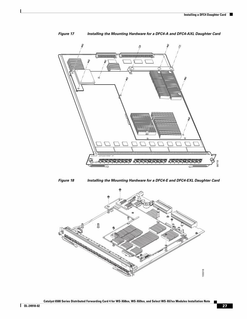
Step 6 Use a Phillips-head screwdriver to install the installation hardware:
a. For the DFC4-A and the DFC4-AXL daughter cards, install the 9 screws and the 2 standoffs. (See Figure 17.)
b. For the DFC4-E and the DFC4-EXL daughter cards, install the 6 screws, 2 cap nuts, and 1 standoff. (See Figure 18.)
Caution You must install all of the installation hardware. The screws provide grounding between the DFC4 daughter card and the Ethernet module. Failure to install all of the screws will invalidate the safety approvals and create a risk of fire and electrical hazard.
Note You should visually verify that there are standoffs beneath the mounting holes before installing the installation hardware.
WS-X5530
9971
7
STATUS
WS-X6724-SFP 24PORT GIGABIT ETHERNET - SFP
1 2 3 4 5 6 7 8 9 10 11 12 13 14 15 16 71 18 19 20 21 22 23 24
Apply pressure to bracket.to seat DFC connectors.
Do not press on heat sinks.
26Catalyst 6500 Series Distributed Forwarding Card 4 for WS-X68xx, WS-X69xx, and Select WS-X67xx Modules Installation Note
OL-24918-02
Installing a DFC4 Daughter Card
Figure 17 Installing the Mounting Hardware for a DFC4-A and DFC4-AXL Daughter Card
Figure 18 Installing the Mounting Hardware for a DFC4-E and DFC4-EXL Daughter Card
WS-X5530
9971
9
STATUS
WS-X6724-SFP 24PORT GIGABIT ETHERNET - SFP
1 2 3 4 5 6 7 8 9 10 11 12 13 14 15 16 71 18 19 20 21 22 23 24
1930
18
27Catalyst 6500 Series Distributed Forwarding Card 4 for WS-X68xx, WS-X69xx, and Select WS-X67xx Modules Installation Note
OL-24918-02

Removing and Installing Ethernet Modules in the Chassis
Caution If you have upgraded a WS-X6748-GE-TX Ethernet module that was equipped with a stiffener bracket, verify that you did not reinstall the stiffener bracket on the module. The bracket can be discarded.
Step 7 Reinstall the Ethernet module in the chassis.
If you are unsure about the correct procedure for installing an Ethernet module in the switch chassis, refer to the “Removing and Installing Ethernet Modules in the Chassis” section on page 28 for installation instructions.
Removing and Installing Ethernet Modules in the ChassisThis section describes how to correctly remove and install an Ethernet module in a Catalyst 6500 series switch chassis slot.
Note The WS-X68xx and the WS-X69xx Ethernet modules require that adjacent slots (above and below or to the left and to the right) that are empty have switching-module filler plates (Cisco part numbers WS-X6K-SLOT-CVR-E or SLOTBLANK-09). If either unused slot currently has a blank slot cover (Cisco part number WS-X6K-SLOT-CVR) installed, you must remove the blank slot cover and replace it with a switching-module filler plate for NEBS compliance.
Caution During this procedure, wear grounding wrist straps to avoid ESD damage to the card.
Warning Invisible laser radiation may be emitted from disconnected fibers or connectors. Do not stare into beams or view directly with optical instruments. Statement 272
Removing an Ethernet Module from the ChassisTo remove an Ethernet module from the chassis, perform these steps:
Step 1 Disconnect any network interface cables attached to the Ethernet module.
Step 2 Attach an ESD grounding strap to your wrist and to a proper ground.
Step 3 Verify that the captive installation screws on all of the modules in the chassis are tight. This step ensures that the space created by the removed module is maintained.
Note If the captive installation screws are loose, the electromagnetic interference (EMI) gaskets on the installed modules expand and push the modules toward the open slot, which reduces the opening size and makes it difficult to reinstall the module.
Step 4 Loosen the two captive installation screws on the Ethernet module.
28Catalyst 6500 Series Distributed Forwarding Card 4 for WS-X68xx, WS-X69xx, and Select WS-X67xx Modules Installation Note
OL-24918-02

Removing and Installing Ethernet Modules in the Chassis
Step 5 Depending on the orientation of the slots in the chassis (horizontal or vertical), perform one of the following two sets of substeps:
Horizontal slots
a. Place your thumbs on the left and right ejector levers located on the left and right sides of the module faceplate, and simultaneously rotate the levers outward to unseat the Ethernet module from the chassis backplane connector.
b. Grasp the front edge of the Ethernet module and slide the module part of the way out of the slot. Place your other hand under the Ethernet module to support the weight of the module. Do not touch the module circuitry.
c. Place the removed Ethernet module on a properly grounded antistatic mat or antistatic foam.
Vertical slots
a. Place your thumbs on the ejector levers located at the top and bottom of the Ethernet module, and simultaneously rotate the levers outward to unseat the Ethernet module from the chassis backplane connector.
b. Grasp the front edge of the Ethernet module and slide the module part of the way out of the slot. Place your other hand under the Ethernet module to support the weight of the module. Do not touch the module circuitry.
c. Place the removed Ethernet module on a properly grounded antistatic mat or antistatic foam.
Installing an Ethernet Module in the Chassis
Caution To prevent ESD damage, handle modules by the carrier edges only and wear grounding wrist straps.
Warning Invisible laser radiation may be emitted from disconnected fibers or connectors. Do not stare into beams or view directly with optical instruments. Statement 1051
To install a module in the chassis, perform these steps:
Step 1 Verify that an ESD grounding strap is attached to your wrist and to proper ground.
Step 2 Verify that the captive installation screws are tightened on all of the modules installed in the chassis. This step assures that the EMI gaskets on all of the installed modules are fully compressed in order to maximize the opening space for the Ethernet module.
Note If the captive installation screws are loose, the electromagnetic interference (EMI) gaskets on the installed modules expand and push the modules toward the open slot, which reduces the opening size and makes it difficult to reinstall the module.
29Catalyst 6500 Series Distributed Forwarding Card 4 for WS-X68xx, WS-X69xx, and Select WS-X67xx Modules Installation Note
OL-24918-02

Removing and Installing Ethernet Modules in the Chassis
Step 3 Fully open both ejector levers on the Ethernet module. (See Figure 19.)
Step 4 Depending on the orientation of the slots in the chassis (horizontal or vertical), perform one of the following two sets of substeps:
Horizontal slots
a. Position the Ethernet module in the slot. (See Figure 19.) Make sure that you align the edges of the module carrier with the slot guides on each side of the slot.
b. Carefully slide the Ethernet module into the slot until the EMI gasket along the top edge of the module makes contact with the module in the slot above it and both ejector levers have engaged and closed to approximately 45 degrees with respect to the Ethernet module faceplate. (See Figure 20.)
c. Using the thumb and forefinger of each hand, grasp the two ejector levers and press down to create a small (0.040 inch [1 mm]) gap between the module’s EMI gasket and the module above it. (See Figure 20.)
Caution Do not press down too hard on the levers because they can bend and be damaged.
d. While gently pressing down, simultaneously close the left and right ejector levers to fully seat the Ethernet module in the chassis backplane connector. The ejector levers are fully closed when they are flush with the module faceplate. (See Figure 21.)
Note Failure to fully seat the module in the chassis backplane connector can result in error messages.
e. Tighten the two captive installation screws on the Ethernet module.
Note Make sure that the ejector levers are fully closed before tightening the captive installation screws.
f. Verify that the Ethernet module STATUS LED is lit. Check the STATUS LED periodically. If the STATUS LED changes from orange to green, the module has successfully completed the boot process and is now online. If the STATUS LED remains orange or turns red, the module has not successfully completed the boot process and may have encountered an error.
30Catalyst 6500 Series Distributed Forwarding Card 4 for WS-X68xx, WS-X69xx, and Select WS-X67xx Modules Installation Note
OL-24918-02

Removing and Installing Ethernet Modules in the Chassis
Figure 19 Positioning the Module in a Horizontal Slot Chassis
1542
30
INPUTOK
FANOK
OUTPUTFAIL
o
INPUTOK
FANOK
OUTPUTFAIL
o
1
2
3
FANSTATUS
4
5
6
EMI gasket
EMI gasket
Insert module between slot guides
Ejector lever fully extended
4
3
55
4
6 6
WS-X6748-GE-TX 48 PORT ETHERNET
31Catalyst 6500 Series Distributed Forwarding Card 4 for WS-X68xx, WS-X69xx, and Select WS-X67xx Modules Installation Note
OL-24918-02

Removing and Installing Ethernet Modules in the Chassis
Figure 20 Clearing the EMI Gasket in a Horizontal Slot Chassis
Figure 21 Ejector Lever Closure in a Horizontal Slot Chassis
1
2
3
FANSTATUS
4
5
6
1 mm
24 PORT 100FX
WS-X6224
4
3
55
4
6 6
Gap between the moduleEMI gasket and the module above it
Press downPress down
1542
31
WS-X6748-GE-TX 48 PORT ETHERNET
1
2
3
FANSTATUS
4
5
6
1542
32
Ejector levers flushwith module faceplate
32Catalyst 6500 Series Distributed Forwarding Card 4 for WS-X68xx, WS-X69xx, and Select WS-X67xx Modules Installation Note
OL-24918-02

Removing and Installing Ethernet Modules in the Chassis
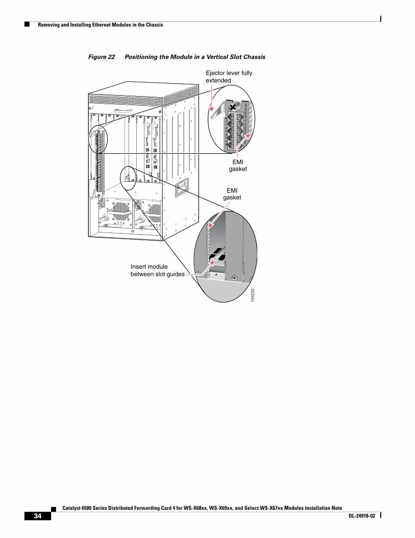
Vertical slots
a. Position the Ethernet module in the slot. (See Figure 22.) Make sure that you align the edges of the module carrier with the slot guides on the top and bottom of the chassis slot.
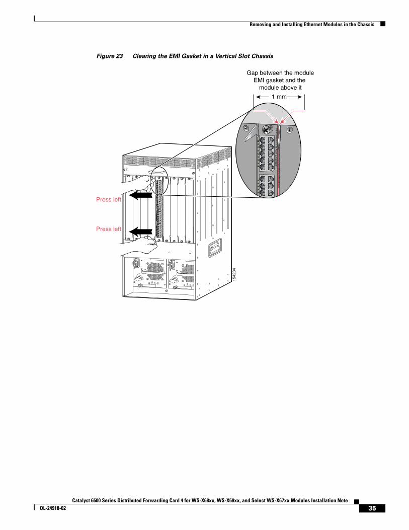
b. Carefully slide the Ethernet module into the slot until the EMI gasket along the right edge of the module faceplate makes contact with the module in the slot adjacent to it and both ejector levers have closed to approximately 45 degrees with respect to the Ethernet module faceplate. (See Figure 23.)
c. Using the thumb and forefinger of each hand, grasp the two ejector levers and exert a slight pressure to the left, deflecting the module approximately 0.040 inches (1 mm) to create a small gap between the module’s EMI gasket and the module adjacent to it. (See Figure 23.)
Caution Do not exert too much pressure on the ejector levers because they can bend and be damaged.
d. While gently pressing on the ejector levers, simultaneously close them to fully seat the Ethernet module in the chassis backplane connector. The ejector levers are fully closed when they are flush with the Ethernet module faceplate. (See Figure 24.)
e. Tighten the two captive installation screws on the Ethernet module.
Note Make sure that the ejector levers are fully closed before tightening the captive installation screws.
f. Verify that the Ethernet module STATUS LED is lit. Check the STATUS LED periodically. If the STATUS LED changes from orange to green, the module has successfully completed the boot process and is now online. If the STATUS LED remains orange or turns red, the module has not successfully completed the boot process and may have encountered an error.
33Catalyst 6500 Series Distributed Forwarding Card 4 for WS-X68xx, WS-X69xx, and Select WS-X67xx Modules Installation Note
OL-24918-02
Removing and Installing Ethernet Modules in the Chassis
Figure 22 Positioning the Module in a Vertical Slot Chassis
INPUTOK
FANOK
OUTPUTFAIL
o
INPUTOK
FANOK
OUTPUTFAIL
o
FANSTATUS
Ejector lever fully extended
4 3
6
WS
-X6748-G
E-T
X 48 P
OR
T E
TH
ER
NE
T
EMIgasket
EMIgasket
1542
33
Insert module between slot guides
34Catalyst 6500 Series Distributed Forwarding Card 4 for WS-X68xx, WS-X69xx, and Select WS-X67xx Modules Installation Note
OL-24918-02
Removing and Installing Ethernet Modules in the Chassis
Figure 23 Clearing the EMI Gasket in a Vertical Slot Chassis
INPUTOK
FANOK
OUTPUTFAIL
o
INPUTOK
FANOK
OUTPUTFAIL
o
FANSTATUS
1542
34
Gap between the moduleEMI gasket and the
module above it
1 mm
Press left
Press left
WS
-X6748-G
E-T
X 48 P
OR
T E
TH
ER
NE
T
35Catalyst 6500 Series Distributed Forwarding Card 4 for WS-X68xx, WS-X69xx, and Select WS-X67xx Modules Installation Note
OL-24918-02

Obtaining Documentation and Submitting a Service Request
Figure 24 Ejector Lever Closure in a Vertical Slot Chassis
Obtaining Documentation and Submitting a Service RequestFor information on obtaining documentation, submitting a service request, and gathering additional information, see the monthly What’s New in Cisco Product Documentation, which also lists all new and revised Cisco technical documentation, at:
http://www.cisco.com/en/US/docs/general/whatsnew/whatsnew.html
Subscribe to the What’s New in Cisco Product Documentation as a Really Simple Syndication (RSS) feed and set content to be delivered directly to your desktop using a reader application. The RSS feeds are a free service and Cisco currently supports RSS Version 2.0.
Cisco and the Cisco logo are trademarks or registered trademarks of Cisco and/or its affiliates in the U.S. and other countries. To view a list of Cisco trademarks, go to this URL: www.cisco.com/go/trademarks. Third-party trademarks mentioned are the property of their respective owners. The use of the word partner does not imply a partnership relationship between Cisco and any other company. (1110R)
© 2014 Cisco Systems, Inc. All rights reserved.
FANSTATUS
1542
35
All ejector levers flushwith module faceplate
36Catalyst 6500 Series Distributed Forwarding Card 4 for WS-X68xx, WS-X69xx, and Select WS-X67xx Modules Installation Note
OL-24918-02


![[XLS] and Construction... · Web view36 6500 30 3000 9 36 6500 62 4500 42 6500 37 3000 19 17 36 6500 42 6000 19 17 41 6500 36 3000 14 11 31 6500 33 6000 10 8 33 6500 31 3000 10 8](https://static.fdocuments.net/doc/165x107/5aaaff237f8b9a8f498b52b0/xls-and-constructionweb-view36-6500-30-3000-9-36-6500-62-4500-42-6500-37-3000.jpg)