Catalyst 2950 Software Configuration Guide - CCRIfaculty.ccri.edu/tonyrashid/Files/CCNA/Full.pdf ·...
340
Corporate Headquarters Cisco Systems, Inc. 170 West Tasman Drive San Jose, CA 95134-1706 USA http://www.cisco.com Tel: 408 526-4000 800 553-NETS (6387) Fax: 408 526-4100 Catalyst 2950 Desktop Switch Software Configuration Guide Cisco IOS Release 12.0(5)WC(1) April 2001 Customer Order Number: DOC-7811380= Text Part Number: 78-11380-01
Transcript of Catalyst 2950 Software Configuration Guide - CCRIfaculty.ccri.edu/tonyrashid/Files/CCNA/Full.pdf ·...

Catalyst 2950 Desktop Switch Software Configuration Guide
Cisco IOS Release 12.0(5)WC(1)April 2001
Corporate HeadquartersCisco Systems, Inc.170 West Tasman DriveSan Jose, CA 95134-1706USAhttp://www.cisco.comTel: 408 526-4000
800 553-NETS (6387)Fax: 408 526-4100
Customer Order Number: DOC-7811380=Text Part Number: 78-11380-01

THE SPECIFICATIONS AND INFORMATION REGARDING THE PRODUCTS IN THIS MANUAL ARE SUBJECT TO CHANGE WITHOUTNOTICE. ALL STATEMENTS, INFORMATION, AND RECOMMENDATIONS IN THIS MANUAL ARE BELIEVED TO BE ACCURATE BUTARE PRESENTED WITHOUT WARRANTY OF ANY KIND, EXPRESS OR IMPLIED. USERS MUST TAKE FULL RESPONSIBILITY FORTHEIR APPLICATION OF ANY PRODUCTS.
THE SOFTWARE LICENSE AND LIMITED WARRANTY FOR THE ACCOMPANYING PRODUCT ARE SET FORTH IN THE INFORMATIONPACKET THAT SHIPPED WITH THE PRODUCT AND ARE INCORPORATED HEREIN BY THIS REFERENCE. IF YOU ARE UNABLE TOLOCATE THE SOFTWARE LICENSE OR LIMITED WARRANTY, CONTACT YOUR CISCO REPRESENTATIVE FOR A COPY.
The Cisco implementation of TCP header compression is an adaptation of a program developed by the University of California, Berkeley (UCB) aspart of UCB’s public domain version of the UNIX operating system. All rights reserved. Copyright © 1981, Regents of the University of California.
NOTWITHSTANDING ANY OTHER WARRANTY HEREIN, ALL DOCUMENT FILES AND SOFTWARE OF THESE SUPPLIERS AREPROVIDED “AS IS” WITH ALL FAULTS. CISCO AND THE ABOVE-NAMED SUPPLIERS DISCLAIM ALL WARRANTIES, EXPRESSEDOR IMPLIED, INCLUDING, WITHOUT LIMITATION, THOSE OF MERCHANTABILITY, FITNESS FOR A PARTICULAR PURPOSE ANDNONINFRINGEMENT OR ARISING FROM A COURSE OF DEALING, USAGE, OR TRADE PRACTICE.
IN NO EVENT SHALL CISCO OR ITS SUPPLIERS BE LIABLE FOR ANY INDIRECT, SPECIAL, CONSEQUENTIAL, OR INCIDENTALDAMAGES, INCLUDING, WITHOUT LIMITATION, LOST PROFITS OR LOSS OR DAMAGE TO DATA ARISING OUT OF THE USE ORINABILITY TO USE THIS MANUAL, EVEN IF CISCO OR ITS SUPPLIERS HAVE BEEN ADVISED OF THE POSSIBILITY OF SUCHDAMAGES.
AccessPath, AtmDirector, Browse with Me, CCDA, CCDE, CCDP, CCIE, CCNA, CCNP, CCSI, CD-PAC, CiscoLink, the Cisco NetWorks logo, theCisco Powered Network logo, Cisco Systems Networking Academy, the Cisco Systems Networking Academy logo, Discover All That’s Possible,Fast Step, Follow Me Browsing, FormShare, FrameShare, GigaStack, IGX, Internet Quotient, IP/VC, iQ Breakthrough, iQ Expertise, iQ FastTrack,the iQ Logo, iQ Net Readiness Scorecard, MGX, the Networkers logo, Packet, PIX, RateMUX, ScriptBuilder, ScriptShare, SlideCast, SMARTnet,TransPath, Voice LAN, Wavelength Router, WebViewer are trademarks of Cisco Systems, Inc.; Changing the Way We Work, Live, Play, and Learn,Empowering the Internet Generation, are service marks of Cisco Systems, Inc.; and Aironet, ASIST, BPX, Catalyst, Cisco, the Cisco CertifiedInternetwork Expert logo, Cisco IOS, the Cisco IOS logo, Cisco Systems, Cisco Systems Capital, the Cisco Systems logo, Enterprise/Solver,EtherChannel, EtherSwitch, FastHub, FastSwitch, IOS, IP/TV, LightStream, MICA, Network Registrar, Post-Routing, Pre-Routing, Registrar,StrataView Plus, Stratm, SwitchProbe, TeleRouter, and VCO are registered trademarks of Cisco Systems, Inc. or its affiliates in the U.S. and certainother countries.
All other brands, names, or trademarks mentioned in this document or Web site are the property of their respective owners. The use of the wordpartner does not imply a partnership relationship between Cisco and any other company. (0101R)
Catalyst 2950 Desktop Switch Software Configuration GuideCopyright © 2001, Cisco Systems, Inc.All rights reserved.

78-11380-01
C O N T E N T S
Preface xv
Audience and Scope xv
Organization xv
Conventions xvi
Related Publications xvii
Notes, Tips, and Cautions xvii
Obtaining Documentation xviiiWorld Wide Web xviiiDocumentation CD-ROM xviiiOrdering Documentation xviiiDocumentation Feedback xix
Obtaining Technical Assistance xixCisco.com xxTechnical Assistance Center xx
Contacting TAC by Using the Cisco TAC Website xxContacting TAC by Telephone xxi
C H A P T E R 1 Overview 1-1
Key Features 1-2
Supported Hardware 1-3
Management Options 1-4Cisco Cluster Management Suite 1-4IOS Command-Line Interface 1-5SNMP Network Management Platforms 1-5
iiiCatalyst 2950 Desktop Switch Software Configuration Guide

Contents
Deployment Examples 1-6Enterprise Workgroup Aggregation 1-6Small to Medium-Sized Business Workgroup Aggregation 1-7
C H A P T E R 2 Using the Management Interfaces 2-1
Preparing to Use Cluster Management Suite 2-2Accessing CMS for the First Time 2-2
Using the Cluster Management Suite 2-3Using CMS Windows 2-3The Common Interface of Cluster Builder and Cluster View 2-5
Toolbar Icons for Cluster Builder and Cluster View 2-6Cluster View and Cluster Builder Device and Link Icons 2-7Menu Options for Cluster Builder and Cluster View 2-7
Using Cluster Builder 2-9Using Cluster View 2-13Using Cluster Manager 2-14
Menu Bar Options in Cluster Manager 2-15Using the Port Pop-Up Menu to Configure Ports 2-17Using the Device Pop-Up Menu to Configure a Switch 2-17Using the Cluster Tree 2-19Toolbar Icons for Cluster Manager 2-19
Using VSM 2-20VSM Menu Bar Options 2-22VSM Port Pop-Up Menu and Device Pop-Up Menu Options 2-24
Using Online Help 2-24
Using the IOS Command-Line Interface 2-24Understanding the CLI 2-25Setting Passwords and Privilege Levels 2-27Using the CLI to Manage Cluster Members 2-29Getting Help 2-30
ivCatalyst 2950 Desktop Switch Software Configuration Guide
78-11380-01

Contents
Abbreviating Commands 2-30Using no Commands 2-31Understanding Command-Line Error Messages 2-31Configuring the Switch for Telnet 2-32Starting a Telnet Session from the Browser 2-33Working with Files in Flash Memory 2-33
Using SNMP Management 2-34Using FTP to Access the MIB Files 2-35Using SNMP to Access MIB Variables 2-35Managing Cluster Switches Through SNMP 2-37Configuring the Switch for Remote Monitoring 2-38
C H A P T E R 3 Creating and Managing Clusters 3-1
Planning Your Cluster 3-2Creating Clusters with Different Releases of IOS Software 3-2Command Switch Requirements 3-3Candidate Switch Requirements 3-3Understanding Management VLAN Changes 3-4
Creating Clusters 3-5Enabling the Command Switch 3-5Automatically Discovering Cluster Candidates 3-6CLI: Creating a Cluster 3-8When a Cluster is Created 3-9
Changes to the Host Name 3-10Changes to the SNMP Community Strings 3-10Changes to Passwords 3-11
Adding and Removing Member Switches 3-12Determining Why a Switch Is Not Added to a Cluster 3-13CLI: Adding a Member to a Cluster 3-14CLI: Removing a Member from a Cluster 3-16
vCatalyst 2950 Desktop Switch Software Configuration Guide
78-11380-01

Contents
Building a Redundant Cluster 3-17Understanding HSRP 3-18Recovering from a Failed Command Switch without HSRP 3-19Configuring a Cluster Standby Group 3-19
Standby Command Switch Requirements 3-20Using the Standby Configuration Window 3-20CLI: Creating a Standby Group 3-22CLI: Adding Member Switches to a Standby Group 3-24CLI: Removing a Switch from a Standby Group 3-25CLI: Removing a Standby Group from the Network 3-26
Managing Switch Clusters 3-27Accessing the Cluster Management Suite 3-28Configuring Initial Cluster Settings 3-30
Arranging and Saving the Network Map 3-30Changing User Settings 3-31Rearranging the Order of the Displayed Switches 3-31Changing the Host Name 3-32
Saving Configuration Changes 3-33Displaying an Inventory of Cluster Switches 3-33Displaying Link Information 3-34Changing the Management VLAN 3-34
Guidelines for Changing the Management VLAN 3-35Changing the Management VLAN for a Cluster 3-35Changing the Management VLAN for a New Switch 3-37CLI: Changing the Management VLAN Through a Telnet Connection 3-37
Monitoring and Configuring Ports 3-38Monitoring Port Settings 3-39Monitoring Other Switch LEDs 3-41Guidelines for Configuring Ports 3-41
viCatalyst 2950 Desktop Switch Software Configuration Guide
78-11380-01

Contents
Connecting to Devices That Do Not Autonegotiate 3-41Configuring Ports 3-42Port Statistics 3-46Port Search 3-47CLI: Setting Speed and Duplex Parameters 3-49CLI: Configuring Flow Control on Gigabit Ethernet Ports 3-49
Displaying VLAN Membership 3-50Upgrading or Reloading the Switch Software 3-51
Guidelines for Upgrading or Reloading Switch Software 3-51Configuring the Cisco TFTP Server to Upgrade Multiple Switches 3-52CLI: Copying the Startup Configuration from the Switch to a PC or Server 3-52Using the Software Upgrade Page to Upgrade Switch Software 3-53CLI: Upgrading a Standalone Switch 3-55CLI: Reloading or Upgrading Catalyst 2950, 2900 XL, or 3500 XL Member Switches 3-57CLI: Upgrading Catalyst 1900 or 2820 Member Switches 3-58Reloading Switch Software 3-59
Configuring SNMP for a Cluster 3-59Enabling or Disabling the SNMP Agent 3-60Configuring Community Strings for Cluster Switches 3-60Configuring Trap Managers and Enabling Traps 3-63
C H A P T E R 4 Managing Switches 4-1
Finding More Information About IOS Commands 4-1
Managing Configuration Conflicts 4-2
Features, Default Settings, and Descriptions 4-2
Configuring Standalone Switches 4-9
Enabling the Switch as a Command Switch 4-10
Changing the Password 4-11
viiCatalyst 2950 Desktop Switch Software Configuration Guide
78-11380-01

Contents
Creating EtherChannel Port Groups 4-11Understanding EtherChannel Port Grouping 4-12Port Group Restrictions on Static-Address Forwarding 4-14CLI: Creating EtherChannel Port Groups 4-15
Enabling Switch Port Analyzer 4-15CLI: Enabling Switch Port Analyzer 4-17CLI: Disabling Switch Port Analyzer 4-18
Configuring Flooding Controls 4-18Enabling Storm Control 4-18
CLI: Enabling Storm Control 4-20CLI: Disabling Storm Control 4-21
Managing the System Date and Time 4-22Setting the System Date and Time 4-22Configuring Daylight Saving Time 4-23Configuring the Network Time Protocol 4-24
Configuring the Switch as an NTP Client 4-25Enabling NTP Authentication 4-26Configuring the Switch for NTP Broadcast-Client Mode 4-26
Configuring IP Information 4-26Manually Assigning IP Information to the Switch 4-27
CLI: Assigning IP Information to the Switch 4-28CLI: Removing an IP Address 4-29
DHCP-Based Autoconfiguration 4-29DHCP Client Request Process 4-30Configuring the DHCP Server 4-32Configuring the TFTP Server 4-33Configuring the DNS 4-33Configuring the Relay Device 4-34Obtaining Configuration Files 4-35Example Configuration 4-37
viiiCatalyst 2950 Desktop Switch Software Configuration Guide
78-11380-01

Contents
Specifying a Domain Name and Configuring the DNS 4-39Specifying the Domain Name 4-40Specifying a Name Server 4-41Enabling the DNS 4-41
Configuring SNMP 4-41Disabling and Enabling SNMP 4-42Entering Community Strings 4-42Adding Trap Managers 4-44CLI: Adding a Trap Manager 4-47
Managing the ARP Table 4-47
Managing the MAC Address Tables 4-49MAC Addresses and VLANs 4-50Changing the Address Aging Time 4-50
CLI: Configuring the Aging Time 4-51CLI: Removing Dynamic Address Entries 4-52
Adding Secure Addresses 4-52CLI: Adding Secure Addresses 4-54CLI: Removing Secure Addresses 4-55
Adding and Removing Static Addresses 4-55Configuring Static Addresses for EtherChannel Port Groups 4-57CLI: Adding Static Addresses 4-57CLI: Removing Static Addresses 4-58
Enabling Port Security 4-58Defining the Maximum Secure Address Count 4-60CLI: Enabling Port Security 4-61CLI: Disabling Port Security 4-62
Configuring the Cisco Discovery Protocol 4-62CLI: Configuring CDP for Extended Discovery 4-63
IGMP Snooping 4-64
ixCatalyst 2950 Desktop Switch Software Configuration Guide
78-11380-01

Contents
Enabling or Disabling IGMP Snooping 4-66CLI: Enabling or Disabling IGMP Snooping 4-67CLI: Enabling IGMP Immediate-Leave Processing 4-68Setting the Snooping Method 4-69
Joining a Multicast Group 4-70Statically Configuring a Host to Join a Group 4-72CLI: Statically Configuring a Interface to Join a Group 4-75
Leaving a Multicast Group 4-76Configuring a Multicast Router Port 4-76
CLI: Configuring a Multicast Router Port 4-79
Configuring the Spanning Tree Protocol 4-80Supported STP Instances 4-80Using STP to Support Redundant Connectivity 4-83Accelerating Aging to Retain Connectivity 4-83Disabling STP Protocol 4-83CLI: Disabling STP 4-84Configuring Redundant Links By Using STP UplinkFast 4-84CLI: Enabling STP UplinkFast 4-87Changing STP Parameters for a VLAN 4-87
CLI: Changing the STP Implementation 4-90CLI: Changing the Switch Priority 4-91CLI: Changing the BPDU Message Interval 4-92CLI: Changing the Hello BPDU Interval 4-92CLI: Changing the Forwarding Delay Time 4-93
Changing STP Port Parameters 4-93Enabling the Port Fast Feature 4-95CLI: Enabling STP Port Fast 4-97CLI: Changing the Path Cost 4-97CLI: Changing the Port Priority 4-98
CLI: Configuring STP Root Guard 4-98
xCatalyst 2950 Desktop Switch Software Configuration Guide
78-11380-01

Contents
CLI: Configuring UniDirectional Link Detection 4-100
Configuring Protected Ports 4-100CLI: Configuring Protected Ports 4-101
Configuring TACACS+ 4-101Understanding TACACS+ 4-102CLI Procedures for Configuring TACACS+ 4-102
CLI: Configuring the TACACS+ Server Host 4-103CLI: Configuring Login Authentication 4-104CLI: Specifying TACACS+ Authorization for EXEC Access and Network Services 4-105CLI: Starting TACACS+ Accounting 4-106CLI: Configuring a Switch for Local AAA 4-107
Configuring the Switch for Remote Monitoring 4-108
C H A P T E R 5 Creating and Maintaining VLANs 5-1
Number of Supported VLANs 5-2
VLAN Port Membership Modes 5-3VLAN Membership Combinations 5-3Clusters, VLAN Membership, and the Management VLAN 5-4
Assigning Static-Access Ports to a VLAN 5-5
Using the VLAN Trunk Protocol 5-6The VTP Domain 5-7VTP Modes and VTP Mode Transitions 5-8VTP Advertisements 5-9VTP Version 2 5-10VTP Configuration Guidelines 5-10
Domain Names 5-10Passwords 5-11VTP Version 5-11
xiCatalyst 2950 Desktop Switch Software Configuration Guide
78-11380-01

Contents
Default VTP Configuration 5-12Configuring VTP 5-12
CLI: Configuring VTP Server Mode 5-14CLI: Configuring VTP Client Mode 5-15CLI: Disabling VTP (VTP Transparent Mode) 5-16CLI: Enabling VTP Version 2 5-17CLI: Disabling VTP Version 2 5-18CLI: Monitoring VTP 5-18
VLANs in the VTP Database 5-19Token Ring VLANs 5-20VLAN Configuration Guidelines 5-20Default VLAN Configuration 5-21Configuring VLANs in the VTP Database 5-24
CLI: Adding an VLAN 5-25CLI: Modifying a VLAN 5-26CLI: Deleting a VLAN 5-27CLI: Assigning Static-Access Ports to a VLAN 5-28
How VLAN Trunks Work 5-29IEEE 802.1Q Configuration Considerations 5-30Trunks Interacting with Other Features 5-30Configuring a Trunk Port 5-31
CLI: Configuring a Trunk Port 5-32CLI: Disabling a Trunk Port 5-34CLI: Defining the Allowed VLANs on a Trunk 5-34CLI: Configuring the Native VLAN for Untagged Traffic 5-36
Configuring IEEE 802.1p Class of Service 5-37How Class of Service Works 5-37Port Priority 5-37Port Scheduling 5-37CLI: Configuring the CoS Port Priorities 5-38
xiiCatalyst 2950 Desktop Switch Software Configuration Guide
78-11380-01

Contents
CoS and WRR 5-39CLI: Configuring CoS Priority Queues 5-42CLI: Configuring WRR 5-43
Load Sharing Using STP 5-43Load Sharing Using STP Port Priorities 5-44CLI: Configuring STP Port Priorities and Load Sharing 5-45Load Sharing Using STP Path Cost 5-46CLI: Configuring STP Path Costs and Load Sharing 5-48
C H A P T E R 6 Creating Performance Graphs and Link Reports 6-1
Displaying Link Graphs 6-1Displaying the Percent Utilization 6-2Displaying the Bandwidth Utilization Graph 6-2
Displaying the Link Report 6-3
C H A P T E R 7 Troubleshooting 7-1
Autonegotiation Mismatches 7-1
Troubleshooting CMS Sessions 7-3
Recovery Procedures 7-4Recovering from Corrupted Software 7-5Recovering from a Lost or Forgotten Password 7-6Recovering from a Command Switch Failure 7-8
Replacing a Failed Command Switch with a Cluster Member 7-9Replacing a Failed Command Switch with Another Switch 7-12
Recovering from Lost Member Connectivity 7-14
A P P E N D I X A System Error Messages A-1
How to Read System Error Messages A-1
Error Message Traceback Reports A-4
xiiiCatalyst 2950 Desktop Switch Software Configuration Guide
78-11380-01

Contents
Error Message and Recovery Procedures A-4CMP Messages A-4Environment Messages A-5Link Messages A-6Port Security Messages A-6RTD Messages A-6Storm Control Messages A-7
I N D E X
xivCatalyst 2950 Desktop Switch Software Configuration Guide
78-11380-01

Preface
The Catalyst 2950 Desktop Switch Software Configuration Guide describes howto configure Catalyst 2950 switches by using the command-line interface (CLI)and web-based applications. This manual refers to these switches as the Catalyst2950 switches, or generically, as the switch.
Audience and ScopeThis guide is for the network manager responsible for configuring Catalyst 2950switches. We assume that you are familiar with the concepts and terminology ofEthernet and local area networking.
The scope of this guide is to provide the information you need to change theconfiguration of a switch, create and manage clusters of switches, andtroubleshoot problems that might arise.
OrganizationThis guide is organized into the following chapters:
Chapter 1, “Overview,” is a functional overview of the switch software. Itdescribes Cisco IOS Release 12.0(5)WC(1) features and lists the switches thatsupport the release. Examples show how you could deploy the switches.
Chapter 2, “Using the Management Interfaces,” describes how to use the differentmanagement interfaces.
xvCatalyst 2950 Desktop Switch Software Configuration Guide
78-11380-01

PrefaceConventions
Chapter 3, “Creating and Managing Clusters,” describes how to use the ClusterManagement Suite (CMS) and the command-line interface (CLI) to plan andcreate clusters of switches. The management activities described in this chapteroperate on clusters of switches.
Chapter 4, “Managing Switches,” describes how to use the web-based interfacesand the CLI to configure and monitor switches. The how-to information for usingthe web pages in this chapter is in the online help.
Chapter 5, “Creating and Maintaining VLANs,” describes how to configureVLANs in different network settings. You can configure VLANs on a singleswitch, by using trunk ports between switches, and by dynamically assigningVLAN membership.
Chapter 6, “Creating Performance Graphs and Link Reports,” describes how touse the CMS to generate performance graphs and link reports.
Chapter 7, “Troubleshooting,” describes how to identify and resolve some of theproblems that might arise when you are configuring a switch running this softwarerelease.
Appendix A, “System Error Messages,” describes the IOS system error messagesfor the Catalyst 2950 switches.
ConventionsThis publication uses the following conventions to convey instructions andinformation:
Command descriptions use these conventions:
• Commands and keywords are in boldface text.
• Arguments for which you supply values are in italic.
• Square brackets ([ ]) indicate optional elements.
• Braces ({ }) group required choices, and vertical bars ( | ) separate thealternative elements.
• Braces and vertical bars within square brackets ([{ | }]) indicate a requiredchoice within an optional element.
Interactive examples use these conventions:
• Terminal sessions and system displays are in screen font.
xviCatalyst 2950 Desktop Switch Software Configuration Guide
78-11380-01

PrefaceRelated Publications
• Information you enter is in boldface screen font.
• Nonprinting characters, such as passwords or tabs, are in angle brackets (< >).
Related PublicationsYou can order printed copies of documents with a DOC-xxxxxx= number. Formore information, see the “Obtaining Documentation” section on page xviii.
The following publications provide more information about the switches:
• Cisco Catalyst 2950 Desktop Switch Documentation CD
This CD is shipped with the switch and contains the following documents:
– This Cisco IOS Desktop Switching Software Configuration Guide,Cisco IOS Release 12.0(5)WC(1) (order number DOC-7811380=)
– Catalyst 2950 Desktop Switch Command Reference, Cisco IOSRelease 12.0(5)WC(1) (order number DOC-7811381=)
– Catalyst 2950 Desktop Switch Hardware Installation Guide (ordernumber DOC-7811157=)
• Release Notes for the Catalyst 2950 Cisco IOS Release 12.0(5)WC(1)
Notes, Tips, and CautionsNotes and cautions use the following conventions and symbols:
Note Means reader take note. Notes contain helpful suggestions or references tomaterials not contained in this manual.
Tips Means the following will help you solve a problem. The tips information mightnot be troubleshooting or even an action, but could be useful information.
xviiCatalyst 2950 Desktop Switch Software Configuration Guide
78-11380-01
PrefaceObtaining Documentation
Caution Means reader be careful. In this situation, you might do something that couldresult in equipment damage or loss of data.
Obtaining DocumentationThe following sections provide sources for obtaining documentation from CiscoSystems.
World Wide WebYou can access the most current Cisco documentation on the World Wide Web atthe following sites:
• http://www.cisco.com
• http://www-china.cisco.com
• http://www-europe.cisco.com
Documentation CD-ROMCisco documentation and additional literature are available in a CD-ROMpackage, which ships with your product. The Documentation CD-ROM is updatedmonthly and may be more current than printed documentation. The CD-ROMpackage is available as a single unit or as an annual subscription.
Ordering DocumentationCisco documentation is available in the following ways:
• Registered Cisco Direct Customers can order Cisco Product documentationfrom the Networking Products MarketPlace:
http://www.cisco.com/cgi-bin/order/order_root.pl
xviiiCatalyst 2950 Desktop Switch Software Configuration Guide
78-11380-01
PrefaceObtaining Technical Assistance
• Registered Cisco.com users can order the Documentation CD-ROM throughthe online Subscription Store:
http://www.cisco.com/go/subscription
• Nonregistered Cisco.com users can order documentation through a localaccount representative by calling Cisco corporate headquarters (California,USA) at 408 526-7208 or, in North America, by calling 800553-NETS(6387).
Documentation FeedbackIIf you are reading Cisco product documentation on the World Wide Web, you cansend us your comments by completing an online survey. When you display thedocument listing for this platform, click Give Us Your Feedback. If you are usingthe product-specific CD and you are connected to the Internet, click thepencil-and-paper icon in the toolbar to display the survey. After you display thesurvey, select the manual that you want to comment on. Click Submit to send yourcomments to the Cisco documentation group.
You can e-mail your comments to [email protected].
To submit your comments by mail, for your convenience many documents containa response card behind the front cover. Otherwise, you can mail your commentsto the following address:
Cisco Systems, Inc.Document Resource Connection170 West Tasman DriveSan Jose, CA 95134-9883
We appreciate your comments.
Obtaining Technical AssistanceCisco provides Cisco.com as a starting point for all technical assistance.Customers and partners can obtain documentation, troubleshooting tips, andsample configurations from online tools. For Cisco.com registered users,additional troubleshooting tools are available from the TAC website.
xixCatalyst 2950 Desktop Switch Software Configuration Guide
78-11380-01
PrefaceObtaining Technical Assistance
Cisco.comCisco.com is the foundation of a suite of interactive, networked services thatprovides immediate, open access to Cisco information and resources at anytime,from anywhere in the world. This highly integrated Internet application is apowerful, easy-to-use tool for doing business with Cisco.
Cisco.com provides a broad range of features and services to help customers andpartners streamline business processes and improve productivity. ThroughCisco.com, you can find information about Cisco and our networking solutions,services, and programs. In addition, you can resolve technical issues with onlinetechnical support, download and test software packages, and order Cisco learningmaterials and merchandise. Valuable online skill assessment, training, andcertification programs are also available.
Customers and partners can self-register on Cisco.com to obtain additionalpersonalized information and services. Registered users can order products, checkon the status of an order, access technical support, and view benefits specific totheir relationships with Cisco.
To access Cisco.com, go to the following website:
http://www.cisco.com
Technical Assistance CenterThe Cisco TAC website is available to all customers who need technical assistancewith a Cisco product or technology that is under warranty or covered by amaintenance contract.
Contacting TAC by Using the Cisco TAC Website
If you have a priority level 3 (P3) or priority level 4 (P4) problem, contact TACby going to the TAC website:
http://www.cisco.com/tac
xxCatalyst 2950 Desktop Switch Software Configuration Guide
78-11380-01

PrefaceObtaining Technical Assistance
P3 and P4 level problems are defined as follows:
• P3—Your network performance is degraded. Network functionality isnoticeably impaired, but most business operations continue.
• P4—You need information or assistance on Cisco product capabilities,product installation, or basic product configuration.
In each of the above cases, use the Cisco TAC website to quickly find answers toyour questions.
To register for Cisco.com, go to the following website:
http://www.cisco.com/register/
If you cannot resolve your technical issue by using the TAC online resources,Cisco.com registered users can open a case online by using the TAC Case Opentool at the following website:
http://www.cisco.com/tac/caseopen
Contacting TAC by Telephone
If you have a priority level 1(P1) or priority level 2 (P2) problem, contact TAC bytelephone and immediately open a case. To obtain a directory of toll-free numbersfor your country, go to the following website:
http://www.cisco.com/warp/public/687/Directory/DirTAC.shtml
P1 and P2 level problems are defined as follows:
• P1—Your production network is down, causing a critical impact to businessoperations if service is not restored quickly. No workaround is available.
• P2—Your production network is severely degraded, affecting significantaspects of your business operations. No workaround is available.
xxiCatalyst 2950 Desktop Switch Software Configuration Guide
78-11380-01

PrefaceObtaining Technical Assistance
xxiiCatalyst 2950 Desktop Switch Software Configuration Guide
78-11380-01

Catalyst 2950 Desktop Swi78-11380-01
C H A P T E R 1
OverviewCisco IOS Release 12.0(5)WC(1) supports the Catalyst 2950 switches. Theseworkgroup Ethernet switches can connect 10BASE-T, 100BASE-TX,100BASE-FX, and 1000BASE-T devices. The switches can connect to otherdevices as backbone switches, or they can be used in mixed configurations thatconnect hubs, servers, and end stations.
Table 1-1 on page 1-3 lists the switches that support this switch in a cluster.
This chapter provides information on the following topics:
• Key features
• Supported hardware
• Management options
• Deployment examples
1-1tch Software Configuration Guide

Chapter 1 OverviewKey Features
Key FeaturesThis section describes the key features of this software release. Table 4-2 onpage 4-3 lists each of these features with its default setting and a cross-referenceto the section describing it. This release has the following key features:
• Automatic discovery of candidates and creation of clusters of up to 16switches that can be managed through a single IP address. The ClusterManagement Suite (CMS) supports:
– Unified monitoring, configuration, and authentication of clusteredswitches through a web-based interface
– Management redundancy supported by the Hot Standby Router Protocol(HSRP)
– Extended discovery of cluster candidates for adding candidates that arenot directly connected to the command switch
• Support for IEEE 802.1p class of service (CoS) scheduling for classificationand preferential treatment of high-priority voice traffic
• Support for strict priority and weighted round-robin (WRR) CoS policies
• Support for the following virtual LAN (VLAN) options:
– IEEE 802.1Q trunking support on all ports
– Support for up to 64 VLANs
• Enhanced Spanning Tree Protocol (STP) features:
– STP support on a per-VLAN basis
– STP UplinkFast to accelerate the reconfiguration of STP
– STP root guard to prevent switches outside the network core frombecoming the STP root
• Terminal Access Controller Access Control System Plus (TACACS+) tomanage network security through a server
• Unidirectional link detection (UDLD) support on all Ethernet ports to preventunidirectional links
• Protected Port option for restricting the forwarding of traffic to designatedports on the same switch
1-2Catalyst 2950 Desktop Switch Software Configuration Guide
78-11380-01

Chapter 1 OverviewSupported Hardware
• Network Time Protocol (NTP) to provide an external source for time-of-dayinformation
• Internet Group Management Protocol (IGMP) snooping support to limitflooding of IP multicast traffic
• Dynamic Host Configuration Protocol (DHCP)-based autoconfiguration toensure retrieval of configuration files by unicast TFTP messages
Supported HardwareWhen switches are grouped into clusters, one switch is designated as thecommand switch, and the others are member switches. The IP address for theentire cluster is assigned to the command switch, and it distributes configurationand management information to the others. All Catalyst 2950 switches can act aseither command switches or member switches.
This section lists the switches and modules that support the Catalyst 2950switches in a cluster environment.
Note All switches can function as standalone devices.
Table 1-1 Switches Supporting Catalyst 2950 Switches in a Cluster
Configuration
Switch Models Software ReleaseMember Capable?
Command Capable?
2950 switches IOS Release12.0(5)WC(1)
Yes Yes
3500 XL switches IOS Release12.0(5)WC(1)
Yes Yes
2900 XL switches IOS Release
8 MB of DRAM 12.0(5)WC(1) Yes Yes
4 MB of DRAM 11.2(8.x)SA61 Yes No
1-3Catalyst 2950 Desktop Switch Software Configuration Guide
78-11380-01

Chapter 1 OverviewManagement Options
Management OptionsThis software release supports these management options:
• Cisco Cluster Management Suite
• Cisco IOS command-line interface (CLI)
• Simple Network Management Protocol (SNMP)
Cisco Cluster Management SuiteCMS is an integrated set of web-based applications. Use these applications tocreate clusters of switches, monitor real-time images of the switches, andconfigure both clustered and standalone switches.
The three CMS applications have the following functions:
• Cluster Manager displays the front panel and LEDs of all cluster switches.Within Cluster Manager, you can point-and-click to configure ports andswitches. You can select several ports from the same cluster and configurethem all to run with the same settings. All of the device-management featuresare available through the Cluster Manager menu bar.
• Visual Switch Manager (VSM) displays the front panel of one switch. VSMis the device-management application for individual and standalone switches.When creating a cluster, you use VSM to enable the command switch.
2820 switches Release 9.00(-A)
Release 9.00(-EN)
Yes
Yes
No
No
1900 switches Release 9.00(-A)
Release 9.00(-EN)
Yes
Yes
No
No
1. Original edition software. They can interoperate with this software release, but they cannot beupgraded to it.
Table 1-1 Switches Supporting Catalyst 2950 Switches in a Cluster
Configuration (continued)
Switch Models Software ReleaseMember Capable?
Command Capable?
1-4Catalyst 2950 Desktop Switch Software Configuration Guide
78-11380-01

Chapter 1 OverviewManagement Options
• Cluster Builder controls discovery of cluster candidates and cluster creation.It displays a network map that uses icons to display link speeds, clustermembers, cluster candidates, and edge devices. Cluster View displays anetwork map of the devices that are connected to a cluster, including otherclusters.
A browser plug-in is required to access the CMS. For more information, refer tothe Release Notes for the Catalyst 2950 Cisco IOS Release 12.0(5)WC(1).
IOS Command-Line InterfaceThis software release is based on Cisco IOS Release 12.0(5), but it has beenenhanced to support a set of desktop-switching features. Those commands thathave been added or changed for this software release are documented in this guideand in the Catalyst 2950 Desktop Switch Command Reference.
You can access the CLI by connecting a PC or terminal to the switch console portor by using Telnet. Chapter 2, “Using the Management Interfaces,” describes howto use the IOS CLI.
SNMP Network Management PlatformsYou can manage switches by using an SNMP-compatible management stationrunning such platforms as HP OpenView or SunNet Manager. In a clusterconfiguration, the command switch manages communication between the SNMPmanagement station and all switches in the cluster. The switch supports acomprehensive set of MIB extensions and MIB II, the IEEE 802.1D bridge MIB,and four Remote Monitoring (RMON) groups.
You can configure, monitor, and troubleshoot Catalyst 2950 switches by using theCiscoWorks2000 and CiscoView 5.0 network-management applications.
1-5Catalyst 2950 Desktop Switch Software Configuration Guide
78-11380-01

Chapter 1 OverviewDeployment Examples
Deployment ExamplesThis section describes how you can use this IOS release with the Catalyst 2950switches.
Enterprise Workgroup AggregationA Catalyst 3508G XL switch can be deployed to aggregate workgroup networkingdevices such as Ethernet 10/100 switches, 10BaseT and 10/100 hubs, workgroupservers, and Cisco 7960 IP Phones. The Catalyst 3508G XL switch can be thecommand switch for a single management point for the cluster. The commandswitch is assigned an IP address and manages other member switches (Catalyst2950, 2900 XL, and 3500 XL) deployed in an interconnected configuration.Figure 1-1 shows such a configuration.
1-6Catalyst 2950 Desktop Switch Software Configuration Guide
78-11380-01

Chapter 1 OverviewDeployment Examples
Figure 1-1 Enterprise Workgroup Aggregation
Small to Medium-Sized Business Workgroup AggregationA Catalyst 2950 switch can be used in a small to medium-sized business as anetwork backbone. It can aggregate Ethernet and Fast Ethernet network resourcesin the organization and provide 1000BaseTX connections to Gigabit Ethernetservers. Figure 1-2 shows such a configuration.
CascadedFast EtherChannelconnections
Closet A:Catalyst 2900 XLand Catalyst 2950member switches
Catalyst 2900 XLmember switch
Closet B:Catalyst 3500 XLmember switches
Closet C:Catalyst 2950
and Catalyst 3500 XLmember switches
Half-duplexGigaStackGBICconnections
Half-duplexGigaStackGBICconnections
PC
Cisco 7960IP Phones
3524-PWR
10BaseT/100BaseT
Full-duplexGigaStack GBICconnections
1000BaseX
Catalyst 3508G XLcommand switch
Catalyst 8500, 6000, or5500 series switch
4495
7
IP
IP
IP
1-7Catalyst 2950 Desktop Switch Software Configuration Guide
78-11380-01

Chapter 1 OverviewDeployment Examples
Figure 1-2 Small to Medium-Sized Business Workgroup Aggregation
Catalyst 2950switch
10 Mbps
Single workstations10BaseT/100BaseTworkstations
Catalyst 2950T-24switch
GigabitEthernetserver
4495
6
Catalyst 2950switch
1-8Catalyst 2950 Desktop Switch Software Configuration Guide
78-11380-01

Catalyst 2950 Desktop Swi78-11380-01
C H A P T E R 2
Using the Management InterfacesThis chapter describes the features and characteristics of the managementinterfaces available on the Catalyst 2950 switches. There is a command-lineinterface for entering IOS commands, a graphical user interface (GUI) for usewith a browser such as Microsoft Internet Explorer or Netscape Navigator, and aSimple Network Management Protocol (SNMP) interface for SNMP managementapplications such as CiscoWorks2000 and CiscoView 5.0.
This chapter describes the following topics:
• Preparing to use the Cluster Management Suite (CMS), the HTML-basedinterface for configuring clusters and individual switches
• Understanding the menu options, icons, and other graphical devices thatmake up the CMS interface
• Understanding how to change command modes and enter commands by usingthe IOS command-line interface (CLI)
• Understanding how to use an SNMP management application to manage acluster or switch
Note If you are looking for information on a specific feature, Table 4-2 on page 4-3lists the defaults for all key features and provides cross-references to featuredescriptions and CLI procedures.
2-1tch Software Configuration Guide

Chapter 2 Using the Management InterfacesPreparing to Use Cluster Management Suite
Preparing to Use Cluster Management SuiteAll of the CMS features are based on an embedded HTTP web server in the switchFlash memory.
CMS uses Hypertext Transfer Protocol (HTTP), which is an in-band form ofcommunication with the switch through any one of its Ethernet ports and thatallows switch management from a standard web browser. CMS requires that yourswitch uses HTTP port 80, which is the default HTTP port.
Note If you change the HTTP port, you cannot use CMS.
For information about connecting to a switch port, refer to the switch hardwareinstallation guide.
Do no disable or otherwise misconfigure the port through which yourmanagement station is communicating with the switch. You might want to writedown the port number to which you are connected. Changes to the switch IPinformation should be done with care.
Refer to the following topics in the Release Notes for the Catalyst 2950 Cisco IOSRelease 12.0(5)WC(1) for information about accessing CMS:
• System requirements
• Running the setup program
• Installing the required plug-in
• Configuring your web browser
• Accessing CMS
You access CMS through the default privilege level 15. For more information, seethe “Setting Passwords and Privilege Levels” section on page 2-27.
Accessing CMS for the First TimeUse the IP address of a cluster command switch or standalone switch to access theappropriate web-based application. For instructions on assigning the IP address,see the “CLI: Assigning IP Information to the Switch” section on page 4-28. Forinformation on clustering, see Chapter 3, “Creating and Managing Clusters.”
2-2Catalyst 2950 Desktop Switch Software Configuration Guide
78-11380-01

Chapter 2 Using the Management InterfacesUsing the Cluster Management Suite
If your network is configured with an HSRP standby group for redundancy, enterthe virtual IP address to access CMS. See the “Building a Redundant Cluster”section on page 3-17 for more information.
For detailed instructions to access Cluster Management, refer to the “AccessingCMS” section in the Release Notes for the Catalyst 2950 Cisco IOS Release12.0(5)WC(1).
Using the Cluster Management SuiteThe CMS consists of three related applications that you can use to create clustersof switches, configure and monitor switches and ports, and display link andperformance information. Each cluster requires a designated command switchwith an IP address to manage communication with the other switches in thecluster.
This section describes how you can use the following CMS applications tomanage your network:
• Cluster Builder and Cluster View
• Cluster Manager
• Visual Switch Manager (VSM)
These CMS applications support the monitoring and configuration of all clusterand switch features. VSM supports configuration and monitoring of alldevice-management features for standalone switches.
All CMS applications are supported by an online help system.
Using CMS WindowsCMS windows use consistent techniques to present and save configurationinformation. In some cases, CMS windows have multiple tabs that presentdifferent kinds of information. Tabs are arranged like folder headings across thetop of the window. Click the tab to display a new screen of information, and usethe Apply button to save information on all tabs without closing the window.
2-3Catalyst 2950 Desktop Switch Software Configuration Guide
78-11380-01

Chapter 2 Using the Management InterfacesUsing the Cluster Management Suite
When you are managing a cluster of switches, a drop-down Device List at the topof the window displays the names of all cluster switches. The contents of this listcan vary depending on the menu item selected. Click a switch to display theinformation for that switch. VSM windows, which always operate on a singleswitch, do not display a Device List.
Listed information can often be changed by selecting an item from a list. Tochange the information, select one or more items, and click Modify. Changingmultiple items is limited to those items that apply to at least one of the selections.For example, when you select multiple ports, a parameter such as flow control isgrayed out if the ports are not Gigabit Ethernet ports.
Tips If you try to select a port or device in Cluster Manager while there is anotherwindow still open, the computer issues a ringing bell sound. Rearrange thewindows that are displayed to find the open window, and close it to proceed.
Figure 2-1 shows the components of a typical CMS window.
The following are the most common buttons that you use to control a CMSwindow:
Button Description
OK Save any changes made in the window and close the window.
Apply Save any changes made in the window and leave the window open.
Cancel Do not save any changes made in the window and close the window.
Modify Display the pop-up for changing information on the selected item oritems. You usually select an item from a list or table and click Modify.When you close the pop-up, you return to the original window.
Help Display the online help for the current window and the online helptable of contents.
2-4Catalyst 2950 Desktop Switch Software Configuration Guide
78-11380-01

Chapter 2 Using the Management InterfacesUsing the Cluster Management Suite
Figure 2-1 Components of a CMS Window
The Common Interface of Cluster Builder and Cluster ViewCluster Builder and Cluster View are related applications that share the sameinterface. Use Cluster Builder to create and modify clusters of switches and todisplay a network map of their links and devices. You can create clusters withredundant command switches and display cluster members and the links betweenthem. Cluster View displays a map of the switches in a cluster and the neighboringedge devices and clusters. Once you have displayed Cluster Builder or ClusterView, you can toggle back and forth between the two.
The user interface for Cluster Builder and Cluster View consists of the networkmap—the switches, links, and other devices in the cluster—and the menus andtoolbar. The toolbar is a quick way to access features also available from the menubar.
Cluster switches are listed in the device list.
Click a tab to display more information.
Modify... displays a pop-up for the selected row.
Cancel closes the window without saving the changes.
Click in a row to select it.
Help displays help for the current window and the menu of Help topics.
OK saves the changes you have made and closes the window.
Apply saves the changes you have made and leaves the window open.
3267
6
2-5Catalyst 2950 Desktop Switch Software Configuration Guide
78-11380-01

Chapter 2 Using the Management InterfacesUsing the Cluster Management Suite
Toolbar Icons for Cluster Builder and Cluster View
One of the ways you can configure cluster switches is by clicking a toolbar icon.Figure 2-2 shows the Cluster Builder and Cluster View toolbar icons. Hold thecursor over an icon to display the feature invoked by that icon.
Figure 2-2 Features Available Through the Toolbar
You can invoke the following features from the Cluster Builder or Cluster Viewtoolbar (from left to right):
• Launch Cluster Manager.
• Toggle between Cluster Builder and Cluster View.
• Toggle between switch names and IP or MAC addresses and connected portnumbers.
• Save the presentation of the cluster icons as you have arranged them.
• Save the current configuration for all cluster members to Flash memory.
• Set the user settings for Cluster Builder and Cluster View.
• Display the legend that describes the icons, labels, and links that are used inCluster Builder and Cluster View.
• List the online help topics for Cluster Builder and Cluster View.
3265
4
Move the cursor over the icon to display the tool tip.
2-6Catalyst 2950 Desktop Switch Software Configuration Guide
78-11380-01

Chapter 2 Using the Management InterfacesUsing the Cluster Management Suite
Cluster View and Cluster Builder Device and Link Icons
The Cluster Builder and Cluster View legend shows the meaning of the coloredlabels and icons that represent the links and devices that make up the cluster.Select Help > Legend to display the legend. Figure 2-3 shows the device iconsand as they display on the network map. Display the link and label icons byclicking the respective tabs.
Figure 2-3 Icons Used in Cluster Builder and Cluster View
Menu Options for Cluster Builder and Cluster View
Table 2-1 lists the menu options and the tasks you can perform with ClusterBuilder and Cluster View.
Display the meaning of the links icons.
Device icons as they appear on Cluster Builder and Cluster View.
Display the meaning of the label icons.
3265
5
Table 2-1 Menu Options for Cluster Builder and Cluster View
Menu Bar Choices Task
Cluster
Add to cluster Add candidates to cluster.
Remove from cluster Remove members from cluster.
User Settings Change the default settings for the number of hopsto discover and the polling interval for ClusterBuilder and the link graphs.
2-7Catalyst 2950 Desktop Switch Software Configuration Guide
78-11380-01

Chapter 2 Using the Management InterfacesUsing the Cluster Management Suite
Cluster Manager Start Cluster Manager.
Views
Toggle Views Toggle between Cluster Builder and Cluster View.
Toggle Labels Toggle between switch names and IP or MACaddresses and connected port numbers.
Device
Launch SwitchManager
Start Switch Manager for a selected switch.
Bandwidth Graph Display a graph showing the current bandwidth inuse by a selected switch.
Show/Hide Candidates Expand or collapse image of all candidatesconnected to a cluster member.
Host NameConfiguration
Change the host name for a selected device.
Link
Link Graph Display a graph showing the bandwidth being usedfor the selected link.
Link Report Display the Link Report for two connected devices.If one device is an unknown device, candidate, orswitch, only the cluster member side of the linkdisplays.
Options
Save Layout Save the current presentation of the network map.
Save Configuration Save the current configuration of cluster membersto Flash memory.
Help
Contents List all of the available online help topics.
Table 2-1 Menu Options for Cluster Builder and Cluster View (continued)
Menu Bar Choices Task
2-8Catalyst 2950 Desktop Switch Software Configuration Guide
78-11380-01

Chapter 2 Using the Management InterfacesUsing the Cluster Management Suite
Using Cluster BuilderFollow the procedure in the “Accessing CMS” section in the Release Notes for theCatalyst 2950 Cisco IOS Release 12.0(5)WC(1) to display Cluster Builder. Whenyou are using Cluster Manager, click the double-switch icon on the toolbar(Figure 2-2) to toggle back to Cluster Builder.
Use Cluster Builder to create and manage a cluster of switches. Switchesconnected to the command switch or cluster-capable devices display themselvesas cluster members or candidates. Figure 2-4 shows Cluster Builder displaying amap of cluster devices.
Table 2-2 shows the meanings of the label colors in Cluster Builder. Table 2-3shows the meanings of the link colors in Cluster Builder. Table 2-4 shows themeanings of the icon colors in Cluster Builder.
Legend Display descriptions of the icons used on thenetwork map.
About ClusterBuilderView
Display the version number for Cluster Builder andCluster View.
Table 2-1 Menu Options for Cluster Builder and Cluster View (continued)
Menu Bar Choices Task
Table 2-2 Device Label Color Meanings in Cluster Builder
Label Color Color Meaning
Green A cluster member, either as a member switch or as thecommand switch.
Blue A cluster candidate that is fully qualified to become acluster member. Add these candidates with Cluster Builder.
White A standby command switch.
Yellow An unknown edge device that cannot become a member.
2-9Catalyst 2950 Desktop Switch Software Configuration Guide
78-11380-01

Chapter 2 Using the Management InterfacesUsing the Cluster Management Suite
Table 2-3 Link Color Meanings in Cluster Builder
Link Color Color Meaning
Dark blue Active link
Red Blocked link
Table 2-4 Icon Color Meanings in Cluster Builder
Label Color Color Meaning
Green Device is up.
Red Device is down.
Yellow Fault indication.
2-10Catalyst 2950 Desktop Switch Software Configuration Guide
78-11380-01

Chapter 2 Using the Management InterfacesUsing the Cluster Management Suite
Figure 2-4 Cluster Builder
Table 2-5 describes the available menu options when you right-click a candidateswitch.
Crown indicates the command switch.
Single lines are cluster connections of less than 100 Mbps.
Double lines are cluster connections of100 Mbps or more.
Lightning bolts are GigaStack GBICs.
2969
4
Table 2-5 Cluster Builder Candidate Pop-Up Menu
Menu Item Action
Device Web Page Displays the device-management page for the device.
Add to Cluster Adds the selected candidate or candidates to the cluster.
2-11Catalyst 2950 Desktop Switch Software Configuration Guide
78-11380-01

Chapter 2 Using the Management InterfacesUsing the Cluster Management Suite
Table 2-6 describes the available menu options when you right-click a memberswitch. For more information on configuring cluster members, see Chapter 4,“Managing Switches.”
Table 2-7 describes the available menu options when you right-click a link. Formore information on displaying link information, see Chapter 6, “CreatingPerformance Graphs and Link Reports.”
Table 2-6 Cluster Builder Member Pop-Up Menu
Menu Item Action
Switch Manager Display the VSM Home page for the selected device.
Bandwidth Graph Display a graph that plots the total bandwidth used bythe switch.
Host Name Config Change the name of the switch. For more information,see the “Changing the Host Name” section on page 3-32.
Remove from Cluster Remove the selected switch from the cluster.
Hide Candidates Toggle between displaying candidate switches and notdisplaying them.
Clear State Return switches that were down but are now up to thegreen (up) state. Switches that are yellow are down orwere previously down. Applicable only to yellowmember switches.
Table 2-7 Cluster Builder Link Pop-Up Items
Menu Item Action
Link Graph Display the performance graph for the link. One end of thelink must be connected to a port on a cluster member that is aCatalyst 2950, 2900 XL, or 3500 XL switch.
Link Report Displays information about the two ports in a link betweenmembers. If one end of the link is a candidate, the report onlydisplays information about the member switch.
2-12Catalyst 2950 Desktop Switch Software Configuration Guide
78-11380-01

Chapter 2 Using the Management InterfacesUsing the Cluster Management Suite
Using Cluster ViewCluster View displays a cluster as a double-switch icon with connections to edgedevices and candidate switches. To access Cluster View, select Views > ToggleViews from the menu bar in Cluster Builder. Table 2-8 describes the availablemenu options when you right-click an icon in Cluster View.
Figure 2-5 Cluster View
4721
5
Cluster is collapsed to a double-switch icon.
Connected cluster.
Switch 205
Switch 202 Switch 207nms-lab
172.20.128.252
2-13Catalyst 2950 Desktop Switch Software Configuration Guide
78-11380-01

Chapter 2 Using the Management InterfacesUsing the Cluster Management Suite
Using Cluster ManagerFor the detailed procedure to display Cluster Manager, refer to the Release Notesfor the Catalyst 2950 Cisco IOS Release 12.0(5)WC(1). When you are usingCluster Builder, click the double-switch icon on the toolbar (Figure 2-2) to toggleback to Cluster Manager.
Cluster Manager displays images of cluster switches that you can use to monitorand configure the devices. You can configure a cluster member on the port-,switch-, or cluster-level. With this release, many device-management features thatwere part of Visual Switch Manager (VSM) are available in Cluster Manager andVSM.
Figure 2-6 Cluster Manager
Table 2-8 Cluster View Device Menu Options
Menu Item Action
Device web page Displays the web management page for the device.
Disqualificationcode
Describes why the switch is not a cluster member orcandidate.
Select a switch from the list.
Tool bar.Menu bar.
Right-click switch chassis to display the device pop-up menu.
Right-click port to display port pop-up menu.
4719
2
2-14Catalyst 2950 Desktop Switch Software Configuration Guide
78-11380-01

Chapter 2 Using the Management InterfacesUsing the Cluster Management Suite
Menu Bar Options in Cluster Manager
Table 2-9 describes the options available from the Cluster Manager menu bar.
Table 2-9 Menu Bar Options Available in Cluster Manager
Menu Item Task
Cluster
Management VLAN Change the management VLAN for a cluster.
System TimeManagement
Configure the system time or configure the Network Time Protocol.
Standby CommandConfiguration
Create an HSRP standby group to provide command-switch redundancy.
Device Position Rearrange the order in which switches appear in Cluster Manager.
User Settings Set the polling interval for Cluster Manager, Cluster Builder, and theperformance graphs. Set the application to display by default.
Cluster Builder Display Cluster Builder.
System
Inventory Display the device type, software version, IP address, and otherinformation about a switch or a cluster of switches.
IP Management Configure IP information for a switch.
Software Upgrade Upgrade the software for a cluster or a switch.
SNMP Management Enter SNMP community strings and configure end stations as trapmanagers.
Console Baud Rate Change the baud rate of a switch console port.
ARP Table Display and maintain the Address Resolution Protocol (ARP) table.
Save Configuration Save the configuration on one or all of the cluster switches.
System Reload Reboot the software on a switch or a cluster.
Device
Spanning-TreeProtocol (STP)
Display and configure STP parameters for a switch.
2-15Catalyst 2950 Desktop Switch Software Configuration Guide
78-11380-01

Chapter 2 Using the Management InterfacesUsing the Cluster Management Suite
Internet GroupManagement Protocol(IGMP) Snooping
Enable and disable IGMP snooping and IGMP Immediate-Leaveprocessing on the switch. Join or leave multicast groups and configuremulticast routers.
CoS and WeightedRound Robin (WRR)
Assign packets to an output queue based on their priorities. Enable WRRand assign relative weights to the output queues.
Port
Port Configuration Display and configure port parameters on a switch.
Port Statistics Display detailed port statistics on link performance, dropped packets, andtotal errors.
Port Search Search for ports based on a description criteria.
Port Grouping (EC) Group ports into logical units for high-speed links between switches.
Switch Port Analyzer(SPAN)
Enable SPAN port monitoring.
Flooding Control Enable broadcast, unicast, and multicast flooding storm control.
VLAN
VLAN Membership Display VLAN membership, assign ports to VLANs, and configure IEEE802.1Q trunks.
VTP Management Display and configure the VLAN Trunk Protocol (VTP) for interswitchVLAN membership.
Security
Address Management Enter dynamic, secure, and static addresses into a switch address table, anddefine the forwarding behavior of static addresses.
Port Security Enable port security on a port.
Help
Contents List all of the available online help topics.
Legend Display the legend that describes the icons, labels, and links.
About Cluster Manager Display the version number for Cluster Manager.
Table 2-9 Menu Bar Options Available in Cluster Manager (continued)
Menu Item Task
2-16Catalyst 2950 Desktop Switch Software Configuration Guide
78-11380-01
Chapter 2 Using the Management InterfacesUsing the Cluster Management Suite
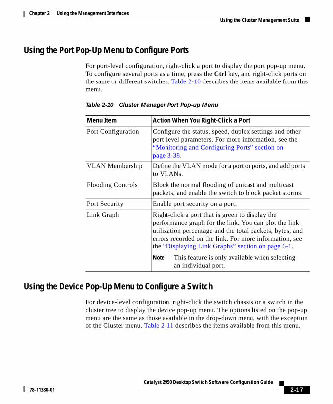
Using the Port Pop-Up Menu to Configure Ports
For port-level configuration, right-click a port to display the port pop-up menu.To configure several ports as a time, press the Ctrl key, and right-click ports onthe same or different switches. Table 2-10 describes the items available from thismenu.
Using the Device Pop-Up Menu to Configure a Switch
For device-level configuration, right-click the switch chassis or a switch in thecluster tree to display the device pop-up menu. The options listed on the pop-upmenu are the same as those available in the drop-down menu, with the exceptionof the Cluster menu. Table 2-11 describes the items available from this menu.
Table 2-10 Cluster Manager Port Pop-up Menu
Menu Item Action When You Right-Click a Port
Port Configuration Configure the status, speed, duplex settings and otherport-level parameters. For more information, see the“Monitoring and Configuring Ports” section onpage 3-38.
VLAN Membership Define the VLAN mode for a port or ports, and add portsto VLANs.
Flooding Controls Block the normal flooding of unicast and multicastpackets, and enable the switch to block packet storms.
Port Security Enable port security on a port.
Link Graph Right-click a port that is green to display theperformance graph for the link. You can plot the linkutilization percentage and the total packets, bytes, anderrors recorded on the link. For more information, seethe “Displaying Link Graphs” section on page 6-1.
Note This feature is only available when selectingan individual port.
2-17Catalyst 2950 Desktop Switch Software Configuration Guide
78-11380-01

Chapter 2 Using the Management InterfacesUsing the Cluster Management Suite
Table 2-11 Cluster Manager Device Pop-up Menu
Menu Bar Choices Task
System
Inventory Displays the device type, software version, IP address, and otherinformation about a switch or cluster of switches.
IP Management Configure IP information for a switch.
Software Upgrade Upgrade the software for a cluster or a switch.
SNMP Management Enter SNMP community strings and configure end stations as trapmanagers.
Console Baud Rate Change the baud rate for one or more switches.
ARP Table Manage the Address Resolution Protocol (ARP) table.
Save Configuration Save the configuration on one or all of the cluster switches.
System Reload Reboot the software on a switch or a cluster.
Device
Spanning Tree Protocol(STP)
Display and configure STP parameters for a switch.
IGMP Snooping Enable and disable IGMP snooping and IGMP Immediate-Leaveprocessing on the switch. Join or leave multicast groups andconfigure multicast routers.
CoS and WRR Assign packets to an output queue based on their priorities. EnableWRR and assign relative weights to the output queues.
Port
Port Configuration Display and configure port parameters on a switch.
Port Statistics Display detailed port statistics on link performance, droppedpackages, and total errors.
Port Search Search for ports based on a description criteria.
Port Grouping (EC) Group ports into logical units for high-speed links betweenswitches.
Switch Port Analyzer (SPAN) Enable SPAN port monitoring.
Flooding Control Enable broadcast, unicast, and multicast flooding storm control.
2-18Catalyst 2950 Desktop Switch Software Configuration Guide
78-11380-01

Chapter 2 Using the Management InterfacesUsing the Cluster Management Suite
Using the Cluster Tree
The cluster tree displays the name of the cluster and the status of cluster members.Left-click a switch icon in the cluster tree to select it, and right-click to displaythe device pop-up menu.
Toolbar Icons for Cluster Manager
You can click the toolbar icon to invoke some Cluster Manager features. As shownin Figure 2-7, a description of the icon displays when you move the cursor over it.
VLAN
VLAN Membership Display VLAN membership, assign ports to VLANs, and configureIEEE 802.1Q trunks.
VTP Management Display and configure the VLAN Trunk Protocol (VTP) forinterswitch VLAN membership.
Security
Address Management Enter dynamic, secure, and static addresses into a switch addresstable, and define the forwarding behavior of static addresses.
Port Security Enable port security on a port.
Bandwidth Graph Display a graph that plots the total bandwidth in use by the switch.For more information, see the “Displaying Link Graphs” section onpage 6-1.
Table 2-11 Cluster Manager Device Pop-up Menu (continued)
Menu Bar Choices Task
2-19Catalyst 2950 Desktop Switch Software Configuration Guide
78-11380-01

Chapter 2 Using the Management InterfacesUsing the Cluster Management Suite
Figure 2-7 Cluster Manager Toolbar Icons
Click a Cluster Manager toolbar to invoke the following features, from left toright:
• Start Cluster Builder
• Display the Software Upgrade window
• Display the SNMP Management window
• Display the VLAN Membership window
• Display the Spanning Tree Protocol window
• Display the Save Configuration window
• Display the User Settings window
• Display the legend that describes the icons, labels, and links
• Display the Help table of contents. (See Using Online Help, page 2-24)
Using VSMVSM is a web-based device-management application for configuring andmonitoring a clustered or standalone switch. If your switch is part of a cluster, youcan also perform many VSM tasks from within Cluster Manager.
Move the cursor over the icon to display the tool tip.
Cluster name.
4719
3
2-20Catalyst 2950 Desktop Switch Software Configuration Guide
78-11380-01

Chapter 2 Using the Management InterfacesUsing the Cluster Management Suite
For the detailed procedure to display VSM, refer to the Release Notes for theCatalyst 2950 Cisco IOS Release 12.0(5)WC(1). To display VSM from withinCluster Builder or Cluster View, click a switch, and select Device > LaunchSwitch Manager from the menu bar.
The VSM Home page displays a real-time image of the switch that you can use tomonitor and reconfigure the switch and switch ports. The images of the LEDsdisplayed by VSM convey the same information as the LEDs on the front panel ofthe switch. You can configure a port or ports by right-clicking them and selectinga item from the Port Pop-Up menu.
When you use VSM to reconfigure a switch, the change becomes part of therunning configuration of the switch. The image of the switch and VSM windowsalways display the switch running configuration. However, the runningconfiguration is not necessarily the startup configuration that is used when theswitch restarts. To ensure that your changes are saved after a restart in VSM,select System > Save Configuration from the menu bar. If you are using the CLI,you can save the configuration by entering the write memory command inprivileged EXEC mode.
Figure 2-8 VSM Home Page
4871
6
Right-click a port, and select Port Configuration to enable or disable the port and set the speed, duplex, Port Fast, and other port parameters.
STAT displays the port status, SPD displays the port speed, and FDUP displays the port duplex setting.
Left-click Mode to change the meaning of the port LEDs.
Press Ctrl, and left-click ports to select multiple ports.
2-21Catalyst 2950 Desktop Switch Software Configuration Guide
78-11380-01

Chapter 2 Using the Management InterfacesUsing the Cluster Management Suite
VSM Menu Bar Options
You can access the device-management features from the Home page menu bar.Table 2-12 describes the menu options and their function.
Table 2-12 Menu Bar Options Available in VSM
Menu Bar Choices Task
Cluster
Cluster CommandConfiguration
Enable a switch to act as the cluster command switch.
Cluster Management Display Cluster Manager or Cluster Builder.
System
Inventory Display the device type, software version, IP address, and otherinformation about a switch.
IP Management Configure IP information for a switch.
Software Upgrade Upgrade the software for the cluster or a switch.
System TimeManagement
Configure the system time or the Network Time Protocol (NTP).
SNMP Management Enter SNMP community strings and configure end stations as trapmanagers.
Console Baud Rate Change the baud rate for a switch.
ARP Table Display the device Address Resolution Protocol (ARP) table.
User Settings Change the polling intervals for clustering and graphing, and enable thedisplay of the splash page when VSM starts.
Save Configuration Save the configuration.
System Reload Reboot the software on a switch.
Device
Spanning-TreeProtocol (STP)
Display and configure STP parameters for a switch.
IGMP Snooping Enable and disable IGMP snooping and IGMP Immediate-Leaveprocessing on the switch. Join or leave multicast groups and configuremulticast routers.
2-22Catalyst 2950 Desktop Switch Software Configuration Guide
78-11380-01

Chapter 2 Using the Management InterfacesUsing the Cluster Management Suite
CoS and WRR Assign packets to an output queue based on their priorities. Enable WRRand assign relative weights to the output queues.
Port
Port Configuration Display and configure port parameters on a switch.
Port Statistics Display detailed port statistics on link performance, dropped packages,and total errors.
Port Search Search for ports based on a description criteria.
Port Grouping (EC) Group ports into logical units for high-speed links between switches.
Switch Port Analyzer(SPAN)
Enable SPAN port monitoring.
Flooding Control Note Enable broadcast, unicast, and multicast flooding stormcontrol.
VLAN
VLAN Membership Display VLAN membership, assign ports to VLANs, and configure802.1Q trunks.
Management VLAN Change the management VLAN on the switch.
VTP Management Display and configure the VLAN Trunk Protocol (VTP) for interswitchVLAN membership.
Security
Address Management Enter dynamic, secure, and static addresses into a switch address table.You can also define the forwarding behavior of static addresses.
Port Security Enable port security on a port.
Help
Contents List all of the available online help topics.
Legend Display the legend that describes the icons, labels, and links.
About Visual SwitchManager
Display the version number for Visual Switch Manager.
Table 2-12 Menu Bar Options Available in VSM (continued)
Menu Bar Choices Task
2-23Catalyst 2950 Desktop Switch Software Configuration Guide
78-11380-01
Chapter 2 Using the Management InterfacesUsing the IOS Command-Line Interface
VSM Port Pop-Up Menu and Device Pop-Up Menu Options
The options available through the port pop-up and device pop-up menus in VSMare the same as those described in Table 2-10 and Table 2-11.
Using Online HelpTo get online help for CMS, do either of the following:
• Select Help > Contents from the menu bar. The left pane of the Help windowdisplays the Contents tab of the help system. The right pane displaysinformation for the first topic on the tab.
• Click Help in whatever CMS window you are using. The left pane of the Helpwindow displays the Contents tab, positioned to the topic for the CMSwindow. The right pane displays information on how to use the CMS window.
You can navigate within the Help window to find whatever CMS information youneed. By expanding the topics on the Contents tab and scrolling, you can see thebreadth of topics in the help system. Double-click any one, and information for itappears in the right pane. A glossary is also available; it is the bottom topic on thetab. You can also find information by clicking the Index tab. Use its entry fieldand Find button to look for a specific entry, or scroll until you find what you need.Double-click an index entry, and information for it appears in the right pane.
In addition to these navigation features, the online help offers:
• Backward and Forward buttons to let you review previous topics and return.
• Numerous links within the help topics—links from concepts to task detailsand from highlighted terms to glossary entries.
Using the IOS Command-Line InterfaceThis section introduces the Cisco IOS command-line interface (CLI). TheCatalyst 2950 Desktop Switch Command Reference contains a completedescription of commands that have been created or changed for the Catalyst 2950switches.
2-24Catalyst 2950 Desktop Switch Software Configuration Guide
78-11380-01

Chapter 2 Using the Management InterfacesUsing the IOS Command-Line Interface
This section describes how to perform the following tasks:
• Understand the CLI and its command modes
• Use the CLI to manage member switches
• Set passwords
• Configure the switch for Telnet
• Work with files in Flash memory
Note Certain port features can conflict with one another. Review the “ManagingConfiguration Conflicts” section on page 4-2 before you change the portsettings.
Understanding the CLIThis section describes the Cisco IOS command-mode structure. Each commandmode supports specific Cisco IOS commands. For example, the interfacecommand is used only from global configuration mode.
The switch supports the following command modes:
• User EXEC
• Privileged EXEC
• VLAN database
• Global configuration
• Interface configuration
• Line configuration
Table 2-13 describes how to access each mode, the prompt you see in that mode,and how to exit the mode. The examples in the table use the host name switch.
2-25Catalyst 2950 Desktop Switch Software Configuration Guide
78-11380-01

Chapter 2 Using the Management InterfacesUsing the IOS Command-Line Interface
Table 2-13 Command Modes Summary
Modes Access Method Prompt Exit Method About This Mode1
User EXEC Begin a sessionwith your switch.
switch> Enter logout orquit.
Use this mode to
• Changeterminalsettings.
• Perform basictests.
• Displaysysteminformation.
PrivilegedEXEC
Enter the enablecommand while inuser EXEC mode.
switch# Enter disable toexit.
Use this mode toverify commandsyou have entered.Access to thismode should beprotected with apassword.
VLANdatabase
Enter the vlandatabase commandwhile in privilegedEXEC mode.
switch(vlan)# To exit toprivileged EXECmode, enter exit.
Use this mode toconfigureVLAN-specificparameters.
Globalconfiguration
Enter the configurecommand while inprivileged EXECmode.
switch(config)# To exit toprivileged EXECmode, enter exit orend, or pressCtrl-Z.
Use this mode toconfigureparameters thatapply to yourswitch as a whole.
2-26Catalyst 2950 Desktop Switch Software Configuration Guide
78-11380-01

Chapter 2 Using the Management InterfacesUsing the IOS Command-Line Interface
Setting Passwords and Privilege LevelsBecause many privileged EXEC commands are used to set operating parameters,you should password-protect these commands to prevent unauthorized use.
Catalyst 2950 switches have two commands for setting passwords:
• enable secret password (a very secure, encrypted password)
• enable password password (a less secure, unencrypted password)
You must enter one of these passwords to gain access to privileged EXEC mode.It is recommended that you use the enable secret password.
If you enter the enable secret command, the text is encrypted before it is writtento the config.text file, and it is unreadable. If you enter the enable passwordcommand, the text is written as entered to the config.text file where you canread it.
Interfaceconfiguration
Enter the interfacecommand (with aspecific interface)while in globalconfiguration mode.
switch(config-if)# To exit to globalconfigurationmode, enter exit.
To exit toprivileged EXECmode, enterCtrl-Z or end.
Use this mode toconfigureparameters for theEthernetinterfaces.
Lineconfiguration
Specify a line withthe line vty or lineconsole commandwhile in globalconfiguration mode.
switch(config-line)# To exit to globalconfigurationmode, enter exit.
To exit toprivileged EXECmode, enterCtrl-Z or end.
Use this mode toconfigureparameters for theterminal line.
1. For any of the modes, you can see a comprehensive list of the available commands by entering a question mark (?) at theprompt.
Table 2-13 Command Modes Summary (continued)
Modes Access Method Prompt Exit Method About This Mode1
2-27Catalyst 2950 Desktop Switch Software Configuration Guide
78-11380-01

Chapter 2 Using the Management InterfacesUsing the IOS Command-Line Interface
Note When set, the enable secret password takes precedence, and the enablepassword serves no purpose.
Both types of passwords can contain from 1 to 25 uppercase and lowercasealphanumeric characters, and both can start with a number. Spaces are also validpassword characters; for example, two words is a valid password. Leading spacesare ignored; trailing spaces are recognized. The password is case sensitive.
To remove a password, use the no version of the commands: no enable secret orno enable password. If you lose or forget your enable password, see the“Recovering from a Lost or Forgotten Password” section on page 7-6.
When the Cluster Builder suggests a candidate to add to a cluster, you enter thepassword of the candidate switch, if one was defined, and the switch joins thecluster. Then the member switch inherits the command switch password. For moreinformation on managing passwords for the Cluster Management Suite, see the“Changes to Passwords” section on page 3-11.
You can also specify up to 15 privilege levels and define passwords for them byusing the enable password [level level] {password} or enable secret [level level]{password} command. Level 1 is normal EXEC-mode user privileges. If you donot specify a level, the privilege level defaults to 15 (traditional enable privileges).
Note You need privilege level 15 to access VSM and the Cluster Management Suite.You must also use privilege level 15 if you configure the TACACS+ (TerminalAccess Controller Access Control System Plus) protocol from the CLI so thatall your HTTP connections will be authenticated through the TACACS+server.
You can specify a level, set a password, and give the password only to users whoneed to have access at this level. Use the privilege level global configurationcommand to specify commands accessible at various levels. For information onother IOS Release 12.0 commands, refer to the Cisco IOS Release 12.0documentation set available on Cisco.com.
2-28Catalyst 2950 Desktop Switch Software Configuration Guide
78-11380-01

Chapter 2 Using the Management InterfacesUsing the IOS Command-Line Interface
Using the CLI to Manage Cluster MembersYou can configure member switches from the CLI by first logging into thecommand switch. Enter the EXEC mode rcommand command and the memberswitch number to start a Telnet session (through a console or Telnet connection)and access the member switch CLI. Except when connecting to a Catalyst 1900or 2820 switch running standard edition software with the command switch atprivilege level 1 to 14, you are not prompted for a password because the memberswitch inherited the password of the command switch when it joined the cluster.
The following example shows how to log into member-switch 3 from thecommand-switch CLI:
switch# rcommand 3
If you do not know the member-switch number, enter the EXEC mode showcluster members command on the command switch.
For Catalyst 2950 switches, the Telnet session accesses the member-switch CLIat the same privilege level as on the command switch. The IOS commands thenoperate as usual. For instructions on configuring the Catalyst 2950 switch for aTelnet session, see the “Configuring the Switch for Telnet” section on page 2-32.
For Catalyst 1900 and 2820 switches running standard edition software, the Telnetsession accesses the menu console (the menu-driven interface) if the commandswitch is at privilege level 15. If the command switch is at privilege level 14, youare prompted for the password before being able to access the menu console.
Command switch privilege levels map to the Catalyst 1900 and 2820 memberswitches running standard and Enterprise Edition Software as follows:
• If the command switch privilege level is 1 to 14, the member switch isaccessed at privilege level 1.
• If the command switch privilege level is 15, the member switch is accessed atprivilege level 15.
The Catalyst 1900 and 2820 CLI is available only on switches running EnterpriseEdition Software.
2-29Catalyst 2950 Desktop Switch Software Configuration Guide
78-11380-01

Chapter 2 Using the Management InterfacesUsing the IOS Command-Line Interface
Getting HelpYou can use the question mark (?) and arrow keys to help you enter commands.
For a list of available commands in a command mode, enter a question mark:
switch> ?
To complete a command, enter a few known characters followed by a tab (with nospace):
switch# sh conf<tab>switch# sh configuration
For a list of command variables, enter the command followed by a space and aquestion mark:
switch> show ?
To redisplay a command you previously entered, press the up-arrow key. You cancontinue to press the up-arrow key for more commands.
Abbreviating CommandsYou only have to enter enough characters for the switch to recognize the commandas unique. This example shows how to enter the show configuration command:
switch# show conf
2-30Catalyst 2950 Desktop Switch Software Configuration Guide
78-11380-01

Chapter 2 Using the Management InterfacesUsing the IOS Command-Line Interface
Using no CommandsThe word no creates a no form of a command. The no form of a command doesthe following:
• Resets a command to its default values.
or
• Reverses the action of a command. For example, the command no shutdownreverses the shutdown of an interface.
Understanding Command-Line Error MessagesTable 2-14 lists some error messages that you might encounter while using theCLI to configure your switch.
Table 2-14 Common CLI Error Messages
Error Message Meaning How to Get Help% Ambiguouscommand: "showcon"
You did not enter enoughcharacters for your switch torecognize the command.
Reenter the command followed by a spaceand a question mark (?).
The possible keywords that you can enterwith the command are displayed.
% Incompletecommand.
You did not enter all of thekeywords or values required bythis command.
Reenter the command followed by a spaceand a question mark (?).
The possible keywords that you can enterwith the command are displayed.
% Invalid inputdetected at ‘^’marker.
You entered the commandincorrectly. The caret (^) marksthe point of the error.
Enter a question mark (?) to display all of thecommands that are available in thiscommand mode.
The possible keywords that you can enterwith the command are displayed.
2-31Catalyst 2950 Desktop Switch Software Configuration Guide
78-11380-01

Chapter 2 Using the Management InterfacesUsing the IOS Command-Line Interface
Configuring the Switch for TelnetFollow these steps to configure a Telnet password:
The “Finding More Information About IOS Commands” section on page 4-1contains the path to the complete IOS documentation.
Command Purpose
Step 1 Attach a PC or workstation with emulation software tothe switch console port.
The default data characteristics of the console port are9600, 8, 1, no parity. When the command line appears,go to Step 2.
Step 2 enable Enter privileged EXEC mode.
Step 3 config terminal Enter global configuration mode.
Step 4 line vty 0 15 Enter the interface configuration mode for the Telnetinterface.
There are 16 possible sessions on a command-capableswitch. The 0 and 15 mean that you are configuring all16 possible Telnet sessions.
Step 5 password <password> Enter a password.
Step 6 end Return to privileged EXEC mode so that you can verifythe entry.
Step 7 show running-config Display the running configuration.
The password is listed under the command line vty0 15
Step 8 copy running-configstartup-config
(Optional) Save the running configuration to thestartup configuration.
2-32Catalyst 2950 Desktop Switch Software Configuration Guide
78-11380-01

Chapter 2 Using the Management InterfacesUsing the IOS Command-Line Interface
Starting a Telnet Session from the BrowserFollow this procedure to start a Telnet session by using a browser:
Step 1 Start one of the supported browsers.
Step 2 In the URL field, enter the IP address of the command switch.
Step 3 When the Cisco Systems Access page appears, click Telnet - to the switch to startthe Telnet session.
Working with Files in Flash MemoryYou can use the file system in Flash memory to copy files and to troubleshootconfiguration problems. This could be useful if you wanted to save configurationfiles on an external server in case a switch fails. You can then copy theconfiguration file back to a replacement switch and avoid having to reconfigurethe switch.
As in the following example, use the privileged EXEC dir flash: command todisplay the contents of Flash memory:
Switch#dirDirectory of flash:/
3 drwx 10176 Mar 01 2001 00:04:34 html6 -rwx 2343 Mar 01 2001 03:18:16 config.text
171 -rwx 1667997 Mar 01 2001 00:02:39 c2950-c3h2s-mz.120-5.WC.1.bin7 -rwx 3060 Mar 01 2001 00:14:20 vlan.dat
172 -rwx 100 Mar 01 2001 00:02:54 env_vars
7741440 bytes total (4788224 bytes free)
The file system uses a URL-based file specification. The following example usesthe TFTP protocol to copy the file config.text from the host arno to the switchFlash memory:
switch# copy tftp://arno//2950/config.text flash:config.text
2-33Catalyst 2950 Desktop Switch Software Configuration Guide
78-11380-01

Chapter 2 Using the Management InterfacesUsing SNMP Management
You can enter the following parameters as part of a filename:
• TFTP
• Flash
• RCP
• XMODEM
Use the copy running-config startup-config command to save yourconfiguration changes to Flash memory so that they are not lost if there is a systemreload or power outage. This example shows how to use this command to saveyour changes:
switch# copy running-config startup-configBuilding configuration...
It might take a minute or two to save the configuration to Flash memory. After ithas been saved, the following message appears:
[OK]switch#
Using SNMP ManagementThis section describes how to access Management Information Base (MIB)objects to configure and manage your switch. It provides the followinginformation:
• Using FTP to access the MIB files
• Using Simple Network Management Protocol (SNMP) to access the MIBvariables
• Managing cluster switches through SNMP
Note When configuring your switch by using SNMP, note that certain combinationsof port features create configuration conflicts. For more information, see the“Managing Configuration Conflicts” section on page 4-2.
CiscoWorks2000 and CiscoView 5.0 are network-management applications youcan use to configure, monitor, and troubleshoot Catalyst 2950 switches.
2-34Catalyst 2950 Desktop Switch Software Configuration Guide
78-11380-01

Chapter 2 Using the Management InterfacesUsing SNMP Management
Using FTP to Access the MIB FilesYou can obtain each MIB file with the following procedure:
Step 1 Use FTP to access the server ftp.cisco.com.
Step 2 Log in with the username anonymous.
Step 3 Enter your e-mail username when prompted for the password.
Step 4 At the ftp> prompt, change directories to /pub/mibs/supportlists.
Step 5 Change directories to one of the following:
• wsc2900xl for a list of 2900 XL MIBs
• wsc3500xl for a list of 3500 XL MIBs
• wsc2950 for a list of 2950 MIBs
Step 6 Use the get MIB_filename command to obtain a copy of the MIB file.
You can also access this server from your browser by entering the following URLin the Location field of your Netscape browser (the Address field in InternetExplorer):
ftp://ftp.cisco.com
Use the mouse to navigate to the folders listed above.
Using SNMP to Access MIB Variables The switch MIB variables are accessible through SNMP, an application-layerprotocol facilitating the exchange of management information between networkdevices. The SNMP system consists of three parts:
• The SNMP manager, which resides on the network management system(NMS)
• The SNMP agent, which resides on the switch
• The MIBs that reside on the switch but that can be compiled with yournetwork management software
2-35Catalyst 2950 Desktop Switch Software Configuration Guide
78-11380-01

Chapter 2 Using the Management InterfacesUsing SNMP Management
An example of an NMS is the CiscoWorks network management software.CiscoWorks2000 software uses the switch MIB variables to set device variablesand to poll devices on the network for specific information. The results of a pollcan be displayed as a graph and analyzed in order to troubleshoot internetworkingproblems, increase network performance, verify the configuration of devices,monitor traffic loads, and more.
As shown in Figure 2-9, the SNMP agent gathers data from the MIB, which is therepository for information about device parameters and network data. The agentcan send traps, or notification of certain events, to the SNMP manager, whichreceives and processes the traps. Traps are messages alerting the SNMP managerto a condition on the network such as improper user authentication, restarts, linkstatus (up or down), and so forth. In addition, the SNMP agent responds toMIB-related queries sent by the SNMP manager in get-request, get-next-request,and set-request format.
The SNMP manager uses information in the MIB to perform the operationsdescribed in Table 2-15.
Figure 2-9 SNMP Network
Get-request, Get-next-request,Get-bulk, Set-request
Network device
Get-response, traps
S12
03a
SNMP Manager
NMS
MIBSNMP Agent
2-36Catalyst 2950 Desktop Switch Software Configuration Guide
78-11380-01

Chapter 2 Using the Management InterfacesUsing SNMP Management
Managing Cluster Switches Through SNMPSNMP must be enabled for the Cluster Management reporting and graphingfeatures to function properly. When you power-on your Catalyst 2950 switch forthe first time, SNMP is enabled if you enter the IP information by using the setupprogram and accept its proposed configuration. If you did not use the setupprogram to enter the IP information and SNMP was not enabled, you can enableit on the SNMP Configuration page described in the “Configuring SNMP” sectionon page 4-41. On Catalyst 1900 and 2820 switches, SNMP is enabled by default.
When a cluster is created, the command switch manages the exchange ofmessages between member switches and an SNMP application. The ClusterManagement software appends the member switch number (@esN, where N is theswitch number) to the first configured RW and RO community strings on thecommand switch and propagates them to the member switch. The commandswitch uses this community string to control the forwarding of gets, sets, andget-next messages between the SNMP management station and the memberswitches.
Note When a standby group is configured, the command switch can change withoutyour knowledge. Use the first read-write and read-only community strings tocommunicate with the command switch if there is a standby group configuredfor the cluster.
Table 2-15 SNMP Operations
Operation Description
get-request Retrieves a value from a specific variable.
get-next-request Retrieves a value from a variable within a table.1
1. With this operation, an SNMP manager does not need to know the exact variable name. Asequential search is performed to find the needed variable from within a table.
get-response Replies to a get-request, get-next-request, and set-request sentby an NMS.
set-request Stores a value in a specific variable.
trap An unsolicited message sent by an SNMP agent to an SNMPmanager indicating that some event has occurred.
2-37Catalyst 2950 Desktop Switch Software Configuration Guide
78-11380-01

Chapter 2 Using the Management InterfacesUsing SNMP Management
If the member switch does not have an IP address, the command switch passestraps from the member switch to the management station, as shown inFigure 2-10. If a member switch has its own IP address and community strings,they can be used in addition to the access provided by the command switch. Formore information, see the “Changes to the SNMP Community Strings” section onpage 3-10 and the “Configuring SNMP” section on page 4-41.
Figure 2-10 SNMP Management for a Cluster
Configuring the Switch for Remote MonitoringThis IOS software release supports four Remote Monitoring (RMON 1) groups.You can configure these groups by using an SNMP application or by using theCLI. The four supported groups are alarms, events, history, and statistics.
Trap
Trap
Trap
Command switch
Trap 1, trap 2, trap 3
Member 1 Member 2 Member 3
3302
0
SNMP Manager
2-38Catalyst 2950 Desktop Switch Software Configuration Guide
78-11380-01

Catalyst 2950 Desktop Swi78-11380-01
C H A P T E R 3
Creating and Managing ClustersA cluster is a group of connected switches that are managed as a single entity.The switches can be in the same location, or they can be distributed across acontiguous Layer 2 network. All communication with cluster switches is throughone IP address.
Tips You can have up to 16 switches in a cluster: 1 command switch and up to 15member switches. The command switch is the single point of access used tomanage, configure, and monitor the member switches.
Clusters can be configured for management redundancy by using the Hot StandbyRouter Protocol (HSRP). Figure 3-1 shows a cluster of switches with a standbycommand switch.
This chapter describes how to create and manage clusters of switches by using theCluster Management Suite (CMS) applications: Cluster Builder, Cluster View,and Cluster Manager. You use Cluster Builder to create the cluster, you useCluster View to display the devices connected to the cluster, and you use ClusterManager to configure and monitor your cluster after it has been created.
This chapter describes how to perform the following tasks:
• Planning your cluster
• Creating a cluster
• Building a redundant cluster
• Managing a cluster
3-1tch Software Configuration Guide
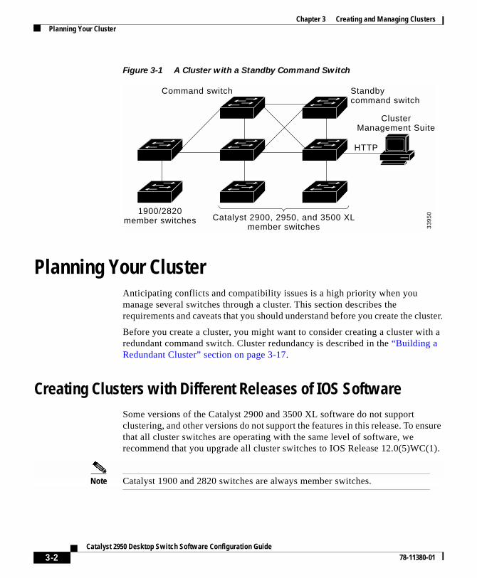
Chapter 3 Creating and Managing ClustersPlanning Your Cluster
Figure 3-1 A Cluster with a Standby Command Switch
Planning Your ClusterAnticipating conflicts and compatibility issues is a high priority when youmanage several switches through a cluster. This section describes therequirements and caveats that you should understand before you create the cluster.
Before you create a cluster, you might want to consider creating a cluster with aredundant command switch. Cluster redundancy is described in the “Building aRedundant Cluster” section on page 3-17.
Creating Clusters with Different Releases of IOS SoftwareSome versions of the Catalyst 2900 and 3500 XL software do not supportclustering, and other versions do not support the features in this release. To ensurethat all cluster switches are operating with the same level of software, werecommend that you upgrade all cluster switches to IOS Release 12.0(5)WC(1).
Note Catalyst 1900 and 2820 switches are always member switches.
Catalyst 2900, 2950, and 3500 XLmember switches
Command switch Standbycommand switch
ClusterManagement Suite
1900/2820member switches
HTTP
33
95
0
3-2Catalyst 2950 Desktop Switch Software Configuration Guide
78-11380-01

Chapter 3 Creating and Managing ClustersPlanning Your Cluster
Command Switch RequirementsYou must select a switch to be the command switch of your cluster. The commandswitch must satisfy the following requirements:
• It is running Cisco IOS Release 12.0(5)XU or later. See “SupportedHardware” section on page 1-3 for a list of switches that can run theseversions.
Note If you are running Cisco IOS Release 12.0(5)XW or earlier, a Catalyst 2950switch will show as an unknown device in Cluster Manager. In this case, youwill need to use Visual Switch Manager (VSM) to manage the Catalyst 2950switch.
• It is assigned an IP address.
• It has Cisco Discovery Protocol (CDP) version 2 enabled (the default).
• It is not a command or member switch of another cluster.
• It belongs to the same management virtual LAN (VLAN) as the clustermember switches.
• No access lists have been defined for the switch. Access lists can restrictaccess to a switch but are not usually used in configuring Catalyst 2950,2900 XL, or 3500 XL switches. (This does not include access class 199 thatis created when a device is configured as the command switch.)
Note To avoid losing contact with cluster members when a command switch fails,you might want to create a redundant cluster. For more information, see the“Building a Redundant Cluster” section on page 3-17.
Candidate Switch RequirementsBefore adding a candidate switch to the cluster, you must know any assignedenable or enable secret password.
3-3Catalyst 2950 Desktop Switch Software Configuration Guide
78-11380-01

Chapter 3 Creating and Managing ClustersPlanning Your Cluster
A candidate switch must satisfy the following requirements to join a cluster.
• It is running cluster-capable software. See the “Supported Hardware” sectionon page 1-3 for a list of switches that support clustering.
• It has CDP version 2 enabled.
• It is connected to a command switch through ports that belong to the samemanagement VLAN (see “Changing the Management VLAN” section onpage 3-34).
• It is not an active member or command switch of another cluster.
A candidate switch can have an IP address, but it is not required.
Note If you are unable to maintain management contact with a member, see the“Recovering from Lost Member Connectivity” section on page 7-14.
Understanding Management VLAN ChangesCommunication with the switch management interfaces is through the switch IPaddress. The IP address is associated with the management VLAN, which bydefault is VLAN 1. To manage switches in a cluster, the port connections amongthe command, member, and candidate switches must be connected through portsthat belong to the management VLAN.
You can change the management VLAN on an existing cluster, and the commandswitch synchronizes activities with member switches to ensure that no loss ofmanagement connectivity occurs.
Note This is only valid for IOS Release 12.0(5)XU and later. Previous releases ofthe software require that switches be upgraded one at a time.
To change the management VLAN on an existing cluster, see the “Changing theManagement VLAN” section on page 3-34.
If you add a new switch to an existing cluster and the cluster is using amanagement VLAN other than the default VLAN 1, the command switchautomatically senses that the new switch has a different management VLAN andhas not been configured. The command switch issues commands to change themanagement VLAN and change the port on the new switch, which is connected
3-4Catalyst 2950 Desktop Switch Software Configuration Guide
78-11380-01

Chapter 3 Creating and Managing ClustersCreating Clusters
to the cluster, to match the one in use by the cluster. This automatic change of theVLAN only occurs for new, out-of-box switches that do not have a config.text fileand for which there have been no changes to the running configuration.
Creating ClustersYou create a cluster by performing these tasks:
1. Cabling together switches running clustering software
2. Assigning an IP address to one switch (the command switch) and enabling theswitch as the command switch
3. Starting Cluster Builder and adding the candidate switches to the cluster
After the cluster is formed, you can access all switches in the cluster by enteringthe IP address of the command switch into the browser Location field(Netscape Communicator) or Address field (Internet Explorer).
Enabling the Command SwitchYou enable the command-switch functionality through the Switch Manager orthrough the CLI. Before you enable a switch as a command switch, see the“Command Switch Requirements” section on page 3-3 to ensure that the switchmeets all the requirements.
Follow these steps to enable the switch as a command switch by using VisualSwitch Manager (VSM):
Step 1 Enter the switch IP address in your browser, and press Return. The Cisco AccessPage displays.
Step 2 Click Cluster Management Suite or Visual Switch Manager on the CiscoAccess Page. The switch home page displays.
Step 3 Select Cluster > Cluster Command Configuration from the menu bar.
Step 4 Select Enable on the Cluster Configuration window. You can use up to 31characters to name your cluster.
3-5Catalyst 2950 Desktop Switch Software Configuration Guide
78-11380-01
Chapter 3 Creating and Managing ClustersCreating Clusters
After you have enabled the command switch, select Cluster > Cluster Builder tobegin building your cluster. To enable a switch as the command switch by usingthe command-line interface (CLI), see the “CLI: Creating a Cluster” section onpage 3-8.
Automatically Discovering Cluster CandidatesCluster Builder uses the CDP to discover candidate switches that can be added toa cluster. By using CDP, a switch can automatically discover switches in star orcascaded topologies that are up to three CDP-hops away from the edge of thecluster. You can configure the command switch to discover switches up to sevenCDP-hops away.
When an edge device that does not support CDP is connected to the commandswitch, CDP can still discover the candidate switches that are attached to it. Whena switch that does support CDP but does not support clustering is connected to thecommand switch, the cluster is unable to discover candidates that are attached toit. For example, Cluster Builder cannot create a cluster that includes candidatesthat are connected to a Catalyst 5000 series or 6000 switch connected to thecommand switch.
When Cluster Builder starts, it automatically prompts you to create a cluster byadding qualified candidates, as shown in Figure 3-2. The Suggested Candidatewindow lists each candidate switch with its device type, MAC address, and theswitch through which it is connected to the cluster. When new switches are addedto the topology, Cluster Builder prompts you the next time it starts to add the latestcandidate to the cluster. The Suggested Candidate window does not display afterthe number of switches in the cluster has reached the maximum of 16.
By default, the suggested candidates are highlighted in the Suggested Candidateswindow, but you can select one or more switches as long as the number ofswitches selected does not exceed 16. You can accept the suggested candidates ornot. If you do not accept the suggested candidates, none of the switches are added.
Note You can always select one or more candidates in Cluster Builder and selectAdd to Cluster to add them to the cluster.
When you accept the suggested candidates, enter the password of the candidateswitch if one has been defined. If no password has been defined, click OK to addthe switch to the cluster with no password. If you enter a password that does not
3-6Catalyst 2950 Desktop Switch Software Configuration Guide
78-11380-01
Chapter 3 Creating and Managing ClustersCreating Clusters
match the password defined for the candidate, or if the switch does not have apassword, it does not look at the password field, and the candidate is not added tothe cluster. In all cases, once a candidate switch joins a cluster, it inherits thecommand-switch password. For more information on setting passwords, see the“Changes to Passwords” section on page 3-11.
Note The Suggested Candidates window displays prequalified candidates whetheror not they are in the same management VLAN as the command switch. If youenter the password for a candidate in a different management VLAN than thecluster and click OK, this switch is not added to the cluster. It appears as acandidate switch in Cluster Builder. For information on how to change themanagement VLAN, see the “Understanding Management VLAN Changes”section on page 3-4.
You can set Cluster Builder to not automatically display suggested candidates.For more information, see the “Changing User Settings” section on page 3-31.
3-7Catalyst 2950 Desktop Switch Software Configuration Guide
78-11380-01

Chapter 3 Creating and Managing ClustersCreating Clusters
Figure 3-2 Suggested Candidate Window
CLI: Creating a ClusterThis procedure assumes that the candidate switches and the command switch areconnected through ports that belong to the same management VLAN. The“Changing the Management VLAN” section on page 3-34 describes thecharacteristics of the management VLAN.
2950-24-1502950-12-144
5
4721
4
Enter the password of the candidate switch. If no password exists for the switch, leave this field blank for the switch to join the cluster.
3-8Catalyst 2950 Desktop Switch Software Configuration Guide
78-11380-01

Chapter 3 Creating and Managing ClustersCreating Clusters
Beginning in privileged EXEC mode on the command switch, follow these stepsto enable the command switch and add candidate switches to the cluster:
The “Finding More Information About IOS Commands” section on page 4-1contains the path to the complete IOS documentation.
When a Cluster is CreatedWhen a cluster is created, Network Address Translation (NAT) commands areadded to the configuration file of the command switch. Do not remove thesecommands. The command switch also automatically makes configuration changesto the member switch host name, password, and SNMP community string.
Command Purpose
Step 1 configure terminal Enter global configuration mode.
Step 2 cluster enable name Enable the command switch and name thecluster (up to 31 characters).
Step 3 end Return to privileged EXEC mode.
Step 4 show cluster candidates Display a list of candidates.
Step 5 show cluster members Display a list of current cluster members.
Step 6 configure terminal Enter global configuration mode.
Step 7 cluster member n mac-addresshw-addr password password
Add candidates to the cluster.
Assign a unique number from 1 to 15 for n.Do not use any switch number (SN) thatappears in the show cluster membersdisplay. Enter the candidate switch MACaddress, which can be obtained from theshow cluster candidates display.
Step 8 end Return to privileged EXEC mode.
Step 9 show cluster members Display the status of the cluster.
3-9Catalyst 2950 Desktop Switch Software Configuration Guide
78-11380-01

Chapter 3 Creating and Managing ClustersCreating Clusters
Changes to the Host Name
If you did not assign a host name to a member switch, the command switchappends a unique member number to its own host name and assigns it sequentiallyto the switch when it joins the cluster. The number indicates the order in whichthe switch was added to the cluster. For example, a command switch namedeng-cluster could name cluster member 5 eng-cluster-5.
If you did not assign a host name to the command switch, it keeps the default hostname of Switch.
If you assigned a host name to a member switch, it retains that name when it joinsthe cluster. A host name is also retained even after removing the switch from thecluster.
However, if your switch was part of a cluster, received its host name from thecommand switch, was removed and then added back to a new cluster, its hostname (such as eng-cluster-5) is not overwritten with the new version of thecommand switch host name.
Changes to the SNMP Community Strings
The following SNMP community strings are added to a member switch when itjoins a cluster:
• commander-readonly-community-string@esN, where N is themember-switch number.
• commander-readwrite-community-string@esN, where N is themember-switch number.
If the command switch has multiple read-only or read-write community strings,only the first read-only and read-write strings are propagated to the memberswitch.
Catalyst 2950, 2900 XL, and 3500 XL switches support an unlimited number ofcommunity strings and string lengths.
The Catalyst 1900 and 2820 switches support up to four read-only and fourread-write community strings; each string contains up to 32 characters. Whenthese switches join the cluster, the first read-only and read-write communitystring on the command switch is propagated and overwrites the fourth read-onlyand read-write community string on the member switches. To support the32-character string-length limitation on the Catalyst 1900 and 2820 switches, the
3-10Catalyst 2950 Desktop Switch Software Configuration Guide
78-11380-01

Chapter 3 Creating and Managing ClustersCreating Clusters
command-switch community strings are truncated to 27 characters whenpropagating them to these switches, and the @esN (where N refers to the memberswitch number and can be up to two digits) is appended to them.
For more information about configuring community strings through ClusterManager, see the “Configuring SNMP” section on page 4-41.
Changes to Passwords
The member switch inherits the command-switch enable-secret or enablepassword when it joins the cluster and retains it when it leaves the cluster. If nocommand-switch password is configured, the member switch inherits a nullpassword. Member switches only inherit the command-switch password privilegelevel 15.
However, certain caveats apply to Catalyst 1900 and 2820 switches as clustermembers. Their passwords and privilege levels are altered in the following ways:
• Password length
– If the command-switch enable password is longer than 8 characters, themember-switch enable password is truncated to 8 characters.
– If the command-switch enable password is between 1 and 8 charactersinclusive, the member-switch enable password will be the same as thecommand switch password. (Though the password length for Catalyst1900 and 2820 switches is from 4 to 8 characters, the length is onlychecked when the password is configured from the menu console or withthe CLI.)
– Both the command switch and member switch support up to 25characters (52 characters encrypted) in the enable secret password.
• Privilege level
The command switch supports up to 15 privilege levels. Catalyst 1900 and2820 member switches support only levels 1 and 15.
– Command-switch privilege levels 1 to 14 map to level 1 on the memberswitch.
– Command-switch privilege level 15 maps to level 15 on the memberswitch.
3-11Catalyst 2950 Desktop Switch Software Configuration Guide
78-11380-01

Chapter 3 Creating and Managing ClustersCreating Clusters
Adding and Removing Member SwitchesYou can use the network map in Cluster Builder (Figure 3-3) to add a switch orswitches to a cluster. Clustered switches have green labels, and candidates haveblue labels. To add a single switch to a cluster, right-click the candidate, and clickAdd to Cluster from the pop-up menu. If the candidate is in a differentmanagement VLAN than the command switch, a message is displayed indicatingthat this candidate is unreachable, and you will not be able to add it to the cluster.
To add several switches to a cluster, press Ctrl, and left-click the candidates youwant to add. The candidates are added if they all have the same password. If anyof the candidates cannot be added, Cluster Builder displays a message explainingwhich candidates were not added and why.
You can add a candidate to a cluster if no more than 16 switches are in the cluster;otherwise, you must remove a member before adding a new one. If a password hasbeen configured on the switch, you are prompted to enter.
Note The Add to Cluster option is disabled when the number of switches in thecluster reaches 16.
To remove a member switch, right-click it, and select Remove from Cluster fromthe pop-up menu. The switch retains the password configured for it when it leavesthe cluster. You can also use the CLI to remove a member switch, as described inthe “CLI: Removing a Member from a Cluster” section on page 3-16.
3-12Catalyst 2950 Desktop Switch Software Configuration Guide
78-11380-01

Chapter 3 Creating and Managing ClustersCreating Clusters
Figure 3-3 Cluster Builder
Determining Why a Switch Is Not Added to a ClusterIf a switch does not become part of the cluster, you can learn why by selectingViews > Toggle View from the menu bar in Cluster Builder. Cluster View displaysthe cluster as a double-switch icon and shows connections to devices outside ofthe cluster (Figure 3-4). Right-click the device (yellow label), and selectDisqualification Code to display the reason it did not join the cluster.
3265
1
Right-click candidate switch to add it to cluster.
3-13Catalyst 2950 Desktop Switch Software Configuration Guide
78-11380-01

Chapter 3 Creating and Managing ClustersCreating Clusters
Figure 3-4 Cluster View
CLI: Adding a Member to a ClusterYou can use the cluster setup command to add members to an existing cluster orto create a cluster. This command generates a script that proposes configurationchanges and prompts you to approve or disapprove them. Enter this commandfrom a switch that is enabled as a command switch.
Note Only candidate switches that are one hop away and have not been assigned anIP address are displayed by this command. You can display all valid candidatesby using the show cluster candidates command, and you can display allcluster members by using the show cluster members command.
4793
4
Right-click a device with a yellow label to display the reason it could not join the cluster.
2950-12-2
3-14Catalyst 2950 Desktop Switch Software Configuration Guide
78-11380-01

Chapter 3 Creating and Managing ClustersCreating Clusters
Beginning in privileged EXEC mode on a command switch, follow these steps toadd a member switch to a cluster:
The “Finding More Information About IOS Commands” section on page 4-1contains the path to the complete IOS documentation.
Command Purpose
Step 1 cluster setup Start the setup script. You can end the scriptat any time by entering ctrl-c.
Step 2 Continue with clusterconfiguration dialog? [yes/no]:yes
The following configurationcommand script was created:cluster member n mac-addresshw-addr
The current cluster members andcandidates are displayed. When promptedby the script, enter yes to accept theproposed cluster configuration or no toreject it.
If you enter yes, the script displayscandidates that have been added to thecluster. If you enter no, the cluster setupcommand ends.
Step 3 Use this configuration? [yes/no]:yes
Enter yes to accept the proposedconfiguration or no to reject it.
If you enter yes, the candidate switches areadded to the cluster. If you enter no, thecluster setup command ends.
Step 4 end Return to privileged EXEC mode.
Step 5 show cluster members Verify that all members have been added tothe cluster.
3-15Catalyst 2950 Desktop Switch Software Configuration Guide
78-11380-01

Chapter 3 Creating and Managing ClustersCreating Clusters
CLI: Removing a Member from a ClusterYou remove a cluster member by entering commands on the command switch.
Beginning in privileged EXEC mode on the command switch, follow these stepsto remove a member switch from the cluster:
You can remove a member by entering commands on the member itself, but themember is not entirely removed from the cluster until you also enter commandson the cluster command switch. A member switch that is removed by enteringcommands only on the member switch is considered by the command switch to bedown until it is explicitly removed on the command switch.
Beginning in privileged EXEC mode on a Catalyst 2950, 2900 XL, or 3500 XLmember switch, follow these steps to remove it from a cluster:
Command Purpose
Step 1 show cluster members Display the status of the cluster, and notethe MAC address and member number ofthe switch you want to remove.
Step 2 configure terminal Enter global configuration mode.
Step 3 no cluster member n Remove the switch from the cluster, wheren is the switch member number.
Step 4 end Return to privileged EXEC mode.
Step 5 show cluster members Display the status of the new cluster.
Command Purpose
Step 1 configure terminal On the member switch, enter globalconfiguration mode.
Step 2 no cluster commander-address Remove the member switch from thecluster.
Step 3 end Return to privileged EXEC mode.
Step 4 show cluster Verify that the member switch is no longerpart of the cluster.
3-16Catalyst 2950 Desktop Switch Software Configuration Guide
78-11380-01

Chapter 3 Creating and Managing ClustersBuilding a Redundant Cluster
For information on how to remove Catalyst 1900 or 2820 member switches, referto the Catalyst 1900 Series Installation and Configuration Guide or theCatalyst 2820 Series Installation and Configuration Guide.
The “Finding More Information About IOS Commands” section on page 4-1contains the path to the complete IOS documentation.
Building a Redundant ClusterBecause a cluster command switch manages the forwarding of all configurationinformation to cluster members, a redundant command switch is necessary to takeover if the command switch fails. Cisco IOS Release 12.0(5)WC(1) supports aversion of the HSRP so that you can configure a standby group of Catalyst 2950,2900 XL, or 3500 XL switches. When this standby group is bound to the cluster,one of the switches acts as a standby command switch that becomes active whenthe command switch fails. The “Understanding HSRP” section on page 3-18describes how the protocol works.
Redundant cabling is also required for a standby switch to automatically take overwhen a command switch fails. Figure 3-5 shows a network cabled to allow thestandby switch to maintain management contact with the member switches if thecluster command switch fails. Spanning Tree Protocol prevents the loops in sucha configuration from reducing performance.
Step 5 show cluster members On the command switch, display the statusof the cluster, and note the MAC addressand switch number of the switch you wantto remove.
Step 6 configure terminal Enter global configuration mode.
Step 7 no cluster member n Remove the switch from the cluster.
Step 8 end Return to privileged EXEC mode.
Step 9 show cluster members Display the status of the new cluster.
Command Purpose
3-17Catalyst 2950 Desktop Switch Software Configuration Guide
78-11380-01

Chapter 3 Creating and Managing ClustersBuilding a Redundant Cluster
Figure 3-5 Redundant Cabling to Support HSRP
Understanding HSRPTo build a redundant cluster, you use HSRP to configure a stand-by group thatcontains a cluster command switch and one or more eligible member switches.The standby group is configured with a unique virtual IP address. When thestandby group is bound on the command switch, the command switch receivesmember traffic destined for the virtual IP address.
To manage the redundant cluster, access the command switch through the virtualIP address and not the command-switch IP address. If HSRP is enabled and youuse the command-switch IP address, you can be prompted a second time for apassword when you move between Cluster Builder and VSM.
Other switches in the standby group are candidates to become the standbycommand switch and are ranked according to a set of user-defined priorities. Themember switch with the highest priority in the group is the standby commandswitch. To ensure that the standby command switch can take over the cluster if thecommand switch fails, the command switch continually forwards clusterconfiguration information to the standby command switch.
Member 4Member 2
172.20.128.221172.20.128.222
Virtual IP: 172.20.128.223
Member 3Member 1
Standbycommandswitch
Activecommand
switch
3301
8
3-18Catalyst 2950 Desktop Switch Software Configuration Guide
78-11380-01

Chapter 3 Creating and Managing ClustersBuilding a Redundant Cluster
Note The command switch forwards cluster configuration information to thestandby switch but not device-configuration information. The standbycommand switch is informed of new cluster members but not the configurationof any given switch.
If the command switch fails, the standby command switch assumes ownership ofthe virtual IP address and MAC address and begins acting as the command switch.The remaining switches in the group compare their assigned priorities todetermine the new standby command switch. To configure an HSRP standbygroup, see the “Configuring a Cluster Standby Group” section on page 3-19.
If a standby switch replaces a command switch and the command switch becomesactive again, the command switch resumes its role as the active command switch.An automatic recovery procedure can add cluster members that were added to thecluster while the command switch was down.
Recovering from a Failed Command Switch without HSRPIf a command switch fails and no standby command switch is configured, memberswitches continue forwarding among themselves, and they retain the ability to bemanaged through normal standalone means. You can configure member switchesthrough the console-port CLI, and they can be managed through SNMP, HTML,and Telnet after you assign an IP address to them.
The password you enter when you log into the command switch gives you accessto member switches. If the command switch fails and there is no standbycommand switch, you can use the command-switch password to recover. For moreinformation, see “Recovering from a Command Switch Failure” section onpage 7-8.
Configuring a Cluster Standby GroupThis section describes how to create a standby group and bind it to a cluster, howto add and remove members from a standby group, and how to remove a standbygroup from the network.
3-19Catalyst 2950 Desktop Switch Software Configuration Guide
78-11380-01

Chapter 3 Creating and Managing ClustersBuilding a Redundant Cluster
Use the Standby Command Configuration window (Figure 3-6) to create astandby group. When an active command switch fails, a new command switch ischosen from this group according to their order in their Selected list in thewindow.
Standby Command Switch Requirements
To be eligible to join a standby group, a switch must meet the followingrequirements:
• It is running Cisco IOS Release 12.0(5)XU or later.
• It has its own IP address.
Any number of eligible switches can belong to a standby group.
Note Switches running earlier releases of the IOS software can belong to clusterssupported by HSRP but cannot belong to a standby group.
For redundancy, we also recommend that a switch belonging to a standby grouphave the following characteristics:
• It is a member of a cluster.
• It is cabled so that connectivity to cluster members is maintained even if thecommand switch fails.
Using the Standby Configuration Window
You create a standby group by moving candidates from the Candidates list to theSelected list in the Standby Command Configuration window (Figure 3-6).Eligible switches are listed in the Candidates list according to an eligibilityranking. Switches are ranked first by the number of links they have and second bythe speed of the switch. If switches have the same number of links and speed, theyare listed alphabetically.
When you add a switch to the standby group, you can configure the priority ofgroup members by using the Add and Remove buttons. The command switch hasthe highest priority and is always at the top of the list. The standby switch is belowthe command switch, and the priority of the other switches is represented by theirplace in the list. The last switch in the list has the lowest priority.
3-20Catalyst 2950 Desktop Switch Software Configuration Guide
78-11380-01

Chapter 3 Creating and Managing ClustersBuilding a Redundant Cluster
Figure 3-6 Standby Command Configuration
The following abbreviations are appended to the switch host names in theSelected list to indicate their status in the standby group:
The virtual IP address (VIP) must be in the same subnet as the IP addresses of theswitches, and the group number must be unique within the IP subnet. It can befrom 0 to 255, and the default is 0. The VIP should be different from thecommander IP address to avoid duplicate IP addresses.
4719
5
Active command switch at the top.
Candidates are listed in order of their eligibility.
Standby command switch is below it.
Must be valid IP address in the same subnet as the active command switch.
Once entered, this number cannot be changed.
AC Active command switch
SC Standby command switch
PC Passive command switch (member of the standby group but is not thestandby command switch)
CC Command switch when HSRP is disabled
3-21Catalyst 2950 Desktop Switch Software Configuration Guide
78-11380-01

Chapter 3 Creating and Managing ClustersBuilding a Redundant Cluster
The Standby Command Configuration window uses default values for thepreempt and name commands that you can explicitly set by using the CLI. If youuse this window to create the HSRP group, all switches in the group have thepreempt command enabled, and the name for the group is clustername_standby.
CLI: Creating a Standby Group
There are two steps to configuring a standby group through the CLI:
1. Entering the name, number, and virtual IP address of the HSRP group on eachswitch in the group, including the command switch.
2. Binding the HSRP group to the cluster by entering the redundancy-enablecommand on the cluster command switch.
Follow these guidelines when you configure a standby group by using the CLI:
• Configure one HSRP group per cluster.
• Assign the unique virtual IP address to every switch in the group.
• Assign the unique name to every switch in the group.
• Assign the standby priority to each switch in relation to the active commandswitch. That is, the active command switch has the highest priority, the switchwith the most redundant connectivity has the next highest priority, and so on.
• Enter the preempt command on each switch to ensure that the priority ismaintained.
Beginning in privileged EXEC mode on the command switch, follow these stepsto create the HSRP group and bind it to the command switch:
Command Purpose
Step 1 configure terminal Enter global configuration mode.
Step 2 interface vlan1 Set the switch to configure the managementinterface in VLAN 1.
Step 3 standby number ip ip_address Create the standby group, and give it anumber and virtual IP address. The groupnumber must be unique within the IPsubnet. It can be from 0 to 255, and thedefault is 0.
3-22Catalyst 2950 Desktop Switch Software Configuration Guide
78-11380-01

Chapter 3 Creating and Managing ClustersBuilding a Redundant Cluster
The “Finding More Information About IOS Commands” section on page 4-1contains the path to the complete IOS documentation.
Step 4 standby number name name Give the standby group a name. This nameis used to bind the group to the commandswitch. The name can be a string up to 32characters long.
Step 5 standby number priority priority Set the priority of the switch to a numberbetween 0 and 255. Assign the highestpriority to the command switch. The defaultpriority is 100.
Step 6 standby number preempt Set the standby group to always maintainthe priority ranking, even when thecommand switch fails and becomes activeagain.
Step 7 end Return to privileged EXEC mode.
Step 8 show running-config Verify the creation of the standby group.
Step 9 Repeat Steps 1 through 6 on each switcheligible to belong to the group. Configurethe priority to ensure that the best-suitedstandby switch has the highest priority afterthe active command switch.
Step 10 configure terminal After all eligible switches have been addedto the group, return to the command switchCLI, and enter global configuration mode.
Step 11 cluster standby-group name Enable command-switch redundancy forthe cluster by entering the name of thestandby group you created in Step 4.
Step 12 Begin to use the virtual IP address that youentered in Step 3 as the means to managethe cluster.
Command Purpose
3-23Catalyst 2950 Desktop Switch Software Configuration Guide
78-11380-01

Chapter 3 Creating and Managing ClustersBuilding a Redundant Cluster
CLI: Adding Member Switches to a Standby Group
Member switches must have an IP address and be running Cisco IOSRelease 12.0(5)XU or later before they can be added to an existing HSRP group.Beginning in privileged EXEC mode on the command switch, follow these stepsto add the switch to the HSRP group:
Command Purpose
Step 1 configure terminal Enter global configuration mode.
Step 2 interface vlan1 Set the switch to configure the managementinterface in VLAN 1.
Step 3 show cluster Display the HSRP group number to whichthe cluster is bound.
Step 4 show standby Display the information defined for theexisting HSRP group, and note the virtualIP address, name, and priority.
Step 5 show cluster members Display the members that are part of thecluster. From the display, get the number ofthe member switch that you want to add tothe group. The member number is listed inthe SN column of the display. You need themember number for Step 6.
Step 6 rcommand n Access the CLI for the member switch thatyou want to add to the group.
For n, enter the switch number that youobtained in Step 5.
Step 7 configure terminal On the member switch, enter globalconfiguration mode.
Step 8 standby number ip ip_address Enter the group number and the virtual IPaddress.
Step 9 standby number name name Enter the HSRP group number and name.
Step 10 standby number priority priority Set the priority of the switch to a numberbetween 0 and 255.
3-24Catalyst 2950 Desktop Switch Software Configuration Guide
78-11380-01

Chapter 3 Creating and Managing ClustersBuilding a Redundant Cluster
The “Finding More Information About IOS Commands” section on page 4-1contains the path to the complete IOS documentation.
CLI: Removing a Switch from a Standby Group
You can remove standby switches from a standby group, but you cannot removean active command switch from a standby group. Beginning in privileged EXECmode on the command switch, follow these steps to remove a switch from theHSRP group:
Step 11 standby number preempt Set the standby group to always maintainthe priority ranking, even when thecommand switch fails and becomes activeagain.
Step 12 end Return to privileged EXEC mode.
Step 13 show cluster members Verify that the member was added to thecluster.
Command Purpose
Command Purpose
Step 1 configure terminal Enter global configuration mode.
Step 2 interface vlan1 Set the switch to configure the managementinterface in VLAN 1.
Step 3 show cluster Display the standby group number to whichthe cluster is bound. Note the number.
Step 4 show cluster members Display the members that are part of thecluster. From the display, get the number ofthe member switch that you want to removefrom the group. The member number islisted in the SN column of the display. Youneed the member number for Step 5.
Step 5 rcommand n Access the CLI for the member switch youwant to remove from the group.
For n, enter the switch number that youobtained in Step 4.
3-25Catalyst 2950 Desktop Switch Software Configuration Guide
78-11380-01

Chapter 3 Creating and Managing ClustersBuilding a Redundant Cluster
The “Finding More Information About IOS Commands” section on page 4-1contains the path to the complete IOS documentation.
CLI: Removing a Standby Group from the Network
You remove a standby group from your network by disabling the standby groupon the command switch and entering the no version of the HSRP CLI commandson all switches in the HSRP group. When all HSRP parameters have beenremoved from all the members of the group, including the command switch, thegroup has been removed from the network.
Beginning in privileged EXEC mode on the command switch, follow these stepsto remove a standby group:
Step 6 configure terminal Enter global configuration mode.
Step 7 no standby number ip Use the group number to remove the virtualIP address.
Step 8 no standby number name Use the group number to remove the namesetting.
Step 9 no standby number priority Use the group number to remove thepriority setting.
Step 10 no standby number preempt Use the group number to remove thepreempt setting.
Command Purpose
Command Purpose
Step 1 show cluster Display the standby group number.
Step 2 configure terminal Enter global configuration mode.
Step 3 no cluster standby-group Unbind the command switch from thestandby group.
Step 4 no standby number ip Use the group number to remove the virtualIP address of the standby group.
Step 5 no standby number name Use the group number to remove the namesetting.
3-26Catalyst 2950 Desktop Switch Software Configuration Guide
78-11380-01

Chapter 3 Creating and Managing ClustersManaging Switch Clusters
Note After the last switch has been removed from the standby group, start accessingthe cluster by using the IP address of the command switch.
The “Finding More Information About IOS Commands” section on page 4-1contains the path to the complete IOS documentation.
Managing Switch ClustersThis section describes how to perform tasks on switch clusters. Cluster memberscould be Catalyst 1900, 2820, 2950, 2900 XL, or 3500 XL switches. Thesemanagement tasks operate on all switches in the cluster and are distinct fromconfiguring individual switches. For information on managing individual devices,see Chapter 4, “Managing Switches.”
This section describes how to perform the following tasks:
• Accessing CMS
• Configuring initial cluster settings
• Saving configuration changes
Step 6 no standby number priority Use the group number to remove thepriority setting.
Step 7 no standby number preempt Use the group number to remove thepreempt setting.
Step 8 show cluster members Display the members that are part of thecluster. From the display, get the number ofthe switch that you want to remove from thegroup. You need the member number forStep 9.
Step 9 rcommand n Access the CLI for each switch in thegroup, enter global configuration mode,and repeat Steps 4 through 7.
For n, enter the switch number that youobtained in Step 8.
Command Purpose
3-27Catalyst 2950 Desktop Switch Software Configuration Guide
78-11380-01
Chapter 3 Creating and Managing ClustersManaging Switch Clusters
• Displaying an inventory of cluster switches
• Monitoring and configuring ports
• Changing the management VLAN for a cluster
• Displaying link information
• Displaying VLAN membership information
• Upgrading the switch software on all switches in the cluster
• Enabling and configuring SNMP
Accessing the Cluster Management SuiteIf you have not already configured your browser for CMS, refer to the ReleaseNotes for the Catalyst 2950 Cisco IOS Release 12.0(5)WC(1) for detailedinstructions on configuring the browsers.
When you enter the switch IP address in the browser Location field(Netscape Communicator) or Address field (Internet Explorer), theCisco Systems Access page (Figure 3-7) is displayed. Click ClusterManagement Suite or Visual Switch Manager. Cluster Builder or ClusterManager displays (Figure 3-8).
3-28Catalyst 2950 Desktop Switch Software Configuration Guide
78-11380-01

Chapter 3 Creating and Managing ClustersManaging Switch Clusters
Figure 3-7 Cisco Systems Access Page
After you have created a cluster, you can use Cluster Manager to monitor andconfigure the cluster switches. Figure 3-8 shows a cluster displayed inCluster Manager. The switch software updates the LEDs displayed on theseimages in real time, making the images displayed by Cluster Manager asinformative as the switch LEDs themselves. You can also use Cluster Builder andCluster View to manage your cluster.
How to contactCisco Systems.
4719
1
Click here to open a Telnet session to the switch.
Click here to display CMS or VSM.
Click here to display the switch configuration file and other troubleshooting information.
3-29Catalyst 2950 Desktop Switch Software Configuration Guide
78-11380-01

Chapter 3 Creating and Managing ClustersManaging Switch Clusters
Figure 3-8 Cluster Manager
Configuring Initial Cluster SettingsThis section describes how to customize the CMS environment to meetyour needs.
Arranging and Saving the Network Map
You can reposition devices in Cluster Builder and Cluster View and save thisinformation. Before arranging and saving the network map, make sure that thecommand switch discovered all the devices and that you have added them to thecluster.
You arrange the layout by clicking and holding the left mouse-button on a deviceand dragging it to a new location on the map. Select Options > Save Layout fromthe menu bar to save the arrangement displayed by Cluster Builder and ClusterView.
If the topology did not change, the saved version of the network map displays thenext time you start Cluster Builder or Cluster View. If a topology change occurs,you can arrange the devices and save the map again.
4718
8
Right-click ports to display the port pop-up menu.
Right-click a chassis to display the pop-up menu.
3-30Catalyst 2950 Desktop Switch Software Configuration Guide
78-11380-01

Chapter 3 Creating and Managing ClustersManaging Switch Clusters
Changing User Settings
Select Cluster > User Settings from the menu bar in Cluster View, ClusterBuilder, or Cluster Manager to change the parameters described in the followinglist. The user settings are automatically saved in permanent storage on thecommand switch.
• Cluster Builder and Cluster Manager polling interval—Select the number ofseconds the switch waits before polling the switch for new cluster and portinformation by clicking on the slide bar and moving it to the left or right.Lowering the polling interval can be useful when you are changing or testingcluster switches. The default is 120 seconds.
Reload the page for the new setting to take effect.
Tips A long polling interval reduces the number of requests made on the commandswitch, and topology updates are not reported as frequently. A short pollinginterval has the opposite effect. We recommend that you use a short intervalonly for troubleshooting or while building a cluster.
• Link and device graph polling interval—Select the number of seconds theswitch waits before the application polls it for new graph information byclicking on the slide bar and moving it to the left or right. The default is24 seconds. Reload the page for the new setting to take effect.
• Show the splash screen when the Cluster Management Suite starts—SelectShow Splash Screen at startup to always see the splash screen.
• Change the default view—Choose Cluster Manager or Cluster Builder as thedefault view to display when CMS starts. For example, you might makeCluster Manager the default after the cluster-creation process is compete.
Rearranging the Order of the Displayed Switches
You can arrange the order in which switches are displayed in Cluster Manager tomatch the arrangement in your wiring closet. Select Cluster > Device Positionfrom the menu bar to display the Device Position window (Figure 3-9). Select adevice in the Device Position window, and use the arrows to move it up or downin the list. Click OK when you are finished.
3-31Catalyst 2950 Desktop Switch Software Configuration Guide
78-11380-01

Chapter 3 Creating and Managing ClustersManaging Switch Clusters
Figure 3-9 Device Position
Changing the Host Name
You can change the host name of any switch in the cluster by using ClusterBuilder.
To change the host name of a member switch in Cluster Builder, right-click theswitch, and select Host Name Config from the pop-up menu. Enter a host nameof up to 28 characters in the field, and click OK. Member switch host names mustbe unique in the cluster. Do not use a number as the last character in a host nameon any switch.
When you change the host name on the command switch, assign a name no longerthan 28 characters. Limiting the command switch host name to 28 charactersensures that each member switch host name is unique and viewable in theapplication. The “Changes to the Host Name” section on page 3-10 describes howthe command switch appends a member number to its host name and propagatesit to new switches not originally configured with a name when they joined thecluster.
4719
6
Click arrows to move highlighted switch up and down.
3-32Catalyst 2950 Desktop Switch Software Configuration Guide
78-11380-01

Chapter 3 Creating and Managing ClustersManaging Switch Clusters
Saving Configuration ChangesConfiguration changes on the Catalyst 2950 switches are not written to Flashmemory until you select System > Save Configuration in Cluster Manager orOptions > Save Configuration in Cluster Builder or Cluster View.
As you make cluster configuration changes (except for changes to the networkmap and in the User Settings window), make sure you periodically save theconfiguration. The configuration is saved on the command and member switches.
Displaying an Inventory of Cluster SwitchesYou can display a summary table of all the switches in a cluster. The clusterinventory contains the following information:
• Cisco model numbers and serial numbers
• IOS version running on the switches
• IP information for the switches
• Location of the switches
• Modules installed in the switches, if applicable
To display the Inventory window (Figure 3-10), select System > Inventory. Todisplay this information for a single switch, select the switch, right-click with themouse, and select System > Inventory.
3-33Catalyst 2950 Desktop Switch Software Configuration Guide
78-11380-01

Chapter 3 Creating and Managing ClustersManaging Switch Clusters
Figure 3-10 Inventory
Displaying Link InformationYou can see how the cluster members are interconnected by using the ClusterBuilder network map. It shows how the switches are connected and the type ofconnection between each device. Click Help > Legend in Cluster Builder to learnthe meaning of each icon, link, and color.
To display port-connection information, select Views > Toggle Labels. Byclicking Toggle Labels, you display the port numbers for each end of the link.
Changing the Management VLANAccess to all switch management facilities is through the switch IP address, andthe switch IP address always belongs to the management VLAN, VLAN 1, bydefault. This section describes how to configure a cluster to support managementconnectivity when the management VLAN is other than the default.
4719
7
IP addresses of cluster members.
Software versions of cluster members.
Select column borders to widen column.
3-34Catalyst 2950 Desktop Switch Software Configuration Guide
78-11380-01
Chapter 3 Creating and Managing ClustersManaging Switch Clusters
Guidelines for Changing the Management VLAN
The management VLAN has the following characteristics:
• It is created by the VSM or the CLI on static-access, multi-VLAN, anddynamic-access and trunk ports. You cannot create or remove themanagement VLAN through SNMP.
• Only one management VLAN can be administratively active at a time.
• With the exception of VLAN 1, the management VLAN can be deleted.
• When created, the management VLAN is administratively down.
Before changing the management VLAN on your switch network, make sure youfollow these guidelines:
• The new management VLAN should not have an HSRP standby groupconfigured on it.
• You must be able to move your network management station to a switch portassigned to the same VLAN as the new management VLAN.
• Connectivity through the network must exist from the network managementstation to all switches involved in the management VLAN change.
• For switches running a version of IOS software that is earlier than Cisco IOS12.0(5)XP, you cannot change the management VLAN.
Changing the Management VLAN for a Cluster
To manage switches in a cluster, the port connections among the command,member, and candidate switches must all be in the management VLAN. You canuse the VLAN Management window (Figure 3-11) or the CLI to change themanagement VLAN of the command and member switches. Any VLAN can serveas the management VLAN as long as there are links between the command switchand the member switches for both the old and the new management VLANs.
3-35Catalyst 2950 Desktop Switch Software Configuration Guide
78-11380-01

Chapter 3 Creating and Managing ClustersManaging Switch Clusters
Figure 3-11 Management VLAN
When you select the new VLAN to be the management VLAN, the IOS softwarecoordinates the change on the member switches to ensure that the clustercontinues running without a loss in management connectivity.
If your cluster includes members that are running a software release earlier thanCisco IOS Release 12.0(5)XP, you cannot change the management VLAN of thecluster. If your cluster includes member switches that are running Cisco IOSRelease 12.0(5)XP, those members need to have the VLAN changed before usingthe Management VLAN window. The procedure for changing member switchesrunning Cisco IOS Release 12.0(5)XP is included in the Cisco IOS DesktopSwitching Software Configuration Guide for Catalyst 2900 Series XL andCatalyst 3500 Series XL Cisco IOS Release 12.0(5)XP.
Caution Changing the management VLAN ends your HTTP or Telnet session. Youmust restart the HTTP session by entering the switch IP address in the browserLocation field (Netscape Communicator) or Address field (Internet Explorer)or by restarting your CLI session through Telnet. You can change themanagement VLAN through a console connection without interruption.
3044
9
3-36Catalyst 2950 Desktop Switch Software Configuration Guide
78-11380-01

Chapter 3 Creating and Managing ClustersManaging Switch Clusters
Changing the Management VLAN for a New Switch
For a new switch to be added to a cluster, it must first be connected to a port thatbelongs to the management VLAN of the cluster. If the cluster is configured witha management VLAN other than the default, the command switch changes themanagement VLAN for new switches when they are connected to the cluster. Inthis way, the new switch can exchange CDP messages with the command switchand be proposed as a cluster candidate.
Note For the command switch to change the management VLAN on a new switch,there must be no changes to the switch configuration, and there must be noconfig.text file.
Because the switch is new and unconfigured, its management VLAN is changedto the cluster management VLAN when it is first added to the cluster. All portsthat have an active link at the time of this change become members of the newmanagement VLAN.
CLI: Changing the Management VLAN Through a Telnet Connection
Before you start, review the “Guidelines for Changing the Management VLAN”section on page 3-35. Beginning in privileged EXEC mode on the commandswitch, follow these steps to configure the management VLAN interface througha Telnet connection:
The “Finding More Information About IOS Commands” section on page 4-1contains the path to the complete IOS documentation.
Command Purpose
Step 1 configure terminal Enter global configuration mode.
Step 2 cluster management-vlanvlanid
Change the management VLAN for the cluster.This ends your Telnet session. Move the portthrough which you are connected to the switch toa port in the new management VLAN.
Step 3 show running-config Verify the change.
3-37Catalyst 2950 Desktop Switch Software Configuration Guide
78-11380-01

Chapter 3 Creating and Managing ClustersManaging Switch Clusters
Monitoring and Configuring PortsYou can configure one or more ports on the same switch by clicking them fromCluster Manager. You can also configure groups of ports from different switchesas a group, and you can display the settings for each port. Table 3-1 describes theparameters that you can monitor and configure.
Table 3-1 Port Configuration Parameters
Feature Description
Status Administratively enables or disables the port.
Description Displays the description for the port.
Duplex Sets a port to full-duplex (Full), half-duplex (Half), or autonegotiate (Auto).The default is Auto.
Note The Gigabit Ethernet ports can operate in either half- or full-duplex modewhen they are set to 10 or 100 Mbps, but when they are set to 1000 Mbps,they can only operate in full-duplex mode.
Speed Sets a 10/100 port to 10 Mbps (10), 100 Mbps (100), or autonegotiate (Auto).The default is Auto.
Sets a 10/100/1000 port to 10 Mbps (10), 100 Mbps (100), 1000 Mbps (1000), orautonegotiate (Auto). The default is Auto.
Port Fast Sets the port to immediately enter the STP forwarding state and bypass the normaltransition from the listening and learning states to the forwarding state.
3-38Catalyst 2950 Desktop Switch Software Configuration Guide
78-11380-01

Chapter 3 Creating and Managing ClustersManaging Switch Clusters
Monitoring Port Settings
The LEDs on the switch image present the same information as the actual LEDs,but they use colors instead of the on-off methods of the switch front panel.
The LEDs above the ports (or the port openings) in Figure 3-8 display the portstatus (STAT), duplex (DUPLX), or transmission speed (SPEED) of the ports onthe switch.
Note The UTIL LED is not displayed in Cluster Manager.
Click the Mode button to highlight STAT (status), SPEED (speed), DUPLX(duplex). The port LEDs convey the selected information, and you can selectHelp > Legend to display the color meanings.
802.1p Assigns a class of service (CoS) priority to the port. CoS values range between zerofor lowest-priority and seven for highest-priority. For more information on thisparameter, see the “Configuring IEEE 802.1p Class of Service” section on page 5-37.
Flow Control Enables or disables flow control on Gigabit Ethernet ports. Flow control enables theconnected Gigabit Ethernet ports to control traffic rates during congestion. If one portexperiences congestion and cannot receive any more traffic, it notifies the other portto stop transmitting until the condition clears.
Select Symmetric when you want the local port to perform flow control of the remoteport only if the remote port can also perform flow control on the local port.
Select Asymmetric when you want the local port to perform flow control on theremote port. For example, if the local port is congested, it notifies the remote port tostop transmitting. This is the default setting.
Select Any when the local port can support any level of flow control required by theremote port.
Select None to disable flow control on the port.
This field is displayed only when a Gigabit Ethernet port is present; it does not applyto a Fast Ethernet port.
Table 3-1 Port Configuration Parameters (continued)
Feature Description
3-39Catalyst 2950 Desktop Switch Software Configuration Guide
78-11380-01

Chapter 3 Creating and Managing ClustersManaging Switch Clusters
Figure 3-12 Using the Mode Button to Read Switch LEDs
4719
8
Click Mode to select STAT, DUPLX, or SPEED.
Right-click a port, and select Port Configuration to enable or disable the port and set the speed, duplex, Port Fast, and other port parameters.
STAT displays the port status, SPEED displays the port speed, and DUPLX displays the port duplex setting.
Press Ctrl, and left-click ports to select multiple ports.
3-40Catalyst 2950 Desktop Switch Software Configuration Guide
78-11380-01

Chapter 3 Creating and Managing ClustersManaging Switch Clusters
Monitoring Other Switch LEDs
The other LEDs function as follows:
• The System LED displays the status of the switch.
• The RPS LED is on when a Cisco RPS is attached. For more information onthe RPS, refer to the Catalyst 2950 Desktop Switch Hardware InstallationGuide.
Guidelines for Configuring Ports
The Port Configuration window displays the Requested and Actual settings foreach port. A port connected to a device that does not support the requested settingor that is not connected to a device can cause the Requested and Actual settingsto differ.
Caution If you reconfigure the port through which you are managing the switch, aSpanning-Tree Protocol (STP) reconfiguration could cause a temporary loss ofconnectivity.
Follow these guidelines when configuring the duplex and speed settings for aswitch:
• The Gigabit Ethernet ports can operate in either half- or full-duplex modewhen they are set to 10 or 100 Mbps, but when they are set to 1000 Mbps,they can only operate in full-duplex mode.
• If STP is enabled, the switch can take up to 30 seconds to check for loopswhen a port is reconfigured. The port LED is amber while STP reconfigures.
After you make a change, you can verify the change by clicking the port on theHome page or by using the Mode button.
Connecting to Devices That Do Not Autonegotiate
To connect to a remote 100BaseT device that does not autonegotiate, set theduplex setting to Full or Half, and set the speed setting to Auto. Autonegotiationfor the speed setting selects the correct speed even if the attached device does notautonegotiate, but the duplex setting must be explicitly set.
3-41Catalyst 2950 Desktop Switch Software Configuration Guide
78-11380-01

Chapter 3 Creating and Managing ClustersManaging Switch Clusters
To connect to a remote Gigabit Ethernet device that does not autonegotiate,disable autonegotiation on the local device, and set the duplex and flow controlparameters to be compatible with the other device.
Configuring Ports
To monitor or reconfigure all the ports of a switch, click the switch, and selectPort > Port Configuration from the menu bar. The Port Configuration window(Figure 3-13) displays a table with the configured and actual status of each port.Because of autonegotiation, the actual status of a port can differ from how it wasconfigured. To reconfigure a port, select a row, and click Modify.
To monitor or reconfigure a single port, right-click it, and then select Port > PortConfiguration from the pop-up menu. The Port Configuration window(Figure 3-14) displays the status and settings of the port. Use the drop-down liststo reconfigure the port, and click OK.
To make changes, select one or more rows in the table, and click Modify. TheGroup Port Configuration window (Figure 3-14) displays. When more than oneport is selected, the window does not display the actual settings for the ports.
3-42Catalyst 2950 Desktop Switch Software Configuration Guide
78-11380-01
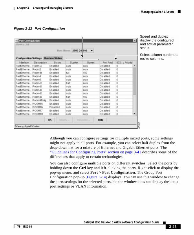
Chapter 3 Creating and Managing ClustersManaging Switch Clusters
Figure 3-13 Port Configuration
Although you can configure settings for multiple mixed ports, some settingsmight not apply to all ports. For example, you can select half duplex from thedrop-down list for a mixture of Ethernet and Gigabit Ethernet ports. The“Guidelines for Configuring Ports” section on page 3-41 describes some of thedifferences that apply to certain technologies.
You can also configure multiple ports on different switches. Select the ports byholding down the Ctrl key and left-clicking the ports. Right-click to display thepop-up menu, and select Port > Port Configuration. The Group PortConfiguration pop-up (Figure 3-14) displays. You can use this window to changethe ports settings for the selected ports, but the window does not display the actualport settings or VLAN information.
4793
2
Select column borders to resize columns.
Speed and duplex display the configured and actual parameter status.
3-43Catalyst 2950 Desktop Switch Software Configuration Guide
78-11380-01

Chapter 3 Creating and Managing ClustersManaging Switch Clusters
Figure 3-14 Group Port Configuration Pop-up
4523
6
Parameters that do not apply to a port are grayed out.
3-44Catalyst 2950 Desktop Switch Software Configuration Guide
78-11380-01

Chapter 3 Creating and Managing ClustersManaging Switch Clusters
To enter a description for a port, select a row, and click Describe. The Basic PortDescription window (Figure 3-15) appears. Enter a description, and click OK. Toenter a description for more than one port, select the rows, and click Describe.Enter a description in the Advanced Port Description window (Figure 3-16), andclick OK.
Figure 3-15 Basic Port Description
Figure 3-16 Advanced Port Description
3-45Catalyst 2950 Desktop Switch Software Configuration Guide
78-11380-01

Chapter 3 Creating and Managing ClustersManaging Switch Clusters
Port Statistics
To display detailed port statistics, click the switch, and select Port > PortStatistics from the Menu bar. The Port Statistics window (Figure 3-17) appears.The Port Statistics window displays detailed port statistics on link performance,dropped packages, total errors, etc.
Figure 3-17 Port Statistics
3-46Catalyst 2950 Desktop Switch Software Configuration Guide
78-11380-01
Chapter 3 Creating and Managing ClustersManaging Switch Clusters
Port Search
To search for a port or a group of ports, click the switch, and select Port > PortSearch from the Menu bar. The Port Search window (Figure 3-18) appears. Entera description in the Find Port(s) with Description field, and click Search. Thesearch results display all the ports that match the description.
3-47Catalyst 2950 Desktop Switch Software Configuration Guide
78-11380-01

Chapter 3 Creating and Managing ClustersManaging Switch Clusters
Figure 3-18 Port Search
3-48Catalyst 2950 Desktop Switch Software Configuration Guide
78-11380-01
Chapter 3 Creating and Managing ClustersManaging Switch Clusters
CLI: Setting Speed and Duplex Parameters
Beginning in privileged EXEC mode, follow these steps to set the speed andduplex parameters on a port:
The “Finding More Information About IOS Commands” section on page 4-1contains the path to the complete IOS documentation.
CLI: Configuring Flow Control on Gigabit Ethernet Ports
The meaning of this parameter is described in Table 3-1 on page 3-38.
Command Purpose
Step 1 configure terminal Enter global configuration mode.
Step 2 interface interface Enter interface configuration mode, andenter the port to be configured.
Step 3 speed {10 | 100 | 1000 | auto} Enter the speed parameter for the port.
Step 4 duplex {full | half | auto} Enter the duplex parameter for the port.
Note The Gigabit Ethernet ports canoperate in either half- orfull-duplex mode when they areset to 10 or 100 Mbps, but whenthey are set to 1000 Mbps theycan only operate in full-duplexmode.
Step 5 end Return to privileged EXEC mode.
Step 6 show running-config Verify your entries.
Step 7 copy running-configstartup-config
(Optional) Save your entry in theconfiguration file. This retains theconfiguration when the switch restarts.
3-49Catalyst 2950 Desktop Switch Software Configuration Guide
78-11380-01

Chapter 3 Creating and Managing ClustersManaging Switch Clusters
Beginning in privileged EXEC mode, follow these steps to configure flow controlon a Gigabit Ethernet port.
The “Finding More Information About IOS Commands” section on page 4-1contains the path to the complete IOS documentation.
Displaying VLAN MembershipThe VLAN Membership window (Figure 3-19) displays the list of all theuser-defined VLANs on the switch. By selecting a VLAN, you can display inCluster Manager the ports that belong to that VLAN. You can also use thiswindow to configure VLANs and trunks, as described in Chapter 5, “Creating andMaintaining VLANs.”
To display the VLANs that are active on a switch, right-click the switch chassisin Cluster Manager, and select VLAN > VLAN Membership from the menu bar.
To display the ports that belong to a given VLAN, select the Display PortMembers tab. Select the VLAN ID, and click Highlight Port Members onDevice. Cluster Manager highlights all the switch ports that belong to that VLAN.The legend on the page describes the meaning of each color.
Command Purpose
Step 1 configure terminal Enter global configuration mode.
Step 2 interface interface Enter interface configuration mode, andenter the port to be configured.
Step 3 flowcontrol [asymmetric |symmetric]
Configure flow control for the port.
Step 4 end Return to privileged EXEC mode.
Step 5 show running-config Verify your entries.
Step 6 copy running-configstartup-config
(Optional) Save your entry in theconfiguration file. This retains theconfiguration when the switch restarts.
3-50Catalyst 2950 Desktop Switch Software Configuration Guide
78-11380-01
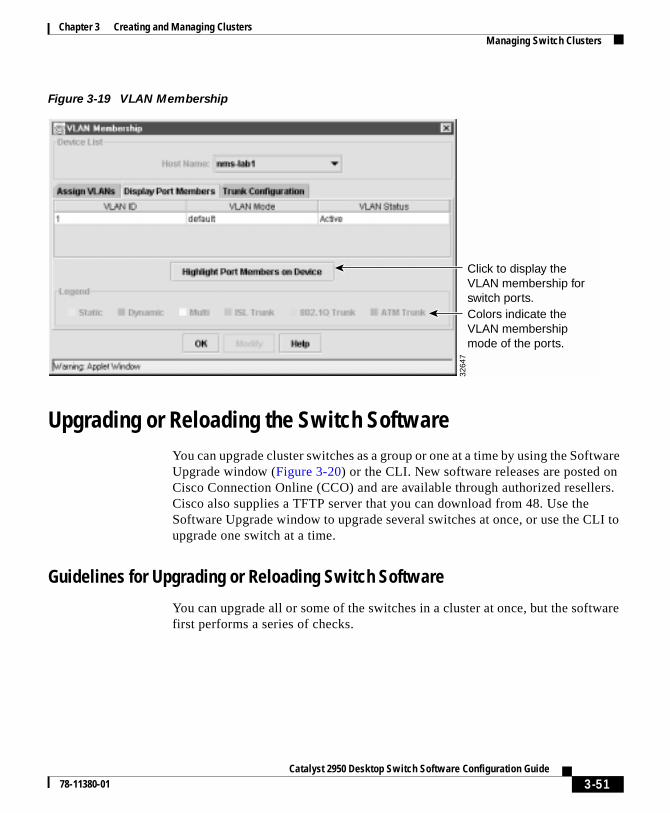
Chapter 3 Creating and Managing ClustersManaging Switch Clusters
Figure 3-19 VLAN Membership
Upgrading or Reloading the Switch SoftwareYou can upgrade cluster switches as a group or one at a time by using the SoftwareUpgrade window (Figure 3-20) or the CLI. New software releases are posted onCisco Connection Online (CCO) and are available through authorized resellers.Cisco also supplies a TFTP server that you can download from 48. Use theSoftware Upgrade window to upgrade several switches at once, or use the CLI toupgrade one switch at a time.
Guidelines for Upgrading or Reloading Switch Software
You can upgrade all or some of the switches in a cluster at once, but the softwarefirst performs a series of checks.
Colors indicate the VLAN membership mode of the ports.
3264
7
Click to display the VLAN membership for switch ports.
3-51Catalyst 2950 Desktop Switch Software Configuration Guide
78-11380-01

Chapter 3 Creating and Managing ClustersManaging Switch Clusters
Configuring the Cisco TFTP Server to Upgrade Multiple Switches
The Cisco TFTP server application can handle multiple requests and sessions, butyou must first disable the TFTP Show File Transfer Progress and the EnableLogging options to avoid TFTP server failures. If you are performingmultiple-switch upgrades with a different TFTP server, it must be capable ofmanaging multiple requests and sessions at the same time.
CLI: Copying the Startup Configuration from the Switch to a PC or Server
When you make changes to a switch configuration, your changes become part ofthe running configuration. When you enter the command to save those changes tothe startup configuration, the switch copies the configuration to the config.text filein Flash memory.
To ensure that you can recreate the configuration if a switch fails, you might wantto copy the config.text file from the switch to a PC or server. The followingprocedure requires a configured TFTP server such as the Cisco TFTP serveravailable on CCO.
Beginning in privileged EXEC mode, enter the following commands to copy aswitch configuration file to the PC or server that has the TFTP server.
The “Finding More Information About IOS Commands” section on page 4-1contains the path to the complete IOS documentation.
Command Purpose
Step 1 copy flash:config.text tftp Copy the file in Flash memory to the rootdirectory of the TFTP server.
Step 2 Address or name of remotehost? ip_address
Follow the prompt for the IP address of thedevice where the TFTP server resides.
Step 3 Destination filename[config.text]? yes/no
Enter the name of the destination file. Thiscould still be config.text.
Step 4 Verify the copy by displaying the contentsof the root directory on the PC or server.
3-52Catalyst 2950 Desktop Switch Software Configuration Guide
78-11380-01
Chapter 3 Creating and Managing ClustersManaging Switch Clusters
Using the Software Upgrade Page to Upgrade Switch Software
In Cluster Manager, select System > Software Upgrade to display the SoftwareUpgrade window (Figure 3-20). Enter the tar filename that contains the switchsoftware image and the web-management code. You can enter just the filename ora path into the New Image File Name field. You do not need to enter a path if theimage file is in directory you have defined as the TFTP root directory.
On Catalyst 2950 switches, new images are copied to Flash memory and do notaffect the operation of the switch. The switch checks Flash memory to ensure thatthere is sufficient space before the upgrade takes place. If there is not enoughspace in Flash memory for the new and old images, the old image is deleted, andthe new image is downloaded. If there is enough space, the new image is copiedto the switch without replacing the old image, and after the new image iscompletely downloaded, the old one is erased. In this case, you can still rebootyour switch using the old image if a failure occurs during the copy process.
New features provided by the software are not available until you reload thesoftware.
3-53Catalyst 2950 Desktop Switch Software Configuration Guide
78-11380-01

Chapter 3 Creating and Managing ClustersManaging Switch Clusters
Figure 3-20 Cluster Software Upgrade
2950, 2900 XL, and 3500 XL switches must be upgraded separately. You can upgrade 1900 and 2820 switches together.
4718
9
Shows upgrade status and which switches failed to upgrade successfully.
Path of upgrade file relative to TFTP server.
Files are renamed on the 2950, 2900 XL, and 3500 XL unless you click here.
Click to reboot all the switches in the cluster.
Click to start upgrade.
IP address of device running the TFTP server.
3-54Catalyst 2950 Desktop Switch Software Configuration Guide
78-11380-01

Chapter 3 Creating and Managing ClustersManaging Switch Clusters
CLI: Upgrading a Standalone Switch
To upgrade a standalone switch, log into the switch by using Telnet, or connect toconsole port on the back of the switch.
The upgrade procedure consists of these steps:
• Changing the name of the current image file to the name of the new file youare copying and replacing the old image file with the new one by using thetar command.
• Disabling access to the HTML pages and deleting the existing HTML filesbefore you upgrade the software to avoid a conflict with users accessing theweb pages during the software upgrade.
• Reenabling access to the HTML pages after the upgrade is complete.
Beginning in privileged EXEC mode, follow these steps to upgrade the switchsoftware:
Command Purpose
Step 1 show version Verify that your switch has 16 MB ofDRAM.
For example, check the line cisco
WS-C2950C (RC32300) processor with
1638K bytes of memory
Step 2 show boot Display the name of the current (default)image file.
Step 3 rename flash:current_imageflash:new_image.bin
Rename the current image file to the nameof the file that you downloaded, and replacethe tar extension with bin. This step doesnot affect the operation of the switch.
Step 4 dir flash: Display the contents of Flash memory toverify the renaming of the file.
Step 5 configure terminal Enter global configuration mode.
Step 6 no IP http server Disable access to the switch HTML pages.
Step 7 end Return to privileged EXEC mode.
3-55Catalyst 2950 Desktop Switch Software Configuration Guide
78-11380-01

Chapter 3 Creating and Managing ClustersManaging Switch Clusters
The “Finding More Information About IOS Commands” section on page 4-1contains the path to the complete IOS documentation.
Step 8 delete flash:html/* Remove the HTML files.
Press Enter to confirm the deletion of eachfile. Do not press any other keys during thisprocess.
Step 9 delete flash:html/Snmp/* For IOS release 11.2(8)SA5 and earlierrunning on 2900 XL switches, remove thefiles in the Snmp directory.
Make sure the S in Snmp is uppercase.
Press Enter to confirm the deletion of eachfile. Do not press any other keys during thisprocess.
Step 10 tar /xtftp://server_ip_address//path/filename.tar flash:
Use the tar command to copy the files intothe switch Flash memory.
Depending on the TFTP server, you mightneed to enter only one slash (/) after theserver_ip_address in the tar command.
Step 11 configure terminal Enter global configuration mode.
Step 12 ip http server Reenable access to the switch HTTP pages.
Step 13 end Return to privileged EXEC mode.
Step 14 reload Reload the new software.
Command Purpose
3-56Catalyst 2950 Desktop Switch Software Configuration Guide
78-11380-01

Chapter 3 Creating and Managing ClustersManaging Switch Clusters
CLI: Reloading or Upgrading Catalyst 2950, 2900 XL, or 3500 XL Member Switches
Because a member switch might not be assigned an IP address, command-linesoftware upgrades through TFTP are managed through the command switch.Follow these steps to reload or upgrade the software on a Catalyst 2950, 2900 XL,or 3500 XL member switch:
Step 1 In privileged EXEC mode on the command switch, display information about thecluster members:
switch# show cluster members
From the display, get the number of the member switch that needs to be upgraded.The member number is listed in the SN column of the display. You need themember number for Step 2.
Step 2 Log into the member switch (for example, member number 1):
switch# rcommand 1
Step 3 Start the TFTP copy as if you were initiating it from the command switch.
switch-1# tar /x tftp://server_ip_address//path/filename.tar flash:Source IP address or hostname [server_ip_address]?Source filename [path/filename]?Destination filename [flash:new_image]?Loading /path/filename.bin from server_ip_address (via!)[OK - 843975 bytes]
Step 4 Reload the new software with the following command:
switch-1# reloadSystem configuration has been modified. Save? [yes/no]:yProceed with reload? [confirm]
Press Enter to start the download.
You lose contact with the switch while it reloads the software. For moreinformation on the rcommand, see the “Understanding the CLI” section onpage 2-25.
3-57Catalyst 2950 Desktop Switch Software Configuration Guide
78-11380-01

Chapter 3 Creating and Managing ClustersManaging Switch Clusters
CLI: Upgrading Catalyst 1900 or 2820 Member Switches
Because a member switch might not be assigned an IP address, command-linesoftware upgrades through TFTP are managed through the command switch.Follow these steps to upgrade the software on a Catalyst 1900 or 2820 memberswitch:
Step 1 In privileged EXEC mode on the command switch, display information about thecluster members:
switch# show cluster members
From the display, get the number of the member switch that needs to be upgraded.The member number is listed in the SN column of the display. You need themember number for Step 2.
Step 2 Log into the member switch (for example, member number 1):
switch# rcommand 1
Step 3 For switches running standard edition software, enter the password (if prompted),access the Firmware Configuration menu from the menu console, and perform theupgrade.
The Telnet session accesses the menu console (the menu-driven interface) if thecommand switch is at privilege level 15. If the command switch is at privilegelevel 1, you are prompted for the password before accessing the menu console.
Follow the instructions in the installation and configuration guide that shippedwith your switch. When the download is complete, the switch resets and beginsusing the new software.
Step 4 For switches running Enterprise Edition Software, start the TFTP copy as if youwere initiating it from the member switch:
switch-1# copy tftp://host/src_file opcode
For example, copy tftp://spaniel/op.bin opcode downloads new systemoperational code op.bin from the host spaniel.
You should see the TFTP successfully downloaded operational code message.When the download is complete, the switch resets and begins using the newsoftware.
3-58Catalyst 2950 Desktop Switch Software Configuration Guide
78-11380-01

Chapter 3 Creating and Managing ClustersManaging Switch Clusters
You can also perform the upgrade through the menu console FirmwareConfiguration menu. For more information, refer to the switch installation andconfiguration guide.
You lose contact with the switch while it reloads the software. For moreinformation on the rcommand, see the “Understanding the CLI” section onpage 2-25.
Reloading Switch Software
When you upgrade a switch, the switch continues to operate normally while thenew software is copied to Flash memory. If Flash memory does not have enoughspace for two images, the new image is copied over the existing one. If Flashmemory has enough space, the new image is copied to the selected switch but doesnot replace the current running image. Only after the new image is completelydownloaded is the old one erased. If you experience a failure during the copyprocess, you can still reboot your switch by using the old image. The new softwareis loaded the next time you reboot.
If you group switches into a cluster, you can upgrade the entire cluster fromCluster Manager. For more information, see the “Upgrading or Reloading theSwitch Software” section on page 3-51.
Configuring SNMP for a ClusterThe command switch manages SNMP communication for all switches in thecluster. The command switch forwards the set and get requests from SNMPapplications to member switches, and it forwards the traps and other responsescoming from the member switches to the appropriate management station. SNMPmust be enabled for the Cluster Management features to work properly.
Note This section describes how the clustering software interacts with SNMP whena cluster is created. For more information on configuring SNMP, see the“Configuring SNMP” section on page 4-41.
3-59Catalyst 2950 Desktop Switch Software Configuration Guide
78-11380-01

Chapter 3 Creating and Managing ClustersManaging Switch Clusters
Enabling or Disabling the SNMP Agent
You can enable or disable the SNMP agent on your cluster switches. By default,the SNMP agent is enabled on the Catalyst 1900, 2820, Catalyst 2950, 2900 XL,and 3500 XL switches. You cannot disable the agent on Catalyst 1900 and 2820switches.
Note SNMP must be enabled for the CMS graphing features.
Configuring Community Strings for Cluster Switches
Use the SNMP Manager window (Figure 3-21 and Figure 3-22) to enterread-write and read-only community strings on individual cluster switches.Community strings provide authentication in the exchange of SNMP messages.
Catalyst 2950, 2900 XL, and 3500 XL switches support an unlimited number ofcommunity strings of any length. When you configure a community string forthese switches using SNMP Manager, do not use the @esN notation (N is themember-switch number) because this information is automatically appended toeach string.
When a switch is removed from the cluster, community strings ending in @esNare removed. If the switch rejoins a cluster at a later time, the first read-only andread-write community strings from the command switch are appended with an@esN and propagated to the member switch.
The Catalyst 1900 and 2820 switches support up to four read-only and fourread-write community strings that are 32 characters in length. Because aread-only and read-write community string from the command switch waspropagated to the switch when it joined the cluster, you can configure up to threeadditional read-only and three read-write community strings. When you configurecommunity strings for these switches through the SNMP Manager window, limitthe string length to 27 characters because the @esN, where N can be up to twodigits, is automatically appended to each string. Do not use the @esN notation inany community string you configure. If you enter a string longer than 27characters, it is truncated to 27.
When removing community strings from cluster members, make sure not toremove the community strings propagated from the command switch when theswitch joined the cluster. If you remove the propagated community string, thecommand switch cannot route SNMP packets to the member switch.
3-60Catalyst 2950 Desktop Switch Software Configuration Guide
78-11380-01

Chapter 3 Creating and Managing ClustersManaging Switch Clusters
On Catalyst 2950, 2900 XL, and 3500 XL switches, the first read-only andread-write community string listed in the SNMP Manager window is propagatedfrom the command switch. On Catalyst 1900 and 2820 switches, the last read-onlyand last read-write community string listed in the SNMP Manager window ispropagated from the command switch.
Figure 3-21 SNMP Manager for Catalyst 2950 Switches
4720
2
Enter a character stringto act as a password for the trap manager.
Catalyst 2900, 2950, and 3500 traps.
You cannot disable the SNMP agent on Catalyst 1900 and 2820 switches.
Enter the IP address ofPC or workstation to receive traps.
3-61Catalyst 2950 Desktop Switch Software Configuration Guide
78-11380-01

Chapter 3 Creating and Managing ClustersManaging Switch Clusters
Figure 3-22 SNMP Manager for Catalyst 1900 and 2820 Switches
Enter a character stringto act as a password for the trap manager.
Catalyst 1900 and 2820 traps.
You cannot disable the SNMP agent on Catalyst 1900 and 2820 switches.
Enter the IP address ofPC or workstation to receive traps.
4872
1
1900-1
3-62Catalyst 2950 Desktop Switch Software Configuration Guide
78-11380-01

Chapter 3 Creating and Managing ClustersManaging Switch Clusters
Configuring Trap Managers and Enabling Traps
A trap manager is a management station that receives and processes traps. Trapsare system alerts that the switch generates when certain events occur. If themember switch does not have an IP address, communication between the SNMPmanagement station and the switch is managed by the command switch.
The command switch does not propagate its trap manager addresses or trapcommunity strings to cluster members. By default, no trap manager is defined,and no traps are issued.
Catalyst 2950, 2900 XL, and 3500 XL switches support an unlimited number oftrap managers. Community strings can be any length. When you configure acommunity string for these switches, do not use the @esN notation because thisinformation is automatically appended to each string by the command switch.
Table 3-2 describes the Catalyst 2950, 2900 XL, and 3500 XL switch traps. Youcan enable any or all of these traps and configure a trap manager to receive them.
Catalyst 1900 and 2820 switches support up to four trap managers. When youconfigure community strings for these switches, limit the string length to32 characters. When configuring traps on Catalyst 1900 and 2820 switches, youcannot configure individual trap managers to receive specific traps.
Table 3-3 describes the Catalyst 1900 and 2820 switch traps. You can enable anyor all of these traps, but these traps are received by all configured trap managers.
Table 3-2 2950, 2900 XL, and 3500 XL Switch Traps
Trap Type Description
Config Generates a trap when the switch configuration changes.
TTY Generates a trap when the switch starts a management consoleCLI session.
VTP Generates a trap for VLAN Trunk Protocol (VTP) changes.
SNMP Generates the supported SNMP traps.
VLANMembership
Generates a trap for each VLAN Membership Policy Server(VMPS).
C2900/C3500 Generates the switch-specific traps. These traps are in theprivate enterprise-specific Management Information Base(MIB).
3-63Catalyst 2950 Desktop Switch Software Configuration Guide
78-11380-01

Chapter 3 Creating and Managing ClustersManaging Switch Clusters
Table 3-3 Catalyst 1900 and 2820 Switch Traps
Trap Type Description
Address-violation Generates a trap when the address violation threshold isexceeded.
Authentication Generates a trap when an SNMP request is notaccompanied by a valid community string.
BSC Generates a trap when the broadcast threshold is exceeded.
Link-up-down Generates a link-down trap when a port is suspended ordisabled for any of these reasons:
• Secure address violation (address mismatch orduplication)
• Network connection error (loss of linkbeat or jabbererror)
User disabling the port
Generates a link-up trap when a port is enabled for any ofthese reasons:
• Presence of linkbeat
• Management intervention
• Recovery from an address violation or any other error
• STP action
VTP Generates a trap when VTP changes occur.
3-64Catalyst 2950 Desktop Switch Software Configuration Guide
78-11380-01

Catalyst 2950 Desktop Swi78-11380-01
C H A P T E R 4
Managing SwitchesThis chapter describes how to use the device-management features of the ClusterManagement Suite (CMS). The features described in this chapter can all beimplemented through Visual Switch Manager (VSM), the web-based interface formanaging standalone switches, or through Cluster Manager. If you needinformation on how to group your switches into a cluster, see Chapter 3, “Creatingand Managing Clusters.”
This chapter describes two ways to configure switches:
• By using CMS windows to monitor and configure switches and ports.
How-to procedures for using the windows are in the online help.
• By using the Cisco IOS command-line interface (CLI).
CLI procedures are included for many tasks in this chapter. There are somefeatures that can only be implemented by using the CLI.
Finding More Information About IOS CommandsThis guide describes only the IOS commands that have been created orchanged for the Catalyst 2950 switches. These commands are furtherdescribed in the Catalyst 2950 Desktop Switch Command Reference.
For information on other IOS Release 12.0 commands, refer to the Cisco IOSRelease 12.0 documentation set available on Cisco.com.
4-1tch Software Configuration Guide

Chapter 4 Managing SwitchesManaging Configuration Conflicts
Managing Configuration ConflictsCertain combinations of port features create configuration conflicts (seeTable 4-1). If you try to enable incompatible features, CMS issues a warningmessage, and you cannot make the change. Reload the page to refresh CMS.
In Table 4-1, No means that the two referenced features are incompatible andshould not both be enabled; yes means that both can be enabled at the same timeand will not cause an incompatibility conflict.
Features, Default Settings, and DescriptionsYou can configure the software features of this release by using any of theavailable interfaces. Table 4-2 lists the most important features, their defaults, andwhere they are described in this guide.
Table 4-1 Conflicting Features
Protected Port
Port Group
Port Security
SPAN Port
Connect to Cluster?
Protected Port – Yes Yes No Yes
Port Group Yes – No No Yes
Port Security Yes No – No Yes
SPAN Port No No No – Yes
Connect to Cluster Yes Yes Yes Yes –
4-2Catalyst 2950 Desktop Switch Software Configuration Guide
78-11380-01

Chapter 4 Managing SwitchesFeatures, Default Settings, and Descriptions
Table 4-2 Default Settings and Where To Change Them
FeatureDefault Setting
Location of Feature and Feature Description
Equivalent IOS CLI Procedure
Network Management
Creating clusters None Cluster Builder
“Creating Clusters” section on page 3-5
“CLI: Creating a Cluster”section on page 3-8
Removing clustermembers
None Cluster Builder
“Adding and Removing MemberSwitches” section on page 3-12
“CLI: Removing aMember from a Cluster”section on page 3-16
Reloading orUpgrading clustersoftware
Enabled Cluster Manager: System > SoftwareUpgrade
“Upgrading or Reloading the SwitchSoftware” section on page 3-51
“Upgrading or Reloadingthe Switch Software”section on page 3-51
Displaying graphs Enabled Cluster Manager and Cluster Builder
“Displaying Link Graphs” section onpage 6-1
–
ConfiguringSNMP communitystrings and trapmanagers
None Cluster Manager: System > SNMPManagement
“Configuring SNMP” section onpage 4-41
–
Configuring a port None Cluster Manager
“Monitoring and Configuring Ports”section on page 3-38
“Configuring Ports”section on page 3-42
4-3Catalyst 2950 Desktop Switch Software Configuration Guide
78-11380-01

Chapter 4 Managing SwitchesFeatures, Default Settings, and Descriptions
Device Management
Switch IP address,subnet mask, anddefault gateway
0.0.0.0 Cluster Manager: System > IPManagement
“Configuring IP Information” section onpage 4-26
“CLI: Assigning IPInformation to the Switch”section on page 4-28
Dynamic HostConfigurationProtocol (DHCP)
DHCPclientenabled
“DHCP-Based Autoconfiguration”section on page 4-29
–
ManagementVLAN
VLAN 1 Cluster Manager: Cluster > ManagementVLAN
“Changing the Management VLAN”section on page 3-34
“Changing theManagement VLAN”section on page 3-34
Domain name None Cluster Manager: System > IPManagement
“Specifying a Domain Name andConfiguring the DNS” section onpage 4-39
Documentation set forCisco IOS Release 12.0 onCisco.com
Cisco DiscoveryProtocol (CDP)
Enabled – Documentation set forCisco IOS Release 12.0 onCisco.com
CoS and WRR Disabled Cluster Manager: Device > CoS andWRR
“CoS and WRR” section on page 5-39
“CLI: Configuring CoSPriority Queues” sectionon page 5-42
“CLI: Configuring WRR”section on page 5-43
AddressResolutionProtocol (ARP)
Enabled Cluster Manager: System > ARP Table
“Managing the ARP Table” section onpage 4-47
Documentation set forCisco IOS Release 12.0 onCisco.com
Table 4-2 Default Settings and Where To Change Them (continued)
FeatureDefault Setting
Location of Feature and Feature Description
Equivalent IOS CLI Procedure
4-4Catalyst 2950 Desktop Switch Software Configuration Guide
78-11380-01

Chapter 4 Managing SwitchesFeatures, Default Settings, and Descriptions
System TimeManagement
None Cluster Manager: Cluster > System TimeManagement
“Setting the System Date and Time”section on page 4-22
Documentation set forCisco IOS Release 12.0 onCisco.com
Static addressassignment
Noneassigned
Cluster Manager: Security > AddressManagement
“Adding and Removing StaticAddresses” section on page 4-55
“CLI: Adding StaticAddresses” section onpage 4-57
Dynamic addressmanagement
Enabled Cluster Manager: Security > AddressManagement
“Managing the MAC Address Tables”section on page 4-49 and “Changing theAddress Aging Time” section onpage 4-50
“CLI: Configuring theAging Time” section onpage 4-51
“CLI: Removing DynamicAddress Entries” sectionon page 4-52
VLANmembership
Static-accessports inVLAN 1
Cluster Manager: VLAN > VLANMembership
“Displaying VLAN Membership”section on page 3-50
“Assigning Static-Access Ports to aVLAN” section on page 5-5
“CLI: Configuring a Trunk Port” sectionon page 5-32
“CLI: AssigningStatic-Access Ports to aVLAN” section onpage 5-28
“CLI: Configuring a TrunkPort” section on page 5-32
VTP Management VTPservermode
Cluster Manager: VLAN > VTPManagement
“Configuring VTP” section on page 5-12
“CLI: Configuring VTPServer Mode” section onpage 5-14
Table 4-2 Default Settings and Where To Change Them (continued)
FeatureDefault Setting
Location of Feature and Feature Description
Equivalent IOS CLI Procedure
4-5Catalyst 2950 Desktop Switch Software Configuration Guide
78-11380-01

Chapter 4 Managing SwitchesFeatures, Default Settings, and Descriptions
Performance
Autonegotiationof duplex modeand port speeds
Enabled Cluster Manager: Port > PortConfiguration
“Monitoring and Configuring Ports”section on page 3-38
“CLI: Setting Speed andDuplex Parameters”section on page 3-49
Gigabit Ethernetflow control
Any Cluster Manager > Port Configuration
Configuring Ports, page 3-42
CLI: Configuring FlowControl on GigabitEthernet Ports, page 3-49
Flooding Control
Storm control Disabled Cluster Manager: Port > FloodingControl
“Configuring Flooding Controls” sectionon page 4-18
“CLI: Enabling StormControl” section onpage 4-20
IGMP Snooping Enabled Cluster Manager: Device > IGMPSnooping
“IGMP Snooping” section on page 4-64
“CLI: Enabling orDisabling IGMPSnooping” section onpage 4-67
“CLI: Enabling IGMPImmediate-LeaveProcessing” section onpage 4-68
“CLI: Configuring aMulticast Router Port”section on page 4-79
Table 4-2 Default Settings and Where To Change Them (continued)
FeatureDefault Setting
Location of Feature and Feature Description
Equivalent IOS CLI Procedure
4-6Catalyst 2950 Desktop Switch Software Configuration Guide
78-11380-01

Chapter 4 Managing SwitchesFeatures, Default Settings, and Descriptions
Network Redundancy
Hot StandbyRouter Protocol
Disabled “Building a Redundant Cluster” sectionon page 3-17
“CLI: Creating a StandbyGroup” section onpage 3-22
“CLI: Adding MemberSwitches to a StandbyGroup” section onpage 3-24
“CLI: Removing a Switchfrom a Standby Group”section on page 3-25
Spanning TreeProtocol
Enabled Cluster Manager: Device > SpanningTree Protocol
“Configuring the Spanning TreeProtocol” section on page 4-80
“CLI: Disabling STP”section on page 4-84
“CLI: Changing the PathCost” section on page 4-97
“CLI: Changing the PortPriority” section onpage 4-98
“CLI: Enabling STP PortFast” section on page 4-97
“CLI: Configuring STPRoot Guard” section onpage 4-98
Unidirectionallink detection
Disabled – “CLI: ConfiguringUniDirectional LinkDetection” section onpage 4-100
Port grouping Noneassigned
Cluster Manager: Port > Port Grouping(EC)
“Creating EtherChannel Port Groups”section on page 4-11
“CLI: CreatingEtherChannel PortGroups” section onpage 4-15
Table 4-2 Default Settings and Where To Change Them (continued)
FeatureDefault Setting
Location of Feature and Feature Description
Equivalent IOS CLI Procedure
4-7Catalyst 2950 Desktop Switch Software Configuration Guide
78-11380-01
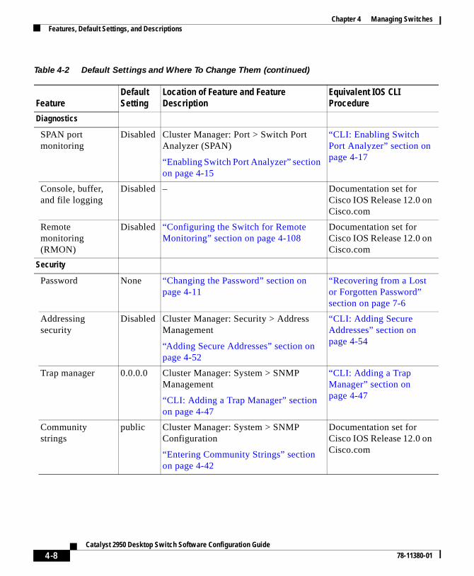
Chapter 4 Managing SwitchesFeatures, Default Settings, and Descriptions
Diagnostics
SPAN portmonitoring
Disabled Cluster Manager: Port > Switch PortAnalyzer (SPAN)
“Enabling Switch Port Analyzer” sectionon page 4-15
“CLI: Enabling SwitchPort Analyzer” section onpage 4-17
Console, buffer,and file logging
Disabled – Documentation set forCisco IOS Release 12.0 onCisco.com
Remotemonitoring(RMON)
Disabled “Configuring the Switch for RemoteMonitoring” section on page 4-108
Documentation set forCisco IOS Release 12.0 onCisco.com
Security
Password None “Changing the Password” section onpage 4-11
“Recovering from a Lostor Forgotten Password”section on page 7-6
Addressingsecurity
Disabled Cluster Manager: Security > AddressManagement
“Adding Secure Addresses” section onpage 4-52
“CLI: Adding SecureAddresses” section onpage 4-54
Trap manager 0.0.0.0 Cluster Manager: System > SNMPManagement
“CLI: Adding a Trap Manager” sectionon page 4-47
“CLI: Adding a TrapManager” section onpage 4-47
Communitystrings
public Cluster Manager: System > SNMPConfiguration
“Entering Community Strings” sectionon page 4-42
Documentation set forCisco IOS Release 12.0 onCisco.com
Table 4-2 Default Settings and Where To Change Them (continued)
FeatureDefault Setting
Location of Feature and Feature Description
Equivalent IOS CLI Procedure
4-8Catalyst 2950 Desktop Switch Software Configuration Guide
78-11380-01

Chapter 4 Managing SwitchesConfiguring Standalone Switches
Configuring Standalone SwitchesVisual Switch Manager (VSM) is one of the CMS interfaces for managingindividual switch features. If you are configuring a standalone switch, you canaccess VSM directly by entering the switch IP address in the browser Locationfield (Netscape Communicator) or Address field (Internet Explorer). ClickCluster Management Suite or Visual Switch Manager on the Cisco SystemsAccess Page, and the switch senses that the IP address refers to a standaloneswitch and displays the VSM home page.
Note Menu options are arranged slightly differently in VSM than in ClusterManager. For the complete list of the options available, see “VSM Menu BarOptions” section on page 2-22.
A browser plug-in is required to access the HTML interface. For information oninstalling the plug-in, refer to the Release Notes for the Catalyst 2950 Cisco IOSRelease 12.0(5)WC(1).
Port security Disabled Cluster Manager: Security > PortSecurity
“Enabling Port Security” section onpage 4-58
“CLI: Enabling PortSecurity” section onpage 4-61
TACACS+ Disabled “Configuring TACACS+” section onpage 4-101
“CLI Procedures forConfiguring TACACS+”section on page 4-102
Protected Port Disabled “Configuring Protected Ports” section onpage 4-100
“Configuring ProtectedPorts” section onpage 4-100
Table 4-2 Default Settings and Where To Change Them (continued)
FeatureDefault Setting
Location of Feature and Feature Description
Equivalent IOS CLI Procedure
4-9Catalyst 2950 Desktop Switch Software Configuration Guide
78-11380-01

Chapter 4 Managing SwitchesEnabling the Switch as a Command Switch
Figure 4-1 VSM Home Page
Enabling the Switch as a Command SwitchBefore you can create a cluster, one switch must be assigned an IP address andenabled as the command switch. See the “Command Switch Requirements”section on page 3-3 to ensure that the switch meets all the requirements.
To enable a command switch, select Cluster > Cluster CommandConfiguration from the menu bar, and select Enable on the ClusterConfiguration window. You can use up to 28 characters to name your cluster.After you have enabled the command switch, select Cluster > Cluster Builder tobegin building your cluster. To build your cluster by using the CLI, see the “CLI:Creating a Cluster” section on page 3-8.
4871
6
Right-click a port, and select Port Configuration to enable or disable the port and set the speed, duplex, Port Fast, and other port parameters.
STAT displays the port status, SPD displays the port speed, and FDUP displays the port duplex setting.
Left-click Mode to change the meaning of the port LEDs.
Press Ctrl, and left-click ports to select multiple ports.
4-10Catalyst 2950 Desktop Switch Software Configuration Guide
78-11380-01

Chapter 4 Managing SwitchesChanging the Password
Figure 4-2 Enable Command Switch
Changing the PasswordIf you change the enable secret password, your connection with the switch breaks,and the browser prompts you for the new password. You can only change apassword by using the CLI. If you have forgotten your password, see the“Recovering from a Lost or Forgotten Password” section on page 7-6.
The “Finding More Information About IOS Commands” section on page 4-1contains the path to the complete IOS documentation.
Creating EtherChannel Port GroupsUse the Port Group (EtherChannel) window (Figure 4-4) to create FastEtherChannel and Gigabit EtherChannel port groups. These port groups act assingle logical ports for high-bandwidth connections between switches or betweenswitches and servers.
To display this window, select Port > Port Grouping (EtherChannel) from themenu bar.
For the restrictions that apply to port groups, see the “Managing ConfigurationConflicts” section on page 4-2.
3475
3
4-11Catalyst 2950 Desktop Switch Software Configuration Guide
78-11380-01

Chapter 4 Managing SwitchesCreating EtherChannel Port Groups
Understanding EtherChannel Port GroupingThis software release supports two different types of port groups: source-basedforwarding port groups and destination-based forwarding port groups.
Source-based forwarding port groups distribute packets forwarded to the groupbased on the source address of incoming packets. You can configure up to eightports in a source-based forwarding port group. Source-based forwarding isenabled by default.
Destination-based port groups distribute packets forwarded to the group based onthe destination address of incoming packets. You can configure up to eight portsin a group.
You can create up to 6 port groups of all source-based, all destination-based, or acombination of source- and destination-based ports. All ports in the group mustbe of the same type; for example, they must be all source based or all destinationbased. You can independently configure port groups that link switches, but youmust consistently configure both ends of a port group.
In Figure 4-3, a port group of two workstations communicates with a router.Because the router is a single-MAC address device, source-based forwardingensures that the switch uses all available bandwidth to the router. The router isconfigured for destination-based forwarding because the large number of stationsensures that the traffic is evenly distributed through the port-group ports on therouter.
Figure 4-3 Source-Based Forwarding
The switch treats the port group as a single logical port; therefore, when youcreate a port group, the switch uses the configuration of the first port for all portsadded to the group. If you add a port and change the forwarding method, itchanges the forwarding for all ports in the group. After the group is created,
FEC port group
4495
8
Source-basedforwarding
Destination-basedforwarding
Cisco routerCatalyst 2900 XL,Catalyst 2950 or
Catalyst 3500 XL switch
4-12Catalyst 2950 Desktop Switch Software Configuration Guide
78-11380-01
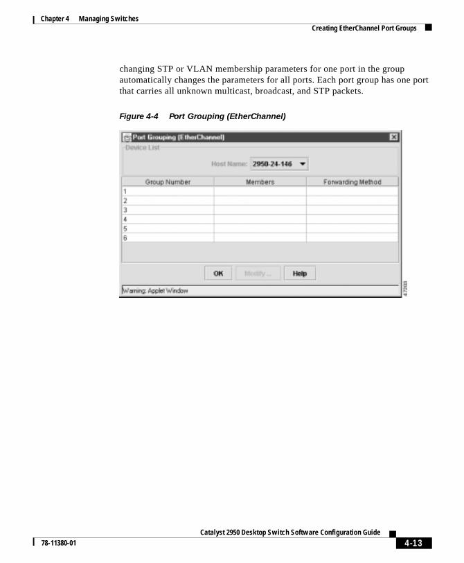
Chapter 4 Managing SwitchesCreating EtherChannel Port Groups
changing STP or VLAN membership parameters for one port in the groupautomatically changes the parameters for all ports. Each port group has one portthat carries all unknown multicast, broadcast, and STP packets.
Figure 4-4 Port Grouping (EtherChannel)
4-13Catalyst 2950 Desktop Switch Software Configuration Guide
78-11380-01

Chapter 4 Managing SwitchesCreating EtherChannel Port Groups
Figure 4-5 Port Group Configuration
Port Group Restrictions on Static-Address ForwardingThe following restrictions apply to entering static addresses that are forwarded toport groups:
• If the port group forwards based on the source MAC address (the default),configure the static address to forward to all ports in the group. This methodeliminates the chance of lost packets.
• If the port group forwards based on the destination address, configure thestatic address to forward to only one port in the port group. This methodavoids the possible transmission of duplicate packets. For more information,see “Adding and Removing Static Addresses” section on page 4-55.
Select Destination-based when connecting to a switch or multi-MAC address device. Select a maximum of 8 ports.
Select Source-based when connecting to a router or other single-MAC address device. Select a maximum of 8 ports.
5466
4
4-14Catalyst 2950 Desktop Switch Software Configuration Guide
78-11380-01

Chapter 4 Managing SwitchesEnabling Switch Port Analyzer
CLI: Creating EtherChannel Port GroupsBeginning in privileged EXEC mode, follow these steps to create a two-portgroup:
The “Finding More Information About IOS Commands” section on page 4-1contains the path to the complete IOS documentation.
Enabling Switch Port AnalyzerYou can monitor traffic on a given port by forwarding incoming and outgoingtraffic on the port to another port in the same VLAN. Use the Switch PortAnalyzer (SPAN) window (Figure 4-6) to enable port monitoring on a port, anduse the Modify the Ports Being Monitored window (Figure 4-7) to select the portto be monitored. A SPAN port cannot monitor ports in a different VLAN, and aSPAN port must be a static-access port. You can have only one assigned monitorport at any given time. If you select another port as the monitor port, the previousmonitor port is disabled, and the newly selected port becomes the monitor port.
Command Purpose
Step 1 configure terminal Enter global configuration mode.
Step 2 interface interface Enter interface configuration mode, andenter the port of the first port to be added tothe group.
Step 3 port group 1 distributiondestination
Assign the port to group 1 withdestination-based forwarding.
Step 4 interface interface Enter the second port to be added to thegroup.
Step 5 port group 1 distributiondestination
Assign the port to group 1 withdestination-based forwarding.
Step 6 end Return to privileged EXEC mode.
Step 7 show running-config Verify your entries.
4-15Catalyst 2950 Desktop Switch Software Configuration Guide
78-11380-01

Chapter 4 Managing SwitchesEnabling Switch Port Analyzer
To display this window, select Port > Switch Port Analyzer from the menu bar.
For the restrictions that apply to SPAN ports, see the “Managing ConfigurationConflicts” section on page 4-2.
Figure 4-6 Switch Port Analyzer (SPAN)
4-16Catalyst 2950 Desktop Switch Software Configuration Guide
78-11380-01

Chapter 4 Managing SwitchesEnabling Switch Port Analyzer
Figure 4-7 Modify the Ports Being Monitored
CLI: Enabling Switch Port AnalyzerBeginning in privileged EXEC mode, follow these steps to enable switch portanalyzer:
The “Finding More Information About IOS Commands” section on page 4-1contains the path to the complete IOS documentation.
2968
6
Monitor ports must be in same VLAN as ports being monitored.
Command Purpose
Step 1 configure terminal Enter global configuration mode.
Step 2 interface interface Enter interface configuration mode, andenter the port that acts as the monitor port.
Step 3 port monitor interface Enable port monitoring on the port.
Step 4 end Return to privileged EXEC mode.
Step 5 show running-config Verify your entries.
4-17Catalyst 2950 Desktop Switch Software Configuration Guide
78-11380-01

Chapter 4 Managing SwitchesConfiguring Flooding Controls
CLI: Disabling Switch Port AnalyzerBeginning in privileged EXEC mode, follow these steps to disable switch portanalyzer:
The “Finding More Information About IOS Commands” section on page 4-1contains the path to the complete IOS documentation.
Configuring Flooding ControlsUse the Flooding Controls window (Figure 4-8) to block the forwarding ofunnecessary flooded traffic.
To display this window, select Port > Flooding Controls from the menu bar.
Enabling Storm ControlA packet storm occurs when a large number of broadcast, unicast, or multicastpackets are received on a port. Forwarding these packets can cause the network toslow down or to time out. Storm control is configured for the switch as a wholebut operates on a per-port basis. By default, storm control is disabled.
Storm control uses high and low thresholds to block and then restore theforwarding of broadcast, unicast, or multicast packets. You can also set the switchto shut down the port when the rising threshold is reached.
Command Purpose
Step 1 configure terminal Enter global configuration mode.
Step 2 interface interface Enter interface configuration mode, andenter the port number of the monitor port.
Step 3 no port monitor interface Disable port monitoring on the port.
Step 4 end Return to privileged EXEC mode.
Step 5 show running-config Verify your entries.
4-18Catalyst 2950 Desktop Switch Software Configuration Guide
78-11380-01

Chapter 4 Managing SwitchesConfiguring Flooding Controls
The rising threshold is the number of packets that a switch port can receive beforeforwarding is blocked. The falling threshold is the number of packets below whichthe switch resumes normal forwarding. In general, the higher the threshold, theless effective the protection against broadcast storms. The maximum half-duplextransmission on a 100BaseT link is 148,000 packets per second, but you can entera threshold of up to 4294967295 broadcast packets per second.
To configure storm control, right-click a switch chassis in Cluster Manager, andselect Port > Flooding Controls. Select one of the Storm tabs (Figure 4-8), selecta port, and click Modify. Set the parameters on the Flooding ControlsConfiguration pop-up (Figure 4-9).
Figure 4-8 Flooding Controls
Number of broadcast packets per second arriving on the port.
Number of traps sent to indicate the start and stop of broadcast storm control.
4720
5
Select column borders to resize a column.
4-19Catalyst 2950 Desktop Switch Software Configuration Guide
78-11380-01
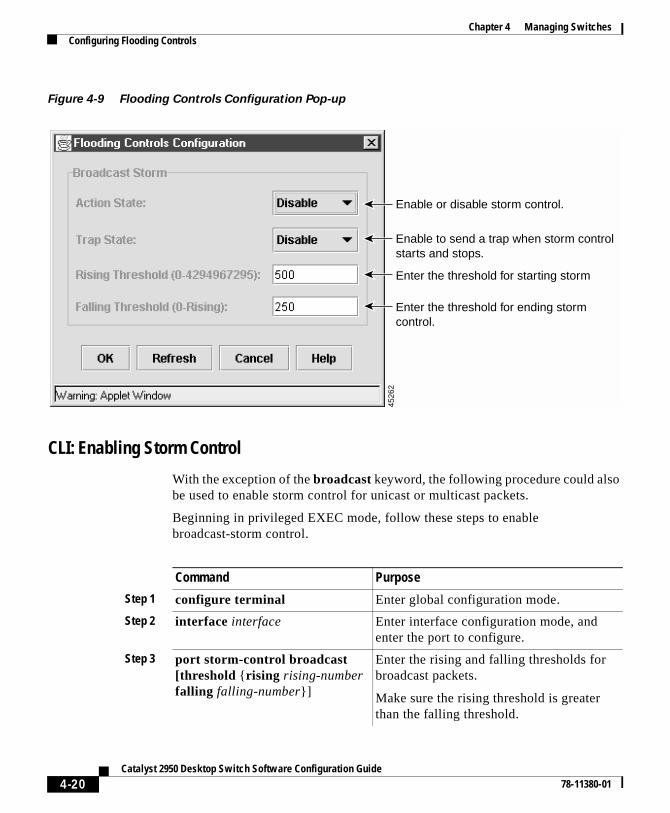
Chapter 4 Managing SwitchesConfiguring Flooding Controls
Figure 4-9 Flooding Controls Configuration Pop-up
CLI: Enabling Storm Control
With the exception of the broadcast keyword, the following procedure could alsobe used to enable storm control for unicast or multicast packets.
Beginning in privileged EXEC mode, follow these steps to enablebroadcast-storm control.
4526
2
Enable or disable storm control.
Enable to send a trap when storm control starts and stops.
Enter the threshold for starting storm
Enter the threshold for ending storm control.
Command Purpose
Step 1 configure terminal Enter global configuration mode.
Step 2 interface interface Enter interface configuration mode, andenter the port to configure.
Step 3 port storm-control broadcast[threshold {rising rising-numberfalling falling-number}]
Enter the rising and falling thresholds forbroadcast packets.
Make sure the rising threshold is greaterthan the falling threshold.
4-20Catalyst 2950 Desktop Switch Software Configuration Guide
78-11380-01

Chapter 4 Managing SwitchesConfiguring Flooding Controls
The “Finding More Information About IOS Commands” section on page 4-1contains the path to the complete IOS documentation.
CLI: Disabling Storm Control
Beginning in privileged EXEC mode, follow these steps to disablebroadcast-storm control.
The “Finding More Information About IOS Commands” section on page 4-1contains the path to the complete IOS documentation.
Step 4 port storm-control trap Generate an SNMP trap when the traffic onthe port crosses the rising or fallingthreshold.
Step 5 end Return to privileged EXEC mode.
Step 6 show port storm-control[interface]
Verify your entries.
Command Purpose
Command Purpose
Step 1 configure terminal Enter global configuration mode.
Step 2 interface interface Enter interface configuration mode, andenter the port to configure.
Step 3 no port storm-control broadcast Disable port storm control.
Step 4 end Return to privileged EXEC mode.
Step 5 show port storm-control[interface]
Verify your entries.
4-21Catalyst 2950 Desktop Switch Software Configuration Guide
78-11380-01

Chapter 4 Managing SwitchesManaging the System Date and Time
Managing the System Date and TimeUse the System Time Management window (Figure 4-10) to set the system timefor a switch or enable an external source such as Network Time Protocol (NTP)to supply time to the switch.
You can use this window to set the switch time by using one of the followingtechniques:
• Manually setting the system time (including daylight saving time) and date
• Configuring the switch to run in NTP client mode and to receive timeinformation from an NTP server
• Configuring the switch to run in NTP broadcast-client mode and to receiveinformation from an NTP broadcast server
To display this window, select Cluster > System Time Management from themenu bar.
Setting the System Date and TimeEnter the date and a 24-hour clock time setting on the System Time Managementwindow. If you are entering the time for an American time zone, enter thethree-letter abbreviation for the time zone in the Name of Time Zone field, suchas PST for Pacific standard time. If you are identifying the time zone by referringto Greenwich mean time, enter UTC (universal coordinated time) in the Name ofTime Zone field. You then must enter a negative or positive number as an offsetto indicate the number of time zones between the switch and Greenwich, England.Enter a negative number if the switch is west of Greenwich, England, and east ofthe international date line. For example, California is eight time zones west ofGreenwich, so you would enter –8 in the Hours Offset From UTC field. Enter apositive number if the switch is east of Greenwich. You can also enter negativeand positive numbers for minutes.
You can also set the date and time by using the CLI. “Finding More InformationAbout IOS Commands” section on page 4-1 contains the path to the complete IOSdocumentation.
4-22Catalyst 2950 Desktop Switch Software Configuration Guide
78-11380-01

Chapter 4 Managing SwitchesManaging the System Date and Time
Figure 4-10 System Time Management
Configuring Daylight Saving TimeTo configure daylight saving time, click the Set Daylight Saving Time tab(Figure 4-11). You can configure the switch to change to daylight saving time ona particular day every year, on a day that you enter, or not at all.
2968
2
Click to configure time from an NTP server. Do not configure NTP if you use the Set Current Time tab.
Set time manually if there is no NTP server.
Set time in relation to Greenwich mean time.
4-23Catalyst 2950 Desktop Switch Software Configuration Guide
78-11380-01

Chapter 4 Managing SwitchesManaging the System Date and Time
Figure 4-11 Set Daylight Savings Time Tab
Configuring the Network Time ProtocolIn complex networks, it is often prudent to distribute time information from acentral server. The NTP can distribute time information by responding to requestsfrom clients or by broadcasting time information. You can use the Network TimeProtocol window (Figure 4-12) to enable these options and to enter authenticationinformation to accompany NTP client requests.
To display this window, click Network Time Protocol on the System TimeManagement window.
You can also configure NTP by using the CLI. “Finding More Information AboutIOS Commands” section on page 4-1 contains the path to the complete IOSdocumentation.
3264
1
4-24Catalyst 2950 Desktop Switch Software Configuration Guide
78-11380-01

Chapter 4 Managing SwitchesManaging the System Date and Time
Figure 4-12 Network Time Protocol
Configuring the Switch as an NTP Client
You configure the switch as an NTP client by entering the IP addresses of up toten NTP servers in the IP Address field. Click Preferred Server to specify whichserver should be used first. You can also enter an authentication key to be used asa password when requests for time information are sent to the server.
4572
2
Configure the NTP server for the switch. Key ID is for authentication.
Enable NTP authentication.
Enable the switch to receive NTP broadcast packets.
Enter a delay in microseconds to allow for the estimated broadcast interval.
4-25Catalyst 2950 Desktop Switch Software Configuration Guide
78-11380-01

Chapter 4 Managing SwitchesConfiguring IP Information
Enabling NTP Authentication
To ensure the validity of information received from NTP servers, you canauthenticate NTP messages with public-key encryption. This procedure must becoordinated with the administrator of the NTP servers: the information you enteron this window will be matched by the servers to authenticate it.
Click Help for more information about entering information in the Key Number,Key Value, and Encryption Type fields.
Configuring the Switch for NTP Broadcast-Client Mode
You can configure the switch to receive NTP broadcast messages if there is anNTP broadcast server, such as a router, broadcasting time information on thenetwork. You can also enter a delay in the Estimated Round-Trip Delay field toaccount for round-trip delay between the client and the NTP broadcast server.
Configuring IP InformationUse the IP Management window (Figure 4-13) to change or enter IP informationfor the switch. Some of this information, such as the IP address was previouslyentered.
You can use this window to perform the following tasks:
• Assign IP information.
• Remove an IP address.
• Specify a domain name, and configure the Domain Name System (DNS)server.
To display this window, select System > IP Management from the menu bar.
4-26Catalyst 2950 Desktop Switch Software Configuration Guide
78-11380-01

Chapter 4 Managing SwitchesConfiguring IP Information
Figure 4-13 IP Management—IP Configuration Tab
You can assign IP information to your switch in these ways:
• Using the Setup program (refer to the Release Notes for theCatalyst 2950 Cisco IOS Release 12.0(5)WC(1)
• Manually assigning an IP address
• Using DHCP-based autoconfiguration
Manually Assigning IP Information to the SwitchYou can manually assign an IP address, mask, and default gateway to the switchthrough the management console. This information is displayed in the IP Address,IP Mask, and Default Gateway fields of the IP Management window.
2967
9
Member switches in a cluster do not require IP information. The command switch in the cluster directs information to and from the member switches.
Enter a domain name to be appended to the switch host name. Do not include the initial period. Separate a list of names with a comma and no spaces.
4-27Catalyst 2950 Desktop Switch Software Configuration Guide
78-11380-01

Chapter 4 Managing SwitchesConfiguring IP Information
You can change the information in these fields. The mask identifies the bits thatdenote the network number in the IP address. When you use the mask to subnet anetwork, the mask is then referred to as a subnet mask. The broadcast address isreserved for sending messages to all hosts. The CPU sends traffic to an unknownIP address through the default gateway.
Caution Changing the command switch IP address on this window ends your VSMsession and any SNMP or Telnet sessions in progress. Restart the ClusterManager by entering the new IP address in the browser Location field(Netscape Communicator) or Address field (Internet Explorer), as describedin the “Using VSM” section on page 2-20.
CLI: Assigning IP Information to the Switch
Beginning in privileged EXEC mode, follow these steps to enter the IPinformation:
Command Purpose
Step 1 configure terminal Enter global configuration mode.
Step 2 interface vlan 1 Enter interface configuration mode, andenter the VLAN to which the IPinformation is assigned.VLAN 1 is the management VLAN, but youcan configure any VLAN from IDs 1 to1001.
Step 3 ip address ip_addresssubnet_mask
Enter the IP address and subnet mask.
Step 4 exit Return to global configuration mode.
Step 5 ip default-gateway ip_address Enter the IP address of the default router.
Step 6 end Return to privileged EXEC mode.
Step 7 show running-config Verify that the information was enteredcorrectly by displaying the runningconfiguration. If the information isincorrect, repeat the procedure.
4-28Catalyst 2950 Desktop Switch Software Configuration Guide
78-11380-01

Chapter 4 Managing SwitchesConfiguring IP Information
The “Finding More Information About IOS Commands” section on page 4-1contains the path to the complete IOS documentation.
CLI: Removing an IP Address
Use the following procedure to remove the IP information from a switch.
Note Using the no ip address command in configuration mode disables the IPprotocol stack as well as removes the IP information. Cluster members withoutIP addresses rely on the IP protocol stack being enabled.
Beginning in privileged EXEC mode, follow these steps to remove an IP address:
Caution If you are removing the IP address through a Telnet session, your connectionto the switch will be lost.
The “Finding More Information About IOS Commands” section on page 4-1contains the path to the complete IOS documentation.
DHCP-Based AutoconfigurationThe DHCP provides configuration information to Internet hosts andinternetworking devices. This protocol consists of two components: one fordelivering configuration parameters from a DHCP server to a device and a
Command Purpose
Step 1 clear ip address vlan 1ip_address subnet_mask
Remove the IP address and subnet mask.
Step 2 end Return to privileged EXEC mode.
Step 3 show running-config Verify that the information was removed bydisplaying the running configuration.
4-29Catalyst 2950 Desktop Switch Software Configuration Guide
78-11380-01

Chapter 4 Managing SwitchesConfiguring IP Information
mechanism for allocating network addresses to devices. DHCP is built on aclient-server model, where designated DHCP servers allocate network addressesand deliver configuration parameters to dynamically configured devices.
With DHCP-based autoconfiguration, your switch (DHCP client) can beautomatically configured at startup with IP address information and aconfiguration file that it receives during DHCP-based autoconfiguration.
With DHCP-based autoconfiguration, no DHCP client-side configuration isrequired on your switch. However, you need to configure the DHCP server forvarious lease options. You might also need to configure a TFTP server, a DomainName System (DNS) server, and possibly a relay device if the servers are on adifferent LAN than your switch. A relay device forwards broadcast trafficbetween two directly connected LANs. A router does not forward broadcastpackets, but it forwards packets based on the destination IP address in the receivedpacket. DHCP-based autoconfiguration replaces the BOOTP client functionalityon your switch.
DHCP Client Request Process
When you boot your switch, the DHCP client can be invoked and automaticallyrequest configuration information from a DHCP server under the followingconditions:
• The configuration file is not present on the switch.
• The configuration file is present, but the IP address is not specified in it.
• The configuration file is present, the IP address is not specified in it, and theservice config global configuration command is included. This commandenables the autoloading of a configuration file from a network server.
Figure 4-14 shows the sequence of messages that are exchanged between theDHCP client and the DHCP server.
Figure 4-14 DHCP Request for IP Information from a DHCP Server
Switch A
DHCPACK (unicast)
DHCPREQUEST (broadcast)
DHCPOFFER (unicast)
DHCPDISCOVER (broadcast)
DHCP server
5183
4
4-30Catalyst 2950 Desktop Switch Software Configuration Guide
78-11380-01

Chapter 4 Managing SwitchesConfiguring IP Information
The client, Switch A, broadcasts a DHCPDISCOVER message to locate a DHCPserver. The DHCP server offers configuration parameters (such as an IP address,subnet mask, gateway IP address, DNS IP address, a lease for the IP address, andso forth) to the client in a DHCPOFFER unicast message.
In a DHCPREQUEST broadcast message, the client returns a formal request forthe offered configuration information to the DHCP server. The formal request isbroadcast so that all other DHCP servers that received the DHCPDISCOVERbroadcast message from the client can reclaim the IP addresses that they offeredto the client.
The DHCP server confirms that the IP address has been allocated to the client byreturning a DHCPACK unicast message to the client. With this message, the clientand server are bound, and the client uses configuration information received fromthe server. The amount of information the switch receives depends on how youconfigure the DHCP server. For more information, see the “Configuring theDHCP Server” section on page 4-32.
If the configuration parameters sent to the client in the DHCPOFFER unicastmessage by the DHCP server are invalid (a configuration error exists), the clientreturns a DHCPDECLINE broadcast message to the DHCP server.
The DHCP server sends the client a DHCPNAK denial broadcast message, whichmeans the offered configuration parameters have not been assigned, an error hasoccurred during the negotiation of the parameters, or the client has been slow inresponding to the DHCPOFFER message (the DHCP server assigned theparameters to another client) of the DHCP server.
A DHCP client might receive offers from multiple DHCP or BOOTP servers andcan accept any one of the offers; however, the client usually accepts the first offerit receives. The offer from the DHCP server is not a guarantee that the IP addresswill be allocated to the client; however, the server usually reserves the addressuntil the client has had a chance to formally request the address. If the switchaccepts replies from a BOOTP server and configures itself, the switch willbroadcast, instead of unicast, TFTP requests to obtain the switch configurationfile.
4-31Catalyst 2950 Desktop Switch Software Configuration Guide
78-11380-01

Chapter 4 Managing SwitchesConfiguring IP Information
Configuring the DHCP Server
You should configure the DHCP servers with reserved leases that are bound toeach switch by the switch hardware address. If the DHCP server does not supportreserved leases, the switch can obtain different IP addresses and configurationfiles at different boot instances. You should configure the DHCP server with thefollowing lease options:
• IP address of the client (required)
• Subnet mask of the client (required)
• DNS server IP address (required)
• Router IP address (default gateway address to be used by the switch)(required)
• TFTP server name (required)
• Boot filename (the name of the configuration file that the client needs)(recommended)
• Host name (optional)
If you do not configure the DHCP server with the lease options described earlier,then it replies to client requests with only those parameters that have availablevalues. If the IP address and subnet mask are not in the reply, the switch is notconfigured. If the DNS server IP address, router IP address, or TFTP server nameare not found, the switch might broadcast TFTP requests. Unavailability of otherlease options does not affect autoconfiguration.
Note If the configuration file on the switch does not contain the IP address, theswitch obtains its address, mask, gateway IP address, and host name fromDHCP. If the service config global configuration command is specified in theconfiguration file, the switch receives the configuration file through TFTPrequests. If the service config global configuration command and the IPaddress are both present in the configuration file, DHCP is not used, and theswitch obtains the default configuration file by broadcasting TFTP requests.
The DHCP server can be on the same or a different LAN as the switch. If it is ona different LAN, the switch must be able to access it through a relay device. TheDHCP server can be running on a UNIX or Linux operating system; however, theWindows NT operating system is not supported in this release.
4-32Catalyst 2950 Desktop Switch Software Configuration Guide
78-11380-01

Chapter 4 Managing SwitchesConfiguring IP Information
For more information, see the “Configuring the Relay Device” section onpage 4-34. You must also set up the TFTP server with the switch configurationfiles; for more information, see the next section.
Configuring the TFTP Server
The TFTP server must contain one or more configuration files in its basedirectory. The files can include the following:
• The configuration file named in the DHCP reply (the actual switchconfiguration file)
• The network-confg or the cisconet.cfg file (known as the defaultconfiguration files)
• The router-confg or the ciscortr.cfg file (These files contain commandscommon to all switches. Normally, if the DHCP and TFTP servers areproperly configured, these files are not accessed.)
You must specify the TFTP server name in the DHCP server lease database. Youmust also specify the TFTP server name-to-IP-address mapping in the DNS serverdatabase.
The TFTP server can be on the same or a different LAN as the switch. If it is ona different LAN, the switch must be able to access it through a relay device or arouter. For more information, see the “Configuring the Relay Device” section onpage 4-34.
If the configuration filename is provided in the DHCP server reply, theconfiguration files for multiple switches can be spread over multiple TFTPservers. However, if the configuration filename is not provided, then theconfiguration files must reside on a single TFTP server.
Configuring the DNS
The switch uses the DNS server to resolve the TFTP server name to a TFTP serverIP address. You must configure the TFTP server name-to-IP address map on theDNS server. The TFTP server contains the configuration files for the switch.
You must configure the IP addresses of the DNS servers in the lease database ofthe DHCP server from where the DHCP replies will retrieve them. You can enterup to two DNS server IP addresses in the lease database.
4-33Catalyst 2950 Desktop Switch Software Configuration Guide
78-11380-01

Chapter 4 Managing SwitchesConfiguring IP Information
The DNS server can be on the same or a different LAN as the switch. If it is on adifferent LAN, the switch must be able to access it through a relay device orrouter. For more information, see the “Configuring the Relay Device” section onpage 4-34.
Configuring the Relay Device
You need to use a relay device if the DHCP, DNS, or TFTP servers are on adifferent LAN than the switch. You must configure this relay device to forwardreceived broadcast packets on an interface to the destination host. Thisconfiguration ensures that broadcasts from the DHCP client can reach the DHCP,DNS, and TFTP servers and that broadcasts from the servers can reach the DHCPclient.
If the relay device is a Cisco router, you enable IP routing (ip routing globalconfiguration command) and configure it with helper addresses by using the iphelper-address interface configuration command.
For example, in Figure 4-15, you configure the router interfaces as follows:
On interface 10.0.0.2:
router(config-if)# ip helper-address 20.0.0.2router(config-if)# ip helper-address 20.0.0.3router(config-if)# ip helper-address 20.0.0.4
On interface 20.0.0.1
router(config-if)# ip helper-address 10.0.0.1
4-34Catalyst 2950 Desktop Switch Software Configuration Guide
78-11380-01

Chapter 4 Managing SwitchesConfiguring IP Information
Figure 4-15 Relay Device Used in Autoconfiguration
Obtaining Configuration Files
Depending on the availability of the IP address and the configuration filename inthe DHCP reserved lease, the switch obtains its configuration information in thefollowing ways:
• The IP address and the configuration filename is reserved for the switch andprovided in the DHCP reply (one-file read method).
The switch receives its IP address, subnet mask, and configuration filenamefrom the DHCP server. It also receives a DNS server IP address and a TFTPserver name. The switch sends a DNS request to the DNS server, specifyingthe TFTP server name, to obtain the TFTP server address. Then the switchsends a unicast message to the TFTP server to retrieve the namedconfiguration file from the base directory of the server, and upon receipt,completes its boot-up process.
• Only the configuration filename is reserved for the switch. The IP address isdynamically allocated to the switch by the DHCP server (one-file readmethod).
The switch follows the same configuration process described above.
• Only the IP address is reserved for the switch and provided in the DHCPreply. The configuration filename is not provided (two-file read method).
Switch(DHCP client)
Cisco router(Relay)
5183
6
DHCP server TFTP server DNS server
20.0.0.2 20.0.0.3
20.0.0.110.0.0.2
10.0.0.1
20.0.0.4
4-35Catalyst 2950 Desktop Switch Software Configuration Guide
78-11380-01

Chapter 4 Managing SwitchesConfiguring IP Information
The switch receives its IP address and subnet mask from the DHCP server. Italso receives a DNS server IP address and a TFTP server name. The switchsends a DNS request to the DNS server, specifying the TFTP server name, toobtain the TFTP server address.
The switch sends a unicast message to the TFTP server to retrieve thenetwork-confg or cisconet.cfg default configuration file. (If thenetwork-confg file cannot be read, the switch reads the cisconet.cfg file.)
The default configuration file contains the host names-to-IP-address mappingfor the switch. The switch fills its host table with the information in the fileand obtains its host name. If the host name is not found in the file, the switchuses the host name in the DHCP reply. If the host name is not specified in theDHCP reply, the switch uses the default “Switch” as its host name.
After obtaining its host name from the default configuration file or the DHCPreply, the switch reads the configuration file that has the same name as its hostname (hostname-confg or hostname.cfg, depending on whethernetwork-confg or cisconet.cfg was read earlier) from the TFTP server. If thecisconet.cfg file is read, the filename of the host is truncated to eightcharacters.
If the switch cannot read the network-confg, cisconet.cfg, or the host-namefile, it reads the router-confg file. If the switch cannot read the router-confgfile, it reads the ciscortr.cfg file.
Note The switch broadcasts TFTP server requests if the TFTP server name is notobtained from the DHCP replies, if all attempts to read the configuration filethrough unicast transmissions fail, or if the TFTP server name cannot beresolved to an IP address.
4-36Catalyst 2950 Desktop Switch Software Configuration Guide
78-11380-01

Chapter 4 Managing SwitchesConfiguring IP Information
Example Configuration
Figure 4-16 shows a sample network for retrieving IP information usingDHCP-based autoconfiguration.
Figure 4-16 DHCP-Based Autoconfiguration Network Example
Table 4-3 shows the configuration of the reserved leases on the DHCP server.
Switch 100e0.9f1e.2001
Cisco router
5183
5
Switch 200e0.9f1e.2002
Switch 300e0.9f1e.2003
DHCP server DNS server TFTP server(maritsu)
10.0.0.1
10.0.0.10
10.0.0.2 10.0.0.3
Switch 400e0.9f1e.2004
Table 4-3 DHCP Server Configuration
Switch-1 Switch-2 Switch-3 Switch-4
Binding key(hardwareaddress)
00e0.9f1e.2001 00e0.9f1e.2002 00e0.9f1e.2003 00e0.9f1e.2004
IP address 10.0.0.21 10.0.0.22 10.0.0.23 10.0.0.24
Subnet mask 255.255.255.0 255.255.255.0 255.255.255.0 255.255.255.0
Router address 10.0.0.10 10.0.0.10 10.0.0.10 10.0.0.10
DNS serveraddress
10.0.0.2 10.0.0.2 10.0.0.2 10.0.0.2
TFTP servername
maritsu or 10.0.0.3 maritsu or 10.0.0.3 maritsu or 10.0.0.3 maritsu or 10.0.0.3
4-37Catalyst 2950 Desktop Switch Software Configuration Guide
78-11380-01

Chapter 4 Managing SwitchesConfiguring IP Information
DNS Server Configuration
The DNS server maps the TFTP server name maritsu to IP address 10.0.0.3.
TFTP Server Configuration (on UNIX)
The TFTP server base directory is set to /tftpserver/work/. This directory containsthe network-confg file used in the two-file read method. This file contains the hostname to be assigned to the switch based on its IP address. The base directory alsocontains a configuration file for each switch (switch1-confg, switch2-confg, andso forth) as shown in the following display:
prompt> cd /tftpserver/work/prompt> lsnetwork-confgswitch1-confgswitch2-confgswitch3-confgswitch4-confgprompt> cat network-confgip host switch1 10.0.0.21ip host switch2 10.0.0.22ip host switch3 10.0.0.23ip host switch4 10.0.0.24
DHCP Client Configuration
No configuration file is present on Switch 1 through Switch 4.
Configuration Explanation
In Figure 4-16, Switch 1 reads its configuration file as follows:
• It obtains its IP address 10.0.0.21 from the DHCP server.
• If no configuration filename is given in the DHCP server reply, Switch 1 readsthe network-confg file from the base directory of the TFTP server.
Boot filename(configurationfile) (optional)
switch1-confg switch2-confg switch3-confg switch4-confg
Host name(optional)
switch1 switch2 switch3 switch4
Table 4-3 DHCP Server Configuration (continued)
Switch-1 Switch-2 Switch-3 Switch-4
4-38Catalyst 2950 Desktop Switch Software Configuration Guide
78-11380-01

Chapter 4 Managing SwitchesConfiguring IP Information
• It adds the contents of the network-confg file to its host table.
• It reads its host table by indexing its IP address 10.0.0.21 to its host name(switch1).
• It reads the configuration file that corresponds to its host name; for example,it reads switch1-confg from the TFTP server.
Switches 2 through 4 retrieve their configuration files and IP addresses in thesame way.
Specifying a Domain Name and Configuring the DNSEach unique Internet Protocol (IP) address can have a host name associated withit. The IOS software maintains a cache of host name-to-address mappings for useby the EXEC mode connect, telnet, ping, and related Telnet support operations.This cache speeds the process of converting names to addresses.
IP defines a hierarchical naming scheme that allows a device to be identified byits location or domain. Domain names are pieced together with periods (.) as thedelimiting characters. For example, Cisco Systems is a commercial organizationthat IP identifies by a com domain name, so its domain name is cisco.com. Aspecific device in this domain, the File Transfer Protocol (FTP) system forexample, is identified as ftp.cisco.com.
To keep track of domain names, IP has defined the concept of a domain nameserver (DNS), whose job is to hold a cache (or database) of names mapped to IPaddresses. To map domain names to IP addresses, you must first identify the hostnames and then specify a name server and enable the DNS, the Internet’s globalnaming scheme that uniquely identifies network devices.
4-39Catalyst 2950 Desktop Switch Software Configuration Guide
78-11380-01

Chapter 4 Managing SwitchesConfiguring IP Information
Figure 4-17 DNS Configuration
Specifying the Domain Name
You can specify a default domain name that the software uses to complete domainname requests. You can specify either a single domain name or a list of domainnames. When you specify a domain name, any IP host name without a domainname will have that domain name appended to it before being added to the hosttable.
To specify a domain name, enter the name into the Domain Name field of the IPConfiguration tab of the IP Management window (Figure 4-17), and click OK. Donot include the initial period that separates an unqualified name (names without adotted-decimal domain name) from the domain name.
You can also configure the DNS name by using the CLI. The “Finding MoreInformation About IOS Commands” section on page 4-1 contains the path to thecomplete IOS documentation.
2968
0
Domain name servers handle name and address resolution.
4-40Catalyst 2950 Desktop Switch Software Configuration Guide
78-11380-01
Chapter 4 Managing SwitchesConfiguring SNMP
Specifying a Name Server
You can specify up to six hosts that can function as a name server to supply nameinformation for the DNS. Enter the IP address into the New Server field, and clickAdd.
Enabling the DNS
If your network devices require connectivity with devices in networks for whichyou do not control name assignment, you can assign device names that uniquelyidentify your devices within the entire internetwork. The Internet’s global namingscheme, the DNS, accomplishes this task. This service is enabled by default.
Configuring SNMPUse the SNMP Management window (Figure 4-18) to configure your switch forSNMP management. If your switch is part of a cluster, the clustering software canchange SNMP parameters (such as host names) when the cluster is created. If youare configuring a cluster for SNMP, see the “Configuring SNMP for a Cluster”section on page 3-59.
You can use this window to perform the following tasks:
• Disabling and enabling SNMP.
• Entering general information about the switch.
• Entering community strings that serve as passwords for SNMP messages.
• Entering trap managers and their community strings to receive traps (alerts)about switch activity.
• Setting the classes of traps a trap manager receives.
To display this window, select System > SNMP Configuration from the menubar.
4-41Catalyst 2950 Desktop Switch Software Configuration Guide
78-11380-01

Chapter 4 Managing SwitchesConfiguring SNMP
Disabling and Enabling SNMPSNMP is enabled by default and must be enabled for Cluster Managementfeatures to work properly. If you deselect Enable SNMP and click Apply, SNMPis disabled, and the SNMP parameters are disabled. For information on SNMP andCluster Management, see “Managing Cluster Switches Through SNMP” sectionon page 2-37.
SNMP is always enabled for 1900 and 2820 switches.
Entering Community StringsCommunity strings serve as passwords for SNMP messages to permit access tothe agent on the switch. If you are entering community strings for a clustermember, see the “Configuring Community Strings for Cluster Switches” sectionon page 3-60. You can enter community strings with the following characteristics:
Use the Community Strings tab (Figure 4-19) to add and remove communitystrings. You can also use the CLI to configure SNMP community strings. The“Finding More Information About IOS Commands” section on page 4-1 containsthe path to the complete IOS documentation.
Read-only (RO) Requests accompanied by the string can display MIB-objectinformation.
Read-write (RW) Requests accompanied by the string can display MIB-objectinformation and set MIB objects.
4-42Catalyst 2950 Desktop Switch Software Configuration Guide
78-11380-01

Chapter 4 Managing SwitchesConfiguring SNMP
Figure 4-18 SNMP Management—System Options
2969
1
SNMP must be enabled for cluster reports and graphs.
4-43Catalyst 2950 Desktop Switch Software Configuration Guide
78-11380-01

Chapter 4 Managing SwitchesConfiguring SNMP
Figure 4-19 SNMP Configuration—Community Strings
Adding Trap ManagersA trap manager is a management station that receives and processes traps. Whenyou configure a trap manager, community strings for each member switch mustbe unique. If a member switch has an IP address assigned to it, the management
5461
6
Default community strings.
SNMP must be enabled for cluster reports and graphs.
Password that allows read-only and read-write access to MIB-object information.
4-44Catalyst 2950 Desktop Switch Software Configuration Guide
78-11380-01

Chapter 4 Managing SwitchesConfiguring SNMP
station accesses the switch by using its assigned IP address. Use the TrapManagers tab (Figure 4-20) to configure trap managers and enter trap managercommunity strings.
By default, no trap manager is defined, and no traps are issued. Select a check boxto enable one of the following classes of traps:
Config Generate traps whenever the switch configurationchanges.
SNMP Generate the supported SNMP traps.
TTY Generate traps when the switch starts a managementconsole CLI session.
VLAN membership Generate a trap for each VLAN Membership PolicyServer (VMPS) change.
VTP Generate a trap for each VLAN Trunk Protocol (VTP)change.
C2900/C3500 Generate the switch-specific traps. These traps are in theprivate enterprise-specific MIB.
4-45Catalyst 2950 Desktop Switch Software Configuration Guide
78-11380-01

Chapter 4 Managing SwitchesConfiguring SNMP
Figure 4-20 SNMP Management—Trap Managers
2970
0
4-46Catalyst 2950 Desktop Switch Software Configuration Guide
78-11380-01

Chapter 4 Managing SwitchesManaging the ARP Table
CLI: Adding a Trap ManagerBeginning in privileged EXEC mode, follow these steps to add a trap manager andcommunity string:
The “Finding More Information About IOS Commands” section on page 4-1contains the path to the complete IOS documentation.
Managing the ARP TableTo communicate with a device (on Ethernet, for example), the software first mustdetermine the 48-bit MAC or local data link address of that device. The processof determining the local data link address from an IP address is called addressresolution.
The Address Resolution Protocol (ARP) associates a host IP address with thecorresponding media or MAC addresses and VLAN ID. Taking an IP address asinput, ARP determines the associated MAC address. Once a MAC address isdetermined, the IP-MAC address association is stored in an ARP cache for rapidretrieval. Then the IP datagram is encapsulated in a link-layer frame and sent overthe network. Encapsulation of IP datagrams and ARP requests and replies onIEEE 802 networks other than Ethernet is specified by the Subnetwork AccessProtocol (SNAP). By default, standard Ethernet-style ARP encapsulation(represented by the arpa keyword) is enabled on the IP interface.
Use the ARP Table window (Figure 4-21) to display the table and change thetimeout value.
Command Purpose
Step 1 config terminal Enter global configuration mode.
Step 2 snmp-server host 172.2.128.263traps1 snmp vlan-membership
Enter the trap manager IP address,community string, and the traps to generate.
Step 3 end Return to privileged EXEC mode.
Step 4 show running-config Verify that the information was enteredcorrectly by displaying the runningconfiguration.
4-47Catalyst 2950 Desktop Switch Software Configuration Guide
78-11380-01

Chapter 4 Managing SwitchesManaging the ARP Table
To display this window, select System > ARP Table from the menu bar. ARPentries added manually to the table do not age and must be manually removed.
You can manually add entries to the ARP Table by using the CLI; however, theseentries do not age and must be manually removed. The “Finding MoreInformation About IOS Commands” section on page 4-1 contains the path to thecomplete IOS documentation.
Figure 4-21 ARP Table
4-48Catalyst 2950 Desktop Switch Software Configuration Guide
78-11380-01

Chapter 4 Managing SwitchesManaging the MAC Address Tables
Managing the MAC Address TablesUse the Address Management window (Figure 4-23) to manage the MAC addresstables that the switch uses to forward traffic between ports. All MAC addresses inthe address tables are associated with one or more ports. These MAC tablesinclude the following types of addresses:
• Dynamic address: a source MAC address that the switch learns and then dropswhen it is not in use.
• Secure address: a manually entered unicast address that is usually associatedwith a secure port. Secure addresses do not age.
• Static address: a manually entered unicast or multicast address that does notage and that is not lost when the switch resets.
To display this window, select Security > Address Management from the menubar.
The address tables list the destination MAC address and the associated VLAN ID,module, and port number associated with the address. Figure 4-22 shows anexample list of addresses as they would appear in the dynamic, secure, or staticaddress table.
Figure 4-22 Contents of the Address Table
4-49Catalyst 2950 Desktop Switch Software Configuration Guide
78-11380-01
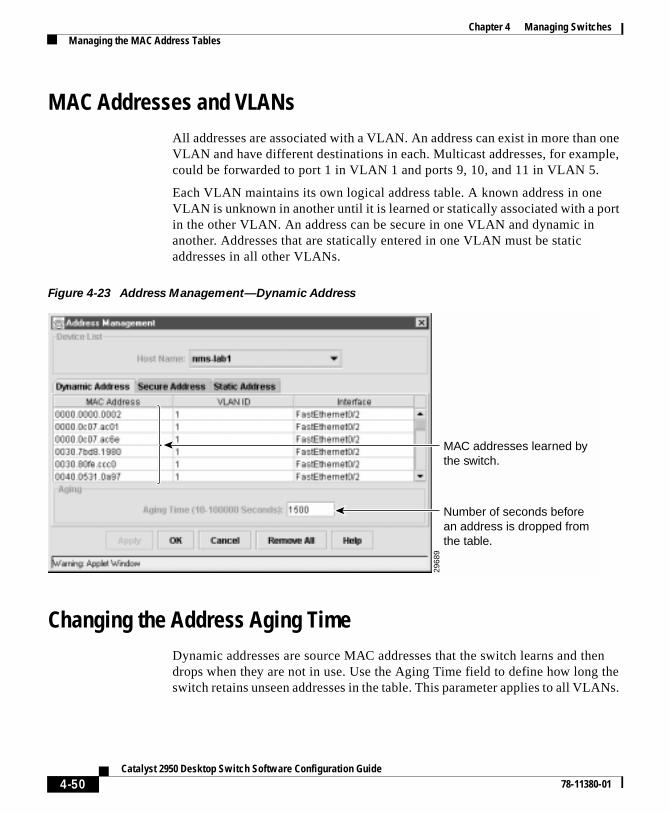
Chapter 4 Managing SwitchesManaging the MAC Address Tables
MAC Addresses and VLANsAll addresses are associated with a VLAN. An address can exist in more than oneVLAN and have different destinations in each. Multicast addresses, for example,could be forwarded to port 1 in VLAN 1 and ports 9, 10, and 11 in VLAN 5.
Each VLAN maintains its own logical address table. A known address in oneVLAN is unknown in another until it is learned or statically associated with a portin the other VLAN. An address can be secure in one VLAN and dynamic inanother. Addresses that are statically entered in one VLAN must be staticaddresses in all other VLANs.
Figure 4-23 Address Management—Dynamic Address
Changing the Address Aging TimeDynamic addresses are source MAC addresses that the switch learns and thendrops when they are not in use. Use the Aging Time field to define how long theswitch retains unseen addresses in the table. This parameter applies to all VLANs.
2968
9
Number of seconds before an address is dropped from the table.
MAC addresses learned by the switch.
4-50Catalyst 2950 Desktop Switch Software Configuration Guide
78-11380-01
Chapter 4 Managing SwitchesManaging the MAC Address Tables
CLI: Configuring the Aging Time
Setting too short an aging time can cause addresses to be prematurely removedfrom the table. Then when the switch receives a packet for an unknowndestination, it floods the packet to all ports in the same VLAN as the receivingport. This unnecessary flooding can impact performance. Setting too long anaging time can cause the address table to be filled with unused addresses; it cancause delays in establishing connectivity when a workstation is moved to a newport.
Beginning in privileged EXEC mode, follow these steps to configure the dynamicaddress table aging time.
The “Finding More Information About IOS Commands” section on page 4-1contains the path to the complete IOS documentation.
Command Purpose
Step 1 configure terminal Enter global configuration mode.
Step 2 mac-address-table aging-timeseconds
Enter the number of seconds that dynamicaddresses are to be retained in the addresstable. You can enter a number from 10 to1000000.
Step 3 end Return to privileged EXEC mode.
Step 4 show mac-address-tableaging-time
Verify your entry.
4-51Catalyst 2950 Desktop Switch Software Configuration Guide
78-11380-01

Chapter 4 Managing SwitchesManaging the MAC Address Tables
CLI: Removing Dynamic Address Entries
Beginning in privileged EXEC mode, follow these steps to remove a dynamicaddress entry:
You can remove all dynamic entries by using the clear mac-address-tabledynamic command in privileged EXEC mode.
The “Finding More Information About IOS Commands” section on page 4-1contains the path to the complete IOS documentation.
Adding Secure AddressesThe secure address table contains secure MAC addresses and their associatedports and VLANs. A secure address is a manually entered unicast address that isforwarded to only one port per VLAN. If you enter an address that is alreadyassigned to another port, the switch reassigns the secure address to the new port.
You can enter a secure port address even when the port does not yet belong to aVLAN. When the port is later assigned to a VLAN, packets destined for thataddress are forwarded to the port.
You can use the Secure Address tab (Figure 4-24) to remove individual secureaddresses or a group of them. To display this window, click the Secure Addresstab on the Address Management window. Click the New button to display the NewAddress window (Figure 4-25), and enter a new secure address.
Command Purpose
Step 1 configure terminal Enter global configuration mode.
Step 2 no mac-address-table dynamichw-addr
Enter the MAC address to be removed fromdynamic MAC address table.
Step 3 end Return to privileged EXEC mode.
Step 4 show mac-address-table Verify your entry.
4-52Catalyst 2950 Desktop Switch Software Configuration Guide
78-11380-01

Chapter 4 Managing SwitchesManaging the MAC Address Tables
Figure 4-24 Address Management—Secure Address Tab
After you have entered the secure address, select Security > Port Security fromthe menu bar to secure the port by using the Port Security window.
2970
1
4-53Catalyst 2950 Desktop Switch Software Configuration Guide
78-11380-01

Chapter 4 Managing SwitchesManaging the MAC Address Tables
Figure 4-25 New Secure Address
CLI: Adding Secure Addresses
Beginning in privileged EXEC mode, follow these steps to add a secure address:
The “Finding More Information About IOS Commands” section on page 4-1contains the path to the complete IOS documentation.
2969
0
Enter a secure MAC address for a port. Secure the port on the Port Security Page.
Command Purpose
Step 1 configure terminal Enter global configuration mode.
Step 2 mac-address-table securehw-addr interfacevlan vlan-id
Enter the MAC address, its associated port,and the VLAN ID.
Step 3 end Return to privileged EXEC mode.
Step 4 show mac-address-table secure Verify your entry.
4-54Catalyst 2950 Desktop Switch Software Configuration Guide
78-11380-01

Chapter 4 Managing SwitchesManaging the MAC Address Tables
CLI: Removing Secure Addresses
Beginning in privileged EXEC mode, follow these steps to remove a secureaddress:
You can remove all secure addresses by using the clear mac-address-tablesecure command in privileged EXEC mode.
The “Finding More Information About IOS Commands” section on page 4-1contains the path to the complete IOS documentation.
Adding and Removing Static AddressesA static address has the following characteristics:
• It is manually entered in the address table and must be manually removed.
• It can be a unicast or multicast address.
• It does not age and is retained when the switch restarts.
By clicking the Static Address tab on the Address Management window(Figure 4-23), you can add and remove static addresses. You can also define theforwarding behavior for the static address. Click Forwarding to display theModify Static Forwarding window (Figure 4-26).
On the Modify Static Forwarding window, you determine how a port that receivesa packet forwards it to another port for transmission. Because all ports areassociated with at least one VLAN, the switch acquires the VLAN ID for theaddress from the ports that you select on the forwarding map.
Command Purpose
Step 1 configure terminal Enter global configuration mode.
Step 2 no mac-address-table securehw-addr vlan vlan-id
Enter the secure MAC address, itsassociated port, and the VLAN ID to beremoved.
Step 3 end Return to privileged EXEC mode.
Step 4 show mac-address-table secure Verify your entry.
4-55Catalyst 2950 Desktop Switch Software Configuration Guide
78-11380-01

Chapter 4 Managing SwitchesManaging the MAC Address Tables
The Available Port(s) column lists the ports where a static address is received. TheForward to Port(s) column lists the ports that the address with the static addresscan be forwarded to. Select a row, and click Modify to change the entries for anaddress.
A static address in one VLAN must be a static address in other VLANs. A packetwith a static address that arrives on a VLAN where it has not been staticallyentered is flooded to all ports and not learned.
Figure 4-26 Static Address Forwarding
4-56Catalyst 2950 Desktop Switch Software Configuration Guide
78-11380-01

Chapter 4 Managing SwitchesManaging the MAC Address Tables
Configuring Static Addresses for EtherChannel Port Groups
Follow these rules if you are configuring a static address to forward to ports in anEtherChannel port group:
• For default source-based port groups, configure the static address to forwardto all ports in the port group to eliminate lost packets.
• For destination-based port groups, configure the address to forward to onlyone port in the port group to avoid the transmission of duplicate packets.
CLI: Adding Static Addresses
Static addresses are entered in the address table with an out-port-list and a VLANID, if needed. Packets are forwarded to ports listed in the out-port-list.
Note If the in-port and out-port-list parameters are all access ports in a singleVLAN, you can omit the VLAN ID. In this case, the switch recognizes theVLAN as that associated with the in-port VLAN. Otherwise, you must supplythe VLAN ID.
Beginning in privileged EXEC mode, follow these steps to add a static address:
The “Finding More Information About IOS Commands” section on page 4-1contains the path to the complete IOS documentation.
Command Purpose
Step 1 configure terminal Enter global configuration mode.
Step 2 mac-address-table statichw-addr interface out-port-listvlan vlan-id
Enter the MAC address, the ports to whichit can be forwarded, and the VLAN ID ofthose ports. For unicast static addresses,only one output port can be specified. Formulticast static addresses, more than oneoutput port can be specified.
Step 3 end Return to privileged EXEC mode.
Step 4 show mac-address-table static Verify your entry.
4-57Catalyst 2950 Desktop Switch Software Configuration Guide
78-11380-01
Chapter 4 Managing SwitchesEnabling Port Security
CLI: Removing Static Addresses
Beginning in privileged EXEC mode, follow these steps to remove a staticaddress:
You can remove all secure addresses by using the clear mac-address-table staticcommand in privileged EXEC mode.
The “Finding More Information About IOS Commands” section on page 4-1contains the path to the complete IOS documentation.
Enabling Port SecuritySecure ports restrict a port to a user-defined group of stations. When you assignsecure addresses to a secure port, the switch does not forward any packets withsource addresses outside the group of addresses you have defined. If you definethe address table of a secure port to contain only one address, the workstation orserver attached to that port is guaranteed the full bandwidth of the port.
Use the Port Security window (Figure 4-27) to enable port security on a port andto define the actions to take place when a security violation occurs. As part ofsecuring the port, you can also define the size of the address table for the port.
To display this window, select Security > Port Security from the menu bar. Tomodify port-security parameters for several ports at once, select the rows by usingthe mouse, and click Modify to display the Port Security Configuration window(Figure 4-28).
Command Purpose
Step 1 configure terminal Enter global configuration mode.
Step 2 no mac-address-table statichw-addr interface out-port-listvlan vlan-id
Enter the static MAC address, the ports towhich it can be forwarded, and the VLANID to be removed.
Step 3 end Return to privileged EXEC mode.
Step 4 show mac-address-table static Verify your entry.
4-58Catalyst 2950 Desktop Switch Software Configuration Guide
78-11380-01

Chapter 4 Managing SwitchesEnabling Port Security
Secure ports generate address-security violations under the following conditions:
• The address table of a secure port is full and the address of an incomingpacket is not found in the table.
• An incoming packet has a source address assigned as a secure address onanother port.
Limiting the number of devices that can connect to a secure port has the followingadvantages:
• Dedicated bandwidth—If the size of the address table is set to 1, the attacheddevice is guaranteed the full bandwidth of the port.
• Added security—Unknown devices cannot connect to the port.
The following fields validate port security or indicate security violations:
For the restrictions that apply to secure ports, see the “Managing ConfigurationConflicts” section on page 4-2.
Interface Port to secure.
Security Enable port security on the port.
Trap Issue a trap when an address-security violation occurs.
Shutdown Port Disable the port when an address-security violation occurs.
SecureAddresses
Number of addresses in the address table for this port. Secureports have at least one in this field.
Max Addresses Number of addresses that the address table for the port cancontain.
Security Rejects The number of unauthorized addresses seen on the port.
4-59Catalyst 2950 Desktop Switch Software Configuration Guide
78-11380-01

Chapter 4 Managing SwitchesEnabling Port Security
Figure 4-27 Port Security
Defining the Maximum Secure Address CountA secure port can have from 1 to 132 associated secure addresses. Setting oneaddress in the MAC address table for the port ensures that the attached device hasthe full bandwidth of the port.
3264
4
4-60Catalyst 2950 Desktop Switch Software Configuration Guide
78-11380-01

Chapter 4 Managing SwitchesEnabling Port Security
Figure 4-28 Port Security Configuration Pop-up
CLI: Enabling Port SecurityBeginning in privileged EXEC mode, follow these steps to enable port security.
3264
5
Send a trap when there is a security violation.
Enter 1 to guarantee the full bandwidth of the port to the connected station.
Shut down the port when there is a security violation.
Command Purpose
Step 1 configure terminal Enter global configuration mode.
Step 2 interface interface Enter interface configuration mode for theport you want to secure.
Step 3 port security max-mac-count 1 Secure the port and set the address table toone address.
Step 4 port security action shutdown Set the port to shutdown when a securityviolation occurs.
Step 5 end Return to privileged EXEC mode.
Step 6 show port security Verify the entry.
4-61Catalyst 2950 Desktop Switch Software Configuration Guide
78-11380-01

Chapter 4 Managing SwitchesConfiguring the Cisco Discovery Protocol
“Finding More Information About IOS Commands” section on page 4-1 containsthe path to the complete IOS documentation.
CLI: Disabling Port SecurityBeginning in privileged EXEC mode, follow these steps to disable port security.
The “Finding More Information About IOS Commands” section on page 4-1contains the path to the complete IOS documentation.
Configuring the Cisco Discovery ProtocolUse the Cisco IOS command-line interface and Cisco Discovery Protocol (CDP)to enable CDP for the switch, set global CDP parameters, and display informationabout neighboring Cisco devices.
CDP enables the Cluster Management Suite to display a graphical view of thenetwork. For example, the switch uses CDP to find cluster candidates andmaintain information about cluster members and other devices up to threecluster-enabled devices away from the command switch.
If necessary, you can configure CDP to discover switches running the ClusterManagement Suite up to seven devices away from the command switch. Devicesthat do not run clustering software display as edge devices, and no deviceconnected to them can be discovered by CDP.
Command Purpose
Step 1 configure terminal Enter global configuration mode.
Step 2 interface interface Enter interface configuration mode for theport you want to unsecure.
Step 3 no port security Disable port security
Step 4 end Return to privileged EXEC mode.
Step 5 show port security Verify the entry
4-62Catalyst 2950 Desktop Switch Software Configuration Guide
78-11380-01

Chapter 4 Managing SwitchesConfiguring the Cisco Discovery Protocol
Note Creating and maintaining switch clusters is based on the regular exchange ofCDP messages. Disabling CDP can interrupt cluster discovery. For moreinformation on the role that CDP plays in clustering, see the “AutomaticallyDiscovering Cluster Candidates” section on page 3-6.
CLI: Configuring CDP for Extended DiscoveryYou can change the default configuration of CDP on the command switch tocontinue discovering devices up to seven hops away. Figure 4-29 shows acommand switch that can discover candidates up to seven devices away from it.Figure 4-29 also shows the command switch connected to a Catalyst 5000 seriesswitch. Because the Catalyst 5000 is a CDP device that does not supportclustering, the command switch cannot learn about cluster candidate switchesconnected to it, even if they are running the Cluster Management Suite.
Figure 4-29 Discovering Cluster Candidates via CDP
Catalyst 5000 series(CDP devicethat does not
support clustering)
Undiscloseddevice displaysas edge device
Cluster command switch
3 hops fromcommand switch
Up to 7 hopsfrom command switch
3301
9
4-63Catalyst 2950 Desktop Switch Software Configuration Guide
78-11380-01

Chapter 4 Managing SwitchesIGMP Snooping
Beginning in privileged EXEC mode, follow these steps to configure the numberof hops that CDP discovers.
The “Finding More Information About IOS Commands” section on page 4-1contains the path to the complete IOS documentation.
IGMP SnoopingInternet Group Management Protocol (IGMP) snooping constrains the flooding ofmulticast traffic by dynamically configuring the interfaces so that multicast trafficis forwarded only to those interfaces associated with IP multicast devices. TheLAN switch snoops on the IGMP traffic between the host and the router and keepstrack of multicast groups and member ports. When the switch receives an IGMPjoin report from a host for a particular multicast group, the switch adds the hostport number to the associated multicast forwarding table entry. When it receivesan IGMP Leave Group message from a host, it removes the host port from thetable entry. After it relays the IGMP queries from the multicast router, it deletesentries periodically if it does not receive any IGMP membership reports from themulticast clients.
When IGMP snooping is enabled, the multicast router sends out periodic IGMPgeneral queries to all VLANs. The switch responds to the router queries with onlyone join request per MAC multicast group, and the switch creates one entry perVLAN in the Layer 2 forwarding table for each MAC group from which itreceives an IGMP join request. All hosts interested in this multicast traffic sendjoin requests and are added to the forwarding table entry.
Command Purpose
Step 1 configure terminal Enter global configuration mode.
Step 2 cluster discovery hop-countnumber
Enter the number of hops that you wantCDP to search for cluster candidates.
Step 3 end Return to privileged EXEC mode.
Step 4 show running-config Verify the change by displaying the runningconfiguration file. The hop count isdisplayed in the file.
4-64Catalyst 2950 Desktop Switch Software Configuration Guide
78-11380-01

Chapter 4 Managing SwitchesIGMP Snooping
Layer 2 multicast groups learned through IGMP snooping are dynamic. However,you can statically configure MAC multicast groups by using the ip igmpsnooping vlan static command. If you specify group membership for a multicastgroup address statically, your setting supersedes any automatic manipulation byIGMP snooping. Multicast group membership lists can consist of bothuser-defined and IGMP snooping-learned settings.
Catalyst 2950 switches support a maximum of 255 IP multicast groups andsupport both IGMP version 1 and IGMP version 2.
If a port spanning-tree, a port group, or a VLAN ID change occurs, the IGMPsnooping-learned multicast groups from this port on the VLAN are purged.
In the IP multicast-source-only environment, the switch learns the IP multicastgroup from the IP multicast data stream and only forwards traffic to the multicastrouter ports.
Use the IGMP Snooping window (Figure 4-30) to enable the IGMP snoopingfeature. To display this window, select Device > IGMP Snooping from the menubar.
You can use this window to perform the following tasks:
• Enable or disable IGMP snooping
• Enable or disable Immediate-Leave processing
• Join or leave a multicast group
• Configure a multicast router
4-65Catalyst 2950 Desktop Switch Software Configuration Guide
78-11380-01

Chapter 4 Managing SwitchesIGMP Snooping
Figure 4-30 IGMP Snooping
Enabling or Disabling IGMP SnoopingBy default, IGMP snooping is globally enabled on the switch. When globallyenabled or disabled, it is also enabled or disabled in all existing VLAN interfaces.By default, IGMP snooping is enabled on all VLANs, but it can be enabled anddisabled on a per-VLAN basis.
Global IGMP snooping overrides the per-VLAN IGMP snooping capability. Ifglobal snooping is disabled, you cannot enable VLAN snooping. If globalsnooping is enabled, you can enable or disable snooping on a VLAN basis.
To modify the IGMP snooping settings on a per-VLAN basis, select a row, andclick Modify. You can modify the settings as shown in Figure 4-31.
IGMP snooping is enabled by default. Deselect this if you want to disable IGMP snooping on the entire device.
4723
6
4-66Catalyst 2950 Desktop Switch Software Configuration Guide
78-11380-01

Chapter 4 Managing SwitchesIGMP Snooping
Figure 4-31 Modify the IGMP Snooping Settings
CLI: Enabling or Disabling IGMP Snooping
Beginning in privileged EXEC mode, follow these steps to enable IGMP snoopingglobally on the switch:
To globally disable IGMP snooping on all existing VLAN interfaces, use the noip igmp snooping global command.
Enable or disable IGMP snooping.
Enable or disable Immediate Leave.
Select pim-dvmrp or cgmp.
4724
1
Command Purpose
Step 1 configure terminal Enter global configuration mode.
Step 2 ip igmp snooping Globally enable IGMP snooping in allexisting VLAN interfaces.
Step 3 end Return to privileged EXEC mode.
Step 4 show ip igmp snooping Display snooping configuration.
Step 5 copy running-configstartup-config
(Optional) Save your configuration to thestartup configuration.
4-67Catalyst 2950 Desktop Switch Software Configuration Guide
78-11380-01
Chapter 4 Managing SwitchesIGMP Snooping
Beginning in privileged EXEC mode, follow these steps to enable IGMP snoopingon a VLAN interface:
To disable IGMP snooping on a VLAN interface, use the global configurationcommand no ip igmp snooping vlan vlan_id for the specified VLAN number (forexample, vlan1).
The “Finding More Information About IOS Commands” section on page 4-1contains the path to the complete IOS documentation.
CLI: Enabling IGMP Immediate-Leave Processing
When you enable IGMP Immediate-Leave processing, the switch immediatelyremoves a port from the IP multicast group when it detects an IGMP version 2leave message on that port. Immediate-Leave processing allows the switch toremove an interface that sends a leave message from the forwarding table withoutfirst sending out group specific queries to the interface. You should use theImmediate-Leave feature only when there is only a single receiver present onevery port in the VLAN.
Command Purpose
Step 1 configure terminal Enter global configuration mode.
Step 2 ip igmp snooping vlan vlan_id Enable IGMP snooping on the VLANinterface.
Step 3 end Return to privileged EXEC mode.
Step 4 show ip igmp snooping [vlanvlan_id]
Display snooping configuration.
(Optional) vlan_id is the number of theVLAN.
Step 5 copy running-configstartup-config
(Optional) Save your configuration to thestartup configuration.
4-68Catalyst 2950 Desktop Switch Software Configuration Guide
78-11380-01

Chapter 4 Managing SwitchesIGMP Snooping
Beginning in privileged EXEC mode, follow these steps to enable IGMPImmediate-Leave processing:
To disable Immediate-Leave processing, follow Steps 1 and 2 to enter interfaceconfiguration mode, and use the command no ip igmp snooping vlan vlan_idimmediate-leave.
The “Finding More Information About IOS Commands” section on page 4-1contains the path to the complete IOS documentation.
Setting the Snooping Method
Multicast-capable router ports are added to the forwarding table for every IPmulticast entry. The switch learns of such ports through one of these methods:
• Snooping on PIM and DVMRP packets
• Listening to CGMP self-join packets from other routers
• Statically connecting to a multicast router port with the ip igmp snoopingmrouter command
You can configure the switch to either snoop on Protocol IndependentMulticast/Distance Vector Multicast Routing Protocol (PIM/DVMRP) packets orto listen to CGMP self-join packets. By default, the switch snoops onPIM/DVMRP packets on all VLANs. To learn of multicast router ports throughonly CGMP self-join packets, use the ip igmp snooping vlan vlan_id mrouterlearn cgmp global configuration command. When this command is used, therouter listens only to CGMP self-join packets and no other CGMP packets. Tolearn of multicast router ports through only PIM-DVMRP packets, use the ipigmp snooping vlan vlan_id mrouter learn pim-dvmrp interface command.
Command Purpose
Step 1 configure terminal Enter global configuration mode.
Step 2 ip igmp snooping vlan vlan_idimmediate-leave
Enable IGMP Immediate-Leave processingon the VLAN interface.
Step 3 end Return to privileged EXEC mode.
4-69Catalyst 2950 Desktop Switch Software Configuration Guide
78-11380-01

Chapter 4 Managing SwitchesIGMP Snooping
Joining a Multicast GroupWhen a host connected to the switch wants to join an IP multicast group, it sendsan IGMP join message, specifying the IP multicast group it wants to join. Whenthe switch receives this message, it adds the port to the IP multicast group portaddress entry in the forwarding table.
Figure 4-32 Initial IGMP Join Message
Refer to Figure 4-32. Host 1 wants to join multicast group 224.1.2.3 andmulticasts an unsolicited IGMP membership report (IGMP join message) to thegroup with the equivalent MAC destination address of 0100.5E01.0203. Theswitch recognizes IGMP packets and forwards them to the CPU. When the CPUreceives the IGMP report multicast by Host 1, the CPU uses the information to setup a multicast forwarding table entry as shown in Table 4-4 that includes the portnumbers of Host 1 and the router.
CAMTable
CPU
Host 1 Host 2 Host 3 Host 4
Router A
IGMP Report 224.1.2.3
Catalyst 2950 switch
1
0
2 3 4 5
4793
3
4-70Catalyst 2950 Desktop Switch Software Configuration Guide
78-11380-01

Chapter 4 Managing SwitchesIGMP Snooping
Note that the architecture of the switch allows the CPU to distinguish IGMPinformation packets from other packets for the multicast group. The switchrecognizes the IGMP packets through it’s filter engine. This prevents the CPUfrom becoming overloaded with multicast frames.
The entry in the multicast forwarding table tells the switching engine to sendframes addressed to the 0100.5E01.0203 multicast MAC address that are notIGMP packets (!IGMP) to the router and to the host that has joined the group.
If another host (for example, Host 4) sends an IGMP join message for the samegroup (Figure 4-33), the CPU receives that message and adds the port number ofHost 4 to the CAM table as shown in Table 4-5.
Figure 4-33 Second Host Joining a Multicast Group
Table 4-4 IP Multicast Forwarding Table
Destination Address Type of Packet Ports
0100.5e01.0203 !IGMP 1, 2
CAMTable
CPU
Host 1 Host 2 Host 3 Host 4
Router A
Catalyst 2950 switch
1
0
2 3 4 5
4721
6
4-71Catalyst 2950 Desktop Switch Software Configuration Guide
78-11380-01

Chapter 4 Managing SwitchesIGMP Snooping
Statically Configuring a Host to Join a Group
Ports normally join multicast groups through the IGMP report message, but youcan also statically configure a host on an interface.
Select the Multicast Group tab on the IGMP snooping window (Figure 4-30) toview the current settings. Select the row you want to modify from the MulticastGroups window (Figure 4-34), and click Modify to change the settings. Use theMulticast Groups window (Figure 4-35) to add or remove ports from a multicastgroup.
Table 4-5 Updated Multicast Forwarding Table
Destination Address Type of Packet Ports
0100.5e01.0203 !IGMP 1, 2, 5
4-72Catalyst 2950 Desktop Switch Software Configuration Guide
78-11380-01

Chapter 4 Managing SwitchesIGMP Snooping
Figure 4-34 Multicast Groups
4-73Catalyst 2950 Desktop Switch Software Configuration Guide
78-11380-01

Chapter 4 Managing SwitchesIGMP Snooping
Figure 4-35 Modify Multicast Groups
4-74Catalyst 2950 Desktop Switch Software Configuration Guide
78-11380-01

Chapter 4 Managing SwitchesIGMP Snooping
CLI: Statically Configuring a Interface to Join a Group
Beginning in privileged EXEC mode, follow these steps to add a port as a memberof a multicast group:
Command Purpose
Step 1 configure terminal Enter global configuration mode
Step 2 ip igmp snooping vlan vlan_idstatic mac-address interfaceinterface-num
Statically configure a port as a member of amulticast group:
• vlan_id is the multicast group VLANID.
• mac-address is the group MACaddress.
• interface is the member port.
• FastEthernet interface number tospecify a Fast Ethernet 802.3 interface.
• Gigabit Ethernet interface-number tospecify a Gigabit Ethernet 802.3zinterface.
Step 3 end Return to privileged EXEC mode.
Step 4 show mac-address-tablemulticast [vlan vlan-id] [user |igmp-snooping] [count]
Display MAC address table entries for aVLAN.
• vlan_id (Optional) is the multicastgroup VLAN ID.
• user displays only the user-configuredmulticast entries.
• igmp-snooping displays entrieslearned via IGMP snooping.
• count displays only the total number ofentries for the selected criteria, not theactual entries.
Step 5 copy running-configstartup-config
(Optional) Save your configuration to thestartup configuration.
4-75Catalyst 2950 Desktop Switch Software Configuration Guide
78-11380-01

Chapter 4 Managing SwitchesIGMP Snooping
The “Finding More Information About IOS Commands” section on page 4-1contains the path to the complete IOS documentation.
Leaving a Multicast GroupThe router sends periodic IP multicast general queries, and the switch responds tothese queries with one join response per MAC multicast group. As long as at leastone host in the VLAN needs multicast traffic, the switch responds to the routerqueries, and the router continues forwarding the multicast traffic to the VLAN.The switch only forwards IP multicast group traffic to those hosts listed in theforwarding table for that IP multicast group.
When hosts need to leave a multicast group, they can either ignore the periodicgeneral-query requests sent by the router, or they can send a leave message. Whenthe switch receives a leave message from a host, it sends out a group-specificquery to determine if any devices behind that interface are interested in traffic forthe specific multicast group. If, after a number of queries, the router processorreceives no reports from a VLAN, it removes the group for the VLAN from itsIGMP cache.
Configuring a Multicast Router PortSelect the Multicast Router Port tab on the IGMP snooping window(Figure 4-30) to view the current settings. Select the row that you want to modifyfrom the Multicast Router Ports window (Figure 4-36), and click Modify tochange the settings. Use the Multicast Router Ports window (Figure 4-37) to addor remove ports.
4-76Catalyst 2950 Desktop Switch Software Configuration Guide
78-11380-01

Chapter 4 Managing SwitchesIGMP Snooping
Figure 4-36 Multicast Router Ports
4-77Catalyst 2950 Desktop Switch Software Configuration Guide
78-11380-01

Chapter 4 Managing SwitchesIGMP Snooping
Figure 4-37 Modify Multicast Router Ports
4-78Catalyst 2950 Desktop Switch Software Configuration Guide
78-11380-01

Chapter 4 Managing SwitchesIGMP Snooping
CLI: Configuring a Multicast Router Port
Beginning in privileged EXEC mode, follow these steps to enable a staticconnection to a multicast router:
Command Purpose
Step 1 configure terminal Enter global configuration mode.
Step 2 ip igmp snooping vlan vlan_idmrouter {interface interface}{learn method}
Specify the multicast router VLAN ID (1 to1001).
Specify the interface to the multicast routeras one of the following:
• FastEthernet interface number tospecify a Fast Ethernet 802.3 interface(fa0/x, where x is the port number).
• GigabitEthernet interface-number tospecify a Gigabit Ethernet 802.3zinterface (gi0/x, where x is the portnumber).
Specify the multicast router learningmethod:
• cgmp to specify listening for CGMPpackets.
• pim-dvmrp to specify snoopingPIM-DVMRP packets
Step 3 end Return to privileged EXEC mode.
Step 4 show ip igmp snooping [vlanvlan_id]
Verify that IGMP snooping is enabled onthe VLAN interface.
Step 5 show ip igmp snooping mrouter[vlan vlan_id]
Display information on dynamicallylearned and manually configured multicastrouter interfaces.
Step 6 copy running-configstartup-config
(Optional) Save your configuration to thestartup configuration.
4-79Catalyst 2950 Desktop Switch Software Configuration Guide
78-11380-01

Chapter 4 Managing SwitchesConfiguring the Spanning Tree Protocol
The “Finding More Information About IOS Commands” section on page 4-1contains the path to the complete IOS documentation.
Configuring the Spanning Tree ProtocolSpanning Tree Protocol (STP) provides path redundancy while preventingundesirable loops in the network. Only one active path can exist between any twostations. STP calculates the best loop-free path throughout the network.
Supported STP InstancesYou create an STP instance when you assign an interface to a VLAN. The STPinstance is removed when the last interface is moved to another VLAN. You canconfigure switch and port parameters before an STP instance is created. Theseparameters are applied when the STP instance is created. You can change allVLANs on a switch by using the show spanning-tree [vlan stp-list] privilegedEXEC command when you enter STP commands through the CLI. For moreinformation, refer to the Catalyst 2950 Desktop Switch Command Reference.
Catalyst 2950 switches support only 64 VLANs. For more information aboutVLANs, see Chapter 5, “Creating and Maintaining VLANs.”
Each VLAN is a separate STP instance. If you have already used up all availableSTP instances on a switch, adding another VLAN anywhere in the VLAN TrunkProtocol (VTP) domain creates a VLAN that is not running STP on that switch.For example, if 64 VLANs are defined in the VTP domain, you can enable STPon those 64 VLANs. The remaining VLANs must operate with STP disabled.
You can disable STP on one of the VLANs where it is running and then enable iton the VLAN where you want it to run. Use the no spanning-tree vlan vlan-idglobal configuration command to disable STP on a specific VLAN, and use thespanning-tree vlan vlan-id global configuration command to enable STP on thedesired VLAN.
4-80Catalyst 2950 Desktop Switch Software Configuration Guide
78-11380-01

Chapter 4 Managing SwitchesConfiguring the Spanning Tree Protocol
Caution Switches that are not running spanning tree still forward BPDUs that theyreceive so that the other switches on the VLAN that have a running STPinstance can break loops. Therefore, spanning tree must be running on enoughswitches so that it can break all the loops in the network. For example, at leastone switch on each loop in the VLAN must be running spanning tree. It is notabsolutely necessary to run spanning tree on all switches in the VLAN;however, if you are running STP only on a minimal set of switches, anincautious change to the network that introduces another loop into the VLANcan result in a broadcast storm.
Note If you have the default allowed list on the trunk ports of that switch, the newVLAN is carried on all trunk ports. Depending on the topology of the network,this could create a loop in the new VLAN that will not be broken, particularlyif there are several adjacent switches that all have run out of STP instances.You can prevent this by setting allowed lists on the trunk ports of switches thathave used up their allocation of STP instances. Setting up allowed lists is notnecessary in many cases andadding another VLAN to the network wouldbecome more labor-intensive.
Use the Spanning Tree Protocol (STP) window (Figure 4-38) to changeparameters for STP, an industry standard for avoiding loops in switched networks.Each VLAN supports its own instance of STP.
Spanning Tree Protocol (STP) provides path redundancy while preventingundesirable loops in the network. Only one active path can exist between any twostations. STP calculates the best loop-free path throughout the network.
You can use this window to perform the following tasks:
• Disable STP for a switch or group of switches.
• Change STP parameters for per VLAN (STP implementation, switch priority,Bridge Protocol Data Unit (BPDU) message interval, hello BPDU interval,and the forwarding time).
• Change STP port parameters per VLAN (Port Fast feature, root cost, pathcost, port priority).
4-81Catalyst 2950 Desktop Switch Software Configuration Guide
78-11380-01
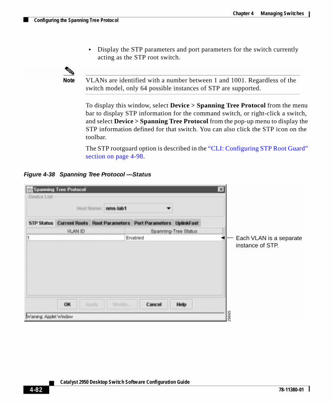
Chapter 4 Managing SwitchesConfiguring the Spanning Tree Protocol
• Display the STP parameters and port parameters for the switch currentlyacting as the STP root switch.
Note VLANs are identified with a number between 1 and 1001. Regardless of theswitch model, only 64 possible instances of STP are supported.
To display this window, select Device > Spanning Tree Protocol from the menubar to display STP information for the command switch, or right-click a switch,and select Device > Spanning Tree Protocol from the pop-up menu to display theSTP information defined for that switch. You can also click the STP icon on thetoolbar.
The STP rootguard option is described in the “CLI: Configuring STP Root Guard”section on page 4-98.
Figure 4-38 Spanning Tree Protocol —Status
Each VLAN is a separate instance of STP.
2966
5
4-82Catalyst 2950 Desktop Switch Software Configuration Guide
78-11380-01

Chapter 4 Managing SwitchesConfiguring the Spanning Tree Protocol
Using STP to Support Redundant ConnectivityYou can create a redundant backbone with STP by connecting two of the switchports to another device or to two different devices. STP automatically disables oneport but enables it if the other port is lost. If one link is high-speed and the otherlow-speed, the low-speed link is always disabled. If the speed of the two links isthe same, the port priority and port ID are added together, and STP disables thelink with the lowest value.
You can also create redundant links between switches by using EtherChannel portgroups. For more information on creating port groups, see the “CreatingEtherChannel Port Groups” section on page 4-11.
Accelerating Aging to Retain ConnectivityThe default for aging dynamic addresses is 5 minutes. However, a reconfigurationof the spanning tree can cause many station locations to change. Because thesestations could be unreachable for 5 minutes or more during a reconfiguration, theaddress-aging time is accelerated so that station addresses can be dropped fromthe address table and then relearned. The accelerated aging is the same as theforward-delay parameter value when STP reconfigures.
Because each VLAN is a separate instance of STP, the switch accelerates agingon a per-VLAN basis. A reconfiguration of STP on one VLAN can cause thedynamic addresses learned on that VLAN to be subject to accelerated aging.Dynamic addresses on other VLANs can be unaffected and remain subject to theaging interval entered for the switch.
Disabling STP ProtocolSTP is enabled by default. Disable STP only if you are sure there are no loops inthe network topology.
Caution When STP is disabled and loops are present in the topology, excessive trafficand indefinite packet duplication can drastically reduce network performance.
4-83Catalyst 2950 Desktop Switch Software Configuration Guide
78-11380-01

Chapter 4 Managing SwitchesConfiguring the Spanning Tree Protocol
Figure 4-39 STP Pop-up
CLI: Disabling STPBeginning in privileged EXEC mode, follow these steps to disable STP:
The “Finding More Information About IOS Commands” section on page 4-1contains the path to the complete IOS documentation.
Configuring Redundant Links By Using STP UplinkFastSwitches in hierarchical networks can be grouped into backbone switches,distribution switches, and access switches. Figure 4-40 shows a complex networkwhere distribution switches and access switches each have at least one redundantlink that STP blocks to prevent loops.
2973
3
Command Purpose
Step 1 configure terminal Enter global configuration mode.
Step 2 no spanning-tree vlan stp-list Disable STP on a VLAN.
Step 3 end Return to privileged EXEC mode.
Step 4 show spanning-tree Verify your entry.
4-84Catalyst 2950 Desktop Switch Software Configuration Guide
78-11380-01

Chapter 4 Managing SwitchesConfiguring the Spanning Tree Protocol
If a switch looses connectivity, the switch begins using the alternate paths as soonas STP selects a new root port. When STP reconfigures the new root port, otherports flood the network with multicast packets, one for each address that waslearned on the port. You can limit these bursts of multicast traffic by reducing themax-update-rate parameter (the default for this parameter is 150 packets persecond). However, if you enter zero, station-learning frames are not generated, sothe STP topology converges more slowly after a loss of connectivity.
STP UplinkFast is an enhancement that accelerates the choice of a new root portwhen a link or switch fails or when STP reconfigures itself. The root porttransitions to the forwarding state immediately without going through thelistening and learning states, as it would with normal STP procedures. UplinkFastis most useful in edge or access switches and might not be appropriate forbackbone devices.
You can change STP parameters by using the UplinkFast tab of the Spanning TreeProtocol window or by using the CLI. The “Configuring the Spanning TreeProtocol” section on page 4-80 describes the use of the Spanning Tree Protocolwindow.
To display this window, select Device > Spanning-Tree Protocol from the menubar. Then click the UplinkFast tab.
4-85Catalyst 2950 Desktop Switch Software Configuration Guide
78-11380-01

Chapter 4 Managing SwitchesConfiguring the Spanning Tree Protocol
Figure 4-40 Switches in a Hierarchical Network
3500 XL 3500 XL
2900 XL 2900 XL 2950
2900 XL 2900 XL 2950 2950
Active link
Blocked link
Root bridge
Backbone switches
Distribution switches
Access switches
4496
0
4-86Catalyst 2950 Desktop Switch Software Configuration Guide
78-11380-01

Chapter 4 Managing SwitchesConfiguring the Spanning Tree Protocol
CLI: Enabling STP UplinkFastWhen you enable UplinkFast, it is enabled for the entire switch and cannot beenabled for individual VLANs.
Beginning in privileged EXEC mode, follow these steps to configure UplinkFast:
When UplinkFast is enabled, the bridge priority of all VLANs is set to 49152, andthe path cost of all ports and VLAN trunks is increased by 3000. This changereduces the chance that the switch will become the root port. When UplinkFast isdisabled, the bridge priorities of all VLANs and path costs of all ports are set todefault values.
The “Finding More Information About IOS Commands” section on page 4-1contains the path to the complete IOS documentation.
Changing STP Parameters for a VLANTo change STP parameters for a VLAN, select Device > Spanning Tree Protocolfrom the menu bar, select the VLAN ID of the STP instance to change, and clickRoot Parameters.
Command Purpose
Step 1 configure terminal Enter global configuration mode.
Step 2 spanning-tree uplinkfastmax-update-rate pkts-per-second
Enable UplinkFast on the switch.
The range is from 0 to 1000 packets persecond; The default is 150.
If you set the rate to 0, station-learningframes are not generated, so the STPtopology converges more slowly after a lossof connectivity.
Step 3 exit Return to privileged EXEC mode.
Step 4 show spanning-tree Verify your entries.
4-87Catalyst 2950 Desktop Switch Software Configuration Guide
78-11380-01

Chapter 4 Managing SwitchesConfiguring the Spanning Tree Protocol
Figure 4-41 Spanning Tree Protocol Current Root Tab
In Figure 4-41, the parameters under the heading Current Spanning-Tree Root areread-only. The MAC Address field shows the MAC address of the switchcurrently acting as the root for each VLAN; the remaining parameters show theother STP settings for the root switch for each VLAN. The root switch is theswitch with the highest priority and transmits topology frames to other switchesin the spanning tree.
In the Spanning Tree Protocol window (Figure 4-42), you can change the rootparameters for the VLANs on a selected switch. The following fields(Figure 4-42) define how your switch responds when STP reconfigures itself.
Parameters to take effect when the VLAN becomes the root.
2966
6
Protocol Implementation of STP to use.
Select one of the menu bar items: IBM, or IEEE. The default isIEEE.
Priority Value used to identify the root switch. The switch with the lowestvalue has the highest priority and is selected as the root.
Enter a number from 0 to 65535.
4-88Catalyst 2950 Desktop Switch Software Configuration Guide
78-11380-01

Chapter 4 Managing SwitchesConfiguring the Spanning Tree Protocol
Max age Number of seconds a switch waits without receiving STPconfiguration messages before attempting a reconfiguration. Thisparameter takes effect when a switch is operating as the rootswitch. Switches not acting as the root use the root-switch Maxage parameter.
Enter a number from 6 to 200.
Hello Time Number of seconds between the transmission of hello messages,which indicate that the switch is active. Switches not acting as aroot switch use the root-switch Hello-time value.
Enter a number from 1 to 10.
ForwardDelay
Number of seconds a port waits before changing from its STPlearning and listening states to the forwarding state. This wait isnecessary so that other switches on the network ensure no loop isformed before they allow the port to forward packets.
Enter a number from 4 to 200.
4-89Catalyst 2950 Desktop Switch Software Configuration Guide
78-11380-01

Chapter 4 Managing SwitchesConfiguring the Spanning Tree Protocol
Figure 4-42 Spanning Tree Protocol Root Parameters Tab
CLI: Changing the STP Implementation
Beginning in privileged EXEC mode, follow these steps to change the STPimplementation. The stp-list is the list of VLANs to which the STP commandapplies.
2973
4
Command Purpose
Step 1 configure terminal Enter global configuration mode.
Step 2 spanning-tree [vlan stp-list]protocol {ieee | ibm}
Specify the STP implementation to be usedfor a spanning-tree instance.
Step 3 end Return to privileged EXEC mode.
Step 4 show spanning-tree Verify your entry.
4-90Catalyst 2950 Desktop Switch Software Configuration Guide
78-11380-01

Chapter 4 Managing SwitchesConfiguring the Spanning Tree Protocol
The “Finding More Information About IOS Commands” section on page 4-1contains the path to the complete IOS documentation.
CLI: Changing the Switch Priority
Beginning in privileged EXEC mode, follow these steps to change the switchpriority and affect which switch is the root switch. The stp-list is the list ofVLANs to which the STP command applies.
The “Finding More Information About IOS Commands” section on page 4-1contains the path to the complete IOS documentation.
Command Purpose
Step 1 configure terminal Enter global configuration mode.
Step 2 spanning-tree [vlan stp-list]priority bridge-priority
Configure the switch priority for thespecified spanning-tree instance.
Enter a number from 0 to 65535; the lowerthe number, the more likely the switch willbe chosen as the root switch.
Step 3 end Return to privileged EXEC mode.
Step 4 show spanning-tree Verify your entry.
4-91Catalyst 2950 Desktop Switch Software Configuration Guide
78-11380-01

Chapter 4 Managing SwitchesConfiguring the Spanning Tree Protocol
CLI: Changing the BPDU Message Interval
Beginning in privileged EXEC mode, follow these steps to change the BPDUmessage interval (max age time). The stp-list is the list of VLANs to which theSTP command applies.
The “Finding More Information About IOS Commands” section on page 4-1contains the path to the complete IOS documentation.
CLI: Changing the Hello BPDU Interval
Beginning in privileged EXEC mode, follow these steps to change the helloBPDU interval (hello time). The stp-list is the list of VLANs to which the STPcommand applies.
Command Purpose
Step 1 configure terminal Enter global configuration mode.
Step 2 spanning-tree [vlan stp-list]max-age seconds
Specify the interval between messages thespanning tree receives from the root switch.
The maximum age is the number of seconds aswitch waits without receiving STPconfiguration messages before attempting areconfiguration. Enter a number from 6 to 200.
Step 3 end Return to privileged EXEC mode.
Step 4 show spanning-tree Verify your entry.
Command Purpose
Step 1 configure terminal Enter global configuration mode.
Step 2 spanning-tree [vlan stp-list]hello-time seconds
Specify the interval between hello BPDUs.
Hello messages indicate that the switch isactive. Enter a number from 1 to 10.
Step 3 end Return to privileged EXEC mode.
Step 4 show spanning-tree Verify your entry.
4-92Catalyst 2950 Desktop Switch Software Configuration Guide
78-11380-01

Chapter 4 Managing SwitchesConfiguring the Spanning Tree Protocol
The “Finding More Information About IOS Commands” section on page 4-1contains the path to the complete IOS documentation.
CLI: Changing the Forwarding Delay Time
Beginning in privileged EXEC mode, follow these steps to change the forwardingdelay time. The stp-list is the list of VLANs to which the STP command applies.
The “Finding More Information About IOS Commands” section on page 4-1contains the path to the complete IOS documentation.
Changing STP Port ParametersThe ports listed on this window (Figure 4-43) belong to the VLAN selected in theVLAN ID list above the table of parameters. To change STP port options, selectDevice > Spanning Tree Protocol from the menu bar, select the VLAN ID, andclick Modify STP Parameters.
Command Purpose
Step 1 configure terminal Enter global configuration mode.
Step 2 spanning-tree [vlan stp-list]forward-time seconds
Specify the forwarding time for thespecified spanning-tree instance.
The forward delay is the number of secondsa port waits before changing from its STPlearning and listening states to theforwarding state. Enter a number from 4 to200.
Step 3 end Return to privileged EXEC mode.
Step 4 show spanning-tree Verify your entry.
4-93Catalyst 2950 Desktop Switch Software Configuration Guide
78-11380-01

Chapter 4 Managing SwitchesConfiguring the Spanning Tree Protocol
Use the following fields (Figure 4-43) to check the status of ports that are notforwarding due to STP:
Port The interface and port number. FastEthernet0/1 refers to port1x.
State The current state of the port. A port can be in one of thefollowing states:
Listening Port is not participating in the frame-forwarding process, butis progressing towards a forwarding state. The port is notlearning addresses.
Learning Port is not forwarding frames but is learning addresses.
Forwarding Port is forwarding frames and learning addresses.
Disabled Port has been removed from STP operation.
Down Port has no physical link.
Broken One end of the link is configured as an access port and theother end is configured as an 802.1Q trunk port, or both endsof the link are configured as 802.1Q trunk ports but havedifferent native VLAN IDs.
4-94Catalyst 2950 Desktop Switch Software Configuration Guide
78-11380-01

Chapter 4 Managing SwitchesConfiguring the Spanning Tree Protocol
Figure 4-43 Spanning Tree Protocol Port Parameters Tab
Enabling the Port Fast Feature
The Port Fast feature brings a port directly from a blocking state into a forwardingstate. This feature is useful when a connected server or workstation times outbecause its port is going through the normal cycle of STP status changes. The onlytime a port with Port Fast enabled goes through the normal cycle of STP statuschanges is when the switch is restarted.
To enable the Port Fast feature on the Port Configuration pop-up (Figure 4-44),select a row in the Port Parameters tab, and click Modify.
Caution Enabling this feature on a port connected to a switch or hub could prevent STPfrom detecting and disabling loops in your network, and this could causebroadcast storms and address-learning problems.
Shows current STP state of port.
Enable to accelerate STP reconfiguration if port is connected to an end station.
2966
4
Select a VLAN from the list.
4-95Catalyst 2950 Desktop Switch Software Configuration Guide
78-11380-01

Chapter 4 Managing SwitchesConfiguring the Spanning Tree Protocol
Figure 4-44 STP Port Configuration Pop-up
You can modify the following parameters and enable the Port Fast feature byselecting a row on the Port Parameters tab and clicking Modify.
2973
6Port Fast Enable to bring the port more quickly to an STP forwarding state.
Path Cost A lower path cost represents higher-speed transmission. This canaffect which port remains enabled in the event of a loop.
Enter a number from 1 to 65535. The default is 100 for 10 Mbps,19 for 100 Mbps, 4 for 1 Gbps, 2 for 10 Gbps, and 1 for interfaceswith speeds greater than 10 Gbps.
Priority Number used to set the priority for a port. A higher number hashigher priority. Enter a number from 0 to 65535.
4-96Catalyst 2950 Desktop Switch Software Configuration Guide
78-11380-01
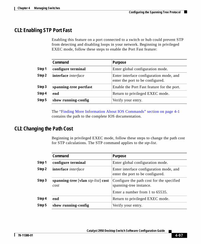
Chapter 4 Managing SwitchesConfiguring the Spanning Tree Protocol
CLI: Enabling STP Port Fast
Enabling this feature on a port connected to a switch or hub could prevent STPfrom detecting and disabling loops in your network. Beginning in privilegedEXEC mode, follow these steps to enable the Port Fast feature:
The “Finding More Information About IOS Commands” section on page 4-1contains the path to the complete IOS documentation.
CLI: Changing the Path Cost
Beginning in privileged EXEC mode, follow these steps to change the path costfor STP calculations. The STP command applies to the stp-list.
Command Purpose
Step 1 configure terminal Enter global configuration mode.
Step 2 interface interface Enter interface configuration mode, andenter the port to be configured.
Step 3 spanning-tree portfast Enable the Port Fast feature for the port.
Step 4 end Return to privileged EXEC mode.
Step 5 show running-config Verify your entry.
Command Purpose
Step 1 configure terminal Enter global configuration mode.
Step 2 interface interface Enter interface configuration mode, andenter the port to be configured.
Step 3 spanning-tree [vlan stp-list] costcost
Configure the path cost for the specifiedspanning-tree instance.
Enter a number from 1 to 65535.
Step 4 end Return to privileged EXEC mode.
Step 5 show running-config Verify your entry.
4-97Catalyst 2950 Desktop Switch Software Configuration Guide
78-11380-01

Chapter 4 Managing SwitchesConfiguring the Spanning Tree Protocol
The “Finding More Information About IOS Commands” section on page 4-1contains the path to the complete IOS documentation.
CLI: Changing the Port Priority
Beginning in privileged EXEC mode, follow these steps to change the portpriority, which is used when two switches tie for position as the root switch. Thestp-list is the list of VLANs to which the STP command applies.
The “Finding More Information About IOS Commands” section on page 4-1contains the path to the complete IOS documentation.
CLI: Configuring STP Root GuardThe Layer 2 network of a service provider (SP) can include many connections toswitches that are not owned by the SP. In such a topology, STP can reconfigureitself and select a customer switch as the STP root switch, as shown inFigure 4-45. You can avoid this possibility by configuring the root guardparameter on ports that connect to switches outside of your network. If a switchoutside the network becomes the root switch, the port is blocked, and STP selectsa new root switch.
Caution Misuse of this command can cause a loss of connectivity.
Command Purpose
Step 1 configure terminal Enter global configuration mode.
Step 2 interface interface Enter interface configuration mode, andenter the port to be configured.
Step 3 spanning-tree [vlan stp-list]port-priority port-priority
Configure the port priority for a specifiedinstance of STP.
Enter a number from 0 to 255. The lowerthe number, the higher the priority.
Step 4 end Return to privileged EXEC mode.
Step 5 show running-config Verify your entry.
4-98Catalyst 2950 Desktop Switch Software Configuration Guide
78-11380-01

Chapter 4 Managing SwitchesConfiguring the Spanning Tree Protocol
Figure 4-45 STP in a Service Provider Network
Root guard enabled on a port applies to all the VLANs that the port belongs to.Each VLAN has its own instance of STP.
Beginning in privileged EXEC mode, follow these steps to set root guard on aport:
Use the no version of the spanning-tree rootguard command to disable the rootguard feature.
Customer network
PotentialSTP root without
root guard enabled
Enable the root-guard featureon these interfaces to preventswitches in the customernetwork from becomingthe root switch or beingin the path to the root.
Desiredroot switch
Service-provider network
4357
8
Command Purpose
Step 1 configure terminal Enter global configuration mode.
Step 2 interface interface Enter interface configuration mode,and enter the port to be configured.
Step 3 spanning-tree rootguard Enable root guard on the port.
Step 4 end Return to privileged EXEC mode.
Step 5 show running-config Verify that the port is configured forroot guard.
4-99Catalyst 2950 Desktop Switch Software Configuration Guide
78-11380-01

Chapter 4 Managing SwitchesCLI: Configuring UniDirectional Link Detection
The “Finding More Information About IOS Commands” section on page 4-1contains the path to the complete IOS documentation.
CLI: Configuring UniDirectional Link DetectionUniDirectional Link Detection (UDLD) is a Layer 2 protocol that detects and shutsdown unidirectional links. You can configure UDLD on the entire switch or on anindividual port.
Beginning in privileged EXEC mode, follow these steps to configure UDLD on aswitch:
Use the udld reset command to reset any port that has been shut down by UDLD.
The “Finding More Information About IOS Commands” section on page 4-1contains the path to the complete IOS documentation.
Configuring Protected PortsSome applications require that no traffic be forwarded by the Layer 2 protocolbetween ports on the same switch. In such an environment, there is no exchangeof unicast, broadcast, or multicast traffic between ports on the switch, and trafficbetween ports on the same switch is forwarded through a Layer 3 device such asa router.
To meet this requirement, you can configure Catalyst 2950, 2900 XL, and3500 XL ports as protected ports. Protected ports do not forward any traffic toprotected ports on the same switch. This means that all traffic passing between
Command Purpose
Step 1 configure terminal Enter global configuration mode.
Step 2 udld enable Enable UDLD.
Step 3 end Return to privileged EXEC mode.
Step 4 show running-config Verify the entry by displaying therunning configuration.
4-100Catalyst 2950 Desktop Switch Software Configuration Guide
78-11380-01

Chapter 4 Managing SwitchesConfiguring TACACS+
protected ports—unicast, broadcast, and multicast—must be forwarded through aLayer 3 device. Protected ports can forward any type of traffic to nonprotectedports, and they forward as usual to all ports on other switches.
Note There could be times when unknown unicast traffic from a nonprotected portis flooded to a protected port because a MAC address has timed out or has notbeen learned by the switch.
CLI: Configuring Protected PortsBeginning in privileged EXEC mode, follow these steps to define a port as aprotected port:
Use the no version of the port protected command to disable protected port.
The “Finding More Information About IOS Commands” section on page 4-1contains the path to the complete IOS documentation.
Configuring TACACS+The Terminal Access Controller Access Control System Plus (TACACS+)provides the means to manage network security (authentication, authorization,and accounting [AAA]) from a server. This section describes how TACACS+
Command Purpose
Step 1 configure terminal Enter global configuration mode.
Step 2 interface interface Enter interface configuration mode,and enter the port to be configured.
Step 3 port protected Enable protected port on the port.
Step 4 end Return to privileged EXEC mode.
Step 5 show port protected Verify that the port has protected portenabled.
4-101Catalyst 2950 Desktop Switch Software Configuration Guide
78-11380-01

Chapter 4 Managing SwitchesConfiguring TACACS+
works and how you can configure it. For complete syntax and usage informationfor the commands described in this chapter, refer to theCisco IOS Release 12.0 Security Command Reference.
You can only configure this feature by using the CLI; you cannot configure itthrough the Cluster Management Suite.
Understanding TACACS+In large enterprise networks, the task of administering passwords on each devicecan be simplified by centralizing user authentication on a server. TACACS+ is anaccess-control protocol that allows a switch to authenticate all login attemptsthrough a central server. The network administrator configures the switch with theaddress of the TACACS+ server, and the switch and the server exchange messagesto authenticate each user before allowing access to the management console.
TACACS+ consists of three services: authentication, authorization, andaccounting. Authentication determines who the user is and whether or not the useris allowed access to the switch. Authorization is the action of determining whatthe user is allowed to do on the system. Accounting is the action of collecting datarelated to resource usage.
CLI Procedures for Configuring TACACS+The TACACS+ feature is disabled by default. However, you can enable andconfigure it by using the CLI. You can access the CLI through the console port orthrough Telnet. To prevent a lapse in security, you cannot configure TACACS+through a network-management application. When enabled, TACACS+ canauthenticate users accessing the switch through the CLI.
Note Although the TACACS+ configuration is performed through the CLI, theTACACS+ server authenticates HTTP connections that have been configuredwith a privilege level of 15.
4-102Catalyst 2950 Desktop Switch Software Configuration Guide
78-11380-01

Chapter 4 Managing SwitchesConfiguring TACACS+
CLI: Configuring the TACACS+ Server Host
Use the tacacs-server host command to specify the names of the IP host or hostsmaintaining an AAA/TACACS+ server. On TACACS+ servers, you can configurethe following additional options:
• Number of seconds that the switch attempts to contact the server before ittimes out.
• Encryption key to encrypt and decrypt all traffic between the router and thedaemon.
• Number of attempts that a user can make when entering a command that isbeing authenticated by TACACS+.
Beginning in privileged EXEC mode, follow these steps to configure theTACACS+ server:
Command Purpose
Step 1 tacacs-server host name [timeoutinteger] [key string]
Define a TACACS+ host.
Entering the timeout and key parameterswith this command overrides the globalvalues that you can enter with thetacacs-server timeout (Step 3) and thetacacs-server key commands (Step 5).
Step 2 tacacs-server retransmit retries Enter the number of times the serversearches the list of TACACS+ serversbefore stopping.
The default is two.
Step 3 tacacs-server timeout seconds Set the interval that the server waits for aTACACS+ server host to reply.
The default is 5 seconds.
Step 4 tacacs-server attempts count Set the number of login attempts that can bemade on the line.
4-103Catalyst 2950 Desktop Switch Software Configuration Guide
78-11380-01

Chapter 4 Managing SwitchesConfiguring TACACS+
The “Finding More Information About IOS Commands” section on page 4-1contains the path to the complete IOS documentation.
CLI: Configuring Login Authentication
Beginning in privileged EXEC mode, follow these steps to configure loginauthentication by using AAA/TACACS+:
Step 5 tacacs-server key key Define a set of encryption keys for all ofTACACS+ and communication between theaccess server and the TACACS daemon.
Repeat the command for each encryptionkey.
Step 6 exit Return to privileged EXEC mode.
Step 7 show tacacs Verify your entries.
Command Purpose
Command Purpose
Step 1 configure terminal Enter global configuration mode.
Step 2 aaa new-model Enable AAA/TACACS+.
Step 3 aaa authentication login{default | list-name} method1[method2...]
Enable authentication at login, and createone or more lists of authentication methods.
Step 4 line [aux | console | tty | vty]line-number [ending-line-number]
Enter line configuration mode, andconfigure the lines to which you want toapply the authentication list.
Step 5 login authentication {default |list-name}
Apply the authentication list to a line or setof lines.
Step 6 exit Return to privileged EXEC mode.
Step 7 show running-config Verify your entries.
4-104Catalyst 2950 Desktop Switch Software Configuration Guide
78-11380-01

Chapter 4 Managing SwitchesConfiguring TACACS+
The variable list-name is any character string used to name the list you arecreating. The method variable refers to the actual methods the authenticationalgorithm tries, in the sequence entered. You can choose one of the followingmethods:
To create a default list that is used if no list is specified in the loginauthentication command, use the default keyword followed by the methods youwant used in default situations.
The additional methods of authentication are used only if the previous methodreturns an error, not if it fails. To specify that the authentication succeed even ifall methods return an error, specify none as the final method in the command line.
The “Finding More Information About IOS Commands” section on page 4-1contains the path to the complete IOS documentation.
CLI: Specifying TACACS+ Authorization for EXEC Access and Network Services
You can use the aaa authorization command with the tacacs+ keyword to setparameters that restrict a user’s network access to Cisco IOS privilege mode(EXEC access) and to network services such as Serial Line Internet Protocol(SLIP), Point-to-Point Protocol (PPP) with Network Control Protocols (NCPs),and AppleTalk Remote Access (ARA).
line Uses the line password for authentication. You must define a linepassword before you can use this authentication method. Use thepassword password line configuration mode command.
local Uses the local username database for authentication. You mustenter username information into the database. Use the usernamepassword global configuration command.
tacacs+ Uses TACACS+ authentication. You must configure theTACACS+ server before you can use this authentication method.For more information, see the “CLI: Configuring the TACACS+Server Host” section on page 4-103.
4-105Catalyst 2950 Desktop Switch Software Configuration Guide
78-11380-01

Chapter 4 Managing SwitchesConfiguring TACACS+
The aaa authorization exec tacacs+ local command sets the followingauthorization parameters:
• Use TACACS+ for EXEC access authorization if authentication was doneusing TACACS+.
• Use the local database if authentication was not done using TACACS+.
Note Authorization is bypassed for authenticated users who login through the CLIeven if authorization has been configured.
Beginning in privileged EXEC mode, follow these steps to specify TACACS+authorization for EXEC access and network services:
The “Finding More Information About IOS Commands” section on page 4-1contains the path to the complete IOS documentation.
CLI: Starting TACACS+ Accounting
You use the aaa accounting command with the tacacs+ keyword to turn onTACACS+ accounting for each Cisco IOS privilege level and for networkservices.
Command Purpose
Step 1 configure terminal Enter global configuration mode.
Step 2 aaa authorization networktacacs+
Configure the switch for user TACACS+authorization for all network-relatedservice requests, including SLIP, PPPNCPs, and ARA protocols.
Step 3 aaa authorization exec tacacs+ Configure the switch for user TACACS+authorization to determine if the user isallowed EXEC access.
The exec keyword might return user profileinformation (such as autocommandinformation).
Step 4 exit Return to privileged EXEC mode.
4-106Catalyst 2950 Desktop Switch Software Configuration Guide
78-11380-01

Chapter 4 Managing SwitchesConfiguring TACACS+
Beginning in privileged EXEC mode, follow these steps to enable TACACS+accounting:
Note These commands are documented in the “Accounting and Billing Commands”chapter of the Cisco IOS Release 12.0 Security Command Reference.
CLI: Configuring a Switch for Local AAA
You can configure AAA to operate without a server by setting the switch toimplement AAA in local mode. Authentication and authorization are then handledby the switch. No accounting is available in this configuration.
Beginning in privileged EXEC mode, follow these steps to configure the switchfor local AAA:
Command Purpose
Step 1 configure terminal Enter global configuration mode.
Step 2 aaa accounting exec start-stoptacacs+
Enable TACACS+ accounting to send astart-record accounting notice at thebeginning of an EXEC process and astop-record at the end.
Step 3 aaa accounting networkstart-stop tacacs+
Enable TACACS+ accounting for allnetwork-related service requests, includingSLIP, PPP, and PPP NCPs.
Step 4 exit Return to privileged EXEC mode.
Command Purpose
Step 1 configure terminal Enter global configuration mode.
Step 2 aaa new-model Enable AAA.
Step 3 aaa authentication login defaultlocal
Set the login authorization to default tolocal.
4-107Catalyst 2950 Desktop Switch Software Configuration Guide
78-11380-01

Chapter 4 Managing SwitchesConfiguring the Switch for Remote Monitoring
The “Finding More Information About IOS Commands” section on page 4-1contains the path to the complete IOS documentation.
Configuring the Switch for Remote MonitoringYou can use the Remote Monitoring (RMON) feature with the SNMP agent in theswitch to monitor all the traffic flowing among switches on all connected LANsegments.
You can configure your switch for RMON, which is disabled by default, by usingthe CLI or an SNMP-compatible network management station. You cannotconfigure it by using VSM. In addition, a generic RMON console application isrecommended on the CMS to take advantage of RMON's network managementcapabilities. You must also configure SNMP on the switch to access RMON MIBobjects.
RMON data is usually placed in the high-priority queue for the processor and canrender the switch unusable; however, because the 2950 switches use hardwarecounters, the monitoring is more efficient and little processing power is required.
The switch supports the following four RMON groups:
• Alarms—Monitor a specific MIB object for a specified interval, trigger analarm at a specified value (rising threshold), and reset the alarm at anothervalue (falling threshold). Alarms can be used with events; the alarm triggersan event, which can generate a log entry or an SNMP trap.
• Events—Determine the action to take when an event is triggered by an alarm.The action can be to generate a log entry or an SNMP trap.
Step 4 aaa authorization exec local Configure user AAA authorization for allnetwork-related service requests, includingSLIP, PPP NCPs, and ARA protocols.
Step 5 aaa authorization network local Configure user AAA authorization todetermine if the user is allowed to run anEXEC shell.
Step 6 username name passwordpassword privilege level
Enter the local database.
Repeat this command for each user.
Command Purpose
4-108Catalyst 2950 Desktop Switch Software Configuration Guide
78-11380-01
Chapter 4 Managing SwitchesConfiguring the Switch for Remote Monitoring
• History—Collect a history group of statistics on an interface for a specifiedpolling interval.
• Statistics—Collect Ethernet statistics on an interface.
You configure RMON alarms and events in global configuration mode by usingthe rmon alarms and rmon events commands. You can collect group history orgroup Ethernet statistics in the interface configuration mode by using the rmoncollection history or rmon collection stats commands.
This guide describes the use of IOS commands that have been created or changedfor switches that support IOS Release 12.0(5)WC(1). For information on otherIOS Release 12.0 commands, refer to the Cisco IOS Release 12.0 documentationset available on Cisco.com.
4-109Catalyst 2950 Desktop Switch Software Configuration Guide
78-11380-01

Chapter 4 Managing SwitchesConfiguring the Switch for Remote Monitoring
4-110Catalyst 2950 Desktop Switch Software Configuration Guide
78-11380-01

Catalyst 2950 Desktop Swi78-11380-01
C H A P T E R 5
Creating and Maintaining VLANsA virtual LAN (VLAN) is a switched network that is logically segmented byfunction, project team, or application, without regard to the physical locations ofthe users. Any switch port can belong to a VLAN, and unicast, broadcast, andmulticast packets are forwarded and flooded only to stations in the VLAN. EachVLAN is considered a logical network, and packets destined for stations that donot belong to the VLAN must be forwarded through a router or bridge as shownin Figure 5-1. Because a VLAN is considered a separate logical network, itcontains its own bridge Management Information Base (MIB) information andcan support its own implementation of the Spanning Tree Protocol (STP).
This chapter describes how to create and maintain VLANs through the ClusterManagement software and the command-line interface (CLI). It contains thefollowing information:
• How to configure static-access ports without having the VLAN TrunkProtocol (VTP) database globally propagate VLAN configurationinformation.
• How VTP works and how to configure its domain name, modes, and version.
• How to add, modify, and remove VLANs with different media characteristicsto and from the VTP database.
• How to configure Fast Ethernet and Gigabit Ethernet VLAN trunks on aswitch. The switch supports IEEE 802.1Q trunking standards for transmittingVLAN traffic. This section describes how to configure the allowed-VLANlist, the native VLAN for untagged traffic, and two methods of load sharing.
• How to configure IEEE 802.1p class of service (CoS) port priorities for portforwarding untagged frames. You assign CoS to certain types of traffic to givethem priority over other traffic.
5-1tch Software Configuration Guide

Chapter 5 Creating and Maintaining VLANsNumber of Supported VLANs
Figure 5-1 VLANs as Logically Defined Networks
Number of Supported VLANsTable 5-1 lists the number of supported VLANs on Catalyst 2950 switches.
VLANs are identified with a number between 1 and 1001. Regardless of theswitch model, only 64 STP instances are supported.
Floor 1
Floor 2
EngineeringVLAN
Cisco router
Fast Ethernet
Catalyst 2900 series XL
Catalyst 3500 series XL
Floor 3
MarketingVLAN
AccountingVLAN
4496
1
Catalyst 2950 series
Table 5-1 Number of Supported VLANs
Catalyst SwitchNumber of Supported VLANs
Trunking Supported?
2950 switches with 16 MB of DRAM 64 Yes
5-2Catalyst 2950 Desktop Switch Software Configuration Guide
78-11380-01

Chapter 5 Creating and Maintaining VLANsVLAN Port Membership Modes
The switches in Table 5-1 support IEEE 802.1Q trunking methods fortransmitting VLAN traffic over 100BaseT, 100BaseFX, and Gigabit Ethernetports.
VLAN Port Membership ModesYou configure a port to belong to a VLAN by assigning a membership mode thatdetermines the kind of traffic the port carries and the number of VLANs it canbelong to. Table 5-2 lists the membership modes and characteristics.
When a port belongs to a VLAN, the switch learns and manages the addressesassociated with the port on a per-VLAN basis. For more information, see the“Managing the MAC Address Tables” section on page 4-49.
VLAN Membership CombinationsYou can configure your switch ports in various VLAN membership combinationsas listed in Table 5-3.
Table 5-2 Port Membership Modes
Membership Mode VLAN Membership Characteristics
Static-access A static-access port can belong to one VLAN and is manually assigned. Bydefault, all ports are static-access ports assigned to VLAN 1.
Trunk (IEEE802.1Q)
A trunk is a member of all VLANs in the VLAN database by default, butmembership can be limited by configuring the allowed-VLAN list.
VTP maintains VLAN configuration consistency by managing the addition,deletion, and renaming of VLANs on a network-wide basis. VTP exchangesVLAN configuration messages with other switches over trunk links.
5-3Catalyst 2950 Desktop Switch Software Configuration Guide
78-11380-01

Chapter 5 Creating and Maintaining VLANsVLAN Port Membership Modes
Clusters, VLAN Membership, and the Management VLANThis software release supports the grouping of switches into a cluster that can bemanaged as a single entity. The command switch is the single point ofmanagement for the cluster and cluster members.
Links among a command switch, cluster members, and candidate switches mustbe through ports that belong to the management VLAN. By default, themanagement VLAN is VLAN 1. If you are using SNMP or the ClusterManagement Suite (CMS) to manage the switch, ensure that the port through
Table 5-3 VLAN Combinations
Port Mode VTP Required? Configuration Procedure Comments
Static-access ports No “Assigning Static-AccessPorts to a VLAN” sectionon page 5-5
If you do not want to use VTP toglobally propagate the VLANconfiguration information, you canassign a static-access port to aVLAN and set the VTP mode totransparent to disable VTP.
Static-access andtrunk ports
Recommended “CLI: Configuring VTPServer Mode” section onpage 5-14
Add, modify, or removeVLANs in the database asdescribed in the“Configuring VLANs inthe VTP Database” sectionon page 5-24
“CLI: AssigningStatic-Access Ports to aVLAN” section onpage 5-28
“Configuring a TrunkPort” section on page 5-31
Make sure to configure at least onetrunk port on the switch and thatthis trunk port is connected to thetrunk port of a second switch.
Some restrictions apply to trunkports. For more information, seethe “Trunks Interacting with OtherFeatures” section on page 5-30.
You can change the VTP version onthe switch.
You can define the allowed-VLANlist and configure the native VLANfor untagged traffic on the trunkport.
5-4Catalyst 2950 Desktop Switch Software Configuration Guide
78-11380-01

Chapter 5 Creating and Maintaining VLANsAssigning Static-Access Ports to a VLAN
which you are connected to a switch is in the management VLAN. Forinformation on configuring the management VLAN, see the “Changing theManagement VLAN” section on page 3-34.
If you are configuring VLANs on a member switch, you might need to enter anextra command from the command-switch CLI to access the member switch.When configuring port parameters, for example, you can use the privileged EXECrcommand command and the number of the member switch to display themember-switch CLI. Once you have accessed the member switch, command modechanges, and IOS commands operate as usual. Enter exit on the member switchin privileged EXEC mode to return to the command-switch CLI.
For more information about the rcommand command, refer to the Catalyst 2950Desktop Switch Command Reference.
Assigning Static-Access Ports to a VLANBy default, all ports are static-access ports assigned to the management VLAN,VLAN 1.
You can assign a static-access port to a VLAN without having VTP globallypropagate VLAN configuration information (VTP is disabled). To assign aVLAN, you access the VLAN Membership window (Figure 5-2) by selectingVLAN > VLAN Membership from the menu bar and clicking the AssignVLANs tab.
5-5Catalyst 2950 Desktop Switch Software Configuration Guide
78-11380-01

Chapter 5 Creating and Maintaining VLANsUsing the VLAN Trunk Protocol
Figure 5-2 VLAN Membership: Assign VLANs Tab
You configure the switch for VTP transparent mode, which disables VTP, byselecting VLAN > VTP Management from the menu bar and clicking the VTPConfiguration tab (Figure 5-3).
You can also assign the port through the CLI on standalone, command, andmember switches. If you are assigning a port on a cluster member to a VLAN, firstlog in to the member switch by using the privileged EXEC rcommand command.For more information on how to use this command, refer to the Catalyst 2950Desktop Switch Command Reference.
Using the VLAN Trunk ProtocolVTP is a Layer 2 messaging protocol that maintains VLAN configurationconsistency by managing the addition, deletion, and renaming of VLANs on anetwork-wide basis. VTP minimizes misconfigurations and configurationinconsistencies that can cause several problems, such as duplicate VLAN names,incorrect VLAN-type specifications, and security violations.
Before you create VLANs, you must decide whether to use VTP in your network.Using VTP, you can make configuration changes centrally on a single switch,such as a Catalyst 2950, 2900 XL, or 3500 XL switch, and have those changesautomatically communicated to all the other switches in the network. WithoutVTP, you cannot send information about VLANs to other switches.
2967
8
Display the VLANs configured on a switch and the ports and membership mode of a given VLAN.
5-6Catalyst 2950 Desktop Switch Software Configuration Guide
78-11380-01

Chapter 5 Creating and Maintaining VLANsUsing the VLAN Trunk Protocol
The VTP DomainA VTP domain (also called a VLAN management domain) consists of one switchor several interconnected switches under the same administrative responsibility.A switch can be in only one VTP domain. You make global VLAN configurationchanges for the domain by using the CLI, Cluster Management software, orSimple Network Management Protocol (SNMP).
By default, a Catalyst 2950, 2900 XL, or 3500 XL switch is in theno-management-domain state until it receives an advertisement for a domain overa trunk link (a link that carries the traffic of multiple VLANs) or until youconfigure a domain name. The default VTP mode is server mode, but VLANinformation is not propagated over the network until a domain name is specifiedor learned.
If the switch receives a VTP advertisement over a trunk link, it inherits the domainname and configuration revision number. The switch then ignores advertisementswith a different domain name or an earlier configuration revision number.
When you make a change to the VLAN configuration on a VTP server, the changeis propagated to all switches in the VTP domain. VTP advertisements are sentover all trunk connections, including IEEE 802.1Q.
If you configure a switch for VTP transparent mode, you can create and modifyVLANs, but the changes are not transmitted to other switches in the domain, andthey affect only the individual switch.
For domain name and password configuration guidelines, see the “DomainNames” section on page 5-10.
5-7Catalyst 2950 Desktop Switch Software Configuration Guide
78-11380-01

Chapter 5 Creating and Maintaining VLANsUsing the VLAN Trunk Protocol
VTP Modes and VTP Mode TransitionsYou can configure a supported switch to be in one of the VTP modes listed inTable 5-4:
The “VTP Configuration Guidelines” section on page 5-10 provides tips andcaveats for configuring VTP.
Table 5-4 VTP Modes
VTP Mode Description
VTPserver
In this mode, you can create, modify, and delete VLANs andspecify other configuration parameters (such as VTP version) forthe entire VTP domain. VTP servers advertise their VLANconfigurations to other switches in the same VTP domain andsynchronize their VLAN configurations with other switches basedon advertisements received over trunk links.
In VTP server mode, VLAN configurations are saved in nonvolatileRAM. VTP server is the default mode.
VTP client In this mode, a VTP client behaves like a VTP server, but youcannot create, change, or delete VLANs on a VTP client.
In VTP client mode, VLAN configurations are saved in nonvolatileRAM.
VTPtransparent
In this mode, VTP transparent switches do not participate in VTP.A VTP transparent switch does not advertise its VLANconfiguration and does not synchronize its VLAN configurationbased on received advertisements. However, transparent switchesdo forward VTP advertisements that they receive from otherswitches. You can create, modify, and delete VLANs on a switch inVTP transparent mode.
In VTP transparent mode, VLAN configurations are saved innonvolatile RAM, but they are not advertised to other switches.
5-8Catalyst 2950 Desktop Switch Software Configuration Guide
78-11380-01

Chapter 5 Creating and Maintaining VLANsUsing the VLAN Trunk Protocol
VTP AdvertisementsEach switch in the VTP domain sends periodic global configurationadvertisements from each trunk port to a reserved multicast address. Neighboringswitches receive these advertisements and update their VTP and VLANconfigurations as necessary.
Note Because trunk ports send and receive VTP advertisements, you must ensurethat at least one trunk port is configured on the switch and that this trunk portis connected to the trunk port of a second switch. Otherwise, the switch cannotreceive any VTP advertisements.
VTP advertisements distribute the following global domain information in VTPadvertisements:
• VTP domain name
• VTP configuration revision number
• Update identity and update timestamp
• MD5 digest
VTP advertisements distribute the following VLAN information for eachconfigured VLAN:
• VLAN ID
• VLAN name
• VLAN type
• VLAN state
• Additional VLAN configuration information specific to the VLAN type
5-9Catalyst 2950 Desktop Switch Software Configuration Guide
78-11380-01

Chapter 5 Creating and Maintaining VLANsUsing the VLAN Trunk Protocol
VTP Version 2VTP version 2 supports the following features not supported in version 1:
• Token Ring support—VTP version 2 supports Token Ring LAN switchingand VLANs (Token Ring Bridge Relay Function [TrBRF] and Token RingConcentrator Relay Function [TrCRF]). For more information about TokenRing VLANs, see the “VLANs in the VTP Database” section on page 5-19.
• Unrecognized Type-Length-Value (TLV) support—A VTP server or clientpropagates configuration changes to its other trunks, even for TLVs it is notable to parse. The unrecognized TLV is saved in nonvolatile RAM when theswitch is operating in VTP server mode.
• Version-Dependent Transparent Mode—In VTP version 1, a VTP transparentswitch inspects VTP messages for the domain name and version and forwardsa message only if the version and domain name match. Because only onedomain is supported, VTP version 2 forwards VTP messages in transparentmode without checking the version and domain name.
• Consistency Checks—In VTP version 2, VLAN consistency checks (such asVLAN names and values) are performed only when you enter newinformation through the CLI, the Cluster Management software, or SNMP.Consistency checks are not performed when new information is obtainedfrom a VTP message or when information is read from nonvolatile RAM. Ifthe digest on a received VTP message is correct, its information is acceptedwithout consistency checks.
VTP Configuration GuidelinesThe following sections describe the guidelines you should follow whenconfiguring the VTP domain name, password, and the VTP version number.
Domain Names
When configuring VTP for the first time, you must always assign a domain name.In addition, all switches in the VTP domain must be configured with the samedomain name. Switches in VTP transparent mode do not exchange VTP messageswith other switches, and you do not need to configure a VTP domain name forthem.
5-10Catalyst 2950 Desktop Switch Software Configuration Guide
78-11380-01

Chapter 5 Creating and Maintaining VLANsUsing the VLAN Trunk Protocol
Caution Do not configure a VTP domain if all switches are operating in VTP clientmode. If you configure the domain, it is impossible to make changes to theVLAN configuration of that domain. Therefore, make sure you configure atleast one switch in the VTP domain for VTP server mode.
Passwords
You can configure a password for the VTP domain, but it is not required. Alldomain switches must share the same password. Switches without a password orwith the wrong password reject VTP advertisements.
Caution The domain does not function properly if you do not assign the same passwordto each switch in the domain.
If you configure a VTP password for a domain, a Catalyst 2950, 2900 XL, or3500 XL switch that is booted without a VTP configuration does not accept VTPadvertisements until you configure it with the correct password. After theconfiguration, the switch accepts the next VTP advertisement that uses the samepassword and domain name in the advertisement.
If you are adding a new switch to an existing network that has VTP capability, thenew switch learns the domain name only after the applicable password has beenconfigured on the switch.
VTP Version
Follow these guidelines when deciding which VTP version to implement:
• All switches in a VTP domain must run the same VTP version.
• A VTP version 2-capable switch can operate in the same VTP domain as aswitch running VTP version 1 if version 2 is disabled on the version 2-capableswitch (version 2 is disabled by default).
5-11Catalyst 2950 Desktop Switch Software Configuration Guide
78-11380-01

Chapter 5 Creating and Maintaining VLANsUsing the VLAN Trunk Protocol
• Do not enable VTP version 2 on a switch unless all of the switches in thesame VTP domain are version-2-capable. When you enable version 2 on aswitch, all of the version-2-capable switches in the domain enable version 2.If there is a version 1-only switch, it will not exchange VTP information withswitches with version 2 enabled.
• If there are Token Ring networks in your environment (TrBRF and TrCRF),you must enable VTP version 2 for Token Ring VLAN switching to functionproperly. To run Token Ring and Token Ring-Net, disable VTP version 2.
Default VTP ConfigurationTable 5-5 shows the default VTP configuration.
Configuring VTPYou can configure VTP by using the VTP Management window (Figure 5-3).
To display this window, select VLAN > VTP Management from the menu bar,and click the VTP Configuration tab.
Table 5-5 VTP Default Configuration
Feature Default Value
VTP domain name Null.
VTP mode Server.
VTP version 2 enablestate
Version 2 is disabled.
VTP password None.
5-12Catalyst 2950 Desktop Switch Software Configuration Guide
78-11380-01

Chapter 5 Creating and Maintaining VLANsUsing the VLAN Trunk Protocol
Figure 5-3 VTP Management: VTP Configuration Tab
After you configure VTP, you must configure a trunk port so that the switch cansend and receive VTP advertisements. For more information, see the “How VLANTrunks Work” section on page 5-29.
You can also configure VTP through the CLI on standalone, command, andmember switches by entering commands in the VLAN database command mode.If you are configuring VTP on a cluster member switch to a VLAN, first log in tothe member switch by using the privileged EXEC rcommand command. For moreinformation on how to use this command, refer to the Catalyst 2950 DesktopSwitch Command Reference.
When you enter the exit command in VLAN database mode, it applies all thecommands that you entered. VTP messages are sent to other switches in the VTPdomain, and you are returned to privileged EXEC mode.
4720
8
Assign a VTP domain name from 1 to 32 characters. All switches under the same administrative responsibility must be configured with the same domain name.
Read-only VTP information.
Configures VLAN parameters when you add or modify a VLAN in the VTP database.
If you configure a password, it must be the same on all switches in the domain.
5-13Catalyst 2950 Desktop Switch Software Configuration Guide
78-11380-01

Chapter 5 Creating and Maintaining VLANsUsing the VLAN Trunk Protocol
Note The Cisco IOS end and Ctrl-Z commands are not supported in VLAN databasemode.
CLI: Configuring VTP Server Mode
When a switch is in VTP server mode, you can change the VLAN configurationand have it propagated throughout the network.
Beginning in privileged EXEC mode, follow these steps to configure the switchfor VTP server mode:
Command Purpose
Step 1 vlan database Enter VLAN database mode.
Step 2 vtp domain domain-name Configure a VTP administrative-domainname.
The name can be from 1 to 32 characters.
All switches operating in VTP server orclient mode under the same administrativeresponsibility must be configured with thesame domain name.
Step 3 vtp password password-value (Optional) Set a password for the VTPdomain. The password can be from 8 to 64characters.
If you configure a VTP password, the VTPdomain does not function properly if you donot assign the same password to eachswitch in the domain.
Step 4 vtp server Configure the switch for VTP server mode(the default).
Step 5 exit Return to privileged EXEC mode.
Step 6 show vtp status Verify the VTP configuration.
In the display, check the VTP OperatingMode and the VTP Domain Name fields.
5-14Catalyst 2950 Desktop Switch Software Configuration Guide
78-11380-01

Chapter 5 Creating and Maintaining VLANsUsing the VLAN Trunk Protocol
The “Finding More Information About IOS Commands” section on page 4-1contains the path to the complete IOS documentation.
CLI: Configuring VTP Client Mode
When a switch is in VTP client mode, you cannot change its VLAN configuration.The client switch receives VTP updates from a VTP server in the VTP domain andthen modifies its configuration accordingly.
Caution Do not configure a VTP domain name if all switches are operating in VTPclient mode. If you do so, it is impossible to make changes to the VLANconfiguration of that domain. Therefore, make sure you configure at least oneswitch as the VTP server.
Beginning in privileged EXEC mode, follow these steps to configure the switchfor VTP client mode:
Command Purpose
Step 1 vlan database Enter VLAN database mode.
Step 2 vtp client Configure the switch for VTP client mode. The defaultsetting is VTP server.
Step 3 vtp domaindomain-name
Configure a VTP administrative-domain name. The namecan be from 1 to 32 characters.
All switches operating in VTP server or client mode underthe same administrative responsibility must be configuredwith the same domain name.
Step 4 vtp passwordpassword-value
(Optional) Set a password for the VTP domain. Thepassword can be from 8 to 64 characters.
If you configure a VTP password, the VTP domain does notfunction properly if you do not assign the same password toeach switch in the domain.
5-15Catalyst 2950 Desktop Switch Software Configuration Guide
78-11380-01

Chapter 5 Creating and Maintaining VLANsUsing the VLAN Trunk Protocol
The “Finding More Information About IOS Commands” section on page 4-1contains the path to the complete IOS documentation.
CLI: Disabling VTP (VTP Transparent Mode)
When you configure the switch for VTP transparent mode, you disable VTP onthe switch. The switch then does not send VTP updates and does not act on VTPupdates received from other switches. However, a VTP transparent switch doesforward received VTP advertisements on all of its trunk links.
Beginning in privileged EXEC mode, follow these steps to configure the switchfor VTP transparent mode:
The “Finding More Information About IOS Commands” section on page 4-1contains the path to the complete IOS documentation.
Step 5 exit Update the VLAN database, propagate it throughout theadministrative domain, and return to privileged EXEC mode.
Step 6 show vtp status Verify the VTP configuration. In the display, check the VTPOperating Mode field.
Command Purpose
Command Purpose
Step 1 vlan database Enter VLAN database mode.
Step 2 vtp transparent Configure the switch for VTP transparentmode.
The default setting is VTP server.
This step disables VTP on the switch.
Step 3 exit Return to privileged EXEC mode.
Step 4 show vtp status Verify the VTP configuration.
In the display, check the VTP OperatingMode field.
5-16Catalyst 2950 Desktop Switch Software Configuration Guide
78-11380-01

Chapter 5 Creating and Maintaining VLANsUsing the VLAN Trunk Protocol
CLI: Enabling VTP Version 2
VTP version 2 is disabled by default on VTP version 2-capable switches. Whenyou enable VTP version 2 on a switch, every VTP version 2-capable switch in theVTP domain enables version 2.
Caution VTP version 1 and VTP version 2 are not interoperable on switches in thesame VTP domain. Every switch in the VTP domain must use the same VTPversion. Do not enable VTP version 2 unless every switch in the VTP domainsupports version 2.
Note In a Token Ring environment, you must enable VTP version 2 for Token RingVLAN switching to function properly.
For more information on VTP version configuration guidelines, see the “VTPVersion” section on page 5-11.
Beginning in privileged EXEC mode, follow these steps to enable VTP version 2:
The “Finding More Information About IOS Commands” section on page 4-1contains the path to the complete IOS documentation.
Command Purpose
Step 1 vlan database Enter VLAN configuration mode.
Step 2 vtp v2-mode Enable VTP version 2 on the switch.
VTP version 2 is disabled by default onVTP version 2-capable switches.
Step 3 exit Update the VLAN database, propagate itthroughout the administrative domain, andreturn to privileged EXEC mode.
Step 4 show vtp status Verify that VTP version 2 is enabled.
In the display, check the VTP V2 Modefield.
5-17Catalyst 2950 Desktop Switch Software Configuration Guide
78-11380-01

Chapter 5 Creating and Maintaining VLANsUsing the VLAN Trunk Protocol
CLI: Disabling VTP Version 2
Beginning in privileged EXEC mode, follow these steps to disable VTP version 2:
The “Finding More Information About IOS Commands” section on page 4-1contains the path to the complete IOS documentation.
CLI: Monitoring VTP
You monitor VTP by displaying its configuration information: the domain name,the current VTP revision, and the number of VLANs. You can also displaystatistics about the advertisements sent and received by the switch.
Beginning in privileged EXEC mode, follow these steps to monitor VTP activity:
The “Finding More Information About IOS Commands” section on page 4-1contains the path to the complete IOS documentation.
Command Purpose
Step 1 vlan database Enter VLAN configuration mode.
Step 2 no vtp v2-mode Disable VTP version 2.
Step 3 exit Update the VLAN database, propagate itthroughout the administrative domain, and returnto privileged EXEC mode.
Step 4 show vtp status Verify that VTP version 2 is disabled.
In the display, check the VTP V2 Mode field.
Command Purpose
Step 1 show vtp status Display the VTP switch configurationinformation.
Step 2 show vtp counters Display counters about VTP messagesbeing sent and received.
5-18Catalyst 2950 Desktop Switch Software Configuration Guide
78-11380-01

Chapter 5 Creating and Maintaining VLANsVLANs in the VTP Database
VLANs in the VTP DatabaseYou can set the following parameters when you add a new VLAN to or modify anexisting VLAN in the VTP database:
• VLAN ID
• VLAN name
• VLAN type (Ethernet, Fiber Distributed Data Interface [FDDI], FDDInetwork entity title [NET], TrBRF, or TrCRF, Token Ring, Token Ring-Net)
• VLAN state (active or suspended)
• Maximum transmission unit (MTU) for the VLAN
• Security Association Identifier (SAID)
• Bridge identification number for TrBRF VLANs
• Ring number for FDDI and TrCRF VLANs
• Parent VLAN number for TrCRF VLANs
• Spanning Tree Protocol (STP) type for TrCRF VLANs
• VLAN number to use when translating from one VLAN type to another
The “Default VLAN Configuration” section on page 5-21 lists the default valuesand possible ranges for each VLAN media type.
5-19Catalyst 2950 Desktop Switch Software Configuration Guide
78-11380-01

Chapter 5 Creating and Maintaining VLANsVLANs in the VTP Database
Token Ring VLANsAlthough the 2950, 2900 XL, and 3500 XL switches do not support Token Ringconnections, a remote device such as a Catalyst 5000 series switch with TokenRing connections could be managed from one of the supported switches. Switchesrunning this IOS release advertise information about the following Token RingVLANs when running VTP version 2:
• Token Ring TrBRF VLANs
• Token Ring TrCRF VLANs
For more information on configuring Token Ring VLANs, see the Catalyst 5000Series Software Configuration Guide.
VLAN Configuration GuidelinesFollow these guidelines when creating and modifying VLANs in your network:
• A maximum of 250 VLANs can be active on supported switches, but somemodels only support 64 VLANs. (The Catalyst 2950 switches support 64VLANs.) If VTP reports that there are 254 active VLANs, 4 of the activeVLANs (1002 to 1005) are reserved for Token Ring and FDDI.
• Before you can create a VLAN, the switch must be in VTP server mode orVTP transparent mode. For information on configuring VTP, see the“Configuring VTP” section on page 5-12.
• Switches running this IOS release do not support Token Ring or FDDI media.The switch does not forward FDDI, FDDI-Net, TrCRF, or TrBRF traffic, butit does propagate the VLAN configuration through VTP.
5-20Catalyst 2950 Desktop Switch Software Configuration Guide
78-11380-01

Chapter 5 Creating and Maintaining VLANsVLANs in the VTP Database
Default VLAN ConfigurationTable 5-6 through Table 5-10 shows the default configuration for the differentVLAN media types.
Note Catalyst 2950 switches support Ethernet interfaces exclusively. Because FDDIand Token Ring VLANs are not locally supported, you configure FDDI andToken Ring media-specific characteristics only for VTP global advertisementsto other switches.
Table 5-6 Ethernet VLAN Defaults and Ranges
Parameter Default Range
VLAN ID 1 1–1005
VLAN name VLANxxxx, where xxxx is the VLAN ID No range
802.10 SAID 100000+VLAN ID 1–4294967294
MTU size 1500 1500–18190
Translationalbridge 1
0 0–1005
Translationalbridge 2
0 0–1005
VLAN state active active, suspend
Table 5-7 FDDI VLAN Defaults and Ranges
Parameter Default Range
VLAN ID 1002 1–1005
VLAN name VLANxxxx, where xxxx is the VLAN ID No range
802.10 SAID 100000+VLAN ID 1–4294967294
MTU size 1500 1500–18190
Ring number None 1–4095
Parent VLAN 0 0–1005
5-21Catalyst 2950 Desktop Switch Software Configuration Guide
78-11380-01

Chapter 5 Creating and Maintaining VLANsVLANs in the VTP Database
Translationalbridge 1
0 0–1005
Translationalbridge 2
0 0–1005
VLAN state active active, suspend
Table 5-8 FDDI-Net VLAN Defaults and Ranges
Parameter Default Range
VLAN ID 1004 1–1005
VLAN name VLANxxxx, where xxxx is the VLAN ID No range
802.10 SAID 100000+VLAN ID 1–4294967294
MTU size 1500 1500–18190
Bridge number 0 0–15
STP type ieee auto, ibm, ieee
Translationalbridge 1
0 0–1005
Translationalbridge 2
0 0–1005
VLAN state active active, suspend
Table 5-9 Token Ring (TrBRF) VLAN Defaults and Ranges
Parameter Default Range
VLAN ID 1005 1–1005
VLAN name VLANxxxx, where xxxx is the VLAN ID No range
802.10 SAID 100000+VLAN ID 1–4294967294
MTU size VTPv1 1500; VTPv2 4472 1500–18190
Bridge number VTPv1 0; VTPv2 user-specified 0–15
Table 5-7 FDDI VLAN Defaults and Ranges (continued)
Parameter Default Range
5-22Catalyst 2950 Desktop Switch Software Configuration Guide
78-11380-01

Chapter 5 Creating and Maintaining VLANsVLANs in the VTP Database
STP type ibm auto, ibm, ieee
Translationalbridge 1
0 0–1005
Translationalbridge 2
0 0–1005
VLAN state active active, suspend
Table 5-10 Token Ring (TrCRF) VLAN Defaults and Ranges
Parameter Default Range
VLAN ID 1003 1–1005
VLAN name VLANxxxx, where xxxx is the VLAN ID No range
802.10 SAID 100000+VLAN ID 1–4294967294
Ring Number VTPv1 default 0; VTPv2 user-specified 1–4095
Parent VLAN VTPv1 default 0; VTPv2 user-specified 0–1005
MTU size VTPv1 default 1500; VTPv2 default 4472 1500–18190
Translationalbridge 1
0 0–1005
Translationalbridge 2
0 0–1005
VLAN state active active, suspend
Bridge mode srb srb, srt
ARE max hops 7 0–13
STE max hops 7 0–13
Backup CRF disabled disable; enable
Table 5-9 Token Ring (TrBRF) VLAN Defaults and Ranges (continued)
Parameter Default Range
5-23Catalyst 2950 Desktop Switch Software Configuration Guide
78-11380-01

Chapter 5 Creating and Maintaining VLANsVLANs in the VTP Database
Configuring VLANs in the VTP DatabaseYou can use the VTP Management window (Figure 5-4) or the CLI to add, modifyor remove VLAN configurations in the VTP database. VTP globally propagatesthese VLAN changes throughout the VTP domain.
To display this window, select VLAN > VTP Management from the menu bar,and click the VLAN Configuration tab. Click Help to for more information onusing this window.
Figure 5-4 VTP Management: VLAN Configuration Tab
You use the CLI vlan database command mode to add, change, and deleteVLANs. In VTP server or transparent mode, commands to add, change, and deleteVLANs are written to the file vlan.dat, and you can display them by entering the
Add a VLAN to the database.
Select an existing VLAN, and click Modify to change its parameters.
Select a row, and click Remove to delete a VLAN from the database. You cannot remove VLANs 1 or 1002-1005.
4720
9
5-24Catalyst 2950 Desktop Switch Software Configuration Guide
78-11380-01

Chapter 5 Creating and Maintaining VLANsVLANs in the VTP Database
privileged EXEC mode show vlan command. The vlan.dat file is stored innonvolatile memory. The vlan.dat file is upgraded automatically, but you cannotreturn to an earlier version of Cisco IOS after you upgrade to this release.
Caution You can cause inconsistency in the VLAN database if you attempt to manuallydelete the vlan.dat file. If you want to modify the VLAN configuration or VTP,use the VLAN database commands described in the Catalyst 2950 DesktopSwitch Command Reference.
You use the interface configuration command mode to define the port membershipmode and add and remove ports from VLAN. The results of these commands arewritten to the running-configuration file, and you can display the file by enteringthe privileged EXEC mode show running-config command.
Note VLANs can be configured to support a number of parameters that are notdiscussed in detail in this section. For complete information on the commandsand parameters that control VLAN configuration, refer to the Catalyst 2950Desktop Switch Command Reference.
CLI: Adding an VLAN
Each VLAN has a unique, 4-digit ID that can be a number from 1 to 1001. To adda VLAN to the VLAN database, assign a number and name to the VLAN. For thelist of default parameters that are assigned when you add a VLAN, see the“Default VLAN Configuration” section on page 5-21.
If you do not specify the VLAN type, the VLAN is an Ethernet VLAN.
5-25Catalyst 2950 Desktop Switch Software Configuration Guide
78-11380-01

Chapter 5 Creating and Maintaining VLANsVLANs in the VTP Database
Beginning in privileged EXEC mode, follow these steps to add an EthernetVLAN:
The “Finding More Information About IOS Commands” section on page 4-1contains the path to the complete IOS documentation.
CLI: Modifying a VLAN
Beginning in privileged EXEC mode, follow these steps to modify an EthernetVLAN:
The “Finding More Information About IOS Commands” section on page 4-1contains the path to the complete IOS documentation.
Command Purpose
Step 1 vlan database Enter VLAN database mode.
Step 2 vlan vlan-id name vlan-name Add an Ethernet VLAN by assigning a numberto it. If no name is entered for the VLAN, thedefault is to append the vlan-id to the wordVLAN. For example, VLAN0004 could be adefault VLAN name.
Step 3 exit Update the VLAN database, propagate itthroughout the administrative domain, andreturn to privileged EXEC mode.
Step 4 show vlan name vlan-name Verify the VLAN configuration.
Command Purpose
Step 1 vlan database Enter VLAN configuration mode.
Step 2 vlan vlan-id mtu mtu-size Identify the VLAN, and change the MTUsize.
Step 3 exit Update the VLAN database, propagate itthroughout the administrative domain, andreturn to privileged EXEC mode.
Step 4 show vlan vlan-id Verify the VLAN configuration.
5-26Catalyst 2950 Desktop Switch Software Configuration Guide
78-11380-01

Chapter 5 Creating and Maintaining VLANsVLANs in the VTP Database
CLI: Deleting a VLAN
When you delete a VLAN from a switch that is in VTP server mode, the VLANis removed from all switches in the VTP domain. When you delete a VLAN froma switch that is in VTP transparent mode, the VLAN is deleted only on thatspecific switch.
You cannot delete the default VLANs for the different media types: EthernetVLAN 1 and FDDI or Token Ring VLANs 1002 to 1005.
Caution When you delete a VLAN, any ports assigned to that VLAN become inactive.They remain associated with the VLAN (and thus inactive) until you assignthem to a new VLAN.
Beginning in privileged EXEC mode, follow these steps to delete a VLAN on theswitch:
The “Finding More Information About IOS Commands” section on page 4-1contains the path to the complete IOS documentation.
Command Purpose
Step 1 vlan database Enter VLAN configuration mode.
Step 2 no vlan vlan-id Remove the VLAN by using the VLAN ID.
Step 3 exit Update the VLAN database, propagate itthroughout the administrative domain, andreturn to privileged EXEC mode.
Step 4 show vlan brief Verify the VLAN removal.
5-27Catalyst 2950 Desktop Switch Software Configuration Guide
78-11380-01

Chapter 5 Creating and Maintaining VLANsVLANs in the VTP Database
CLI: Assigning Static-Access Ports to a VLAN
By default, all ports are static-access ports assigned to VLAN 1, which is thedefault management VLAN. If you are assigning a port on a cluster memberswitch to a VLAN, first log in to the member switch by using the privileged EXECrcommand command. For more information on how to use this command, referto the Cisco IOS Desktop Switching Command Reference (online only).
Beginning in privileged EXEC mode, follow these steps to assign a port to aVLAN in the VTP database:
The “Finding More Information About IOS Commands” section on page 4-1contains the path to the complete IOS documentation.
Command Purpose
Step 1 configure terminal Enter global configuration mode.
Step 2 interface interface Enter interface configuration mode, anddefine the interface to be added to theVLAN.
Step 3 switchport mode access Define the VLAN membership mode forthis port.
Step 4 switchport access vlan 3 Assign the port to the VLAN.
Step 5 exit Return to privileged EXEC mode.
Step 6 show interface interface-idswitchport
Verify the VLAN configuration.
In the display, check the Operation Mode,Access Mode VLAN, and the Priority forUntagged Frames fields.
5-28Catalyst 2950 Desktop Switch Software Configuration Guide
78-11380-01

Chapter 5 Creating and Maintaining VLANsHow VLAN Trunks Work
How VLAN Trunks WorkA trunk is a point-to-point link that transmits and receives traffic betweenswitches or between switches and routers. Trunks carry the traffic of multipleVLANs and can extend VLANs across an entire network.
Figure 5-5 shows a network of switches that are connected by 802.1Q trunks.
Figure 5-5 Catalyst 2950, 2900 XL, and 3500 XL Switches in a 802.1Q Trunking Environment
Catalyst 5000 seriesswitch
Catalyst2900 XL
switch Catalyst3500 XL
switch
Catalyst2950 switch
Catalyst 3500 XLswitch
VLAN2
VLAN3VLAN1
VLAN1
VLAN2
VLAN3
802.1Qtrunk
802.1Qtrunk
802.1Qtrunk
802.1Qtrunk
4496
2
5-29Catalyst 2950 Desktop Switch Software Configuration Guide
78-11380-01

Chapter 5 Creating and Maintaining VLANsHow VLAN Trunks Work
IEEE 802.1Q Configuration ConsiderationsIEEE 802.1Q trunks impose some limitations on the trunking strategy for anetwork. The following restrictions apply when using 802.1Q trunks:
• Make sure the native VLAN for a 802.1Q trunk is the same on both ends ofthe trunk link. If the native VLAN on one end of the trunk is different fromthe native VLAN on the other end, spanning-tree loops might result.
• Disabling STP on the native VLAN of a 802.1Q trunk without disabling STPon every VLAN in the network can potentially cause STP loops. Werecommend that you leave STP enabled on the native VLAN of a 802.1Qtrunk or disable STP on every VLAN in the network. Make sure your networkis loop-free before disabling STP.
Trunks Interacting with Other FeaturesIEEE 802.1Q trunking interacts with other switch features as described inTable 5-11.
Table 5-11 Trunks Interacting with Other Features
Switch Feature Trunk Port Interaction
Port monitoring A trunk port cannot be a monitor port. A static-access portcan monitor the traffic of its VLAN on a trunk port.
5-30Catalyst 2950 Desktop Switch Software Configuration Guide
78-11380-01
Chapter 5 Creating and Maintaining VLANsHow VLAN Trunks Work
Configuring a Trunk PortYou configure trunk ports by using the Assign VLANs (Figure 5-2) and TrunkConfiguration (Figure 5-6) tabs of the VLAN Membership window.
To display this window, select VLAN > VLAN Membership from the menu bar.Then click the Assign VLANs tab or the Trunk Configuration tab.
Secure ports A trunk port cannot be a secure port.
Port grouping 802.1Q trunks can be grouped into EtherChannel portgroups, but all trunks in the group must have the sameconfiguration.
When a group is first created, all ports follow the parametersset for the first port to be added to the group. If you changethe configuration of one of the following parameters, theswitch propagates the setting you entered to all ports in thegroup:
• Allowed-VLAN list
• STP path cost for each VLAN
• STP port priority for each VLAN
• STP Port Fast setting
• Trunk status: if one port in a port group ceases to be atrunk, all port cease to be trunks.
Table 5-11 Trunks Interacting with Other Features (continued)
Switch Feature Trunk Port Interaction
5-31Catalyst 2950 Desktop Switch Software Configuration Guide
78-11380-01

Chapter 5 Creating and Maintaining VLANsHow VLAN Trunks Work
Figure 5-6 VLAN Membership: Trunk Configuration Tab
You can also configure a trunk port through the CLI on standalone, command, andmember switches. If you are assigning a port on a cluster member switch to aVLAN, first log in to the member switch by using the privileged EXECrcommand command. For more information on how to use this command, referto the Catalyst 2950 Desktop Switch Command Reference.
CLI: Configuring a Trunk Port
For information on trunk port interactions with other features, see the “TrunksInteracting with Other Features” section on page 5-30.
Note Because trunk ports send and receive VTP advertisements, you must ensurethat at least one trunk port is configured on the switch and that this trunk portis connected to the trunk port of a second switch. Otherwise, the switch cannotreceive any VTP advertisements.
4719
0
Select this tab to change the port membership mode to 802.1Q trunk.
By default, VLANs 1-1005 are allowed on each trunk. You can remove VLANs (except VLAN 1002-1005) from the allowed list to prevent traffic from those VLANs from passing over the trunk.
Select a row or rows, and click Modify to change the allowed-VLAN list, the pruning-eligible list, or the native VLAN for untagged traffic (802.1Q trunks only).
5-32Catalyst 2950 Desktop Switch Software Configuration Guide
78-11380-01

Chapter 5 Creating and Maintaining VLANsHow VLAN Trunks Work
Beginning in privileged EXEC mode, follow these steps to configure a port as a802.1Q trunk port:
Note This software release does not support trunk negotiation through the DynamicTrunk Protocol (DTP), formerly known as Dynamic ISL (DISL). If you areconnecting a trunk port to a Catalyst 5000 switch or other DTP device, use thenon-negotiate option on the DTP-capable device so that the switch port doesnot generate DTP frames.
The “Finding More Information About IOS Commands” section on page 4-1contains the path to the complete IOS documentation.
Command Purpose
Step 1 configure terminal Enter global configuration mode.
Step 2 interface interface_id Enter the interface configuration mode andthe port to be configured for trunking.
Step 3 switchport mode trunk Configure the port as a VLAN trunk.
Step 4 switchport trunk encapsulation{dot1q}
Configure the port to support 802.1Qencapsulation.
You must configure each end of the linkwith the same encapsulation type.
Step 5 end Return to privileged EXEC mode.
Step 6 show interface interface-idswitchport
Verify your entries.
In the display, check the Operational Modeand the Operational TrunkingEncapsulation fields.
Step 7 copy running-configstartup-config
Save the configuration.
5-33Catalyst 2950 Desktop Switch Software Configuration Guide
78-11380-01

Chapter 5 Creating and Maintaining VLANsHow VLAN Trunks Work
CLI: Disabling a Trunk Port
You can disable trunking on a port by returning it to its default static-access mode.
Beginning in privileged EXEC mode, follow these steps to disable trunking on aport:
The “Finding More Information About IOS Commands” section on page 4-1contains the path to the complete IOS documentation.
CLI: Defining the Allowed VLANs on a Trunk
By default, a trunk port sends to and receives traffic from all VLANs in the VLANdatabase. All VLANs, 1 to 1005, are allowed on each trunk. However, you canremove VLANs from the allowed list, preventing traffic from those VLANs frompassing over the trunk. To restrict the traffic a trunk carries, use the removevlan-list parameter to remove specific VLANs from the allowed list.
A trunk port can become a member of a VLAN if the VLAN is enabled, if VTPknows of the VLAN, and if the VLAN is in the allowed list for the port. WhenVTP detects a newly enabled VLAN and the VLAN is in the allowed list for atrunk port, the trunk port automatically becomes a member of the enabled VLAN.When VTP detects a new VLAN and the VLAN is not in the allowed list for atrunk port, the trunk port does not become a member of the new VLAN.
Command Purpose
Step 1 configure terminal Enter global configuration mode.
Step 2 interface interface_id Enter the interface configuration mode andthe port to be added to the VLAN.
Step 3 no switchport mode Return the port to its default static-accessmode.
Step 4 end Return to privileged EXEC.
Step 5 show interface interface-idswitchport
Verify your entries.
In the display, check the Negotiation ofTrunking field.
5-34Catalyst 2950 Desktop Switch Software Configuration Guide
78-11380-01

Chapter 5 Creating and Maintaining VLANsHow VLAN Trunks Work
Beginning in privileged EXEC mode, follow these steps to modify the allowed listof a 802.1Q trunk:
The “Finding More Information About IOS Commands” section on page 4-1contains the path to the complete IOS documentation.
Command Purpose
Step 1 configure terminal Enter global configuration mode.
Step 2 interface interface_id Enter interface configuration mode and the port tobe added to the VLAN.
Step 3 switchport mode trunk Configure VLAN membership mode for trunks.
Step 4 switchport trunk allowedvlan remove vlan-list
Define the VLANs that are not allowed to transmitand receive on the port.
The vlan-list parameter is a range of VLAN IDsSeparate nonconsecutive VLAN IDs with acomma and no spaces; use a hyphen to designate arange of IDs. Valid IDs are from 2 to 1001.
Step 5 end Return to privileged EXEC.
Step 6 show interface interface-idswitchport allowed-vlan
Verify your entries.
Step 7 copy running-configstartup-config
Save the configuration.
5-35Catalyst 2950 Desktop Switch Software Configuration Guide
78-11380-01

Chapter 5 Creating and Maintaining VLANsHow VLAN Trunks Work
CLI: Configuring the Native VLAN for Untagged Traffic
A trunk port configured with 802.1Q tagging can receive both tagged anduntagged traffic. By default, the switch forwards untagged traffic with the nativeVLAN configured for the port. The native VLAN is VLAN 1 by default.
Note The native VLAN can be assigned any VLAN ID, and it is not dependent onthe management VLAN.
For information about 802.1Q configuration issues, see the “IEEE 802.1QConfiguration Considerations” section on page 5-30.
Beginning in privileged EXEC mode, follow these steps to configure the nativeVLAN on a 802.1Q trunk:
If a packet has a VLAN ID the same as the outgoing port native VLAN ID, thepacket is transmitted untagged; otherwise, the switch transmits the packet with atag.
The “Finding More Information About IOS Commands” section on page 4-1contains the path to the complete IOS documentation.
Command Purpose
Step 1 configure terminal Enter global configuration mode.
Step 2 interface interface-id Enter interface configuration mode, anddefine the interface that is configured as the802.1Q trunk.
Step 3 switchport trunk native vlanvlan-id
Configure the VLAN that is sending andreceiving untagged traffic on the trunk port.
Valid IDs are from 1 to 1001.
Step 4 show interface interface-idswitchport
Verify your settings.
5-36Catalyst 2950 Desktop Switch Software Configuration Guide
78-11380-01
Chapter 5 Creating and Maintaining VLANsHow VLAN Trunks Work
Configuring IEEE 802.1p Class of ServiceThe Catalyst 2950 switches provide QoS-based 802.1p class of service (CoS)values. QoS uses classification and scheduling to transmit network traffic fromthe switch in a predictable manner. QoS classifies frames by assigningpriority-indexed CoS values to them and gives preference to higher-priority trafficsuch as telephone calls.
How Class of Service Works
Before you set up 802.1p CoS on a Catalyst 2950, 2900 XL, and 3500 XL switchthat operates with the Catalyst 6000 family of switches, refer to the Catalyst 6000documentation. There are differences in the 802.1p implementation, and theyshould be understood to ensure compatibility.
Port Priority
Frames received from users in the administratively-defined VLANs are classifiedor tagged for transmission to other devices. Based on rules you define, a uniqueidentifier (the tag) is inserted in each frame header before it is forwarded. The tagis examined and understood by each device before any broadcasts ortransmissions to other switches, routers, or end stations. When the frame reachesthe last switch or router, the tag is removed before the frame is transmitted to thetarget end station. VLANs that are assigned on trunk or access ports withoutidentification or a tag are called native or untagged frames.
For IEEE 802.1Q frames with tag information, the priority value from the headerframe is used. For native frames, the default priority of the input port is used.
Port Scheduling
Each port on the switch has a single receive queue buffer (the ingress port) forincoming traffic. When an untagged frame arrives, it is assigned the value of theport as its port default priority. You assign this value by using the CLI or CMSsoftware. A tagged frame continues to use its assigned CoS value when it passesthrough the ingress port.
5-37Catalyst 2950 Desktop Switch Software Configuration Guide
78-11380-01

Chapter 5 Creating and Maintaining VLANsHow VLAN Trunks Work
CoS configures each transmit port (the egress port) with a normal-prioritytransmit queue and a high-priority transmit queue, depending on the frame tag orthe port information. Frames in the normal-priority queue are forwarded only afterframes in the high-priority queue are forwarded.
Table 5-12 shows the two categories of switch transmit queues.
CLI: Configuring the CoS Port Priorities
Beginning in privileged EXEC mode, follow these steps to set the port priority foruntagged (native) Ethernet frames:
Table 5-12 Transmit Queue Information
Transmit queue category1
1. Catalyst 2900 XL switches with 4 MB of DRAM and the WS-X2914-XL and the WS-X2922-XLmodules only have one transmit queue and do not support QoS.
Transmit Queues
2950 switches (802.1puser priority)
There are four priority queues. The frames areforwarded to appropriate queues based onpriority-to-queue mapping as defined by the user.
2900 XL switches, 2900XL Ethernet modules(802.1p user priority)
Frames with a priority value of 0 through 3 are sentto a normal-priority queue.
Frames with a priority value of 4 through 7 are sentto a high-priority queue.
3500 XL switches,Gigabit Ethernetmodules (802.1p userpriority)
Frames with a priority value of 0 through 3 are sentto a normal-priority queue.
Frames with a priority value of 4 through 7 are sentto a high-priority queue.
Command Purpose
Step 1 configure terminal Enter global configuration mode.
Step 2 interface interface Enter the interface to be configured.
Step 3 switchport priority defaultdefault-priority-id
Set the port priority on the interface.
Frames are forwarded to appropriatequeues as per CoS to queue mapping.
5-38Catalyst 2950 Desktop Switch Software Configuration Guide
78-11380-01

Chapter 5 Creating and Maintaining VLANsHow VLAN Trunks Work
The “Finding More Information About IOS Commands” section on page 4-1contains the path to the complete IOS documentation.
CoS and WRR
The Catalyst 2950 switches support four CoS queues for each egress port. Foreach queue, you can specify the following types of scheduling:
• Strict priority scheduling
Strict priority scheduling is based on the priority of queues. Packets can havepriorities from 0 to 7, 7 being the highest. Packets in the high-priority queuealways transmit first, and packets in the low-priority queue do not transmituntil all the high-priority queues become empty.
• Weighted round-robin (WRR) scheduling
WRR scheduling requires you to specify a number that indicates theimportance (weight) of the queue relative to the other CoS queues. WRRscheduling prevents the low-priority queues from being completely neglectedduring periods of high-priority traffic. The WRR scheduler transmits somepackets from each queue in turn. The number of packets it transmitscorresponds to the relative importance of the queue. For example, if onequeue has a weight of 3 and another has a weight of 4, then three packets aretransmitted from the first queue for every four that are transmitted from thesecond queue. By using this scheduling, low-priority queues have theopportunity to transmit packets even though the high-priority queues are notempty.
Use the CoS and WRR window (Figure 5-7) to assign priorities to the queues andto enable the WRR scheduler. To display this window, select Device > CoS &WRR from the menu bar.
You can use this window to perform the following tasks:
• Enable or disable WRR
• Assign packets to queues based on priority
Step 4 end Return to privileged EXEC mode.
Step 5 show interface interface-idswitchport
Verify your entries. In the display, checkthe Priority for Untagged Frames field.
Command Purpose
5-39Catalyst 2950 Desktop Switch Software Configuration Guide
78-11380-01

Chapter 5 Creating and Maintaining VLANsHow VLAN Trunks Work
• Assign relative weights to the output queues
Use the CoS tab on the CoS and WRR window (Figure 5-7) to view the defaultsettings. If you want to reassign a priority, open the list under that priority, andselect a different queue number.
Figure 5-7 Modify CoS Settings
5-40Catalyst 2950 Desktop Switch Software Configuration Guide
78-11380-01

Chapter 5 Creating and Maintaining VLANsHow VLAN Trunks Work
Use the WRR tab on the CoS and WRR window (Figure 5-8) to view the currentsettings. If WRR scheduler is disabled, all the fields will be blank.
If the WRR priority box is checked, WRR is enabled. You can assign a weightednumber from 0 to 255 in the field below each queue number, as shown inFigure 5-8.
Figure 5-8 Modify WRR Settings
5-41Catalyst 2950 Desktop Switch Software Configuration Guide
78-11380-01

Chapter 5 Creating and Maintaining VLANsHow VLAN Trunks Work
CLI: Configuring CoS Priority Queues
Beginning in privileged EXEC mode, follow these steps to configure the CoSpriority queues:
To disable the new CoS settings and return to default settings, use theno wrr-queue cos-map command.
The “Finding More Information About IOS Commands” section on page 4-1contains the path to the complete IOS documentation.
Command Purpose
Step 1 configure terminal Enter global configuration mode.
Step 2 wrr-queue cos-map qid cos1..cosn Specify the queue id of the CoS priorityqueue. (Ranges are 1 to 4 where 1 is thelowest CoS priority queue.)
Specify the CoS values that are mapped toqueue id.
Default values are as follows:
CoS Value CoS Priority Queues
0, 1 1
2, 3 2
4, 5 3
6, 7 4
Step 3 end Return to privileged EXEC mode.
Step 4 show cos-map Display the mapping of the CoS priorityqueues.
5-42Catalyst 2950 Desktop Switch Software Configuration Guide
78-11380-01

Chapter 5 Creating and Maintaining VLANsHow VLAN Trunks Work
CLI: Configuring WRR
Beginning in privileged EXEC mode, follow these steps to configure the weightedround robin priority:
To disable the WRR scheduler and enable the strict priority scheduler, use theno wrr-queue bandwidth command.
The “Finding More Information About IOS Commands” section on page 4-1contains the path to the complete IOS documentation.
Load Sharing Using STPLoad sharing divides the bandwidth supplied by parallel trunks connectingswitches. To avoid loops, STP normally blocks all but one parallel link betweenswitches. With load sharing, you divide the traffic between the links according towhich VLAN the traffic belongs.
You configure load sharing on trunk ports by using STP port priorities or STP pathcosts. For load sharing using STP port priorities, both load-sharing links must beconnected to the same switch. For load sharing using STP path costs, eachload-sharing link can be connected to the same switch or to two different switches.
You can change STP port parameters by using the Port Parameters tab of theSpanning Tree Protocol window or by using the CLI. To display this window,select Device > Spanning-Tree Protocol from the menu bar. Then click the PortParameters tab.
Command Purpose
Step 1 configure terminal Enter global configuration mode.
Step 2 wrr-queue bandwidthweight1...weight4
Assign WRR weights to the four CoSqueues. (Ranges for the WRR values are 1to 255.)
Step 3 end Return to privileged EXEC mode.
Step 4 show wrr-queue bandwidth Display the WRR bandwidth allocationfor the CoS priority queues.
5-43Catalyst 2950 Desktop Switch Software Configuration Guide
78-11380-01

Chapter 5 Creating and Maintaining VLANsHow VLAN Trunks Work
For more information about the STP window, see the “Configuring the SpanningTree Protocol” section on page 4-80, or consult the online help in the application.
Load Sharing Using STP Port Priorities
When two ports on the same switch form a loop, the STP port priority settingdetermines which port is enabled and which port is in standby mode. You can setthe priorities on a parallel trunk port so that the port carries all the traffic for agiven VLAN. The trunk port with the higher priority (lower values) for a VLANis forwarding traffic for that VLAN. The trunk port with the lower priority (highervalues) for the same VLAN remains in a blocking state for that VLAN. One trunkport transmits or receives all traffic for the VLAN.
Figure 5-9 shows two trunks connecting supported switches. In this example, theswitches are configured as follows:
• VLANs 8 through 10 are assigned a port priority of 10 on trunk 1.
• VLANs 3 through 6 retain the default port priority of 128 on trunk 1.
• VLANs 3 through 6 are assigned a port priority of 10 on trunk 2.
• VLANs 8 through 10 retain the default port priority of 128 on trunk 2.
In this way, trunk 1 carries traffic for VLANs 8 through 10, and trunk 2 carriestraffic for VLANs 3 through 6. If the active trunk fails, the trunk with the lowerpriority takes over and carries the traffic for all of the VLANs. No duplication oftraffic occurs over any trunk port.
Figure 5-9 Load Sharing by Using STP Port Priorities
1593
2
Switch 1
Switch 2
Trunk 2VLANs 3-6 (priority 10)VLANs 8-10 (priority 128)
Trunk 1VLANs 8-10 (priority 10)VLANs 3-6 (priority 128)
5-44Catalyst 2950 Desktop Switch Software Configuration Guide
78-11380-01

Chapter 5 Creating and Maintaining VLANsHow VLAN Trunks Work
CLI: Configuring STP Port Priorities and Load Sharing
Beginning in privileged EXEC mode, follow these steps to configure the networkshown in Figure 5-9:
Command Purpose
Step 1 vlan database On Switch 1, enter VLAN configurationmode.
Step 2 vtp domain domain-name Configure a VTP administrative domain.
The domain name can be from 1 to32 characters.
Step 3 vtp server Configure Switch 1 as the VTP server.
Step 4 exit Return to privileged EXEC mode.
Step 5 show vtp status Verify the VTP configuration on bothSwitch 1 and Switch 2.
In the display, check the VTP OperatingMode and the VTP Domain Name fields.
Step 6 show vlan Verify that the VLANs exist in the databaseon Switch 1.
Step 7 configure terminal Enter global configuration mode.
Step 8 interface fa0/1 Enter interface configuration mode, anddefine Fa0/1 as the interface to beconfigured as a trunk.
Step 9 switchport mode trunk Configure the port as a trunk port.
Step 10 end Return to privilege EXEC mode.
Step 11 show interface fa0/1 switchport Verify the VLAN configuration.
Step 12 Repeat Steps 7 through 11 on Switch 1 forinterface Fa0/2.
Step 13 Repeat Steps 7 through 11 on Switch 2 toconfigure the trunk ports on interface Fa0/1and Fa0/2.
5-45Catalyst 2950 Desktop Switch Software Configuration Guide
78-11380-01

Chapter 5 Creating and Maintaining VLANsHow VLAN Trunks Work
The “Finding More Information About IOS Commands” section on page 4-1contains the path to the complete IOS documentation.
Load Sharing Using STP Path Cost
You can configure parallel trunks to share VLAN traffic by setting different pathcosts on a trunk and associating the path costs with different sets of VLANs. TheVLANs keep the traffic separate, because no loops exist, STP does not disable theports, and redundancy is maintained in the event of a lost link.
Step 14 show vlan When the trunk links come up, VTP passesthe VTP and VLAN information to Switch2. Verify the Switch 2 has learned theVLAN configuration.
Step 15 configure terminal Enter global configuration mode onSwitch 1.
Step 16 interface fa0/1 Enter interface configuration mode, anddefine the interface to set the STP portpriority.
Step 17 spanning-tree vlan 8 9 10port-priority 10
Assign the port priority of 10 forVLANs 8, 9, and 10.
Step 18 end Return to global configuration mode.
Step 19 interface fa0/2 Enter interface configuration mode, anddefine the interface to set the STP portpriority.
Step 20 spanning-tree vlan 3 4 5 6 portpriority 10
Assign the port priority of 10 forVLANs 3, 4, 5, and 6.
Step 21 exit Return to privileged EXEC mode.
Step 22 show running-config Verify your entries.
Command Purpose
5-46Catalyst 2950 Desktop Switch Software Configuration Guide
78-11380-01

Chapter 5 Creating and Maintaining VLANsHow VLAN Trunks Work
In Figure 5-10, trunk ports 1 and 2 are 100BaseT ports. The path costs for theVLANs are assigned as follows:
• VLANs 2 through 4 are assigned a path cost of 30 on trunk port 1.
• VLANs 8 through 10 retain the default 100BaseT path cost on trunk port 1 of19.
• VLANs 8 through 10 are assigned a path cost of 30 on trunk port 2.
• VLANs 2 through 4 retain the default 100BaseT path cost on trunk port 2 of19.
Figure 5-10 Load-Sharing Trunks with Traffic Distributed by Path Cost
1659
1
Switch 1
Switch 2
Trunk port 1VLANs 2-4 (path cost 30)
VLANs 8-10 (path cost 19)
Trunk port 2VLANs 8-10 (path cost 30)VLANs 2-4 (path cost 19)
5-47Catalyst 2950 Desktop Switch Software Configuration Guide
78-11380-01

Chapter 5 Creating and Maintaining VLANsHow VLAN Trunks Work
CLI: Configuring STP Path Costs and Load Sharing
Beginning in privileged EXEC mode, follow these steps to configure the networkshown in Figure 5-10:
Command Purpose
Step 1 configure terminal Enter global configuration mode onSwitch 1.
Step 2 interface fa0/1 Enter interface configuration mode, anddefine Fa0/1 as the interface to beconfigured as a trunk.
Step 3 switchport mode trunk Configure the port as a trunk port.
Step 4 end Return to global configuration mode.
Step 5 Repeat Steps 2 through 4 on Switch 1interface Fa0/2.
Step 6 show running-config Verify your entries.
In the display, make sure that interfaceFa0/1 and Fa0/2 are configured as trunkports.
Step 7 show vlan When the trunk links come up, Switch 1receives the VTP information from theother switches. Verify that Switch 1 haslearned the VLAN configuration.
Step 8 configure terminal Enter global configuration mode.
Step 9 interface fa0/1 Enter interface configuration mode, anddefine Fa0/1 as the interface to set the STPcost.
Step 10 spanning-tree vlan 2 3 4 cost 30 Set the spanning-tree path cost to 30 forVLANs 2, 3, and 4.
Step 11 end Return to global configuration mode.
Step 12 Repeat Steps 9 through 11 on Switch 1interface Fa0/2, and set the spanning-treepath cost to 30 for VLANs 8, 9, and 10.
5-48Catalyst 2950 Desktop Switch Software Configuration Guide
78-11380-01

Chapter 5 Creating and Maintaining VLANsHow VLAN Trunks Work
The “Finding More Information About IOS Commands” section on page 4-1contains the path to the complete IOS documentation set.
Step 13 exit Return to privileged EXEC mode.
Step 14 show running-config Verify your entries.
In the display, verify that the path costs areset correctly for interface Fa0/1 and Fa0/2.
Command Purpose
5-49Catalyst 2950 Desktop Switch Software Configuration Guide
78-11380-01

Chapter 5 Creating and Maintaining VLANsHow VLAN Trunks Work
5-50Catalyst 2950 Desktop Switch Software Configuration Guide
78-11380-01

Catalyst 2950 Desktop Swi78-11380-01
C H A P T E R 6
Creating Performance Graphs and Link ReportsYou can use the Cluster Management Suite to display real-time graphs that helpyou analyze traffic patterns and identify problems with individual links. You canalso create a link report for each link in the cluster. The link report containsinformation about the two ports in the link, their configuration, and the devicesthat are connected to them. This chapter describes how to generate these graphsand reports and how to understand the information they contain.
Displaying Link GraphsTo display a link graph, one end of the link must be connected to a port on a clustermember that is a Catalyst 2950, 2900 XL, and 3500 XL switch. The SimpleNetwork Management Program (SNMP) must be enabled to generate graphs.
To display a link graph in Cluster Builder or Cluster View, right-click a link, andselect Link Graph from the pop-up menu. To display a link graph in ClusterManager, right-click a port that has a green status LED, and select Link Graphfrom the pop-up menu.
The graph runs as a separate browser session and can run in the backgroundwithout interrupting the original session. The host name of the switch is displayedin the browser window title bar, and the link port number is displayed above thegraph.
When the graph window is displayed (Figure 6-1), use the drop-down list in theupper-right corner to select the data you want to present.
6-1tch Software Configuration Guide

Chapter 6 Creating Performance Graphs and Link ReportsDisplaying Link Graphs
Select one of the following graphs from the drop-down list:
• Percent utilization (Figure 6-1)
• Total number of bytes sent and received
• Packets sent and received, including broadcast and multicast packets
• Total errors, including error packets and dropped packets
Displaying the Percent UtilizationThe graph shown in Figure 6-1 displays the percentage of the maximumbandwidth in use by the port displayed on the graph.
Displaying the Bandwidth Utilization GraphOn Catalyst 2950, 2900 XL, and 3500 XL switches, you can generate a graph ofthe switch bandwidth by selecting Bandwidth Graph from the device pop-upmenu in Cluster Manager. The graph is an estimate of the traffic flowing throughthe switch.
6-2Catalyst 2950 Desktop Switch Software Configuration Guide
78-11380-01

Chapter 6 Creating Performance Graphs and Link ReportsDisplaying the Link Report
Figure 6-1 Link Graph (Percent Utilization)
Displaying the Link ReportFigure 6-2 shows the link report you can display by right-clicking on a link inCluster Builder or Cluster View and selecting Link Report from the pop-upmenu. The information on this report can be generated for any Catalyst 2900 XL,2950, or 3500 XL switch.
6-3Catalyst 2950 Desktop Switch Software Configuration Guide
78-11380-01

Chapter 6 Creating Performance Graphs and Link ReportsDisplaying the Link Report
Figure 6-2 Link Report
3016
8
Host names.
Port names.
Transmission speed.
6-4Catalyst 2950 Desktop Switch Software Configuration Guide
78-11380-01

Catalyst 2950 Desktop Swi78-11380-01
C H A P T E R 7
TroubleshootingThis chapter describes how to identify and resolve software problems related tothe IOS software. Depending on the nature of the problem, you can use thecommand-line interface (CLI) or Cluster Manager Suite (CMS) to identify andsolve problems.
This chapter describes how to perform the following tasks:
• Identify an autonegotiation mismatch
• Recover from corrupted software
• Recover from a lost or forgotten password
• Recover from a failed command switch
• Maintain connectivity with cluster members
Autonegotiation MismatchesThe IEEE 802.3u autonegotiation protocol manages the switch settings for speed(10 Mbps or 100 Mbps) and duplex (half or full). There are situations when thisprotocol can incorrectly align these settings, reducing performance. A mismatchoccurs under these circumstances:
• A manually-set speed or duplex parameter is different from the manually setspeed or duplex parameter on the connected port.
• A port is in autonegotiate and the connected port is set to full duplex with noautonegotiation.
7-1tch Software Configuration Guide

Chapter 7 TroubleshootingAutonegotiation Mismatches
To maximize switch performance and ensure a link, follow one of these guidelineswhen changing the settings for duplex and speed:
• Let both ports autonegotiate both speed and duplex.
• Manually set the speed and duplex parameters for the ports on both ends ofthe connection.
Note If a remote Fast Ethernet device does not autonegotiate, configure the duplexsettings on the two ports to match. The speed parameter can adjust itself evenif the connected port does not autonegotiate. To connect to a remote GigabitEthernet device that does not autonegotiate, disable autonegotiation on thelocal device, and set the duplex and flow control parameters to be compatiblewith the remote device.
7-2Catalyst 2950 Desktop Switch Software Configuration Guide
78-11380-01

Chapter 7 TroubleshootingTroubleshooting CMS Sessions
Troubleshooting CMS SessionsTable 7-1 lists problems commonly encountered when using CMS:
Table 7-1 Common CMS Session Problems
Problem Suggested Solution
A blank screen appearswhen you click ClusterManagement Suite orVisual Switch Managerfrom the CMS access page.
A missing Java plug-in or incorrect settings could cause this problem.
• CMS requires a Java plug-in order to function correctly. Forinstructions on downloading and installing the plug-ins refer to theRelease Notes for the Catalyst 2950 Cisco IOS Release12.0(5)WC(1).
Note If your PC is connected to the Internet when you attempt toaccess CMS, the browser notifies you that the Java plug-in isrequired if the Java plug-in is not installed. This notificationdoes not occur if your PC is directly connected to the switchand has no internet connection.
• If the plug-in is installed but the Java applet does not initialize, dothe following:
– Select Start > Programs > Java Plug-in Control Panel. In theProxies tab, verify that Use browser settings is checked andthat no proxies are enabled.
– Make sure that the HTTP port number is 80. CMS only workswith port 80, which is the default HTTP port number.
– Make sure the port that connects the PC to the switch belongs tothe same VLAN as the management VLAN. For moreinformation about management VLANs, see the “Changing theManagement VLAN for a Cluster” section on page 3-35.
The Applet notinitedmessage appears at thebottom of the browserwindow.
You might not have enough disk space. Each time you start CMS, JavaPlug-in 1.2.2 saves a copy of all the jar files to the disk. Delete the jarfiles from the location where the browser keeps the temporary files onyour computer.
7-3Catalyst 2950 Desktop Switch Software Configuration Guide
78-11380-01

Chapter 7 TroubleshootingRecovery Procedures
For further debugging information, you can use the Java plug-ins Java console todisplay the current status and actions of CMS. To display the Java console, selectStart > Programs > Java Plug-in Control Panel, and select Show JavaConsole.
Recovery ProceduresThe recovery procedures in this section require that you have physical access tothe switch. Recovery procedures include the following topics:
• Recovering from corrupted software
• Recovering from a lost or forgotten password
• Recovering from a command-switch failure
In an Internet Explorerbrowser session, youreceive a message statingthat the CMS page mightnot display correctlybecause your securitysettings prohibit runningActiveX controls.
A high security level prohibits ActiveX controls (which InternetExplorer uses to launch the Java plug-in) from running. Do thefollowing:
1. Start Internet Explorer.
2. From the menu bar, select Tools > Internet Options.
3. Click the Security tab.
4. Click the indicated Zone.
5. Move the Security Level for this Zone slider from High to Medium(the default).
6. Click Custom Level... and verify that the following ActiveXcontrols and plug-ins are set to either Prompt or Enable:
• Download signed ActiveX controls
• Download unsigned ActiveX controls as safe
• Initialize and script ActiveX controls not marked
• Run ActiveX controls and plug-ins
Table 7-1 Common CMS Session Problems (continued)
Problem Suggested Solution
7-4Catalyst 2950 Desktop Switch Software Configuration Guide
78-11380-01

Chapter 7 TroubleshootingRecovery Procedures
Recovering from Corrupted SoftwareSwitch software can be corrupted during an upgrade, by downloading the wrongfile to the switch, and by deleting the image file. In all these cases, the switch doesnot pass the power-on self-test (POST), and there is no connectivity.
The following procedure uses the XMODEM Protocol to recover from a corruptor wrong image file. There are many software packages that support theXMODEM protocol, and this procedure is largely dependent on the emulationsoftware you are using.
Step 1 Connect a PC with terminal-emulation software supporting the XMODEMProtocol to the switch console port.
Step 2 Set the line speed on the emulation software to 9600 baud.
Step 3 Unplug the switch power cord.
Step 4 Reconnect the power cord to the switch.
The software image does not load. The switch starts in boot loader mode, whichis indicated by the switch: prompt
Step 5 Use the boot loader to enter commands, and start the transfer.
switch: copy xmodem: flash:image_filename.bin
Step 6 When the XMODEM request appears, use the appropriate command on theterminal-emulation software to start the transfer and to copy the software imageinto Flash memory.
7-5Catalyst 2950 Desktop Switch Software Configuration Guide
78-11380-01

Chapter 7 TroubleshootingRecovery Procedures
Recovering from a Lost or Forgotten PasswordFollow the steps in this procedure if you have forgotten or lost the switchpassword.
Step 1 Connect a terminal or PC with terminal emulation software to the console port.For more information, refer to the switch installation guide.
Note You can configure your switch for Telnet by following the procedurein “Configuring the Switch for Telnet” section on page 2-32.
Step 2 Set the line speed on the emulation software to 9600 baud.
Step 3 Unplug the switch power cord.
Step 4 Press in the Mode button, and at the same time reconnect the power cord to theswitch.
You can release the Mode button a second or two after the LED above port 1Xgoes off. Several lines of information about the software appear, as doinstructions:
The system has been interrupted prior to initializing the flash filesystem. The following commands will initialize the flash file system,and finish loading the operating system software:
flash_initboot
Step 5 Initialize the Flash file system:
switch: flash_init
Step 6 If you had set the console port speed to anything other than 9600, it has been resetto that particular speed. Change the emulation software line speed to match thatof the switch console port.
7-6Catalyst 2950 Desktop Switch Software Configuration Guide
78-11380-01

Chapter 7 TroubleshootingRecovery Procedures
Step 7 Display the contents of Flash memory as in this example:
switch: dir flash:
The switch file system is displayed:
Directory of flash:/3 drwx 10176 Mar 01 2001 00:04:34 html6 -rwx 2343 Mar 01 2001 03:18:16 config.text
171 -rwx 1667997 Mar 01 2001 00:02:39 c2950-c3h2s-mz.120-5.WC.1.bin7 -rwx 3060 Mar 01 2001 00:14:20 vlan.dat
172 -rwx 100 Mar 01 2001 00:02:54 env_vars
7741440 bytes total (4788224 bytes free)
Step 8 Rename the configuration file to config.text.old.
This file contains the password definition.
switch: rename flash:config.text flash:config.text.old
Step 9 Boot the system:
switch: boot
You are prompted to start the setup program. Enter N at the prompt:
Continue with the configuration dialog? [yes/no]: N
Step 10 At the switch prompt, change to privileged EXEC mode:
switch> enable
Step 11 Rename the configuration file to its original name:
switch# rename flash:config.text.old flash:config.text
Step 12 Copy the configuration file into memory:
switch# copy flash:config.text system:running-configSource filename [config.text]?Destination filename [running-config]?
Press Return in response to the confirmation prompts.
The configuration file is now reloaded, and you can use the following normalcommands to change the password.
Step 13 Enter global configuration mode:
switch# config terminal
7-7Catalyst 2950 Desktop Switch Software Configuration Guide
78-11380-01

Chapter 7 TroubleshootingRecovery Procedures
Step 14 Change the password:
switch(config)# enable secret <password>
or
switch(config)# enable password <password>
Step 15 Return to privileged EXEC mode:
switch(config)# exitswitch#
Step 16 Write the running configuration to the startup configuration file:
switch# copy running-config startup-config
The new password is now included in the startup configuration.
Recovering from a Command Switch FailureThis section describes how to recover from a failed command switch. If you arerunning IOS Release 12.0(5)WC(1), you can configure a redundant commandswitch group by using the Hot Standby Router Protocol (HSRP). For moreinformation, see the “Building a Redundant Cluster” section on page 3-17.
Note HSRP is the preferred method for supplying redundancy to a cluster.
If you have not configured a standby command switch, and your command switchloses power or fails in some other way, management contact with the memberswitches is lost, and a new command switch must be installed. However,connectivity between switches that are still connected is not affected, and themember switches forward packets as usual. You can manage the members asstandalone switches through the console port or, if they have IP addresses,through the other management interfaces.
7-8Catalyst 2950 Desktop Switch Software Configuration Guide
78-11380-01

Chapter 7 TroubleshootingRecovery Procedures
You can prepare for a command switch failure by assigning an IP address to amember switch or another switch that is command-capable, making a note of thecommand-switch password, and cabling your cluster to provide redundantconnectivity between the member switches and the replacement command switch.This section describes two solutions for replacing a failed command switch:
• Replacing a failed command switch with a cluster member
• Replacing a failed command switch with another switch
For information on command-capable switches, see the “Supported Hardware”section on page 1-3.
Replacing a Failed Command Switch with a Cluster Member
Follow these steps to replace a failed command switch with a command-capablemember of the same cluster:
Step 1 Disconnect the command switch from the member switches and physicallyremove it from the cluster.
Step 2 Insert the member switch in place of the failed command switch, and duplicate itsconnections to the cluster members.
Step 3 Start a CLI session on the new command switch.
You can access the CLI by using the console port or, if an IP address has beenassigned to the switch, by using Telnet. For details about using the console port,refer to the switch installation guide.
Step 4 At the switch prompt, change to privileged EXEC mode:
Switch> enableSwitch#
Step 5 Enter the password of the failed command switch.
Step 6 From privileged EXEC mode, enter global configuration mode.
Switch# config terminalEnter configuration commands, one per line. End with CNTL/Z.
Step 7 From global configuration mode, remove the member switch from the cluster.
Switch(config)# no cluster commander-address
7-9Catalyst 2950 Desktop Switch Software Configuration Guide
78-11380-01

Chapter 7 TroubleshootingRecovery Procedures
Step 8 Return to privileged EXEC mode.
Switch(config)# exitSwitch#
Step 9 Use the setup program to configure the switch IP information.
This program prompts you for an IP address, subnet mask, default gateway, andpassword. From privileged EXEC mode, enter setup, and press Return.
Switch# setup
--- System Configuration Dialog ---
At any point you may enter a question mark '?' for help.Use Ctrl-c to abort configuration dialog at any prompt.Default settings are in square brackets '[]'.
Continue with configuration dialog? [yes/no]:
Step 10 Enter Y at the first prompt:
Continue with configuration dialog? [yes/no]: y
If this prompt does not appear, enter enable, and press Return. Enter setup, andpress Return to start the setup program.
Step 11 Enter the switch IP address, and press Return:
Enter IP address: ip_address
Step 12 Enter the subnet mask (IP netmask) address, and press Return:
Enter IP netmask: ip_netmask
Step 13 Enter Y to enter a default gateway (router) address:
Would you like to enter a default gateway address? [yes]: y
Step 14 Enter the IP address of the default gateway (router), and press Return:
Enter router IP address: IP_address
Step 15 Enter a host name, and press Return:
Enter host name: host_name
Step 16 Enter the password of the failed command switch again, and press Return:
Enter enable secret password: secret_password
Step 17 Enter a Telnet password, and press Return:
Would you like to configure a telnet password? [yes]: yEnter telnet password: password
7-10Catalyst 2950 Desktop Switch Software Configuration Guide
78-11380-01
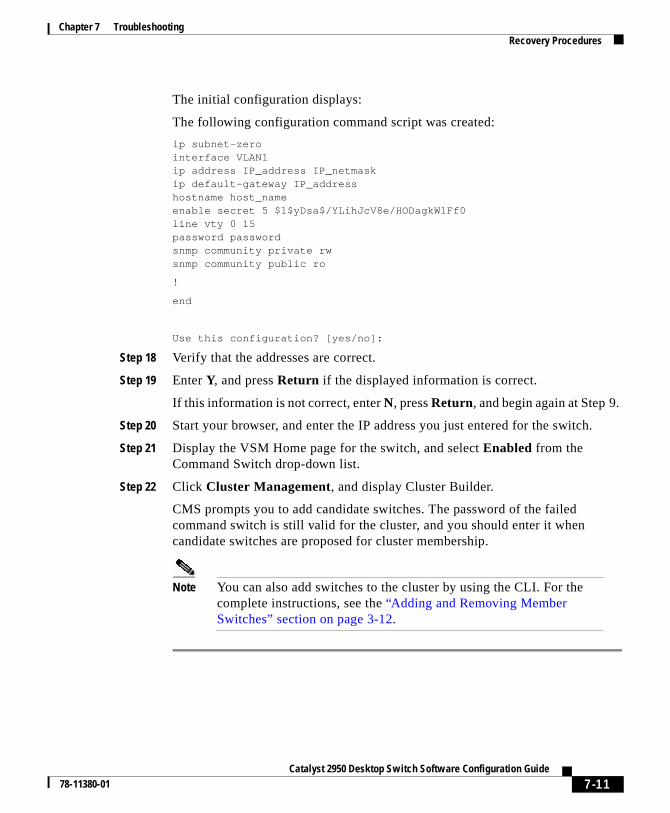
Chapter 7 TroubleshootingRecovery Procedures
The initial configuration displays:
The following configuration command script was created:
ip subnet-zerointerface VLAN1ip address IP_address IP_netmaskip default-gateway IP_addresshostname host_nameenable secret 5 $1$yDsa$/YLihJcV8e/HODagkW1Ff0line vty 0 15password passwordsnmp community private rwsnmp community public ro
!
end
Use this configuration? [yes/no]:
Step 18 Verify that the addresses are correct.
Step 19 Enter Y, and press Return if the displayed information is correct.
If this information is not correct, enter N, press Return, and begin again at Step 9.
Step 20 Start your browser, and enter the IP address you just entered for the switch.
Step 21 Display the VSM Home page for the switch, and select Enabled from theCommand Switch drop-down list.
Step 22 Click Cluster Management, and display Cluster Builder.
CMS prompts you to add candidate switches. The password of the failedcommand switch is still valid for the cluster, and you should enter it whencandidate switches are proposed for cluster membership.
Note You can also add switches to the cluster by using the CLI. For thecomplete instructions, see the “Adding and Removing MemberSwitches” section on page 3-12.
7-11Catalyst 2950 Desktop Switch Software Configuration Guide
78-11380-01
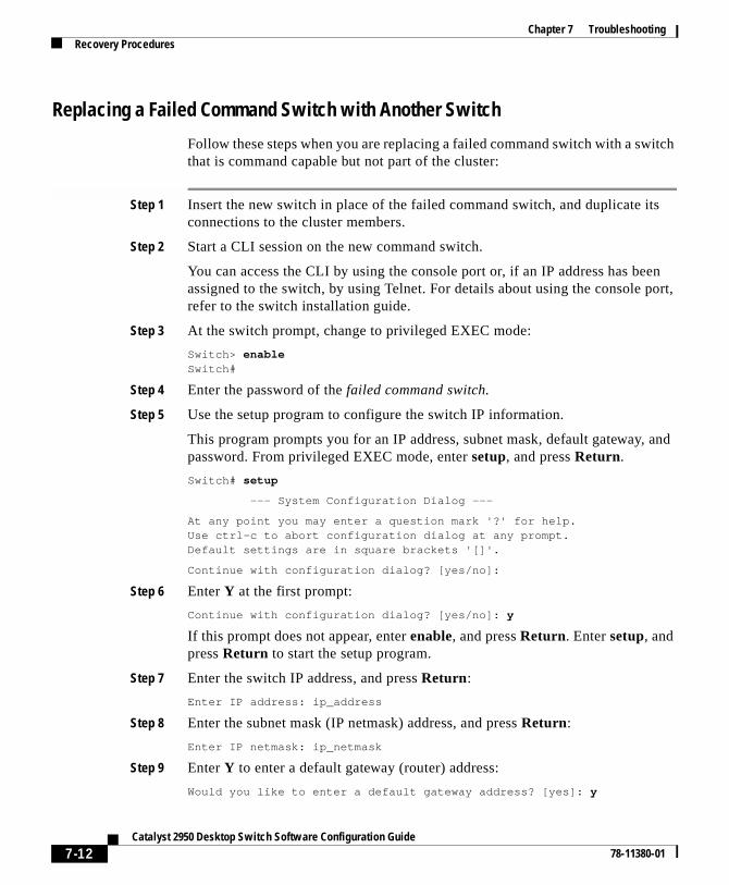
Chapter 7 TroubleshootingRecovery Procedures
Replacing a Failed Command Switch with Another Switch
Follow these steps when you are replacing a failed command switch with a switchthat is command capable but not part of the cluster:
Step 1 Insert the new switch in place of the failed command switch, and duplicate itsconnections to the cluster members.
Step 2 Start a CLI session on the new command switch.
You can access the CLI by using the console port or, if an IP address has beenassigned to the switch, by using Telnet. For details about using the console port,refer to the switch installation guide.
Step 3 At the switch prompt, change to privileged EXEC mode:
Switch> enableSwitch#
Step 4 Enter the password of the failed command switch.
Step 5 Use the setup program to configure the switch IP information.
This program prompts you for an IP address, subnet mask, default gateway, andpassword. From privileged EXEC mode, enter setup, and press Return.
Switch# setup
--- System Configuration Dialog ---
At any point you may enter a question mark '?' for help.Use ctrl-c to abort configuration dialog at any prompt.Default settings are in square brackets '[]'.
Continue with configuration dialog? [yes/no]:
Step 6 Enter Y at the first prompt:
Continue with configuration dialog? [yes/no]: y
If this prompt does not appear, enter enable, and press Return. Enter setup, andpress Return to start the setup program.
Step 7 Enter the switch IP address, and press Return:
Enter IP address: ip_address
Step 8 Enter the subnet mask (IP netmask) address, and press Return:
Enter IP netmask: ip_netmask
Step 9 Enter Y to enter a default gateway (router) address:
Would you like to enter a default gateway address? [yes]: y
7-12Catalyst 2950 Desktop Switch Software Configuration Guide
78-11380-01

Chapter 7 TroubleshootingRecovery Procedures
Step 10 Enter the IP address of the default gateway (router), and press Return:
Enter router IP address: IP_address
Step 11 Enter a host name, and press Return:
Enter host name: host_name
Step 12 Enter the password of the failed command switch again, and press Return:
Enter enable secret password: secret_password
Step 13 Enter a Telnet password, and press Return:
Would you like to configure a telnet password? [yes]: yEnter telnet password: password
The initial configuration displays:
The following configuration command script was created:
ip subnet-zerointerface VLAN1ip address IP_address IP_netmaskip default-gateway IP_addresshostname host_nameenable secret 5 $1$yDsa$/YLihJcV8e/HODagkW1Ff0line vty 0 15password passwordsnmp community private rwsnmp community public ro
!
end
Use this configuration? [yes/no]:
Step 14 Verify that the addresses are correct.
Step 15 Enter Y, and press Return if the displayed information is correct.
If this information is not correct, enter N, press Return, and begin again at Step 5.
Step 16 Start your browser, and enter the IP address you just entered for the switch.
Step 17 Click Cluster Manager Suite or Visual Switch Manager, and display ClusterBuilder.
It prompts you to add the candidate switches. The password of the failedcommand switch is still valid for the cluster. Enter it when candidate switches areproposed for cluster membership, and click OK.
7-13Catalyst 2950 Desktop Switch Software Configuration Guide
78-11380-01
Chapter 7 TroubleshootingRecovery Procedures
Note You can also add switches to the cluster by using the CLI. For thecomplete instructions, see the “Adding and Removing MemberSwitches” section on page 3-12.
Recovering from Lost Member ConnectivitySome configurations can prevent the command switch from maintaining contactwith member switches. If you are unable to maintain management contact with amember, and the member switch is forwarding packets normally, check for thefollowing port-configuration conflicts:
• Member switches cannot connect to the command switch through a port thatis defined as a network port. For information on the network port feature, seethe “Managing the System Date and Time” section on page 4-22.
• Member switches must connect to the command switch through a port thatbelongs to the same management VLAN. For more information, see the“Understanding Management VLAN Changes” section on page 3-4.
• Member switches connected to the command switch through a secured portcan lose connectivity if the port is disabled due to a security violation.Secured ports are described in the “Enabling Port Security” section onpage 4-58.
7-14Catalyst 2950 Desktop Switch Software Configuration Guide
78-11380-01

Catalyst 2950 Desktop Swi78-11380-01
A
P P E N D I X A System Error MessagesThis chapter describes the IOS system error messages for the Catalyst 2950switches. The system software sends these error messages to the console (and,optionally, to a logging server on another system) during operation. Not all systemerror messages indicate problems with your system. Some messages are purelyinformational, while others might help diagnose problems with communicationslines, internal hardware, or the system software.
This chapter contains the following sections:
• How to Read System Error Messages, page A-1
• Error Message Traceback Reports, page A-4
How to Read System Error MessagesSystem error messages begin with a percent sign (%) and are structured asfollows:
%FACILITY-SUBFACILITY-SEVERITY-MNEMONIC: Message-text
• FACILITY is a code consisting of two or more uppercase letters that indicatethe facility to which the message refers. A facility can be a hardware device,a protocol, or a module of the system software. Table A-1 lists the systemfacility codes.
A-1tch Software Configuration Guide

Appendix A System Error MessagesHow to Read System Error Messages
• SEVERITY is a single-digit code from 0 to 7 that reflects the severity of thecondition. The lower the number, the more serious the situation. Table A-2lists the message severity levels.
• MNEMONIC is a code that uniquely identifies the error message.
• Message-text is a text string describing the condition. This portion of themessage sometimes contains detailed information about the event, includingterminal port numbers, network addresses, or addresses that correspond tolocations in the system memory address space. Because the information inthese variable fields changes from message to message, it is represented here
Table A-1 Facility Codes
Code Facility
CMP Cluster Membership Protocol
ENVIRONMENT Environment
LINK Link
PORT SECURITY Port Security
RTD Runtime Diagnostic
STORM CONTROL Storm Control
Table A-2 Message Severity Levels
Severity Level Description
0 – emergency System is unusable.
1 – alert Immediate action required.
2 – critical Critical condition.
3 – error Error condition.
4 – warning Warning condition.
5 – notification Normal but significant condition.
6 – informational Informational message only.
7 – debugging Message that appears during debuggingonly.
A-2Catalyst 2950 Desktop Switch Software Configuration Guide
78-11380-01
Appendix A System Error MessagesHow to Read System Error Messages
by short strings enclosed in square brackets ([ ]). A decimal number, forexample, is represented as [dec]. Table A-3 lists the variable fields inmessages.
The following is a sample system error message:
%LINK-2-BADVCALL: Interface [chars], undefined entry point
Some error messages also indicate the card and slot reporting the error. Theseerror messages begin with a percent sign (%) and are structured as follows:
%CARD-SEVERITY-MSG:SLOT %FACILITY-SEVERITY-MNEMONIC:Message-text
CARD is a code that describes the type of card reporting the error.
MSG is a mnemonic that indicates this is a message. It is always shown as MSG.
SLOT indicates the slot number of the card reporting the error. It is shown asSLOT followed by a number. (For example, SLOT5.)
Table A-3 Representation of Variable Fields in Messages
Representation Type of Information
[dec] Decimal
[char] Single character
[chars] Character string
[hex] Hexadecimal integer
[inet] Internet address
A-3Catalyst 2950 Desktop Switch Software Configuration Guide
78-11380-01

Appendix A System Error MessagesError Message Traceback Reports
Error Message Traceback ReportsSome messages describe internal errors and contain traceback information. Thisinformation is very important and should be included when you report a problemto your technical support representative.
The following sample message includes traceback information:
-Process= "Exec", level= 0, pid= 17
-Traceback= 1A82 1AB4 6378 A072 1054 1860
Error Message and Recovery ProceduresThis section lists the switch system messages by facility. Within each facility, themessages are listed by severity levels 0 to 7: 0 is the highest severity level, and 7is the lowest severity level. Each message is followed by an explanation and arecommended action.
CMP MessagesThis section contains the Cluster Membership Protocol (CMP) error messages.
CMP-5-ADD: The Device is added to the cluster (ClusterName:[chars], CMDR IP Address [inet])
Explanation The message indicates the device is added to the cluster: [chars]is the cluster name, and [inet] is the internet address of the command switch.
Action No action is required.
A-4Catalyst 2950 Desktop Switch Software Configuration Guide
78-11380-01

Appendix A System Error MessagesError Message and Recovery Procedures
CMP-5-MEMBER_CONFIG_UPDATE: Received member configuration frommember [dec]
Explanation This message indicates that the command switch received amember configuration: [dec] is the member number.
Action No action is required.
CMP-5-REMOVE The Device is removed from the cluster (ClusterName:[chars])
Explanation The message indicates the device is removed from the cluster:[chars] is the cluster name.
Action No action is required.
Environment MessagesThis section contains the Environment error messages.
ENVIRONMENT-2-FAN_FAULT
Explanation This message indicates that an internal fan fault is detected.
Action Either check the switch itself or use the show env command todetermine if a fan on the switch has failed. The Catalyst 2950 switch canoperate normally with one failed fan. Replace the switch at your convenience.
ENVIRONMENT-2-OVER_TEMP
Explanation This message indicates that an overtemperature condition isdetected.
Action Use the show env command to check if an overtemperature conditionexists. If it does:
– Place the switch in an environment that is within 32 to 113°F (0 to 45°C).
– Make sure fan intake and exhaust areas are clear.
A-5Catalyst 2950 Desktop Switch Software Configuration Guide
78-11380-01

Appendix A System Error MessagesError Message and Recovery Procedures
– If a multiple-fan failure is causing the switch to overheat, replace theswitch.
Link MessagesThis section contains the Link error message.
LINK-4-ERROR [chars] is experiencing errors.
Explanation This messages indicates that excessive errors have occurred onthis interface: [char] is the interface.
Action Check for duplex mismatches between both ends of the link.
Port Security MessagesThis section contains the Port Security error message.
PORT_SECURITY-2-SECURITYREJECT
Explanation This message indicates that a packet with an unexpected MACsource address is received on a secure port.
Action Remove the station with the unexpected MAC address from the secureport, or add the MAC address to the secure address table of the secure port.
RTD MessagesThis section contains the Runtime Diagnostic (RTD) error messages.
RTD-1-ADDR_FLAP [chars] relearning [dec] addrs per min
Explanation Normally, MAC addresses are learned once on a port.Occasionally, when a switched network reconfigures, due to either manual orSTP reconfiguration, addresses learned on one port are relearned on a different
A-6Catalyst 2950 Desktop Switch Software Configuration Guide
78-11380-01

Appendix A System Error MessagesError Message and Recovery Procedures
port. However, if there is a port anywhere in the switched domain that islooped back to itself, addresses will jump back and forth between the real portand the port that is in the path to the looped back port. In this message, [chars]is the interface, and [dec] is the number of addresses being learnt.
Action Determine the real path (port) to the MAC address. Use debugethernet-controller addr to see the alternate path-port on which the addressis being learned. Go to the switch attached to that port. Note that show cdpneighbors is useful in determining the next switch. Repeat this procedure untilthe port is found that is receiving what it is transmitting, and remove that portfrom the network.
RTD-1-LINK_FLAP [chars] link down/up [dec] times per min
Explanation This message indicates that an excessive number of link down-upevents has been noticed on this interface: [chars] is the interface, and [dec] isthe number of times the link goes up and down. This might be the result ofreconfiguring the port, or it might indicate a faulty device at the other end ofthe connection.
Action If someone is reconfiguring the interface or device at the other side ofthe interface, ignore this message. However, if no one is manipulating theinterface or device at the other end of the interface, it is likely that the Ethernettransceiver at one end of the link is faulty and should be replaced.
Storm Control MessagesThis section contains the Storm Control error message.
STORM_CONTROL-2-SHUTDOWN
Explanation This messages indicates that excessive traffic has been detected ona port that has been configured to be shut down if a storm event is detected.
Action Once the source of the packet storm has been fixed, re-enable the portby using port-configuration commands.
A-7Catalyst 2950 Desktop Switch Software Configuration Guide
78-11380-01

Appendix A System Error MessagesError Message and Recovery Procedures
A-8Catalyst 2950 Desktop Switch Software Configuration Guide
78-11380-01

Catalyst 2950 Desktop S78-11380-01
I N D E X
A
AAA
configuring 4-107
managing 4-101
aaa accounting command 4-106
aaa authorization command 4-105
aaa authorization exec tacacs+ localcommand 4-106
aaa new-model command 4-104, 4-107
abbreviations
char, variable field A-3
chars, variable field A-3
dec, variable field A-3
hex, variable field A-3
inet, variable field A-3
accessing
CMS 2-2
command modes 2-25
member switches 5-6, 5-28
MIB files 2-35
MIB objects 2-34, 2-35
MIB variables 2-35
accounting in TACACS+ 4-102
adding
Ethernet VLAN to database 5-25
member switches to standby group 3-24
secure addresses 4-52, 4-54
static addresses 4-55, 4-57
switches to cluster 3-12
address
count, secure 4-60
resolution 4-47
security violations 4-59
see also addresses
addresses
dynamic
accelerated aging 4-83
aging time 4-50, 4-51
default aging 4-83
described 4-49
removing 4-52
MAC
adding secure 4-52
aging time 4-50
discovering 4-47, 4-50
tables, managing 4-49
IN-1witch Software Configuration Guide

Index
secure
adding 4-52, 4-54
described 4-49, 4-52
removing 4-55
static
adding 4-55, 4-57
configuring (EtherChannel) 4-57
described 4-49, 4-55
removing 4-58
Address Management window 4-50
Address Resolution Protocol (ARP)
see ARP table
address table
aging time, configuring 4-51
dynamic addresses, removing 4-52
MAC 4-49
secure addresses
adding 4-54
removing 4-55
static addresses
adding 4-57
removing 4-58
administrative information, displaying 3-33
advertisements, VTP 5-9
aggregation
enterprise workgroup 1-6
small to medium business workgroup 1-7
aging, accelerating 4-83
aging time, changing address 4-50, 4-51
IN-2Catalyst 2950 Desktop Switch Software Configuratio
alarms group, in RMON 2-38
allowed-VLAN list 5-34
AppleTalk Remote Access (ARA) 4-105
Apply button 2-4
ARP table
address resolution 4-47
illustrated 4-48
managing 4-47
authentication, enabling NTP 4-26
authentication in TACACS+ 4-102
authorization in TACACS+ 4-102
autonegotiation
connecting to devices without 3-41
mismatches 7-1
B
bandwidth, graphing 2-19
BPDU message interval 4-92
broadcast client mode, configuring 4-26
broadcast messages, configuring for 4-26
broadcast storm control
disabling 4-21
enabling 4-18, 4-20
broadcast traffic and protected ports 4-101
buttons, CMS window 2-4
bytes, graphing 6-2
n Guide78-11380-01

Index
C
C2900/C3500 traps 3-63, 4-45
cabling, redundant 3-17
Cancel button 2-4
candidates
adding 3-12
automatically discovering 3-6
changing management VLAN for 3-37
displaying all 3-14
requirements 3-3
suggested 3-6
why not added 3-13
Caution described xvii
caveats
password and privilege level 3-11
CDP
configuring 4-62, 4-63
disabling for routing device 4-67, 4-68
discovering candidates with 3-6
Cisco Discovery Protocol
see CDP
Cisco Systems access page 3-29
CiscoWorks, as an example of CMS 2-36
Class of Service
see CoS
CLI
accessing 1-5
command modes 2-25
Catalyst 2950 78-11380-01
error messages 2-31
managing cluster members with 2-29
using 2-24
client mode, VTP 5-8
Cluster Builder
changing the polling interval 3-31
device and link icons 2-7
illustrated 3-13
interface 2-5
label meanings 2-9
menu options 2-7
overview 1-5
pop-up menus 2-11, 2-12
saving configuration changes 3-33
starting 2-20
toolbar icons 2-6
using 2-9
Cluster management described 3-1
Cluster Management Suite
see CMS
Cluster Management Suite (CMS) 2-35
Cluster Manager
menu options 2-15
overview 1-4
pop-up menus 2-17, 2-18
toolbar icons 2-19
using 2-14
IN-3Desktop Switch Software Configuration Guide

Index
clusters
accessing 3-5
adding switches to 3-12, 3-14
configuring 3-5, 3-8
creating 2-9
creating performance graphs 6-1
described 3-1, 5-4
disqualification code 3-13
host name changes 3-10
inventory, displaying 3-33
management tasks 3-27
management VLAN, changing 3-35
managing 2-29, 2-37, 3-1
password changes 3-11
planning 3-2
redundancy 3-2, 3-17
removing switches from 3-12, 3-14
settings, configuring initial 3-30
see also candidates, command switch,member switches, standby groups
cluster setup command 3-14
cluster tree 2-19
Cluster View
device and link icons 2-7
device menu options 2-14
displaying 3-13
interface 2-5
menu options 2-7
overview 1-5
toolbar icons 2-6
IN-4Catalyst 2950 Desktop Switch Software Configuratio
using 2-13
CMS 2-35
accessing 2-2, 3-28
overview 1-4
privilege level 2-28
using 2-3
windows, using 2-3
colors
devices in CMS 2-9
command-line error messages 2-31
command-line interface
see CLI
command modes 2-25, 2-26
commands
? 2-30
aaa accounting 4-106
aaa authorization 4-105
aaa authorization exec tacacs+ local 4-106
abbreviating 2-30
cluster setup 3-14
copy running-config startup-config 2-34
default 2-31
dir flash 2-33
help 2-30
list of available 2-27, 2-30
name 3-22
no 2-31
preempt 3-22
rcommand 2-29
n Guide78-11380-01

Index
redisplaying 2-30
redundancy-enable 3-22
resetting to defaults 2-31
show cluster candidates 3-14
show cluster members 2-29, 3-14
spanning-tree root guard 4-99
stp-list 4-80
undoing 2-31
command switch
and management 1-5
and managing with SNMP 2-37
configuration conflicts 7-14
defined 1-3, 3-1
enabling 3-5, 4-10
privilege levels 2-29
recovery
from failure 3-19, 7-8
from failure without HSRP 3-19
from lost member connectivity 7-14
redundant (standby) 3-17
removing from standby group 3-25
replacing
with another switch 7-12
with cluster member 7-9
requirements 3-3
standby 3-17, 3-18, 3-20
see also candidates, member switches
command variables, listing 2-30
community strings
Catalyst 2950 78-11380-01
added to new members 3-10
configuring 3-10, 3-60, 4-42
SNMP 2-37, 3-10
compatibility
cluster 3-2
feature 4-2
config trap 3-63, 4-45
configuration
changes
saving 3-33
conflicts, managing 4-2, 7-14
default VLAN 5-21
files, saving to an external server 2-33
guidelines
port 3-41
VLANs 5-20
VTP 5-10
VTP version 5-11
saving to Flash memory 2-34
VTP, default 5-12
see also configuring
configuring
802.1p class of service 5-37
AAA 4-107
aging time 4-51
broadcast messages 4-26
broadcast storm control 4-19
CDP 4-62, 4-63
clusters 3-5, 3-8
IN-5Desktop Switch Software Configuration Guide

Index
cluster settings, initial 3-30
community strings 3-10, 3-60, 4-42
date and time 4-22
daylight saving time 4-23
DNS 4-39
duplex 3-38, 3-49
flooding controls 4-18
flow control 3-49
hello time 4-92
hops 4-64
HSRP groups 3-22
IP information 4-26
load sharing 5-45, 5-48
login authentication 4-104
management VLAN 3-37
multicast router port 4-79
native VLANs 5-36
NTP 4-24
passwords 2-27
Port Fast 3-38
ports 3-42
multiple mixed 3-43
protected port 4-100
through Cluster Manager 2-17, 3-38
through VSM 2-21
privilege levels 2-27
redundant clusters 3-17
RMON groups 2-38
SNMP 3-59, 4-41
IN-6Catalyst 2950 Desktop Switch Software Configuratio
speed 3-38, 3-41, 3-49
standalone switches 4-9
standby group 3-22
standby groups 3-19, 3-22
static addresses (EtherChannel) 4-57
STP 4-80
path costs 5-48
port priorities 5-45
root guard 4-98, 4-99
switches
member 2-29
overview 4-1
standalone 4-9
TACACS+ 4-101
trap managers 3-63, 4-44
trunk port 5-31
trunks 5-30, 5-33
VLANs 5-1, 5-5, 5-20, 5-24
voice ports 4-108
VTP 5-10, 5-12
VTP client mode 5-15
VTP server mode 5-14
VTP transparent mode 5-6, 5-16
configuring a multicast router port 4-76
conflicts
configuration 4-2, 7-14
upgrade 3-55
consistency checks in VTP version 2 5-10
conventions
n Guide78-11380-01

Index
command xvi
for examples xvi
Note and Caution xvii
text xvi
copy running-config startup-configcommand 2-34
CoS 3-39
configuring 5-37
configuring priority queues 5-42
defining 5-39
D
database, VTP 5-19, 5-24
date, setting 4-22
daylight saving time 4-23
default configuration
VLANs 5-21
VTP 5-12
defaults, resetting to 2-31
default settings, changing 4-3
deleting VLAN from database 5-27
deployment examples 1-6
destination-based forwarding 4-14
destination-based port groups 4-12, 4-57
device arrangement 3-32
device pop-up menu 2-18
DHCP 4-29
configuring
DHCP server 4-32
Catalyst 2950 78-11380-01
DNS 4-33
example 4-37
relay device 4-34
TFTP server 4-33
dir flash command 2-33
disabling
broadcast storm control 4-21
port security 4-62
SNMP 4-42
SNMP agent 3-60
STP 4-83, 4-84
Switch Port Analyzer (SPAN) 4-18
trunking on a port 5-34
trunk port 5-34
VTP 5-16
VTP version 2 5-18
disqualification code 3-13
DNS
configuring 4-39
described 4-39
enabling 4-41
documentation, related xvii
domain name
described 4-39
specifying 4-39, 4-40, 5-10
Domain Name System server
see DNS
domains for VLAN management 5-7
DTP 5-33
IN-7Desktop Switch Software Configuration Guide

Index
duplex
configuration guidelines 3-41
configuring 3-49
dynamic addresses
see addresses
Dynamic Host Configuration Protocol
see DHCP
Dynamic Trunk Protocol (DTP) 5-33
E
egress port scheduling 5-38
eligible switches 3-20
enable password
see passwords
enable secret password
see passwords
enabling
broadcast storm control 4-18, 4-20
command switch 3-5, 4-10
DNS 4-41
HSRP 3-22
NTP authentication 4-26
Port Fast 4-95, 4-97
port security 4-58, 4-61
SNMP 4-42
SNMP agent 3-60
STP Port Fast 4-95, 4-97
Switch Port Analyzer (SPAN) 4-15, 4-17
IN-8Catalyst 2950 Desktop Switch Software Configuratio
traps 3-63
UplinkFast 4-87
VTP version 2 5-17
encapsulation 5-37
enterprise workgroup aggregation 1-6
error messages 2-31
errors, graphing 6-2
EtherChannel port groups
configuring static address for 4-57
creating 4-11, 4-15
Ethernet VLAN
adding to database 5-25
defaults and ranges 5-21
modifying 5-26
events group, in RMON 2-38
examples
conventions for xvi
deployment 1-6
extended discovery 4-63
F
facility codes A-1
Fast EtherChannel port groups, creating 4-11
Fast Ethernet trunks 5-29
FDDI-Net VLAN defaults and ranges 5-22
FDDI VLAN defaults and ranges 5-21
n Guide78-11380-01

Index
features
configuration conflicts between 2-25
default settings 4-2
incompatible 4-2
IOS 1-2
Flash memory, files in 2-33, 2-34
flooding controls
configuring 4-18
illustrated 4-19
flow control, configuring 3-49
forwarding
controlling (SNMP) 2-37
delay 4-89, 4-93
port groups 4-12
restrictions 4-14
source-based, illustrated 4-12
see also broadcast storm control
forwarding window, static address 4-55
FTP, accessing MIB files with 2-35
G
get-next-request operation 2-36, 2-37
get-request operation 2-36, 2-37
get-response operation 2-37
Gigabit Ethernet
ports, configuring flow control on 3-50
settings 3-42
trunks 5-29
Catalyst 2950 78-11380-01
global configuration mode 2-26
graphing bytes 6-2
graphs
bandwidth 2-19
link utilization 6-1
percent utilization 6-2
poll result 2-36
H
hardware
supported switches 1-3
hello BPDU interval 4-92
hello time
changing 4-92
defined 4-89
help, getting 2-20, 2-30
Help button 2-4
history group, in RMON 2-38
home page, VSM 4-10
hops, configuring 4-64
host names
abbreviations appended to 3-21
changes to 3-10
changing 3-32
to address mappings 4-39
Hot Standby Router Protocol
see HSRP
IN-9Desktop Switch Software Configuration Guide

Index
HSRP 3-17, 3-22
see also standby group
I
icons
Cluster Builder 2-7
Cluster Manager toolbar 2-19
Cluster View 2-7
IEEE 802.1Q
configuration considerations 5-30
interaction with other features 5-30
native VLAN for untagged traffic 5-36
overview 5-29
IEEE 802.1Q trunks 5-30
IGMP snooping 4-64
configuring a multicast router port 4-69
disabling 4-66
enabling 4-66
joining a multicast group 4-70
leaving a multicast group 4-76
Immediate Leave 4-68
defined 4-68
disable 4-69
enable 4-69
ingress port scheduling 5-37
interface configuration mode 2-27
interfaces
Cluster Builder 2-5
IN-10Catalyst 2950 Desktop Switch Software Configuratio
Cluster View 2-5
IOS supported 1-4
Internet Group Management Protocol
see IGMP snooping
inventory, displaying 3-33
IOS
see software and upgrading 3-2
IP addresses
and admittance to standby groups 3-20
candidate 3-4
discovering 4-47
management VLAN 3-4
point of access 3-1
in redundant clusters 3-18
removing 4-29
see also IP information
IP information
assigning 4-28
configuring 4-26
displaying 3-33
removing 4-29
IP Management window 4-27
IP setup program 7-10, 7-12
IPX server time-out, and Port Fast 4-95
L
LEDs, monitoring 3-39, 3-41
line configuration mode 2-27
n Guide78-11380-01

Index
link
graph, illustrated 6-3
utilization graphs 6-1
link icons, Cluster Builder and ClusterView 2-7
link information, displaying 3-34
load sharing
STP, described 5-43
using STP path cost 5-46
using STP port priorities 5-44
location of displayed switches 3-32
location of switches, displaying 3-33
login authentication, configuring 4-104
M
MAC addresses
adding secure 4-52
aging time 4-50
discovering 4-47, 4-50
MAC address tables, managing 4-49
management interface features 2-1
management options 1-4
management VLAN
changes, understanding 3-4
changing 3-4, 3-34
configuring 3-37
described 5-4
IP address 3-4
Management VLAN window 3-36
Catalyst 2950 78-11380-01
map
see also network map
membership mode, VLAN port 5-3
member switches
accessing 5-6, 5-28
adding
with Cluster Builder 3-12
from the command line 3-14
to standby group 3-24
assigning host names to 3-10
defined 1-3
displaying inventory of 3-33
managing 2-29
order 3-31
passwords, inherited 3-11
recovering from lost connectivity 7-14
removing
from standby group 3-25
upgrading 3-57, 3-58
see also candidates, command switch
menu options
Cluster Builder 2-7
Cluster Manager 2-15
Cluster View 2-7, 2-14
VSM 2-22
see also pop-up menus
messages, CLI error 2-31
IN-11Desktop Switch Software Configuration Guide

Index
message severity levels
description A-2
table A-2
MIB files, accessing 2-35
MIB objects, accessing 2-34
MIB variables, accessing 2-35
mismatches, autonegotiation 7-1
mnemonic code A-2
Mode button 2-21, 3-39, 3-40
model numbers, displaying 3-33
modes
command 2-25
VLAN port membership 5-3
VTP
see VTP modes
Modify button 2-4
modules
installed, displaying 3-33
monitoring
devices with Cluster Manager 2-14
LEDs 3-39, 3-41
ports 3-38, 4-15
traffic 4-15
VTP 5-18
multicast groups
joining 4-70
leaving 4-76
multicast traffic, and protected ports 4-101
IN-12Catalyst 2950 Desktop Switch Software Configuratio
N
name command 3-22
NAT 3-9
native VLANs 5-36
NCPs 4-105
Network Address Translation
see NAT
Network Control Protocols (NCPs) 4-105
network map
creating 3-30
saving 3-30
Network Time Protocol. See NTP
no commands, using 2-31
Note described xvii
NTP
authentication, enabling 4-26
broadcast-client mode 4-26
client 4-25
configuring 4-24
described 4-24
illustrated 4-25
O
OK button 2-4
online help, displaying 2-4
order, switch 3-31
n Guide78-11380-01

Index
P
packets
graphing 6-2
parallel links 5-43
passwords
candidate switch 3-6
changing 4-11
community strings 4-42
member switch, inherited 3-11
recovery of 3-19, 7-6
setting 2-27
TACACS+ server 4-102
VTP domain 5-11
path cost 4-96, 4-97, 5-46
polling interval 3-31
poll results, graphing 2-36
pop-up menus
Cluster Builder candidate 2-11
Cluster Builder link 2-12
Cluster Builder member 2-12
Cluster Manager device 2-18
Cluster Manager port 2-17
port-connection information, displaying 3-34
Port Fast
configuring 3-38
enabling 4-95, 4-97
port groups
and trunks 5-31
Catalyst 2950 78-11380-01
configuring 3-38
configuring static addresses(EtherChannel) 4-57
creating EtherChannel 4-11, 4-15
destination-based 4-12, 4-57
forwarding 4-12
restrictions on forwarding 4-14
source-based 4-12, 4-57
see also ports
port membership modes, VLAN 5-3
port-monitoring conflicts with trunks 5-30
port pop-up menu 2-17
ports
configuration guidelines 3-41
configuring
through Cluster Manager 3-38, 3-42
multiple mixed 3-43
with port pop-up menu 2-17
protected ports 4-100
trunk 5-31
voice 4-108
through VSM 2-21
Gigabit Ethernet
configuring flow control on 3-50
monitoring 3-38, 5-30
priority 4-98, 5-37, 5-44
protected ports 4-100
secure 4-60, 5-31
IN-13Desktop Switch Software Configuration Guide
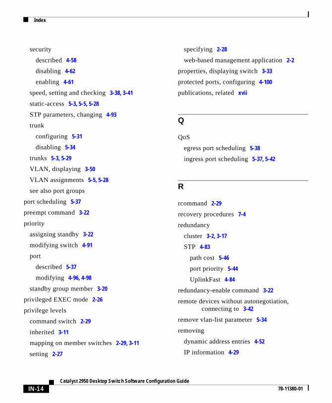
Index
security
described 4-58
disabling 4-62
enabling 4-61
speed, setting and checking 3-38, 3-41
static-access 5-3, 5-5, 5-28
STP parameters, changing 4-93
trunk
configuring 5-31
disabling 5-34
trunks 5-3, 5-29
VLAN, displaying 3-50
VLAN assignments 5-5, 5-28
see also port groups
port scheduling 5-37
preempt command 3-22
priority
assigning standby 3-22
modifying switch 4-91
port
described 5-37
modifying 4-96, 4-98
standby group member 3-20
privileged EXEC mode 2-26
privilege levels
command switch 2-29
inherited 3-11
mapping on member switches 2-29, 3-11
setting 2-27
IN-14Catalyst 2950 Desktop Switch Software Configuratio
specifying 2-28
web-based management application 2-2
properties, displaying switch 3-33
protected ports, configuring 4-100
publications, related xvii
Q
QoS
egress port scheduling 5-38
ingress port scheduling 5-37, 5-42
R
rcommand 2-29
recovery procedures 7-4
redundancy
cluster 3-2, 3-17
STP 4-83
path cost 5-46
port priority 5-44
UplinkFast 4-84
redundancy-enable command 3-22
remote devices without autonegotiation,connecting to 3-42
remove vlan-list parameter 5-34
removing
dynamic address entries 4-52
IP information 4-29
n Guide78-11380-01

Index
secure addresses 4-55
standby group from network 3-26
static addresses 4-55, 4-58
switches from a standby group 3-25
Requested and Actual settings 3-41
RMON
configuring 4-108
supported groups 2-38
root guard 4-98, 4-99
S
saving
cluster configuration 3-33
network map 3-30
secure address count 4-60
secure addresses
adding 4-52, 4-54
described 4-52
removing 4-55
secure ports
address-security violations 4-59
disabling 4-62
enabling 4-58, 4-61
maximum secure address count 4-60
and trunks 5-31
security
port 4-58
TACACS+ 4-102
Catalyst 2950 78-11380-01
violations, address 4-59
Serial Line Internet Protocol (SLIP) 4-105
serial numbers, displaying 3-33
server, domain name 4-41
server mode, VTP 5-8
server time-out, and Port Fast 4-95
set-request operation 2-36, 2-37
setting
see configuring
settings
cluster, initial 3-30
default, changing 4-3
duplex 3-38, 3-41, 3-49
multiple mixed port 3-43
port, monitoring 3-39
Requested and Actual 3-41
speed 3-49
user, changing 3-31
setup program 7-10, 7-12
severity levels
description A-2
table A-2
show cluster candidates command 3-14
show cluster members command 2-29, 3-14
SLIP 4-105
small to medium-sized business workgroupaggregation 1-7
SNMP 3-59
accessing MIB variables with 2-35
agent 3-60
IN-15Desktop Switch Software Configuration Guide

Index
community strings
changes to 3-10
configuring 3-60, 4-42
configuring for
cluster members 3-59
single switches 4-41
disabling 3-60
enabling 3-60
enabling and disabling 4-42
management, using 2-34
managing clusters with 2-37
network management platforms 1-5
RMON groups 2-38
trap managers, configuring 3-63, 4-44
trap types 3-63, 3-64, 4-45
SNMP Configuration window, displaying 2-20
SNMP Manager, illustrated 3-61, 3-62
software
recovery procedures 7-5
reloading 3-59
requirements for
changing management VLAN 3-36
joining standby groups 3-20
to support clustering 3-2
upgrading switch 3-51
version numbers, displaying 3-33
see also upgrading
Software Upgrade window 2-20
source-based forwarding 4-14
IN-16Catalyst 2950 Desktop Switch Software Configuratio
source-based port groups 4-12, 4-57
SPAN
described 4-15
disabling 4-18
enabling 4-17
ports, restrictions 4-2
Spanning-Tree Protocol
see STP
spanning-tree rootguard command 4-99
speed, setting 3-38, 3-41, 3-49
splash screen, displaying at startup 3-31
standalone switches
configuring 4-9
Standby Command Configurationwindow 3-20, 3-21
standby command switch requirements 3-20
standby group
adding switches to 3-24
configuration guidelines 3-22
configuring 3-17, 3-19, 3-22
priority, configuring 3-20
removing from network 3-26
removing switches from 3-25
startup configuration, copying to PC orserver 3-52
static-access ports
assigning to VLAN 5-5, 5-28
described 5-5
VLAN membership combinations 5-3
static addresses
n Guide78-11380-01

Index
adding 4-55, 4-57
configuring for EtherChannel portgroups 4-57
described 4-49, 4-55
removing 4-58
see also static address
static address forwarding restrictions 4-14
static address forwarding window 4-55
statistics, VTP 5-18
statistics group, in RMON 2-38
status, monitoring port 3-38
STP
BPDU message interval 4-92
configuring 4-80
disabling 4-83, 4-84
forwarding delay timer 4-93
hello BPDU interval 4-92
implementation type 4-90
load sharing
overview 5-43
using path costs 5-46
using port priorities 5-44
number of supported instances 5-2
parameters 4-80
path cost
changing 4-97
configuring 5-48
Port Fast
enabling 4-95, 4-97
port grouping parameters 4-13, 5-31
Catalyst 2950 78-11380-01
port parameters, changing 4-93
port priority 4-98, 5-45
redundant connectivity 4-83
redundant links with UplinkFast 4-84
root guard 4-98, 4-99
supported number of spanning-treeinstances 4-80
switch priority 4-91
UplinkFast 4-84, 4-87
VLAN parameters described 4-87
stp-list parameter 4-80
Sun Microsystems
URL for required plug-in 4-9
switches
see candidates, command switch, memberswitches
Switch Port Analyzer (SPAN)
disabling 4-18
enabling 4-15, 4-17
illustrated 4-16
switchport command 5-33
system date and time 4-22
T
tables
message severity levels A-2
variable fields A-3
TACACS+
AAA accounting commands 4-106
IN-17Desktop Switch Software Configuration Guide

Index
AAA authorization commands 4-105
configuring 4-101
initializing 4-104
server, creating 4-103
tacacs-server host command 4-103
tacacs-server retransmit command 4-103, 4-107
tacacs-server timeout command 4-103
Telnet, starting from browser 2-33
TFTP server, upgrading multiple switcheswith 3-52
time
daylight saving 4-23
setting 4-22
time zones 4-22
TLV 5-10
Token Ring VLANs
overview 5-20
TrBRF 5-10, 5-22
TrCRF 5-10, 5-23
toolbar icons
Cluster Builder 2-6
Cluster Manager 2-19
Cluster View 2-6
topology 3-30
see also network map
traceback reports A-4
traffic
forwarding, and protected ports 4-100
monitoring 4-15
reducing flooded 4-18
IN-18Catalyst 2950 Desktop Switch Software Configuratio
transmit queue 5-38
transparent mode, VTP 5-8, 5-16
trap managers
adding 4-44, 4-47
configuring 3-63, 4-44
supported 3-63
traps 2-37, 3-63, 4-45
TrBRF VLAN defaults and ranges 5-22
TrCRF VLAN defaults and ranges 5-23
troubleshooting
IOS 7-1
with CiscoWorks2000 2-36
trunk ports
configuring 5-31
disabling 5-34
trunks
allowed-VLAN list 5-34
configuration conflicts 5-30
configuring 5-33
disabling 5-34
IEEE 802.1Q 5-30
interacting with other features 5-30
load sharing using
STP path costs 5-46
STP port priorities 5-44
native VLAN for untagged traffic 5-36
overview 5-29
parallel 5-46
VLAN, overview 5-29
n Guide78-11380-01

Index
VLAN membership combinations 5-4
TTY traps 3-63, 4-45
U
UDLD 4-100
unicast traffic, and protected ports 4-101
UniDirectional Link Detection
see UDLD
Unrecognized Type-Length-Value (TLV)support 5-10
upgrading
1900 and 2820 member switches 3-58
2900, 2950, and 3500 member switches 3-57
conflicts while 3-55
multiple switches with TFTP 3-52
software
with CLI 3-55
with VSM 3-59
standalone switches 3-55
switch software 3-51
UplinkFast
enabling 4-87
redundant links 4-84
user EXEC mode 2-26
user settings 3-31
User Settings window, displaying 2-20
utilization graphs 6-1
Catalyst 2950 78-11380-01
V
variable fields
definition A-3
table A-3
version-dependent transparent mode 5-10
virtual IP address
HSRP 3-18
standby group member 3-21
see also IP addresses
VLAN
port membership modes 5-3
trunks, overview 5-29
VLAN database mode 2-26
VLAN ID, discovering 4-47, 4-50
VLAN membership
combinations 5-3
described 5-4
displaying 3-50
modes 5-3
port group parameters 4-13
traps 3-63, 4-45
see also dynamic ports VLAN membership
VLAN membership combinations 5-3
VLAN Membership window 2-20
VLANs
802.1Q considerations 5-30
adding to database 5-25
aging dynamic addresses 4-83
IN-19Desktop Switch Software Configuration Guide

Index
allowed on trunk 5-34
changing 5-26
configuration guidelines 5-20
configuring 5-1, 5-5, 5-24
default configuration 5-21
deleting from database 5-27
described 5-1
displaying 3-50
illustrated 5-2
MAC addresses 4-50
modifying 5-26
native, configuring 5-36
number supported 5-2
static-access ports 5-5, 5-26, 5-28
STP parameters, changing 4-87
supported 5-2
Token Ring 5-20
trunks configured with other features 5-30
see also trunks
VTP database and 5-19
VTP modes 5-8
See also management VLAN
voice ports, configuring 4-108
VSM
accessing 4-9
conflicts while upgrading 3-55
home page 2-21, 4-10
menu options 2-22
overview 1-4
IN-20Catalyst 2950 Desktop Switch Software Configuratio
privilege level 2-28
using 2-20
VTP
advertisements 5-9
configuration guidelines 5-10
configuring 5-12
consistency checks 5-10
database 5-19, 5-24
default configuration 5-12
described 5-6
disabling 5-16
domain names 5-10
domains 5-7
modes
client 5-8
configuring 5-15
server 5-8, 5-14
transitions 5-8
transparent 5-6, 5-8, 5-16
monitoring 5-18
statistics 5-18
Token Ring support 5-10
transparent mode, configuring 5-16
traps 3-63, 4-45
using 5-6
version, determining 5-11
version 1 5-10
n Guide78-11380-01

Index
version 2
configuration guidelines 5-11
disabling 5-18
enabling 5-17
overview 5-10
VLAN parameters 5-19
W
web-based management, using 2-2
Weighted Round Robin
see WRR
WRR
configuring 5-43
defining 5-39
description 5-39
X
Xmodem protocol 7-5
Catalyst 2950 78-11380-01
IN-21Desktop Switch Software Configuration Guide

Index
IN-22Catalyst 2950 Desktop Switch Software Configuratio
n Guide78-11380-01