Catalog Slimline
28
LOW PROFILE EQUALIZING LEG ® BEARINGS LE G ® SlimLine
Transcript of Catalog Slimline

7/25/2019 Catalog Slimline
http://slidepdf.com/reader/full/catalog-slimline 1/27
LOW PROFILE EQUAL IZ ING LEG ® BEARINGS
LEG®
SlimLine

7/25/2019 Catalog Slimline
http://slidepdf.com/reader/full/catalog-slimline 2/27
TABLE OF CONTENTS
INTRODUCTION . . . . . . . . . . .3
LEG ADVANTAGES . . . . . . . . . .5
GENERAL DESCRIPTION . . . .6
BEARING HOUSING . . . . . . .8
LEG PERFORMANCE . . . . . . .9
BEARING SELECTION
6-PAD BEARINGS . . . . . .10
8-PAD BEARINGS . . . . . .14
11-PAD-BEARINGS . . . . .18
INSTRUMENTATION . . . . . . .22
BABBITT
TEMPERATURE . . . . . . . . . .23
NOTES ON SELECTING . . . . .24
GENERAL INFORMATION . . .25
LEG JOURNAL BEARINGS . . .27

7/25/2019 Catalog Slimline
http://slidepdf.com/reader/full/catalog-slimline 3/27
Kingsbury has adapted its Leading Edge Groove lubricationtechnology to a new low-profile design.The new LEG® SlimLine is
a fully equalizing thrust bearing with all the attributes of our
standard LEG product,but in a thinner profile.
In this new model, each pad is designed to carry an equal
amount of thrust load. Leveling plates on the back of the bearing
reduce the chance of one pad being more highly loaded than
another. The leveling plates, combined with a spherical pad
support, also ensure that the thrust bearing face becomes perfectly aligned with the rotating thrust collar.
Important design features, such as Kingsbury’s 360º pad pivot
arrangement as well as conservative load ratings, allow you to con-
fidently specify the LEG SlimLine in even the toughest applications.
Perfect for retrofit, the LEG SlimLine may be specified for one-to-
one replacement for tapered land or low-profile non-equalizing
tilt-pad bearings in existing applications, reducing downtime and
improving overall performance. ISO standards are used for alldimensional tolerances.
For engineering assistance on OEM or aftermarket applications,
contact our offices in Philadelphia, PA. Please see the back cover of
this catalog for contact details.
3

7/25/2019 Catalog Slimline
http://slidepdf.com/reader/full/catalog-slimline 4/27

7/25/2019 Catalog Slimline
http://slidepdf.com/reader/full/catalog-slimline 5/27
5
THE ADVANTAGESOF LEGTECHNOLOGYLeading Edge Groove
(LEG) technology, introducedby Kingsbury in 1984,
has revolutionized the world
of thrust bearings. The cre-
ation of these new thrust
bearings has made it possible
for the world’s leading equip-
ment manufacturers to simul-
taneously increase bearing
capacity, reduce friction
losses and hold babbitt tem-
peratures within acceptablelimits. When compared to a
standard thrust bearing, the
advanced design LEG
SlimLine bearing can:
• Reduce operating tempera-
tures at the 75/75 location
by 8˚ to 27˚ C, depending
on shaft speed.
• Provide a load carrying
capacity increase of 15-
20%, based on that tem-
perature reduction.
• Operate at oil flow rates as
much as 60% lower, with
an accompanying reduc-
tion in friction losses
of 40%.

7/25/2019 Catalog Slimline
http://slidepdf.com/reader/full/catalog-slimline 6/27
6
While the general arrange-
ment of the LEG SlimLine
appears to be very familiar,
certain key features make it
superior to the morecommon tilt-pad bearings in
use today.
Pads All LEG SlimL ine bearing
pads are provided with
Leading Edge Groove (LEG)
lubrication grooves to
improve oil flow, reduce
power loss, reduce friction
and reduce pad temperature.
Bearings are designed to the
proper rotation direction
rather than the “all-in-one”
style which accommodates
either CW or CCW rotation.
This feature means that per-
formance is assured accord-
ing to design tolerances
rather than on averages.
Standard materials of con-
struction of pad body are low
carbon steel with high tin
content babbitt face,
although material selection
can be engineered to meet
unusual applications.
The low-profile equalizing
LEG SlimLine utilizes a dis-
tinctive raised “button” onthe back of the pad to allow
full 360º pivot, rather than
the more familiar strip which
allows pad tilt in only one
direction. Pad buttons are
made of carbon tool steel,
heat treated to 52 to 57
Rockwell C to ensure no
flattening of the sphere.
Kingsbury tests indicate thatthis feature lowers the spread
of temperatures from pad to
pad.
GENERAL DESCRIPTION

7/25/2019 Catalog Slimline
http://slidepdf.com/reader/full/catalog-slimline 7/27
Leveling PlatesLeveling plates are built in to
the carrier ring assembly, to
allow even distribution of
load on each pad surface.
The unique design of
7
Kingsbury’s low-profile level-
ing plates permits installation
of the bearing in an extreme-
ly shallow envelope, allow-
ing for retrofits in spaces where only a non-equalizing
bearing could fit previously.
Carrier RingsCarrier rings are constructed
to exacting ISO tolerances
and are normally provided
in halves to allow simple
installation in tough-to-reach
applications. Standard materi-
al of construction is low
carbon steel.
Pad RetentionPads are held in place by a
retaining fastener which can
be removed easily to facili-
tate service or replacement.
LubricationLubrication ports from the
carrier ring provide oil
directly to the bearing pads,
through individual oil feed
tubes, to ensure even pres-
sure and distribution. The oil
feed tubes are designed so
that the pad is free to pivot.
This ensures that all oil is feddirectly to the leading edge
of the pad face.
7/25/2019 Catalog Slimline
http://slidepdf.com/reader/full/catalog-slimline 8/27
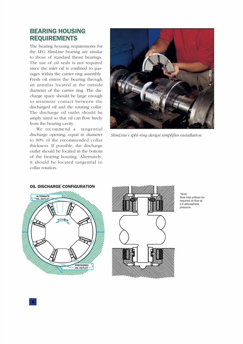
BEARING HOUSINGREQUIREMENTSThe bearing housing requirements for
the LEG SlimLine bearing are similar
to those of standard thrust bearings.
The use of oil seals is not required
since the inlet oil is confined to pas-
sages within the carrier ring assembly.
Fresh oil enters the bearing through
an annulus located at the outside
diameter of the carrier ring. The dis-
charge space should be large enough
to minimize contact between the
discharged oil and the rotating collar.
The discharge oil outlet should be
amply sized so that oil can flow freely
from the bearing cavity.
We recommend a tangential
discharge opening, equal in diameter
to 80% of the recommended collar
thickness. If possible, the discharge
outlet should be located in the bottom
of the bearing housing. Alternately,
it should be located tangential to
collar rotation.
8
ALTERNATE
OIL OUTLET
PREFERRED
OIL OUTLET
OIL DISCHARGE CONFIGURATION
SlimLine’s split-ring design simplifies installation.
*Note:
Size inlet orifices for
required oil flow at
0.5 atmospherepressure.

7/25/2019 Catalog Slimline
http://slidepdf.com/reader/full/catalog-slimline 9/27
9
DESIGNED TOOUTPERFORM FLOODEDAND SPRAY FEEDBEARING TECHNOLOGY
The LEG SlimLine’s bearing design hasproven itself through exhaustive testing
and field research to represent the ulti-
mate in directed lubrication technolo-
gy. Yet the design concept is remark-
ably — and elegantly — simple.
The bearing pads and carrier ring
are constructed so that cool undiluted
inlet oil flows from the leading edge
groove in the bearing pad directly into
the oil film. The cool oil in the oil film
wedge insulates the babbitt face fromthe hot oil carryover that adheres to
the rotating collar.
In contrast to the LEG SlimLine
bearing, the oil for spray-fed bearings
is injected not directly onto the
bearing surfaces but between them.
This can result in uneven bearing
lubrication and the need to supply
impractically high pressure to get true
effective scouring of the hot oil carry-
over adhering to the thrust collar.There is also a tendency of the small
jet holes to clog with foreign material,
further hampering distribution.
Greater friction, higher operating
temperatures and more power loss are
the ultimate results.
With the LEG, friction power loss
is lower than both flooded and spray
feed bearings due to the reduced oil
flow. The flow of cool oil over the
leading edge lowers pad surfacetemperatures, increasing the SlimLine’s
capacity.
The resulting performance
improvements are shown in these
graphs.
150 200 250 300 350 400 450
350.0
300.0
250.0
200.0
150.0
100.0
50.0
0
400 PSI
2.75 MPa
400 PSI
2.75 MPa
100% FLOW (FLOODED)00 FLOW (FLOODED)
400 PSI2.75 MPa
400 PSI2.75 MPa
100% FLOW (FLOODED)
MEAN DIAMETER VELOCITY (FT./SEC.)
P O W E R L O S S ,
L O A D E D & S L A C K ( H P )
P O W E R L O S S ,
L O A D E D & S L A C K ( K W )
50% FLOW (LEG)0 FLOW (LEG)50% FLOW (LEG)
45 60 75 90 105 120 135
MEAN DIAMETER VELOCITY (M/SEC.)
150
200
250
100
50
45 60 75 90 105 120 135
MEAN DIAMETER VELOCITY (M/SEC.)
T H R U S T 7 5 / 7 5 S H O E T E M P . ( °
C )
125
130
135
120
115
110
105
100
95
150 200 250 300 350 400 450
280.0
270.0
260.0
250.0
240.0
230.0
220.0
210.0
200.0
400 PSI
2.75 MPa
400 PSI
2.75 MPa
100% FLOW (FLOODED)00 FLOW (FLOODED)
400 PSI2.75 MPa
400 PSI2.75 MPa
100% FLOW (FLOODED)
MEAN DIAMETER VELOCITY (FT./SEC.)
T H R U S T 7 5 / 7 5 S H O E T E M P . ( °
F )
50% FLOW (LEG)0 FLOW (LEG)50% FLOW (LEG)
45 60 75 90 105 120 135
MEAN DIAMETER VELOCITY (M/SEC.)
O I L F L O W ( L P M )
140
180
160
200
220
120
100
80
60
40
20
150 200 250 300 350 400 450
60.0
50.0
40.0
30.0
20.0
10.0
0
400 PSI
2.75 MPa
400 PSI
2.75 MPa
100% FLOW (FLOODED)00 FLOW (FLOODED)
400 PSI2.75 MPa
400 PSI2.75 MPa
50% FLOW (LEG)0 FLOW (LEG)50% FLOW (LEG)
100% FLOW (FLOODED)
MEAN DIAMETER VELOCITY (FT./SEC.)
O I L F L O W ( G P M )

7/25/2019 Catalog Slimline
http://slidepdf.com/reader/full/catalog-slimline 10/27
Thrust load, shaft RPM,
oil viscosity and shaft
diameter through the bearing
determine the bearing size to
be selected.
Size the bearing for
normal load and speed when
transient load and speed are
within 20% of normal condi-
tions. If transients exceed
120% of normal, please
consult our Engineering
Department for specific
recommendations.
Friction losses are based
on recommended flow rates
and an evacuated drain cavi-
ty. To calculate friction losses
for double element bearings,
add 10% to the values in
these graphs to accommo-
date the slack-side bearing.
To calculate lubricant
supply for double element
bearings, add 20% to the
values in these graphs.
320293
269
246
225
207
190
174
159
146
134
123
112
103
5001,000
5,000
10,000
50,000
200,000
1,000 5,000 10,000
SHAFT SPEED (RPM)
B E A R I N G L O A D ( N E W T O N S )
50,000
100,000
RATED LOAD FOR 6-PAD LEG BEARINGS
BEARING SELECTION
10
6

7/25/2019 Catalog Slimline
http://slidepdf.com/reader/full/catalog-slimline 11/27
320293
269246
225207
190174
159146
134123
112103
500
5
10
50
100
1,000 5,000 10,000
SHAFT SPEED (RPM)
(Supply 4 l/min. below these curves.)
O I L F L O W
( L I T E
R S / M I N . )
50,000
4
S E R I E S
6
RECOMMENDED LUBRICANT SUPPLY FOR SINGLE ELEMENT6-PAD LEG BEARINGS
3 2 0 2 9 3
2 6 9 2 4 6
2 2 5 2 0 7
1 9 0 1 7 4
1 5 9 1 4 6
1 3 4 1 2 3
1 1 2
1 0 3
SHAFT SPEED (RPM)
P O W
E R L O S S ( K W )
500
5
1
10
50
1,000 5,000 10,000
100
50,000
FRICTIONAL LOSS FOR SINGLE ELEMENT 6-PAD LEG BEARINGS
11

7/25/2019 Catalog Slimline
http://slidepdf.com/reader/full/catalog-slimline 12/27
12
6
BEARING SERIES “6” PAD ALL DIMENSIONS ARE IN MM
Thrust Pad Base Ring
Dia “A” Dia “B” Dia “D” Dia “E” Dim “F”
103 92 38.4 3858 107.91/107.88 107.99/107.95 44 9.0 15.0
112 100 41.7 4615 115.85/115.82 115.93/115.89 49 10.0 17.0
123 110 46.2 5449 126.96/126.92 127.04/127.00 54 10.5 17.5
134 119 49.3 6634 139.66/139.62 139.74/139.70 59 12.5 20.5
146 130 53.8 7834 147.60/147.56 147.68/147.64 63 13.5 21.5
159 143 59.9 9641 165.06/165.02 165.14/165.10 70 16.0 25.0
174 155 64.3 11390 179.35/179.31 179.43/179.39 76 17.0 27.0
190 168 69.6 14124 193.63/193.58 193.73/193.68 83 19.0 29.0
207 184 76.5 16897 209.50/209.45 209.60/209.55 89 20.0 32.0
225 200 81.0 19730 228.55/228.50 228.65/228.60 98 22.0 34.0
246 219 90.4 23751 247.60/247.55 247.70/247.65 108 23.0 37.0
269 240 99.8 27879 266.64/266.59 266.75/266.70 117 26.0 40.0
293 261 108.2 33461 292.04/291.99 292.15/292.10 129 26.0 42.0
320 286 119.1 39622 317.44/317.38 317.56/317.50 140 28.0 46.0
Pad Series Dia “C”
Housing Dia “C”Bearing
Thrust SurfaceSq. MM

7/25/2019 Catalog Slimline
http://slidepdf.com/reader/full/catalog-slimline 13/27
13
S E R I E S
6
BEARING SERIES “6” PAD ALL DIMENSIONS ARE IN MM
Thickness Collar Anti Rotation Dowel
Dim “G” Dim “H”
103 25.5 5.50 95 35 17 44.0 6 10.0 0.30 0.97
112 28.0 6.00 105 38 19 50.0 6 10.0 0.30 1.05
123 30.0 6.25 113 43 21 55.0 6 10.0 0.30 1.40
134 34.0 7.25 122 46 22 58.5 8 10.0 0.35 2.02
146 36.0 7.25 134 51 25 63.5 8 10.0 0.35 2.51
159 41.0 8.75 146 56 27 71.5 8 10.0 0.35 3.39
174 43.0 9.00 159 61 30 77.5 10 10.0 0.40 4.16
190 46.0 9.00 171 66 32 82.5 10 12.0 0.40 5.60
207 52.0 11.00 189 72 35 90.0 10 12.0 0.40 6.67
225 56.0 11.00 203 78 38 98.0 12 14.0 0.50 9.39
246 61.0 12.75 224 87 43 107.5 12 14.0 0.50 12.18
269 65.0 12.75 243 96 48 115.5 16 14.0 0.50 14.54
293 68.0 13.00 265 104 53 125.5 16 15.0 0.50 19.58
320 76.0 14.50 289 116 56 139.0 16 15.0 0.60 25.26
Pad
Series Dia “K” Dia “L” Dim “M” Rad “N” Dia “P” Dim “Q”O.D. Undercut Width Dowel P.C. Dowel Dowel Out
Total End
Play
Approx. Weight
kg

7/25/2019 Catalog Slimline
http://slidepdf.com/reader/full/catalog-slimline 14/27
14
8
320
293
269
246
225
207
190
174
159
146
134
123
112
103
5005,000
10,000
50,000
100,000
500,000
1,000 5,000. 10,000
SHAFT SPEED (RPM)
B E A R I N G L O A D ( N E W T O N S )
50,000
RATED LOAD FOR 8-PAD LEG BEARINGS
BEARING SELECTION
Thrust load, shaft RPM,
oil viscosity and shaft
diameter through the bearing
determine the bearing size to
be selected.
Size the bearing for
normal load and speed when
transient load and speed are
within 20% of normal condi-
tions. If transients exceed
120% of normal, please
consult our Engineering
Department for specific
recommendations.
Friction losses are based
on recommended flow rates
and an evacuated drain cavi-
ty. To calculate friction losses
for double element bearings,
add 10% to the values in
these graphs to accommo-
date the slack-side bearing.
To calculate lubricant
supply for double element
bearings, add 20% to the
values in these graphs.
All curves are based on
an oil viscosity of ISO VG32,
with an inlet oil temperature
of 50˚ C. We recommend ISO
VG32 oil viscosity for
moderate through high speed
applications. For other oil
viscosities , consu lt our
Engineering Department for
assistance in bearing selection,
frictional losses and oil flow
requirements.

7/25/2019 Catalog Slimline
http://slidepdf.com/reader/full/catalog-slimline 15/27
S E R I E S
8
320293
269246
225
207190
174159
146134
123112103
500
5
4
10
50
100
1,000 5,000 10,000
SHAFT SPEED (RPM)
(Supply 4 l/min. below these curves.)
O I L F L O W
( L I T E
R S / M I N . )
50,000
RECOMMENDED LUBRICANT SUPPLY FOR SINGLE ELEMENT8-PAD LEG BEARINGS
3 2 0
2 9 3 2 6 9
2 4 6 2 2 5
2 0 7 1 9 0
1 7 4 1 5 9
1 4 6 1 3 4
1 2 3 1 1 2
1 0 3
SHAFT SPEED (RPM)
P O W
E R L O S S ( K W )
5001
5
100
1,000 5,000 10,000
50
10
50,000
FRICTIONAL LOSS FOR SINGLE ELEMENT 8-PAD LEG BEARINGS
15

7/25/2019 Catalog Slimline
http://slidepdf.com/reader/full/catalog-slimline 16/27
16
8
BEARING SERIES “8” PAD ALL DIMENSIONS ARE IN MM
Thrust Pad Base Ring
Dia “A” Dia “B” Dia “D” Dia “E” Dim “F”
103 114 61.7 5144 130.17/130.13 130.25/130.21 63 9.0 15.0
112 124 66.5 6153 139.69/139.65 139.77/139.73 69 10.0 17.0
123 137 74.4 7266 152.39/152.35 152.47/152.43 78 10.5 17.5
134 149 81.0 8845 168.27/168.23 168.35/168.31 85 12.5 20.5
146 162 87.6 10445 180.95/180.90 181.04/181.00 92 13.5 21.5
159 176 95.3 12855 196.84/196.79 196.93/196.89 100 16.0 25.0
174 192 103.6 15187 215.89/215.84 215.98/215.94 109 17.0 27.0
190 210 112.8 18831 234.94/234.89 235.03/234.99 119 19.0 29.0
207 229 123.2 22529 253.98/253.93 254.10/254.04 130 20.0 32.0
225 251 136.7 26306 279.38/279.33 279.50/279.44 144 22.0 34.0
246 273 147.6 31668 301.61/301.56 301.73/301.67 157 23.0 37.0
269 297 160.0 37172 323.83/323.78 323.95/323.89 169 26.0 40.0
293 324 174.8 44614 355.58/355.53 355.70/355.64 182 26.0 42.0
320 354 191.0 52829 384.16/384.11 384.28/384.22 202 28.0 46.0
Pad
Series Dia “C”Housing
Dia “C”Bearing
Thrust Surface
Sq. MM

7/25/2019 Catalog Slimline
http://slidepdf.com/reader/full/catalog-slimline 17/27
17
S E R I E S
8
BEARING SERIES “8” PAD ALL DIMENSIONS ARE IN MM
Thickness Collar Anti Rotation Dowel
Dim “G” Dim “H”
103 25.5 5.50 117 59 17 57.0 6 10.0 0.30 1.26
112 28.0 6.00 127 64 19 61.0 6 10.0 0.30 1.52
123 30.0 6.25 140 70 21 67.5 6 10.0 0.30 1.78
134 34.0 7.25 152 76 22 73.0 8 10.0 0.35 2.63
146 36.0 7.25 165 84 25 79.5 8 10.0 0.35 3.32
159 41.0 8.75 179 92 27 86.0 8 10.0 0.35 4.30
174 43.0 9.00 195 100 30 94.0 10 10.0 0.40 5.36190 46.0 9.00 213 110 32 104.0 10 12.0 0.40 7.29
207 52.0 11.00 232 119 35 112.5 10 12.0 0.40 8.56
225 56.0 11.00 254 132 38 122.5 12 14.0 0.50 12.41
246 61.0 12.75 276 141 43 134.0 12 14.0 0.50 15.98
269 65.0 12.75 300 156 48 145.0 16 14.0 0.50 19.16
293 68.0 13.00 327 170 51 157.5 16 15.0 0.50 25.63
320 76.0 14.50 357 187 56 171.5 20 15.0 0.60 32.26
Pad
Series Dia “K” Dia “L” Dim “M” Rad “N” Dia “P” Dim “Q”O.D. Undercut Width Dowel P.C. Dowel Dowel Out
Total
End
Play
Approx.
Weight
kg

7/25/2019 Catalog Slimline
http://slidepdf.com/reader/full/catalog-slimline 18/27
18
11
500
10,000
500,000
100,000
50,000
1,000 5,000 10,000
SHAFT SPEED (RPM)50,000
B E A R I N G L O A D S ( N E W T O N S )
320
293
269
246
225
207
190
174
159
146
134
123
112
103
RATED LOAD FOR 11-PAD LEG BEARINGS
BEARING SELECTION
Thrust load, shaft RPM,
oil viscosity and shaft
diameter through the bearing
determine the bearing size to
be selected.
Size the bearing for
normal load and speed when
transient load and speed are
within 20% of normal condi-
tions. If transients exceed
120% of normal, please
consult our Engineering
Department for specific
recommendations.
Friction losses are based
on recommended flow rates
and an evacuated drain cavi-
ty. To calculate friction losses
for double element bearings,
add 10% to the values in
these graphs to accommo-
date the slack-side bearing.
To calculate lubricant
supply for double element
bearings, add 20% to the
values in these graphs.
All curves are based on
an oil viscosity of ISO VG32,
with an inlet oil temperature
of 50˚ C. We recommend ISO
VG32 oil viscosity for
moderate through high speed
applications. For other oil
viscosities , consu lt our
Engineering Department for
assistance in bearing selection,
frictional losses and oil flow
requirements.

7/25/2019 Catalog Slimline
http://slidepdf.com/reader/full/catalog-slimline 19/27
19
S E R I E S
11
320293
269246
225207
190174
159146
134123
112103
500
5
4
10
50
100
500
1,000 5,000 10,000
SHAFT SPEED (RPM)
(Supply 4 l/min. below these curves.)
O I L F L O W
( L I T E R S / M I N . )
50,000
RECOMMENDED LUBRICANT SUPPLY FOR SINGLE ELEMENT11-PAD LEG BEARINGS
P O W E R L O S S ( K W )
3 2 0 2 9 3
2 6 9 2 4 6
2 2 5 2 0 7
1 9 0 1 7 4
1 5 9 1 4 6
1 3 4 1 2 3 1 1 2
1 0 3
SHAFT SPEED (RPM)500
5
1
10
50
1,000 5,000 10,000
500
100
50,000
FRICTIONAL LOSS FOR SINGLE ELEMENT 11-PAD LEG BEARINGS

7/25/2019 Catalog Slimline
http://slidepdf.com/reader/full/catalog-slimline 20/27
20
11
BEARING SERIES “11” PAD ALL DIMENSIONS ARE IN MM
Thrust Pad Base Ring
Dia “A” Dia “B” Dia “D” Dia “E” Dim “F”
103 148 95.2 7073 168.27/168.23 168.35/168.31 98 9.0 15.0
112 162 105.1 8460 180.97/180.92 181.06/181.02 109 10.0 17.0
123 175 112.8 9990 196.84/196.79 196.93/196.89 117 10.5 17.5
134 191 122.4 12162 212.72/212.67 212.81/212.77 128 12.5 20.5
146 210 135.4 14362 234.94/234.89 235.03/234.99 141 13.5 21.5
159 229 147.8 17676 253.98/253.93 254.10/254.04 155 16.0 25.0
174 249 160.8 20882 279.38/279.33 279.50/279.44 168 17.0 27.0
190 271 175.0 25893 301.61/301.56 301.73/301.67 180 19.0 29.0
207 295 190.2 30977 323.83/323.78 323.95/323.89 198 20.0 32.0
225 324 209.5 36171 355.58/355.53 355.70/355.64 220 22.0 34.0
246 352 227.6 43543 384.16/384.11 384.28/384.22 240 23.0 37.0
269 384 247.6 51111 415.91/415.85 416.04/415.98 260 26.0 40.0
293 419 270.2 61344 454.01/453.95 454.14/454.08 282 26.0 42.0
320 457 294.6 72640 495.28/495.22 495.41/495.35 308 28.0 46.0
Pad
Series Dia “C”Housing
Dia “C”Bearing
Thrust Surface
Sq. MM

7/25/2019 Catalog Slimline
http://slidepdf.com/reader/full/catalog-slimline 21/27
21
S E R I E S
11
BEARING SERIES “11” PAD ALL DIMENSIONS ARE IN MM
Thickness Collar Anti Rotation Dowel
Dim “G” Dim “H”
103 25.5 5.50 151 92 17 75.0 6 10.0 0.30 1.84
112 28.0 6.00 165 102 19 81.0 6 10.0 0.30 2.22
123 30.0 6.25 178 110 21 88.0 8 10.0 0.30 2.70
134 34.0 7.25 194 119 22 95.0 8 10.0 0.35 3.67
146 36.0 7.25 213 132 25 105.5 10 10.0 0.35 4.97
159 41.0 8.75 232 144 27 114.0 10 10.0 0.35 6.21
174 43.0 9.00 252 157 30 125.0 10 10.0 0.40 7.94
190 46.0 9.00 275 171 32 136.0 10 12.0 0.40 10.54
207 52.0 11.00 298 187 35 147.0 12 12.0 0.40 12.18
225 56.0 11.00 327 206 38 161.0 16 14.0 0.50 17.80
246 61.0 12.75 356 224 43 176.0 16 14.0 0.50 22.58
269 65.0 12.75 391 241 48 190.0 16 14.0 0.50 27.15
293 68.0 13.00 425 264 51 207.0 20 15.0 0.50 36.64
320 76.0 14.50 464 289 56 225.0 20 15.0 0.60 46.47
Pad
Series Dia “K” Dia “L” Dim “M” Rad “N” Dia “P” Dim “Q”O.D. Undercut Width Dowel P.C. Dowel Dowel Out
Total End
Play
Approx. Weight
kg

7/25/2019 Catalog Slimline
http://slidepdf.com/reader/full/catalog-slimline 22/27
22
SlimLine bearings can be
instrumented by arrang-
ing lead wires through the
back of the carrier ring (see
illustration).
Temperature
measurement
Changes in load, shaft speed,
oil flow, oil inlet temperature,
or bearing surface finish can
affect bearing surface temper-
atures. At excessively high
temperatures, the pad babbitt
is subject to wiping which
causes bearing failure. Forcritical applications, we rec-
ommend using pads with
built-in temperature sensors
so you can see actual metal
temperatures under all oper-
ating conditions. Either ther-
mocouples or resistance tem-
perature detectors (RTDs) can
be installed in contact with
the babbitt or in the pad body
near the pad body/babbittinterface. See drawing for rec-
ommended sensor location.
INSTRUMENTATION
75%
75%
Recommended Sensor Location
BABBITTTEMPERATURE
With the correct LEG thrust
bearing selected, you may
wish to estimate the babbitt
temperature at operating
conditions, particularly if:
• Bearing load exceeds
2.8 MPa
• Collar surface speed exceeds
76.2 m/s
• Inlet oil temperature exceeds
50º C
• User specifications limit
maximum allowable
temperature
Please refer to the graphs on
the next page to estimate the
babbitt temperature at the rec-
ommended 75/75 position. If
babbitt temperature exceeds
bearing limitations of 130º C or
user specifications (whichever
is lower), you may be able to
reduce it to a more acceptable
level by substituting chrome-
copper-backed shoes. Please
contact our Engineering
Department for additional
suggestions.

7/25/2019 Catalog Slimline
http://slidepdf.com/reader/full/catalog-slimline 23/27
23
U
L
M
P
U n i t L
o a d ( M P a )
0 20 40 60 80 100 120 140
60
50
40
70
80
90
100
110
120
130
140
150
SURFACE SPEED @ MEAN DIAMETER (MPS)
P A D T E M P E R A T U R E ( ° C )
.5
1.0
1.5
.0
2.5
3.0
3.5
4.0
.5
1.0
1.5 2.0
2.5
3.0
3.5
4.0
U
L
M
P
U n i t L o a d ( M P a )
0 20 40 60 80 100 120 140
40
50
60
70
80
90
100
120
110
130
140
150
SURFACE SPEED @ MEAN DIAMETER (MPS)
P A D T E M P E R A T U R E ( ° C )
.5
1.0
1.5
2.0
2.5
3.0
3.5
4.0
.51.01.52.02.53.03.5
4.0
75/75 PAD TEMPERATURE (STEEL)
75/75 PAD TEMPERATURE (CHROME-COPPER)
Temperatures are based on recommended oil, flow, and supply temperatures.Unit load is load divided by bearing area.

7/25/2019 Catalog Slimline
http://slidepdf.com/reader/full/catalog-slimline 24/27
24
API Ratings
The thrust bearing ratings
given in the charts comply
with API specif ications for
thrust bearing selection, i.e.,
all loads listed are equal to
or less than one half of the
ultimate capacity.
Slack Side Load
Capacity & Flow
Load capacity is related to
shoe temperature which isinfluenced by oil flow. The
rated loads listed in the
charts are based on recom-
mended flow values to the
loaded bearing. In machines
where load can reverse and
apply full force on the nor-
mally slack bearing, an equal
amount of oil flow is
required to the “slack side.”
Power loss varies with oilflow. The case of equal rated
load capacity and flow to
both bearing sides results in
the highest power loss. If
design loads are less than
the bearing ratings, flow
requirements can be lowered with a resulting reduction in
power loss. To achieve the
optimum reduction in power
loss, loaded and slack flows
can be sized proportionately
for normal and reverse
design loads.
Time is required for oper-
ating shoe temperatures to
climb to steady state values.
When the reverse load is of
very short duration, or when
there is little or no reverse
load, slack side flows can be
reduced to as low as 20% of
rated values resulting in the
lowest possible power loss
and flow requirements.
Endplay
Endplay recommendationspresented in this catalog are
a generic guideline to cover a
wide range of applications.
Special cases such as very
high speeds, extreme ambi-
ent conditions, external axial
vibration, etc., may requirespecial consideration and
recommendations. Please
contact your Kingsbury Sales
Engineer for situations not
addressed by this catalog.
Shock Loads
Thrust bearings contain sever-
al contact areas which allow
pad pivot, equalizing and mis-alignment features. These fea-
tures are conservatively
designed for the rated loads
listed in this catalog as well as
usual momentary or adverse
conditions that may be
encountered in most machine
operation. Special designs and
parts are available for more
severe requirements such asshock loads or earthquake
design criteria. Contact your
Kingsbury Sales Engineer to
discuss these applications.
NOTES ON SELECTINGLEG THRUST BEARINGS

7/25/2019 Catalog Slimline
http://slidepdf.com/reader/full/catalog-slimline 25/27
25
Hydrodynamic Principle
Because of its adhesion, oil
is dragged by the rotatingmember so as to form a
wedge-shaped film between
the bearing surfaces. Like a
flooded bearing, the LEG is a
hydrodynamic bearing and
has the fluid film properties
of a hydrodynamic bearing.
The difference is in the lubri-
cation method. In a flooded
bearing, oil is provided to the
rotating surface by flooding
the space between pads. In
an LEG bearing, cool oil is
provided directly to the rotat-
ing surface at the entrance to
the oil film.
LEG Catalog Curves
Power loss and pad tempera-
ture curves are provided to
allow a quick, reasonably
accurate estimation of loss
and temperature for the vari-
ous bearings available in this
catalog. To accomplish this,
curves have been reduced in
quantity to average values for
a variety of configurations.
This results in a possible 5%
variation which is a reason-
ably good estimate for design
purposes. If your estimations
fall too close to design limits,
our engineering department
can assist with your particular
selection, application, and
criteria.
Temperature Detector
Location
The most accurate measure-
ment of surface temperature
is obtained with the detector
installed in the babbitt.
However, babbitt is a soft
material and can deform over
time under hydrodynamic
film forces resulting in a
dimple in the surface. The
detector may read inaccurate
values because of the local
distortion and can be
damaged by the forces.
Unsupported babbitt is also
subject to fatigue which can
lead to more severe damage
and eventual failure.
Such problems are pre-
vented by insta ll ing the
detector in the pad body
assuring there is base metal
above the detector hole to
support the babbitt. There is
only a small difference in
temperature which we can
relate to surface temperature
and set alarm and trip appro-
priately to accommodate the
slight change in depth.
Considering the problems
associated with installation in
the babbitt, installation in the
pad body provides a moreeffective level of protection
and is recommended by
Kingsbury.
Pressure And Flow
Orifice
For flow control, Kingsbury
recommends an upstream
orifice in the line to each
bearing (loaded thrust, slack
thrust). If these are external
to the housing, adjustments
to flow can be made without
disassembling and machining
the bearings or bearing cas-
ings. Such adjustments may
be required to optimize flow
for bearing temperature or
power loss, or to increase
flow in cases of upgrades.
Orifice sizing is a straight-
forward procedure. The
major pressure drops consist
of the pressure drop through
the upstream orifice and the
drop through the bearing.
The recommended flow for
the bearing depends on
operating conditions. For
lower speeds, less flow is
required and, since pressure
is proportional to flow, less
pressure is required at the
bearing. The required pres-
sure at the bearings ranges
from .25 atmosphere for
flows at the low speed end
of the charts, to .5 atmos-
phere at mid range, to 1.0atmosphere at the high speed
end. Each upstream orifice
can be sized to drop the
system supply pressure to
the pressure required at
each bearing.
GENERAL INFORMATION ONLEG THRUST BEARINGS

7/25/2019 Catalog Slimline
http://slidepdf.com/reader/full/catalog-slimline 26/27
26
Alarm & Shutdown
Limits For Temperature
Temperatures on the order of
160° C cause plastic flow of the babbitt. Maximum tem-
peratures are conservatively
limited to 135° C. Allowing
8° C for a la rm and 15° C
for trip settings, maximum
operating babbitt temperature
is 120° C. It is important to
note that alarm and trip are
set relative to normal design
temperatures. Specifically, if
the design temperature is 85°C, the trip should be set at
100° C, not 120° C.
In addition to the bearing,
consideration has to be given
to the temperature limitations
of the lubricant. Consult
the lubricant supplier for
information on the lubricant’s
limitation.
Maximum SpeedsIt is difficult to set a rule of
thumb on maximum speed
because of the many factors
that affect the limits. The
curves and charts listed in
this catalog are purposely
limited to conservative
speeds. The bearings are
suitable for higher speeds,
but may require special con-sideration in regard to pad
material, oil flow, flow paths,
and housing configuration.
Therefore, if your application
exceeds the speeds shown in
the charts, please contact us
for assistance.
Optimized Offset
A 60% offset is designed as
standard because it is suit-
able for most of the speeds
and loads covered in this cat-
alog. For other applications,
or for special requirements,
the offset can be optimized
for the specific application.
In order to achieve the
best performance from a
bearing, it should be opti-
mized for one direction of
rotation. Significant gains in
performance are realized by
offsetting the pivot and using
leading edge groove lubrica-
tion. Bearings designed this
way, such as the LEG, will
operate in reverse with
approximately 60% of the
load capacity of the forward
direction depending on the
speed. Since most reversals
are temporary, the lower
reverse load capacity is not
usually a problem. Center
pivot, bi-rotational bearings
are typically instrumented
with temperature detectors
toward the trailing edge of
the pad. This makes them
unidirectional in the sense
that they must be purchased,labeled, and installed for one
direction. As long as the
thrust bearing is going to be
operated and instrumented
for one direction, it is logical
to optimize the design for
that rotation, especially at
high speeds.
Backing Material
Data is presented in the
catalog for steel and chrome
copper pads which are
suitable for most applications.
Other materials are available
for special applications.
7/25/2019 Catalog Slimline
http://slidepdf.com/reader/full/catalog-slimline 27/27
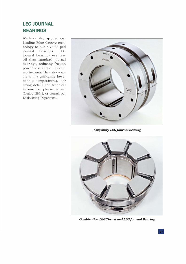
We have al so applied ou r
Leading Edge Groove tech-
nology to our pivoted padjournal bearings. LEG
journal bearings use less
oil than standard journal
bearings, reducing friction
power loss and oil system
requirements. They also oper-
ate with significantly lower
babbitt temperatures. For
sizing details and technical
information, please request
Catalog LEG-1, or consult ourEngineering Department.
LEG JOURNAL
BEARINGS
Kingsbury LEG Journal Bearing
Combination LEG Thrust and LEG Journal Bearing