Catalog Rulmenti
200
BALL & ROLLER BEARINGS POPULAR SIZE CAT.NO.203E-1 Ball & Roller Bearings Certificate No. 927265 ISO 9001/QS-9000
description
Catalog rulmenti
Transcript of Catalog Rulmenti
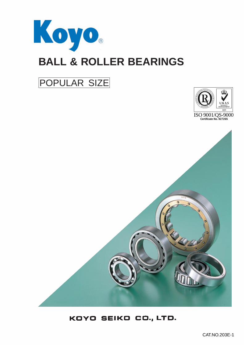
BALL & ROLLER BEARINGS
POPULAR SIZE
CAT.NO.203E-1
BALL & ROLLER BEARINGS
POPULAR SIZE
CAT.NO.203E-1Printed in Japan ’00.4-2CNK (’97.3)
Ball &
Roller B
earingsP
OP
ULA
R S
IZE
Certificate No. 927265ISO 9001/QS-9000

Copyright KOYO 1997
The contents of this catalogue are the copyright of KOYO and
may not be reproduced unless permission is granted.
Cares have been taken in every aspect to ensure the correctness
of the data contained in this catalogue but no liability can be
accepted for any mistakes or omissions.
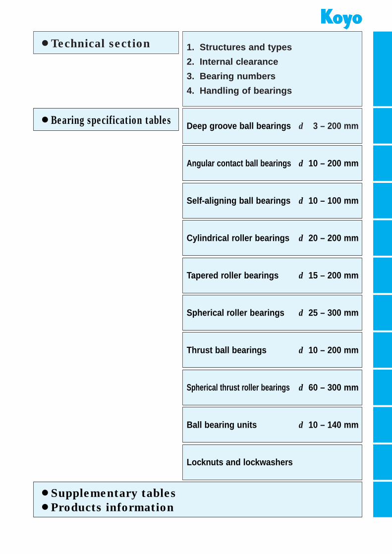
¡Technical section
¡Bearing specification tables
1. Structures and types
2. Internal clearance
3. Bearing numbers
4. Handling of bearings
Deep groove ball bearings d 3 – 200 mm
Angular contact ball bearings d 10 – 200 mm
Self-aligning ball bearings d 10 – 100 mm
Cylindrical roller bearings d 20 – 200 mm
Tapered roller bearings d 15 – 200 mm
Spherical roller bearings d 25 – 300 mm
Thrust ball bearings d 10 – 200 mm
Spherical thrust roller bearings d 60 – 300 mm
Ball bearing units d 10 – 140 mm
Locknuts and lockwashers
¡Supplementary tables
¡Products information
R
BALL & ROLLERBEARINGS
POPULAR SIZE
CAT. NO. 203E-1
¡VALUE & TECHNOLOGY
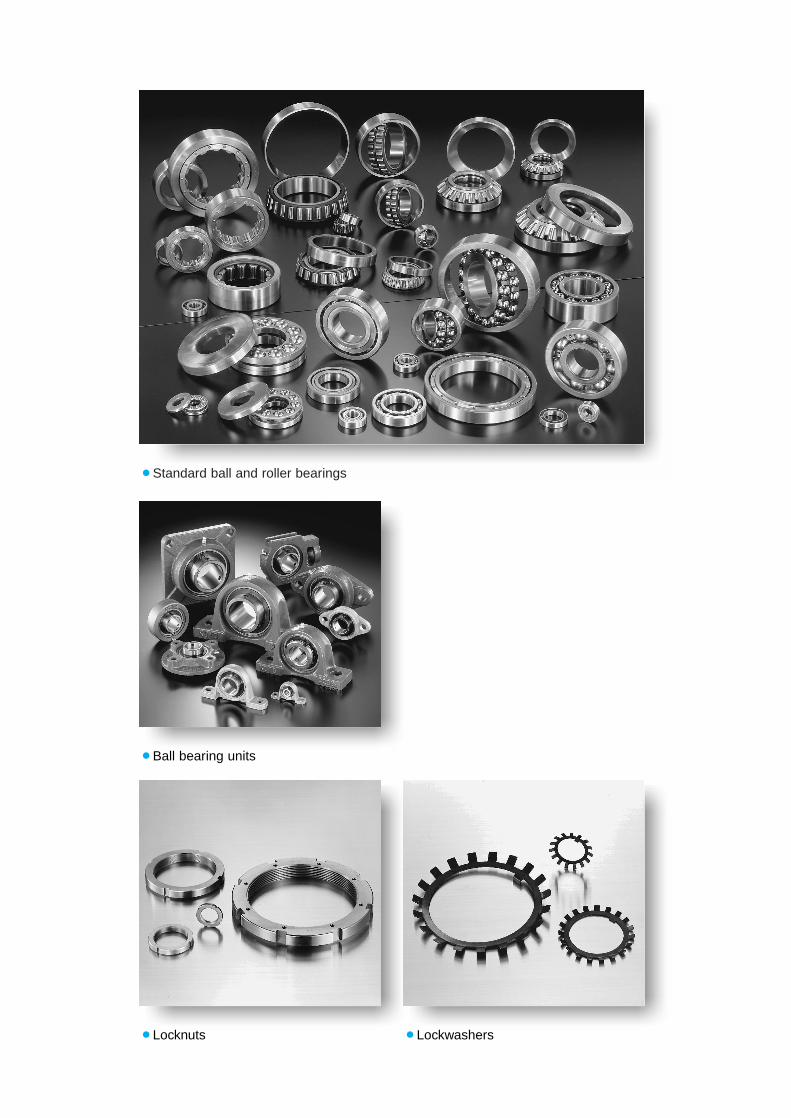
¡Standard ball and roller bearings
¡Ball bearing units
¡Locknuts ¡Lockwashers
Introduction
This catalogue is prepared to show most popular ball and rollerbearings used in various applications. These bearings are generallyavailable from stock.
As the technical information mentioned in this catalogue is limited,when more detailed information is required for new design of applica-tion, it is recommended that the KOYO General Catalogue is referred.
For trouble free operation of the application, it is recommended tokeep the bearings in proper condition avoiding from extreme high orlow temperature, wet, contamination, hitting, dropping, etc..Also proper handling and maintenance are required at mounting, regular inspection, overhaul, and dismounting by the use of suitabletools, jigs and lubricant.
*For improvements, as well as other reasons, the contents of thiscatalogue are subject to change without prior notice.
Reproduction is forbidden
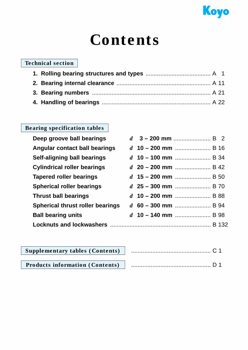
Contents
Technical section
1. Rolling bearing structures and types ........................................ A 1
2. Bearing internal clearance .......................................................... A 11
3. Bearing numbers ......................................................................... A 21
4. Handling of bearings ................................................................... A 22
Bearing specification tables
Supplementary tables (Contents)
Deep groove ball bearings d 3 – 200 mm ....................... B 2
Angular contact ball bearings d 10 – 200 mm ...................... B 16
Self-aligning ball bearings d 10 – 100 mm ...................... B 34
Cylindrical roller bearings d 20 – 200 mm ...................... B 42
Tapered roller bearings d 15 – 200 mm ...................... B 50
Spherical roller bearings d 25 – 300 mm ...................... B 70
Thrust ball bearings d 10 – 200 mm ...................... B 88
Spherical thrust roller bearings d 60 – 300 mm ...................... B 94
Ball bearing units d 10 – 140 mm ...................... B 98
Locknuts and lockwashers .............................................................. B 132
................................................. C 1
Products information (Contents) ................................................. D 1
A 1
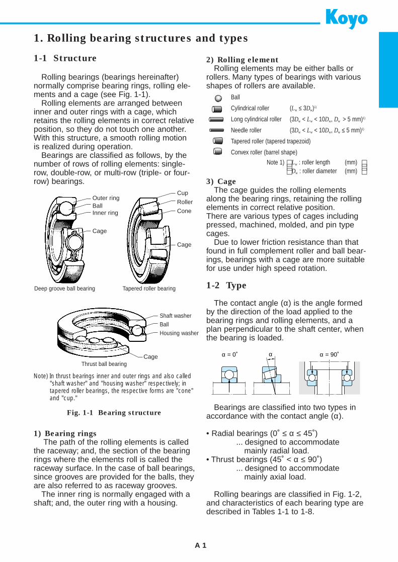
1-1 Structure
Rolling bearings (bearings hereinafter)normally comprise bearing rings, rolling ele-ments and a cage (see Fig. 1-1).
Rolling elements are arranged betweeninner and outer rings with a cage, whichretains the rolling elements in correct relativeposition, so they do not touch one another.With this structure, a smooth rolling motionis realized during operation.
Bearings are classified as follows, by thenumber of rows of rolling elements: single-row, double-row, or multi-row (triple- or four-row) bearings.
1) Bearing rings
The path of the rolling elements is calledthe raceway; and, the section of the bearingrings where the elements roll is called theraceway surface. In the case of ball bearings,since grooves are provided for the balls, theyare also referred to as raceway grooves.
The inner ring is normally engaged with ashaft; and, the outer ring with a housing.
Fig. 1-1 Bearing structure
1. Rolling bearing structures and types
2) Rolling element
Rolling elements may be either balls orrollers. Many types of bearings with variousshapes of rollers are available.
3) Cage
The cage guides the rolling elementsalong the bearing rings, retaining the rollingelements in correct relative position.There are various types of cages includingpressed, machined, molded, and pin typecages.
Due to lower friction resistance than thatfound in full complement roller and ball bear-ings, bearings with a cage are more suitablefor use under high speed rotation.
1-2 Type
The contact angle (α) is the angle formedby the direction of the load applied to thebearing rings and rolling elements, and aplan perpendicular to the shaft center, whenthe bearing is loaded.
Bearings are classified into two types inaccordance with the contact angle (α).
• Radial bearings (0˚ ≤ α ≤ 45˚)... designed to accommodate
mainly radial load.• Thrust bearings (45˚ < α ≤ 90˚)
... designed to accommodatemainly axial load.
Rolling bearings are classified in Fig. 1-2,and characteristics of each bearing type aredescribed in Tables 1-1 to 1-8.
Ball
Cylindrical roller (Lw ≤ 3Dw)1)
Long cylindrical roller (3Dw < Lw < 10Dw, Dw > 5 mm)1)
Needle roller (3Dw < Lw < 10Dw, Dw ≤ 5 mm)1)
Tapered roller (tapered trapezoid)
Convex roller (barrel shape)
Lw : roller length (mm)Dw : roller diameter (mm)
Note 1)
Note) In thrust bearings inner and outer rings and also called"shaft washer" and "housing washer" respectively; intapered roller bearings, the respective forms are "cone"and "cup."
Deep groove ball bearing Tapered roller bearing
Thrust ball bearing
Outer ringBallInner ring
Cage
Cup
Roller
Cone
Cage
Shaft washerBallHousing washer
Cage α = 90˚α = 0˚ α
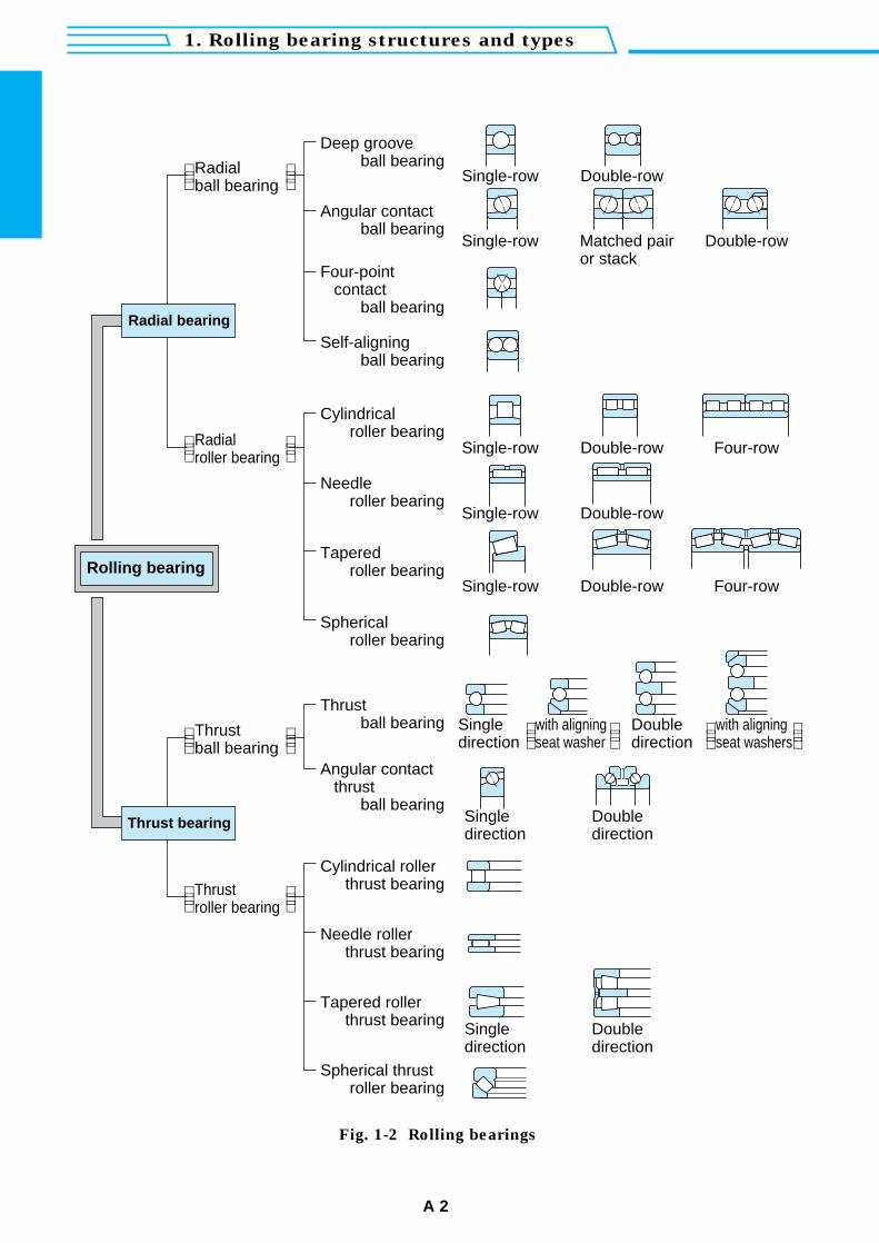
1. Rolling bearing structures and types
A 2
Radialball bearing
Single-row
Single-row
Double-row
Matched pairor stack
Double-row
Radialroller bearing
Single-row Double-row Four-row
Single-row Double-row
Single-row Double-row Four-row
Thrustball bearing
Singledirection
with aligningseat washer
Doubledirection
Singledirection
Doubledirection
Singledirection
Doubledirection
with aligningseat washers
Thrustroller bearing
Deep groove ball bearing
Angular contact ball bearing
Four-point contact
ball bearing
Angular contact thrust
ball bearing
Self-aligning ball bearing
Cylindricalroller bearing
Needleroller bearing
Taperedroller bearing
Sphericalroller bearing
Cylindrical roller thrust bearing
Needle roller thrust bearing
Tapered roller thrust bearing
Spherical thrust roller bearing
Thrustball bearing
Radial bearing
Thrust bearing
Rolling bearing
Fig. 1-2 Rolling bearings
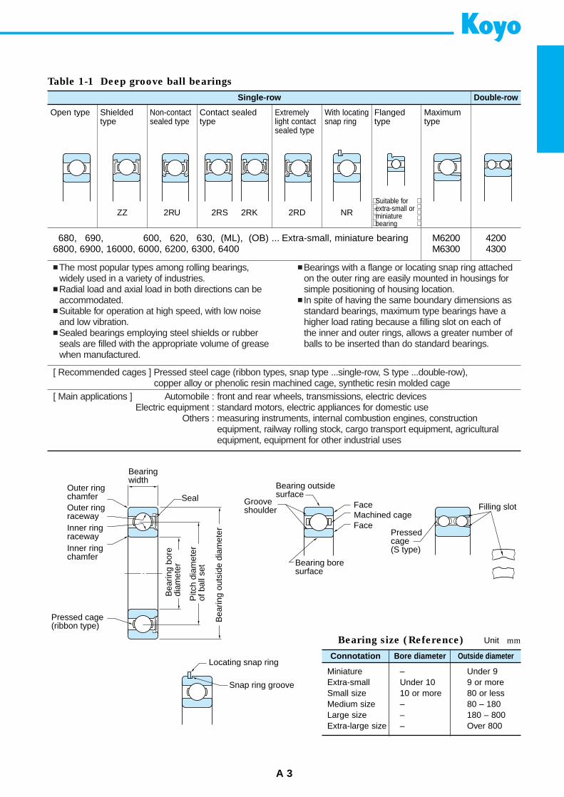
The most popular types among rolling bearings,widely used in a variety of industries.
Radial load and axial load in both directions can beaccommodated.
Suitable for operation at high speed, with low noiseand low vibration.
Sealed bearings employing steel shields or rubberseals are filled with the appropriate volume of greasewhen manufactured.
Bearings with a flange or locating snap ring attachedon the outer ring are easily mounted in housings forsimple positioning of housing location.
In spite of having the same boundary dimensions asstandard bearings, maximum type bearings have ahigher load rating because a filling slot on each ofthe inner and outer rings, allows a greater number ofballs to be inserted than do standard bearings.
[ Recommended cages ] Pressed steel cage (ribbon types, snap type ...single-row, S type ...double-row), copper alloy or phenolic resin machined cage, synthetic resin molded cage
[ Main applications ] Automobile : front and rear wheels, transmissions, electric devicesElectric equipment : standard motors, electric appliances for domestic use
Others : measuring instruments, internal combustion engines, construction equipment, railway rolling stock, cargo transport equipment, agriculturalequipment, equipment for other industrial uses
A 3
Table 1-1 Deep groove ball bearings
Single-row Double-row
Open type Shieldedtype
ZZ
Non-contactsealed type
Contact sealedtype
Extremelylight contactsealed type
With locatingsnap ring
Flangedtype
Maximumtype
2RU 2RS 2RK 2RD NRSuitable forextra-small orminiaturebearing
680, 690, 600, 620, 630, (ML), (OB) ... Extra-small, miniature bearing6800, 6900, 16000, 6000, 6200, 6300, 6400
M6200M6300
42004300
Bearing size (Reference) Unit mm
Connotation
Miniature – Under 9Extra-small Under 10 9 or moreSmall size 10 or more 80 or lessMedium size – 80 – 180Large size – 180 – 800Extra-large size – Over 800
Bore diameter Outside diameter
Bearingwidth
Outer ringchamferOuter ringracewayInner ringracewayInner ring chamfer
Seal
Pressed cage (ribbon type)
Bea
ring
bore
diam
eter
Pitc
h di
amet
erof
bal
l set
Bea
ring
outs
ide
diam
eter
Grooveshoulder
Bearing outside surface
Machined cageFace
Face
Bearing boresurface
Filling slot
Pressed cage (S type)
Locating snap ring
Snap ring groove
1. Rolling bearing structures and types
A 4
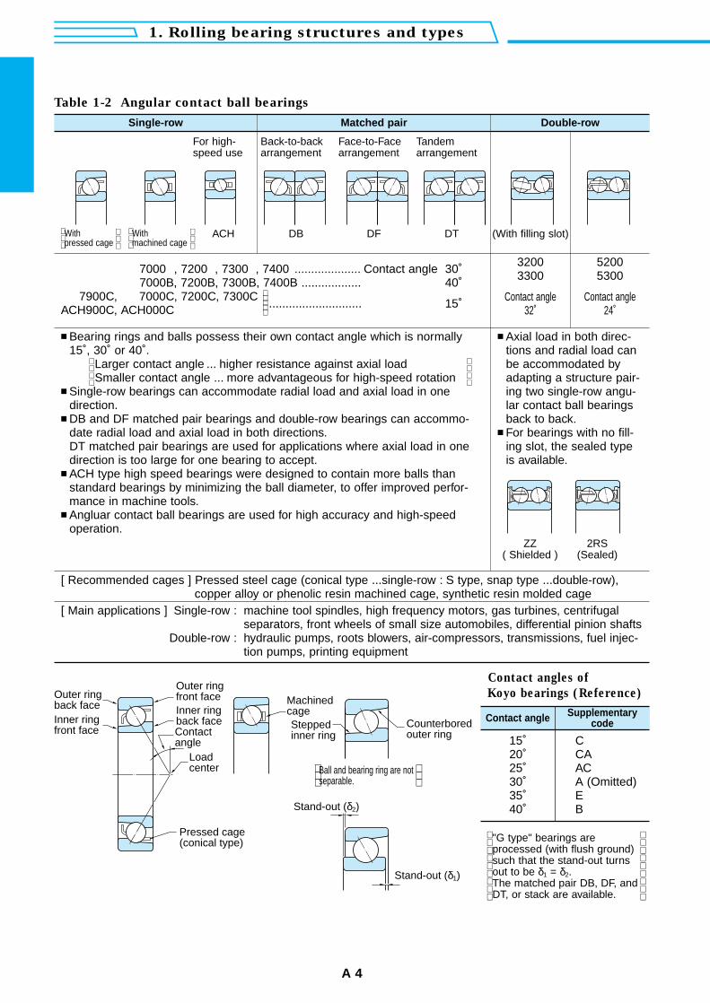
Bearing rings and balls possess their own contact angle which is normally15˚, 30˚ or 40˚.
Larger contact angle ... higher resistance against axial loadSmaller contact angle ... more advantageous for high-speed rotation
Single-row bearings can accommodate radial load and axial load in one direction.
DB and DF matched pair bearings and double-row bearings can accommo-date radial load and axial load in both directions.DT matched pair bearings are used for applications where axial load in onedirection is too large for one bearing to accept.
ACH type high speed bearings were designed to contain more balls thanstandard bearings by minimizing the ball diameter, to offer improved perfor-mance in machine tools.
Angluar contact ball bearings are used for high accuracy and high-speedoperation.
Axial load in both direc-tions and radial load canbe accommodated byadapting a structure pair-ing two single-row angu-lar contact ball bearingsback to back.
For bearings with no fill-ing slot, the sealed typeis available.
[ Recommended cages ] Pressed steel cage (conical type ...single-row : S type, snap type ...double-row),copper alloy or phenolic resin machined cage, synthetic resin molded cage
[ Main applications ] Single-row : machine tool spindles, high frequency motors, gas turbines, centrifugalseparators, front wheels of small size automobiles, differential pinion shafts
Double-row : hydraulic pumps, roots blowers, air-compressors, transmissions, fuel injec-tion pumps, printing equipment
Table 1-2 Angular contact ball bearings
Single-row Matched pair Double-row
For high-speed use
Back-to-backarrangement
Face-to-Facearrangement
Tandemarrangement
ACH DB DF DT (With filling slot)
ZZ( Shielded )
2RS(Sealed)
Withpressed cage
Withmachined cage
7000 , 7200 , 7300 , 7400 .................... Contact angle 30˚7000B, 7200B, 7300B, 7400B .................. 40˚
7900C, 7000C, 7200C, 7300C............................ 15˚ACH900C, ACH000C
32003300
Contact angle32˚
52005300
Contact angle24˚
Contact angles of
Koyo bearings (Reference)
Contact angle
15˚ C20˚ CA25˚ AC30˚ A (Omitted)35˚ E40˚ B
Supplementarycode
"G type" bearings areprocessed (with flush ground)such that the stand-out turnsout to be δ1 = δ2.The matched pair DB, DF, andDT, or stack are available.
Stand-out (δ2)
Outer ring back faceInner ring front face
Outer ring front faceInner ring back faceContact angle
Load center
Pressed cage (conical type)
Machined cageSteppedinner ring
Counterbored outer ring
Stand-out (δ1)
Ball and bearing ring are not separable.
A 5
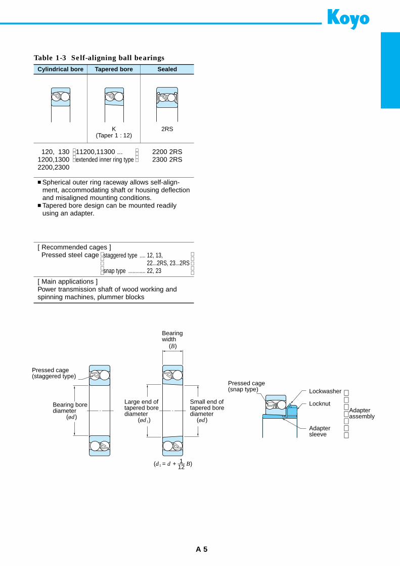
Spherical outer ring raceway allows self-align-ment, accommodating shaft or housing deflectionand misaligned mounting conditions.
Tapered bore design can be mounted readilyusing an adapter.
[ Recommended cages ]Pressed steel cage
[ Main applications ]Power transmission shaft of wood working andspinning machines, plummer blocks
Table 1-3 Self-aligning ball bearings
Cylindrical bore Tapered bore
K(Taper 1 : 12)
Sealed
2RS
120, 130 11200,11300 ...1200,1300 extended inner ring type2200,2300
2200 2RS2300 2RS
staggered type .... 12, 13,22...2RS, 23...2RS
snap type ............ 22, 23
Adapterassembly
Pressed cage (staggered type)
Bearing bore diameter (ød)
Bearing width
(B)
Large end of tapered bore diameter (ød1)
Small end of tapered bore diameter (ød)
(d1 = d + B)112
Pressed cage (snap type) Lockwasher
Locknut
Adapter sleeve
1. Rolling bearing structures and types
A 6
Table 1-4 Cylindrical roller bearings
Single-row
NU
Double-row
NNU NN
Four-row
Mainly use onrolling mill roll neck
NJ NUP N NF NH
NU1000, NU200(R) , NU300(R), NU400NU2200(R), NU2300(R)NU3200 , NU3300
Cylindrical bore Tapered boreNNU4900 NNU4900KNN3000 NN3000K
(FC), (4CR)
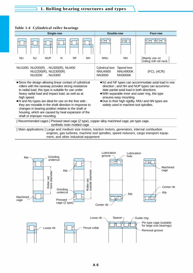
Since the design allowing linear contact of cylindricalrollers with the raceway provides strong resistance to radial load, this type is suitable for use under heavy radial load and impact load, as well as at high speed.
N and NU types are ideal for use on the free side :they are movable in the shaft direction in response tochanges in bearing position relative to the shaft orhousing, which are caused by heat expansion of theshaft or improper mounting.
NJ and NF types can accommodate axial load in onedirection ; and NH and NUP types can accommo-date partial axial load in both directions.
With separable inner and outer ring, this typeensures easy mounting.
Due to their high rigidity, NNU and NN types arewidely used in machine tool spindles.
[ Recommended cages ] Pressed steel cage (Z type), copper alloy machined cage, pin type cage,synthetic resin molded cage
[ Main applications ] Large and medium size motors, traction motors, generators, internal combustionengines, gas turbines, machine tool spindles, speed reducers, cargo transport equip-ment, and other industrial equipment
Rib
Rib
Rib
Grinding undercut
Machined cage
Rol
ler
set
bore
dia
met
er
Rol
ler
set
outs
ide
diam
eter
Grinding undercut
Pressed cage (Z type)
Lubrication groove
Lubrication hole
Center rib
Machined cage
Center rib
Rib
Loose rib Thrust collar
Loose rib Spacer Guide ring
Pin type cage (suitable for large size bearings)
Removal groove
[ Main applications ] Automobile : front and rear wheels, transmissions, differential pinionOthers : machine tool spindles, construction equipment, large size agricultural
equipment, railway rolling stock speed reduction gears, rolling mill rollnecks and speed reducers, etc
A 7
Table 1-5 Tapered roller bearings
Single-row
Flanged type
Double-row
TDO type TDI type
Four-row
Mainly used onrolling mill roll neck
32900JR32000JR33000JR33100JR
30200JR 32200JR33200JR30300JR32300JR
30200CR32200CR30300CR32300CR
30300DJ30300DJR31300JR
4620046200A4630046300A(46T)
4520045300(45T)
372004720047300(47T)
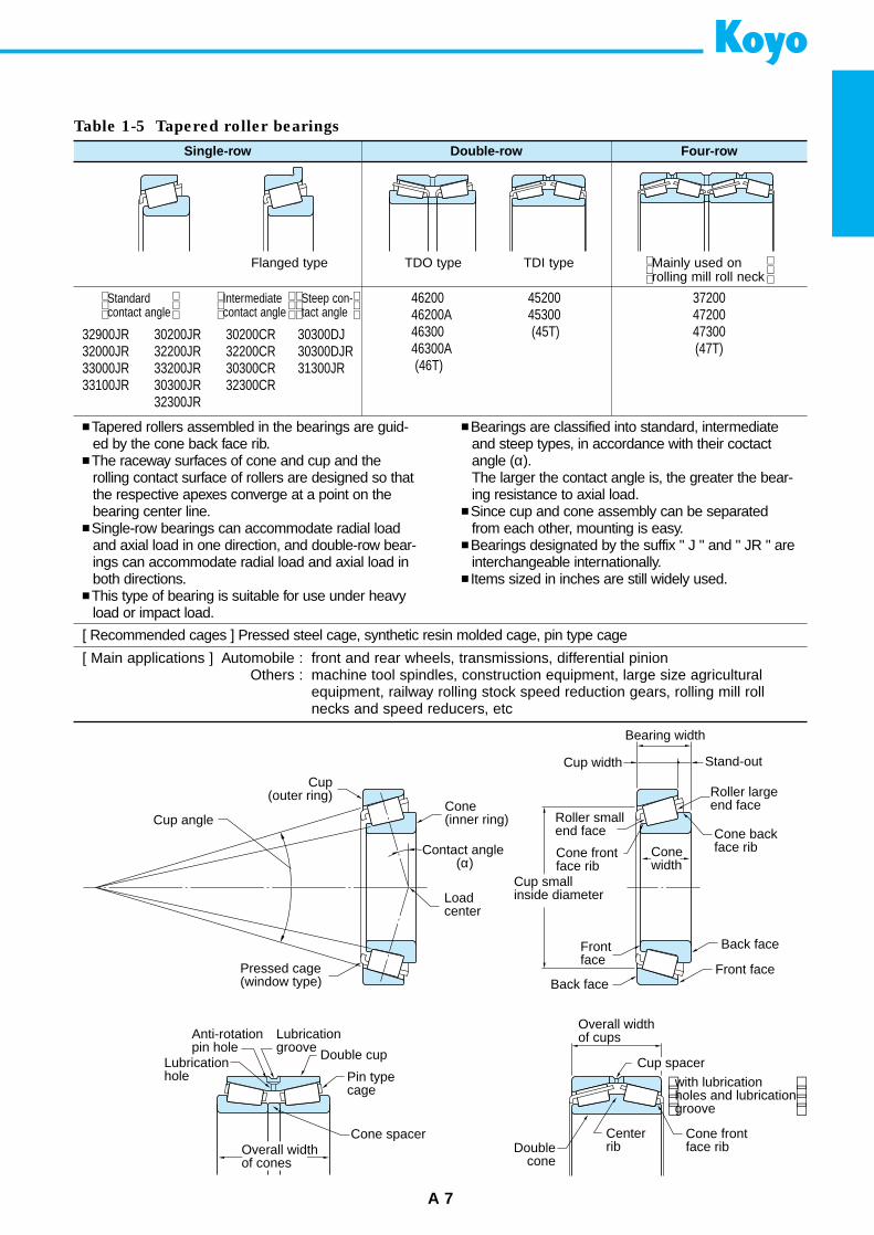
Tapered rollers assembled in the bearings are guid-ed by the cone back face rib.
The raceway surfaces of cone and cup and therolling contact surface of rollers are designed so thatthe respective apexes converge at a point on thebearing center line.
Single-row bearings can accommodate radial loadand axial load in one direction, and double-row bear-ings can accommodate radial load and axial load inboth directions.
This type of bearing is suitable for use under heavyload or impact load.
Bearings are classified into standard, intermediateand steep types, in accordance with their coctactangle (α).The larger the contact angle is, the greater the bear-ing resistance to axial load.
Since cup and cone assembly can be separatedfrom each other, mounting is easy.
Bearings designated by the suffix " J " and " JR " areinterchangeable internationally.
Items sized in inches are still widely used.
[ Recommended cages ] Pressed steel cage, synthetic resin molded cage, pin type cage
Standardcontact angle
Intermediatecontact angle
Steep con-tact angle
Cone frontface rib
Cup(outer ring)
Cone (inner ring)
Load center
Contact angle (α)
Pressed cage (window type)
Cup angle
Bearing width
Cup width
Roller small end face
Cup small inside diameter
Front face
Back face
Back face
Stand-out
Roller large end face
Cone backface rib
Front face
Cone width
Anti-rotation pin hole
Lubrication hole
Lubrication groove Double cup
Pin typecage
Overall width of cones
Overall width of cups
Cone front face rib
Doublecone
Centerrib
with lubrication holes and lubrication groove
Cup spacer
Cone spacer
1. Rolling bearing structures and types
A 8
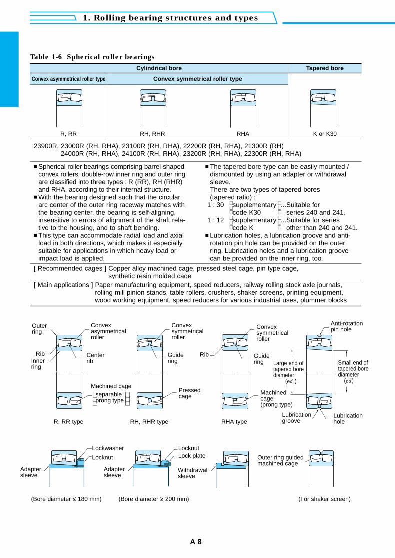
Spherical roller bearings comprising barrel-shapedconvex rollers, double-row inner ring and outer ringare classified into three types : R (RR), RH (RHR)and RHA, according to their internal structure.
With the bearing designed such that the circulararc center of the outer ring raceway matches withthe bearing center, the bearing is self-aligning,insensitive to errors of alignment of the shaft rela-tive to the housing, and to shaft bending.
This type can accommodate radial load and axialload in both directions, which makes it especiallysuitable for applications in which heavy load orimpact load is applied.
The tapered bore type can be easily mounted /dismounted by using an adapter or withdrawalsleeve.There are two types of tapered bores(tapered ratio) :
1 : 30 supplementary ...Suitable forcode K30 series 240 and 241.
1 : 12 supplementary ...Suitable for seriescode K other than 240 and 241.
Lubrication holes, a lubrication groove and anti-rotation pin hole can be provided on the outerring. Lubrication holes and a lubrication groovecan be provided on the inner ring, too.
[ Recommended cages ] Copper alloy machined cage, pressed steel cage, pin type cage,synthetic resin molded cage
[ Main applications ] Paper manufacturing equipment, speed reducers, railway rolling stock axle journals,rolling mill pinion stands, table rollers, crushers, shaker screens, printing equipment,wood working equipment, speed reducers for various industrial uses, plummer blocks
Table 1-6 Spherical roller bearings
Cylindrical bore Tapered bore
Convex asymmetrical roller type Convex symmetrical roller type
R, RR RH, RHR RHA K or K30
23900R, 23000R (RH, RHA), 23100R (RH, RHA), 22200R (RH, RHA), 21300R (RH)24000R (RH, RHA), 24100R (RH, RHA), 23200R (RH, RHA), 22300R (RH, RHA)
Convex asymmetrical roller
Rib RibCenter rib
Machined cageseparable prong type
Outer ring
Convex symmetrical roller
Inner ring
Guide ring
Guide ring
Pressed cage
Convex symmetrical roller
Machined cage (prong type)
Anti-rotation pin hole
Large end of tapered bore diameter (ød1)
Small end of tapered bore diameter (ød)
Lubrication hole
Lubrication groove
Adapter sleeve
Adapter sleeve
Lockwasher
Locknut
LocknutLock plate
Withdrawal sleeve
Outer ring guided machined cage
R, RR type RH, RHR type RHA type
(Bore diameter ≤ 180 mm) (Bore diameter ≥ 200 mm) (For shaker screen)
A 9
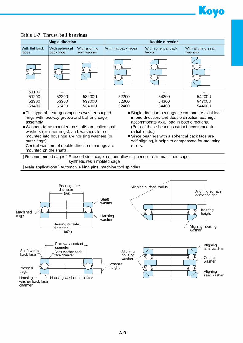
This type of bearing comprises washer-shapedrings with raceway groove and ball and cageassembly.
Washers to be mounted on shafts are called shaftwashers (or inner rings); and, washers to bemounted into housings are housing washers (orouter rings).Central washers of double direction bearings aremounted on the shafts.
Single direction bearings accommodate axial loadin one direction, and double direction bearingsaccommodate axial load in both directions.(Both of these bearings cannot accommodateradial loads.)
Since bearings with a spherical back face areself-aligning, it helps to compensate for mountingerrors.
[ Recommended cages ] Pressed steel cage, copper alloy or phenolic resin machined cage,synthetic resin molded cage
[ Main applications ] Automobile king pins, machine tool spindles
Table 1-7 Thrust ball bearings
Single direction Double direction
With flat backfaces
With flat back faces With spherical backfaces
With aligning seatwashers
51100512005130051400
With sphericalback face
–532005330053400
With aligningseat washer
–53200U53300U53400U
–522005230052400
–542005430054400
–54200U54300U54400U
Machined cage
Bearing bore diameter (ød)
Bearing outsidediameter (øD )
Shaft washer
Housing washer
Aligning surface radius
Pressedcage
Aligning surface center height
Aligning housing washer
Bearing height
Shaft washer back face
Raceway contact diameterShaft washer backface chamfer
Housing washer back face chamfer
Housing washer back face
Washer height
Aligning housing washer
Aligning seat washer
Central washer
Aligning seat washer
1. Rolling bearing structures and types
A 10
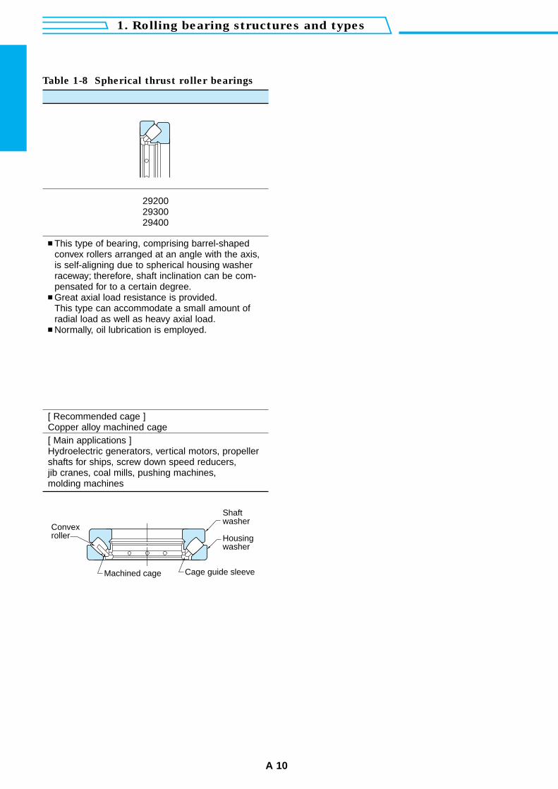
This type of bearing, comprising barrel-shapedconvex rollers arranged at an angle with the axis,is self-aligning due to spherical housing washerraceway; therefore, shaft inclination can be com-pensated for to a certain degree.
Great axial load resistance is provided.This type can accommodate a small amount ofradial load as well as heavy axial load.
Normally, oil lubrication is employed.
[ Recommended cage ]Copper alloy machined cage[ Main applications ]Hydroelectric generators, vertical motors, propellershafts for ships, screw down speed reducers, jib cranes, coal mills, pushing machines, molding machines
Table 1-8 Spherical thrust roller bearings
292002930029400
Cage guide sleeve
Convex roller
Machined cage
Shaft washer
Housing washer
A 11
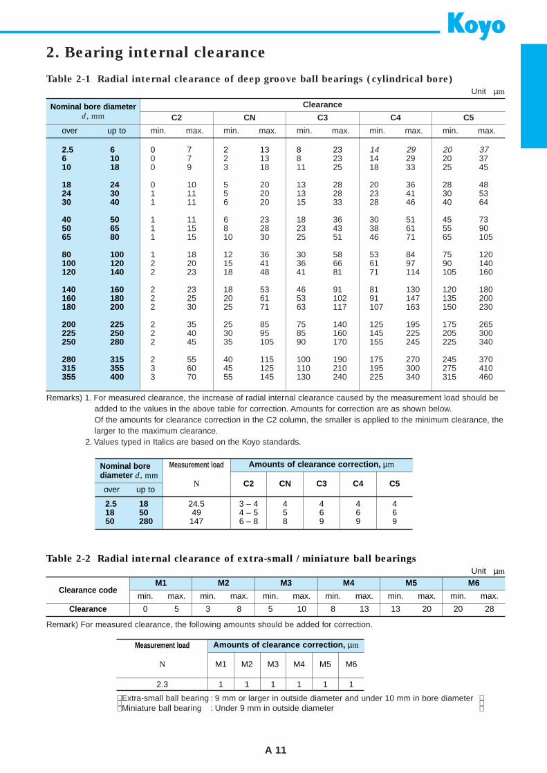
2. Bearing internal clearance
Table 2-1 Radial internal clearance of deep groove ball bearings (cylindrical bore)
Unit µm
Clearance
C2
min. max. min. max. min. max. min. max. min. max.
CN C3 C4 C5Nominal bore diameter
d, mm
over up to
2.5 66 1010 18
18 2424 3030 40
40 5050 6565 80
80 100100 120120 140
140 160160 180180 200
200 225225 250250 280
280 315315 355355 400
0 7 2 13 8 23 14 29 20 370 7 2 13 8 23 14 29 20 370 9 3 18 11 25 18 33 25 45
0 10 5 20 13 28 20 36 28 481 11 5 20 13 28 23 41 30 531 11 6 20 15 33 28 46 40 64
1 11 6 23 18 36 30 51 45 731 15 8 28 23 43 38 61 55 901 15 10 30 25 51 46 71 65 105
1 18 12 36 30 58 53 84 75 1202 20 15 41 36 66 61 97 90 1402 23 18 48 41 81 71 114 105 160
2 23 18 53 46 91 81 130 120 1802 25 20 61 53 102 91 147 135 2002 30 25 71 63 117 107 163 150 230
2 35 25 85 75 140 125 195 175 2652 40 30 95 85 160 145 225 205 3002 45 35 105 90 170 155 245 225 340
2 55 40 115 100 190 175 270 245 3703 60 45 125 110 210 195 300 275 4103 70 55 145 130 240 225 340 315 460
Remarks) 1. For measured clearance, the increase of radial internal clearance caused by the measurement load should beadded to the values in the above table for correction. Amounts for correction are as shown below.Of the amounts for clearance correction in the C2 column, the smaller is applied to the minimum clearance, thelarger to the maximum clearance.
2. Values typed in Italics are based on the Koyo standards.
Remark) For measured clearance, the following amounts should be added for correction.
Extra-small ball bearing : 9 mm or larger in outside diameter and under 10 mm in bore diameterMiniature ball bearing : Under 9 mm in outside diameter
Measurement load Amounts of clearance correction, µm
C2 CN C3 C4 C5N
Nominal borediameter d, mm
over up to
2.5 1818 5050 280
24.549147
3 – 4 4 4 4 44 – 5 5 6 6 66 – 8 8 9 9 9
Measurement load Amounts of clearance correction, µm
M1 M2 M3 M4 M5 M6N
2.3 1 1 1 1 1 1
Table 2-2 Radial internal clearance of extra-small / miniature ball bearings
Unit µm
M1 M2 M3 M4 M5 M6Clearance code
Clearance
min.
0 5 3 8 5 10 8 13 13 20 20 28
max. min. max. min. max. min. max. min. max. min. max.
C3 C4
2. Bearing internal clearance
A 12
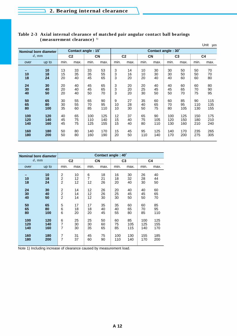
Table 2-3 Axial internal clearance of matched pair angular contact ball bearings
(measurement clearance) 1)
Unit µm
Contact angle : 15˚ Contact angle : 30˚
C2
min. max.
Nominal bore diameterd, mm
over up to
– 1010 1818 24
24 3030 4040 50
50 6565 8080 100
100 120120 140140 160
160 180180 200
13 33 33 53 3 14 10 30 30 50 50 7015 35 35 55 3 16 10 30 30 50 50 7020 40 45 65 3 20 20 40 40 60 60 80
20 40 45 65 3 20 20 40 40 60 60 8020 40 45 65 3 20 25 45 45 65 70 9020 40 50 70 3 20 30 50 50 70 75 95
30 55 65 90 9 27 35 60 60 85 90 11530 55 70 95 10 28 40 65 70 95 110 13535 60 85 110 10 30 50 75 80 105 130 155
40 65 100 125 12 37 65 90 100 125 150 17545 75 110 140 15 40 75 105 120 150 180 21045 75 125 155 15 40 80 110 130 160 210 240
50 80 140 170 15 45 95 125 140 170 235 26550 80 160 190 20 50 110 140 170 200 275 305
Note 1) Including increase of clearance caused by measurement load.
CN
min. max. min. max.
CN
min. max. min. max. min. max.
Contact angle : 40˚
C2
min. max.
Nominal bore diameterd, mm
over up to
– 1010 1818 24
24 3030 4040 50
50 6565 8080 100
100 120120 140140 160
160 180180 200
2 10 6 18 16 30 26 402 12 7 21 18 32 28 442 12 12 26 20 40 30 50
2 14 12 26 20 40 40 602 14 12 26 25 45 45 652 14 12 30 30 50 50 70
5 17 17 35 35 60 60 856 18 18 40 40 65 70 956 20 20 45 55 80 85 110
6 25 25 50 60 85 100 1257 30 30 60 75 105 125 1557 30 35 65 85 115 140 170
7 31 45 75 100 130 155 1857 37 60 90 110 140 170 200
CN
min. max.
C3
min. max.
C4
min. max.
C2
A 13
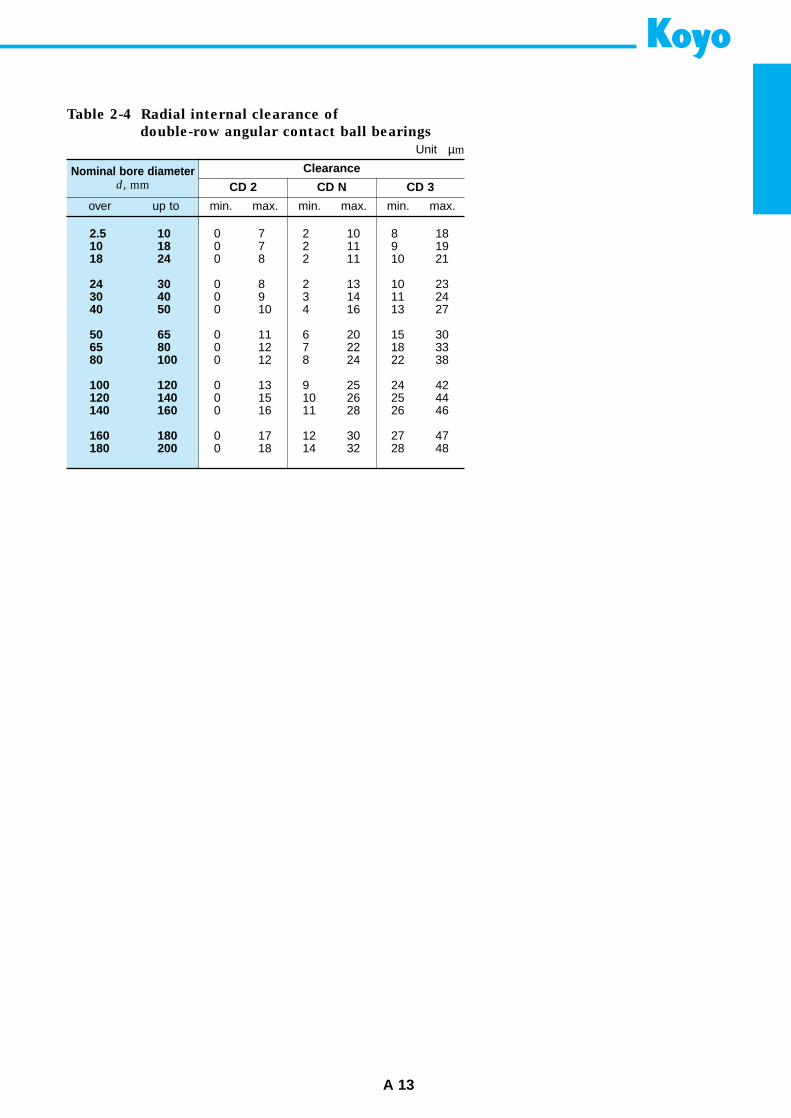
Table 2-4 Radial internal clearance of
double-row angular contact ball bearings
Unit µm
Clearance
CD 2
min. max.
Nominal bore diameterd, mm
over up to
2.5 1010 1818 24
24 3030 4040 50
50 6565 8080 100
100 120120 140140 160
160 180180 200
0 7 2 10 8 180 7 2 11 9 190 8 2 11 10 21
0 8 2 13 10 230 9 3 14 11 240 10 4 16 13 27
0 11 6 20 15 300 12 7 22 18 330 12 8 24 22 38
0 13 9 25 24 420 15 10 26 25 440 16 11 28 26 46
0 17 12 30 27 470 18 14 32 28 48
CD N
min. max.
CD 3
min. max.
2. Bearing internal clearance
A 14
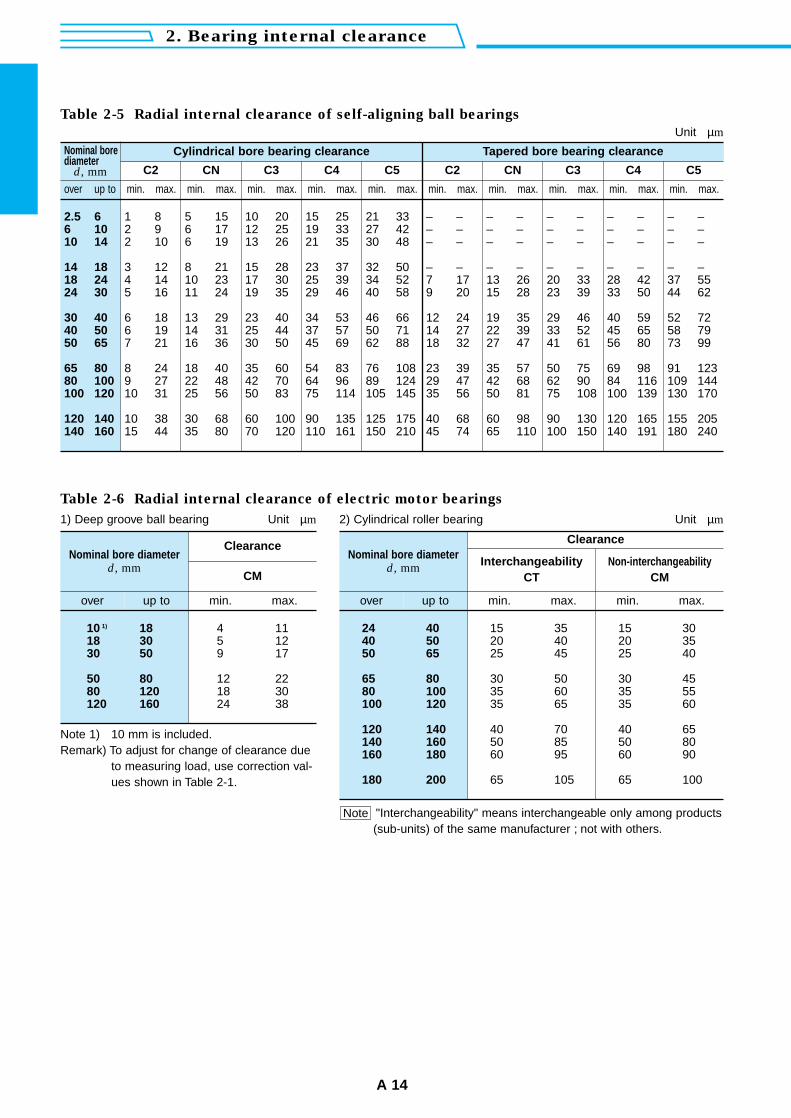
Table 2-5 Radial internal clearance of self-aligning ball bearings
Unit µm
Cylindrical bore bearing clearance Tapered bore bearing clearance
C2
min. max.
Nominal borediameter
d, mm
over up to
2.5 66 1010 14
14 1818 2424 30
30 4040 5050 65
65 8080 100100 120
120 140140 160
1 8 5 15 10 20 15 25 21 33 – – – – – – – – – –2 9 6 17 12 25 19 33 27 42 – – – – – – – – – –2 10 6 19 13 26 21 35 30 48 – – – – – – – – – –
3 12 8 21 15 28 23 37 32 50 – – – – – – – – – –4 14 10 23 17 30 25 39 34 52 7 17 13 26 20 33 28 42 37 555 16 11 24 19 35 29 46 40 58 9 20 15 28 23 39 33 50 44 62
6 18 13 29 23 40 34 53 46 66 12 24 19 35 29 46 40 59 52 726 19 14 31 25 44 37 57 50 71 14 27 22 39 33 52 45 65 58 797 21 16 36 30 50 45 69 62 88 18 32 27 47 41 61 56 80 73 99
8 24 18 40 35 60 54 83 76 108 23 39 35 57 50 75 69 98 91 1239 27 22 48 42 70 64 96 89 124 29 47 42 68 62 90 84 116 109 14410 31 25 56 50 83 75 114 105 145 35 56 50 81 75 108 100 139 130 170
10 38 30 68 60 100 90 135 125 175 40 68 60 98 90 130 120 165 155 20515 44 35 80 70 120 110 161 150 210 45 74 65 110 100 150 140 191 180 240
CN
min. max.
C3
min. max.
C4
min. max.
C5
min. max.
C2
min. max.
CN
min. max.
C3
min. max.
C4
min. max.
C5
min. max.
Table 2-6 Radial internal clearance of electric motor bearings
1) Deep groove ball bearing Unit µm 2) Cylindrical roller bearing Unit µm
Clearance
CM
Nominal bore diameterd, mm
over up to
10 1) 1818 3030 50
50 8080 120120 160
4 115 129 17
12 2218 3024 38
min. max.
Note 1) 10 mm is included.Remark) To adjust for change of clearance due
to measuring load, use correction val-ues shown in Table 2-1.
Clearance
InterchangeabilityCT
Nominal bore diameterd, mm
over up to
24 4040 5050 65
65 8080 100100 120
120 140140 160160 180
180 200
15 35 15 3020 40 20 3525 45 25 40
30 50 30 4535 60 35 5535 65 35 60
40 70 40 6550 85 50 8060 95 60 90
65 105 65 100
min. max.
Non-interchangeabilityCM
min. max.
"Interchangeability" means interchangeable only among products(sub-units) of the same manufacturer ; not with others.
Note

A 15
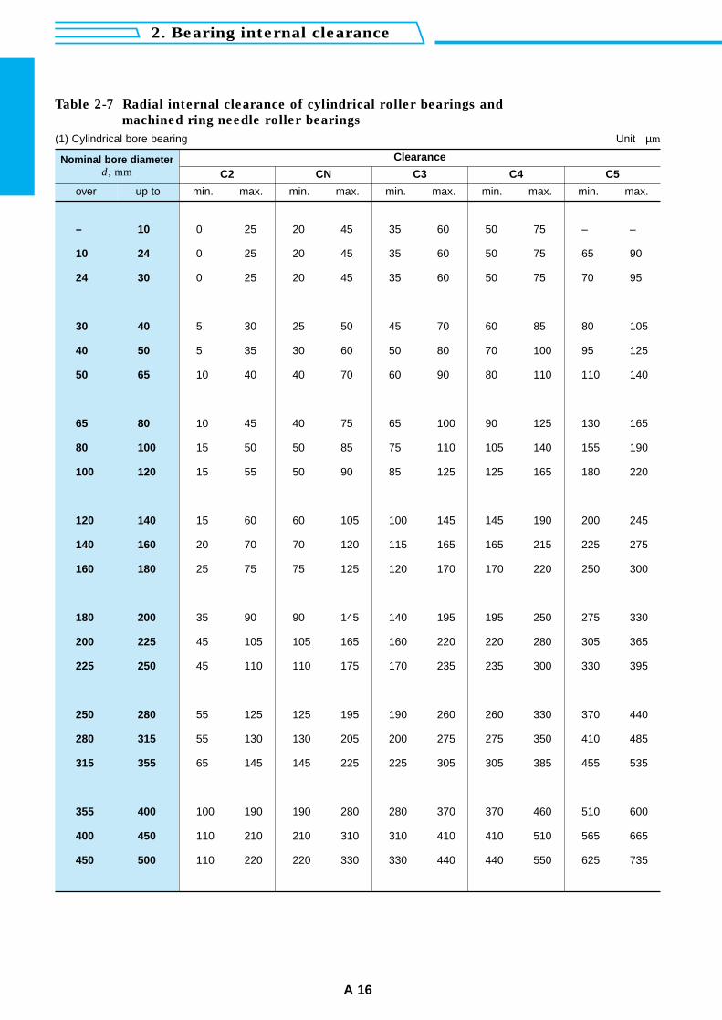
– 10
10 24
24 30
30 40
40 50
50 65
65 80
80 100
100 120
120 140
140 160
160 180
180 200
200 225
225 250
250 280
280 315
315 355
355 400
400 450
450 500
Table 2-7 Radial internal clearance of cylindrical roller bearings and
machined ring needle roller bearings
(1) Cylindrical bore bearing Unit µm
2. Bearing internal clearance
A 16
Clearance
C2
min. max. min. max. min. max. min. max. min. max.
CN C3 C4 C5Nominal bore diameter
d, mm
over up to
0 25 20 45 35 60 50 75 – –
0 25 20 45 35 60 50 75 65 90
0 25 20 45 35 60 50 75 70 95
5 30 25 50 45 70 60 85 80 105
5 35 30 60 50 80 70 100 95 125
10 40 40 70 60 90 80 110 110 140
10 45 40 75 65 100 90 125 130 165
15 50 50 85 75 110 105 140 155 190
15 55 50 90 85 125 125 165 180 220
15 60 60 105 100 145 145 190 200 245
20 70 70 120 115 165 165 215 225 275
25 75 75 125 120 170 170 220 250 300
35 90 90 145 140 195 195 250 275 330
45 105 105 165 160 220 220 280 305 365
45 110 110 175 170 235 235 300 330 395
55 125 125 195 190 260 260 330 370 440
55 130 130 205 200 275 275 350 410 485
65 145 145 225 225 305 305 385 455 535
100 190 190 280 280 370 370 460 510 600
110 210 210 310 310 410 410 510 565 665
110 220 220 330 330 440 440 550 625 735
12 14
14 24
24 30
30 40
40 50
50 65
65 80
80 100
100 120
120 140
140 160
160 180
180 200
200 225
225 250
250 280
280 315
315 355
355 400
400 450
450 500
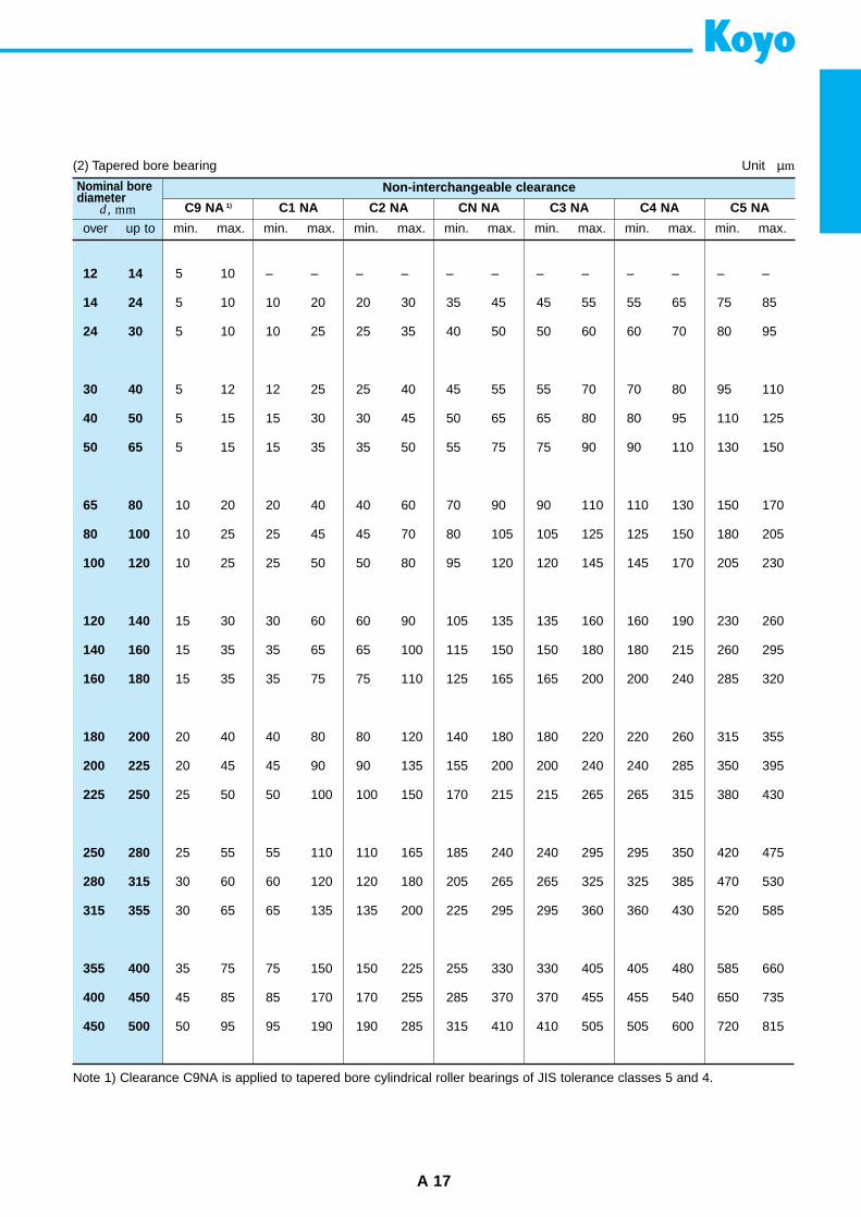
A 17
(2) Tapered bore bearing Unit µm
Non-interchangeable clearance
C9 NA 1)
min. max.
C1 NA
min. max.
C2 NA
min. max.
CN NA
min. max.
C3 NA
min. max.
C4 NA
min. max.
C5 NA
min. max.
Nominal borediameter
d, mm
over up to
5 10 – – – – – – – – – – – –
5 10 10 20 20 30 35 45 45 55 55 65 75 85
5 10 10 25 25 35 40 50 50 60 60 70 80 95
5 12 12 25 25 40 45 55 55 70 70 80 95 110
5 15 15 30 30 45 50 65 65 80 80 95 110 125
5 15 15 35 35 50 55 75 75 90 90 110 130 150
10 20 20 40 40 60 70 90 90 110 110 130 150 170
10 25 25 45 45 70 80 105 105 125 125 150 180 205
10 25 25 50 50 80 95 120 120 145 145 170 205 230
15 30 30 60 60 90 105 135 135 160 160 190 230 260
15 35 35 65 65 100 115 150 150 180 180 215 260 295
15 35 35 75 75 110 125 165 165 200 200 240 285 320
20 40 40 80 80 120 140 180 180 220 220 260 315 355
20 45 45 90 90 135 155 200 200 240 240 285 350 395
25 50 50 100 100 150 170 215 215 265 265 315 380 430
25 55 55 110 110 165 185 240 240 295 295 350 420 475
30 60 60 120 120 180 205 265 265 325 325 385 470 530
30 65 65 135 135 200 225 295 295 360 360 430 520 585
35 75 75 150 150 225 255 330 330 405 405 480 585 660
45 85 85 170 170 255 285 370 370 455 455 540 650 735
50 95 95 190 190 285 315 410 410 505 505 600 720 815
Note 1) Clearance C9NA is applied to tapered bore cylindrical roller bearings of JIS tolerance classes 5 and 4.
2. Bearing internal clearance
A 18
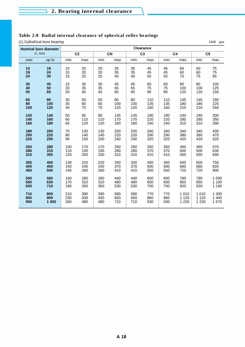
Table 2-8 Radial internal clearance of spherical roller bearings
(1) Cylindrical bore bearing Unit µm
Clearance
C2
min. max. min. max. min. max. min. max. min. max.
CN C3 C4 C5Nominal bore diameter
d, mm
over up to
14 1818 2424 30
30 4040 5050 65
65 8080 100100 120
120 140140 160160 180
180 200200 225225 250
250 280280 315315 355
355 400400 450450 500
500 560560 630630 710
710 800800 900900 1 000
10 20 20 35 35 45 45 60 60 7510 20 20 35 35 45 45 60 60 7515 25 25 40 40 55 55 75 75 95
15 30 30 45 45 60 60 80 80 10020 35 35 55 55 75 75 100 100 12520 40 40 65 65 90 90 120 120 150
30 50 50 80 80 110 110 145 145 18035 60 60 100 100 135 135 180 180 22540 75 75 120 120 160 160 210 210 260
50 95 95 145 145 190 190 240 240 30060 110 110 170 170 220 220 280 280 35065 120 120 180 180 240 240 310 310 390
70 130 130 200 200 260 260 340 340 43080 140 140 220 220 290 290 380 380 47090 150 150 240 240 320 320 420 420 520
100 170 170 260 260 350 350 460 460 570110 190 190 280 280 370 370 500 500 630120 200 200 310 310 410 410 550 550 690
130 220 220 340 340 450 450 600 600 750140 240 240 370 370 500 500 660 660 820140 260 260 410 410 550 550 720 720 900
150 280 280 440 440 600 600 780 780 1 000170 310 310 480 480 650 650 850 850 1 100190 350 350 530 530 700 700 920 920 1 190
210 390 390 580 580 770 770 1 010 1 010 1 300230 430 430 650 650 860 860 1 120 1 120 1 440260 480 480 710 710 930 930 1 220 1 220 1 570
A 19
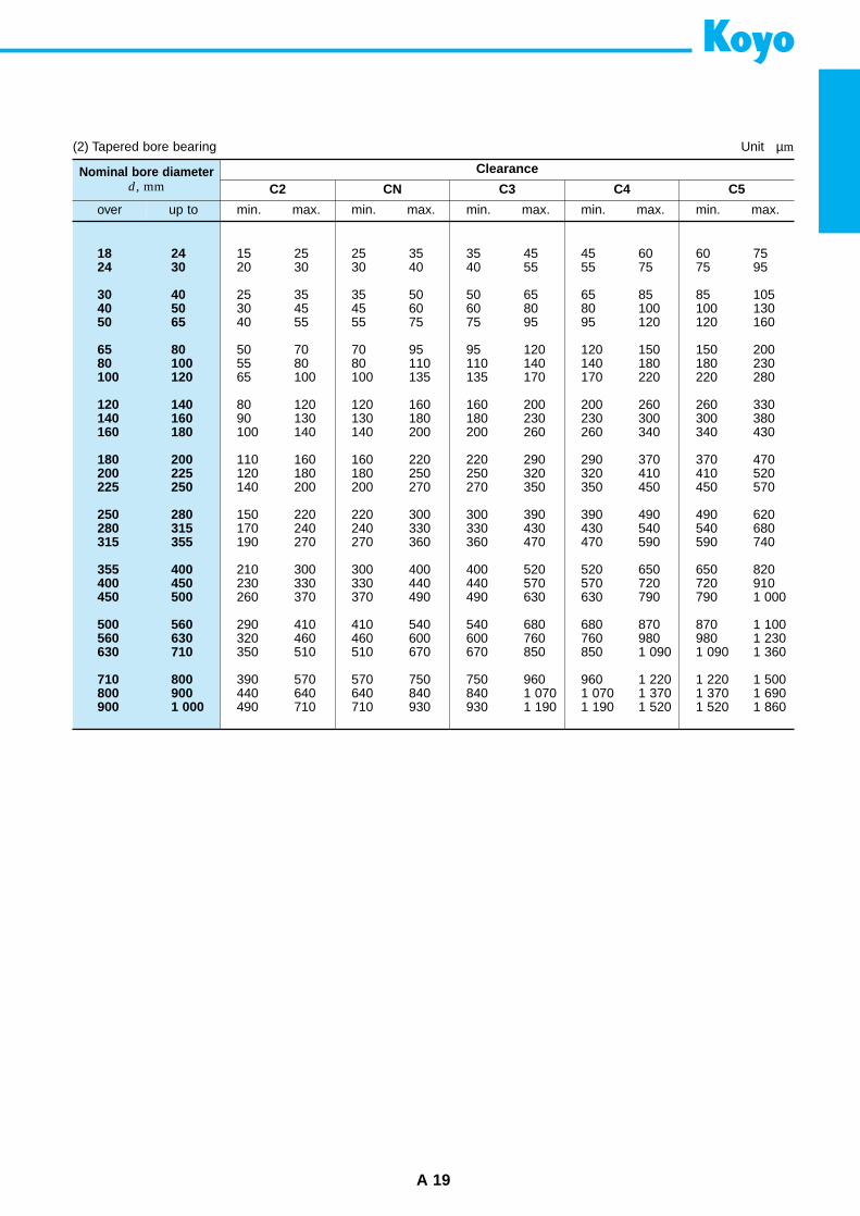
(2) Tapered bore bearing Unit µm
Clearance
C2
min. max. min. max. min. max. min. max. min. max.
CN C3 C4 C5Nominal bore diameter
d, mm
over up to
18 2424 30
30 4040 5050 65
65 8080 100100 120
120 140140 160160 180
180 200200 225225 250
250 280280 315315 355
355 400400 450450 500
500 560560 630630 710
710 800800 900900 1 000
15 25 25 35 35 45 45 60 60 7520 30 30 40 40 55 55 75 75 95
25 35 35 50 50 65 65 85 85 10530 45 45 60 60 80 80 100 100 13040 55 55 75 75 95 95 120 120 160
50 70 70 95 95 120 120 150 150 20055 80 80 110 110 140 140 180 180 23065 100 100 135 135 170 170 220 220 280
80 120 120 160 160 200 200 260 260 33090 130 130 180 180 230 230 300 300 380100 140 140 200 200 260 260 340 340 430
110 160 160 220 220 290 290 370 370 470120 180 180 250 250 320 320 410 410 520140 200 200 270 270 350 350 450 450 570
150 220 220 300 300 390 390 490 490 620170 240 240 330 330 430 430 540 540 680190 270 270 360 360 470 470 590 590 740
210 300 300 400 400 520 520 650 650 820230 330 330 440 440 570 570 720 720 910260 370 370 490 490 630 630 790 790 1 000
290 410 410 540 540 680 680 870 870 1 100320 460 460 600 600 760 760 980 980 1 230350 510 510 670 670 850 850 1 090 1 090 1 360
390 570 570 750 750 960 960 1 220 1 220 1 500440 640 640 840 840 1 070 1 070 1 370 1 370 1 690490 710 710 930 930 1 190 1 190 1 520 1 520 1 860
2. Bearing internal clearance
A 20
14 1818 2424 30
30 4040 5050 65
65 8080 100100 120
120 140140 160160 180
180 200200 225225 250
250 280280 315315 355
355 400400 450450 500
500 560560 630630 710
710 800800 900
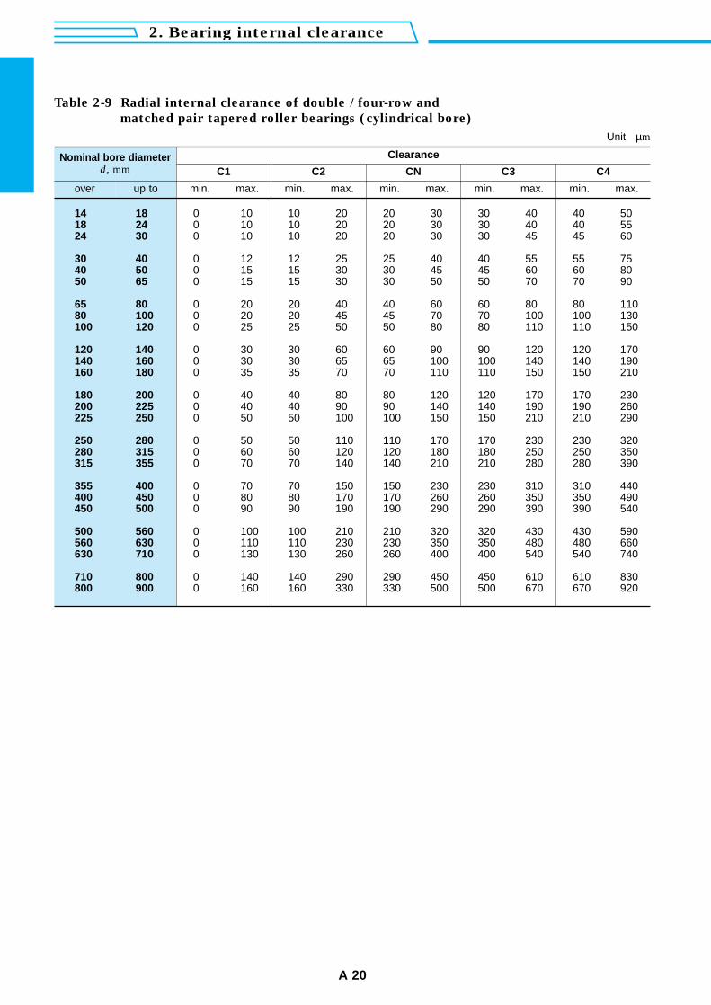
Table 2-9 Radial internal clearance of double / four-row and
matched pair tapered roller bearings (cylindrical bore)
Unit µm
Clearance
C1
min. max. min. max. min. max. min. max. min. max.
C2 CN C3 C4Nominal bore diameter
d, mm
over up to
0 10 10 20 20 30 30 40 40 500 10 10 20 20 30 30 40 40 550 10 10 20 20 30 30 45 45 60
0 12 12 25 25 40 40 55 55 750 15 15 30 30 45 45 60 60 800 15 15 30 30 50 50 70 70 90
0 20 20 40 40 60 60 80 80 1100 20 20 45 45 70 70 100 100 1300 25 25 50 50 80 80 110 110 150
0 30 30 60 60 90 90 120 120 1700 30 30 65 65 100 100 140 140 1900 35 35 70 70 110 110 150 150 210
0 40 40 80 80 120 120 170 170 2300 40 40 90 90 140 140 190 190 2600 50 50 100 100 150 150 210 210 290
0 50 50 110 110 170 170 230 230 3200 60 60 120 120 180 180 250 250 3500 70 70 140 140 210 210 280 280 390
0 70 70 150 150 230 230 310 310 4400 80 80 170 170 260 260 350 350 4900 90 90 190 190 290 290 390 390 540
0 100 100 210 210 320 320 430 430 5900 110 110 230 230 350 350 480 480 6600 130 130 260 260 400 400 540 540 740
0 140 140 290 290 450 450 610 610 8300 160 160 330 330 500 500 670 670 920
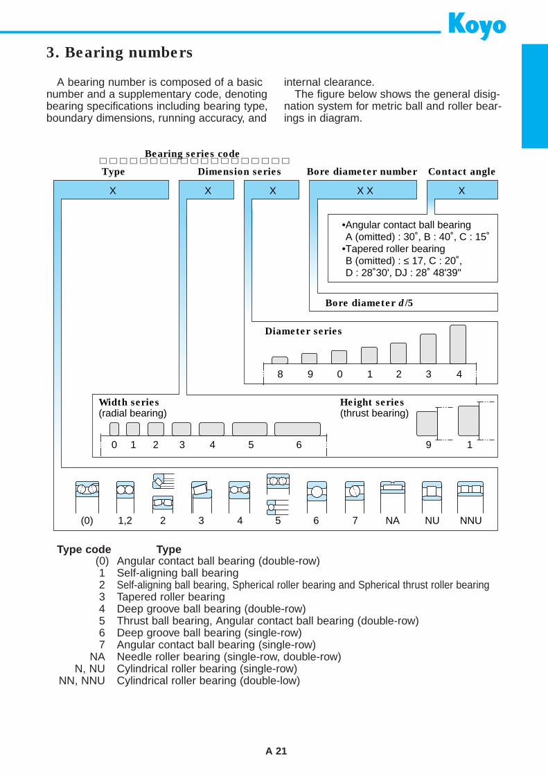
A 21
A bearing number is composed of a basicnumber and a supplementary code, denotingbearing specifications including bearing type,boundary dimensions, running accuracy, and
internal clearance.The figure below shows the general disig-
nation system for metric ball and roller bear-ings in diagram.
Type code Type(0) Angular contact ball bearing (double-row)1 Self-aligning ball bearing2 Self-aligning ball bearing, Spherical roller bearing and Spherical thrust roller bearing3 Tapered roller bearing4 Deep groove ball bearing (double-row)5 Thrust ball bearing, Angular contact ball bearing (double-row)6 Deep groove ball bearing (single-row)7 Angular contact ball bearing (single-row)
NA Needle roller bearing (single-row, double-row)N, NU Cylindrical roller bearing (single-row)
NN, NNU Cylindrical roller bearing (double-low)
3. Bearing numbers
Type Dimension series
Width series
(radial bearing)Height series
(thrust bearing)
Bearing series code
Bore diameter number
•Angular contact ball bearingA (omitted) : 30˚, B : 40˚, C : 15˚
•Tapered roller bearingB (omitted) : ≤ 17, C : 20˚,D : 28˚30', DJ : 28˚ 48'39"
Diameter series
Bore diameter d/5
Contact angle
X X X XX X
8 9 0
0
(0) 1,2 2 3 4 5 6 7 NA NU NNU
1 2 3 4 5 6 9 1
1 2 3 4
4. Handling of bearings
A 22
4-1 General instructions
Since rolling bearings are more preciselymade than other machine parts, careful handling is absolutely necessary.1) Keep bearings and the operating environ-
ment clean.2) Handle carefully.
Bearings can be cracked and brinelledeasily by strong impact if handled roughly.
3) Handle using the proper tools.4) Keep bearings well protected from rust.
Do not handle bearings in high humidity.Operators should wear gloves in order notto soil bearings with perspiration fromtheir hands.
5) Bearings should be handled by experi-enced or well trained operators.
6) Set bearing operation standards and fol-low them.• Storage of bearings• Cleaning of bearings and their adjoining
parts• Inspection of dimensions of adjoining
parts and finish conditions• Mounting• Inspection after mounting• Dismounting• Maintenance and inspection
(periodical inspection)• Replenishment of lubricants
4-2 Storage of bearings
In shipping bearings, since they are cov-ered with proper anti-corrosion oil and arewrapped in antitarnish paper, the quality ofthe bearings is guaranteed as long as thewrapping paper is not damaged.
If bearings are to be stored for a longtime, it is advisable that the bearings bestored on shelves set higher than 30 cmfrom the floor, at a humidity less than 65%,and at a temperature around 20˚C.
Avoid storage in places exposed directlyto the sun's rays or placing boxes of bear-ings against cold walls.
4-3 Bearing mounting
4-3-1 Recommended preparation prior
to mounting
1) Preparation of bearings
Wait until just before mounting before
removing the bearings from their packagingto prevent contamination and rust.
Since the anti-corrosion oil covering bear-ings is a highly capable lubricant, the oilshould not be cleaned off if the bearings arepre-lubricated, or when the bearings areused for normal operation. However, if thebearings are used in measuring instrumentsor at high rotation speed, the anti-corrosionoil should be removed using a clean deter-gent oil. After removal of the anti-corrosionoil, bearings should not be left for a longtime because they rust easily.
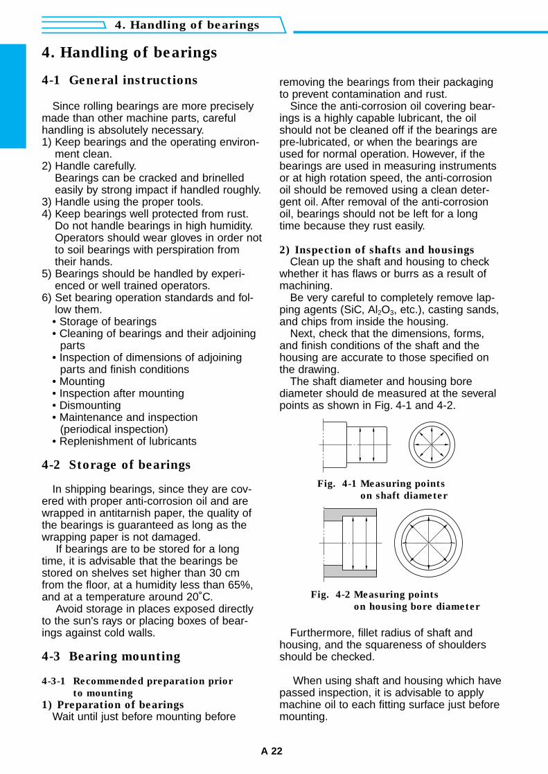
2) Inspection of shafts and housings
Clean up the shaft and housing to checkwhether it has flaws or burrs as a result ofmachining.
Be very careful to completely remove lap-ping agents (SiC, Al2O3, etc.), casting sands,and chips from inside the housing.
Next, check that the dimensions, forms,and finish conditions of the shaft and thehousing are accurate to those specified onthe drawing.
The shaft diameter and housing borediameter should de measured at the severalpoints as shown in Fig. 4-1 and 4-2.
4. Handling of bearings
Fig. 4-2 Measuring points
on housing bore diameter
Furthermore, fillet radius of shaft andhousing, and the squareness of shouldersshould be checked.
When using shaft and housing which havepassed inspection, it is advisable to applymachine oil to each fitting surface just beforemounting.
Fig. 4-1 Measuring points
on shaft diameter
A 23
Force is necessary to press fit or remove bearings
The force necessary to press fit or remove inner rings of bearings differs depending on thefinish of shafts and how much interference the bearings allow.
The standard values can be obtained by using the following equations.
(Solid shafts) Ka = 9.8ƒk · ∆ deff · B 1– ×103 ................................................... (4-1)
(Hollow shafts) Ka = 9.8ƒk · ∆ deff · B –––––––––––––––––– ×103 .................................... (4-2)
d 2
Di2
Reference
1– 1– d02
d 2
d 2
Di2
1– d02
Di2
Remark) For meaning of symbols, see page A 24.
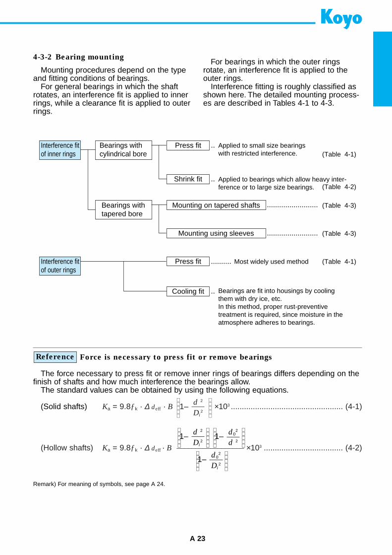
Interference fit of inner rings
Bearings with cylindrical bore
Press fit
Shrink fit
Press fit
Cooling fit
Bearings with tapered bore
Mounting on tapered shafts
Mounting using sleeves
Interference fit of outer rings
Applied to small size bearingswith restricted interference.
Applied to bearings which allow heavy inter-ference or to large size bearings.
Bearings are fit into housings by coolingthem with dry ice, etc.In this method, proper rust-preventivetreatment is required, since moisture in theatmosphere adheres to bearings.
(Table 4-1)
(Table 4-1)
(Table 4-2)
(Table 4-3)
(Table 4-3)
Most widely used method
Mounting procedures depend on the typeand fitting conditions of bearings.
For general bearings in which the shaftrotates, an interference fit is applied to innerrings, while a clearance fit is applied to outerrings.
For bearings in which the outer ringsrotate, an interference fit is applied to theouter rings.
Interference fitting is roughly classified asshown here. The detailed mounting process-es are described in Tables 4-1 to 4-3.
4-3-2 Bearing mounting
4. Handling of bearings
A 24
Table 4-1 Press fit of bearings with cylindrical bores
Mounting methods Descriptions
(a) Using press fit
(the most widely used method)
(b) Using bolts and nuts (c) Using hammers
screw hole should beprovided at the shaftend
only when there is noalternative measure
As shown in the Fig., a bearing should be mounted slowlywith care, by using a fixture to apply force evenly to thebearing.When mounting the inner ring, apply pressure to the innerring only. Similarly, in mounting the outer ring, press only theouter ring.
If interference is required onboth the inner and outer ringof nonseparable bearings,use two kinds of fixtures asshown in the Fig. and applyforce carefully, as rolling ele-ments are easily damaged.Be sure never to use a ham-mer in such cases.
Simultaneous press fit ofinner ring and outer ring
In equations (4-1) and (4-2) in page A 23.
Ka : force necessary for press fit or removal N
∆ deff : effective interference mm
ƒk : resistance coefficientCoefficient taking into consideration frictionbetween shafts and inner rings... refer to the table on the right
B : nominal inner ring width mm
d : nominal inner ring bore diameter mm
Di : average outside diameter of inner ring mm
d0 : hollow shaft bore diameter mm
Value of resistance coefficient ƒk
Conditions ƒk
• Press fitting bearings on to cylindrical shafts
• Removing bearings from cylindrical shafts
• Press fitting bearings on to tapered shafts or tapered sleeves
• Removing bearings from tapered shafts or tapered sleeves
• Press fitting tapered sleeves betweenshafts and bearings
• Removing tapered sleeves from thespace between shafts and bearings
4
6
5.5
4.5
10
11
(Hydraulic pump)
Mounting fixtureMountingfixture
Mountingfixture
Mountingfixture
Inner ring press fit Outer ring press fit Inner ring press fit

A 25
(a) Heating in an oil bath
(b) Induction heater
This photographshows a specialmachine for fitting theinner rings of cylindri-cal roller bearings.
Table 4-2 Shrink fit of cylindrical bore bearings
Shrink fit Descriptions
This method, which expands bearings by heating them in oil,has the advantage of not applying too much force to bearingsand taking only a short time.
(Notes) • Oil temperature should not be higher than 100˚C, because bearings heated at higher than 120˚C lose hardness.
• Heating temperature can be determined from the bore diameter of a bearing and the interference by referring to Fig. 4-3.
• Use nets or a lifting device to prevent the bearing from resting directly onthe bottom of the oil container.
• Since bearings shrink in the radial direction as well as the axial directionwhile cooling down, fix the inner ring and shaft shoulder tightly with theshaft nut before shrinking, so that no space is left between them.
Shrink fit proves to be clean and effective since, by this method, the ring can beprovided with even heat in a short time using neither fire nor oil.
When electricity is being conducted, the bearing itself generates heat by itselectrical resistance, aided by the built-in exciting coil.
For cylindrical roller bearings used in roll necks of rolling mills and railway rollingstock axle journals, where rings are frequently mounted and dismounted, it isadvisable for Koyo special induction heaters (with automatic demagnetizers) to beused to fit inner rings.
Remarks)1. Thick solid lines show the maximum
interference value between bearings(class 0) and shafts (r6, p6, n6, m5, k5,js5) at normal temperature.
2. Therefore, the heating temperatureshould be selected to gain a larger"expansion of the bore diameter" thanthe maximum interference velues.
When fitting class 0 bearings havinga 90 mm bore diameter to m 5shafts, this figure shows that heatingtemperature should be 40˚C higherthan room temperature to produceexpansion larger than the maximuminterference value of 48 µm.However, taking cooling duringmounting into consideration, thetemperature should be set 20 to30˚C higher than the temperatureinitially required.Fig. 4-3 Heating temperature and expansion of inner rings
Thermometer
Bore diameter d (mm)
Exp
ansi
on o
f bor
e di
amet
er (
µm)
050 80 120 180 250 315
r 6
p 6
n 6
m 5
k 5
js 5
20
40
160
140
120
100
80
60
Tem
pera
ture
diffe
renc
e
80˚C
70˚C
60˚C50˚C
40˚C
20˚C
30˚C
T =
90˚
C
∆
Special spanner
e e’
4. Handling of bearings
A 26
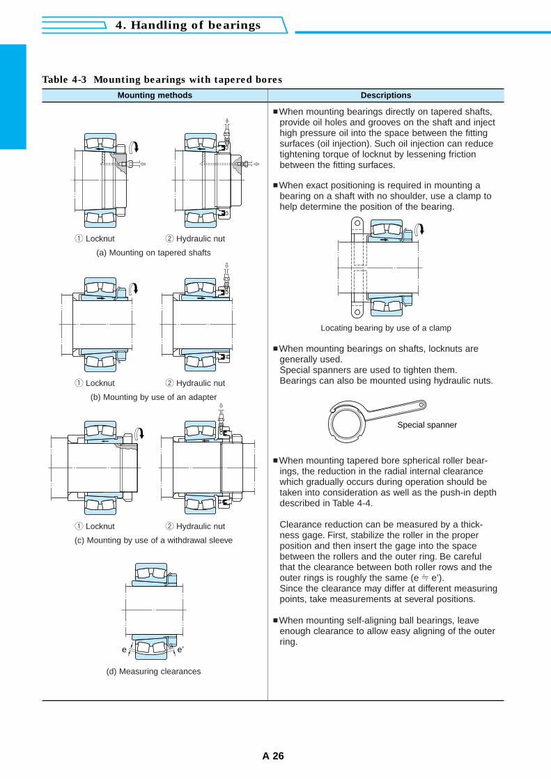
Table 4-3 Mounting bearings with tapered bores
Mounting methods Descriptions
q Locknut w Hydraulic nut
When mounting bearings directly on tapered shafts,provide oil holes and grooves on the shaft and injecthigh pressure oil into the space between the fittingsurfaces (oil injection). Such oil injection can reducetightening torque of locknut by lessening frictionbetween the fitting surfaces.
When exact positioning is required in mounting abearing on a shaft with no shoulder, use a clamp tohelp determine the position of the bearing.
(a) Mounting on tapered shafts
q Locknut w Hydraulic nut
(b) Mounting by use of an adapter
q Locknut w Hydraulic nut
(c) Mounting by use of a withdrawal sleeve
(d) Measuring clearances
Locating bearing by use of a clamp
When mounting bearings on shafts, locknuts aregenerally used.Special spanners are used to tighten them.Bearings can also be mounted using hydraulic nuts.
When mounting tapered bore spherical roller bear-ings, the reduction in the radial internal clearancewhich gradually occurs during operation should betaken into consideration as well as the push-in depthdescribed in Table 4-4.
Clearance reduction can be measured by a thick-ness gage. First, stabilize the roller in the properposition and then insert the gage into the spacebetween the rollers and the outer ring. Be carefulthat the clearance between both roller rows and theouter rings is roughly the same (e ≈ e’).Since the clearance may differ at different measuringpoints, take measurements at several positions.
When mounting self-aligning ball bearings, leaveenough clearance to allow easy aligning of the outerring.
A 27
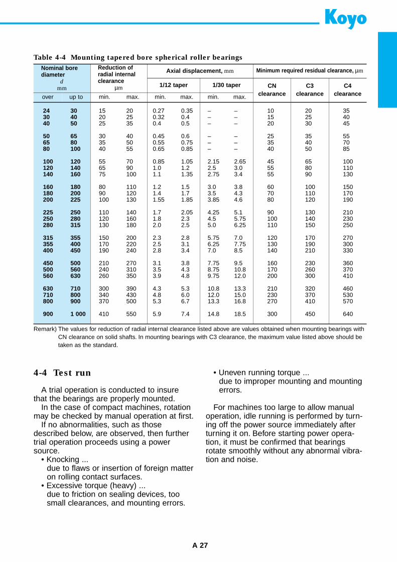
Table 4-4 Mounting tapered bore spherical roller bearings
Axial displacement, mm Minimum required residual clearance, µm
min. max. min. max. min. max.
1/12 taper 1/30 taper CNclearance
Nominal borediameter
d
mm
Reduction ofradial internalclearance
µm
over up to
24 3030 4040 50
50 6565 8080 100
100 120120 140140 160
160 180180 200200 225
225 250250 280280 315
315 355355 400400 450
450 500500 560560 630
630 710710 800800 900
900 1 000
15 20 0.27 0.35 – – 10 20 3520 25 0.32 0.4 – – 15 25 4025 35 0.4 0.5 – – 20 30 45
30 40 0.45 0.6 – – 25 35 5535 50 0.55 0.75 – – 35 40 7040 55 0.65 0.85 – – 40 50 85
55 70 0.85 1.05 2.15 2.65 45 65 10065 90 1.0 1.2 2.5 3.0 55 80 11075 100 1.1 1.35 2.75 3.4 55 90 130
80 110 1.2 1.5 3.0 3.8 60 100 15090 120 1.4 1.7 3.5 4.3 70 110 170100 130 1.55 1.85 3.85 4.6 80 120 190
110 140 1.7 2.05 4.25 5.1 90 130 210120 160 1.8 2.3 4.5 5.75 100 140 230130 180 2.0 2.5 5.0 6.25 110 150 250
150 200 2.3 2.8 5.75 7.0 120 170 270170 220 2.5 3.1 6.25 7.75 130 190 300190 240 2.8 3.4 7.0 8.5 140 210 330
210 270 3.1 3.8 7.75 9.5 160 230 360240 310 3.5 4.3 8.75 10.8 170 260 370260 350 3.9 4.8 9.75 12.0 200 300 410
300 390 4.3 5.3 10.8 13.3 210 320 460340 430 4.8 6.0 12.0 15.0 230 370 530370 500 5.3 6.7 13.3 16.8 270 410 570
410 550 5.9 7.4 14.8 18.5 300 450 640
Remark) The values for reduction of radial internal clearance listed above are values obtained when mounting bearings withCN clearance on solid shafts. In mounting bearings with C3 clearance, the maximum value listed above should betaken as the standard.
C3clearance
C4clearance
4-4 Test run
A trial operation is conducted to insurethat the bearings are properly mounted.
In the case of compact machines, rotationmay be checked by manual operation at first.
If no abnormalities, such as thosedescribed below, are observed, then furthertrial operation proceeds using a powersource.
• Knocking ...due to flaws or insertion of foreign matteron rolling contact surfaces.
• Excessive torque (heavy) ...due to friction on sealing devices, toosmall clearances, and mounting errors.
• Uneven running torque ...due to improper mounting and mountingerrors.
For machines too large to allow manualoperation, idle running is performed by turn-ing off the power source immediately afterturning it on. Before starting power opera-tion, it must be confirmed that bearingsrotate smoothly without any abnormal vibra-tion and noise.
4. Handling of bearings
A 28
Power operation should be started underno load and at low speed, then the speed isgradually increased until the designed speedis reached.
During power operation, check the noise,increase in temperature and vibration.
If any of the abnormalities listed in Tables4-5 and 4-6 are found, oparation must bestopped, and inspection for defects immedi-ately conducted.
The bearings should be dismounted ifnecessary.
Table 4-5 Bearing noises, causes, and countermeasures
Noise types Causes Countermeasures
Cyclic
Notcyclic
Others
Flaw noiseRust noiseBrinelling noise(unclear siren-like noise)
Flaw on recewayRust on racewayBrinelling on raceway
Improve mounting procedure, cleaning methodand rust preventive method. Replace bearing.
Flaking on receway Replace bearing.Flaking noise[similar to a large hammering noise]
Insertion of foreignmatter
Improve cleaning method, sealing device.Use clean lubricant. Replace bearing.
Dirt noise (an irregular sandy noise)
Improper fitting orexcessive bearingclearance
Review fitting and clearance conditions.Provide preload. Improve mounting accuracy.
Fitting noise[drumming or hammering noise]
Flaws, rust and flakingon rolling elements
Replace bearing.Flaw noise, rust noise, flaking noise
Abnormal loadIncorrect mountingInsufficient amount ofor improper lubricant
Review fitting, clearance.Adjust preload. Improve accuracy in processingand mounting shafts and housings.Improve sealing device.Refill lubricant. Select proper lubricant.
Abnormally large metallic sound
If noise is caused by improper lubrication, a proper lubricant should beselected.In general, however, serious damage will not be caused by an improperlubricant if used continuously.
Squeaknoise
similar to noise whenpunching a rivet
often heard in cylindricalroller bearings withgrease lubrication,especially in winter or atlow temperatures
Table 4-6 Causes of and countermeasures
for adnormal temperature rise
Causes
Too muchlubricant
Insufficientlubricant
Improperlubricant
Abnormalload
Impropermounting
Reduce lubricant amount.Use grease of lower consistency.
Refill lubricant.
Select proper lubricant.
Review fitting and clearance conditionsand adjust preload.
Improve accuracy on processing andmounting shaft and housing.Review fitting.Improve sealing device.
Countermeasures
Normally, listening rods are employed forbearing noise inspections.
The Koyo Bearing Checker, which detectsabnormalities through sound vibration, andthe Koyo AE Diagnosis System of Bearings,which utilizes acoustic emission for abnor-mality detection, are useful for more preciseinspection.
In general, bearing temperature can beestimated from housing temperature, but themost accurate method is to measure thetemperature of outer rings directly via lubri-cation holes.
Normally, bearing temperature begins torise gradually when operation is just starting;and, unless the bearing has some abnormal-ity, the temperature stabilizes within one ortwo hours.
Therefore, a rapid rise in temperature orunusually high temperature indicates someabnormality.
excessivefriction
Fixtures
Removal jaws
A 29
4-5 Bearing dismounting
After dismounting bearings, handling ofthe bearings and the various methods avail-able for this should be considered.
If the bearing is to be disposed of, anysimple method such as torch cutting can beemployed. If the bearing is to be reused orchecked for the causes of its failure, thesame amount of care as in mounting shouldbe taken in dismounting so as not to dam-age the bearing and other parts.
Since bearings with interference fits areeasily damaged during dismounting, mea-sures to prevent damage during dismountingmust be incorporated into the design.
It is recommended that dismountingdevices be designed and manufactured, ifnecessary.
It is useful for discovering the causes offailures when the conditions of bearings,including mounting direction and location,are recorded prior to dismounting.
Dismounting method
Tables 4-7 to 4-9 describe dismountingmethods for interference fit bearings intend-ed for reuse or for failure analysis.
The force necessary to remove bearingscan be calculated using the equations givenon page A 23.
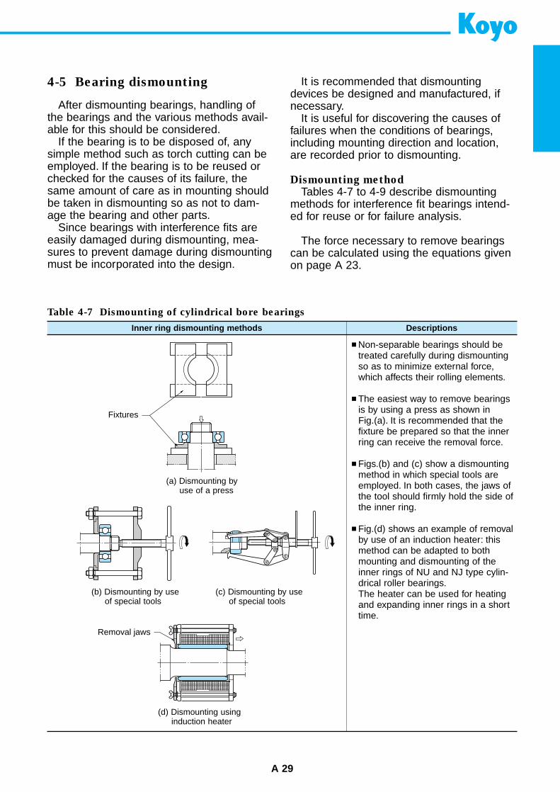
Table 4-7 Dismounting of cylindrical bore bearings
Inner ring dismounting methods Descriptions
Non-separable bearings should betreated carefully during dismountingso as to minimize external force,which affects their rolling elements.
The easiest way to remove bearingsis by using a press as shown inFig.(a). It is recommended that thefixture be prepared so that the innerring can receive the removal force.
Figs.(b) and (c) show a dismountingmethod in which special tools areemployed. In both cases, the jaws ofthe tool should firmly hold the side ofthe inner ring.
Fig.(d) shows an example of removalby use of an induction heater: thismethod can be adapted to bothmounting and dismounting of theinner rings of NU and NJ type cylin-drical roller bearings.The heater can be used for heatingand expanding inner rings in a shorttime.
(a) Dismounting byuse of a press
(b) Dismounting by useof special tools
(c) Dismounting by useof special tools
(d) Dismounting usinginduction heater
4. Handling of bearings
A 30
Table 4-8 Dismounting tapered bore bearings
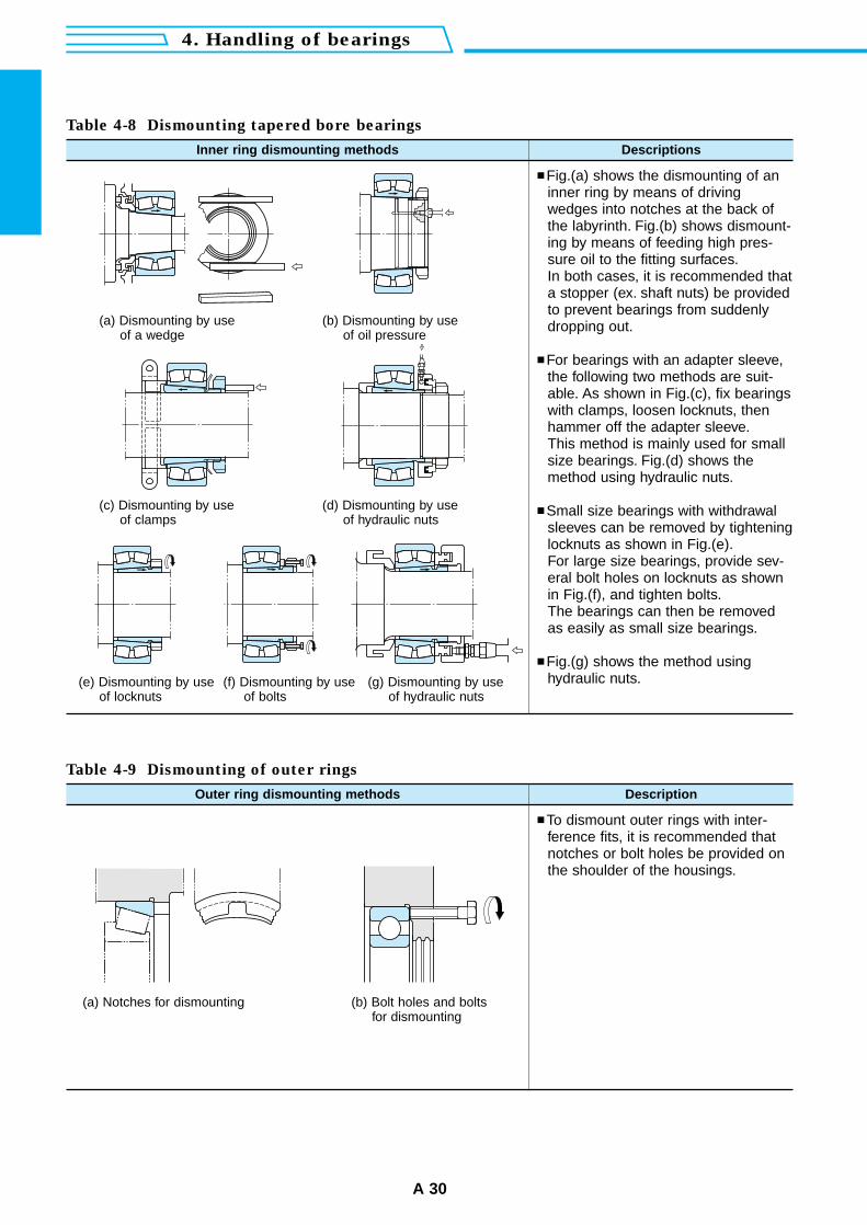
Inner ring dismounting methods Descriptions
Fig.(a) shows the dismounting of aninner ring by means of drivingwedges into notches at the back ofthe labyrinth. Fig.(b) shows dismount-ing by means of feeding high pres-sure oil to the fitting surfaces.In both cases, it is recommended thata stopper (ex. shaft nuts) be providedto prevent bearings from suddenlydropping out.
For bearings with an adapter sleeve,the following two methods are suit-able. As shown in Fig.(c), fix bearingswith clamps, loosen locknuts, thenhammer off the adapter sleeve.This method is mainly used for smallsize bearings. Fig.(d) shows themethod using hydraulic nuts.
Small size bearings with withdrawalsleeves can be removed by tighteninglocknuts as shown in Fig.(e).For large size bearings, provide sev-eral bolt holes on locknuts as shownin Fig.(f), and tighten bolts.The bearings can then be removedas easily as small size bearings.
Fig.(g) shows the method usinghydraulic nuts.
Table 4-9 Dismounting of outer rings
Outer ring dismounting methods Description
To dismount outer rings with inter-ference fits, it is recommended thatnotches or bolt holes be provided onthe shoulder of the housings.
(a) Dismounting by useof a wedge
(b) Dismounting by useof oil pressure
(e) Dismounting by useof locknuts
(f) Dismounting by useof bolts
(g) Dismounting by useof hydraulic nuts
(c) Dismounting by useof clamps
(d) Dismounting by useof hydraulic nuts
(a) Notches for dismounting (b) Bolt holes and boltsfor dismounting
A 31
4-6 Maintenance and inspection of bearings
Periodic and thorough maintenance andinspection are indispensable to drawing fullperformance from bearings and lengtheningtheir useful life.
Besides, prevention of accidents and downtime by early detection of failures throughmaintenance and inspection greatly con-tributes to the enhancement of productivityand profitability.
4-6-1 Cleaning
Before dismounting a bearing for inspec-tion, record the physical condition of thebearing, including taking photographs.
Cleaning should be done after checkingthe amount of remaining lubricant and col-lecting lubricant as a sample for examina-tion.
• A dirty bearing should be cleaned usingtwo cleaning processes, such as roughcleaning and finish cleaning.It is recommended that a net be set on thebottom of cleaning containers.
• In rough cleaning, use brushes to removegrease and dirt. Bearings should be han-dled carefully. Note that raceway surfacesmay be damaged by foreign matter, if bear-ings are rotated in cleaning oil.
• During finish cleaning, clean bearings care-fully by rotating them slowly in cleaning oil.
In general, neutral water-free light oil orkerosene is used to clean bearings, a warmalkali solution can also be used if necessary.In any case, it is essential to keep oil cleanby filtering it prior to cleaning.
Apply anti-corrosion oil or rust preventivegrease on bearings immediately after clean-ing.
4-6-2 Inspection and analysis
Before determining that dismounted bear-ings will be reused, the accuracy of theirdimensions and running, internal clearance,fitting surfaces, raceways, rolling contact sur-faces, cages and seals must be carefullyexamined, so as to confirm that no abnor-mality is present.
It is desirable for skilled persons who havesufficient knowledge of bearings to makedecisions on the reuse of bearings.
Criteria for reuse differs according to theperformance and importance of machinesand inspection frequency.
If the following defects are found, replacethe bearing with a new one.• Cracks and chips in bearing components• Flaking on the raceway surfaces and the
rolling contact surfaces• Other failures of a serious degree
4-7 Methods of analyzing bearingfailures
It is important for enhancing productivityand profitability, as well as for accident pre-vention that abnormalities in bearings aredetected during operation.
Representative detection methods aredescribed in the following section.
1) Noise checking
Since the detection of abnormalities inbearings from noises requires ample experi-ence, sufficient training must be given toinspectors. Given this, it is recommendedthat specific persons be assigned to thiswork in order to gain this experience.
Attaching hearing aids or listening rods onhousings is effective for detecting bearingnoise.
2) Checking of operating temperature
Since this method utilizes change in oper-ating temperature, its application is limited torelatively stable operations.
For detection, operating temperaturesmust be continuously recorded.
If abnormalities occur in bearings, operat-ing temperature not only increase but alsochange irregularly.
It is recommended that this method beemployed together with noise checking.
3) Lubricant checking
This method detects abnormalities fromthe foreign matter, including dirt and metallicpowder, in lubricants collected as samples.
This method is recommended for inspec-tion of bearings which cannot be checked byclose visual inspection, and large size bear-ings.
B 1
Bearing specification tables
Contents
Deep groove ball bearings .............. B 2
Single-row
Open / shielded / sealed type ............. B 6
Snap ring groove / lacating snap ring type .. B12
Extra-small, miniature ball bearings
Open / shielded / sealed type ............. B14
Double-row ............................................. B15
Angular contact ball bearings ....... B16
Single-row ............................................... B24
Double-row ............................................. B32
Self-aligning ball bearings .............. B34
Open / sealed type ................................. B36
Adapter assemblies ................................ B40
Cylindrical roller bearings ............... B42
Tapered roller bearings .................... B50
Metric series ........................................... B54
Inch series .............................................. B60
Spherical roller bearings ................. B70
Spherical roller bearings ......................... B74
Adapter assemblies ................................ B82
Thrust ball bearings .......................... B88
Spherical thrust roller bearings .... B94
Ball bearing units ............................. B 98
Pillow block type
Set screw locking .............................. B104
Adapter locking ................................. B106
Thick section pillow block type ............. B108
Rhombic-flanged type ........................... B110
Square-flanged type ............................. B112
Round-flanged type with spigot joint .... B114
Square-flanged type with spigot joint ... B116
Take-up type ......................................... B118
Cartridge type ....................................... B120
Light duty .............................................. B121
"Clean" series ....................................... B123
Pressed steel housing units ................. B125
Ball bearings for units
Cylindrical bore type (set screw locking) .. B128
Tapered bore type (adapter locking) .. B130
Locknuts and lockwashers ........... B132
Locknuts ............................................... B134
Lockwashers ......................................... B137
B 3
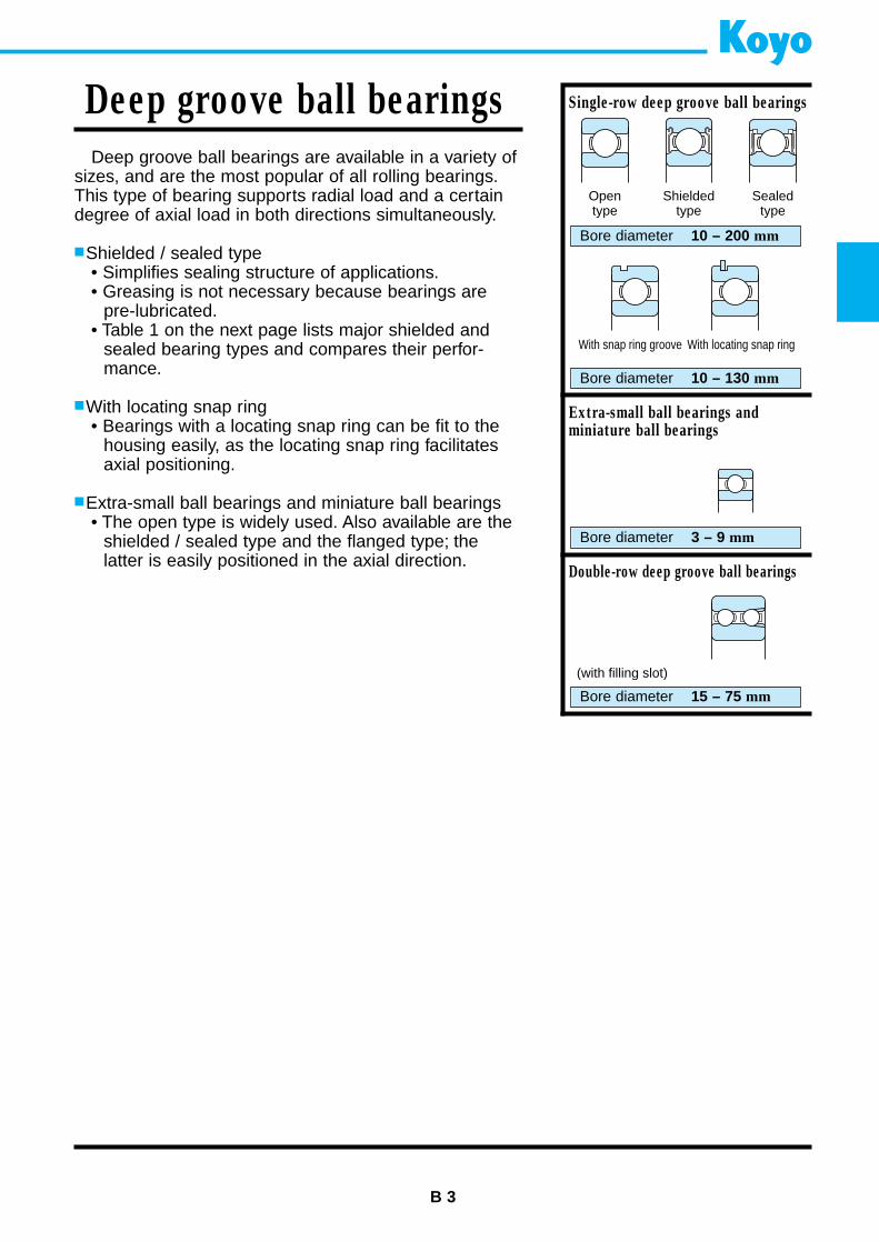
Deep groove ball bearings
Deep groove ball bearings are available in a variety ofsizes, and are the most popular of all rolling bearings.This type of bearing supports radial load and a certaindegree of axial load in both directions simultaneously.
Shielded / sealed type• Simplifies sealing structure of applications.• Greasing is not necessary because bearings are
pre-lubricated.• Table 1 on the next page lists major shielded and
sealed bearing types and compares their perfor-mance.
With locating snap ring• Bearings with a locating snap ring can be fit to the
housing easily, as the locating snap ring facilitatesaxial positioning.
Extra-small ball bearings and miniature ball bearings• The open type is widely used. Also available are the
shielded / sealed type and the flanged type; the latter is easily positioned in the axial direction.
Single-row deep groove ball bearings
Bore diameter 10 – 200 mm
Extra-small ball bearings and miniature ball bearings
Bore diameter 3 – 9 mm
Double-row deep groove ball bearings
Bore diameter 15 – 75 mm
Bore diameter 10 – 130 mm
Opentype
Shieldedtype
Sealedtype
With snap ring groove With locating snap ring
(with filling slot)
B 4
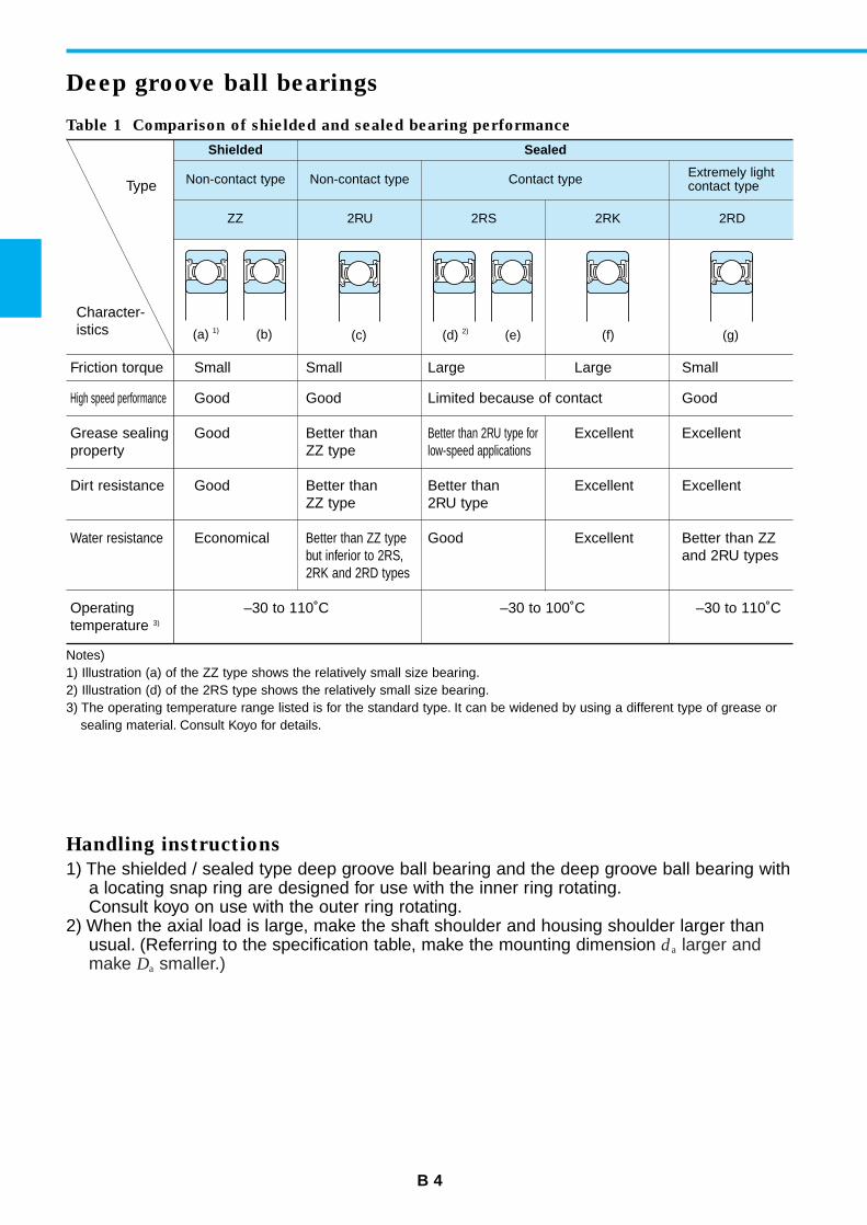
Deep groove ball bearings
Table 1 Comparison of shielded and sealed bearing performance
Shielded
Friction torque Small Small Large Large Small
High speed performance Good Good Limited because of contact Good
Grease sealing Good Better than Better than 2RU type for Excellent Excellentproperty ZZ type low-speed applications
Dirt resistance Good Better than Better than Excellent ExcellentZZ type 2RU type
Water resistance Economical Better than ZZ type Good Excellent Better than ZZ but inferior to 2RS, and 2RU types2RK and 2RD types
Operating –30 to 110˚C –30 to 100˚C –30 to 110˚Ctemperature 3)
Non-contact type Non-contact type Contact type Extremely lightcontact type
ZZ 2RU 2RS 2RK 2RD
Sealed
Type
Character-istics
Notes)1) Illustration (a) of the ZZ type shows the relatively small size bearing.2) Illustration (d) of the 2RS type shows the relatively small size bearing.3) The operating temperature range listed is for the standard type. It can be widened by using a different type of grease or
sealing material. Consult Koyo for details.
Handling instructions
1) The shielded / sealed type deep groove ball bearing and the deep groove ball bearing witha locating snap ring are designed for use with the inner ring rotating.Consult koyo on use with the outer ring rotating.
2) When the axial load is large, make the shaft shoulder and housing shoulder larger thanusual. (Referring to the specification table, make the mounting dimension da larger andmake Da smaller.)
(a) 1) (b) (c) (d) 2) (e) (f) (g)
B 5
The dimensions of standard series are as specified in JIS B 1512.For extra-small and miniature ball bearings, special series (ML) are specifiedtogether with those described above.
As specified in JIS B 1514.
Deep groove ball bearings (except extra-small ball bearings and miniature ballbearings) ....................... as specified in JIS B 1520 (refer to Table 2-1 on p. A11.)
Extra-small ball bearings and miniature ball bearings...................... (refer to Table 2-2 on p. A11.)
Deep groove ball bearings for motors ...................... (refer to Table 2-6 on p. A14.)
• Pressed steel cage(supplementary code : //)
• Copper alloy machinedcage(supplementary code : FY)
Remark :For certain applications,stainless steel sheetpressed cages (YS) andpolyamide molded cages(MG) may also be used.
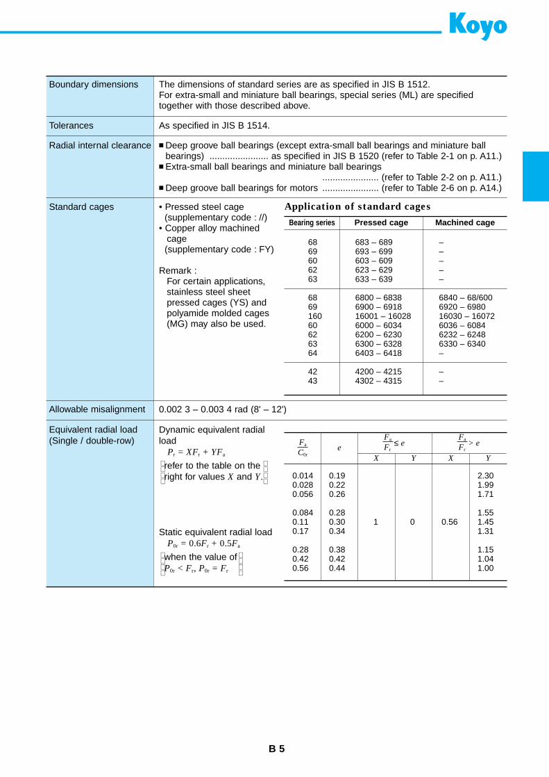
Boundary dimensions
Tolerances
Radial internal clearance
Standard cages
Allowable misalignment
Equivalent radial load(Single / double-row)
Application of standard cages
Bearing series Pressed cage Machined cage
68 683 – 689 –69 693 – 699 –60 603 – 609 –62 623 – 629 –63 633 – 639 –
68 6800 – 6838 6840 – 68/60069 6900 – 6918 6920 – 6980160 16001 – 16028 16030 – 1607260 6000 – 6034 6036 – 608462 6200 – 6230 6232 – 624863 6300 – 6328 6330 – 634064 6403 – 6418 –
42 4200 – 4215 –43 4302 – 4315 –
Fa
C0re
Fa
Fr ≤ e
X Y X Y
Fa
Fr > e
0.014 0.19 2.300.028 0.22 1.990.056 0.26 1.71
0.084 0.28 1.550.11 0.30 1 0 0.56 1.450.17 0.34 1.31
0.28 0.38 1.150.42 0.42 1.040.56 0.44 1.00
0.002 3 – 0.003 4 rad (8' – 12')
Dynamic equivalent radialload
Pr = XFr + YFa
refer to the table on theright for values X and Y.
Static equivalent radial loadP0r = 0.6Fr + 0.5Fa
when the value ofP0r < Fr, P0r = Fr
Single-row deep groove ball bearings
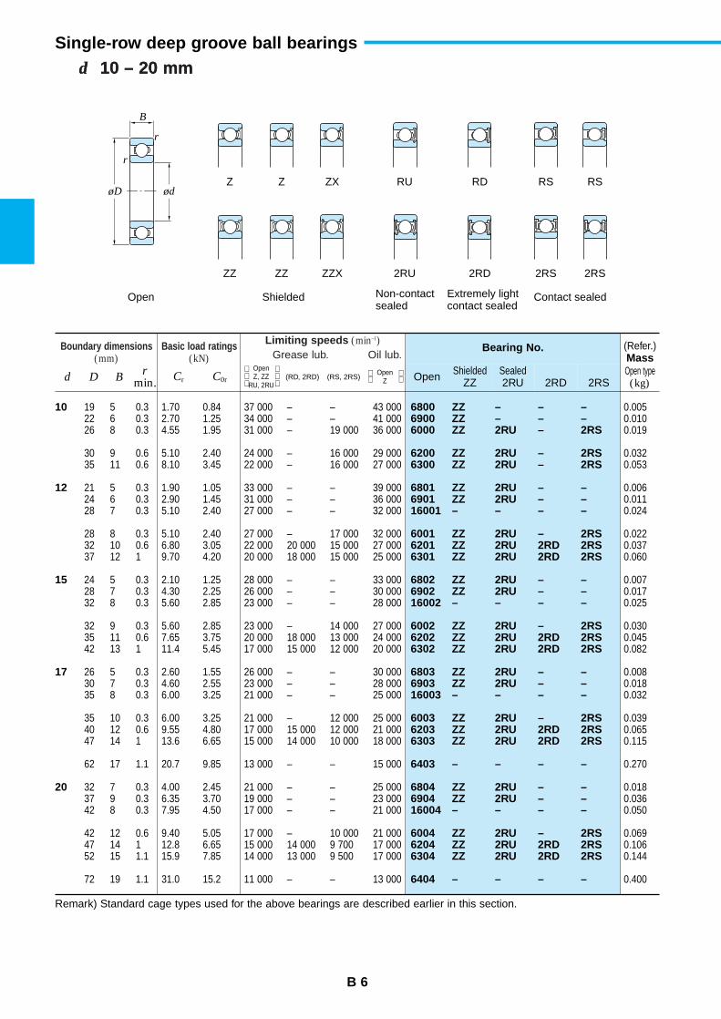
B 6
d 10 – 20 mmd 10 – 20 mm
Boundary dimensions(mm)
Basic load ratings(kN)
Limiting speeds (min–1)Grease lub. Oil lub.
Bearing No. (Refer.)Mass
d D Br
min. Cr C0r Open ShieldedZZ
Sealed2RU 2RD 2RS
Open type(kg)
Open Z, ZZ RU, 2RU
(RD, 2RD) (RS, 2RS) Open Z
10
12
15
17
20
6800 ZZ – – –6900 ZZ – – –6000 ZZ 2RU – 2RS
6200 ZZ 2RU – 2RS6300 ZZ 2RU – 2RS
6801 ZZ 2RU – –6901 ZZ 2RU – –16001 – – – –
6001 ZZ 2RU – 2RS6201 ZZ 2RU 2RD 2RS6301 ZZ 2RU 2RD 2RS
6802 ZZ 2RU – –6902 ZZ 2RU – –16002 – – – –
6002 ZZ 2RU – 2RS6202 ZZ 2RU 2RD 2RS6302 ZZ 2RU 2RD 2RS
6803 ZZ 2RU – –6903 ZZ 2RU – –16003 – – – –
6003 ZZ 2RU – 2RS6203 ZZ 2RU 2RD 2RS6303 ZZ 2RU 2RD 2RS
6403 – – – –
6804 ZZ 2RU – –6904 ZZ 2RU – –16004 – – – –
6004 ZZ 2RU – 2RS6204 ZZ 2RU 2RD 2RS6304 ZZ 2RU 2RD 2RS
6404 – – – –
19 5 0.3 1.70 0.84 37 000 – – 43 00022 6 0.3 2.70 1.25 34 000 – – 41 00026 8 0.3 4.55 1.95 31 000 – 19 000 36 000
30 9 0.6 5.10 2.40 24 000 – 16 000 29 00035 11 0.6 8.10 3.45 22 000 – 16 000 27 000
21 5 0.3 1.90 1.05 33 000 – – 39 00024 6 0.3 2.90 1.45 31 000 – – 36 00028 7 0.3 5.10 2.40 27 000 – – 32 000
28 8 0.3 5.10 2.40 27 000 – 17 000 32 00032 10 0.6 6.80 3.05 22 000 20 000 15 000 27 00037 12 1 9.70 4.20 20 000 18 000 15 000 25 000
24 5 0.3 2.10 1.25 28 000 – – 33 00028 7 0.3 4.30 2.25 26 000 – – 30 00032 8 0.3 5.60 2.85 23 000 – – 28 000
32 9 0.3 5.60 2.85 23 000 – 14 000 27 00035 11 0.6 7.65 3.75 20 000 18 000 13 000 24 00042 13 1 11.4 5.45 17 000 15 000 12 000 20 000
26 5 0.3 2.60 1.55 26 000 – – 30 00030 7 0.3 4.60 2.55 23 000 – – 28 00035 8 0.3 6.00 3.25 21 000 – – 25 000
35 10 0.3 6.00 3.25 21 000 – 12 000 25 00040 12 0.6 9.55 4.80 17 000 15 000 12 000 21 00047 14 1 13.6 6.65 15 000 14 000 10 000 18 000
62 17 1.1 20.7 9.85 13 000 – – 15 000
32 7 0.3 4.00 2.45 21 000 – – 25 00037 9 0.3 6.35 3.70 19 000 – – 23 00042 8 0.3 7.95 4.50 17 000 – – 21 000
42 12 0.6 9.40 5.05 17 000 – 10 000 21 00047 14 1 12.8 6.65 15 000 14 000 9 700 17 00052 15 1.1 15.9 7.85 14 000 13 000 9 500 17 000
72 19 1.1 31.0 15.2 11 000 – – 13 000
0.0050.0100.019
0.0320.053
0.0060.0110.024
0.0220.0370.060
0.0070.0170.025
0.0300.0450.082
0.0080.0180.032
0.0390.0650.115
0.270
0.0180.0360.050
0.0690.1060.144
0.400
Remark) Standard cage types used for the above bearings are described earlier in this section.
B
r
r
øD ødZ Z ZX RU RD RS RS
ZZ ZZ ZZX 2RU 2RD 2RS 2RS
Open Shielded Non-contactsealed
Extremely lightcontact sealed
Contact sealed
Boundary dimensions(mm)
Basic load ratings(kN)
Limiting speeds (min–1)Grease lub. Oil lub.
Bearing No. (Refer.)Mass
d D Br
min. Cr C0r Open ShieldedZZ
Sealed2RU 2RD 2RS
Open type(kg)
Open Z, ZZ RU, 2RU
(RD, 2RD) (RS, 2RS) Open Z
B 7
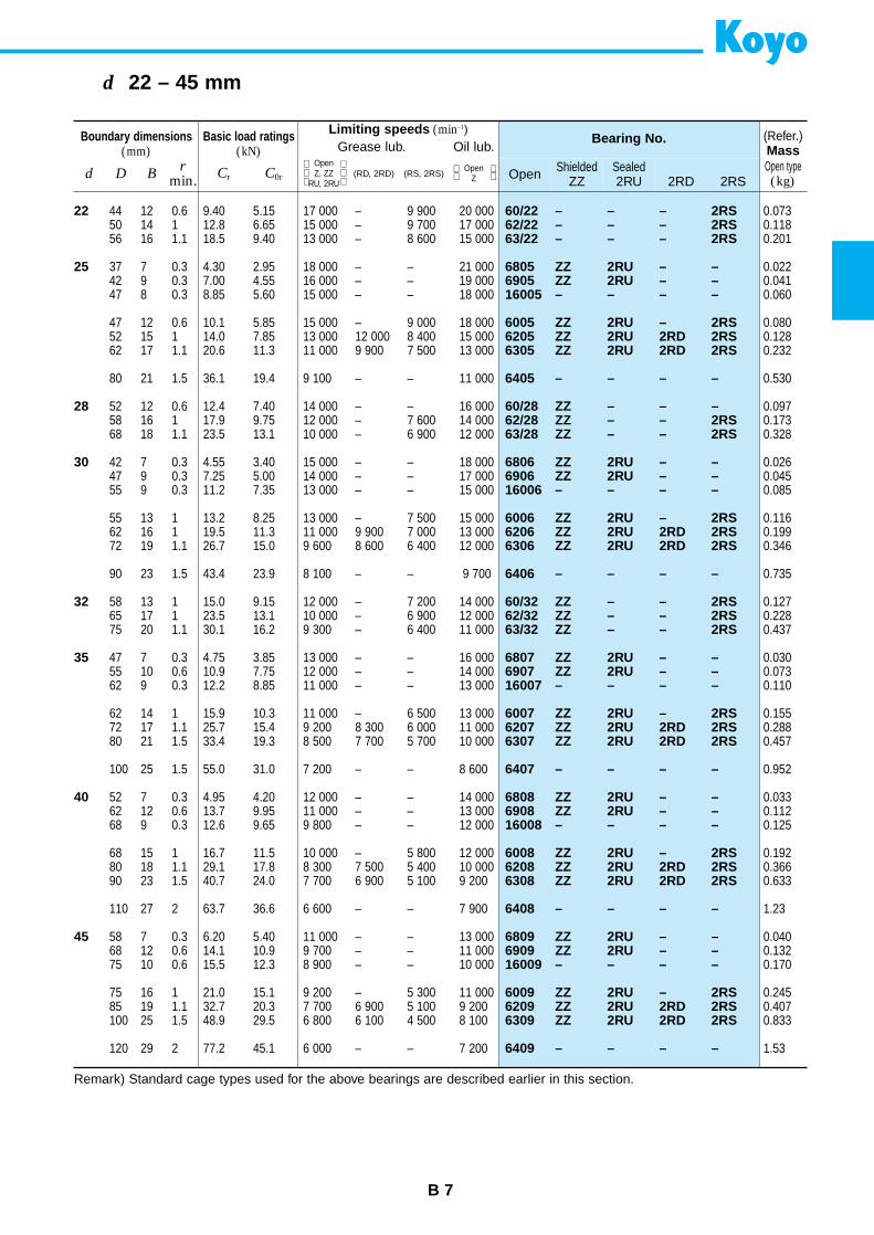
d 22 – 45 mm
22
25
28
30
32
35
40
45
60/22 – – – 2RS62/22 – – – 2RS63/22 – – – 2RS
6805 ZZ 2RU – –6905 ZZ 2RU – –16005 – – – –
6005 ZZ 2RU – 2RS6205 ZZ 2RU 2RD 2RS6305 ZZ 2RU 2RD 2RS
6405 – – – –
60/28 ZZ – – –62/28 ZZ – – 2RS63/28 ZZ – – 2RS
6806 ZZ 2RU – –6906 ZZ 2RU – –16006 – – – –
6006 ZZ 2RU – 2RS6206 ZZ 2RU 2RD 2RS6306 ZZ 2RU 2RD 2RS
6406 – – – –
60/32 ZZ – – 2RS62/32 ZZ – – 2RS63/32 ZZ – – 2RS
6807 ZZ 2RU – –6907 ZZ 2RU – –16007 – – – –
6007 ZZ 2RU – 2RS6207 ZZ 2RU 2RD 2RS6307 ZZ 2RU 2RD 2RS
6407 – – – –
6808 ZZ 2RU – –6908 ZZ 2RU – –16008 – – – –
6008 ZZ 2RU – 2RS6208 ZZ 2RU 2RD 2RS6308 ZZ 2RU 2RD 2RS
6408 – – – –
6809 ZZ 2RU – –6909 ZZ 2RU – –16009 – – – –
6009 ZZ 2RU – 2RS6209 ZZ 2RU 2RD 2RS6309 ZZ 2RU 2RD 2RS
6409 – – – –
44 12 0.6 9.40 5.15 17 000 – 9 900 20 00050 14 1 12.8 6.65 15 000 – 9 700 17 00056 16 1.1 18.5 9.40 13 000 – 8 600 15 000
37 7 0.3 4.30 2.95 18 000 – – 21 00042 9 0.3 7.00 4.55 16 000 – – 19 00047 8 0.3 8.85 5.60 15 000 – – 18 000
47 12 0.6 10.1 5.85 15 000 – 9 000 18 00052 15 1 14.0 7.85 13 000 12 000 8 400 15 00062 17 1.1 20.6 11.3 11 000 9 900 7 500 13 000
80 21 1.5 36.1 19.4 9 100 – – 11 000
52 12 0.6 12.4 7.40 14 000 – – 16 00058 16 1 17.9 9.75 12 000 – 7 600 14 00068 18 1.1 23.5 13.1 10 000 – 6 900 12 000
42 7 0.3 4.55 3.40 15 000 – – 18 00047 9 0.3 7.25 5.00 14 000 – – 17 00055 9 0.3 11.2 7.35 13 000 – – 15 000
55 13 1 13.2 8.25 13 000 – 7 500 15 00062 16 1 19.5 11.3 11 000 9 900 7 000 13 00072 19 1.1 26.7 15.0 9 600 8 600 6 400 12 000
90 23 1.5 43.4 23.9 8 100 – – 9 700
58 13 1 15.0 9.15 12 000 – 7 200 14 00065 17 1 23.5 13.1 10 000 – 6 900 12 00075 20 1.1 30.1 16.2 9 300 – 6 400 11 000
47 7 0.3 4.75 3.85 13 000 – – 16 00055 10 0.6 10.9 7.75 12 000 – – 14 00062 9 0.3 12.2 8.85 11 000 – – 13 000
62 14 1 15.9 10.3 11 000 – 6 500 13 00072 17 1.1 25.7 15.4 9 200 8 300 6 000 11 00080 21 1.5 33.4 19.3 8 500 7 700 5 700 10 000
100 25 1.5 55.0 31.0 7 200 – – 8 600
52 7 0.3 4.95 4.20 12 000 – – 14 00062 12 0.6 13.7 9.95 11 000 – – 13 00068 9 0.3 12.6 9.65 9 800 – – 12 000
68 15 1 16.7 11.5 10 000 – 5 800 12 00080 18 1.1 29.1 17.8 8 300 7 500 5 400 10 00090 23 1.5 40.7 24.0 7 700 6 900 5 100 9 200
110 27 2 63.7 36.6 6 600 – – 7 900
58 7 0.3 6.20 5.40 11 000 – – 13 00068 12 0.6 14.1 10.9 9 700 – – 11 00075 10 0.6 15.5 12.3 8 900 – – 10 000
75 16 1 21.0 15.1 9 200 – 5 300 11 00085 19 1.1 32.7 20.3 7 700 6 900 5 100 9 200100 25 1.5 48.9 29.5 6 800 6 100 4 500 8 100
120 29 2 77.2 45.1 6 000 – – 7 200
0.0730.1180.201
0.0220.0410.060
0.0800.1280.232
0.530
0.0970.1730.328
0.0260.0450.085
0.1160.1990.346
0.735
0.1270.2280.437
0.0300.0730.110
0.1550.2880.457
0.952
0.0330.1120.125
0.1920.3660.633
1.23
0.0400.1320.170
0.2450.4070.833
1.53
Remark) Standard cage types used for the above bearings are described earlier in this section.
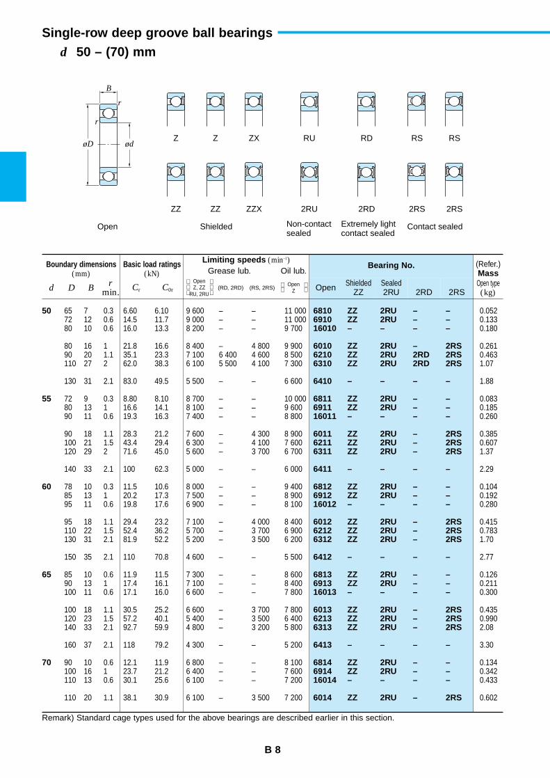
Single-row deep groove ball bearings
B 8
d 50 – (70) mm
Boundary dimensions(mm)
Basic load ratings(kN)
Limiting speeds (min–1)Grease lub. Oil lub.
Bearing No. (Refer.)Mass
d D Br
min. Cr C0r Open ShieldedZZ
Sealed2RU 2RD 2RS
Open type(kg)
Open Z, ZZ RU, 2RU
(RD, 2RD) (RS, 2RS) Open Z
50
55
60
65
70
6810 ZZ 2RU – –6910 ZZ 2RU – –16010 – – – –
6010 ZZ 2RU – 2RS6210 ZZ 2RU 2RD 2RS6310 ZZ 2RU 2RD 2RS
6410 – – – –
6811 ZZ 2RU – –6911 ZZ 2RU – –16011 – – – –
6011 ZZ 2RU – 2RS6211 ZZ 2RU – 2RS6311 ZZ 2RU – 2RS
6411 – – – –
6812 ZZ 2RU – –6912 ZZ 2RU – –16012 – – – –
6012 ZZ 2RU – 2RS6212 ZZ 2RU – 2RS6312 ZZ 2RU – 2RS
6412 – – – –
6813 ZZ 2RU – –6913 ZZ 2RU – –16013 – – – –
6013 ZZ 2RU – 2RS6213 ZZ 2RU – 2RS6313 ZZ 2RU – 2RS
6413 – – – –
6814 ZZ 2RU – –6914 ZZ 2RU – –16014 – – – –
6014 ZZ 2RU – 2RS
65 7 0.3 6.60 6.10 9 600 – – 11 00072 12 0.6 14.5 11.7 9 000 – – 11 00080 10 0.6 16.0 13.3 8 200 – – 9 700
80 16 1 21.8 16.6 8 400 – 4 800 9 90090 20 1.1 35.1 23.3 7 100 6 400 4 600 8 500110 27 2 62.0 38.3 6 100 5 500 4 100 7 300
130 31 2.1 83.0 49.5 5 500 – – 6 600
72 9 0.3 8.80 8.10 8 700 – – 10 00080 13 1 16.6 14.1 8 100 – – 9 60090 11 0.6 19.3 16.3 7 400 – – 8 800
90 18 1.1 28.3 21.2 7 600 – 4 300 8 900100 21 1.5 43.4 29.4 6 300 – 4 100 7 600120 29 2 71.6 45.0 5 600 – 3 700 6 700
140 33 2.1 100 62.3 5 000 – – 6 000
78 10 0.3 11.5 10.6 8 000 – – 9 40085 13 1 20.2 17.3 7 500 – – 8 90095 11 0.6 19.8 17.6 6 900 – – 8 100
95 18 1.1 29.4 23.2 7 100 – 4 000 8 400110 22 1.5 52.4 36.2 5 700 – 3 700 6 900130 31 2.1 81.9 52.2 5 200 – 3 500 6 200
150 35 2.1 110 70.8 4 600 – – 5 500
85 10 0.6 11.9 11.5 7 300 – – 8 60090 13 1 17.4 16.1 7 100 – – 8 400100 11 0.6 17.1 16.0 6 600 – – 7 800
100 18 1.1 30.5 25.2 6 600 – 3 700 7 800120 23 1.5 57.2 40.1 5 400 – 3 500 6 400140 33 2.1 92.7 59.9 4 800 – 3 200 5 800
160 37 2.1 118 79.2 4 300 – – 5 200
90 10 0.6 12.1 11.9 6 800 – – 8 100100 16 1 23.7 21.2 6 400 – – 7 600110 13 0.6 30.1 25.6 6 100 – – 7 200
110 20 1.1 38.1 30.9 6 100 – 3 500 7 200
0.0520.1330.180
0.2610.4631.07
1.88
0.0830.1850.260
0.3850.6071.37
2.29
0.1040.1920.280
0.4150.7831.70
2.77
0.1260.2110.300
0.4350.9902.08
3.30
0.1340.3420.433
0.602
Remark) Standard cage types used for the above bearings are described earlier in this section.
B
r
r
øD ødZ Z ZX RU RD RS RS
ZZ ZZ ZZX 2RU 2RD 2RS 2RS
Open Shielded Non-contactsealed
Extremely lightcontact sealed
Contact sealed
B 9
d (70) – 105 mm
Boundary dimensions(mm)
Basic load ratings(kN)
Limiting speeds (min–1)Grease lub. Oil lub.
Bearing No. (Refer.)Mass
d D Br
min. Cr C0r Open ShieldedZZ
Sealed2RU 2RD 2RS
Open type(kg)
Open Z, ZZ RU, 2RU
(RD, 2RD) (RS, 2RS) Open Z
70
75
80
85
90
95
100
105
6214 ZZ 2RU – 2RS6314 ZZ 2RU – 2RS6414 – – – –
6815 ZZ 2RU – –6915 ZZ 2RU – –16015 – – – –
6015 ZZ 2RU – 2RS6215 ZZ 2RU – 2RS6315 ZZ 2RU – 2RS
6415 – – – –
6816 ZZ 2RU – –6916 ZZ 2RU – –16016 – – – –
6016 ZZ – – 2RS6216 ZZ – – 2RS6316 ZZ – – 2RS
6416 – – – –
6817 ZZ 2RU – –6917 ZZ 2RU – –16017 – – – –
6017 ZZ – – 2RS6217 ZZ – – 2RS6317 ZZX – – 2RS
6417 – – – –
6818 ZZ 2RU – –6918 ZZ 2RU – –16018 – – – –
6018 ZZ – – 2RS6218 ZZ – – 2RS6318 ZZX – – 2RS
6418 – – – –
6919 ZZ 2RU – –16019 – – – –6019 ZZX 2RU – 2RS
6219 ZZX – – 2RS6319 ZZX – – 2RS
6820 ZZ 2RU – –6920 ZZ 2RU – –16020 – – – –
6020 ZZ – – 2RS6220 ZZX – – 2RS6320 ZZX – – 2RS
6921 ZZ – – –16021 – – – –6021 ZZX – – 2RS
6221 ZZX – – 2RS6321 ZZX – – 2RS
125 24 1.5 62.2 44.1 5 100 – 3 300 6 100150 35 2.1 104 68.2 4 500 – 3 000 5 400180 42 3 144 104 3 900 – – 4 600
95 10 0.6 12.5 12.9 6 400 – – 7 600105 16 1 24.4 22.6 6 100 – – 7 200115 13 0.6 27.5 25.3 5 700 – – 6 700
115 20 1.1 39.6 33.5 5 700 – 3 300 6 800130 25 1.5 67.4 48.3 4 800 – 3 100 5 800160 37 2.1 113 77.2 4 200 – 2 800 5 000
190 45 3 154 115 3 600 – – 4 400
100 10 0.6 12.7 13.3 6 100 – – 7 200110 16 1 25.0 24.0 5 700 – – 6 800125 14 0.6 31.7 29.7 5 200 – – 6 100
125 22 1.1 47.6 39.8 5 300 – 3 100 6 300140 26 2 72.7 53.0 4 500 – 2 900 5 400170 39 2.1 123 86.7 3 900 – 2 700 4 700
200 48 3 164 125 3 400 – – 4 100
110 13 1 18.7 19.0 5 600 – – 6 600120 18 1.1 31.9 29.6 5 300 – – 6 300130 14 0.6 32.6 31.7 4 900 – – 5 800
130 22 1.1 49.5 43.1 5 000 – 2 900 5 900150 28 2 84.0 61.9 4 200 – 2 700 5 000180 41 3 133 96.8 3 700 – 2 500 4 400
210 52 4 173 136 3 300 – – 3 900
115 13 1 19.0 19.7 5 300 – – 6 300125 18 1.1 32.8 31.6 5 100 – – 6 000140 16 1 39.9 37.0 4 700 – – 5 600
140 24 1.5 58.2 49.7 4 700 – 2 700 5 600160 30 2 96.1 71.5 3 900 – 2 600 4 700190 43 3 143 107 3 500 – 2 400 4 200
225 54 4 184 149 3 100 – – 3 700
130 18 1.1 33.7 33.5 4 800 – – 5 700145 16 1 41.2 39.6 4 500 – – 5 300145 24 1.5 60.4 53.9 4 400 – 2 500 5 200
170 32 2.1 109 81.9 3 700 – 2 400 4 400200 45 3 153 119 3 300 – 2 200 4 000
125 13 1 19.6 21.2 4 800 – – 5 700140 20 1.1 45.0 41.9 4 500 – – 5 300150 16 1 42.4 42.1 4 300 – – 5 100
150 24 1.5 60.2 54.2 4 300 – 2 500 5 100180 34 2.1 122 93.1 3 500 – 2 300 4 200215 47 3 173 141 3 000 – 2 100 3 600
145 20 1.1 46.5 44.8 4 300 – – 5 100160 18 1 41.9 42.2 4 100 – – 4 800160 26 2 72.3 65.8 4 000 – 2 300 4 700
190 36 2.1 133 105 3 300 – 2 200 3 900225 49 3 184 153 2 900 – 2 000 3 500
1.072.524.83
0.1420.3630.457
0.6381.183.02
5.87
0.1500.3820.597
0.8501.403.59
6.84
0.2660.5350.626
0.8901.794.23
8.07
0.2790.5650.848
1.162.154.91
9.78
0.7050.8851.21
2.625.67
0.3090.9600.910
1.253.147.00
1.001.201.59
3.708.05
Remark) Standard cage types used for the above bearings are described earlier in this section.
Single-row deep groove ball bearings
B 10
d 110 – (160) mm
Boundary dimensions(mm)
Basic load ratings(kN)
Limiting speeds (min–1)Grease lub. Oil lub.
Bearing No. (Refer.)Mass
d D Br
min. Cr C0r Open ShieldedZZ
Sealed2RU 2RD 2RS
Open type(kg)
Open Z, ZZ RU, 2RU
(RD, 2RD) (RS, 2RS) Open Z
110
120
130
140
150
160
6822 ZZ – – –6922 ZZ – – –16022 – – – –
6022 ZZX – – 2RS6222 ZZX – – 2RS6322 ZZX – – 2RS
6824 ZZ – – –6924 ZZ – – –16024 – – – –
6024 ZZX – – 2RS6224 ZZX – – 2RS6324 ZZX – – –
6826 – – – –6926 – – – –16026 – – – –
6026 ZZX – – 2RS6226 ZZX – – 2RS6326 ZZX – – –
6828 – – – –6928 – – – –16028 – – – –
6028 ZZX – – 2RS6228 ZZX – – 2RS6328 ZZX – – –
6830 – – – –6930 – – – –16030 – – – –
6030 ZZX – – 2RS6230 ZZX – – –6330 – – – –
6832 – – – –6932 – – – –16032 – – – –
140 16 1 28.1 30.7 4 300 – – 5 100150 20 1.1 47.9 47.8 4 100 – – 4 900170 19 1 57.5 56.7 3 800 – – 4 500
170 28 2 82.0 73.0 3 800 – 2 200 4 500200 38 2.1 144 117 3 100 – 2 000 3 700240 50 3 205 180 2 700 – 1 900 3 200
150 16 1 29.0 33.0 4 000 – – 4 700165 22 1.1 57.2 56.9 3 800 – – 4 400180 19 1 63.2 63.3 3 600 – – 4 200
180 28 2 85.0 79.3 3 600 – 2 100 4 200215 40 2.1 155 131 2 900 – 1 900 3 400260 55 3 207 185 2 500 – – 3 000
165 18 1.1 36.9 41.2 3 600 – – 4 300180 24 1.5 69.6 70.0 3 400 – – 4 100200 22 1.1 71.3 74.8 3 000 – – 3 600
200 33 2 106 101 3 200 – 1 900 3 800230 40 3 167 146 2 700 – 1 800 3 200280 58 4 229 214 2 300 – – 2 700
175 18 1.1 38.2 44.4 3 400 – – 4 000190 24 1.5 71.3 74.8 3 200 – – 3 800210 22 1.1 65.8 71.1 2 900 – – 3 400
210 33 2 110 109 3 000 – 1 800 3 600250 42 3 166 150 2 400 – 1 600 2 900300 62 4 253 246 2 100 – – 2 500
190 20 1.1 47.8 54.9 3 100 – – 3 700210 28 2 93.4 94.3 2 900 – – 3 400225 24 1.1 91.2 99.3 2 700 – – 3 100
225 35 2.1 125 126 2 800 – 1 600 3 300270 45 3 176 168 2 200 – – 2 700320 65 4 275 284 1 900 – – 2 300
200 20 1.1 48.4 56.9 2 900 – – 3 400220 28 2 96.1 101 2 700 – – 3 200240 25 1.5 98.8 108 2 600 – – 3 100
0.6061.041.46
1.964.369.54
0.6551.411.80
2.075.1512.5
0.9391.862.69
3.165.8215.1
1.001.982.86
3.557.4519.4
1.403.053.58
4.229.4126.2
1.453.204.25
Remark) Standard cage types used for the above bearings are described earlier in this section.
B
r
r
øD ødZ Z ZX RU RD RS RS
ZZ ZZ ZZX 2RU 2RD 2RS 2RS
Open Shielded Non-contactsealed
Extremely lightcontact sealed
Contact sealed
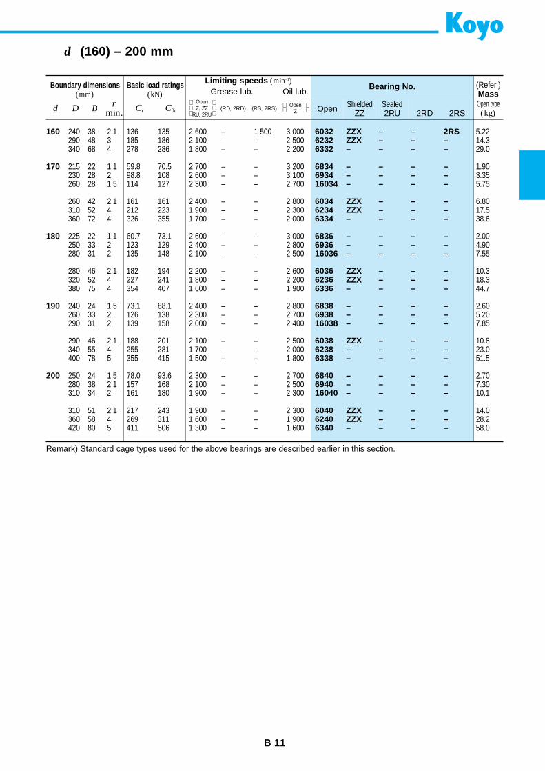
B 11
d (160) – 200 mm
Boundary dimensions(mm)
Basic load ratings(kN)
Limiting speeds (min–1)Grease lub. Oil lub.
Bearing No. (Refer.)Mass
d D Br
min. Cr C0r Open ShieldedZZ
Sealed2RU 2RD 2RS
Open type(kg)
Open Z, ZZ RU, 2RU
(RD, 2RD) (RS, 2RS) Open Z
160
170
180
190
200
6032 ZZX – – 2RS6232 ZZX – – –6332 – – – –
6834 – – – –6934 – – – –16034 – – – –
6034 ZZX – – –6234 ZZX – – –6334 – – – –
6836 – – – –6936 – – – –16036 – – – –
6036 ZZX – – –6236 ZZX – – –6336 – – – –
6838 – – – –6938 – – – –16038 – – – –
6038 ZZX – – –6238 – – – –6338 – – – –
6840 – – – –6940 – – – –16040 – – – –
6040 ZZX – – –6240 ZZX – – –6340 – – – –
240 38 2.1 136 135 2 600 – 1 500 3 000290 48 3 185 186 2 100 – – 2 500340 68 4 278 286 1 800 – – 2 200
215 22 1.1 59.8 70.5 2 700 – – 3 200230 28 2 98.8 108 2 600 – – 3 100260 28 1.5 114 127 2 300 – – 2 700
260 42 2.1 161 161 2 400 – – 2 800310 52 4 212 223 1 900 – – 2 300360 72 4 326 355 1 700 – – 2 000
225 22 1.1 60.7 73.1 2 600 – – 3 000250 33 2 123 129 2 400 – – 2 800280 31 2 135 148 2 100 – – 2 500
280 46 2.1 182 194 2 200 – – 2 600320 52 4 227 241 1 800 – – 2 200380 75 4 354 407 1 600 – – 1 900
240 24 1.5 73.1 88.1 2 400 – – 2 800260 33 2 126 138 2 300 – – 2 700290 31 2 139 158 2 000 – – 2 400
290 46 2.1 188 201 2 100 – – 2 500340 55 4 255 281 1 700 – – 2 000400 78 5 355 415 1 500 – – 1 800
250 24 1.5 78.0 93.6 2 300 – – 2 700280 38 2.1 157 168 2 100 – – 2 500310 34 2 161 180 1 900 – – 2 300
310 51 2.1 217 243 1 900 – – 2 300360 58 4 269 311 1 600 – – 1 900420 80 5 411 506 1 300 – – 1 600
5.2214.329.0
1.903.355.75
6.8017.538.6
2.004.907.55
10.318.344.7
2.605.207.85
10.823.051.5
2.707.3010.1
14.028.258.0
Remark) Standard cage types used for the above bearings are described earlier in this section.
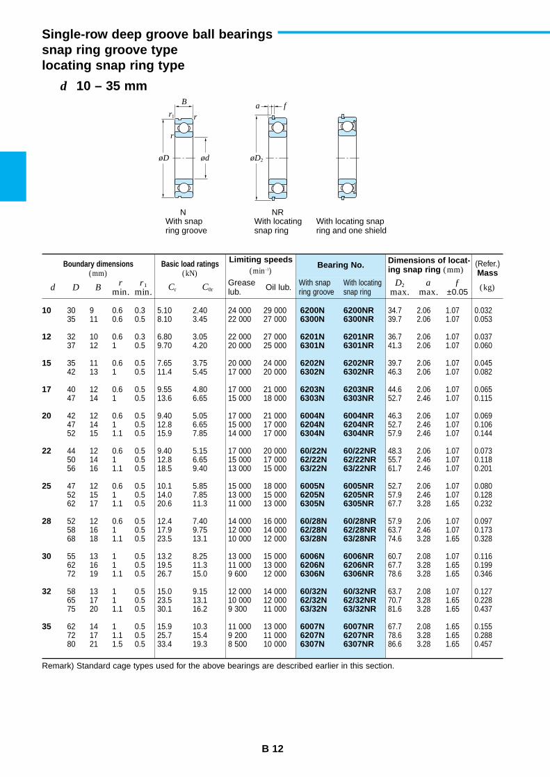
r
a f
r
r1
øD øD2ød
N NRWith snapring groove
With locatingsnap ring
With locating snapring and one shield
B
Single-row deep groove ball bearingssnap ring groove typelocating snap ring type
B 12
d 10 – 35 mm
Boundary dimensions(mm)
Basic load ratings(kN)
Limiting speeds(min–1)
Bearing No. Dimensions of locat-ing snap ring (mm)
(Refer.)Mass
d D Br
min.D2
max.a
max.ƒ
±0.05r1
min. Cr C0rWith snap ring groove
With locatingsnap ring (kg)Grease
lub. Oil lub.
10
12
15
17
20
22
25
28
30
32
35
6200N 6200NR6300N 6300NR
6201N 6201NR6301N 6301NR
6202N 6202NR6302N 6302NR
6203N 6203NR6303N 6303NR
6004N 6004NR6204N 6204NR6304N 6304NR
60/22N 60/22NR62/22N 62/22NR63/22N 63/22NR
6005N 6005NR6205N 6205NR6305N 6305NR
60/28N 60/28NR62/28N 62/28NR63/28N 63/28NR
6006N 6006NR6206N 6206NR6306N 6306NR
60/32N 60/32NR62/32N 62/32NR63/32N 63/32NR
6007N 6007NR6207N 6207NR6307N 6307NR
30 9 0.6 0.3 5.10 2.40 24 000 29 00035 11 0.6 0.5 8.10 3.45 22 000 27 000
32 10 0.6 0.3 6.80 3.05 22 000 27 00037 12 1 0.5 9.70 4.20 20 000 25 000
35 11 0.6 0.5 7.65 3.75 20 000 24 00042 13 1 0.5 11.4 5.45 17 000 20 000
40 12 0.6 0.5 9.55 4.80 17 000 21 00047 14 1 0.5 13.6 6.65 15 000 18 000
42 12 0.6 0.5 9.40 5.05 17 000 21 00047 14 1 0.5 12.8 6.65 15 000 17 00052 15 1.1 0.5 15.9 7.85 14 000 17 000
44 12 0.6 0.5 9.40 5.15 17 000 20 00050 14 1 0.5 12.8 6.65 15 000 17 00056 16 1.1 0.5 18.5 9.40 13 000 15 000
47 12 0.6 0.5 10.1 5.85 15 000 18 00052 15 1 0.5 14.0 7.85 13 000 15 00062 17 1.1 0.5 20.6 11.3 11 000 13 000
52 12 0.6 0.5 12.4 7.40 14 000 16 00058 16 1 0.5 17.9 9.75 12 000 14 00068 18 1.1 0.5 23.5 13.1 10 000 12 000
55 13 1 0.5 13.2 8.25 13 000 15 00062 16 1 0.5 19.5 11.3 11 000 13 00072 19 1.1 0.5 26.7 15.0 9 600 12 000
58 13 1 0.5 15.0 9.15 12 000 14 00065 17 1 0.5 23.5 13.1 10 000 12 00075 20 1.1 0.5 30.1 16.2 9 300 11 000
62 14 1 0.5 15.9 10.3 11 000 13 00072 17 1.1 0.5 25.7 15.4 9 200 11 00080 21 1.5 0.5 33.4 19.3 8 500 10 000
34.7 2.06 1.07 0.03239.7 2.06 1.07 0.053
36.7 2.06 1.07 0.03741.3 2.06 1.07 0.060
39.7 2.06 1.07 0.04546.3 2.06 1.07 0.082
44.6 2.06 1.07 0.06552.7 2.46 1.07 0.115
46.3 2.06 1.07 0.06952.7 2.46 1.07 0.10657.9 2.46 1.07 0.144
48.3 2.06 1.07 0.07355.7 2.46 1.07 0.11861.7 2.46 1.07 0.201
52.7 2.06 1.07 0.08057.9 2.46 1.07 0.12867.7 3.28 1.65 0.232
57.9 2.06 1.07 0.09763.7 2.46 1.07 0.17374.6 3.28 1.65 0.328
60.7 2.08 1.07 0.11667.7 3.28 1.65 0.19978.6 3.28 1.65 0.346
63.7 2.08 1.07 0.12770.7 3.28 1.65 0.22881.6 3.28 1.65 0.437
67.7 2.08 1.65 0.15578.6 3.28 1.65 0.28886.6 3.28 1.65 0.457
Remark) Standard cage types used for the above bearings are described earlier in this section.
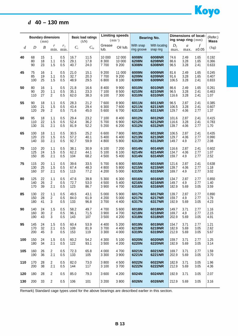
B 13
d 40 – 130 mm
Boundary dimensions(mm)
Basic load ratings(kN)
Limiting speeds(min–1)
Bearing No. Dimensions of locat-ing snap ring (mm)
(Refer.)Mass
d D Br
min.D2
max.a
max.ƒ
±0.05r1
min. Cr C0rWith snap ring groove
With locatingsnap ring (kg)Grease
lub. Oil lub.
40
45
50
55
60
65
70
75
80
85
90
95
100
105
110
120
130
6008N 6008NR6208N 6208NR6308N 6308NR
6009N 6009NR6209N 6209NR6309N 6309NR
6010N 6010NR6210N 6210NR6310N 6310NR
6011N 6011NR6211N 6211NR6311N 6311NR
6012N 6012NR6212N 6212NR6312N 6312NR
6013N 6013NR6213N 6213NR6313N 6313NR
6014N 6014NR6214N 6214NR6314N 6314NR
6015N 6015NR6215N 6215NR6315N 6315NR
6016N 6016NR6216N 6216NR6316N 6316NR
6017N 6017NR6217N 6217NR6317N 6317NR
6018N 6018NR6218N 6218NR6318N 6318NR
6019N 6019NR6219N 6219NR6319N 6319NR
6020N 6020NR6220N 6220NR
6021N 6021NR6221N 6221NR
6022N 6022NR6222N 6222NR
6024N 6024NR
6026N 6026NR
68 15 1 0.5 16.7 11.5 10 000 12 00080 18 1.1 0.5 29.1 17.8 8 300 10 00090 23 1.5 0.5 40.7 24.0 7 700 9 200
75 16 1 0.5 21.0 15.1 9 200 11 00085 19 1.1 0.5 32.7 20.3 7 700 9 200100 25 1.5 0.5 48.9 29.5 6 800 8 100
80 16 1 0.5 21.8 16.6 8 400 9 90090 20 1.1 0.5 35.1 23.3 7 100 8 500110 27 2 0.5 62.0 38.3 6 100 7 300
90 18 1.1 0.5 28.3 21.2 7 600 8 900100 21 1.5 0.5 43.4 29.4 6 300 7 600120 29 2 0.5 71.6 45.0 5 600 6 700
95 18 1.1 0.5 29.4 23.2 7 100 8 400110 22 1.5 0.5 52.4 36.2 5 700 6 900130 31 2.1 0.5 81.9 52.2 5 200 6 200
100 18 1.1 0.5 30.5 25.2 6 600 7 800120 23 1.5 0.5 57.2 40.1 5 400 6 400140 33 2.1 0.5 92.7 59.9 4 800 5 800
110 20 1.1 0.5 38.1 30.9 6 100 7 200125 24 1.5 0.5 62.2 44.1 5 100 6 100150 35 2.1 0.5 104 68.2 4 500 5 400
115 20 1.1 0.5 39.6 33.5 5 700 6 800130 25 1.5 0.5 67.4 48.3 4 800 5 800160 37 2.1 0.5 113 77.2 4 200 5 000
125 22 1.1 0.5 47.6 39.8 5 300 6 300140 26 2 0.5 72.7 53.0 4 500 5 400170 39 2.1 0.5 123 86.7 3 900 4 700
130 22 1.1 0.5 49.5 43.1 5 000 5 900150 28 2 0.5 84.0 61.9 4 200 5 000180 41 3 0.5 133 96.8 3 700 4 400
140 24 1.5 0.5 58.2 49.7 4 700 5 600160 30 2 0.5 96.1 71.5 3 900 4 700190 43 3 0.5 143 107 3 500 4 200
145 24 1.5 0.5 60.4 53.9 4 400 5 200170 32 2.1 0.5 109 81.9 3 700 4 400200 45 3 0.5 153 119 3 300 4 000
150 24 1.5 0.5 60.2 54.2 4 300 5 100180 34 2.1 0.5 122 93.1 3 500 4 200
160 26 2 0.5 72.3 65.8 4 000 4 700190 36 2.1 0.5 133 105 3 300 3 900
170 28 2 0.5 82.0 73.0 3 800 4 500200 38 2.1 0.5 144 117 3 100 3 700
180 28 2 0.5 85.0 79.3 3 600 4 200
200 33 2 0.5 106 101 3 200 3 800
74.6 2.49 1.65 0.19286.6 3.28 1.65 0.36696.5 3.28 2.41 0.633
81.6 2.49 1.65 0.24591.6 3.28 1.65 0.407106.5 3.28 2.41 0.833
86.6 2.49 1.65 0.26196.5 3.28 2.41 0.463116.6 3.28 2.41 1.07
96.5 2.87 2.41 0.385106.5 3.28 2.41 0.607129.7 4.06 2.77 1.37
101.6 2.87 2.41 0.415116.6 3.28 2.41 0.783139.7 4.06 2.77 1.70
106.5 2.87 2.41 0.435129.7 4.06 2.77 0.990149.7 4.9 2.77 2.08
116.6 2.87 2.41 0.602134.7 4.06 2.77 1.07159.7 4.9 2.77 2.52
121.6 2.87 2.41 0.638139.7 4.06 2.77 1.18169.7 4.9 2.77 3.02
134.7 2.87 2.77 0.850149.7 4.9 2.77 1.40182.9 5.69 3.05 3.59
139.7 2.87 2.77 0.890159.7 4.9 2.77 1.79192.9 5.69 3.05 4.23
149.7 3.71 2.77 1.16169.7 4.9 2.77 2.15202.9 5.69 3.05 4.91
154.7 3.71 2.77 1.21182.9 5.69 3.05 2.62212.9 5.69 3.05 5.67
159.7 3.71 2.77 1.25192.9 5.69 3.05 3.14
169.7 3.71 2.77 1.59202.9 5.69 3.05 3.70
182.9 3.71 3.05 1.96212.9 5.69 3.05 4.36
192.9 3.71 3.05 2.07
212.9 5.69 3.05 3.16
Remark) Standard cage types used for the above bearings are described earlier in this section.
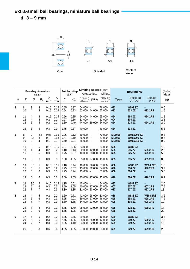
r
r
øD ød r1
r1
r1
r1
r1
r1
ZZ ZZL 2RS
Open Shielded Contactsealed
B
B1B1B1
Extra-small ball bearings, miniature ball bearings
B 14
d 3 – 9 mm
Boundary dimensions(mm)
Basic load ratings(kN)
Limiting speeds (min–1)Grease lub. Oil lub.
Bearing No. (Refer.)Mass
d D B B1r
min.r1
min. Cr C0r Open ShieldedZZ, ZZL
Sealed2RS (g) Open
ZZ, ZZL (2RS) Open Z, ZL
3
4
5
6
7
8
9
693 W693 ZZ –623 623 ZZ 623 2RS
694 694 ZZ 694 2RS604 604 ZZ –624 624 ZZ 624 2RS
634 634 ZZ –
ML5008 WML5008 ZZ –ML5009 WML5009 ZZ –ML5010 WML5010 ZZ –
685 W685 ZZ –695 695 ZZ 695 2RS625 625 ZZ 625 2RS
635 635 ZZ 635 2RS
686 W686 ZZ W686 2RS696 696 ZZ 696 2RS606 606 ZZ –
626 626 ZZ 626 2RS
687 W687 ZZ –607 607 ZZ 607 2RS627 627 ZZ 627 2RS
688 W688 ZZ W688 2RS698 698 ZZ 698 2RS608 608 ZZ 608 2RS
628 628 ZZ 628 2RS638 638 ZZ –
689 W689 ZZ –699 699 ZZ 699 2RS609 609 ZZ 609 2RS
629 629 ZZ 629 2RS
8 3 4 0.15 0.15 0.55 0.17 64 000 – 76 00010 4 4 0.15 0.15 0.64 0.23 52 000 44 000 63 000
11 4 4 0.15 0.15 0.96 0.35 54 000 44 000 65 00012 4 4 0.2 0.2 0.97 0.36 53 000 – 63 00013 5 5 0.2 0.2 1.30 0.49 44 000 39 000 54 000
16 5 5 0.3 0.3 1.75 0.67 40 000 – 49 000
8 2 2.5 0.08 0.05 0.26 0.12 59 000 – 70 0009 2.5 3 0.1 0.08 0.47 0.19 56 000 – 67 00010 3 4 0.1 0.1 0.50 0.21 55 000 – 65 000
11 3 5 0.15 0.15 0.97 0.36 53 000 – 63 00013 4 4 0.2 0.2 1.10 0.43 50 000 42 000 60 00016 5 5 0.3 0.3 1.75 0.67 40 000 33 000 49 000
19 6 6 0.3 0.3 2.60 1.05 35 000 27 000 43 000
13 3.5 5 0.15 0.15 1.10 0.44 48 000 36 000 57 00015 5 5 0.2 0.2 1.75 0.67 45 000 32 000 54 00017 6 6 0.3 0.3 1.95 0.74 43 000 – 51 000
19 6 6 0.3 0.3 2.60 1.05 35 000 27 000 43 000
14 3.5 5 0.15 0.15 1.15 0.51 45 000 – 54 00019 6 6 0.3 0.3 2.60 1.05 40 000 27 000 47 00022 7 7 0.3 0.3 3.30 1.35 31 000 23 000 37 000
16 4 5 0.2 0.2 1.60 0.71 42 000 28 000 50 00019 6 6 0.3 0.3 2.25 0.91 39 000 27 000 46 00022 7 7 0.3 0.3 3.30 1.35 34 000 23 000 41 000
24 8 8 0.3 0.3 3.35 1.40 28 000 22 000 35 00028 9 9 0.3 0.3 4.55 1.95 26 000 – 32 000
17 4 5 0.2 0.2 1.35 0.66 39 000 – 46 00020 6 6 0.3 0.3 2.45 1.05 35 000 25 000 42 00024 7 7 0.3 0.3 3.35 1.40 33 000 22 000 40 000
26 8 8 0.6 0.6 4.55 1.95 27 000 19 000 33 000
0.61.6
1.82.12.9
5.3
0.30.50.9
1.02.25.0
8.5
1.83.95.8
8.1
2.07.613
3.27.212
1829
3.57.515
20
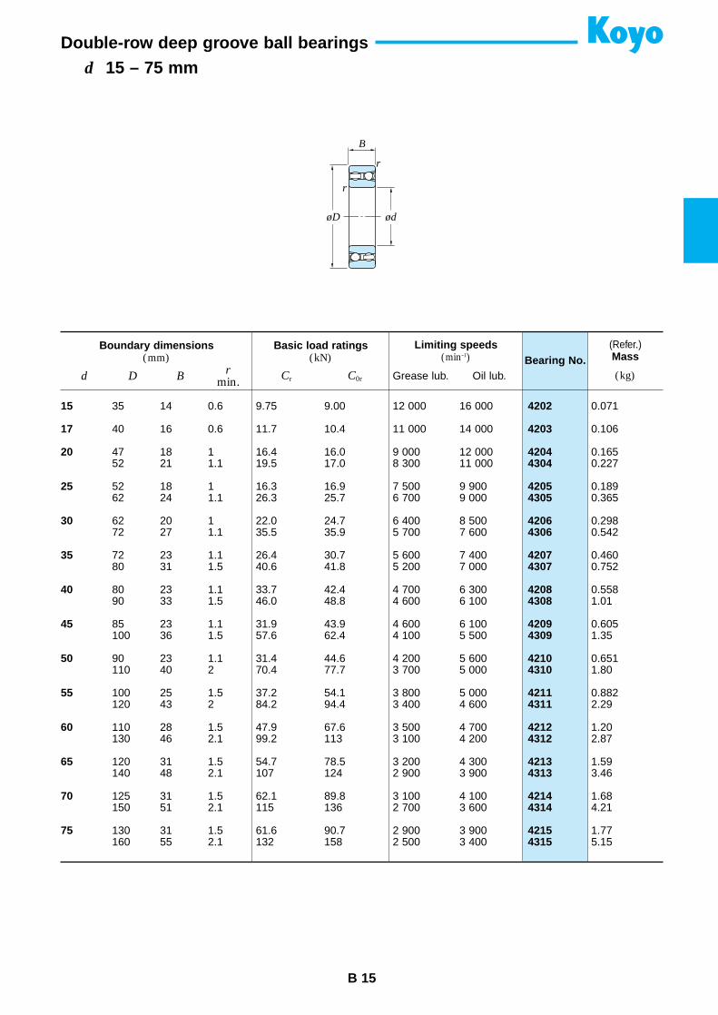
r
r
øD ød
B
B 15
d 15 – 75 mmDouble-row deep groove ball bearings
Boundary dimensions(mm)
Basic load ratings(kN)
Limiting speeds(min–1) Bearing No.
(Refer.)Mass
d D Br
min. Cr C0r (kg)Grease lub. Oil lub.
15
17
20
25
30
35
40
45
50
55
60
65
70
75
4202
4203
42044304
42054305
42064306
42074307
42084308
42094309
42104310
42114311
42124312
42134313
42144314
42154315
35 14 0.6 9.75 9.00 12 000 16 000
40 16 0.6 11.7 10.4 11 000 14 000
47 18 1 16.4 16.0 9 000 12 00052 21 1.1 19.5 17.0 8 300 11 000
52 18 1 16.3 16.9 7 500 9 90062 24 1.1 26.3 25.7 6 700 9 000
62 20 1 22.0 24.7 6 400 8 50072 27 1.1 35.5 35.9 5 700 7 600
72 23 1.1 26.4 30.7 5 600 7 40080 31 1.5 40.6 41.8 5 200 7 000
80 23 1.1 33.7 42.4 4 700 6 30090 33 1.5 46.0 48.8 4 600 6 100
85 23 1.1 31.9 43.9 4 600 6 100100 36 1.5 57.6 62.4 4 100 5 500
90 23 1.1 31.4 44.6 4 200 5 600110 40 2 70.4 77.7 3 700 5 000
100 25 1.5 37.2 54.1 3 800 5 000120 43 2 84.2 94.4 3 400 4 600
110 28 1.5 47.9 67.6 3 500 4 700130 46 2.1 99.2 113 3 100 4 200
120 31 1.5 54.7 78.5 3 200 4 300140 48 2.1 107 124 2 900 3 900
125 31 1.5 62.1 89.8 3 100 4 100150 51 2.1 115 136 2 700 3 600
130 31 1.5 61.6 90.7 2 900 3 900160 55 2.1 132 158 2 500 3 400
0.071
0.106
0.1650.227
0.1890.365
0.2980.542
0.4600.752
0.5581.01
0.6051.35
0.6511.80
0.8822.29
1.202.87
1.593.46
1.684.21
1.775.15
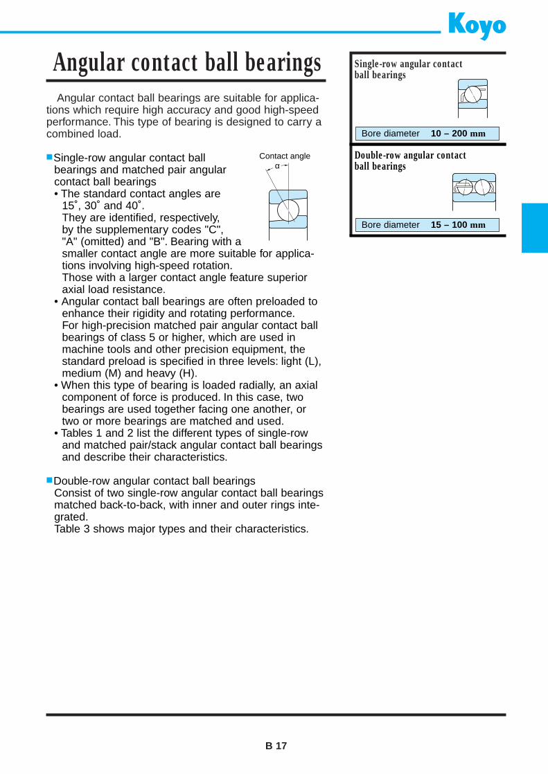
Angular contact ball bearings are suitable for applica-tions which require high accuracy and good high-speedperformance. This type of bearing is designed to carry acombined load.
Single-row angular contact ballbearings and matched pair angularcontact ball bearings• The standard contact angles are
15˚, 30˚ and 40˚.They are identified, respectively,by the supplementary codes "C","A" (omitted) and "B". Bearing with asmaller contact angle are more suitable for applica-tions involving high-speed rotation.Those with a larger contact angle feature superioraxial load resistance.
• Angular contact ball bearings are often preloaded toenhance their rigidity and rotating performance.For high-precision matched pair angular contact ballbearings of class 5 or higher, which are used inmachine tools and other precision equipment, thestandard preload is specified in three levels: light (L),medium (M) and heavy (H).
• When this type of bearing is loaded radially, an axialcomponent of force is produced. In this case, twobearings are used together facing one another, ortwo or more bearings are matched and used.
• Tables 1 and 2 list the different types of single-rowand matched pair/stack angular contact ball bearingsand describe their characteristics.
Double-row angular contact ball bearingsConsist of two single-row angular contact ball bearingsmatched back-to-back, with inner and outer rings inte-grated.Table 3 shows major types and their characteristics.
B 17
Angular contact ball bearings Single-row angular contact ball bearings
Bore diameter 10 – 200 mm
Double-row angular contact ball bearings
Bore diameter 15 – 100 mm
αContact angle
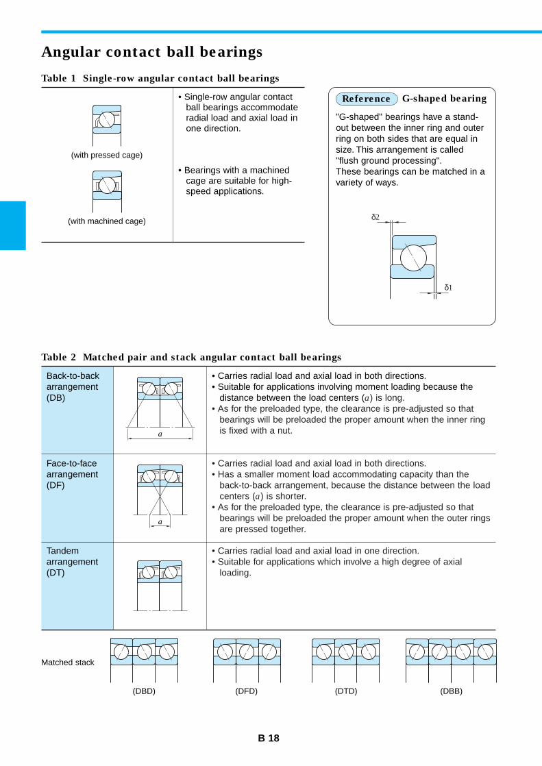
(DBD) (DFD) (DTD) (DBB)
Back-to-backarrangement(DB)
Face-to-facearrangement(DF)
Tandemarrangement(DT)
• Carries radial load and axial load in both directions.• Suitable for applications involving moment loading because the
distance between the load centers (a) is long.• As for the preloaded type, the clearance is pre-adjusted so that
bearings will be preloaded the proper amount when the inner ring is fixed with a nut.
• Carries radial load and axial load in both directions.• Has a smaller moment load accommodating capacity than the
back-to-back arrangement, because the distance between the loadcenters (a) is shorter.
• As for the preloaded type, the clearance is pre-adjusted so thatbearings will be preloaded the proper amount when the outer ringsare pressed together.
• Carries radial load and axial load in one direction.• Suitable for applications which involve a high degree of axial
loading.
B 18
Angular contact ball bearings
Table 1 Single-row angular contact ball bearings
• Single-row angular contactball bearings accommodateradial load and axial load inone direction.
• Bearings with a machinedcage are suitable for high-speed applications.
"G-shaped" bearings have a stand-out between the inner ring and outerring on both sides that are equal insize. This arrangement is called"flush ground processing".These bearings can be matched in avariety of ways.
Reference G-shaped bearing
Table 2 Matched pair and stack angular contact ball bearings
Matched stack
(with pressed cage)
(with machined cage) δ2
δ1
a
a
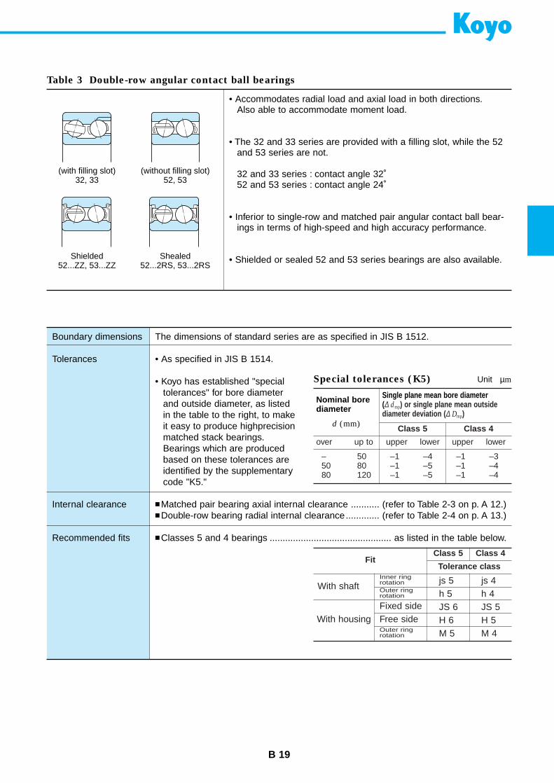
(with filling slot)32, 33
(without filling slot)52, 53
Shielded52...ZZ, 53...ZZ
Shealed52...2RS, 53...2RS
The dimensions of standard series are as specified in JIS B 1512.
• As specified in JIS B 1514.
• Koyo has established "specialtolerances" for bore diameterand outside diameter, as listedin the table to the right, to makeit easy to produce highprecisionmatched stack bearings.Bearings which are producedbased on these tolerances areidentified by the supplementarycode "K5."
Matched pair bearing axial internal clearance ........... (refer to Table 2-3 on p. A 12.) Double-row bearing radial internal clearance............. (refer to Table 2-4 on p. A 13.)
Classes 5 and 4 bearings ............................................... as listed in the table below.
B 19
Table 3 Double-row angular contact ball bearings
• Accommodates radial load and axial load in both directions.Also able to accommodate moment load.
• The 32 and 33 series are provided with a filling slot, while the 52and 53 series are not.
32 and 33 series : contact angle 32˚52 and 53 series : contact angle 24˚
• Inferior to single-row and matched pair angular contact ball bear-ings in terms of high-speed and high accuracy performance.
• Shielded or sealed 52 and 53 series bearings are also available.
Boundary dimensions
Tolerances
Internal clearance
Recommended fits
Special tolerances (K5) Unit µm
Nominal bore diameter
d (mm)
Single plane mean bore diameter (∆ dmp) or single plane mean outsidediameter deviation ( ∆ Dmp)
Class 5 Class 4
over up to upper lower upper lower
– 50 –1 –4 –1 –350 80 –1 –5 –1 –480 120 –1 –5 –1 –4
FitClass 5 Class 4
Tolerance class
With shaft
With housing
Inner ring rotation js 5
h 5JS 6H 6M 5
js 4h 4JS 5H 5M 4
Outer ringrotation
Fixed sideFree sideOuter ringrotation
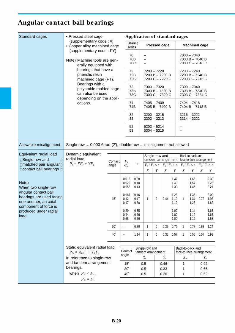
Standard cages
Allowable misalignment
Equivalent radial loadSingle-row andmatched pair angularcontact ball bearings
Note)When two single-rowangular contact ballbearings are used facingone another, an axialcomponent of force isproduced under radialload.
• Pressed steel cage(supplementary code : //)
• Copper alloy machined cage(supplementary code : FY)
Note) Machine tools are gen-erally equipped withbearings that have aphenolic resinmachined cage (FT).Bearings with apolyamide molded cagecan also be useddepending on the appli-cations.
Single-row ... 0.000 6 rad (2'), double-row ... misalignment not allowed
Dynamic equivalentradial load
Pr = XFr + YFa
B 20
Angular contact ball bearings
Fa
C0re
Single-row and tandem arrangement
Back-to-back and face-to-face arrangement
Fa / Fr ≤ e Fa / Fr > e Fa / Fr ≤ e Fa / Fr > e
X Y X Y X Y X Y
0.015 0.38 1.47 1.65 2.390.029 0.40 1.40 1.57 2.280.058 0.43 1.30 1.46 2.21
0.087 0.46 1.23 1.38 2.0015˚ 0.12 0.47 1 0 0.44 1.19 1 1.34 0.72 1.93
0.17 0.50 1.12 1.26 1.82
0.29 0.55 1.02 1.14 1.660.44 0.56 1.00 1.12 1.630.58 0.56 1.00 1.12 1.63
30˚ – 0.80 1 0 0.39 0.76 1 0.78 0.63 1.24
40˚ – 1.14 1 0 0.35 0.57 1 0.55 0.57 0.93
Static equivalent radial loadP0r = X0 Fr + Y0 Fa
In reference to single-rowand tandem arrangementbearings,
when P0r < Fr ,
P0r = Fr
Application of standard cages
Bearingseries Pressed cage Machined cage
70 – 7000 – 704070B – 7000 B – 7040 B70C – 7000 C – 7040 C
72 7200 – 7220 7200 – 724072B 7200 B – 7220 B 7200 B – 7240 B72C 7200 C – 7220 C 7200 C – 7240 C
73 7300 – 7320 7300 – 734073B 7303 B – 7320 B 7303 B – 7340 B73C 7303 C – 7320 C 7303 C – 7334 C
74 7405 – 7409 7404 – 741874B 7405 B – 7409 B 7404 B – 7418 B
32 3200 – 3215 3216 – 322233 3302 – 3313 3314 – 3322
52 5203 – 5214 –53 5304 – 5315 –
Contactangle
Contactangle
Single-row andtandem arrangement
Back-to-back and face-to-face arrangement
X0 Y0 X0 Y0
15˚ 0.5 0.46 1 0.9230˚ 0.5 0.33 1 0.6640˚ 0.5 0.26 1 0.52
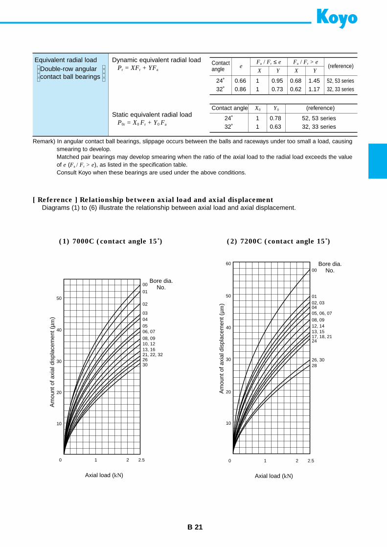
B 21
Equivalent radial loadDouble-row angularcontact ball bearings
Dynamic equivalent radial loadPr = XFr + YFa
Static equivalent radial loadP0r = X0 Fr + Y0 Fa
eFa / Fr ≤ e Fa / Fr > e
X Y X Y
24˚ 0.66 1 0.95 0.68 1.45 52, 53 series32˚ 0.86 1 0.73 0.62 1.17 32, 33 series
Contactangle (reference)
Contact angle X0 Y0 (reference)
24˚ 1 0.78 52, 53 series32˚ 1 0.63 32, 33 series
Remark) In angular contact ball bearings, slippage occurs between the balls and raceways under too small a load, causingsmearing to develop.Matched pair bearings may develop smearing when the ratio of the axial load to the radial load exceeds the valueof e (Fa / Fr > e), as listed in the specification table.Consult Koyo when these bearings are used under the above conditions.
[ Reference ] Relationship between axial load and axial displacement
Diagrams (1) to (6) illustrate the relationship between axial load and axial displacement.
(1) 7000C (contact angle 15˚) (2) 7200C (contact angle 15˚)
00
50
40
30
20
10
0 1 2 2.5
01
02
03040506, 07
08, 0910, 1213, 1621, 22, 322630
Bore dia.No.
Axial load (kN)
Am
ount
of a
xial
dis
plac
emen
t (µm
)
50
60
40
30
20
10
0 1 2 2.5
00
01
0405, 06, 07
02, 03
08, 0912, 14
26, 30
13, 1517, 18, 2124
28
Bore dia.No.
Axial load (kN)
Am
ount
of a
xial
dis
plac
emen
t (µm
)
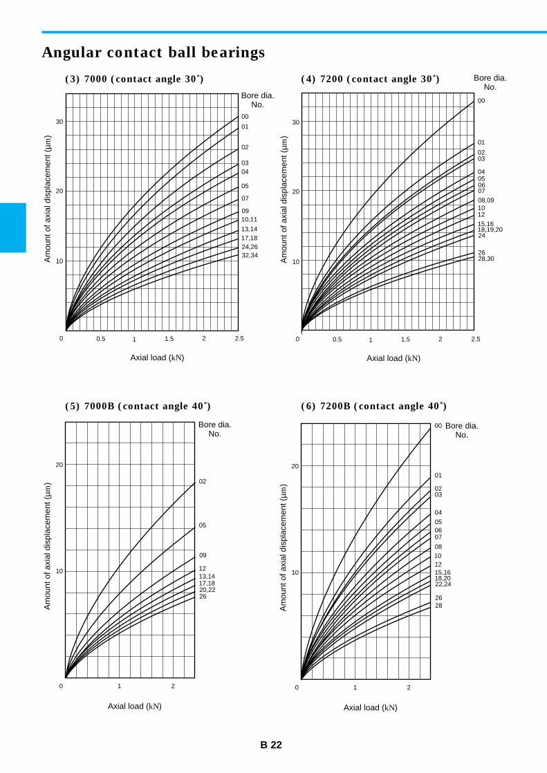
B 22
Angular contact ball bearings
(3) 7000 (contact angle 30˚) (4) 7200 (contact angle 30˚)
(5) 7000B (contact angle 40˚) (6) 7200B (contact angle 40˚)
0030
20
10
0 10.5 1.5 2 2.5
01
02
0304
05
07
0910,11
13,1417,1824,2632,34
Bore dia.No.
Axial load (kN)
Am
ount
of a
xial
dis
plac
emen
t (µm
)
00
30
20
10
01
0203
04050607
08,091012
15,1618,19,2024
28,3026
Bore dia.No.
Am
ount
of a
xial
dis
plac
emen
t (µm
)
0 10.5 1.5 2 2.5
Axial load (kN)
20
10
0 1 2
02
05
09
1213,1417,1820,2226
Bore dia.No.
Axial load (kN)
Am
ount
of a
xial
dis
plac
emen
t (µm
)
20
10
0 1 2
01
00
050607
08
04
0302
101215,1618,2022,24
2628
Bore dia.No.
Axial load (kN)
Am
ount
of a
xial
dis
plac
emen
t (µm
)

B 23
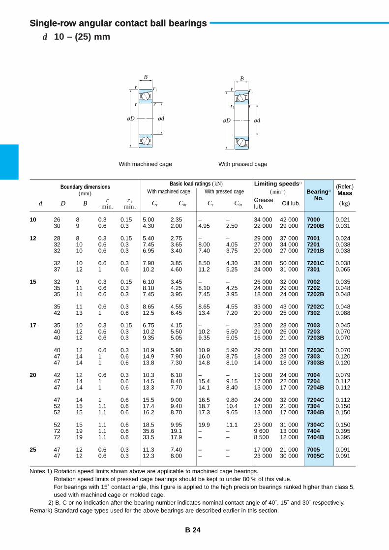
rr
r
øD ød
r1
r
r
øD ød
r1
r1
With machined cage With pressed cage
B B
Single-row angular contact ball bearings
B 24
d 10 – (25) mmSingle-row angular contact ball bearings
Boundary dimensions(mm)
Basic load ratings (kN)With machined cage With pressed cage
Limiting speeds 1)
(min–1) Bearing 2)
No.
(Refer.)Mass
d D Br
min.r1
min. Cr C0rCr C0r (kg)Greaselub. Oil lub.
10
12
15
17
20
25
70007200B
700172017201B
7201C7301
700272027202B
7202C7302
700372037203B
7203C73037303B
700472047204B
7204C73047304B
7304C74047404B
70057005C
26 8 0.3 0.15 5.00 2.35 – – 34 000 42 00030 9 0.6 0.3 4.30 2.00 4.95 2.50 22 000 29 000
28 8 0.3 0.15 5.40 2.75 – – 29 000 37 00032 10 0.6 0.3 7.45 3.65 8.00 4.05 27 000 34 00032 10 0.6 0.3 6.95 3.40 7.40 3.75 20 000 27 000
32 10 0.6 0.3 7.90 3.85 8.50 4.30 38 000 50 00037 12 1 0.6 10.2 4.60 11.2 5.25 24 000 31 000
32 9 0.3 0.15 6.10 3.45 – – 26 000 32 00035 11 0.6 0.3 8.10 4.25 8.10 4.25 24 000 29 00035 11 0.6 0.3 7.45 3.95 7.45 3.95 18 000 24 000
35 11 0.6 0.3 8.65 4.55 8.65 4.55 33 000 43 00042 13 1 0.6 12.5 6.45 13.4 7.20 20 000 25 000
35 10 0.3 0.15 6.75 4.15 – – 23 000 28 00040 12 0.6 0.3 10.2 5.50 10.2 5.50 21 000 26 00040 12 0.6 0.3 9.35 5.05 9.35 5.05 16 000 21 000
40 12 0.6 0.3 10.9 5.90 10.9 5.90 29 000 38 00047 14 1 0.6 14.9 7.90 16.0 8.75 18 000 23 00047 14 1 0.6 13.8 7.30 14.8 8.10 14 000 18 000
42 12 0.6 0.3 10.3 6.10 – – 19 000 24 00047 14 1 0.6 14.5 8.40 15.4 9.15 17 000 22 00047 14 1 0.6 13.3 7.70 14.1 8.40 13 000 17 000
47 14 1 0.6 15.5 9.00 16.5 9.80 24 000 32 00052 15 1.1 0.6 17.4 9.40 18.7 10.4 17 000 21 00052 15 1.1 0.6 16.2 8.70 17.3 9.65 13 000 17 000
52 15 1.1 0.6 18.5 9.95 19.9 11.1 23 000 31 00072 19 1.1 0.6 35.6 19.1 – – 9 600 13 00072 19 1.1 0.6 33.5 17.9 – – 8 500 12 000
47 12 0.6 0.3 11.3 7.40 – – 17 000 21 00047 12 0.6 0.3 12.3 8.00 – – 23 000 30 000
0.0210.031
0.0240.0380.038
0.0380.065
0.0350.0480.048
0.0480.088
0.0450.0700.070
0.0700.1200.120
0.0790.1120.112
0.1120.1500.150
0.1500.3950.395
0.0910.091
Notes 1) Rotation speed limits shown above are applicable to machined cage bearings.Rotation speed limits of pressed cage bearings should be kept to under 80 % of this value.For bearings with 15˚ contact angle, this figure is applied to the high precision bearings ranked higher than class 5,used with machined cage or molded cage.
2) B, C or no indication after the bearing number indicates nominal contact angle of 40˚, 15˚ and 30˚ respectively.Remark) Standard cage types used for the above bearings are described earlier in this section.
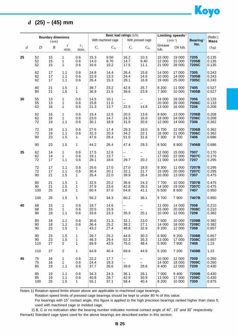
B 25
d (25) – (45) mm
Boundary dimensions(mm)
Limiting speeds 1)
(min–1) Bearing 2)
No.
(Refer.)Mass
d D Br
min.r1
min. Cr C0rCr C0r (kg)Greaselub. Oil lub.
25
30
35
40
45
72057205B7205C
73057305B7305C
74057405B
70067006C7206
7206B7206C7306
7306B7306C7406
7406B
70077007C7207
7207B7207C7307
7307B7307C7407
7407B
70087008C7208
7208B7208C7308
7308B7308C7408
7408B
70097009C7209
7209B7209C7309
52 15 1 0.6 15.3 9.50 16.2 10.3 15 000 19 00052 15 1 0.6 14.0 8.70 14.7 9.40 12 000 15 00052 15 1 0.6 16.6 10.2 17.5 11.1 21 000 28 000
62 17 1.1 0.6 24.8 14.4 26.4 15.8 14 000 17 00062 17 1.1 0.6 22.9 13.3 24.4 14.6 10 000 14 00062 17 1.1 0.6 26.4 15.3 28.1 16.8 19 000 25 000
80 21 1.5 1 39.7 23.2 42.6 25.7 8 200 11 00080 21 1.5 1 36.9 21.5 39.6 23.9 7 300 10 000
55 13 1 0.6 14.5 10.1 – – 14 000 18 00055 13 1 0.6 15.8 11.0 – – 20 000 26 00062 16 1 0.6 21.3 13.7 22.5 14.8 13 000 16 000
62 16 1 0.6 19.4 12.5 20.5 13.6 9 600 13 00062 16 1 0.6 23.0 14.7 24.3 16.0 18 000 24 00072 19 1.1 0.6 30.1 18.9 31.9 20.6 12 000 14 000
72 19 1.1 0.6 27.6 17.4 29.3 19.0 8 700 12 00072 19 1.1 0.6 32.3 20.3 34.2 22.1 16 000 21 00090 23 1.5 1 47.6 28.4 51.0 31.6 7 300 9 700
90 23 1.5 1 44.2 26.4 47.4 29.3 6 500 8 900
62 14 1 0.6 17.5 12.6 – – 12 000 15 00062 14 1 0.6 19.1 13.7 – – 17 000 22 00072 17 1.1 0.6 28.1 18.6 29.7 20.2 11 000 14 000
72 17 1.1 0.6 25.6 17.0 27.0 18.5 8 300 11 00072 17 1.1 0.6 30.4 20.1 32.1 21.7 15 000 20 00080 21 1.5 1 35.4 22.0 39.9 26.4 10 000 13 000
80 21 1.5 1 32.5 20.2 36.6 24.3 7 700 10 00080 21 1.5 1 37.9 23.6 42.8 28.3 14 000 19 000100 25 1.5 1 60.4 37.0 64.8 41.1 6 500 8 600
100 25 1.5 1 56.2 34.3 60.2 38.1 5 700 7 900
68 15 1 0.6 18.7 14.6 – – 11 000 14 00068 15 1 0.6 20.5 15.9 – – 15 000 20 00080 18 1.1 0.6 33.6 23.3 35.3 25.1 10 000 12 000
80 18 1.1 0.6 30.6 21.3 32.1 23.0 7 500 10 00080 18 1.1 0.6 36.4 25.2 38.2 27.1 14 000 18 00090 23 1.5 1 43.2 27.4 48.8 32.9 9 200 12 000
90 23 1.5 1 39.7 25.2 44.8 30.3 6 900 9 20090 23 1.5 1 46.3 29.4 52.3 35.3 13 000 17 000110 27 2 1 69.9 43.5 75.0 48.4 5 900 7 900
110 27 2 1 64.9 40.4 69.6 44.9 5 200 7 200
75 16 1 0.6 22.2 17.7 – – 10 000 12 00075 16 1 0.6 24.4 19.3 – – 14 000 18 00085 19 1.1 0.6 37.7 26.6 39.6 28.6 9 400 12 000
85 19 1.1 0.6 34.3 24.3 36.1 26.1 7 000 9 40085 19 1.1 0.6 40.8 28.7 42.9 30.9 13 000 17 000100 25 1.5 1 55.1 37.1 58.4 40.4 8 200 10 000
0.1350.1350.135
0.2430.2430.243
0.5270.527
0.1330.1330.208
0.2080.2080.362
0.3620.3620.686
0.686
0.1700.1700.295
0.2950.2950.475
0.4750.4750.950
0.950
0.2100.2100.382
0.3820.3820.657
0.6570.6571.23
1.23
0.2600.2600.430
0.4300.4300.875
Notes 1) Rotation speed limits shown above are applicable to machined cage bearings.Rotation speed limits of pressed cage bearings should be kept to under 80 % of this value.For bearings with 15˚ contact angle, this figure is applied to the high precision bearings ranked higher than class 5,used with machined cage or molded cage.
2) B, C or no indication after the bearing number indicates nominal contact angle of 40˚, 15˚ and 30˚ respectively.Remark) Standard cage types used for the above bearings are described earlier in this section.
Basic load ratings (kN)With machined cage With pressed cage

Basic load ratings (kN)With machined cage With pressed cage
B 26
d (45) – (60) mmSingle-row angular contact ball bearings
Boundary dimensions(mm)
Limiting speeds 1)
(min–1) Bearing 2)
No.
(Refer.)Mass
d D Br
min.r1
min.Cr C0rCr C0r (kg)Grease
lub. Oil lub.
45
50
55
60
7309B7309C7409
7409B
70107010C7210
7210B7210C7310
7310B7310C7410
7410B
70117011C7211
7211B7211C7311
7311B74117411B
70127012C7212
7212B7212C7312
100 25 1.5 1 50.6 34.1 53.6 37.2 6 200 8 200100 25 1.5 1 59.2 39.7 62.7 43.4 11 000 15 000120 29 2 1 84.9 53.8 91.1 59.8 5 400 7 100
120 29 2 1 78.9 50.0 84.7 55.5 4 800 6 600
80 16 1 0.6 23.6 20.1 – – 9 200 11 00080 16 1 0.6 26.0 21.9 – – 13 000 17 00090 20 1.1 0.6 39.4 29.4 41.3 31.5 8 500 11 000
90 20 1.1 0.6 35.7 26.7 37.4 28.6 6 400 8 50090 20 1.1 0.6 42.8 31.8 44.8 34.1 12 000 16 000110 27 2 1 70.1 48.1 74.3 52.5 7 300 9 100
110 27 2 1 64.4 44.3 68.2 48.3 5 500 7 300110 27 2 1 75.1 51.6 79.6 56.2 10 000 13 000130 31 2.1 1.1 97.4 65.3 – – 4 900 6 600
130 31 2.1 1.1 90.2 60.4 – – 4 400 6 000
90 18 1.1 0.6 31.1 26.3 – – 8 300 10 00090 18 1.1 0.6 34.1 28.6 – – 11 000 15 000100 21 1.5 1 48.7 37.1 51.0 39.8 7 600 9 500
100 21 1.5 1 44.1 33.8 46.2 36.2 5 700 7 600100 21 1.5 1 52.9 40.2 55.4 43.1 11 000 14 000120 29 2 1 80.9 56.5 85.8 61.7 6 700 8 400
120 29 2 1 74.3 52.0 78.7 56.7 5 000 6 700140 33 2.1 1.1 118 82.4 – – 4 500 6 000140 33 2.1 1.1 110 76.5 – – 4 000 5 500
95 18 1.1 0.6 31.9 28.1 – – 7 700 9 70095 18 1.1 0.6 35.0 30.6 – – 11 000 14 000110 22 1.5 1 58.9 45.7 61.7 49.0 6 900 8 600
110 22 1.5 1 53.4 41.6 55.9 44.6 5 100 6 900110 22 1.5 1 64.0 49.5 67.0 53.0 9 500 13 000130 31 2.1 1.1 92.5 65.6 98.1 71.6 6 200 7 700
0.8750.8751.55
1.55
0.2900.2900.485
0.4850.4851.14
1.141.141.92
1.92
0.4200.4200.635
0.6350.6351.45
1.452.362.36
0.4500.4500.820
0.8200.8201.81
Notes 1) Rotation speed limits shown above are applicable to machined cage bearings.Rotation speed limits of pressed cage bearings should be kept to under 80 % of this value.For bearings with 15˚ contact angle, this figure is applied to the high precision bearings ranked higher than class 5,used with machined cage or molded cage.
2) B, C or no indication after the bearing number indicates nominal contact angle of 40˚, 15˚ and 30˚ respectively.Remark) Standard cage types used for the above bearings are described earlier in this section.
rr
r
øD ød
r1
r
r
øD ød
r1
r1
With machined cage With pressed cage
B B
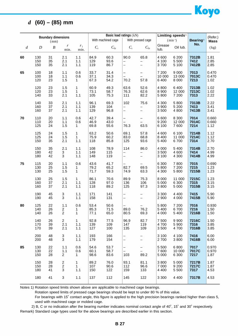
Basic load ratings (kN)With machined cage With pressed cage
B 27
d (60) – (85) mm
Boundary dimensions(mm)
Limiting speeds 1)
(min–1) Bearing 2)
No.
(Refer.)Mass
d D Br
min.r1
min.Cr C0rCr C0r (kg)Grease
lub. Oil lub.
60
65
70
75
80
85
7312B74127412B
70137013C7213
7213B7213C7313
7313B74137413B
70147014C7214
7214B7214C7314
7314B74147414B
701572157215B
7215C73157315B
74157415B
701672167216B
7216C73167316B
74167416B
70177017C7217
7217B7217C7317
7317B
130 31 2.1 1.1 84.9 60.3 90.0 65.8 4 600 6 200150 35 2.1 1.1 129 93.6 – – 4 100 5 500150 35 2.1 1.1 119 86.7 – – 3 700 5 100
100 18 1.1 0.6 33.7 31.4 – – 7 200 9 000100 18 1.1 0.6 37.1 34.3 – – 10 000 13 000120 23 1.5 1 67.3 54.2 70.2 57.8 6 400 8 000
120 23 1.5 1 60.9 49.3 63.6 52.6 4 800 6 400120 23 1.5 1 73.1 58.7 76.3 62.6 8 900 12 000140 33 2.1 1.1 105 75.3 111 82.2 5 800 7 200
140 33 2.1 1.1 96.1 69.3 102 75.6 4 300 5 800160 37 2.1 1.1 139 104 – – 3 900 5 200160 37 2.1 1.1 129 96.8 – – 3 500 4 800
110 20 1.1 0.6 42.7 39.4 – – 6 600 8 300110 20 1.1 0.6 46.9 43.0 – – 9 200 12 000125 24 1.5 1 69.8 55.6 76.3 63.5 6 100 7 600
125 24 1.5 1 63.2 50.6 69.1 57.8 4 600 6 100125 24 1.5 1 75.9 60.2 83.0 68.8 8 400 11 000150 35 2.1 1.1 118 85.8 125 93.6 5 400 6 700
150 35 2.1 1.1 108 78.9 114 86.0 4 000 5 400180 42 3 1.1 149 115 – – 3 500 4 600180 42 3 1.1 148 119 – – 3 100 4 300
115 20 1.1 0.6 43.6 41.7 – – 6 300 7 800130 25 1.5 1 79.2 65.2 82.7 69.5 5 800 7 200130 25 1.5 1 71.7 59.3 74.9 63.3 4 300 5 800
130 25 1.5 1 86.1 70.6 89.9 75.3 8 000 11 000160 37 2.1 1.1 128 97.0 136 106 5 000 6 300160 37 2.1 1.1 118 89.2 125 97.3 3 800 5 000
190 45 3 1.1 171 141 – – 3 300 4 400190 45 3 1.1 158 131 – – 2 900 4 000
125 22 1.1 0.6 53.4 50.6 – – 5 800 7 200140 26 2 1 85.3 71.5 89.0 76.2 5 400 6 700140 26 2 1 77.1 65.0 80.5 69.3 4 000 5 400
140 26 2 1 92.8 77.5 96.9 82.7 7 500 9 900170 39 2.1 1.1 139 109 147 119 4 700 5 900170 39 2.1 1.1 127 100 135 109 3 500 4 700
200 48 3 1.1 193 166 – – 3 100 4 100200 48 3 1.1 179 154 – – 2 700 3 800
130 22 1.1 0.6 54.6 53.7 – – 5 500 6 800130 22 1.1 0.6 60.1 58.7 – – 7 600 10 000150 28 2 1 98.6 83.6 103 89.2 5 000 6 300
150 28 2 1 89.2 76.0 93.1 81.1 3 800 5 000150 28 2 1 107 90.6 112 96.6 7 000 9 200180 41 3 1.1 150 122 159 133 4 400 5 500
180 41 3 1.1 137 112 145 122 3 300 4 400
1.812.852.85
0.4700.4701.02
1.021.022.22
2.223.413.41
0.6600.6601.12
1.121.122.70
2.704.994.99
0.6901.231.23
1.233.153.15
5.905.90
0.9301.501.50
1.503.853.85
6.006.00
0.9700.9701.87
1.871.874.53
4.53
Notes 1) Rotation speed limits shown above are applicable to machined cage bearings.Rotation speed limits of pressed cage bearings should be kept to under 80 % of this value.For bearings with 15˚ contact angle, this figure is applied to the high precision bearings ranked higher than class 5,used with machined cage or molded cage.
2) B, C or no indication after the bearing number indicates nominal contact angle of 40˚, 15˚ and 30˚ respectively.Remark) Standard cage types used for the above bearings are described earlier in this section.
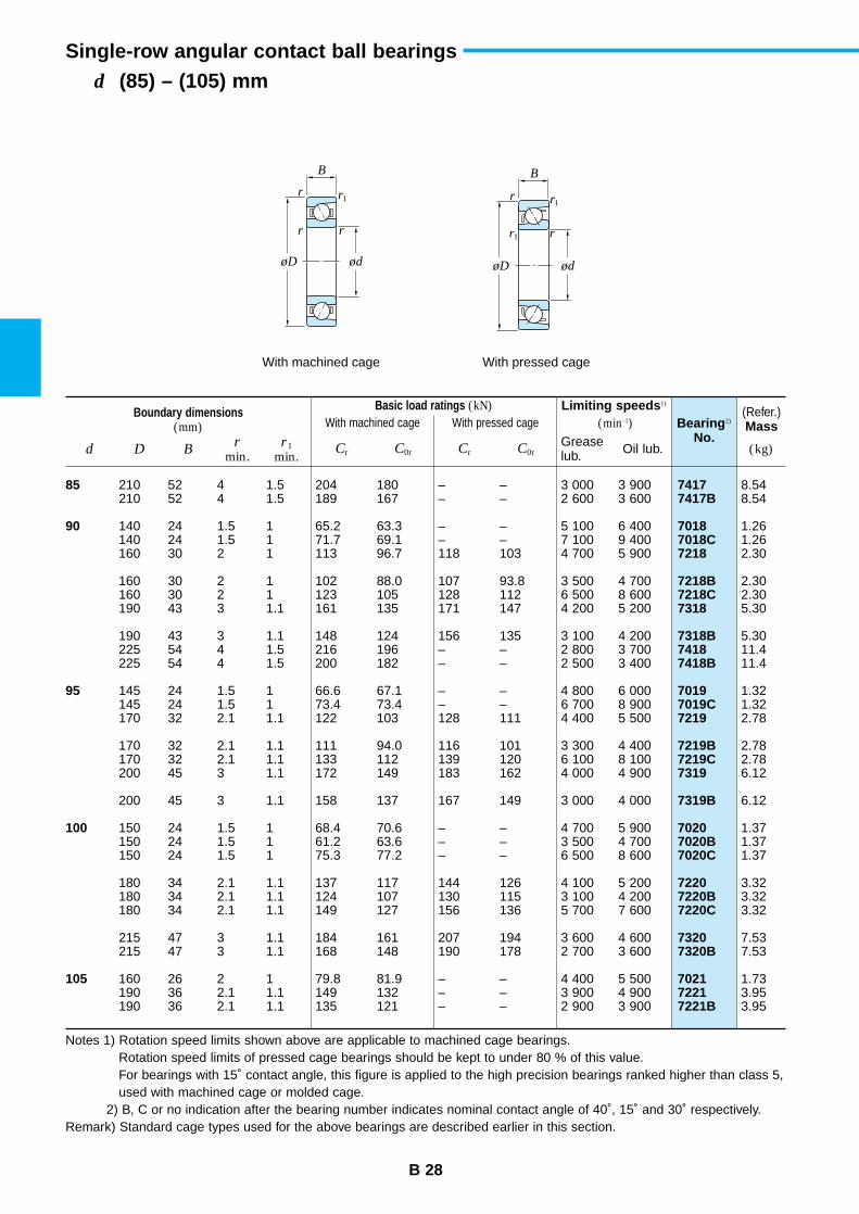
B 28
d (85) – (105) mmSingle-row angular contact ball bearings
Boundary dimensions(mm)
Limiting speeds 1)
(min–1) Bearing 2)
No.
(Refer.)Mass
d D Br
min.r1
min.Cr C0rCr C0r (kg)Grease
lub. Oil lub.
85
90
95
100
105
74177417B
70187018C7218
7218B7218C7318
7318B74187418B
70197019C7219
7219B7219C7319
7319B
70207020B7020C
72207220B7220C
73207320B
702172217221B
210 52 4 1.5 204 180 – – 3 000 3 900210 52 4 1.5 189 167 – – 2 600 3 600
140 24 1.5 1 65.2 63.3 – – 5 100 6 400140 24 1.5 1 71.7 69.1 – – 7 100 9 400160 30 2 1 113 96.7 118 103 4 700 5 900
160 30 2 1 102 88.0 107 93.8 3 500 4 700160 30 2 1 123 105 128 112 6 500 8 600190 43 3 1.1 161 135 171 147 4 200 5 200
190 43 3 1.1 148 124 156 135 3 100 4 200225 54 4 1.5 216 196 – – 2 800 3 700225 54 4 1.5 200 182 – – 2 500 3 400
145 24 1.5 1 66.6 67.1 – – 4 800 6 000145 24 1.5 1 73.4 73.4 – – 6 700 8 900170 32 2.1 1.1 122 103 128 111 4 400 5 500
170 32 2.1 1.1 111 94.0 116 101 3 300 4 400170 32 2.1 1.1 133 112 139 120 6 100 8 100200 45 3 1.1 172 149 183 162 4 000 4 900
200 45 3 1.1 158 137 167 149 3 000 4 000
150 24 1.5 1 68.4 70.6 – – 4 700 5 900150 24 1.5 1 61.2 63.6 – – 3 500 4 700150 24 1.5 1 75.3 77.2 – – 6 500 8 600
180 34 2.1 1.1 137 117 144 126 4 100 5 200180 34 2.1 1.1 124 107 130 115 3 100 4 200180 34 2.1 1.1 149 127 156 136 5 700 7 600
215 47 3 1.1 184 161 207 194 3 600 4 600215 47 3 1.1 168 148 190 178 2 700 3 600
160 26 2 1 79.8 81.9 – – 4 400 5 500190 36 2.1 1.1 149 132 – – 3 900 4 900190 36 2.1 1.1 135 121 – – 2 900 3 900
8.548.54
1.261.262.30
2.302.305.30
5.3011.411.4
1.321.322.78
2.782.786.12
6.12
1.371.371.37
3.323.323.32
7.537.53
1.733.953.95
Notes 1) Rotation speed limits shown above are applicable to machined cage bearings.Rotation speed limits of pressed cage bearings should be kept to under 80 % of this value.For bearings with 15˚ contact angle, this figure is applied to the high precision bearings ranked higher than class 5,used with machined cage or molded cage.
2) B, C or no indication after the bearing number indicates nominal contact angle of 40˚, 15˚ and 30˚ respectively.Remark) Standard cage types used for the above bearings are described earlier in this section.
Basic load ratings (kN)With machined cage With pressed cage
rr
r
øD ød
r1
r
r
øD ød
r1
r1
With machined cage With pressed cage
B B
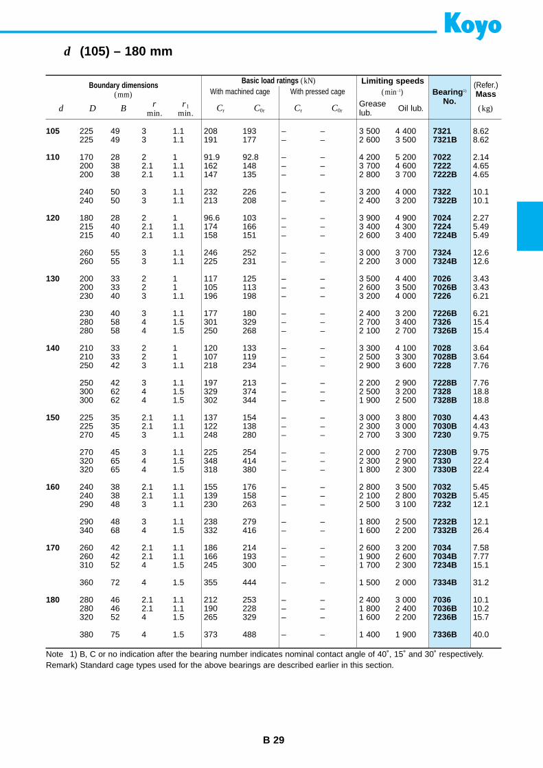
B 29
d (105) – 180 mm
Boundary dimensions(mm)
Limiting speeds(min–1) Bearing 1)
No.
(Refer.)Mass
d D Br
min.r1
min.Cr C0rCr C0r (kg)Grease
lub. Oil lub.
105
110
120
130
140
150
160
170
180
73217321B
702272227222B
73227322B
702472247224B
73247324B
70267026B7226
7226B73267326B
70287028B7228
7228B73287328B
70307030B7230
7230B73307330B
70327032B7232
7232B7332B
70347034B7234B
7334B
70367036B7236B
7336B
225 49 3 1.1 208 193 – – 3 500 4 400225 49 3 1.1 191 177 – – 2 600 3 500
170 28 2 1 91.9 92.8 – – 4 200 5 200200 38 2.1 1.1 162 148 – – 3 700 4 600200 38 2.1 1.1 147 135 – – 2 800 3 700
240 50 3 1.1 232 226 – – 3 200 4 000240 50 3 1.1 213 208 – – 2 400 3 200
180 28 2 1 96.6 103 – – 3 900 4 900215 40 2.1 1.1 174 166 – – 3 400 4 300215 40 2.1 1.1 158 151 – – 2 600 3 400
260 55 3 1.1 246 252 – – 3 000 3 700260 55 3 1.1 225 231 – – 2 200 3 000
200 33 2 1 117 125 – – 3 500 4 400200 33 2 1 105 113 – – 2 600 3 500230 40 3 1.1 196 198 – – 3 200 4 000
230 40 3 1.1 177 180 – – 2 400 3 200280 58 4 1.5 301 329 – – 2 700 3 400280 58 4 1.5 250 268 – – 2 100 2 700
210 33 2 1 120 133 – – 3 300 4 100210 33 2 1 107 119 – – 2 500 3 300250 42 3 1.1 218 234 – – 2 900 3 600
250 42 3 1.1 197 213 – – 2 200 2 900300 62 4 1.5 329 374 – – 2 500 3 200300 62 4 1.5 302 344 – – 1 900 2 500
225 35 2.1 1.1 137 154 – – 3 000 3 800225 35 2.1 1.1 122 138 – – 2 300 3 000270 45 3 1.1 248 280 – – 2 700 3 300
270 45 3 1.1 225 254 – – 2 000 2 700320 65 4 1.5 348 414 – – 2 300 2 900320 65 4 1.5 318 380 – – 1 800 2 300
240 38 2.1 1.1 155 176 – – 2 800 3 500240 38 2.1 1.1 139 158 – – 2 100 2 800290 48 3 1.1 230 263 – – 2 500 3 100
290 48 3 1.1 238 279 – – 1 800 2 500340 68 4 1.5 332 416 – – 1 600 2 200
260 42 2.1 1.1 186 214 – – 2 600 3 200260 42 2.1 1.1 166 193 – – 1 900 2 600310 52 4 1.5 245 300 – – 1 700 2 300
360 72 4 1.5 355 444 – – 1 500 2 000
280 46 2.1 1.1 212 253 – – 2 400 3 000280 46 2.1 1.1 190 228 – – 1 800 2 400320 52 4 1.5 265 329 – – 1 600 2 200
380 75 4 1.5 373 488 – – 1 400 1 900
8.628.62
2.144.654.65
10.110.1
2.275.495.49
12.612.6
3.433.436.21
6.2115.415.4
3.643.647.76
7.7618.818.8
4.434.439.75
9.7522.422.4
5.455.4512.1
12.126.4
7.587.7715.1
31.2
10.110.215.7
40.0
Note 1) B, C or no indication after the bearing number indicates nominal contact angle of 40˚, 15˚ and 30˚ respectively.Remark) Standard cage types used for the above bearings are described earlier in this section.
Basic load ratings (kN)With machined cage With pressed cage
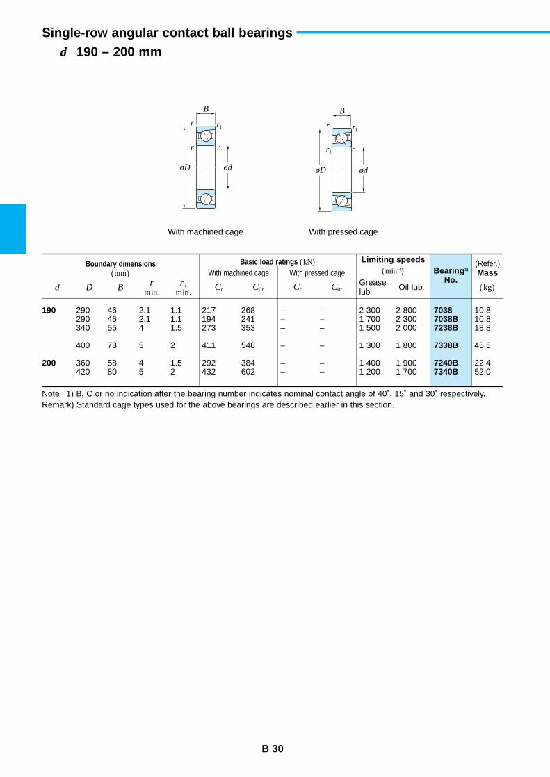
rr
r
øD ød
r1
r
r
øD ød
r1
r1
With machined cage With pressed cage
B B
B 30
d 190 – 200 mmSingle-row angular contact ball bearings
Boundary dimensions(mm)
Basic load ratings (kN)With machined cage With pressed cage
Limiting speeds(min–1) Bearing 1)
No.
(Refer.)Mass
d D Br
min.r1
min.Cr C0rCr C0r (kg)Grease
lub. Oil lub.
190
200
70387038B7238B
7338B
7240B7340B
290 46 2.1 1.1 217 268 – – 2 300 2 800290 46 2.1 1.1 194 241 – – 1 700 2 300340 55 4 1.5 273 353 – – 1 500 2 000
400 78 5 2 411 548 – – 1 300 1 800
360 58 4 1.5 292 384 – – 1 400 1 900420 80 5 2 432 602 – – 1 200 1 700
10.810.818.8
45.5
22.452.0
Note 1) B, C or no indication after the bearing number indicates nominal contact angle of 40˚, 15˚ and 30˚ respectively.Remark) Standard cage types used for the above bearings are described earlier in this section.

B 31
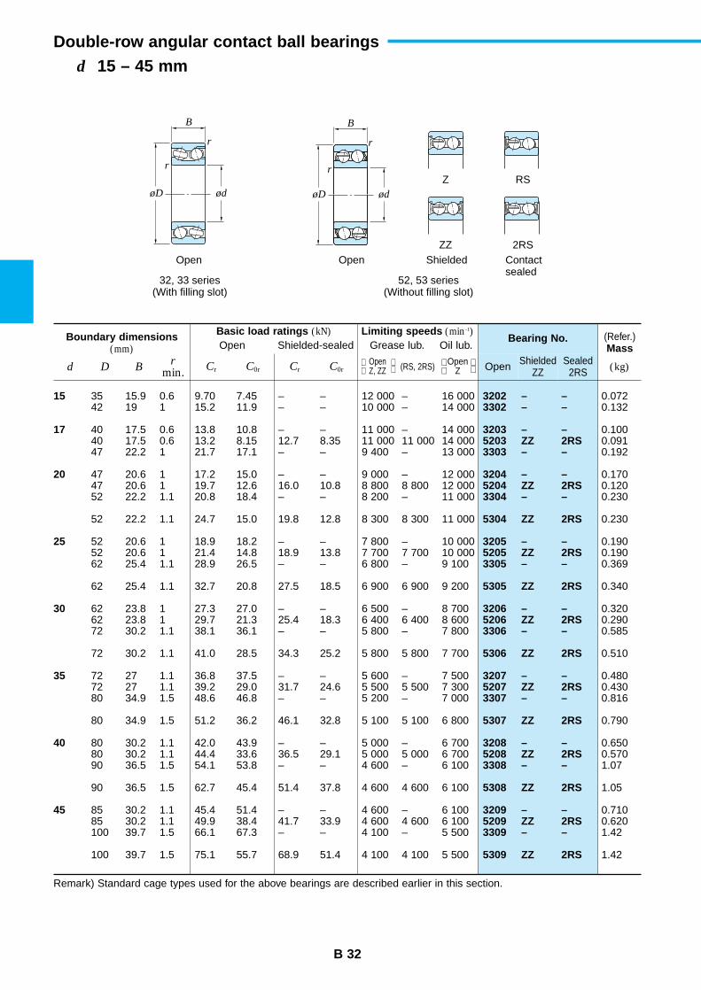
r
r
øD ød
r
r
øD ød
Z RS
ZZ 2RSOpen Open Shielded Contact
sealed32, 33 series
(With filling slot)52, 53 series
(Without filling slot)
B B
B 32
d 15 – 45 mmDouble-row angular contact ball bearings
Boundary dimensions(mm)
Basic load ratings (kN)Open Shielded-sealed
Limiting speeds (min–1)Grease lub. Oil lub.
Bearing No. (Refer.)Mass
d D Br
min. Cr C0r Cr C0r Open ShieldedZZ
Sealed2RS (kg) Open
Z, ZZ (RS, 2RS) Open Z
15
17
20
25
30
35
40
45
3202 – –3302 – –
3203 – –5203 ZZ 2RS3303 – –
3204 – –5204 ZZ 2RS3304 – –
5304 ZZ 2RS
3205 – –5205 ZZ 2RS3305 – –
5305 ZZ 2RS
3206 – –5206 ZZ 2RS3306 – –
5306 ZZ 2RS
3207 – –5207 ZZ 2RS3307 – –
5307 ZZ 2RS
3208 – –5208 ZZ 2RS3308 – –
5308 ZZ 2RS
3209 – –5209 ZZ 2RS3309 – –
5309 ZZ 2RS
35 15.9 0.6 9.70 7.45 – – 12 000 – 16 00042 19 1 15.2 11.9 – – 10 000 – 14 000
40 17.5 0.6 13.8 10.8 – – 11 000 – 14 00040 17.5 0.6 13.2 8.15 12.7 8.35 11 000 11 000 14 00047 22.2 1 21.7 17.1 – – 9 400 – 13 000
47 20.6 1 17.2 15.0 – – 9 000 – 12 00047 20.6 1 19.7 12.6 16.0 10.8 8 800 8 800 12 00052 22.2 1.1 20.8 18.4 – – 8 200 – 11 000
52 22.2 1.1 24.7 15.0 19.8 12.8 8 300 8 300 11 000
52 20.6 1 18.9 18.2 – – 7 800 – 10 00052 20.6 1 21.4 14.8 18.9 13.8 7 700 7 700 10 00062 25.4 1.1 28.9 26.5 – – 6 800 – 9 100
62 25.4 1.1 32.7 20.8 27.5 18.5 6 900 6 900 9 200
62 23.8 1 27.3 27.0 – – 6 500 – 8 70062 23.8 1 29.7 21.3 25.4 18.3 6 400 6 400 8 60072 30.2 1.1 38.1 36.1 – – 5 800 – 7 800
72 30.2 1.1 41.0 28.5 34.3 25.2 5 800 5 800 7 700
72 27 1.1 36.8 37.5 – – 5 600 – 7 50072 27 1.1 39.2 29.0 31.7 24.6 5 500 5 500 7 30080 34.9 1.5 48.6 46.8 – – 5 200 – 7 000
80 34.9 1.5 51.2 36.2 46.1 32.8 5 100 5 100 6 800
80 30.2 1.1 42.0 43.9 – – 5 000 – 6 70080 30.2 1.1 44.4 33.6 36.5 29.1 5 000 5 000 6 70090 36.5 1.5 54.1 53.8 – – 4 600 – 6 100
90 36.5 1.5 62.7 45.4 51.4 37.8 4 600 4 600 6 100
85 30.2 1.1 45.4 51.4 – – 4 600 – 6 10085 30.2 1.1 49.9 38.4 41.7 33.9 4 600 4 600 6 100100 39.7 1.5 66.1 67.3 – – 4 100 – 5 500
100 39.7 1.5 75.1 55.7 68.9 51.4 4 100 4 100 5 500
0.0720.132
0.1000.0910.192
0.1700.1200.230
0.230
0.1900.1900.369
0.340
0.3200.2900.585
0.510
0.4800.4300.816
0.790
0.6500.5701.07
1.05
0.7100.6201.42
1.42
Remark) Standard cage types used for the above bearings are described earlier in this section.
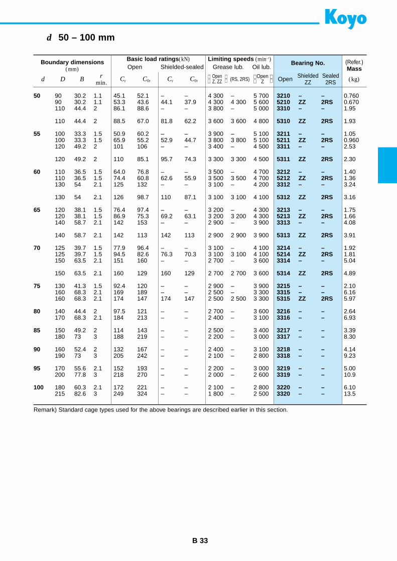
B 33
d 50 – 100 mm
Boundary dimensions(mm)
Basic load ratings (kN)Open Shielded-sealed
Limiting speeds (min–1)Grease lub. Oil lub.
Bearing No. (Refer.)Mass
d D Br
min.Cr C0r Cr C0r Open Shielded
ZZSealed
2RS (kg) Open Z, ZZ (RS, 2RS) Open
Z
50
55
60
65
70
75
80
85
90
95
100
3210 – –5210 ZZ 2RS3310 – –
5310 ZZ 2RS
3211 – –5211 ZZ 2RS3311 – –
5311 ZZ 2RS
3212 – –5212 ZZ 2RS3312 – –
5312 ZZ 2RS
3213 – –5213 ZZ 2RS3313 – –
5313 ZZ 2RS
3214 – –5214 ZZ 2RS3314 – –
5314 ZZ 2RS
3215 – –3315 – –5315 ZZ 2RS
3216 – –3316 – –
3217 – –3317 – –
3218 – –3318 – –
3219 – –3319 – –
3220 – –3320 – –
90 30.2 1.1 45.1 52.1 – – 4 300 – 5 70090 30.2 1.1 53.3 43.6 44.1 37.9 4 300 4 300 5 600110 44.4 2 86.1 88.6 – – 3 800 – 5 000
110 44.4 2 88.5 67.0 81.8 62.2 3 600 3 600 4 800
100 33.3 1.5 50.9 60.2 – – 3 900 – 5 100100 33.3 1.5 65.9 55.2 52.9 44.7 3 800 3 800 5 100120 49.2 2 101 106 – – 3 400 – 4 500
120 49.2 2 110 85.1 95.7 74.3 3 300 3 300 4 500
110 36.5 1.5 64.0 76.8 – – 3 500 – 4 700110 36.5 1.5 74.4 60.8 62.6 55.9 3 500 3 500 4 700130 54 2.1 125 132 – – 3 100 – 4 200
130 54 2.1 126 98.7 110 87.1 3 100 3 100 4 100
120 38.1 1.5 76.4 97.4 – – 3 200 – 4 300120 38.1 1.5 86.9 75.3 69.2 63.1 3 200 3 200 4 300140 58.7 2.1 142 153 – – 2 900 – 3 900
140 58.7 2.1 142 113 142 113 2 900 2 900 3 900
125 39.7 1.5 77.9 96.4 – – 3 100 – 4 100125 39.7 1.5 94.5 82.6 76.3 70.3 3 100 3 100 4 100150 63.5 2.1 151 160 – – 2 700 – 3 600
150 63.5 2.1 160 129 160 129 2 700 2 700 3 600
130 41.3 1.5 92.4 120 – – 2 900 – 3 900160 68.3 2.1 169 189 – – 2 500 – 3 300160 68.3 2.1 174 147 174 147 2 500 2 500 3 300
140 44.4 2 97.5 121 – – 2 700 – 3 600170 68.3 2.1 184 213 – – 2 400 – 3 100
150 49.2 2 114 143 – – 2 500 – 3 400180 73 3 188 219 – – 2 200 – 3 000
160 52.4 2 132 167 – – 2 400 – 3 100190 73 3 205 242 – – 2 100 – 2 800
170 55.6 2.1 152 193 – – 2 200 – 3 000200 77.8 3 218 270 – – 2 000 – 2 600
180 60.3 2.1 172 221 – – 2 100 – 2 800215 82.6 3 249 324 – – 1 800 – 2 500
0.7600.6701.95
1.93
1.050.9602.53
2.30
1.401.363.24
3.16
1.751.664.08
3.91
1.921.815.04
4.89
2.106.165.97
2.646.93
3.398.30
4.149.23
5.0010.9
6.1013.5
Remark) Standard cage types used for the above bearings are described earlier in this section.
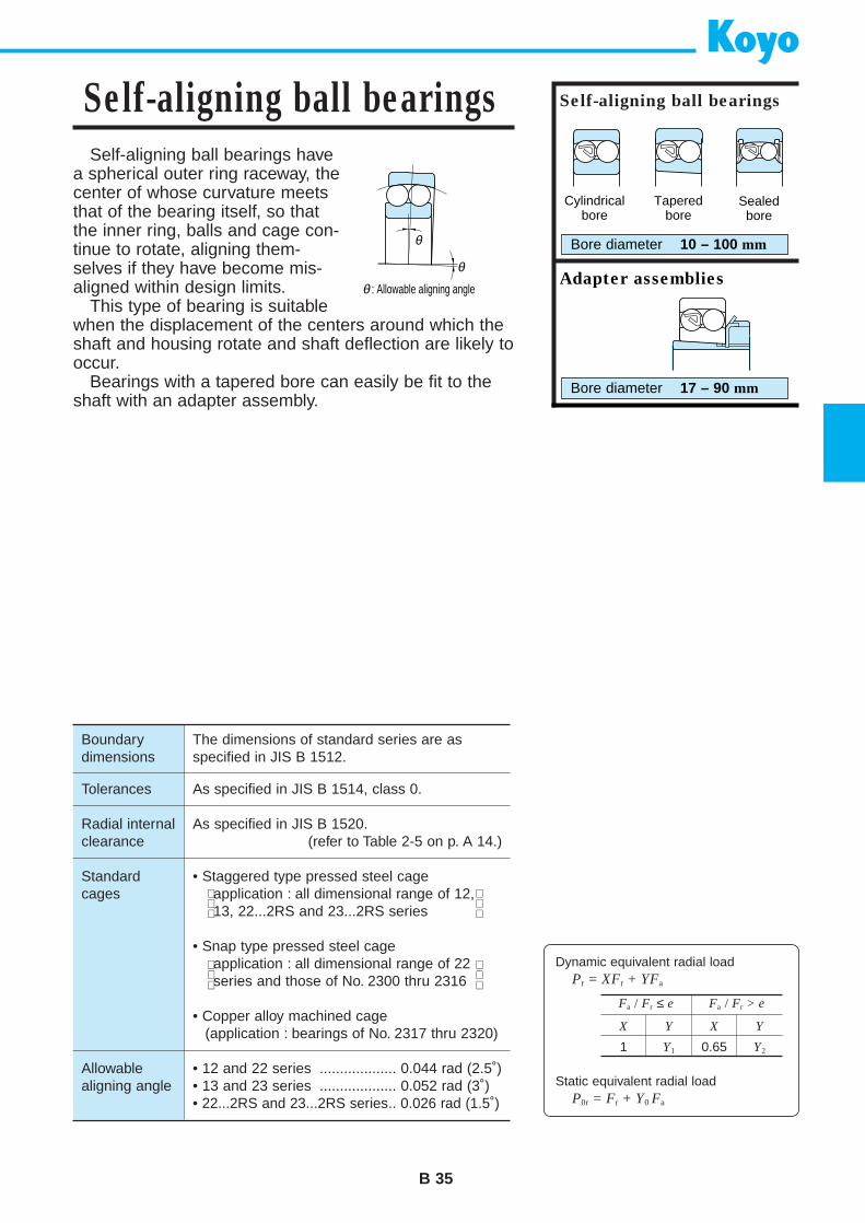
Dynamic equivalent radial loadPr = XFr + YFa
Static equivalent radial loadP0r = Fr + Y0 Fa
Self-aligning ball bearings havea spherical outer ring raceway, thecenter of whose curvature meetsthat of the bearing itself, so thatthe inner ring, balls and cage con-tinue to rotate, aligning them-selves if they have become mis-aligned within design limits.
This type of bearing is suitablewhen the displacement of the centers around which theshaft and housing rotate and shaft deflection are likely tooccur.
Bearings with a tapered bore can easily be fit to theshaft with an adapter assembly.
B 35
Self-aligning ball bearings Self-aligning ball bearings
Bore diameter 10 – 100 mm
Adapter assemblies
Bore diameter 17 – 90 mm
θ
θ
θ
: Allowable aligning angle
Boundarydimensions
Tolerances
Radial internalclearance
Standardcages
Allowablealigning angle
The dimensions of standard series are asspecified in JIS B 1512.
As specified in JIS B 1514, class 0.
As specified in JIS B 1520.(refer to Table 2-5 on p. A 14.)
• Staggered type pressed steel cageapplication : all dimensional range of 12,13, 22...2RS and 23...2RS series
• Snap type pressed steel cageapplication : all dimensional range of 22series and those of No. 2300 thru 2316
• Copper alloy machined cage(application : bearings of No. 2317 thru 2320)
• 12 and 22 series ................... 0.044 rad (2.5˚)• 13 and 23 series ................... 0.052 rad (3˚)• 22...2RS and 23...2RS series.. 0.026 rad (1.5˚)
Fa / Fr ≤ e Fa / Fr > e
X Y X Y
1 Y1 0.65 Y2
Cylindricalbore
Taperedbore
Sealedbore
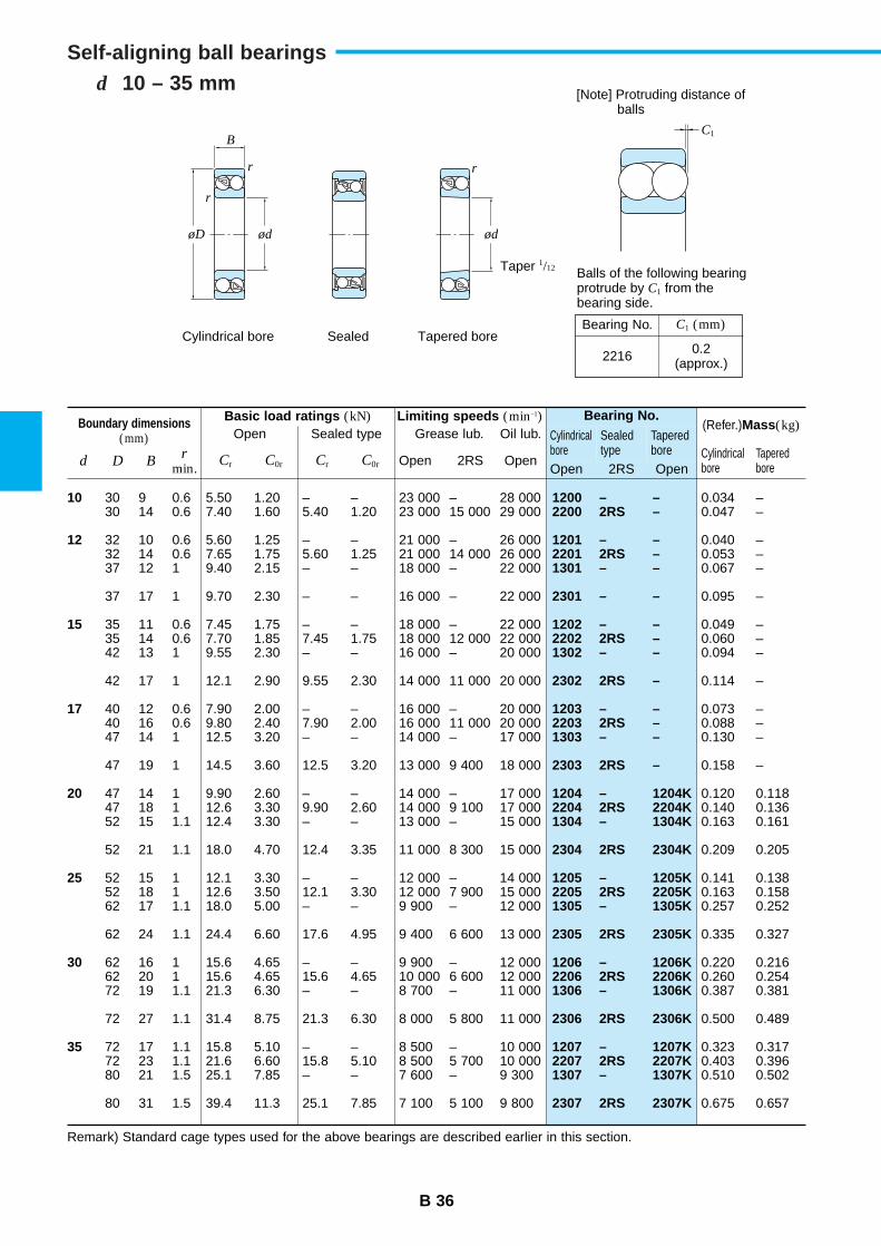
B 36
d 10 – 35 mmSelf-aligning ball bearings
Boundary dimensions(mm)
Basic load ratings (kN)Open Sealed type
Limiting speeds (min–1)Grease lub. Oil lub.
Bearing No.
Cylindricalbore
Sealedtype
Taperedbore
(Refer.)Mass(kg)
d D Br
min.Cr C0r Cr C0r Open 2RS Open
Cylindricalbore
TaperedboreOpen 2RS Open
10
12
15
17
20
25
30
35
1200 – –2200 2RS –
1201 – –2201 2RS –1301 – –
2301 – –
1202 – –2202 2RS –1302 – –
2302 2RS –
1203 – –2203 2RS –1303 – –
2303 2RS –
1204 – 1204K2204 2RS 2204K1304 – 1304K
2304 2RS 2304K
1205 – 1205K2205 2RS 2205K1305 – 1305K
2305 2RS 2305K
1206 – 1206K2206 2RS 2206K1306 – 1306K
2306 2RS 2306K
1207 – 1207K2207 2RS 2207K1307 – 1307K
2307 2RS 2307K
30 9 0.6 5.50 1.20 – – 23 000 – 28 00030 14 0.6 7.40 1.60 5.40 1.20 23 000 15 000 29 000
32 10 0.6 5.60 1.25 – – 21 000 – 26 00032 14 0.6 7.65 1.75 5.60 1.25 21 000 14 000 26 00037 12 1 9.40 2.15 – – 18 000 – 22 000
37 17 1 9.70 2.30 – – 16 000 – 22 000
35 11 0.6 7.45 1.75 – – 18 000 – 22 00035 14 0.6 7.70 1.85 7.45 1.75 18 000 12 000 22 00042 13 1 9.55 2.30 – – 16 000 – 20 000
42 17 1 12.1 2.90 9.55 2.30 14 000 11 000 20 000
40 12 0.6 7.90 2.00 – – 16 000 – 20 00040 16 0.6 9.80 2.40 7.90 2.00 16 000 11 000 20 00047 14 1 12.5 3.20 – – 14 000 – 17 000
47 19 1 14.5 3.60 12.5 3.20 13 000 9 400 18 000
47 14 1 9.90 2.60 – – 14 000 – 17 00047 18 1 12.6 3.30 9.90 2.60 14 000 9 100 17 00052 15 1.1 12.4 3.30 – – 13 000 – 15 000
52 21 1.1 18.0 4.70 12.4 3.35 11 000 8 300 15 000
52 15 1 12.1 3.30 – – 12 000 – 14 00052 18 1 12.6 3.50 12.1 3.30 12 000 7 900 15 00062 17 1.1 18.0 5.00 – – 9 900 – 12 000
62 24 1.1 24.4 6.60 17.6 4.95 9 400 6 600 13 000
62 16 1 15.6 4.65 – – 9 900 – 12 00062 20 1 15.6 4.65 15.6 4.65 10 000 6 600 12 00072 19 1.1 21.3 6.30 – – 8 700 – 11 000
72 27 1.1 31.4 8.75 21.3 6.30 8 000 5 800 11 000
72 17 1.1 15.8 5.10 – – 8 500 – 10 00072 23 1.1 21.6 6.60 15.8 5.10 8 500 5 700 10 00080 21 1.5 25.1 7.85 – – 7 600 – 9 300
80 31 1.5 39.4 11.3 25.1 7.85 7 100 5 100 9 800
0.034 –0.047 –
0.040 –0.053 –0.067 –
0.095 –
0.049 –0.060 –0.094 –
0.114 –
0.073 –0.088 –0.130 –
0.158 –
0.120 0.1180.140 0.1360.163 0.161
0.209 0.205
0.141 0.1380.163 0.1580.257 0.252
0.335 0.327
0.220 0.2160.260 0.2540.387 0.381
0.500 0.489
0.323 0.3170.403 0.3960.510 0.502
0.675 0.657
Remark) Standard cage types used for the above bearings are described earlier in this section.
C1
r r
r
øD ød ød
Taper 1/12
Cylindrical bore Sealed Tapered bore
Balls of the following bearingprotrude by C1 from thebearing side.
[Note] Protruding distance of balls
B
Bearing No.
2216 0.2(approx.)
C1 (mm)
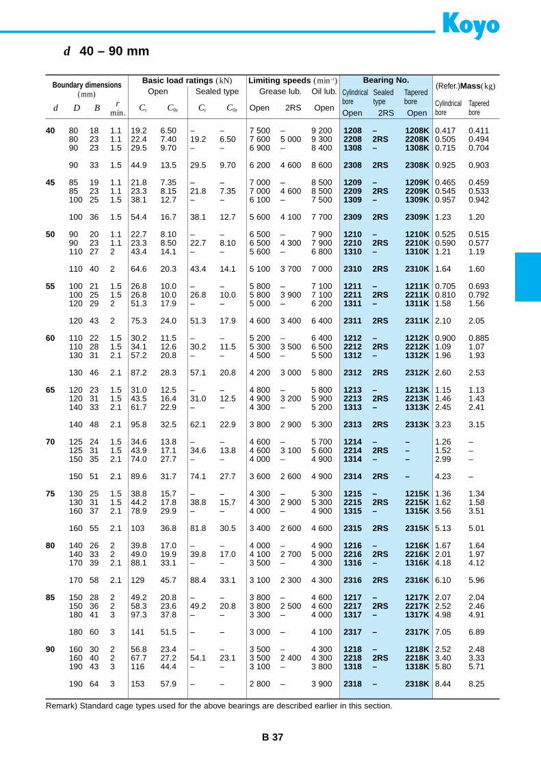
B 37
d 40 – 90 mm
Boundary dimensions(mm)
Basic load ratings (kN)Open Sealed type
Limiting speeds (min–1)Grease lub. Oil lub.
Bearing No.
Cylindricalbore
Sealedtype
Taperedbore
(Refer.)Mass(kg)
d D Br
min.Cr C0r Cr C0r Open 2RS Open
Cylindricalbore
TaperedboreOpen 2RS Open
40
45
50
55
60
65
70
75
80
85
90
1208 – 1208K2208 2RS 2208K1308 – 1308K
2308 2RS 2308K
1209 – 1209K2209 2RS 2209K1309 – 1309K
2309 2RS 2309K
1210 – 1210K2210 2RS 2210K1310 – 1310K
2310 2RS 2310K
1211 – 1211K2211 2RS 2211K1311 – 1311K
2311 2RS 2311K
1212 – 1212K2212 2RS 2212K1312 – 1312K
2312 2RS 2312K
1213 – 1213K2213 2RS 2213K1313 – 1313K
2313 2RS 2313K
1214 – –2214 2RS –1314 – –
2314 2RS –
1215 – 1215K2215 2RS 2215K1315 – 1315K
2315 2RS 2315K
1216 – 1216K2216 2RS 2216K1316 – 1316K
2316 2RS 2316K
1217 – 1217K2217 2RS 2217K1317 – 1317K
2317 – 2317K
1218 – 1218K2218 2RS 2218K1318 – 1318K
2318 – 2318K
80 18 1.1 19.2 6.50 – – 7 500 – 9 20080 23 1.1 22.4 7.40 19.2 6.50 7 600 5 000 9 30090 23 1.5 29.5 9.70 – – 6 900 – 8 400
90 33 1.5 44.9 13.5 29.5 9.70 6 200 4 600 8 600
85 19 1.1 21.8 7.35 – – 7 000 – 8 50085 23 1.1 23.3 8.15 21.8 7.35 7 000 4 600 8 500100 25 1.5 38.1 12.7 – – 6 100 – 7 500
100 36 1.5 54.4 16.7 38.1 12.7 5 600 4 100 7 700
90 20 1.1 22.7 8.10 – – 6 500 – 7 90090 23 1.1 23.3 8.50 22.7 8.10 6 500 4 300 7 900110 27 2 43.4 14.1 – – 5 600 – 6 800
110 40 2 64.6 20.3 43.4 14.1 5 100 3 700 7 000
100 21 1.5 26.8 10.0 – – 5 800 – 7 100100 25 1.5 26.8 10.0 26.8 10.0 5 800 3 900 7 100120 29 2 51.3 17.9 – – 5 000 – 6 200
120 43 2 75.3 24.0 51.3 17.9 4 600 3 400 6 400
110 22 1.5 30.2 11.5 – – 5 200 – 6 400110 28 1.5 34.1 12.6 30.2 11.5 5 300 3 500 6 500130 31 2.1 57.2 20.8 – – 4 500 – 5 500
130 46 2.1 87.2 28.3 57.1 20.8 4 200 3 000 5 800
120 23 1.5 31.0 12.5 – – 4 800 – 5 800120 31 1.5 43.5 16.4 31.0 12.5 4 900 3 200 5 900140 33 2.1 61.7 22.9 – – 4 300 – 5 200
140 48 2.1 95.8 32.5 62.1 22.9 3 800 2 900 5 300
125 24 1.5 34.6 13.8 – – 4 600 – 5 700125 31 1.5 43.9 17.1 34.6 13.8 4 600 3 100 5 600150 35 2.1 74.0 27.7 – – 4 000 – 4 900
150 51 2.1 89.6 31.7 74.1 27.7 3 600 2 600 4 900
130 25 1.5 38.8 15.7 – – 4 300 – 5 300130 31 1.5 44.2 17.8 38.8 15.7 4 300 2 900 5 300160 37 2.1 78.9 29.9 – – 4 000 – 4 900
160 55 2.1 103 36.8 81.8 30.5 3 400 2 600 4 600
140 26 2 39.8 17.0 – – 4 000 – 4 900140 33 2 49.0 19.9 39.8 17.0 4 100 2 700 5 000170 39 2.1 88.1 33.1 – – 3 500 – 4 300
170 58 2.1 129 45.7 88.4 33.1 3 100 2 300 4 300
150 28 2 49.2 20.8 – – 3 800 – 4 600150 36 2 58.3 23.6 49.2 20.8 3 800 2 500 4 600180 41 3 97.3 37.8 – – 3 300 – 4 000
180 60 3 141 51.5 – – 3 000 – 4 100
160 30 2 56.8 23.4 – – 3 500 – 4 300160 40 2 67.7 27.2 54.1 23.1 3 500 2 400 4 300190 43 3 116 44.4 – – 3 100 – 3 800
190 64 3 153 57.9 – – 2 800 – 3 900
0.417 0.4110.505 0.4940.715 0.704
0.925 0.903
0.465 0.4590.545 0.5330.957 0.942
1.23 1.20
0.525 0.5150.590 0.5771.21 1.19
1.64 1.60
0.705 0.6930.810 0.7921.58 1.56
2.10 2.05
0.900 0.8851.09 1.071.96 1.93
2.60 2.53
1.15 1.131.46 1.432.45 2.41
3.23 3.15
1.26 –1.52 –2.99 –
4.23 –
1.36 1.341.62 1.583.56 3.51
5.13 5.01
1.67 1.642.01 1.974.18 4.12
6.10 5.96
2.07 2.042.52 2.464.98 4.91
7.05 6.89
2.52 2.483.40 3.335.80 5.71
8.44 8.25
Remark) Standard cage types used for the above bearings are described earlier in this section.
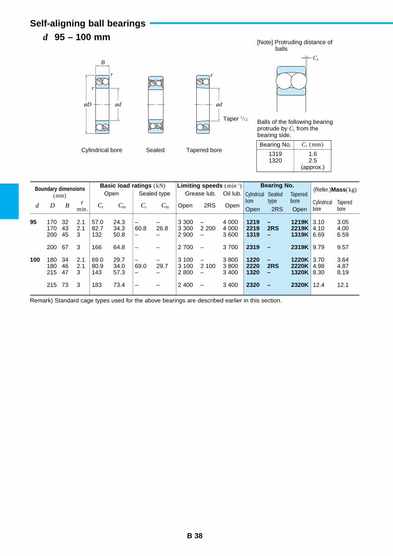
B 38
d 95 – 100 mmSelf-aligning ball bearings
Boundary dimensions(mm)
Basic load ratings (kN)Open Sealed type
Limiting speeds (min–1)Grease lub. Oil lub.
Bearing No.
Cylindricalbore
Sealedtype
Taperedbore
(Refer.)Mass(kg)
d D Br
min.Cr C0r Cr C0r Open 2RS Open
Cylindricalbore
TaperedboreOpen 2RS Open
95
100
1219 – 1219K2219 2RS 2219K1319 – 1319K
2319 – 2319K
1220 – 1220K2220 2RS 2220K1320 – 1320K
2320 – 2320K
170 32 2.1 57.0 24.3 – – 3 300 – 4 000170 43 2.1 82.7 34.3 60.8 26.8 3 300 2 200 4 000200 45 3 132 50.8 – – 2 900 – 3 600
200 67 3 166 64.8 – – 2 700 – 3 700
180 34 2.1 69.0 29.7 – – 3 100 – 3 800180 46 2.1 80.9 34.0 69.0 29.7 3 100 2 100 3 800215 47 3 143 57.3 – – 2 800 – 3 400
215 73 3 183 73.4 – – 2 400 – 3 400
3.10 3.054.10 4.006.69 6.59
9.79 9.57
3.70 3.644.98 4.878.30 8.19
12.4 12.1
Remark) Standard cage types used for the above bearings are described earlier in this section.
C1
r r
r
øD ød ød
Taper 1/12
Cylindrical bore Sealed Tapered bore
Balls of the following bearingprotrude by C1 from thebearing side.
[Note] Protruding distance of balls
B
Bearing No.
13191320
1.62.5
(approx.)
C1 (mm)

B 39
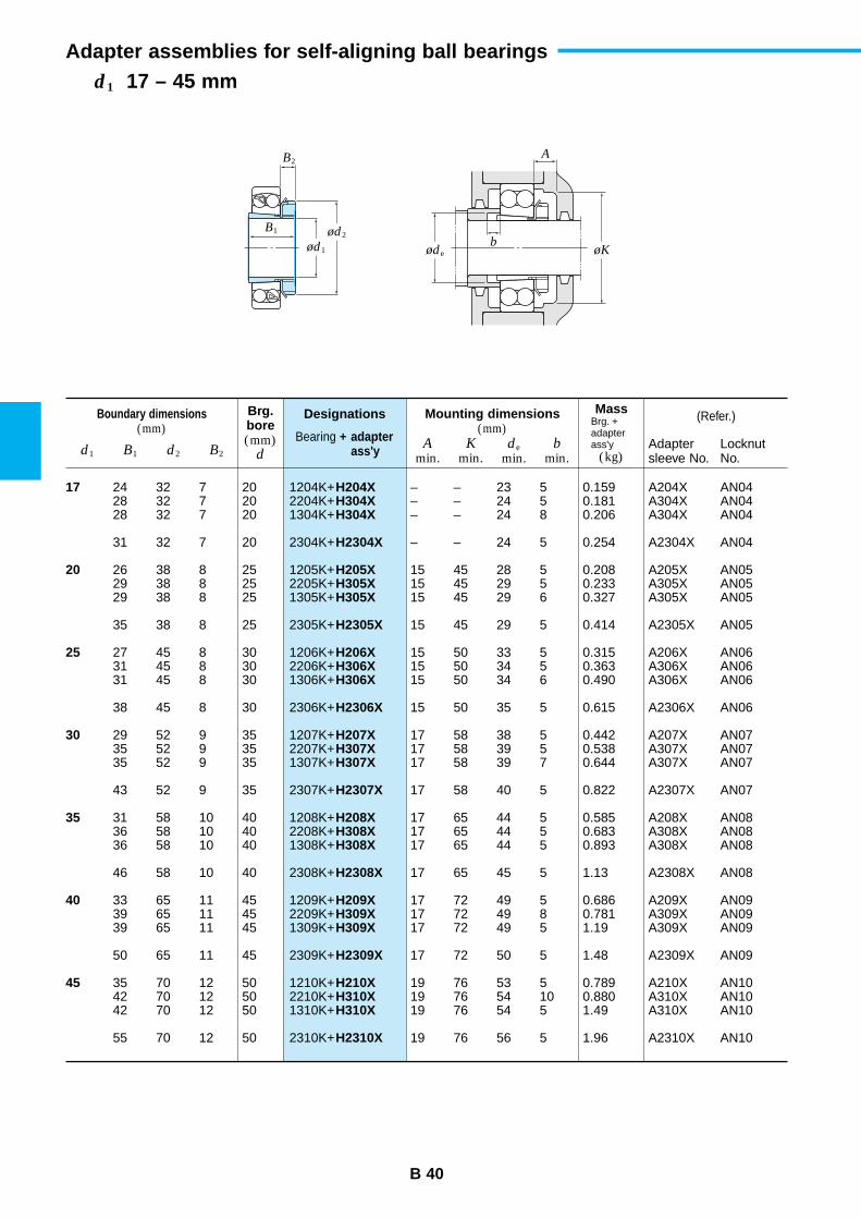
B 40
d1 17 – 45 mmAdapter assemblies for self-aligning ball bearings
Boundary dimensions(mm)
Designations
Bearing + adapter ass'y
(Refer.)
d1
Brg.bore(mm)
d
MassBrg. +adapterass'y
(kg)B1 d2 B2
Mounting dimensions(mm)
Amin.
Kmin.
de
min.b
min.Adaptersleeve No.
LocknutNo.
17
20
25
30
35
40
45
1204K+2204K+1304K+
2304K+
1205K+2205K+1305K+
2305K+
1206K+2206K+1306K+
2306K+
1207K+2207K+1307K+
2307K+
1208K+2208K+1308K+
2308K+
1209K+2209K+1309K+
2309K+
1210K+2210K+1310K+
2310K+
H204XH304XH304X
H2304X
H205XH305XH305X
H2305X
H206XH306XH306X
H2306X
H207XH307XH307X
H2307X
H208XH308XH308X
H2308X
H209XH309XH309X
H2309X
H210XH310XH310X
H2310X
24 32 7 2028 32 7 2028 32 7 20
31 32 7 20
26 38 8 2529 38 8 2529 38 8 25
35 38 8 25
27 45 8 3031 45 8 3031 45 8 30
38 45 8 30
29 52 9 3535 52 9 3535 52 9 35
43 52 9 35
31 58 10 4036 58 10 4036 58 10 40
46 58 10 40
33 65 11 4539 65 11 4539 65 11 45
50 65 11 45
35 70 12 5042 70 12 5042 70 12 50
55 70 12 50
– – 23 5 0.159 A204X AN04– – 24 5 0.181 A304X AN04– – 24 8 0.206 A304X AN04
– – 24 5 0.254 A2304X AN04
15 45 28 5 0.208 A205X AN0515 45 29 5 0.233 A305X AN0515 45 29 6 0.327 A305X AN05
15 45 29 5 0.414 A2305X AN05
15 50 33 5 0.315 A206X AN0615 50 34 5 0.363 A306X AN0615 50 34 6 0.490 A306X AN06
15 50 35 5 0.615 A2306X AN06
17 58 38 5 0.442 A207X AN0717 58 39 5 0.538 A307X AN0717 58 39 7 0.644 A307X AN07
17 58 40 5 0.822 A2307X AN07
17 65 44 5 0.585 A208X AN0817 65 44 5 0.683 A308X AN0817 65 44 5 0.893 A308X AN08
17 65 45 5 1.13 A2308X AN08
17 72 49 5 0.686 A209X AN0917 72 49 8 0.781 A309X AN0917 72 49 5 1.19 A309X AN09
17 72 50 5 1.48 A2309X AN09
19 76 53 5 0.789 A210X AN1019 76 54 10 0.880 A310X AN1019 76 54 5 1.49 A310X AN10
19 76 56 5 1.96 A2310X AN10
B2A
b
B1 ød2
øde øKød1
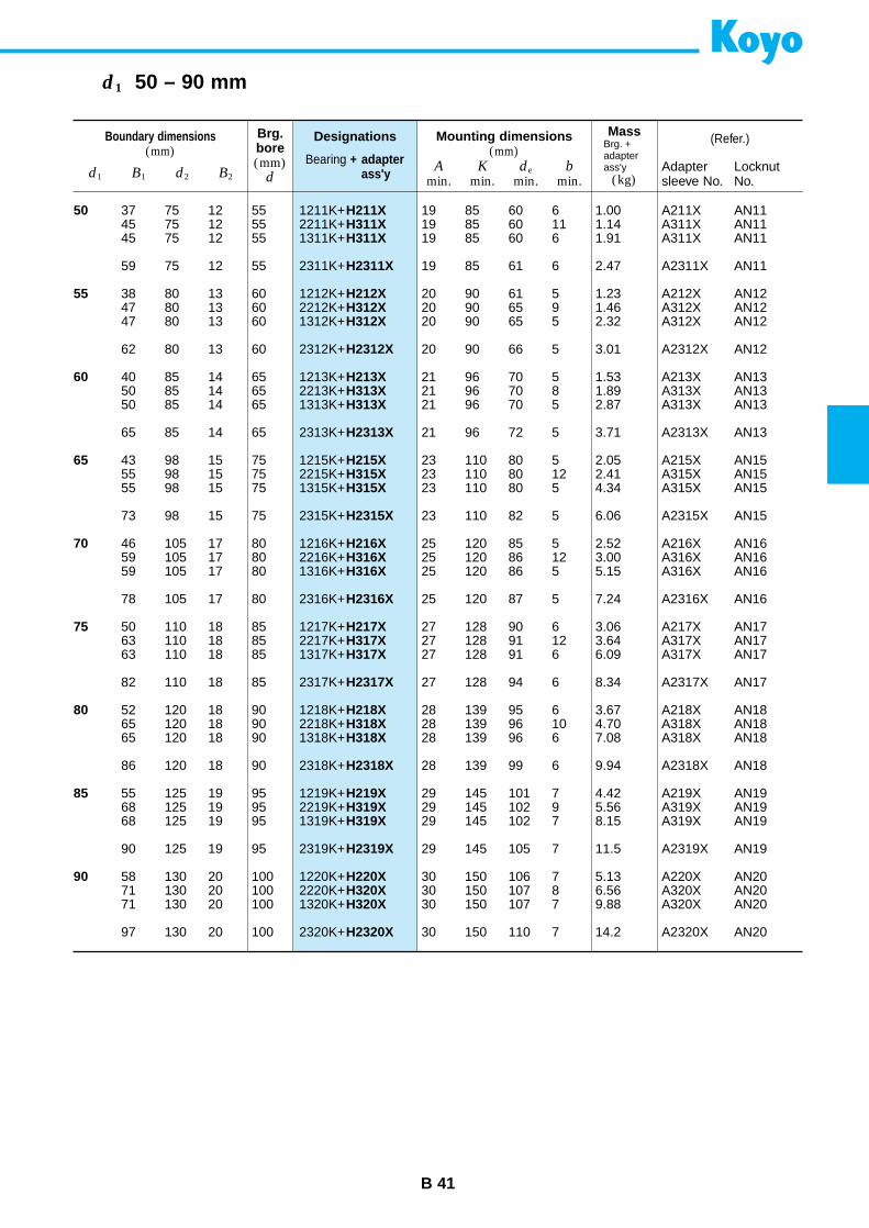
B 41
d1 50 – 90 mm
Boundary dimensions(mm)
Designations
Bearing + adapter ass'y
(Refer.)
d1
Brg.bore(mm)
d
MassBrg. +adapterass'y
(kg)B1 d2 B2
Mounting dimensions(mm)
Amin.
Kmin.
de
min.b
min.Adaptersleeve No.
LocknutNo.
50
55
60
65
70
75
80
85
90
1211K+2211K+1311K+
2311K+
1212K+2212K+1312K+
2312K+
1213K+2213K+1313K+
2313K+
1215K+2215K+1315K+
2315K+
1216K+2216K+1316K+
2316K+
1217K+2217K+1317K+
2317K+
1218K+2218K+1318K+
2318K+
1219K+2219K+1319K+
2319K+
1220K+2220K+1320K+
2320K+
H211XH311XH311X
H2311X
H212XH312XH312X
H2312X
H213XH313XH313X
H2313X
H215XH315XH315X
H2315X
H216XH316XH316X
H2316X
H217XH317XH317X
H2317X
H218XH318XH318X
H2318X
H219XH319XH319X
H2319X
H220XH320XH320X
H2320X
37 75 12 5545 75 12 5545 75 12 55
59 75 12 55
38 80 13 6047 80 13 6047 80 13 60
62 80 13 60
40 85 14 6550 85 14 6550 85 14 65
65 85 14 65
43 98 15 7555 98 15 7555 98 15 75
73 98 15 75
46 105 17 8059 105 17 8059 105 17 80
78 105 17 80
50 110 18 8563 110 18 8563 110 18 85
82 110 18 85
52 120 18 9065 120 18 9065 120 18 90
86 120 18 90
55 125 19 9568 125 19 9568 125 19 95
90 125 19 95
58 130 20 10071 130 20 10071 130 20 100
97 130 20 100
19 85 60 6 1.00 A211X AN1119 85 60 11 1.14 A311X AN1119 85 60 6 1.91 A311X AN11
19 85 61 6 2.47 A2311X AN11
20 90 61 5 1.23 A212X AN1220 90 65 9 1.46 A312X AN1220 90 65 5 2.32 A312X AN12
20 90 66 5 3.01 A2312X AN12
21 96 70 5 1.53 A213X AN1321 96 70 8 1.89 A313X AN1321 96 70 5 2.87 A313X AN13
21 96 72 5 3.71 A2313X AN13
23 110 80 5 2.05 A215X AN1523 110 80 12 2.41 A315X AN1523 110 80 5 4.34 A315X AN15
23 110 82 5 6.06 A2315X AN15
25 120 85 5 2.52 A216X AN1625 120 86 12 3.00 A316X AN1625 120 86 5 5.15 A316X AN16
25 120 87 5 7.24 A2316X AN16
27 128 90 6 3.06 A217X AN1727 128 91 12 3.64 A317X AN1727 128 91 6 6.09 A317X AN17
27 128 94 6 8.34 A2317X AN17
28 139 95 6 3.67 A218X AN1828 139 96 10 4.70 A318X AN1828 139 96 6 7.08 A318X AN18
28 139 99 6 9.94 A2318X AN18
29 145 101 7 4.42 A219X AN1929 145 102 9 5.56 A319X AN1929 145 102 7 8.15 A319X AN19
29 145 105 7 11.5 A2319X AN19
30 150 106 7 5.13 A220X AN2030 150 107 8 6.56 A320X AN2030 150 107 7 9.88 A320X AN20
30 150 110 7 14.2 A2320X AN20
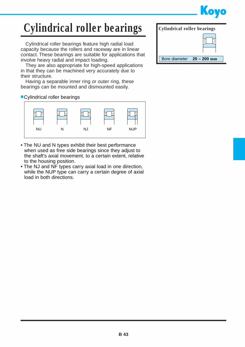
Cylindrical roller bearings feature high radial loadcapacity because the rollers and raceway are in linearcontact. These bearings are suitable for applications thatinvolve heavy radial and impact loading.
They are also appropriate for high-speed applicationsin that they can be machined very accurately due totheir structure.
Having a separable inner ring or outer ring, thesebearings can be mounted and dismounted easily.
Cylindrical roller bearings
B 43
Cylindrical roller bearings Cylindrical roller bearings
Bore diameter 20 – 200 mm
NU N NJ NF NUP
• The NU and N types exhibit their best performancewhen used as free side bearings since they adjust tothe shaft's axial movement, to a certain extent, relativeto the housing position.
• The NJ and NF types carry axial load in one direction,while the NUP type can carry a certain degree of axialload in both directions.
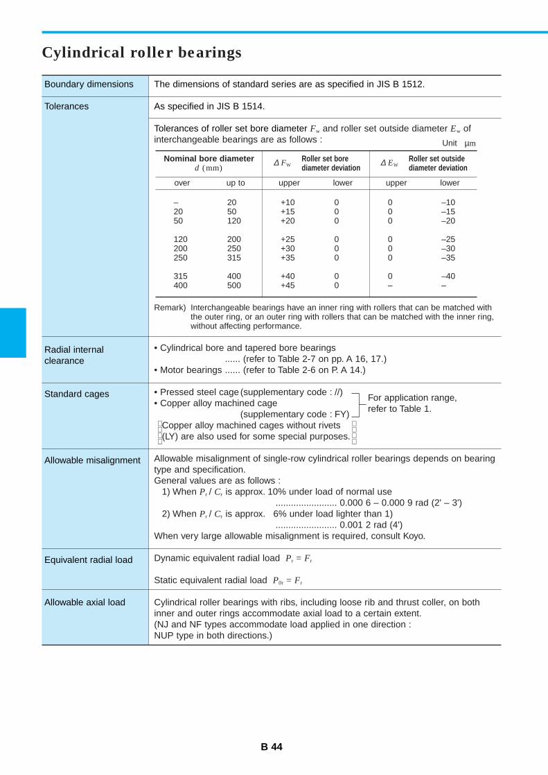
B 44
Boundary dimensions
Tolerances
Radial internal clearance
Standard cages
Allowable misalignment
Equivalent radial load
Allowable axial load
The dimensions of standard series are as specified in JIS B 1512.
As specified in JIS B 1514.
Tolerances of roller set bore diameter Fw and roller set outside diameter Ew of interchangeable bearings are as follows :
Remark) Interchangeable bearings have an inner ring with rollers that can be matched withthe outer ring, or an outer ring with rollers that can be matched with the inner ring,without affecting performance.
• Cylindrical bore and tapered bore bearings...... (refer to Table 2-7 on pp. A 16, 17.)
• Motor bearings ...... (refer to Table 2-6 on P. A 14.)
• Pressed steel cage (supplementary code : //)• Copper alloy machined cage
(supplementary code : FY)Copper alloy machined cages without rivets(LY) are also used for some special purposes.
Allowable misalignment of single-row cylindrical roller bearings depends on bearingtype and specification.General values are as follows :
1) When Pr / Cr is approx. 10% under load of normal use........................ 0.000 6 – 0.000 9 rad (2' – 3')
2) When Pr / Cr is approx. 6% under load lighter than 1)........................ 0.001 2 rad (4')
When very large allowable misalignment is required, consult Koyo.
Dynamic equivalent radial load Pr = Fr
Static equivalent radial load P0r = Fr
Cylindrical roller bearings with ribs, including loose rib and thrust coller, on bothinner and outer rings accommodate axial load to a certain extent.(NJ and NF types accommodate load applied in one direction :NUP type in both directions.)
Cylindrical roller bearings
Nominal bore diameterd (mm)
∆ FWRoller set borediameter deviation
– 20 +10 0 0 –1020 50 +15 0 0 –1550 120 +20 0 0 –20
120 200 +25 0 0 –25200 250 +30 0 0 –30250 315 +35 0 0 –35
315 400 +40 0 0 –40400 500 +45 0 – –
∆ EWRoller set outsidediameter deviation
over up to upper lower upper lower
For application range,refer to Table 1.
Unit µm
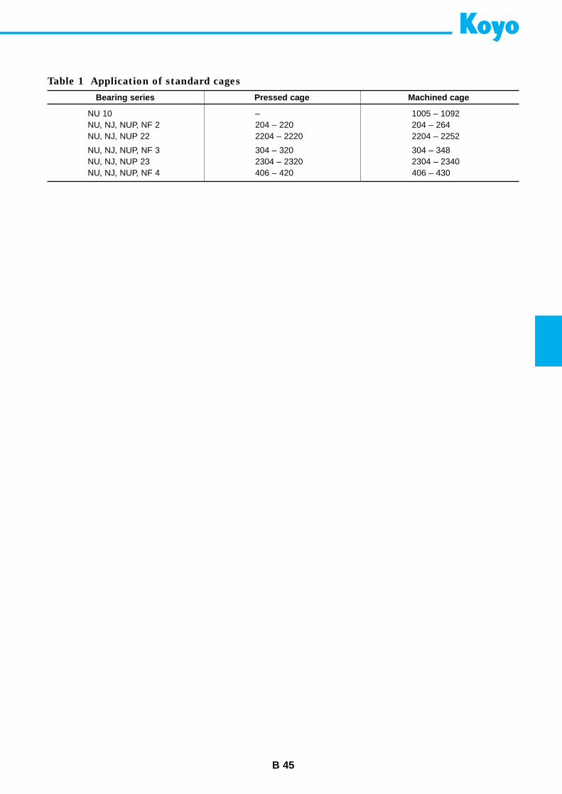
B 45
Bearing series Pressed cage Machined cage
NU 10 – 1005 – 1092NU, NJ, NUP, NF 2 204 – 220 204 – 264NU, NJ, NUP 22 2204 – 2220 2204 – 2252
NU, NJ, NUP, NF 3 304 – 320 304 – 348NU, NJ, NUP 23 2304 – 2320 2304 – 2340NU, NJ, NUP, NF 4 406 – 420 406 – 430
Table 1 Application of standard cages
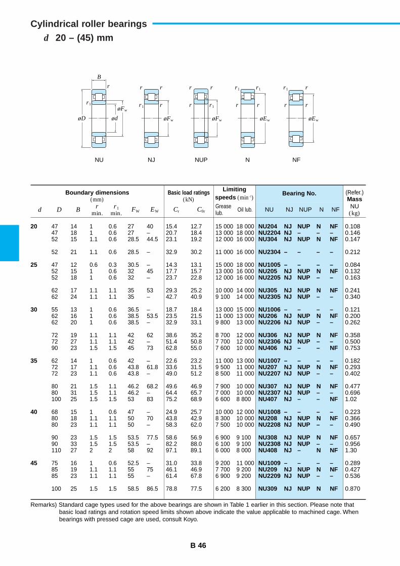
B 46
d 20 – (45) mmCylindrical roller bearings
Boundary dimensions(mm)
Basic load ratings(kN)
Limitingspeeds (min–1)
Bearing No. (Refer.)Mass
d D Br
min.r1
min.FW EW Cr C0r NU NJ NUP N NF NU
(kg)Greaselub. Oil lub.
20
25
30
35
40
45
NU204 NJ NUP N NFNU2204 NJ – – –NU304 NJ NUP N NF
NU2304 – – – –
NU1005 – – – –NU205 NJ NUP N NFNU2205 NJ NUP – –
NU305 NJ NUP N NFNU2305 NJ NUP – –
NU1006 – – – –NU206 NJ NUP N NFNU2206 NJ NUP – –
NU306 NJ NUP N NFNU2306 NJ NUP – –NU406 NJ – – NF
NU1007 – – – –NU207 NJ NUP N NFNU2207 NJ NUP – –
NU307 NJ NUP N NFNU2307 NJ NUP – –NU407 NJ – – NF
NU1008 – – – –NU208 NJ NUP N NFNU2208 NJ NUP – –
NU308 NJ NUP N NFNU2308 NJ NUP – –NU408 NJ – N NF
NU1009 – – – –NU209 NJ NUP N NFNU2209 NJ NUP – –
NU309 NJ NUP N NF
47 14 1 0.6 27 40 15.4 12.7 15 000 18 00047 18 1 0.6 27 – 20.7 18.4 13 000 18 00052 15 1.1 0.6 28.5 44.5 23.1 19.2 12 000 16 000
52 21 1.1 0.6 28.5 – 32.9 30.2 11 000 16 000
47 12 0.6 0.3 30.5 – 14.3 13.1 15 000 18 00052 15 1 0.6 32 45 17.7 15.7 13 000 16 00052 18 1 0.6 32 – 23.7 22.8 12 000 16 000
62 17 1.1 1.1 35 53 29.3 25.2 10 000 14 00062 24 1.1 1.1 35 – 42.7 40.9 9 100 14 000
55 13 1 0.6 36.5 – 18.7 18.4 13 000 15 00062 16 1 0.6 38.5 53.5 23.5 21.5 11 000 13 00062 20 1 0.6 38.5 – 32.9 33.1 9 800 13 000
72 19 1.1 1.1 42 62 38.6 35.2 8 700 12 00072 27 1.1 1.1 42 – 51.4 50.8 7 700 12 00090 23 1.5 1.5 45 73 62.8 55.0 7 600 10 000
62 14 1 0.6 42 – 22.6 23.2 11 000 13 00072 17 1.1 0.6 43.8 61.8 33.6 31.5 9 500 11 00072 23 1.1 0.6 43.8 – 49.0 51.2 8 500 11 000
80 21 1.5 1.1 46.2 68.2 49.6 46.9 7 900 10 00080 31 1.5 1.1 46.2 – 64.4 65.7 7 000 10 000100 25 1.5 1.5 53 83 75.2 68.9 6 600 8 800
68 15 1 0.6 47 – 24.9 25.7 10 000 12 00080 18 1.1 1.1 50 70 43.8 42.9 8 300 10 00080 23 1.1 1.1 50 – 58.3 62.0 7 500 10 000
90 23 1.5 1.5 53.5 77.5 58.6 56.9 6 900 9 10090 33 1.5 1.5 53.5 – 82.2 88.0 6 100 9 100110 27 2 2 58 92 97.1 89.1 6 000 8 000
75 16 1 0.6 52.5 – 31.0 33.8 9 200 11 00085 19 1.1 1.1 55 75 46.1 46.9 7 700 9 20085 23 1.1 1.1 55 – 61.4 67.8 6 900 9 200
100 25 1.5 1.5 58.5 86.5 78.8 77.5 6 200 8 300
0.1080.1460.147
0.212
0.0840.1320.163
0.2410.340
0.1210.2000.262
0.3580.5000.753
0.1820.2930.402
0.4770.6961.02
0.2230.3660.490
0.6570.9561.30
0.2890.4270.536
0.870
Remarks) Standard cage types used for the above bearings are shown in Table 1 earlier in this section. Please note thatbasic load ratings and rotation speed limits shown above indicate the value applicable to machined cage. Whenbearings with pressed cage are used, consult Koyo.
rr
r1
r
r
r
r
r
r1
r1
r
r1
r
r1
r
r
rr1
B
ødøD
øFw
øFw øFw øEw øEw
NU NJ NUP N NF
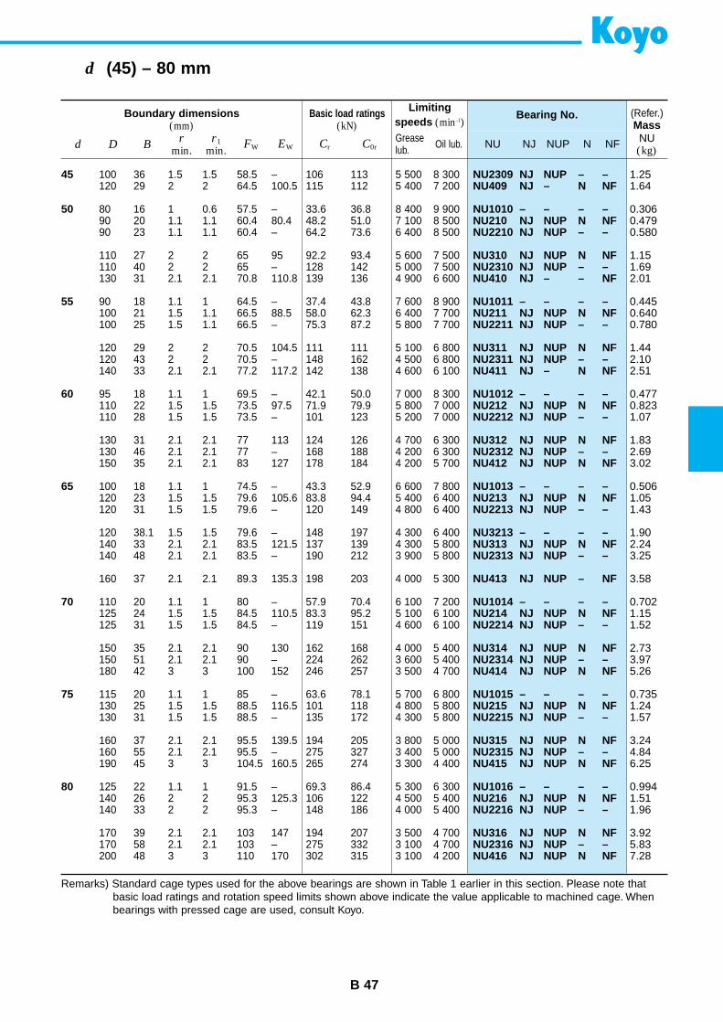
B 47
d (45) – 80 mm
Boundary dimensions(mm)
Basic load ratings(kN)
Limitingspeeds (min–1)
Bearing No. (Refer.)Mass
d D Br
min.r1
min.FW EW Cr C0r NU NJ NUP N NF NU
(kg)Greaselub. Oil lub.
45
50
55
60
65
70
75
80
NU2309 NJ NUP – –NU409 NJ – N NF
NU1010 – – – –NU210 NJ NUP N NFNU2210 NJ NUP – –
NU310 NJ NUP N NFNU2310 NJ NUP – –NU410 NJ – – NF
NU1011 – – – –NU211 NJ NUP N NFNU2211 NJ NUP – –
NU311 NJ NUP N NFNU2311 NJ NUP – –NU411 NJ – N NF
NU1012 – – – –NU212 NJ NUP N NFNU2212 NJ NUP – –
NU312 NJ NUP N NFNU2312 NJ NUP – –NU412 NJ NUP N NF
NU1013 – – – –NU213 NJ NUP N NFNU2213 NJ NUP – –
NU3213 – – – –NU313 NJ NUP N NFNU2313 NJ NUP – –
NU413 NJ NUP – NF
NU1014 – – – –NU214 NJ NUP N NFNU2214 NJ NUP – –
NU314 NJ NUP N NFNU2314 NJ NUP – –NU414 NJ NUP N NF
NU1015 – – – –NU215 NJ NUP N NFNU2215 NJ NUP – –
NU315 NJ NUP N NFNU2315 NJ NUP – –NU415 NJ NUP N NF
NU1016 – – – –NU216 NJ NUP N NFNU2216 NJ NUP – –
NU316 NJ NUP N NFNU2316 NJ NUP – –NU416 NJ NUP N NF
100 36 1.5 1.5 58.5 – 106 113 5 500 8 300120 29 2 2 64.5 100.5 115 112 5 400 7 200
80 16 1 0.6 57.5 – 33.6 36.8 8 400 9 90090 20 1.1 1.1 60.4 80.4 48.2 51.0 7 100 8 50090 23 1.1 1.1 60.4 – 64.2 73.6 6 400 8 500
110 27 2 2 65 95 92.2 93.4 5 600 7 500110 40 2 2 65 – 128 142 5 000 7 500130 31 2.1 2.1 70.8 110.8 139 136 4 900 6 600
90 18 1.1 1 64.5 – 37.4 43.8 7 600 8 900100 21 1.5 1.1 66.5 88.5 58.0 62.3 6 400 7 700100 25 1.5 1.1 66.5 – 75.3 87.2 5 800 7 700
120 29 2 2 70.5 104.5 111 111 5 100 6 800120 43 2 2 70.5 – 148 162 4 500 6 800140 33 2.1 2.1 77.2 117.2 142 138 4 600 6 100
95 18 1.1 1 69.5 – 42.1 50.0 7 000 8 300110 22 1.5 1.5 73.5 97.5 71.9 79.9 5 800 7 000110 28 1.5 1.5 73.5 – 101 123 5 200 7 000
130 31 2.1 2.1 77 113 124 126 4 700 6 300130 46 2.1 2.1 77 – 168 188 4 200 6 300150 35 2.1 2.1 83 127 178 184 4 200 5 700
100 18 1.1 1 74.5 – 43.3 52.9 6 600 7 800120 23 1.5 1.5 79.6 105.6 83.8 94.4 5 400 6 400120 31 1.5 1.5 79.6 – 120 149 4 800 6 400
120 38.1 1.5 1.5 79.6 – 148 197 4 300 6 400140 33 2.1 2.1 83.5 121.5 137 139 4 300 5 800140 48 2.1 2.1 83.5 – 190 212 3 900 5 800
160 37 2.1 2.1 89.3 135.3 198 203 4 000 5 300
110 20 1.1 1 80 – 57.9 70.4 6 100 7 200125 24 1.5 1.5 84.5 110.5 83.3 95.2 5 100 6 100125 31 1.5 1.5 84.5 – 119 151 4 600 6 100
150 35 2.1 2.1 90 130 162 168 4 000 5 400150 51 2.1 2.1 90 – 224 262 3 600 5 400180 42 3 3 100 152 246 257 3 500 4 700
115 20 1.1 1 85 – 63.6 78.1 5 700 6 800130 25 1.5 1.5 88.5 116.5 101 118 4 800 5 800130 31 1.5 1.5 88.5 – 135 172 4 300 5 800
160 37 2.1 2.1 95.5 139.5 194 205 3 800 5 000160 55 2.1 2.1 95.5 – 275 327 3 400 5 000190 45 3 3 104.5 160.5 265 274 3 300 4 400
125 22 1.1 1 91.5 – 69.3 86.4 5 300 6 300140 26 2 2 95.3 125.3 106 122 4 500 5 400140 33 2 2 95.3 – 148 186 4 000 5 400
170 39 2.1 2.1 103 147 194 207 3 500 4 700170 58 2.1 2.1 103 – 275 332 3 100 4 700200 48 3 3 110 170 302 315 3 100 4 200
1.251.64
0.3060.4790.580
1.151.692.01
0.4450.6400.780
1.442.102.51
0.4770.8231.07
1.832.693.02
0.5061.051.43
1.902.243.25
3.58
0.7021.151.52
2.733.975.26
0.7351.241.57
3.244.846.25
0.9941.511.96
3.925.837.28
Remarks) Standard cage types used for the above bearings are shown in Table 1 earlier in this section. Please note thatbasic load ratings and rotation speed limits shown above indicate the value applicable to machined cage. Whenbearings with pressed cage are used, consult Koyo.
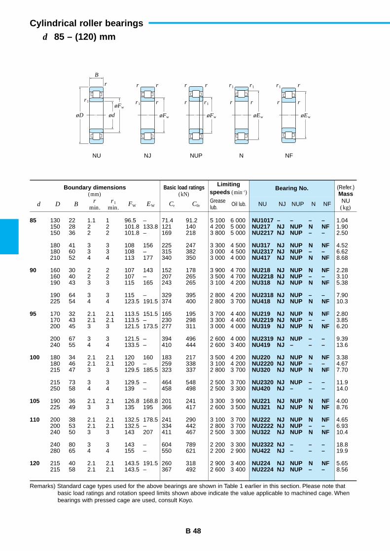
B 48
d 85 – (120) mmCylindrical roller bearings
Boundary dimensions(mm)
Basic load ratings(kN)
Limitingspeeds (min–1)
Bearing No. (Refer.)Mass
d D Br
min.r1
min.FW EW Cr C0r NU NJ NUP N NF NU
(kg)Greaselub. Oil lub.
85
90
95
100
105
110
120
NU1017 – – – –NU217 NJ NUP N NFNU2217 NJ NUP – –
NU317 NJ NUP N NFNU2317 NJ NUP – –NU417 NJ NUP N NF
NU218 NJ NUP N NFNU2218 NJ NUP – –NU318 NJ NUP N NF
NU2318 NJ NUP – –NU418 NJ NUP N NF
NU219 NJ NUP N NFNU2219 NJ NUP – –NU319 NJ NUP N NF
NU2319 NJ NUP – –NU419 NJ – – –
NU220 NJ NUP N NFNU2220 NJ NUP – –NU320 NJ NUP N NF
NU2320 NJ NUP – –NU420 NJ – – –
NU221 NJ NUP N NFNU321 NJ NUP N NF
NU222 NJ NUP N NFNU2222 NJ NUP – –NU322 NJ NUP N NF
NU2322 NJ – – –NU422 NJ – – –
NU224 NJ NUP N NFNU2224 NJ NUP – –
130 22 1.1 1 96.5 – 71.4 91.2 5 100 6 000150 28 2 2 101.8 133.8 121 140 4 200 5 000150 36 2 2 101.8 – 169 218 3 800 5 000
180 41 3 3 108 156 225 247 3 300 4 500180 60 3 3 108 – 315 382 3 000 4 500210 52 4 4 113 177 340 350 3 000 4 000
160 30 2 2 107 143 152 178 3 900 4 700160 40 2 2 107 – 207 265 3 500 4 700190 43 3 3 115 165 243 265 3 100 4 200
190 64 3 3 115 – 329 395 2 800 4 200225 54 4 4 123.5 191.5 374 400 2 800 3 700
170 32 2.1 2.1 113.5 151.5 165 195 3 700 4 400170 43 2.1 2.1 113.5 – 230 298 3 300 4 400200 45 3 3 121.5 173.5 277 311 3 000 4 000
200 67 3 3 121.5 – 394 496 2 600 4 000240 55 4 4 133.5 – 410 444 2 600 3 400
180 34 2.1 2.1 120 160 183 217 3 500 4 200180 46 2.1 2.1 120 – 259 338 3 100 4 200215 47 3 3 129.5 185.5 323 337 2 800 3 700
215 73 3 3 129.5 – 464 548 2 500 3 700250 58 4 4 139 – 458 498 2 500 3 300
190 36 2.1 2.1 126.8 168.8 201 241 3 300 3 900225 49 3 3 135 195 366 417 2 600 3 500
200 38 2.1 2.1 132.5 178.5 241 290 3 100 3 700200 53 2.1 2.1 132.5 – 334 442 2 800 3 700240 50 3 3 143 207 411 467 2 500 3 300
240 80 3 3 143 – 604 789 2 200 3 300280 65 4 4 155 – 550 621 2 200 2 900
215 40 2.1 2.1 143.5 191.5 260 318 2 900 3 400215 58 2.1 2.1 143.5 – 367 492 2 600 3 400
1.041.902.50
4.526.628.68
2.283.105.38
7.9010.3
2.803.856.20
9.3913.6
3.384.677.70
11.914.0
4.008.76
4.656.9310.4
18.819.9
5.658.56
Remarks) Standard cage types used for the above bearings are shown in Table 1 earlier in this section. Please note thatbasic load ratings and rotation speed limits shown above indicate the value applicable to machined cage. Whenbearings with pressed cage are used, consult Koyo.
rr
r1
r
r
r
r
r
r1
r1
r
r1
r
r1
r
r
rr1
B
ødøD
øFw
øFw øFw øEw øEw
NU NJ NUP N NF
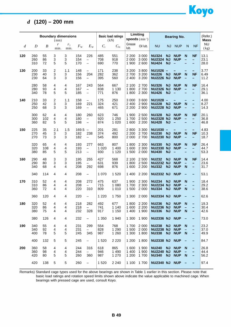
B 49
d (120) – 200 mm
Boundary dimensions(mm)
Basic load ratings(kN)
Limitingspeeds (min–1)
Bearing No. (Refer.)Mass
d D Br
min.r1
min.FW EW Cr C0r NU NJ NUP N NF NU
(kg)Greaselub. Oil lub.
120
130
140
150
160
170
180
190
200
NU324 NJ NUP N NFNU2324 NJ NUP – –NU424 NJ – – –
NU1026 – – – –NU226 NJ NUP N NFNU2226 NJ NUP – –
NU326 NJ NUP N NFNU2326 NJ NUP – –NU426 NJ – – –
NU1028 – – – –NU228 NJ NUP N –NU2228 NJ NUP – –
NU328 NJ NUP N NFNU2328 NJ NUP – –NU428 NJ – – –
NU1030 – – – –NU230 NJ NUP N NFNU2230 NJ NUP – –
NU330 NJ NUP N NFNU2330 NJ NUP – –NU430 NJ – – –
NU232 NJ NUP N NFNU2232 NJ NUP – –NU332 NJ NUP N –
NU2332 NJ NUP – –
NU234 NJ NUP N –NU2234 NJ NUP – –NU334 NJ NUP N –
NU2334 NJ NUP – –
NU236 NJ NUP N –NU2236 NJ NUP – –NU336 NJ NUP N –
NU2336 NJ NUP – –
NU238 NJ NUP N –NU2238 NJ NUP – –NU338 NJ NUP N –
NU2338 NJ NUP – –
NU240 NJ NUP N –NU2240 NJ NUP – –NU340 NJ NUP N –
NU2340 NJ NUP – –
260 55 3 3 154 226 485 551 2 200 3 000260 86 3 3 154 – 708 918 2 000 3 000310 72 5 5 170 – 690 770 1 900 2 600
200 33 2 1.1 148 – 171 238 3 200 3 800230 40 3 3 156 204 282 362 2 700 3 200230 64 3 3 156 – 395 560 2 400 3 200
280 58 4 4 167 243 564 667 2 100 2 700280 93 4 4 167 – 838 1 130 1 800 2 700340 78 5 5 185 – 771 876 1 800 2 300
210 33 2 1.1 158 – 175 250 3 000 3 600250 42 3 3 169 221 324 421 2 400 2 900250 68 3 3 169 – 465 671 2 200 2 900
300 62 4 4 180 260 623 746 1 900 2 500300 102 4 4 180 – 920 1 250 1 700 2 500360 82 5 5 198 – 874 1 020 1 600 2 200
225 35 2.1 1.5 169.5 – 201 281 2 800 3 300270 45 3 3 182 238 374 492 2 200 2 700270 73 3 3 182 – 545 800 2 000 2 700
320 65 4 4 193 277 663 807 1 800 2 300320 108 4 4 193 – 1 020 1 400 1 600 2 300380 85 5 5 213 – 930 1 120 1 500 2 000
290 48 3 3 195 255 427 568 2 100 2 500290 80 3 3 195 – 631 939 1 800 2 500340 68 4 4 208 292 698 876 1 600 2 200
340 114 4 4 208 – 1 070 1 520 1 400 2 200
310 52 4 4 208 272 475 637 1 900 2 300310 86 4 4 208 – 715 1 080 1 700 2 300360 72 4 4 220 310 809 1 010 1 500 2 000
360 120 4 4 220 – 1 220 1 750 1 300 2 000
320 52 4 4 218 282 492 677 1 800 2 200320 86 4 4 218 – 741 1 140 1 600 2 200380 75 4 4 232 328 917 1 150 1 400 1 900
380 126 4 4 232 – 1 350 1 940 1 300 1 900
340 55 4 4 231 299 554 768 1 700 2 000340 92 4 4 231 – 828 1 290 1 500 2 000400 78 5 5 245 345 987 1 260 1 300 1 800
400 132 5 5 245 – 1 520 2 220 1 200 1 800
360 58 4 4 244 316 618 865 1 600 1 900360 98 4 4 244 – 946 1 490 1 400 1 900420 80 5 5 260 360 987 1 270 1 200 1 700
420 138 5 5 260 – 1 520 2 240 1 100 1 700
13.123.128.0
3.776.4911.2
16.429.136.1
4.008.2714.3
20.136.846.8
4.8310.318.7
26.444.753.3
14.423.631.7
53.1
18.429.238.6
62.6
19.330.442.6
73.0
23.237.049.9
84.7
26.844.456.2
97.4
Remarks) Standard cage types used for the above bearings are shown in Table 1 earlier in this section. Please note thatbasic load ratings and rotation speed limits shown above indicate the value applicable to machined cage. Whenbearings with pressed cage are used, consult Koyo.
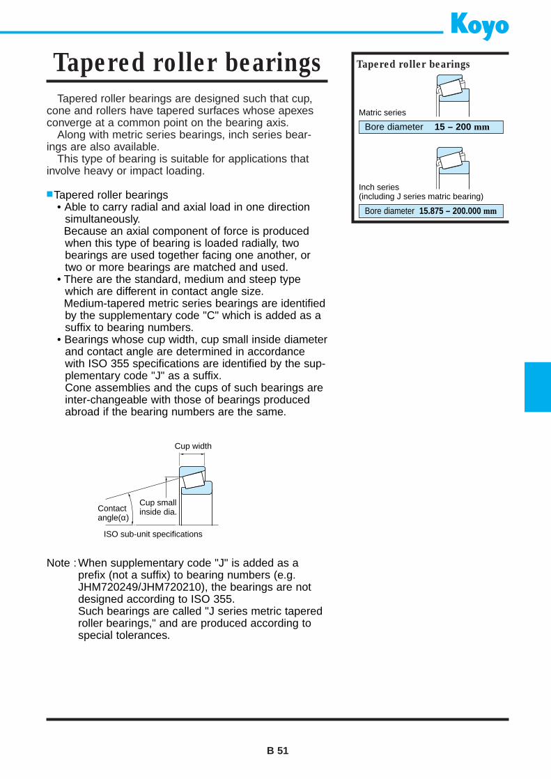
Tapered roller bearings are designed such that cup,cone and rollers have tapered surfaces whose apexesconverge at a common point on the bearing axis.
Along with metric series bearings, inch series bear-ings are also available.
This type of bearing is suitable for applications thatinvolve heavy or impact loading.
Tapered roller bearings• Able to carry radial and axial load in one direction
simultaneously.Because an axial component of force is producedwhen this type of bearing is loaded radially, twobearings are used together facing one another, ortwo or more bearings are matched and used.
• There are the standard, medium and steep typewhich are different in contact angle size.Medium-tapered metric series bearings are identifiedby the supplementary code "C" which is added as asuffix to bearing numbers.
• Bearings whose cup width, cup small inside diameterand contact angle are determined in accordancewith ISO 355 specifications are identified by the sup-plementary code "J" as a suffix.Cone assemblies and the cups of such bearings areinter-changeable with those of bearings producedabroad if the bearing numbers are the same.
B 51
Tapered roller bearings Tapered roller bearings
Bore diameter 15 – 200 mm
Bore diameter 15.875 – 200.000 mm
Note : When supplementary code "J" is added as a prefix (not a suffix) to bearing numbers (e.g.JHM720249/JHM720210), the bearings are notdesigned according to ISO 355.Such bearings are called "J series metric taperedroller bearings," and are produced according tospecial tolerances.
Contactangle(α)
Cup smallinside dia.
Cup width
ISO sub-unit specifications
Matric series
Inch series(including J series matric bearing)
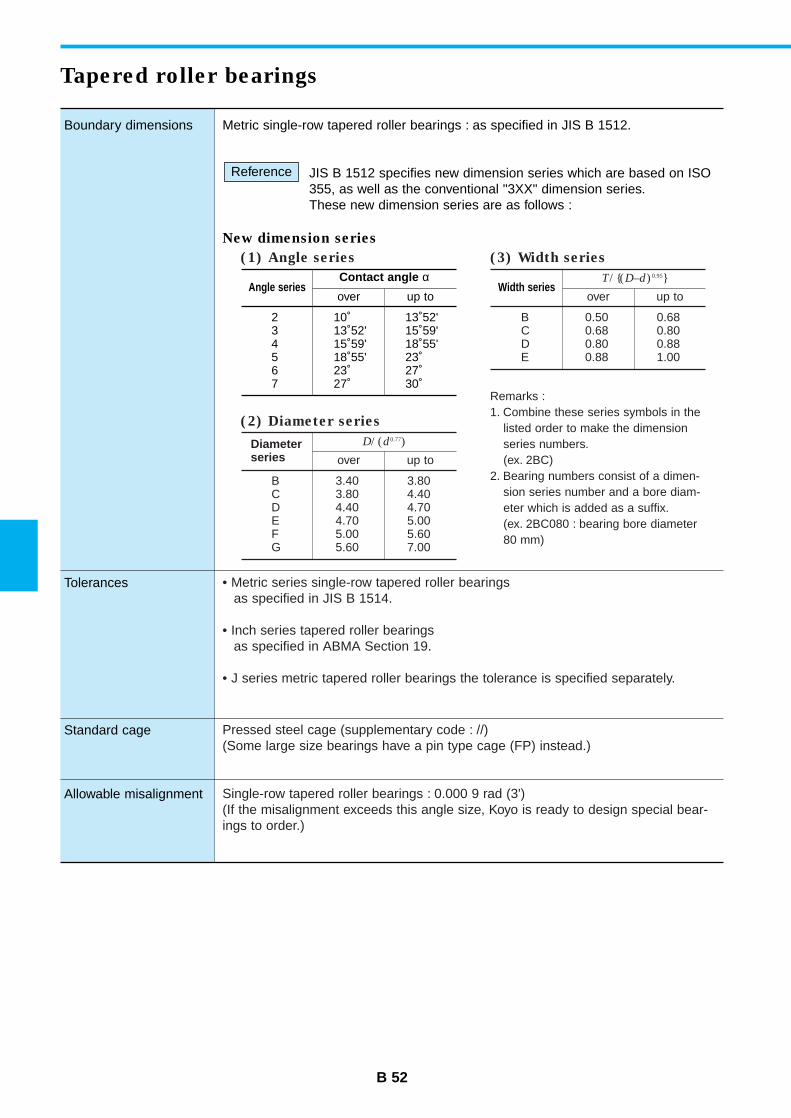
B 52
Boundary dimensions
Tolerances
Standard cage
Allowable misalignment
Metric single-row tapered roller bearings : as specified in JIS B 1512.
JIS B 1512 specifies new dimension series which are based on ISO355, as well as the conventional "3XX" dimension series.These new dimension series are as follows :
New dimension series
Reference
Tapered roller bearings
Angle seriesContact angle α
over up to
2 10˚ 13˚52'3 13˚52' 15˚59'4 15˚59' 18˚55'5 18˚55' 23˚6 23˚ 27˚7 27˚ 30˚
Width seriesT/ (D–d)0.95
over up to
B 0.50 0.68C 0.68 0.80D 0.80 0.88E 0.88 1.00
Diameterseries
D/ (d0.77)
over up to
B 3.40 3.80C 3.80 4.40D 4.40 4.70E 4.70 5.00F 5.00 5.60G 5.60 7.00
(2) Diameter series
(1) Angle series (3) Width series
Remarks :1. Combine these series symbols in the
listed order to make the dimensionseries numbers.(ex. 2BC)
2. Bearing numbers consist of a dimen-sion series number and a bore diam-eter which is added as a suffix.(ex. 2BC080 : bearing bore diameter80 mm)
• Metric series single-row tapered roller bearingsas specified in JIS B 1514.
• Inch series tapered roller bearingsas specified in ABMA Section 19.
• J series metric tapered roller bearings the tolerance is specified separately.
Pressed steel cage (supplementary code : //)(Some large size bearings have a pin type cage (FP) instead.)
Single-row tapered roller bearings : 0.000 9 rad (3')(If the misalignment exceeds this angle size, Koyo is ready to design special bear-ings to order.)
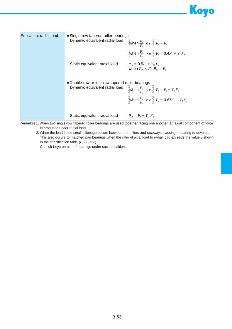
B 53
Equivalent radial load Single-row tapered roller bearingsDynamic equivalent radial load
Static equivalent radial load P0r = 0.5Fr + Y0 Fa
when P0r < Fr, P0r = Fr
Double-row or four-row tapered roller bearingsDynamic equivalent radial load
Static equivalent radial load P0r = Fr + Y0 Fa
when ≤ e Pr = Fr
when > e Pr = 0.4Fr + Y1 FaFa
Fr
Fa
Fr
when ≤ e Pr = Fr + Y2 Fa
when > e Pr = 0.67Fr + Y3 FaFa
Fr
Fa
Fr
Remarks) 1. When two single-row tapered roller bearings are used together facing one another, an axial component of forceis produced under radial load.
2. When the load is too small, slippage occurs between the rollers and raceways, causing smearing to develop.This also occurs to matched pair bearings when the ratio of axial load to radial load exceeds the value e shownin the specification table (Fa / Fr > e).Consult Koyo on use of bearings under such conditions.
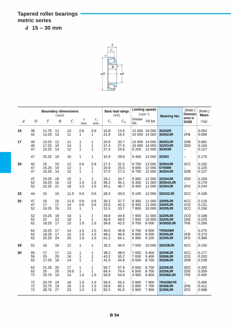
B 54
d 15 – 30 mm
Tapered roller bearingsmetric series
Boundary dimensions(mm)
Basic load ratings(kN)
Limiting speeds(min–1) Bearing No.
(Refer.)Mass
d D T B Cr
min.r1
min.Cr C0r (kg)Grease
lub. Oil lub.
15
17
20
22
25
28
30
30202R30302JR
30203JR32203JR30303R
32303
32004JR57008R30204JR
32204JR30304AJR32304JR
320/22JR
32005JR33005JR30205JR
32205JR33205JR30305DJR
TR0506R30305JR32305JR
320/28JR
32006JR33006JR30206JR
32206JR33206JR30306DJR
TRA0607R30306JR32306JR
35 11.75 11 10 0.6 0.6 15.8 14.5 12 000 16 00042 14.25 13 11 1 1 21.9 19.2 10 000 14 000
40 13.25 12 11 1 1 20.8 20.7 10 000 14 00040 17.25 16 14 1 1 27.4 27.5 10 000 14 00047 15.25 14 12 1 1 27.4 24.5 9 200 12 000
47 20.25 19 16 1 1 31.9 29.9 9 400 13 000
42 15 15 12 0.6 0.6 27.3 31.5 9 700 13 00047 15.25 14 12 1 1 25.8 25.5 9 000 12 00047 15.25 14 12 1 1 27.0 27.2 8 700 12 000
47 19.25 18 15 1 1 33.1 34.7 8 900 12 00052 16.25 16 13 1.5 1.5 36.2 35.1 8 300 11 00052 22.25 21 18 1.5 1.5 45.1 46.7 8 400 11 000
44 15 15 11.5 0.6 0.6 28.3 33.6 9 100 12 000
47 15 15 11.5 0.6 0.6 30.2 37.7 8 300 11 00047 17 17 14 0.6 0.6 33.5 42.3 8 300 11 00052 16.25 15 13 1 1 31.5 33.7 7 800 10 000
52 19.25 18 16 1 1 39.8 44.8 7 900 11 00052 22 22 18 1 1 48.9 58.5 7 900 10 00062 18.25 17 13 1.5 1.5 39.8 42.5 5 700 8 000
62 18.25 17 14 1.5 1.5 45.0 45.8 6 700 9 00062 18.25 17 15 1.5 1.5 48.2 46.9 6 800 9 00062 25.25 24 20 1.5 1.5 61.2 64.1 6 900 9 100
52 16 16 12 1 1 35.2 44.0 7 500 10 000
55 17 17 13 1 1 38.2 48.0 7 000 9 40055 20 20 16 1 1 43.2 55.2 7 000 9 40062 17.25 16 14 1 1 41.5 44.8 6 500 8 700
62 21.25 20 17 1 1 50.7 57.9 6 500 8 70062 25 25 19.5 1 1 66.4 79.4 6 500 8 70072 20.75 19 14 1.5 1.5 50.9 54.9 4 900 6 800
72 20.75 19 16 1.5 1.5 56.5 55.2 5 900 7 90072 20.75 19 16 1.5 1.5 59.6 60.1 5 800 7 70072 28.75 27 23 1.5 1.5 82.2 91.6 5 900 7 900
(Refer.)Dimensionseries toISO355
– 0.0542FB 0.098
2DB 0.0812DD 0.104– 0.127
– 0.170
3CC 0.102– 0.1252DB 0.127
2DD 0.159– 0.1792FD 0.244
3CC 0.108
4CC 0.1182CE 0.1313CC 0.156
2CD 0.1882DE 0.2257FB 0.269
– 0.2752FB 0.2732FD 0.386
4CC 0.150
4CC 0.1772CE 0.2033DB 0.236
3DC 0.2922DE 0.3597FB 0.400
– 0.4052FB 0.4112FD 0.588
r
r1
ød
C
B
T
øD
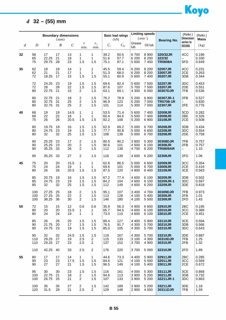
B 55
d 32 – (55) mm
Boundary dimensions(mm)
Basic load ratings(kN)
Limiting speeds(min–1) Bearing No.
(Refer.)Mass
d D T B Cr
min.r1
min.Cr C0r (kg)Grease
lub. Oil lub.
32
35
40
45
50
55
320/32JR322/32TR0608A
32007JR33007JR30207JR
32207JR33207JR30307DJR
30307JR-1TR0708-1R32307JR
32008JR33008JR33108JR
30208JR32208JR33208JR
30308DJR30308JRTR0809AR
32308JR
32009JR33009JR33109JR
30209JR32209JR-133209JR
30309DJR30309JR32309JR
32910JR32010JR33010JR
33110JR30210JR32210JR
33210JR30310DJR30310JR
32310JR
32911JR32011JR33011JR
33111JR30211JR32211JR-1
33211JR30311DJR
58 17 17 13 1 1 39.2 50.6 6 700 8 90065 22.25 21 18 1 1 51.6 57.7 6 200 8 20075 29.75 28 23 1.5 1.5 75.1 87.1 5 600 7 400
62 18 18 14 1 1 45.5 59.4 6 200 8 20062 21 21 17 1 1 51.3 68.0 6 200 8 20072 18.25 17 15 1.5 1.5 55.1 60.9 5 600 7 400
72 24.25 23 19 1.5 1.5 69.6 82.4 5 600 7 50072 28 28 22 1.5 1.5 87.6 107 5 700 7 50080 22.75 21 15 2 1.5 63.1 69.1 4 300 6 000
80 22.75 21 18 2 1.5 76.2 78.9 5 200 6 90080 32.75 31 25 2 1.5 96.9 123 5 200 7 00080 32.75 31 25 2 1.5 101 114 5 300 7 000
68 19 19 14.5 1 1 53.5 71.4 5 600 7 40068 22 22 18 1 1 60.4 84.6 5 500 7 40075 26 26 20.5 1.5 1.5 82.2 108 5 200 6 900
80 19.75 18 16 1.5 1.5 62.9 69.2 5 000 6 70080 24.75 23 19 1.5 1.5 77.7 90.8 5 000 6 60080 32 32 25 1.5 1.5 108 139 5 000 6 700
90 25.25 23 17 2 1.5 80.5 90.2 3 800 5 30090 25.25 23 20 2 1.5 90.6 101 4 500 6 10090 35.25 33 26 2 1.5 112 138 4 700 6 200
90 35.25 33 27 2 1.5 116 139 4 600 6 200
75 20 20 15.5 1 1 62.8 86.5 5 000 6 60075 24 24 19 1 1 69.6 101 5 000 6 70080 26 26 20.5 1.5 1.5 87.5 120 4 800 6 400
85 20.75 19 16 1.5 1.5 67.2 77.4 4 600 6 10085 24.75 23 19 1.5 1.5 84.2 104 4 600 6 10085 32 32 25 1.5 1.5 112 149 4 600 6 200
100 27.25 25 18 2 1.5 95.1 107 3 400 4 700100 27.25 25 22 2 1.5 113 128 4 100 5 400100 38.25 36 30 2 1.5 146 180 4 100 5 500
72 15 15 12 0.6 0.6 35.9 56.3 4 900 6 60080 20 20 15.5 1 1 65.7 94.5 4 600 6 10080 24 24 19 1 1 73.0 110 4 600 6 100
85 26 26 20 1.5 1.5 89.4 127 4 400 5 90090 21.75 20 17 1.5 1.5 76.5 91.7 4 300 5 70090 24.75 23 19 1.5 1.5 85.0 105 4 300 5 700
90 32 32 24.5 1.5 1.5 119 167 4 300 5 700110 29.25 27 19 2.5 2 115 133 3 100 4 300110 29.25 27 23 2.5 2 137 152 3 700 4 900
110 42.25 40 33 2.5 2 176 220 3 700 5 000
80 17 17 14 1 1 44.6 73.3 4 400 5 90090 23 23 17.5 1.5 1.5 84.6 121 4 100 5 50090 27 27 21 1.5 1.5 96.5 149 4 100 5 400
95 30 30 23 1.5 1.5 116 161 4 000 5 300100 22.75 21 18 2 1.5 94.6 113 3 900 5 200100 26.75 25 21 2 1.5 107 133 3 900 5 200
100 35 35 27 2 1.5 142 189 3 900 5 200120 31.5 29 21 2.5 2 129 148 2 900 4 000
(Refer.)Dimensionseries toISO355
4CC 0.196– 0.3305FD 0.649
4CC 0.2312CE 0.2633DB 0.344
3DC 0.4532DE 0.5517FB 0.536
2FB 0.527– 0.8302FE 0.776
3CD 0.2822BE 0.3262CE 0.508
3DB 0.4343DC 0.5542DE 0.758
7FB 0.7572FB 0.757– 1.10
2FD 1.06
3CC 0.3542CE 0.4163CE 0.563
3DB 0.5023DC 0.5973DE 0.818
7FB 0.9732FB 1.012FD 1.43
2BC 0.1953CC 0.3892CE 0.451
3CE 0.5943DB 0.5663DC 0.643
3DE 0.8877FB 1.252FB 1.32
2FD 1.89
2BC 0.2853CC 0.5692CE 0.672
3CE 0.8683DB 0.7323DC 0.863
3DE 1.187FB 1.59
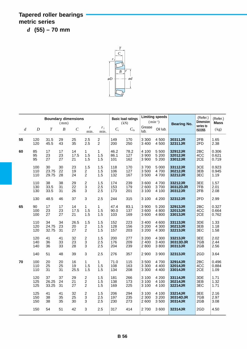
B 56
d (55) – 70 mm
Tapered roller bearingsmetric series
Boundary dimensions(mm)
Basic load ratings(kN)
Limiting speeds(min–1) Bearing No.
(Refer.)Mass
d D T B Cr
min.r1
min.Cr C0r (kg)Grease
lub. Oil lub.
55
60
65
70
30311JR32311JR
32912JR32012JR33012JR
33112JR30212JR32212JR
33212JR30312DJR30312JR
32312JR
32913JR32013JR33013JR
33113JR30213JR32213JR
33213JR30313DJR30313JR
32313JR
32914JR32014JR33014JR
33114JR30214JR32214JR
33214JR30314DJR30314JR
32314JR
120 31.5 29 25 2.5 2 149 170 3 300 4 500120 45.5 43 35 2.5 2 200 250 3 400 4 500
85 17 17 14 1 1 46.2 78.2 4 100 5 50095 23 23 17.5 1.5 1.5 86.1 127 3 900 5 20095 27 27 21 1.5 1.5 101 162 3 900 5 200
100 30 30 23 1.5 1.5 118 170 3 700 5 000110 23.75 22 19 2 1.5 106 127 3 500 4 700110 29.75 28 24 2 1.5 132 167 3 500 4 700
110 38 38 29 2 1.5 174 239 3 600 4 700130 33.5 31 22 3 2.5 153 179 2 600 3 700130 33.5 31 26 3 2.5 173 201 3 100 4 100
130 48.5 46 37 3 2.5 244 315 3 100 4 200
90 17 17 14 1 1 47.4 83.1 3 900 5 200100 23 23 17.5 1.5 1.5 90.0 137 3 600 4 800100 27 27 21 1.5 1.5 103 169 3 600 4 800
110 34 34 26.5 1.5 1.5 152 223 3 400 4 600120 24.75 23 20 2 1.5 128 156 3 200 4 300120 32.75 31 27 2 1.5 157 203 3 200 4 300
120 41 41 32 2 1.5 200 277 3 200 4 300140 36 33 23 3 2.5 176 209 2 400 3 400140 36 33 28 3 2.5 204 239 2 800 3 800
140 51 48 39 3 2.5 276 357 2 900 3 900
100 20 20 16 1 1 71.0 115 3 500 4 700110 25 25 19 1.5 1.5 108 163 3 300 4 400110 31 31 25.5 1.5 1.5 134 208 3 300 4 400
120 37 37 29 2 1.5 181 266 3 100 4 200125 26.25 24 21 2 1.5 138 173 3 100 4 100125 33.25 31 27 2 1.5 169 225 3 100 4 100
125 41 41 32 2 1.5 206 294 3 100 4 100150 38 35 25 3 2.5 197 235 2 300 3 200150 38 35 30 3 2.5 230 273 2 600 3 500
150 54 51 42 3 2.5 317 414 2 700 3 600
(Refer.)Dimensionseries toISO355
2FB 1.652FD 2.38
2BC 0.3064CC 0.6212CE 0.719
3CE 0.9233EB 0.9453EC 1.19
3EE 1.577FB 2.012FB 2.08
2FD 2.99
2BC 0.3274CC 0.6642CE 0.762
3DE 1.333EB 1.183EC 1.58
3EE 2.027GB 2.442GB 2.56
2GD 3.64
2BC 0.4964CC 0.8842CE 1.09
3DE 1.713EB 1.323EC 1.71
3EE 2.167GB 2.972GB 3.08
2GD 4.50
r
r1
ød
C
B
T
øD
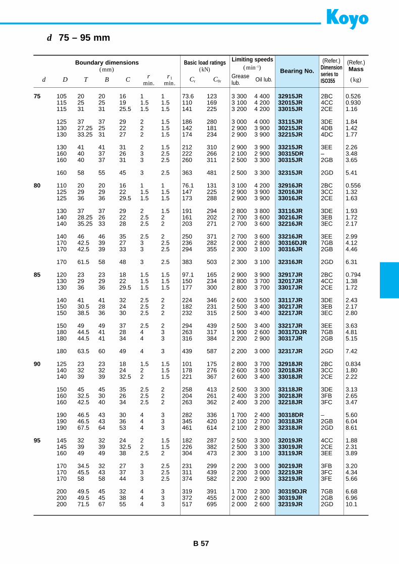
B 57
d 75 – 95 mm
Boundary dimensions(mm)
Basic load ratings(kN)
Limiting speeds(min–1) Bearing No.
(Refer.)Mass
d D T B Cr
min.r1
min.Cr C0r (kg)Grease
lub. Oil lub.
75
80
85
90
95
32915JR32015JR33015JR
33115JR30215JR32215JR
33215JR30315DR30315JR
32315JR
32916JR32016JR33016JR
33116JR30216JR32216JR
33216JR30316DJR30316JR
32316JR
32917JR32017JR33017JR
33117JR30217JR32217JR
33217JR30317DJR30317JR
32317JR
32918JR32018JR33018JR
33118JR30218JR32218JR
30318DR30318JR32318JR
32019JR33019JR33119JR
30219JR32219JR33219JR
30319DJR30319JR32319JR
105 20 20 16 1 1 73.6 123 3 300 4 400115 25 25 19 1.5 1.5 110 169 3 100 4 200115 31 31 25.5 1.5 1.5 141 225 3 200 4 200
125 37 37 29 2 1.5 186 280 3 000 4 000130 27.25 25 22 2 1.5 142 181 2 900 3 900130 33.25 31 27 2 1.5 174 234 2 900 3 900
130 41 41 31 2 1.5 212 310 2 900 3 900160 40 37 26 3 2.5 222 266 2 100 2 900160 40 37 31 3 2.5 260 311 2 500 3 300
160 58 55 45 3 2.5 363 481 2 500 3 300
110 20 20 16 1 1 76.1 131 3 100 4 200125 29 29 22 1.5 1.5 147 225 2 900 3 900125 36 36 29.5 1.5 1.5 173 288 2 900 3 900
130 37 37 29 2 1.5 191 294 2 800 3 800140 28.25 26 22 2.5 2 161 202 2 700 3 600140 35.25 33 28 2.5 2 203 271 2 700 3 600
140 46 46 35 2.5 2 250 371 2 700 3 600170 42.5 39 27 3 2.5 236 282 2 000 2 800170 42.5 39 33 3 2.5 294 355 2 300 3 100
170 61.5 58 48 3 2.5 383 503 2 300 3 100
120 23 23 18 1.5 1.5 97.1 165 2 900 3 900130 29 29 22 1.5 1.5 150 234 2 800 3 700130 36 36 29.5 1.5 1.5 177 300 2 800 3 700
140 41 41 32 2.5 2 224 346 2 600 3 500150 30.5 28 24 2.5 2 182 231 2 500 3 400150 38.5 36 30 2.5 2 232 315 2 500 3 400
150 49 49 37 2.5 2 294 439 2 500 3 400180 44.5 41 28 4 3 263 317 1 900 2 600180 44.5 41 34 4 3 316 384 2 200 2 900
180 63.5 60 49 4 3 439 587 2 200 3 000
125 23 23 18 1.5 1.5 101 175 2 800 3 700140 32 32 24 2 1.5 178 276 2 600 3 500140 39 39 32.5 2 1.5 221 367 2 600 3 400
150 45 45 35 2.5 2 258 413 2 500 3 300160 32.5 30 26 2.5 2 204 261 2 400 3 200160 42.5 40 34 2.5 2 263 362 2 400 3 200
190 46.5 43 30 4 3 282 336 1 700 2 400190 46.5 43 36 4 3 345 420 2 100 2 700190 67.5 64 53 4 3 461 614 2 100 2 800
145 32 32 24 2 1.5 182 287 2 500 3 300145 39 39 32.5 2 1.5 226 382 2 500 3 300160 49 49 38 2.5 2 304 473 2 300 3 100
170 34.5 32 27 3 2.5 231 299 2 200 3 000170 45.5 43 37 3 2.5 311 439 2 200 3 000170 58 58 44 3 2.5 374 582 2 200 2 900
200 49.5 45 32 4 3 319 391 1 700 2 300200 49.5 45 38 4 3 372 455 2 000 2 600200 71.5 67 55 4 3 517 695 2 000 2 600
(Refer.)Dimensionseries toISO355
2BC 0.5264CC 0.9302CE 1.16
3DE 1.844DB 1.424DC 1.77
3EE 2.26– 3.482GB 3.65
2GD 5.41
2BC 0.5563CC 1.322CE 1.63
3DE 1.933EB 1.723EC 2.17
3EE 2.997GB 4.122GB 4.46
2GD 6.31
2BC 0.7944CC 1.382CE 1.72
3DE 2.433EB 2.173EC 2.80
3EE 3.637GB 4.812GB 5.15
2GD 7.42
2BC 0.8343CC 1.802CE 2.22
3DE 3.133FB 2.653FC 3.47
– 5.602GB 6.042GD 8.61
4CC 1.882CE 2.313EE 3.89
3FB 3.203FC 4.343FE 5.66
7GB 6.682GB 6.962GD 10.1
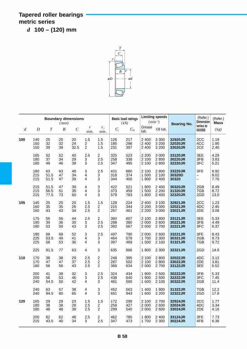
B 58
d 100 – (120) mm
Tapered roller bearingsmetric series
Boundary dimensions(mm)
Basic load ratings(kN)
Limiting speeds(min–1) Bearing No.
(Refer.)Mass
d D T B Cr
min.r1
min.Cr C0r (kg)Grease
lub. Oil lub.
100
105
110
120
32920JR32020JR33020JR
33120JR30220JR32220JR
33220JR30320D30320
30320JR31320JR32320JR
32921JR32021JR33021JR
33121JR30221JR32221JR
33221JR30321JR31321JR
32321JR
32022JR33022JR33122JR
30222JR32222JR30322JR
31322JR32322JR
32924JR32024JR33024JR
33124JR30224JR
140 25 25 20 1.5 1.5 126 217 2 400 3 300150 32 32 24 2 1.5 185 298 2 400 3 200150 39 39 32.5 2 1.5 231 397 2 400 3 200
165 52 52 40 2.5 2 325 523 2 200 3 000180 37 34 29 3 2.5 258 338 2 100 2 800180 49 46 39 3 2.5 347 495 2 100 2 800
180 63 63 48 3 2.5 431 680 2 100 2 800215 51.5 47 34 4 3 318 374 1 500 2 100215 51.5 47 39 4 3 344 400 1 800 2 400
215 51.5 47 39 4 3 422 521 1 800 2 400215 56.5 51 35 4 3 373 459 1 500 2 200215 77.5 73 60 4 3 579 783 1 800 2 400
145 25 25 20 1.5 1.5 128 224 2 400 3 100160 35 35 26 2.5 2 215 344 2 200 3 000160 43 43 34 2.5 2 267 461 2 200 3 000
175 56 56 44 2.5 2 360 607 2 100 2 800190 39 36 30 3 2.5 288 380 2 000 2 600190 53 50 43 3 2.5 392 567 2 000 2 700
190 68 68 52 3 2.5 497 790 2 000 2 600225 53.5 49 41 4 3 464 578 1 700 2 300225 58 53 36 4 3 397 489 1 500 2 100
225 81.5 77 63 4 3 635 866 1 800 2 300
170 38 38 29 2.5 2 248 395 2 100 2 800170 47 47 37 2.5 2 287 502 2 100 2 800180 56 56 43 2.5 2 369 634 2 000 2 700
200 41 38 32 3 2.5 324 434 1 900 2 500200 56 53 46 3 2.5 438 640 1 900 2 500240 54.5 50 42 4 3 481 590 1 600 2 100
240 63 57 38 4 3 452 563 1 400 1 900240 84.5 80 65 4 3 691 943 1 600 2 200
165 29 29 23 1.5 1.5 172 298 2 100 2 700180 38 38 29 2.5 2 258 427 2 000 2 600180 48 48 38 2.5 2 299 540 2 000 2 600
200 62 62 48 2.5 2 462 785 1 800 2 400215 43.5 40 34 3 2.5 347 473 1 700 2 300
(Refer.)Dimensionseries toISO355
2CC 1.194CC 1.952CE 2.40
3EE 4.293FB 3.833FC 5.21
3FE 6.92– 8.02– 7.76
2GB 8.497GB 8.722GD 13.0
2CC 1.234DC 2.452DE 3.08
3EE 5.333FB 4.493FC 6.37
3FE 8.432GB 9.737GB 9.72
2GD 14.9
4DC 3.122DE 3.813EE 5.52
3FB 5.333FC 7.452GB 11.4
7GB 12.22GD 17.8
2CC 1.774DC 3.342DE 4.16
3FE 7.734FB 6.36
r
r1
ød
C
B
T
øD
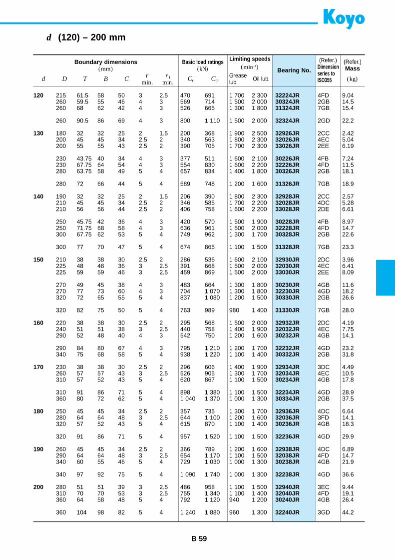
B 59
d (120) – 200 mm
Boundary dimensions(mm)
Basic load ratings(kN)
Limiting speeds(min–1) Bearing No.
(Refer.)Mass
d D T B Cr
min.r1
min.Cr C0r (kg)Grease
lub. Oil lub.
120
130
140
150
160
170
180
190
200
32224JR30324JR31324JR
32324JR
32926JR32026JR33026JR
30226JR32226JR30326JR
31326JR
32928JR32028JR33028JR
30228JR32228JR30328JR
31328JR
32930JR32030JR33030JR
30230JR32230JR30330JR
31330JR
32932JR32032JR30232JR
32232JR30332JR
32934JR32034JR30234JR
32234JR30334JR
32936JR32036JR30236JR
32236JR
32938JR32038JR30238JR
32238JR
32940JR32040JR30240JR
32240JR
215 61.5 58 50 3 2.5 470 691 1 700 2 300260 59.5 55 46 4 3 569 714 1 500 2 000260 68 62 42 4 3 526 665 1 300 1 800
260 90.5 86 69 4 3 800 1 110 1 500 2 000
180 32 32 25 2 1.5 200 368 1 900 2 500200 45 45 34 2.5 2 340 563 1 800 2 300200 55 55 43 2.5 2 390 705 1 700 2 300
230 43.75 40 34 4 3 377 511 1 600 2 100230 67.75 64 54 4 3 554 830 1 600 2 200280 63.75 58 49 5 4 657 834 1 400 1 800
280 72 66 44 5 4 589 748 1 200 1 600
190 32 32 25 2 1.5 206 390 1 800 2 300210 45 45 34 2.5 2 346 585 1 700 2 200210 56 56 44 2.5 2 406 758 1 600 2 200
250 45.75 42 36 4 3 420 570 1 500 1 900250 71.75 68 58 4 3 636 961 1 500 2 000300 67.75 62 53 5 4 749 962 1 300 1 700
300 77 70 47 5 4 674 865 1 100 1 500
210 38 38 30 2.5 2 286 536 1 600 2 100225 48 48 36 3 2.5 391 668 1 500 2 000225 59 59 46 3 2.5 459 869 1 500 2 000
270 49 45 38 4 3 483 664 1 300 1 800270 77 73 60 4 3 704 1 070 1 300 1 800320 72 65 55 5 4 837 1 080 1 200 1 500
320 82 75 50 5 4 763 989 980 1 400
220 38 38 30 2.5 2 295 568 1 500 2 000240 51 51 38 3 2.5 440 758 1 400 1 900290 52 48 40 4 3 542 750 1 200 1 600
290 84 80 67 4 3 795 1 210 1 200 1 700340 75 68 58 5 4 938 1 220 1 100 1 400
230 38 38 30 2.5 2 296 606 1 400 1 900260 57 57 43 3 2.5 526 905 1 300 1 700310 57 52 43 5 4 620 867 1 100 1 500
310 91 86 71 5 4 898 1 380 1 100 1 500360 80 72 62 5 4 1 040 1 370 1 000 1 300
250 45 45 34 2.5 2 357 735 1 300 1 700280 64 64 48 3 2.5 644 1 100 1 200 1 600320 57 52 43 5 4 615 870 1 100 1 400
320 91 86 71 5 4 957 1 520 1 100 1 500
260 45 45 34 2.5 2 366 789 1 200 1 600290 64 64 48 3 2.5 654 1 170 1 100 1 500340 60 55 46 5 4 729 1 030 1 000 1 300
340 97 92 75 5 4 1 090 1 740 1 000 1 300
280 51 51 39 3 2.5 486 958 1 100 1 500310 70 70 53 3 2.5 755 1 340 1 100 1 400360 64 58 48 5 4 792 1 120 940 1 200
360 104 98 82 5 4 1 240 1 880 960 1 300
(Refer.)Dimensionseries toISO355
4FD 9.042GB 14.57GB 15.4
2GD 22.2
2CC 2.424EC 5.042EE 6.19
4FB 7.244FD 11.52GB 18.1
7GB 18.9
2CC 2.574DC 5.282DE 6.61
4FB 8.974FD 14.72GB 22.6
7GB 23.3
2DC 3.964EC 6.412EE 8.09
4GB 11.64GD 18.22GB 26.6
7GB 28.0
2DC 4.194EC 7.754GB 14.1
4GD 23.22GB 31.8
3DC 4.494EC 10.54GB 17.8
4GD 28.92GB 37.5
4DC 6.643FD 14.14GB 18.3
4GD 29.9
4DC 6.894FD 14.74GB 21.9
4GD 36.6
3EC 9.444FD 19.14GB 26.4
3GD 44.2
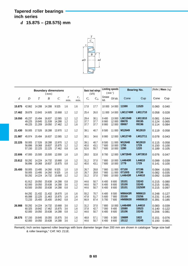
11590 11520
LM11749R LM11710
LM11949 LM1191009078 0919509067 09196
M12649 M12610
LM12749 LM12711
M12648 M126101755 17291280 1220
LM72849 LM72810
L44640R L446101779 1729
07100 0719607100S 07196L44643R L44610
15101 1524315100 1524515101 15250R
M86643R M8661023100 23256HM88630 HM88610
L44649R L4461015580 1552315106 15245
1988R 192215112 15245
Bearing No.
Cone Cup
B 60
d 15.875 – (28.575) mm
Tapered roller bearingsinch series
Boundary dimensions(mm)
Basic load ratings(kN)
Limiting speeds(min–1)
d D T B Cr
min.r1
min.Cr C0r
Greaselub. Oil lub.
15.875
17.462
19.050
21.430
21.987
22.225
22.606
23.812
25.400
26.988
28.575
42.862 14.288 14.288 9.525 1.6 1.6 17.8 17.7 10 000 14 000
39.878 13.843 14.605 10.668 1.2 1.2 25.4 26.0 11 000 14 000
45.237 15.494 16.637 12.065 1.2 1.2 29.4 30.1 9 400 13 00049.225 19.845 21.539 14.288 1.2 1.2 37.7 37.7 8 900 12 00049.225 21.209 19.050 17.462 1.2 1.6 37.7 37.7 8 900 12 000
50.005 17.526 18.288 13.970 1.2 1.2 39.1 40.7 8 500 11 000
45.974 15.494 16.637 12.065 1.2 1.2 30.1 34.6 8 900 12 000
50.005 17.526 18.288 13.970 1.2 1.2 39.1 40.7 8 500 11 00056.896 19.368 19.837 15.875 1.2 1.2 40.0 43.1 7 600 10 00057.150 22.225 22.225 17.462 0.8 1.6 52.6 55.7 7 600 10 000
47.000 15.500 15.500 12.000 1.6 1.0 28.0 32.8 8 700 12 000
50.292 14.224 14.732 10.668 1.6 1.2 31.2 37.0 7 800 10 00056.896 19.368 19.837 15.875 0.8 1.2 40.0 43.1 7 600 10 000
50.005 13.495 14.260 9.525 1.0 1.0 26.7 28.8 7 900 11 00050.005 13.495 14.260 9.525 1.6 1.0 26.7 28.8 7 900 11 00050.292 14.224 14.732 10.668 1.2 1.2 31.2 37.0 7 800 10 000
61.912 19.050 20.638 14.288 0.8 2.0 44.6 50.7 6 400 8 60062.000 19.050 20.638 14.288 3.6 1.2 44.6 50.7 6 400 8 60063.500 19.050 20.638 14.288 0.8 1.2 44.6 50.7 6 400 8 600
64.292 21.432 21.432 16.670 1.6 1.6 55.2 70.7 6 400 8 50065.088 22.225 21.463 15.875 1.6 1.6 47.8 51.7 5 600 7 90072.233 25.400 25.400 19.842 0.8 2.4 66.9 87.4 5 700 7 600
50.292 14.224 14.732 10.668 3.6 1.2 31.2 37.0 7 800 10 00060.325 19.842 17.462 15.875 3.6 1.6 37.8 42.7 7 000 9 40062.000 19.050 20.638 14.288 0.8 1.2 44.6 50.7 6 400 8 600
57.150 19.845 19.355 15.875 3.6 1.6 48.8 57.1 7 000 9 30062.000 19.050 20.638 14.288 3.6 1.2 44.6 50.7 6 400 8 600
0.060 0.040
0.058 0.028
0.081 0.0440.124 0.0650.114 0.084
0.119 0.058
0.078 0.043
0.115 0.0580.150 0.1000.189 0.105
0.076 0.047
0.099 0.0390.141 0.100
0.084 0.0350.082 0.0350.092 0.039
0.215 0.0800.215 0.0810.215 0.097
0.248 0.1270.231 0.1400.391 0.185
0.083 0.0390.140 0.1220.206 0.081
0.151 0.0760.193 0.081
(Refer.) Mass (kg)
Cone Cup
Remark) Inch series tapered roller bearings with bore diameter larger than 200 mm are shown in catalogue "large size ball& roller bearings," CAT. NO. 211E.
r
r1
ød
C
B
T
øD
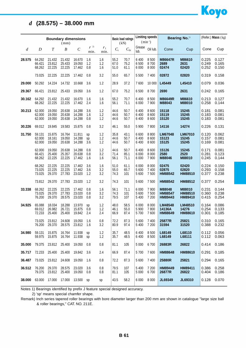
B 61
d (28.575) – 38.000 mm
M86647R M866102689 263102474 02420
02872 02820
L45449 L45410
2690 2631
M86649R M86610M88043 M88010
15118 1524515119 1524515120 15245
14116 14274
LM67048 LM6701015123 1524515125 15245
15126 152452580 2520M88046 M88010
02475 0242002875 02820HM88542 HM88510
HM88542 HM88512
M88048 M88010HM88547 HM88510HM89443 HM89410
LM48548 LM4851014136A 14276HM88649 HM88610
25877R 2582131594 31520
L68149 L68110L68149 L68111
26883R 26822
HM88648 HM88610
25880R 25821
HM89449 HM8941126877R 26822
JL69349 JL69310
Bearing No. 1)
Cone Cup
Boundary dimensions(mm)
Basic load ratings(kN)
Limiting speeds(min–1)
d D T B Cr 2)
min.r1
min.Cr C0r
Greaselub. Oil lub.
28.575
29.000
29.367
30.162
30.213
30.226
31.750
33.338
34.925
34.980
35.000
35.717
36.487
36.512
38.000
64.292 21.432 21.432 16.670 1.6 1.6 55.2 70.7 6 400 8 50066.421 23.812 25.433 19.050 1.2 1.2 67.0 75.2 6 500 8 70068.262 22.225 22.225 17.462 0.8 1.6 51.0 61.1 6 000 8 000
73.025 22.225 22.225 17.462 0.8 3.2 55.0 65.7 5 500 7 400
50.292 14.224 14.732 10.668 3.6 1.2 28.9 37.2 7 600 10 000
66.421 23.812 25.433 19.050 3.6 1.2 67.0 75.2 6 500 8 700
64.292 21.432 21.432 16.670 1.6 1.6 55.2 70.7 6 400 8 50068.262 22.225 22.225 17.462 2.4 1.6 56.1 71.1 6 000 7 900
62.000 19.050 20.638 14.288 3.6 1.2 44.6 50.7 6 400 8 60062.000 19.050 20.638 14.288 1.6 1.2 44.6 50.7 6 400 8 60062.000 19.050 20.638 14.288 0.8 1.2 44.6 50.7 6 400 8 600
69.012 19.845 19.583 15.875 0.8 3.2 46.1 55.0 5 900 7 800
59.131 15.875 16.764 11.811 sp 1.2 35.8 43.1 6 600 8 80062.000 18.161 19.050 14.288 sp 1.2 44.6 50.7 6 400 8 60062.000 19.050 20.638 14.288 3.6 1.2 44.6 50.7 6 400 8 600
62.000 19.050 20.638 14.288 0.8 1.2 44.6 50.7 6 400 8 60066.421 25.400 25.357 20.638 0.8 3.2 71.4 85.1 6 000 8 00068.262 22.225 22.225 17.462 1.6 1.6 56.1 71.1 6 000 7 900
68.262 22.225 22.225 17.462 3.6 1.6 51.0 61.1 6 000 8 00073.025 22.225 22.225 17.462 3.6 3.2 55.0 65.7 5 600 7 40073.025 29.370 27.783 23.020 1.2 3.2 74.3 101 5 600 7 500
73.812 29.370 27.783 23.020 1.2 3.2 74.3 101 5 600 7 500
68.262 22.225 22.225 17.462 0.8 1.6 56.1 71.1 6 000 7 90073.025 29.370 27.783 23.020 0.8 3.2 74.3 101 5 600 7 50076.200 29.370 28.575 23.020 0.8 3.2 79.5 107 5 400 7 200
65.088 18.034 18.288 13.970 sp 1.2 48.0 58.5 6 000 8 00069.012 26.982 26.721 15.875 0.8 1.2 46.1 55.0 5 900 7 80072.233 25.400 25.400 19.842 2.4 2.4 66.9 87.4 5 700 7 600
73.025 23.812 24.608 19.050 1.6 0.8 72.2 87.3 5 600 7 40076.200 29.370 28.575 23.812 1.6 3.2 80.9 97.4 5 400 7 200
59.131 15.875 16.764 11.938 sp 1.2 35.7 48.5 6 400 8 50059.975 15.875 16.764 11.938 sp 1.2 35.7 48.5 6 400 8 500
79.375 23.812 25.400 19.050 0.8 0.8 81.1 105 5 000 6 700
72.233 25.400 25.400 19.842 3.6 2.4 66.9 87.4 5 700 7 600
73.025 23.812 24.608 19.050 1.6 0.8 72.2 87.3 5 600 7 400
76.200 29.370 28.575 23.020 3.6 0.8 79.5 107 5 400 7 20079.375 23.812 25.400 19.050 0.8 0.8 81.1 105 5 000 6 700
63.000 17.000 17.000 13.500 sp sp 43.5 58.2 6 000 8 000
0.225 0.1270.249 0.1650.252 0.150
0.319 0.158
0.079 0.036
0.242 0.165
0.213 0.1270.258 0.144
0.181 0.0810.183 0.0810.183 0.081
0.226 0.131
0.120 0.0620.157 0.0810.169 0.081
0.171 0.0810.281 0.1230.245 0.144
0.224 0.1500.293 0.1580.377 0.238
0.377 0.254
0.231 0.1440.360 0.2380.415 0.254
0.164 0.0860.254 0.1330.301 0.185
0.310 0.1650.388 0.232
0.112 0.0560.112 0.063
0.414 0.186
0.291 0.185
0.294 0.165
0.386 0.2580.404 0.186
0.128 0.070
(Refer.) Mass (kg)
Cone Cup
Notes 1) Bearings identified by prefix J feature special designed accuracy.2) 'sp' means special chamfer shape.
Remark) Inch series tapered roller bearings with bore diameter larger than 200 mm are shown in catalogue "large size ball& roller bearings," CAT. NO. 211E.
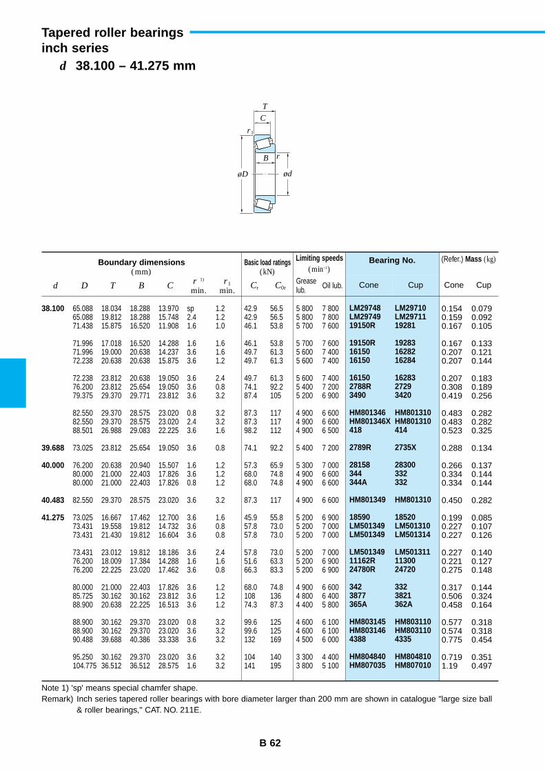
B 62
d 38.100 – 41.275 mm
Tapered roller bearingsinch series
LM29748 LM29710LM29749 LM2971119150R 19281
19150R 1928316150 1628216150 16284
16150 162832788R 27293490 3420
HM801346 HM801310HM801346X HM801310418 414
2789R 2735X
28158 28300344 332344A 332
HM801349 HM801310
18590 18520LM501349 LM501310LM501349 LM501314
LM501349 LM50131111162R 1130024780R 24720
342 3323877 3821365A 362A
HM803145 HM803110HM803146 HM8031104388 4335
HM804840 HM804810HM807035 HM807010
Bearing No.
Cone Cup
Boundary dimensions(mm)
Basic load ratings(kN)
Limiting speeds(min–1)
d D T B Cr 1)
min.r1
min.Cr C0r
Greaselub. Oil lub.
38.100
39.688
40.000
40.483
41.275
65.088 18.034 18.288 13.970 sp 1.2 42.9 56.5 5 800 7 80065.088 19.812 18.288 15.748 2.4 1.2 42.9 56.5 5 800 7 80071.438 15.875 16.520 11.908 1.6 1.0 46.1 53.8 5 700 7 600
71.996 17.018 16.520 14.288 1.6 1.6 46.1 53.8 5 700 7 60071.996 19.000 20.638 14.237 3.6 1.6 49.7 61.3 5 600 7 40072.238 20.638 20.638 15.875 3.6 1.2 49.7 61.3 5 600 7 400
72.238 23.812 20.638 19.050 3.6 2.4 49.7 61.3 5 600 7 40076.200 23.812 25.654 19.050 3.6 0.8 74.1 92.2 5 400 7 20079.375 29.370 29.771 23.812 3.6 3.2 87.4 105 5 200 6 900
82.550 29.370 28.575 23.020 0.8 3.2 87.3 117 4 900 6 60082.550 29.370 28.575 23.020 2.4 3.2 87.3 117 4 900 6 60088.501 26.988 29.083 22.225 3.6 1.6 98.2 112 4 900 6 500
73.025 23.812 25.654 19.050 3.6 0.8 74.1 92.2 5 400 7 200
76.200 20.638 20.940 15.507 1.6 1.2 57.3 65.9 5 300 7 00080.000 21.000 22.403 17.826 3.6 1.2 68.0 74.8 4 900 6 60080.000 21.000 22.403 17.826 0.8 1.2 68.0 74.8 4 900 6 600
82.550 29.370 28.575 23.020 3.6 3.2 87.3 117 4 900 6 600
73.025 16.667 17.462 12.700 3.6 1.6 45.9 55.8 5 200 6 90073.431 19.558 19.812 14.732 3.6 0.8 57.8 73.0 5 200 7 00073.431 21.430 19.812 16.604 3.6 0.8 57.8 73.0 5 200 7 000
73.431 23.012 19.812 18.186 3.6 2.4 57.8 73.0 5 200 7 00076.200 18.009 17.384 14.288 1.6 1.6 51.6 63.3 5 200 6 90076.200 22.225 23.020 17.462 3.6 0.8 66.3 83.3 5 200 6 900
80.000 21.000 22.403 17.826 3.6 1.2 68.0 74.8 4 900 6 60085.725 30.162 30.162 23.812 3.6 1.2 108 136 4 800 6 40088.900 20.638 22.225 16.513 3.6 1.2 74.3 87.3 4 400 5 800
88.900 30.162 29.370 23.020 0.8 3.2 99.6 125 4 600 6 10088.900 30.162 29.370 23.020 3.6 3.2 99.6 125 4 600 6 10090.488 39.688 40.386 33.338 3.6 3.2 132 169 4 500 6 000
95.250 30.162 29.370 23.020 3.6 3.2 104 140 3 300 4 400104.775 36.512 36.512 28.575 1.6 3.2 141 195 3 800 5 100
0.154 0.0790.159 0.0920.167 0.105
0.167 0.1330.207 0.1210.207 0.144
0.207 0.1830.308 0.1890.419 0.256
0.483 0.2820.483 0.2820.523 0.325
0.288 0.134
0.266 0.1370.334 0.1440.334 0.144
0.450 0.282
0.199 0.0850.227 0.1070.227 0.126
0.227 0.1400.221 0.1270.275 0.148
0.317 0.1440.506 0.3240.458 0.164
0.577 0.3180.574 0.3180.775 0.454
0.719 0.3511.19 0.497
(Refer.) Mass (kg)
Cone Cup
Note 1) 'sp' means special chamfer shape.Remark) Inch series tapered roller bearings with bore diameter larger than 200 mm are shown in catalogue "large size ball
& roller bearings," CAT. NO. 211E.
r
r1
ød
C
B
T
øD
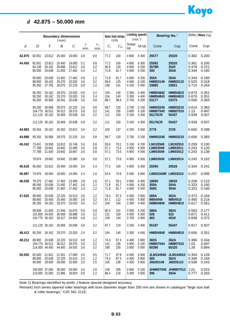
B 63
d 42.875 – 50.000 mm
25577 25520
25582 255203578R 3520355 354A
355A 354AHM803149 HM80311033885 33821
HM804842 HM804810HM804843 HM80481053177 53375
HM903249 HM903210HM807040 HM80701055175CR 55437
55176CR 55437
3776 3720
HM903248 HM903210
LM102949 LM102910LM603049 LM603011LM603049 LM603012
LM603049 LM603014
25590 25526
LM503349R LM503310
18690 18620359A 354A359S 354A
369A 362AM804049 M804010HM804846 HM804810
386A 382A528 522463 453X
55187 55437
HM804848 HM804810
365S 362AHM807044 HM80701065390 65320
JLM104948 JLM104910365 362AJM205149 JM205110
JHM807045 JHM807012396 394A
Bearing No. 1)
Cone Cup
Boundary dimensions(mm)
Basic load ratings(kN)
Limiting speeds(min–1)
d D T B Cr
min.r1
min.Cr C0r
Greaselub. Oil lub.
42.875
44.450
44.983
44.988
45.242
45.618
45.987
46.038
47.625
48.412
49.212
50.000
82.931 23.812 25.400 19.050 3.6 0.8 77.2 100 4 800 6 300
82.931 23.812 25.400 19.050 5.2 0.8 77.2 100 4 800 6 30084.138 30.162 30.886 23.812 3.6 3.2 95.8 120 4 600 6 20085.000 20.638 21.692 17.462 2.4 1.2 71.8 81.7 4 600 6 200
85.000 20.638 21.692 17.462 0.8 1.2 71.8 81.7 4 600 6 20088.900 30.162 29.370 23.020 3.6 3.2 99.6 125 4 600 6 10095.250 27.783 28.575 22.225 0.8 2.4 108 141 4 100 5 400
95.250 30.162 29.370 23.020 0.8 2.4 104 140 3 300 4 40095.250 30.162 29.370 23.020 3.6 2.4 104 140 3 300 4 40095.250 30.958 28.301 20.638 3.6 0.8 88.7 98.4 3 700 5 200
95.250 30.958 28.575 22.225 3.6 0.8 99.7 120 3 700 5 100104.775 36.512 36.512 28.575 3.6 3.2 141 195 3 800 5 100111.125 30.162 26.909 20.638 3.6 3.2 111 150 3 100 4 300
111.125 30.162 26.909 20.638 0.8 3.2 111 150 3 100 4 300
93.264 30.162 30.302 23.812 3.6 3.2 103 137 4 200 5 500
95.250 30.958 28.575 22.225 3.6 0.8 99.7 120 3 700 5 100
73.431 19.558 19.812 15.748 3.6 0.8 55.6 78.1 5 100 6 70077.788 19.842 19.842 15.080 3.6 0.8 57.1 73.5 4 900 6 50077.788 21.430 19.842 16.667 3.6 0.8 57.1 73.5 4 900 6 500
79.974 19.842 19.842 15.080 3.6 0.8 57.1 73.5 4 900 6 500
85.000 23.812 25.400 19.050 3.6 2.4 77.2 100 4 800 6 300
74.976 18.000 18.000 14.000 2.4 1.6 52.6 74.6 5 000 6 600
79.375 17.462 17.462 13.495 2.8 1.6 47.1 59.1 4 800 6 40085.000 20.638 21.692 17.462 3.6 1.2 71.8 81.7 4 600 6 20085.000 20.638 21.692 17.462 2.4 1.2 71.8 81.7 4 600 6 200
88.900 20.638 22.225 16.513 3.6 1.2 74.3 87.3 4 400 5 80088.900 25.400 25.400 19.050 3.6 3.2 87.1 112 4 400 5 90095.250 30.162 29.370 23.020 3.6 3.2 104 140 3 300 4 400
96.838 21.000 21.946 15.875 0.8 0.8 80.4 101 3 900 5 200101.600 34.925 36.068 26.988 3.6 3.2 131 159 4 000 5 300104.775 30.162 29.317 24.605 4.8 3.2 109 144 3 700 4 900
111.125 30.162 26.909 20.638 3.6 3.2 97.7 119 3 200 4 400
95.250 30.162 29.370 23.020 2.4 3.2 104 140 3 300 4 400
88.900 20.638 22.225 16.513 0.8 1.2 74.3 87.3 4 400 5 800104.775 36.512 36.512 28.575 3.6 3.2 141 195 3 800 5 100114.300 44.450 44.450 34.925 3.6 3.2 189 230 3 800 5 000
82.000 21.501 21.501 17.000 3.0 0.5 71.7 97.9 4 500 6 00088.900 20.638 22.225 16.513 2.0 1.2 74.3 87.3 4 400 5 80090.000 28.000 28.000 23.000 3.0 2.5 105 138 4 300 5 800
105.000 37.000 36.000 29.000 3.0 2.8 149 205 3 800 5 100110.000 22.000 21.996 18.824 0.8 1.2 86.4 116 3 400 4 500
0.382 0.200
0.361 0.2000.479 0.2210.344 0.160
0.344 0.1600.525 0.3180.714 0.264
0.673 0.3510.670 0.3510.558 0.363
0.614 0.3831.13 0.4970.939 0.507
0.939 0.507
0.650 0.288
0.606 0.383
0.209 0.1000.243 0.1200.243 0.138
0.243 0.152
0.344 0.241
0.207 0.095
0.208 0.1230.323 0.1600.323 0.160
0.373 0.1640.450 0.2160.617 0.351
0.563 0.1770.871 0.4110.838 0.372
0.817 0.507
0.606 0.351
0.366 0.1641.03 0.4971.28 0.894
0.304 0.1280.346 0.1640.508 0.243
1.01 0.5230.777 0.263
(Refer.) Mass (kg)
Cone Cup
Note 1) Bearings identified by prefix J feature special designed accuracy.Remark) Inch series tapered roller bearings with bore diameter larger than 200 mm are shown in catalogue "large size ball
& roller bearings," CAT. NO. 211E.
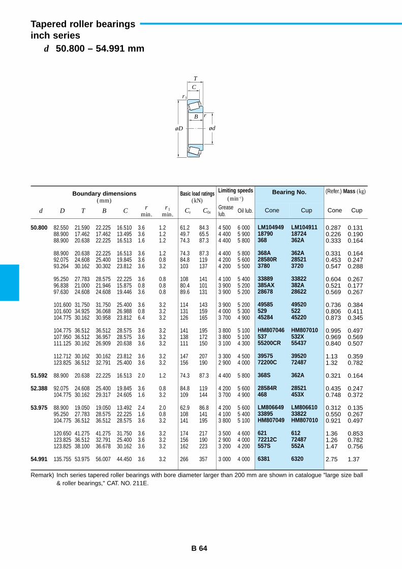
B 64
d 50.800 – 54.991 mm
Tapered roller bearingsinch series
LM104949 LM10491118790 18724368 362A
368A 362A28580R 285213780 3720
33889 33822385AX 382A28678 28622
49585 49520529 52245284 45220
HM807046 HM807010537 532X55200CR 55437
39575 3952072200C 72487
368S 362A
28584R 28521468 453X
LM806649 LM80661033895 33822HM807049 HM807010
621 61272212C 72487557S 552A
6381 6320
Bearing No.
Cone Cup
Boundary dimensions(mm)
Basic load ratings(kN)
Limiting speeds(min–1)
d D T B Cr
min.r1
min.Cr C0r
Greaselub. Oil lub.
50.800
51.592
52.388
53.975
54.991
82.550 21.590 22.225 16.510 3.6 1.2 61.2 84.3 4 500 6 00088.900 17.462 17.462 13.495 3.6 1.2 49.7 65.5 4 400 5 90088.900 20.638 22.225 16.513 1.6 1.2 74.3 87.3 4 400 5 800
88.900 20.638 22.225 16.513 3.6 1.2 74.3 87.3 4 400 5 80092.075 24.608 25.400 19.845 3.6 0.8 84.8 119 4 200 5 60093.264 30.162 30.302 23.812 3.6 3.2 103 137 4 200 5 500
95.250 27.783 28.575 22.225 3.6 0.8 108 141 4 100 5 40096.838 21.000 21.946 15.875 0.8 0.8 80.4 101 3 900 5 20097.630 24.608 24.608 19.446 3.6 0.8 89.6 131 3 900 5 200
101.600 31.750 31.750 25.400 3.6 3.2 114 143 3 900 5 200101.600 34.925 36.068 26.988 0.8 3.2 131 159 4 000 5 300104.775 30.162 30.958 23.812 6.4 3.2 126 165 3 700 4 900
104.775 36.512 36.512 28.575 3.6 3.2 141 195 3 800 5 100107.950 36.512 36.957 28.575 3.6 3.2 138 172 3 800 5 100111.125 30.162 26.909 20.638 3.6 3.2 111 150 3 100 4 300
112.712 30.162 30.162 23.812 3.6 3.2 147 207 3 300 4 500123.825 36.512 32.791 25.400 3.6 3.2 156 190 2 900 4 000
88.900 20.638 22.225 16.513 2.0 1.2 74.3 87.3 4 400 5 800
92.075 24.608 25.400 19.845 3.6 0.8 84.8 119 4 200 5 600104.775 30.162 29.317 24.605 1.6 3.2 109 144 3 700 4 900
88.900 19.050 19.050 13.492 2.4 2.0 62.9 86.8 4 200 5 60095.250 27.783 28.575 22.225 1.6 0.8 108 141 4 100 5 400104.775 36.512 36.512 28.575 3.6 3.2 141 195 3 800 5 100
120.650 41.275 41.275 31.750 3.6 3.2 174 217 3 500 4 600123.825 36.512 32.791 25.400 3.6 3.2 156 190 2 900 4 000123.825 38.100 36.678 30.162 3.6 3.2 162 223 3 200 4 200
135.755 53.975 56.007 44.450 3.6 3.2 266 357 3 000 4 000
0.287 0.1310.226 0.1900.333 0.164
0.331 0.1640.453 0.2470.547 0.288
0.604 0.2670.521 0.1770.569 0.267
0.736 0.3840.806 0.4110.873 0.345
0.995 0.4970.969 0.5690.840 0.507
1.13 0.3591.32 0.782
0.321 0.164
0.435 0.2470.748 0.372
0.312 0.1350.550 0.2670.921 0.497
1.36 0.8531.26 0.7821.47 0.756
2.75 1.37
(Refer.) Mass (kg)
Cone Cup
Remark) Inch series tapered roller bearings with bore diameter larger than 200 mm are shown in catalogue "large size ball& roller bearings," CAT. NO. 211E.
r
r1
ød
C
B
T
øD
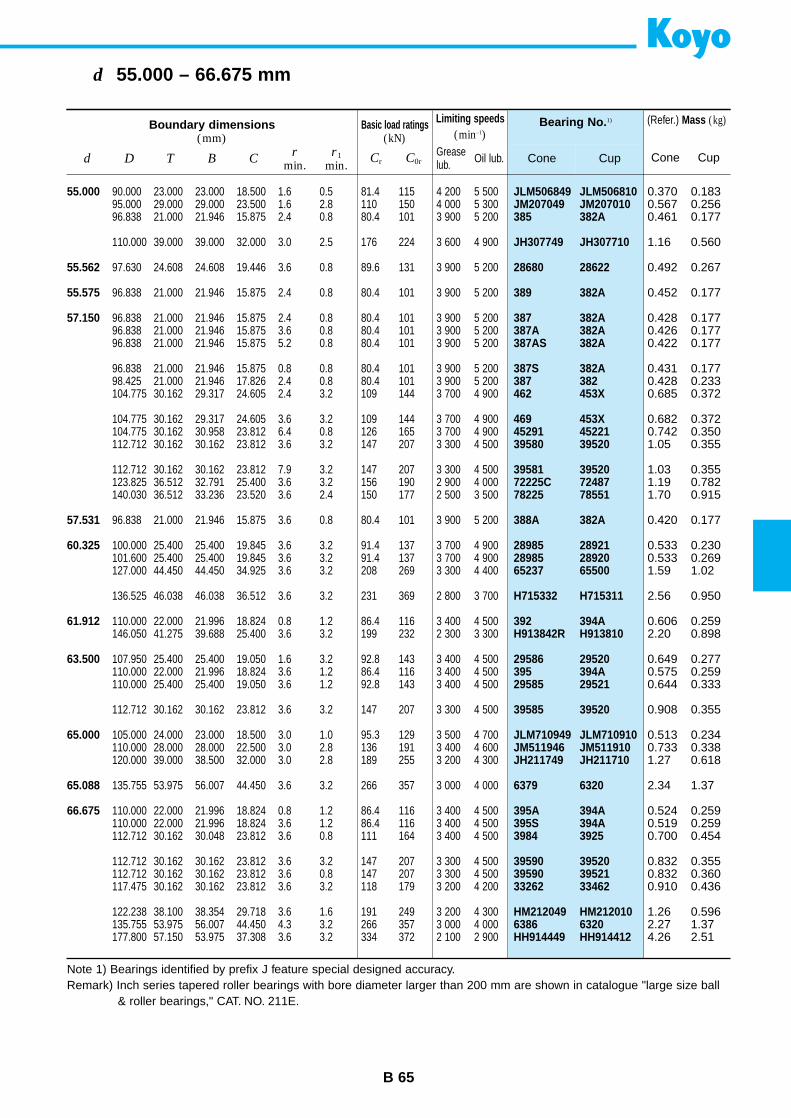
B 65
d 55.000 – 66.675 mm
JLM506849 JLM506810JM207049 JM207010385 382A
JH307749 JH307710
28680 28622
389 382A
387 382A387A 382A387AS 382A
387S 382A387 382462 453X
469 453X45291 4522139580 39520
39581 3952072225C 7248778225 78551
388A 382A
28985 2892128985 2892065237 65500
H715332 H715311
392 394AH913842R H913810
29586 29520395 394A29585 29521
39585 39520
JLM710949 JLM710910JM511946 JM511910JH211749 JH211710
6379 6320
395A 394A395S 394A3984 3925
39590 3952039590 3952133262 33462
HM212049 HM2120106386 6320HH914449 HH914412
Bearing No. 1)
Cone Cup
Boundary dimensions(mm)
Basic load ratings(kN)
Limiting speeds(min–1)
d D T B Cr
min.r1
min.Cr C0r
Greaselub. Oil lub.
55.000
55.562
55.575
57.150
57.531
60.325
61.912
63.500
65.000
65.088
66.675
90.000 23.000 23.000 18.500 1.6 0.5 81.4 115 4 200 5 50095.000 29.000 29.000 23.500 1.6 2.8 110 150 4 000 5 30096.838 21.000 21.946 15.875 2.4 0.8 80.4 101 3 900 5 200
110.000 39.000 39.000 32.000 3.0 2.5 176 224 3 600 4 900
97.630 24.608 24.608 19.446 3.6 0.8 89.6 131 3 900 5 200
96.838 21.000 21.946 15.875 2.4 0.8 80.4 101 3 900 5 200
96.838 21.000 21.946 15.875 2.4 0.8 80.4 101 3 900 5 20096.838 21.000 21.946 15.875 3.6 0.8 80.4 101 3 900 5 20096.838 21.000 21.946 15.875 5.2 0.8 80.4 101 3 900 5 200
96.838 21.000 21.946 15.875 0.8 0.8 80.4 101 3 900 5 20098.425 21.000 21.946 17.826 2.4 0.8 80.4 101 3 900 5 200104.775 30.162 29.317 24.605 2.4 3.2 109 144 3 700 4 900
104.775 30.162 29.317 24.605 3.6 3.2 109 144 3 700 4 900104.775 30.162 30.958 23.812 6.4 0.8 126 165 3 700 4 900112.712 30.162 30.162 23.812 3.6 3.2 147 207 3 300 4 500
112.712 30.162 30.162 23.812 7.9 3.2 147 207 3 300 4 500123.825 36.512 32.791 25.400 3.6 3.2 156 190 2 900 4 000140.030 36.512 33.236 23.520 3.6 2.4 150 177 2 500 3 500
96.838 21.000 21.946 15.875 3.6 0.8 80.4 101 3 900 5 200
100.000 25.400 25.400 19.845 3.6 3.2 91.4 137 3 700 4 900101.600 25.400 25.400 19.845 3.6 3.2 91.4 137 3 700 4 900127.000 44.450 44.450 34.925 3.6 3.2 208 269 3 300 4 400
136.525 46.038 46.038 36.512 3.6 3.2 231 369 2 800 3 700
110.000 22.000 21.996 18.824 0.8 1.2 86.4 116 3 400 4 500146.050 41.275 39.688 25.400 3.6 3.2 199 232 2 300 3 300
107.950 25.400 25.400 19.050 1.6 3.2 92.8 143 3 400 4 500110.000 22.000 21.996 18.824 3.6 1.2 86.4 116 3 400 4 500110.000 25.400 25.400 19.050 3.6 1.2 92.8 143 3 400 4 500
112.712 30.162 30.162 23.812 3.6 3.2 147 207 3 300 4 500
105.000 24.000 23.000 18.500 3.0 1.0 95.3 129 3 500 4 700110.000 28.000 28.000 22.500 3.0 2.8 136 191 3 400 4 600120.000 39.000 38.500 32.000 3.0 2.8 189 255 3 200 4 300
135.755 53.975 56.007 44.450 3.6 3.2 266 357 3 000 4 000
110.000 22.000 21.996 18.824 0.8 1.2 86.4 116 3 400 4 500110.000 22.000 21.996 18.824 3.6 1.2 86.4 116 3 400 4 500112.712 30.162 30.048 23.812 3.6 0.8 111 164 3 400 4 500
112.712 30.162 30.162 23.812 3.6 3.2 147 207 3 300 4 500112.712 30.162 30.162 23.812 3.6 0.8 147 207 3 300 4 500117.475 30.162 30.162 23.812 3.6 3.2 118 179 3 200 4 200
122.238 38.100 38.354 29.718 3.6 1.6 191 249 3 200 4 300135.755 53.975 56.007 44.450 4.3 3.2 266 357 3 000 4 000177.800 57.150 53.975 37.308 3.6 3.2 334 372 2 100 2 900
0.370 0.1830.567 0.2560.461 0.177
1.16 0.560
0.492 0.267
0.452 0.177
0.428 0.1770.426 0.1770.422 0.177
0.431 0.1770.428 0.2330.685 0.372
0.682 0.3720.742 0.3501.05 0.355
1.03 0.3551.19 0.7821.70 0.915
0.420 0.177
0.533 0.2300.533 0.2691.59 1.02
2.56 0.950
0.606 0.2592.20 0.898
0.649 0.2770.575 0.2590.644 0.333
0.908 0.355
0.513 0.2340.733 0.3381.27 0.618
2.34 1.37
0.524 0.2590.519 0.2590.700 0.454
0.832 0.3550.832 0.3600.910 0.436
1.26 0.5962.27 1.374.26 2.51
(Refer.) Mass (kg)
Cone Cup
Note 1) Bearings identified by prefix J feature special designed accuracy.Remark) Inch series tapered roller bearings with bore diameter larger than 200 mm are shown in catalogue "large size ball
& roller bearings," CAT. NO. 211E.
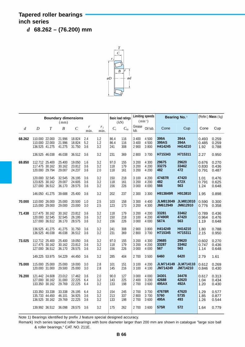
B 66
d 68.262 – (76.200) mm
Tapered roller bearingsinch series
399A 394A399AS 394AH414245 H414210
H715343 H715311
29675 2962033275 33462482 472
47487R 47420482 472X566 563
H913849R H913810
JLM813049 JLM813010JM612949 JM612910
33281 3346247490R 47420567A 563
H414249 H414210H715345 H715311
29685 2962033287 33462567 563
6460 6420
JLM714149 JLM714110JM714249 JM714210
34301 3447842688 42620495AX 492A
47678R 476205760 5735495A 493
575R 572
Bearing No. 1)
Cone Cup
Boundary dimensions(mm)
Basic load ratings(kN)
Limiting speeds(min–1)
d D T B Cr
min.r1
min.Cr C0r
Greaselub. Oil lub.
68.262
69.850
70.000
71.438
73.025
75.000
76.200
110.000 22.000 21.996 18.824 2.4 1.2 86.4 116 3 400 4 500110.000 22.000 21.996 18.824 5.2 1.2 86.4 116 3 400 4 500136.525 41.275 41.275 31.750 3.6 3.2 241 308 2 900 3 800
136.525 46.038 46.038 36.512 3.6 3.2 231 369 2 800 3 700
112.712 25.400 25.400 19.050 1.6 3.2 97.0 155 3 200 4 300117.475 30.162 30.162 23.812 3.6 3.2 118 179 3 200 4 200120.000 29.794 29.007 24.237 3.6 2.0 118 161 3 200 4 200
120.000 32.545 32.545 26.195 3.6 3.2 150 218 3 100 4 200123.825 30.162 29.007 24.605 3.6 3.2 118 161 3 200 4 200127.000 36.512 36.170 28.575 3.6 3.2 156 226 3 000 4 000
146.050 41.275 39.688 25.400 3.6 3.2 202 237 2 300 3 300
110.000 26.000 25.000 20.500 1.0 2.5 103 158 3 300 4 400115.000 29.000 29.000 23.000 3.0 2.5 123 173 3 200 4 300
117.475 30.162 30.162 23.812 3.6 3.2 118 179 3 200 4 200120.000 32.545 32.545 26.195 3.6 3.2 150 218 3 100 4 200127.000 36.512 36.170 28.575 3.6 3.2 156 226 3 000 4 000
136.525 41.275 41.275 31.750 3.6 3.2 241 308 2 900 3 800136.525 46.038 46.038 36.512 3.6 3.2 231 369 2 800 3 700
112.712 25.400 25.400 19.050 3.6 3.2 97.0 155 3 200 4 300117.475 30.162 30.162 23.812 3.6 3.2 118 179 3 200 4 200127.000 36.512 36.170 28.575 3.6 3.2 156 226 3 000 4 000
149.225 53.975 54.229 44.450 3.6 3.2 285 404 2 700 3 500
115.000 25.000 25.000 19.000 3.0 2.8 101 151 3 100 4 200120.000 31.000 29.500 25.000 3.0 2.8 145 216 3 100 4 100
121.442 24.608 23.012 17.462 3.6 2.0 90.0 127 3 000 4 000127.000 30.162 31.000 22.225 6.4 3.2 143 225 2 400 3 200133.350 30.162 29.769 22.225 6.4 3.2 133 198 2 700 3 600
133.350 33.338 33.338 26.195 6.4 3.2 154 245 2 700 3 700135.733 44.450 46.101 34.925 3.6 3.2 213 337 2 800 3 700136.525 30.162 29.769 22.225 3.6 3.2 133 198 2 700 3 600
139.992 36.512 36.098 28.575 3.6 3.2 175 262 2 700 3 600
0.493 0.2590.485 0.2591.92 0.788
2.27 0.950
0.676 0.2700.830 0.4360.791 0.487
1.01 0.4760.791 0.6251.24 0.648
1.95 0.898
0.590 0.3000.776 0.358
0.789 0.4360.964 0.4761.19 0.648
1.80 0.7882.15 0.950
0.602 0.2700.747 0.4361.14 0.648
2.79 1.61
0.612 0.2690.846 0.430
0.617 0.3131.04 0.4341.20 0.430
1.29 0.5771.85 0.8771.26 0.544
1.64 0.779
(Refer.) Mass (kg)
Cone Cup
Note 1) Bearings identified by prefix J feature special designed accuracy.Remark) Inch series tapered roller bearings with bore diameter larger than 200 mm are shown in catalogue "large size ball
& roller bearings," CAT. NO. 211E.
r
r1
ød
C
B
T
øD
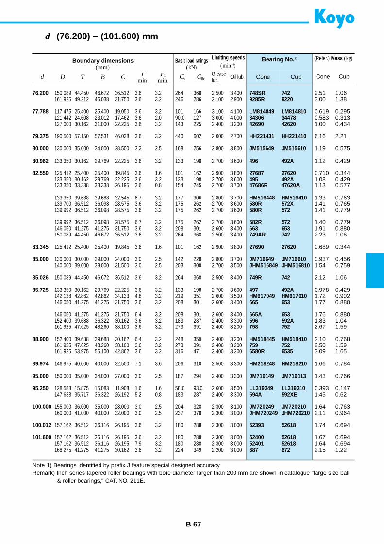
B 67
d (76.200) – (101.600) mm
748SR 7429285R 9220
LM814849 LM81481034306 3447842690 42620
HH221431 HH221410
JM515649 JM515610
496 492A
27687 27620495 492A47686R 47620A
HM516448 HM516410580R 572X580R 572
582R 572663 653749AR 742
27690 27620
JM716649 JM716610JHM516849 JHM516810
749R 742
497 492AHM617049 HM617010665 653
665A 653596 592A758 752
HM518445 HM518410759 7526580R 6535
HM218248 HM218210
JM719149 JM719113
LL319349 LL319310594A 592XE
JM720249 JM720210JHM720249 JHM720210
52393 52618
52400 5261852401 52618687 672
Bearing No. 1)
Cone Cup
Boundary dimensions(mm)
Basic load ratings(kN)
Limiting speeds(min–1)
d D T B Cr
min.r1
min.Cr C0r
Greaselub. Oil lub.
76.200
77.788
79.375
80.000
80.962
82.550
83.345
85.000
85.026
85.725
88.900
89.974
95.000
95.250
100.000
100.012
101.600
150.089 44.450 46.672 36.512 3.6 3.2 264 368 2 500 3 400161.925 49.212 46.038 31.750 3.6 3.2 246 286 2 100 2 900
117.475 25.400 25.400 19.050 3.6 3.2 101 166 3 100 4 100121.442 24.608 23.012 17.462 3.6 2.0 90.0 127 3 000 4 000127.000 30.162 31.000 22.225 3.6 3.2 143 225 2 400 3 200
190.500 57.150 57.531 46.038 3.6 3.2 440 602 2 000 2 700
130.000 35.000 34.000 28.500 3.2 2.5 168 256 2 800 3 800
133.350 30.162 29.769 22.225 3.6 3.2 133 198 2 700 3 600
125.412 25.400 25.400 19.845 3.6 1.6 101 162 2 900 3 800133.350 30.162 29.769 22.225 3.6 3.2 133 198 2 700 3 600133.350 33.338 33.338 26.195 3.6 0.8 154 245 2 700 3 700
133.350 39.688 39.688 32.545 6.7 3.2 177 306 2 800 3 700139.700 36.512 36.098 28.575 3.6 3.2 175 262 2 700 3 600139.992 36.512 36.098 28.575 3.6 3.2 175 262 2 700 3 600
139.992 36.512 36.098 28.575 6.7 3.2 175 262 2 700 3 600146.050 41.275 41.275 31.750 3.6 3.2 208 301 2 600 3 400150.089 44.450 46.672 36.512 3.6 3.2 264 368 2 500 3 400
125.412 25.400 25.400 19.845 3.6 1.6 101 162 2 900 3 800
130.000 30.000 29.000 24.000 3.0 2.5 142 228 2 800 3 700140.000 39.000 38.000 31.500 3.0 2.5 203 308 2 700 3 500
150.089 44.450 46.672 36.512 3.6 3.2 264 368 2 500 3 400
133.350 30.162 29.769 22.225 3.6 3.2 133 198 2 700 3 600142.138 42.862 42.862 34.133 4.8 3.2 219 351 2 600 3 500146.050 41.275 41.275 31.750 3.6 3.2 208 301 2 600 3 400
146.050 41.275 41.275 31.750 6.4 3.2 208 301 2 600 3 400152.400 39.688 36.322 30.162 3.6 3.2 183 287 2 400 3 300161.925 47.625 48.260 38.100 3.6 3.2 273 391 2 400 3 200
152.400 39.688 39.688 30.162 6.4 3.2 248 359 2 400 3 200161.925 47.625 48.260 38.100 3.6 3.2 273 391 2 400 3 200161.925 53.975 55.100 42.862 3.6 3.2 316 471 2 400 3 200
146.975 40.000 40.000 32.500 7.1 3.6 206 310 2 500 3 300
150.000 35.000 34.000 27.000 3.0 2.5 187 294 2 400 3 300
128.588 15.875 15.083 11.908 1.6 1.6 58.0 93.0 2 600 3 500147.638 35.717 36.322 26.192 5.2 0.8 183 287 2 400 3 300
155.000 36.000 35.000 28.000 3.0 2.5 204 328 2 300 3 100160.000 41.000 40.000 32.000 3.0 2.5 237 378 2 300 3 000
157.162 36.512 36.116 26.195 3.6 3.2 180 288 2 300 3 000
157.162 36.512 36.116 26.195 3.6 3.2 180 288 2 300 3 000157.162 36.512 36.116 26.195 7.9 3.2 180 288 2 300 3 000168.275 41.275 41.275 30.162 3.6 3.2 224 349 2 200 3 000
2.51 1.063.00 1.38
0.619 0.2950.583 0.3131.00 0.434
6.16 2.21
1.19 0.575
1.12 0.429
0.710 0.3441.08 0.4291.13 0.577
1.33 0.7631.41 0.7651.41 0.779
1.40 0.7791.91 0.8802.23 1.06
0.689 0.344
0.937 0.4561.54 0.759
2.12 1.06
0.978 0.4291.72 0.9021.77 0.880
1.76 0.8801.83 1.042.67 1.59
2.10 0.7682.50 1.593.09 1.65
1.66 0.784
1.43 0.766
0.393 0.1471.45 0.62
1.64 0.7632.11 0.964
1.74 0.694
1.67 0.6941.64 0.6942.15 1.22
(Refer.) Mass (kg)
Cone Cup
Note 1) Bearings identified by prefix J feature special designed accuracy.Remark) Inch series tapered roller bearings with bore diameter larger than 200 mm are shown in catalogue "large size ball
& roller bearings," CAT. NO. 211E.
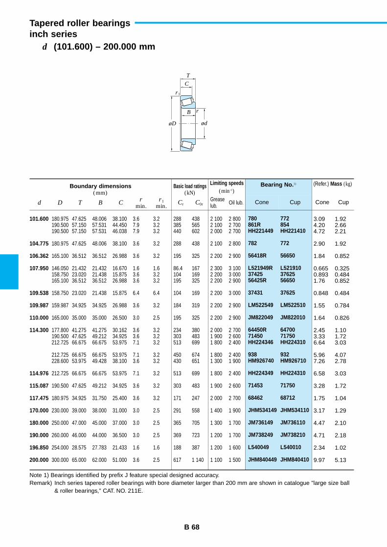
B 68
d (101.600) – 200.000 mm
Tapered roller bearingsinch series
780 772861R 854HH221449 HH221410
782 772
56418R 56650
L521949R L52191037425 3762556425R 56650
37431 37625
LM522549 LM522510
JM822049 JM822010
64450R 6470071450 71750HH224346 HH224310
938 932HM926740 HM926710
HH224349 HH224310
71453 71750
68462 68712
JHM534149 JHM534110
JM736149 JM736110
JM738249 JM738210
L540049 L540010
JHM840449 JHM840410
Bearing No. 1)
Cone Cup
Boundary dimensions(mm)
Basic load ratings(kN)
Limiting speeds(min–1)
d D T B Cr
min.r1
min.Cr C0r
Greaselub. Oil lub.
101.600
104.775
106.362
107.950
109.538
109.987
110.000
114.300
114.976
115.087
117.475
170.000
180.000
190.000
196.850
200.000
180.975 47.625 48.006 38.100 3.6 3.2 288 438 2 100 2 800190.500 57.150 57.531 44.450 7.9 3.2 385 565 2 100 2 700190.500 57.150 57.531 46.038 7.9 3.2 440 602 2 000 2 700
180.975 47.625 48.006 38.100 3.6 3.2 288 438 2 100 2 800
165.100 36.512 36.512 26.988 3.6 3.2 195 325 2 200 2 900
146.050 21.432 21.432 16.670 1.6 1.6 86.4 167 2 300 3 100158.750 23.020 21.438 15.875 3.6 3.2 104 169 2 200 3 000165.100 36.512 36.512 26.988 3.6 3.2 195 325 2 200 2 900
158.750 23.020 21.438 15.875 6.4 6.4 104 169 2 200 3 000
159.987 34.925 34.925 26.988 3.6 3.2 184 319 2 200 2 900
165.000 35.000 35.000 26.500 3.0 2.5 195 325 2 200 2 900
177.800 41.275 41.275 30.162 3.6 3.2 234 380 2 000 2 700190.500 47.625 49.212 34.925 3.6 3.2 303 483 1 900 2 600212.725 66.675 66.675 53.975 7.1 3.2 513 699 1 800 2 400
212.725 66.675 66.675 53.975 7.1 3.2 450 674 1 800 2 400228.600 53.975 49.428 38.100 3.6 3.2 430 651 1 300 1 900
212.725 66.675 66.675 53.975 7.1 3.2 513 699 1 800 2 400
190.500 47.625 49.212 34.925 3.6 3.2 303 483 1 900 2 600
180.975 34.925 31.750 25.400 3.6 3.2 171 247 2 000 2 700
230.000 39.000 38.000 31.000 3.0 2.5 291 558 1 400 1 900
250.000 47.000 45.000 37.000 3.0 2.5 365 705 1 300 1 700
260.000 46.000 44.000 36.500 3.0 2.5 369 723 1 200 1 700
254.000 28.575 27.783 21.433 1.6 1.6 188 387 1 200 1 600
300.000 65.000 62.000 51.000 3.6 2.5 617 1 140 1 100 1 500
3.09 1.924.20 2.664.72 2.21
2.90 1.92
1.84 0.852
0.665 0.3250.893 0.4841.76 0.852
0.848 0.484
1.55 0.784
1.64 0.826
2.45 1.103.33 1.726.64 3.03
5.96 4.077.26 2.78
6.58 3.03
3.28 1.72
1.75 1.04
3.17 1.29
4.47 2.10
4.71 2.18
2.34 1.02
9.97 5.13
(Refer.) Mass (kg)
Cone Cup
Note 1) Bearings identified by prefix J feature special designed accuracy.Remark) Inch series tapered roller bearings with bore diameter larger than 200 mm are shown in catalogue "large size ball
& roller bearings," CAT. NO. 211E.
r
r1
ød
C
B
T
øD

B 69
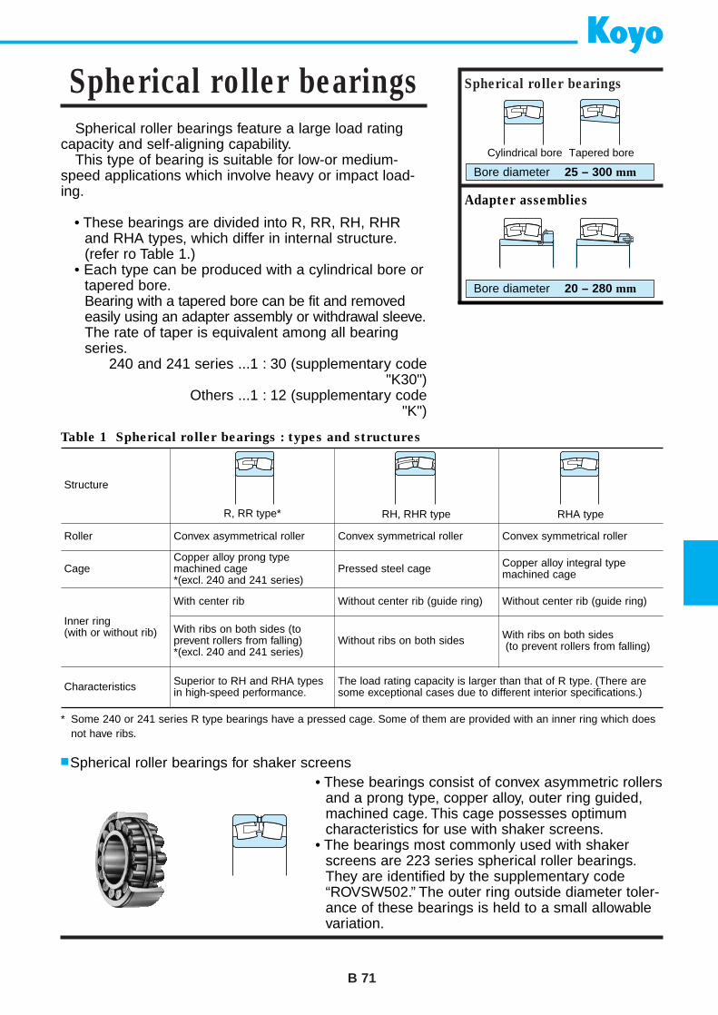
Cylindrical bore Tapered bore
Spherical roller bearings feature a large load ratingcapacity and self-aligning capability.
This type of bearing is suitable for low-or medium-speed applications which involve heavy or impact load-ing.
• These bearings are divided into R, RR, RH, RHRand RHA types, which differ in internal structure.(refer ro Table 1.)
• Each type can be produced with a cylindrical bore ortapered bore.Bearing with a tapered bore can be fit and removedeasily using an adapter assembly or withdrawal sleeve.The rate of taper is equivalent among all bearingseries.
240 and 241 series ...1 : 30 (supplementary code"K30")
Others ...1 : 12 (supplementary code"K")
B 71
Spherical roller bearings Spherical roller bearings
Bore diameter 25 – 300 mm
* Some 240 or 241 series R type bearings have a pressed cage. Some of them are provided with an inner ring which doesnot have ribs.
Adapter assemblies
Bore diameter 20 – 280 mm
Table 1 Spherical roller bearings : types and structures
Structure
Roller Convex asymmetrical roller
CageCopper alloy prong typemachined cage *(excl. 240 and 241 series)
Inner ring (with or without rib)
With center rib
Characteristics Superior to RH and RHA typesin high-speed performance.
With ribs on both sides (to prevent rollers from falling) *(excl. 240 and 241 series)
Convex symmetrical roller
Pressed steel cage
Without center rib (guide ring)
The load rating capacity is larger than that of R type. (There aresome exceptional cases due to different interior specifications.)
Without ribs on both sides
Convex symmetrical roller
Copper alloy integral typemachined cage
Without center rib (guide ring)
With ribs on both sides(to prevent rollers from falling)
Spherical roller bearings for shaker screens• These bearings consist of convex asymmetric rollers
and a prong type, copper alloy, outer ring guided,machined cage. This cage possesses optimumcharacteristics for use with shaker screens.
• The bearings most commonly used with shakerscreens are 223 series spherical roller bearings.They are identified by the supplementary code“ROVSW502.” The outer ring outside diameter toler-ance of these bearings is held to a small allowablevariation.
R, RR type* RH, RHR type RHA type
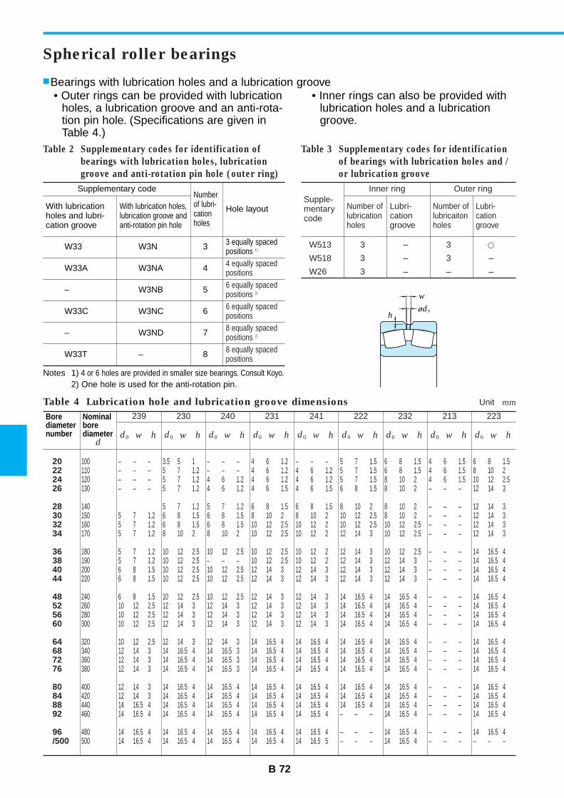
B 72
Supplementary codeNumberof lubri-cationholes
Hole layoutWith lubricationholes and lubri-cation groove
With lubrication holes,lubrication groove andanti-rotation pin hole
W33 W3N 3
W33A W3NA 4
– W3NB 5
W33C W3NC 6
– W3ND 7
W33T – 8
3 equally spacedpositions 1)
4 equally spacedpositions6 equally spacedpositions 2)
6 equally spacedpositions8 equally spacedpositions 2)
8 equally spacedpositions
Table 2 Supplementary codes for identification of
bearings with lubrication holes, lubrication
groove and anti-rotation pin hole (outer ring)
Table 4 Lubrication hole and lubrication groove dimensions Unit mm
Inner ringSupple-mentarycode
Number oflubricationholes
Lubri-cationgroove
Outer ring
Number oflubricaitonholes
Lubri-cationgroove
W513 3 – 3 ™W518 3 – 3 –
W26 3 – – –
Table 3 Supplementary codes for identification
of bearings with lubrication holes and /
or lubrication groove
Spherical roller bearings
Bearings with lubrication holes and a lubrication groove• Outer rings can be provided with lubrication
holes, a lubrication groove and an anti-rota-tion pin hole. (Specifications are given inTable 4.)
• Inner rings can also be provided withlubrication holes and a lubricationgroove.
Notes 1) 4 or 6 holes are provided in smaller size bearings. Consult Koyo.2) One hole is used for the anti-rotation pin.
Borediameternumber
Nominalborediameter
d
239
d0 w h
230
d0 w h
240
d0 w h
231
d0 w h
241
d0 w h
222
d0 w h
232
d0 w h
213
d0 w h
223
d0 w h
20222426
28303234
36384044
48525660
64687276
80848892
96/500
100 – – – 3.5 5 1 – – – 4 6 1.2110 – – – 5 7 1.2 – – – 4 6 1.2120 – – – 5 7 1.2 4 6 1.2 4 6 1.2130 – – – 5 7 1.2 4 6 1.2 4 6 1.5
140 5 7 1.2 5 7 1.2 6 8 1.5150 5 7 1.2 6 8 1.5 6 8 1.5 8 10 2160 5 7 1.2 6 8 1.5 6 8 1.5 10 12 2.5170 5 7 1.2 8 10 2 8 10 2 10 12 2.5
180 5 7 1.2 10 12 2.5 10 12 2.5 10 12 2.5190 5 7 1.2 10 12 2.5 – – – 10 12 2.5200 6 8 1.5 10 12 2.5 10 12 2.5 12 14 3220 6 8 1.5 10 12 2.5 10 12 2.5 12 14 3
240 6 8 1.5 10 12 2.5 10 12 2.5 12 14 3260 10 12 2.5 12 14 3 12 14 3 12 14 3280 10 12 2.5 12 14 3 12 14 3 12 14 3300 10 12 2.5 12 14 3 12 14 3 12 14 3
320 10 12 2.5 12 14 3 12 14 3 14 16.5 4340 12 14 3 14 16.5 4 14 16.5 3 14 16.5 4360 12 14 3 14 16.5 4 14 16.5 3 14 16.5 4380 12 14 3 14 16.5 4 14 16.5 3 14 16.5 4
400 12 14 3 14 16.5 4 14 16.5 4 14 16.5 4420 12 14 3 14 16.5 4 14 16.5 4 14 16.5 4440 14 16.5 4 14 16.5 4 14 16.5 4 14 16.5 4460 14 16.5 4 14 16.5 4 14 16.5 4 14 16.5 4
480 14 16.5 4 14 16.5 4 14 16.5 4 14 16.5 4500 14 16.5 4 14 16.5 4 14 16.5 4 14 16.5 4
– – – 5 7 1.5 6 8 1.5 4 6 1.5 6 8 1.54 6 1.2 5 7 1.5 6 8 1.5 4 6 1.5 8 10 24 6 1.2 5 7 1.5 8 10 2 4 6 1.5 10 12 2.54 6 1.5 6 8 1.5 8 10 2 – – – 12 14 3
6 8 1.5 8 10 2 8 10 2 – – – 12 14 38 10 2 10 12 2.5 8 10 2 – – – 12 14 310 12 2 10 12 2.5 10 12 2.5 – – – 12 14 310 12 2 12 14 3 10 12 2.5 – – – 12 14 3
10 12 2 12 14 3 10 12 2.5 – – – 14 16.5 410 12 2 12 14 3 12 14 3 – – – 14 16.5 412 14 3 12 14 3 12 14 3 – – – 14 16.5 412 14 3 12 14 3 12 14 3 – – – 14 16.5 4
12 14 3 14 16.5 4 14 16.5 4 – – – 14 16.5 412 14 3 14 16.5 4 14 16.5 4 – – – 14 16.5 412 14 3 14 16.5 4 14 16.5 4 – – – 14 16.5 412 14 3 14 16.5 4 14 16.5 4 – – – 14 16.5 4
14 16.5 4 14 16.5 4 14 16.5 4 – – – 14 16.5 414 16.5 4 14 16.5 4 14 16.5 4 – – – 14 16.5 414 16.5 4 14 16.5 4 14 16.5 4 – – – 14 16.5 414 16.5 4 14 16.5 4 14 16.5 4 – – – 14 16.5 4
14 16.5 4 14 16.5 4 14 16.5 4 – – – 14 16.5 414 16.5 4 14 16.5 4 14 16.5 4 – – – 14 16.5 414 16.5 4 14 16.5 4 14 16.5 4 – – – 14 16.5 414 16.5 4 – – – 14 16.5 4 – – – 14 16.5 4
14 16.5 4 – – – 14 16.5 4 – – – 14 16.5 414 16.5 5 – – – 14 16.5 4 – – – – – –
ød0
w
h
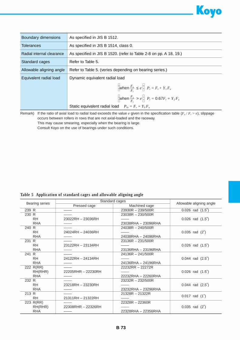
B 73
Boundary dimensions
Tolerances
Radial internal clearance
Standard cages
Allowable aligning angle
Equivalent radial load
As specified in JIS B 1512.
As specified in JIS B 1514, class 0.
As specified in JIS B 1520. (refer to Table 2-8 on pp. A 18, 19.)
Refer to Table 5.
Refer to Table 5. (veries depending on bearing series.)
Dynamic equivalent radial load
Static equivalent radial load P0r = Fr + Y0 Fa
when ≤ e Pr = Fr + Y1 Fa
when > e Pr = 0.67Fr + Y2 FaFa
Fr
Fa
Fr
Remark) If the ratio of axial load to radial load exceeds the value e given in the specification table (Fa / Fr > e), slippageoccurs between rollers in rows that are not axial-loaded and the raceway.This may cause smearing, especially when the bearing is large.Consult Koyo on the use of bearings under such conditions.
Bearing seriesStandard cages
Allowable aligning anglePressed cage Machined cage
239 R230 R
RHRHA
240 RRHRHA
231 RRHRHA
241 RRHRHA
222 R(RR)RH(RHR)RHA
232 RRHRHA
213 RRH
223 R(RR)RH(RHR)RHA
––––––––23022RH – 23036RH––––––––24024RH – 24036RH––––––––23122RH – 23134RH––––––––24122RH – 24134RH––––––––22205RHR – 22230RH––––––––23218RH – 23230RH––––––––21311RH – 21322RH––––22308RHR – 22326RH––––
23930R – 239/500R23038R – 230/500R––––23038RHA – 23096RHA24038R – 240/500R––––24038RHA – 24096RHA23136R – 231/500R––––23136RHA – 23196RHA24136R – 241/500R––––24136RHA – 24196RHA22232RR – 22272R––––22232RHA – 22260RHA23232R – 232/500R––––23232RHA – 23296RHA21328R – 21322R––––22328R – 22360R––––22328RHA – 22356RHA
0.026 rad (1.5˚)
0.026 rad (1.5˚)
0.035 rad (2˚)
0.026 rad (1.5˚)
0.044 rad (2.5˚)
0.026 rad (1.5˚)
0.044 rad (2.5˚)
0.017 rad (1˚)
0.035 rad (2˚)
Table 5 Application of standard cages and allowable aligning angle

B 74
d 25 – 80 mm
Spherical roller bearings
22205RHR 22205RHRK
22206RHR 22206RHRK21306RH 21306RHK
22207RHR 22207RHRK21307RH 21307RHK
22208RHR 22208RHRK21308RH 21308RHK22308RHR 22308RHRK
22209RHR 22209RHRK21309RH 21309RHK22309RHR 22309RHRK
22210RHR 22210RHRK21310RH 21310RHK22310RHR 22310RHRK
22211RHR 22211RHRK21311RH 21311RHK22311RHR 22311RHRK
22212RHR 22212RHRK21312RH 21312RHK22312RHR 22312RHRK
22213RHR 22213RHRK21313RH 21313RHK22313RHR 22313RHRK
22214RHR 22214RHRK21314RH 21314RHK22314RHR 22314RHRK
22215RHR 22215RHRK21315RH 21315RHK22315RHR 22315RHRK
22216RHR 22216RHRK21316RH 21316RHK22316RHR 22316RHRK
Bearing No.
Cylindricalbore
Taperedbore
Boundary dimensions(mm)
Basic load ratings(kN)
Limiting speeds(min–1)
d D Br
min.Cr C0r
Greaselub. Oil lub.
25
30
35
40
45
50
55
60
65
70
75
80
52 18 1 45.4 48.1 7 000 9 300
62 20 1 61.2 65.9 5 900 7 90072 19 1.1 59.3 62.7 5 200 7 000
72 23 1.1 80.3 88.7 5 000 6 70080 21 1.5 69.6 75.3 4 500 6 000
80 23 1.1 90.9 102 4 500 6 00090 23 1.5 85.7 95.5 4 100 5 50090 33 1.5 136 152 4 100 5 500
85 23 1.1 95.6 110 4 200 5 600100 25 1.5 108 124 3 600 4 900100 36 1.5 166 183 3 700 4 900
90 23 1.1 103 122 3 900 5 200110 27 2 128 151 3 300 4 400110 40 2 204 237 3 300 4 500
100 25 1.5 124 144 3 400 4 600120 29 2 144 165 3 000 4 100120 43 2 236 264 3 000 4 000
110 28 1.5 153 181 3 100 4 200130 31 2.1 168 193 2 800 3 700130 46 2.1 283 334 2 800 3 700
120 31 1.5 178 211 2 900 3 800140 33 2.1 194 232 2 600 3 400140 48 2.1 305 360 2 600 3 400
125 31 1.5 187 222 2 700 3 600150 35 2.1 215 260 2 400 3 200150 51 2.1 348 413 2 400 3 200
130 31 1.5 193 236 2 600 3 400160 37 2.1 246 298 2 200 3 000160 55 2.1 393 473 2 200 3 000
140 33 2 217 271 2 400 3 200170 39 2.1 275 339 2 100 2 800170 58 2.1 431 521 2 100 2 800
0.220 0.215
0.360 0.3500.380 0.370
0.550 0.5400.510 0.500
0.660 0.6500.710 0.7001.25 1.23
0.720 0.7100.950 0.9401.62 1.59
0.780 0.7701.20 1.182.21 2.18
1.05 1.041.60 1.582.72 2.67
1.45 1.431.95 1.923.43 3.37
1.84 1.812.45 2.414.15 4.07
1.94 1.913.00 2.955.01 4.92
2.05 2.013.55 3.506.13 6.02
2.61 2.574.20 4.147.18 7.04
(Refer.) Mass (kg)
Cylindricalbore
Taperedbore
Remark) Standard cage types used for the above bearings are shown in Table 5 earlier in this section.
r rr
r
r
r
B B
rr
r
B
ød ødøD ød ødøD ød ødøD
Cylindricalbore
Taperedbore
R, RR RH, RHR RHA
Cylindricalbore
Taperedbore
Cylindricalbore
Taperedbore
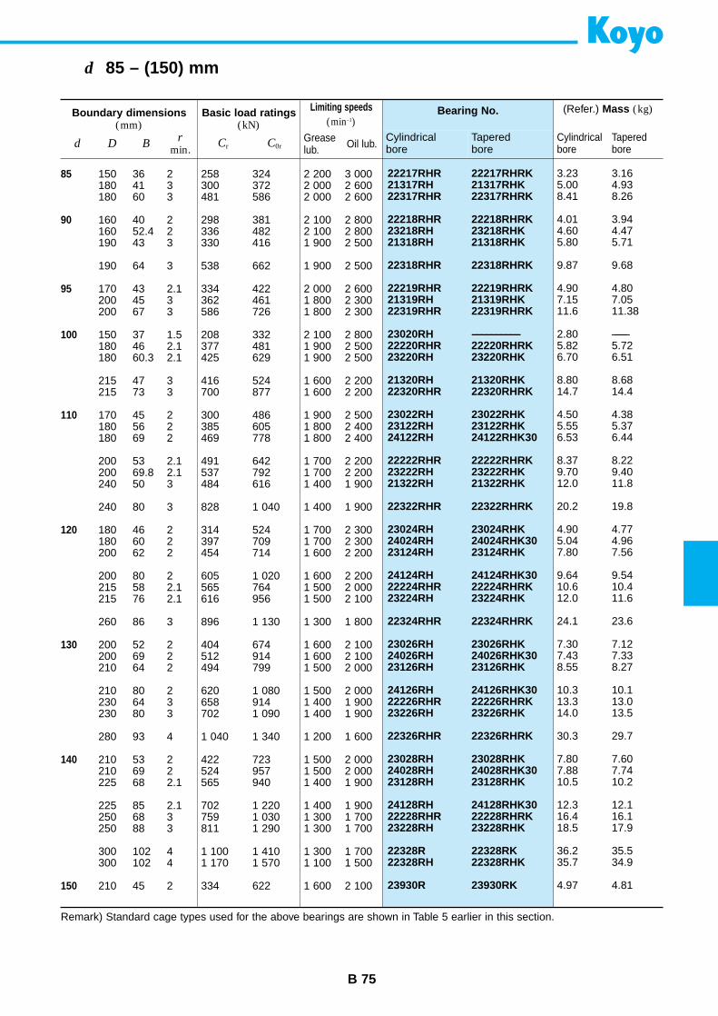
B 75
d 85 – (150) mm
22217RHR 22217RHRK21317RH 21317RHK22317RHR 22317RHRK
22218RHR 22218RHRK23218RH 23218RHK21318RH 21318RHK
22318RHR 22318RHRK
22219RHR 22219RHRK21319RH 21319RHK22319RHR 22319RHRK
23020RH ––––––––––22220RHR 22220RHRK23220RH 23220RHK
21320RH 21320RHK22320RHR 22320RHRK
23022RH 23022RHK23122RH 23122RHK24122RH 24122RHK30
22222RHR 22222RHRK23222RH 23222RHK21322RH 21322RHK
22322RHR 22322RHRK
23024RH 23024RHK24024RH 24024RHK3023124RH 23124RHK
24124RH 24124RHK3022224RHR 22224RHRK23224RH 23224RHK
22324RHR 22324RHRK
23026RH 23026RHK24026RH 24026RHK3023126RH 23126RHK
24126RH 24126RHK3022226RHR 22226RHRK23226RH 23226RHK
22326RHR 22326RHRK
23028RH 23028RHK24028RH 24028RHK3023128RH 23128RHK
24128RH 24128RHK3022228RHR 22228RHRK23228RH 23228RHK
22328R 22328RK22328RH 22328RHK
23930R 23930RK
Bearing No.
Cylindricalbore
Taperedbore
Boundary dimensions(mm)
Basic load ratings(kN)
Limiting speeds(min–1)
d D Br
min.Cr C0r
Greaselub. Oil lub.
85
90
95
100
110
120
130
140
150
150 36 2 258 324 2 200 3 000180 41 3 300 372 2 000 2 600180 60 3 481 586 2 000 2 600
160 40 2 298 381 2 100 2 800160 52.4 2 336 482 2 100 2 800190 43 3 330 416 1 900 2 500
190 64 3 538 662 1 900 2 500
170 43 2.1 334 422 2 000 2 600200 45 3 362 461 1 800 2 300200 67 3 586 726 1 800 2 300
150 37 1.5 208 332 2 100 2 800180 46 2.1 377 481 1 900 2 500180 60.3 2.1 425 629 1 900 2 500
215 47 3 416 524 1 600 2 200215 73 3 700 877 1 600 2 200
170 45 2 300 486 1 900 2 500180 56 2 385 605 1 800 2 400180 69 2 469 778 1 800 2 400
200 53 2.1 491 642 1 700 2 200200 69.8 2.1 537 792 1 700 2 200240 50 3 484 616 1 400 1 900
240 80 3 828 1 040 1 400 1 900
180 46 2 314 524 1 700 2 300180 60 2 397 709 1 700 2 300200 62 2 454 714 1 600 2 200
200 80 2 605 1 020 1 600 2 200215 58 2.1 565 764 1 500 2 000215 76 2.1 616 956 1 500 2 100
260 86 3 896 1 130 1 300 1 800
200 52 2 404 674 1 600 2 100200 69 2 512 914 1 600 2 100210 64 2 494 799 1 500 2 000
210 80 2 620 1 080 1 500 2 000230 64 3 658 914 1 400 1 900230 80 3 702 1 090 1 400 1 900
280 93 4 1 040 1 340 1 200 1 600
210 53 2 422 723 1 500 2 000210 69 2 524 957 1 500 2 000225 68 2.1 565 940 1 400 1 900
225 85 2.1 702 1 220 1 400 1 900250 68 3 759 1 030 1 300 1 700250 88 3 811 1 290 1 300 1 700
300 102 4 1 100 1 410 1 300 1 700300 102 4 1 170 1 570 1 100 1 500
210 45 2 334 622 1 600 2 100
3.23 3.165.00 4.938.41 8.26
4.01 3.944.60 4.475.80 5.71
9.87 9.68
4.90 4.807.15 7.0511.6 11.38
2.80 –––––5.82 5.726.70 6.51
8.80 8.6814.7 14.4
4.50 4.385.55 5.376.53 6.44
8.37 8.229.70 9.4012.0 11.8
20.2 19.8
4.90 4.775.04 4.967.80 7.56
9.64 9.5410.6 10.412.0 11.6
24.1 23.6
7.30 7.127.43 7.338.55 8.27
10.3 10.113.3 13.014.0 13.5
30.3 29.7
7.80 7.607.88 7.7410.5 10.2
12.3 12.116.4 16.118.5 17.9
36.2 35.535.7 34.9
4.97 4.81
(Refer.) Mass (kg)
Cylindricalbore
Taperedbore
Remark) Standard cage types used for the above bearings are shown in Table 5 earlier in this section.
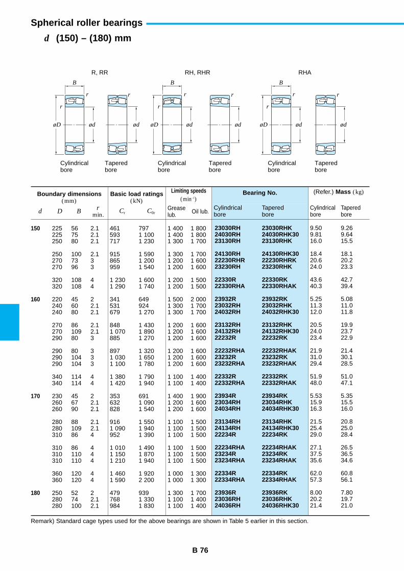
B 76
d (150) – (180) mm
Spherical roller bearings
23030RH 23030RHK24030RH 24030RHK3023130RH 23130RHK
24130RH 24130RHK3022230RHR 22230RHRK23230RH 23230RHK
22330R 22330RK22330RHA 22330RHAK
23932R 23932RK23032RH 23032RHK24032RH 24032RHK30
23132RH 23132RHK24132RH 24132RHK3022232R 22232RK
22232RHA 22232RHAK23232R 23232RK23232RHA 23232RHAK
22332R 22332RK22332RHA 22332RHAK
23934R 23934RK23034RH 23034RHK24034RH 24034RHK30
23134RH 23134RHK24134RH 24134RHK3022234R 22234RK
22234RHA 22234RHAK23234R 23234RK23234RHA 23234RHAK
22334R 22334RK22334RHA 22334RHAK
23936R 23936RK23036RH 23036RHK24036RH 24036RHK30
Bearing No.
Cylindricalbore
Taperedbore
Boundary dimensions(mm)
Basic load ratings(kN)
Limiting speeds(min–1)
d D Br
min.Cr C0r
Greaselub. Oil lub.
150
160
170
180
225 56 2.1 461 797 1 400 1 800225 75 2.1 593 1 100 1 400 1 800250 80 2.1 717 1 230 1 300 1 700
250 100 2.1 915 1 590 1 300 1 700270 73 3 865 1 200 1 200 1 600270 96 3 959 1 540 1 200 1 600
320 108 4 1 230 1 600 1 200 1 500320 108 4 1 290 1 740 1 200 1 500
220 45 2 341 649 1 500 2 000240 60 2.1 531 924 1 300 1 700240 80 2.1 679 1 270 1 300 1 700
270 86 2.1 848 1 430 1 200 1 600270 109 2.1 1 070 1 890 1 200 1 600290 80 3 885 1 270 1 200 1 600
290 80 3 897 1 320 1 200 1 600290 104 3 1 030 1 650 1 200 1 600290 104 3 1 100 1 780 1 200 1 600
340 114 4 1 380 1 790 1 100 1 400340 114 4 1 420 1 940 1 100 1 400
230 45 2 353 691 1 400 1 900260 67 2.1 632 1 090 1 200 1 600260 90 2.1 828 1 540 1 200 1 600
280 88 2.1 916 1 550 1 100 1 500280 109 2.1 1 090 1 940 1 100 1 500310 86 4 952 1 390 1 100 1 500
310 86 4 1 010 1 490 1 100 1 500310 110 4 1 150 1 870 1 100 1 500310 110 4 1 210 1 940 1 100 1 500
360 120 4 1 460 1 920 1 000 1 300360 120 4 1 590 2 200 1 000 1 300
250 52 2 479 939 1 300 1 700280 74 2.1 768 1 330 1 100 1 400280 100 2.1 984 1 830 1 100 1 400
9.50 9.269.81 9.6416.0 15.5
18.4 18.120.6 20.224.0 23.3
43.6 42.740.3 39.4
5.25 5.0811.3 11.012.0 11.8
20.5 19.924.0 23.723.4 22.9
21.9 21.431.0 30.129.4 28.5
51.9 51.048.0 47.1
5.53 5.3515.9 15.516.3 16.0
21.5 20.825.4 25.029.0 28.4
27.1 26.537.5 36.535.6 34.6
62.0 60.857.3 56.1
8.00 7.8020.2 19.721.4 21.0
(Refer.) Mass (kg)
Cylindricalbore
Taperedbore
Remark) Standard cage types used for the above bearings are shown in Table 5 earlier in this section.
r rr
r
r
r
B B
rr
r
B
ød ødøD ød ødøD ød ødøD
Cylindricalbore
Taperedbore
R, RR RH, RHR RHA
Cylindricalbore
Taperedbore
Cylindricalbore
Taperedbore
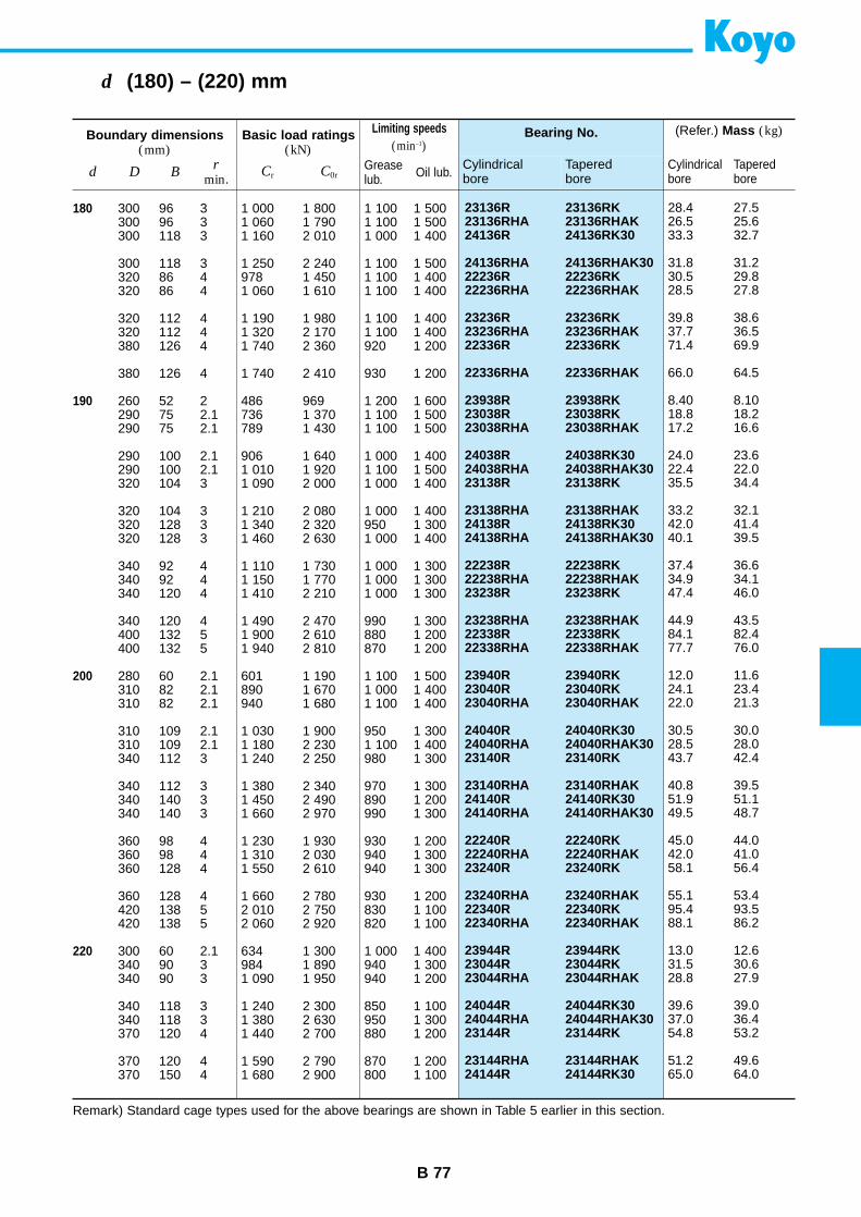
B 77
d (180) – (220) mm
23136R 23136RK23136RHA 23136RHAK24136R 24136RK30
24136RHA 24136RHAK3022236R 22236RK22236RHA 22236RHAK
23236R 23236RK23236RHA 23236RHAK22336R 22336RK
22336RHA 22336RHAK
23938R 23938RK23038R 23038RK23038RHA 23038RHAK
24038R 24038RK3024038RHA 24038RHAK3023138R 23138RK
23138RHA 23138RHAK24138R 24138RK3024138RHA 24138RHAK30
22238R 22238RK22238RHA 22238RHAK23238R 23238RK
23238RHA 23238RHAK22338R 22338RK22338RHA 22338RHAK
23940R 23940RK23040R 23040RK23040RHA 23040RHAK
24040R 24040RK3024040RHA 24040RHAK3023140R 23140RK
23140RHA 23140RHAK24140R 24140RK3024140RHA 24140RHAK30
22240R 22240RK22240RHA 22240RHAK23240R 23240RK
23240RHA 23240RHAK22340R 22340RK22340RHA 22340RHAK
23944R 23944RK23044R 23044RK23044RHA 23044RHAK
24044R 24044RK3024044RHA 24044RHAK3023144R 23144RK
23144RHA 23144RHAK24144R 24144RK30
Bearing No.
Cylindricalbore
Taperedbore
Boundary dimensions(mm)
Basic load ratings(kN)
Limiting speeds(min–1)
d D Br
min.Cr C0r
Greaselub. Oil lub.
180
190
200
220
300 96 3 1 000 1 800 1 100 1 500300 96 3 1 060 1 790 1 100 1 500300 118 3 1 160 2 010 1 000 1 400
300 118 3 1 250 2 240 1 100 1 500320 86 4 978 1 450 1 100 1 400320 86 4 1 060 1 610 1 100 1 400
320 112 4 1 190 1 980 1 100 1 400320 112 4 1 320 2 170 1 100 1 400380 126 4 1 740 2 360 920 1 200
380 126 4 1 740 2 410 930 1 200
260 52 2 486 969 1 200 1 600290 75 2.1 736 1 370 1 100 1 500290 75 2.1 789 1 430 1 100 1 500
290 100 2.1 906 1 640 1 000 1 400290 100 2.1 1 010 1 920 1 100 1 500320 104 3 1 090 2 000 1 000 1 400
320 104 3 1 210 2 080 1 000 1 400320 128 3 1 340 2 320 950 1 300320 128 3 1 460 2 630 1 000 1 400
340 92 4 1 110 1 730 1 000 1 300340 92 4 1 150 1 770 1 000 1 300340 120 4 1 410 2 210 1 000 1 300
340 120 4 1 490 2 470 990 1 300400 132 5 1 900 2 610 880 1 200400 132 5 1 940 2 810 870 1 200
280 60 2.1 601 1 190 1 100 1 500310 82 2.1 890 1 670 1 000 1 400310 82 2.1 940 1 680 1 100 1 400
310 109 2.1 1 030 1 900 950 1 300310 109 2.1 1 180 2 230 1 100 1 400340 112 3 1 240 2 250 980 1 300
340 112 3 1 380 2 340 970 1 300340 140 3 1 450 2 490 890 1 200340 140 3 1 660 2 970 990 1 300
360 98 4 1 230 1 930 930 1 200360 98 4 1 310 2 030 940 1 300360 128 4 1 550 2 610 940 1 300
360 128 4 1 660 2 780 930 1 200420 138 5 2 010 2 750 830 1 100420 138 5 2 060 2 920 820 1 100
300 60 2.1 634 1 300 1 000 1 400340 90 3 984 1 890 940 1 300340 90 3 1 090 1 950 940 1 200
340 118 3 1 240 2 300 850 1 100340 118 3 1 380 2 630 950 1 300370 120 4 1 440 2 700 880 1 200
370 120 4 1 590 2 790 870 1 200370 150 4 1 680 2 900 800 1 100
28.4 27.526.5 25.633.3 32.7
31.8 31.230.5 29.828.5 27.8
39.8 38.637.7 36.571.4 69.9
66.0 64.5
8.40 8.1018.8 18.217.2 16.6
24.0 23.622.4 22.035.5 34.4
33.2 32.142.0 41.440.1 39.5
37.4 36.634.9 34.147.4 46.0
44.9 43.584.1 82.477.7 76.0
12.0 11.624.1 23.422.0 21.3
30.5 30.028.5 28.043.7 42.4
40.8 39.551.9 51.149.5 48.7
45.0 44.042.0 41.058.1 56.4
55.1 53.495.4 93.588.1 86.2
13.0 12.631.5 30.628.8 27.9
39.6 39.037.0 36.454.8 53.2
51.2 49.665.0 64.0
(Refer.) Mass (kg)
Cylindricalbore
Taperedbore
Remark) Standard cage types used for the above bearings are shown in Table 5 earlier in this section.
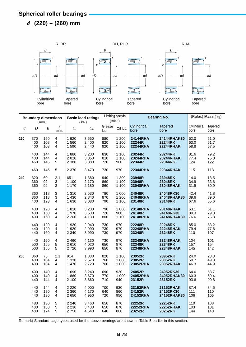
B 78
d (220) – (260) mm
Spherical roller bearings
24144RHA 24144RHAK3022244R 22244RK22244RHA 22244RHAK
23244R 23244RK23244RHA 23244RHAK22344R 22344RK
22344RHA 22344RHAK
23948R 23948RK23048R 23048RK23048RHA 23048RHAK
24048R 24048RK3024048RHA 24048RHAK3023148R 23148RK
23148RHA 23148RHAK24148R 24148RK3024148RHA 24148RHAK30
22248R 22248RK22248RHA 22248RHAK23248R 23248RK
23248RHA 23248RHAK22348R 22348RK22348RHA 22348RHAK
23952R 23952RK23052R 23052RK23052RHA 23052RHAK
24052R 24052RK3024052RHA 24052RHAK3023152R 23152RK
23152RHA 23152RHAK24152R 24152RK3024152RHA 24152RHAK30
22252R 22252RK22252RHA 22252RHAK23252R 23252RK
Bearing No.
Cylindricalbore
Taperedbore
Boundary dimensions(mm)
Basic load ratings(kN)
Limiting speeds(min–1)
d D Br
min.Cr C0r
Greaselub. Oil lub.
220
240
260
370 150 4 1 920 3 550 880 1 200400 108 4 1 560 2 400 820 1 100400 108 4 1 590 2 440 820 1 100
400 144 4 1 880 3 200 830 1 100400 144 4 2 020 3 350 810 1 100460 145 5 2 380 3 380 720 960
460 145 5 2 370 3 470 730 970
320 60 2.1 651 1 380 940 1 300360 92 3 1 100 2 170 860 1 100360 92 3 1 170 2 180 860 1 100
360 118 3 1 310 2 530 780 1 000360 118 3 1 430 2 840 870 1 200400 128 4 1 630 3 080 790 1 100
400 128 4 1 810 3 200 790 1 000400 160 4 1 970 3 500 720 960400 160 4 2 200 4 130 800 1 100
440 120 4 1 920 2 940 730 970440 120 4 1 920 2 990 730 970440 160 4 2 340 3 990 730 970
440 160 4 2 460 4 130 730 970500 155 5 2 610 4 020 650 870500 155 5 2 720 3 990 650 870
360 75 2.1 914 1 880 820 1 100400 104 4 1 330 2 570 760 1 000400 104 4 1 470 2 720 760 1 000
400 140 4 1 690 3 240 690 920400 140 4 1 860 3 670 770 1 000440 144 4 2 100 3 860 710 940
440 144 4 2 220 4 000 700 930440 180 4 2 360 4 170 640 860440 180 4 2 650 4 950 720 950
480 130 5 2 240 3 460 650 870480 130 5 2 230 3 430 650 870480 174 5 2 750 4 640 640 860
62.0 61.063.0 61.758.8 57.5
81.6 79.277.4 75.0124 122
115 113
14.0 13.534.9 33.831.9 30.9
42.4 41.839.6 39.067.6 65.6
63.1 61.180.3 79.076.6 75.3
85.0 83.279.4 77.6110 107
104 101157 154145 142
24.0 23.350.7 49.346.3 44.9
64.6 63.760.3 59.493.6 90.8
87.4 84.6111 110106 105
110 108103 101144 140
(Refer.) Mass (kg)
Cylindricalbore
Taperedbore
Remark) Standard cage types used for the above bearings are shown in Table 5 earlier in this section.
r rr
r
r
r
B B
rr
r
B
ød ødøD ød ødøD ød ødøD
Cylindricalbore
Taperedbore
R, RR RH, RHR RHA
Cylindricalbore
Taperedbore
Cylindricalbore
Taperedbore
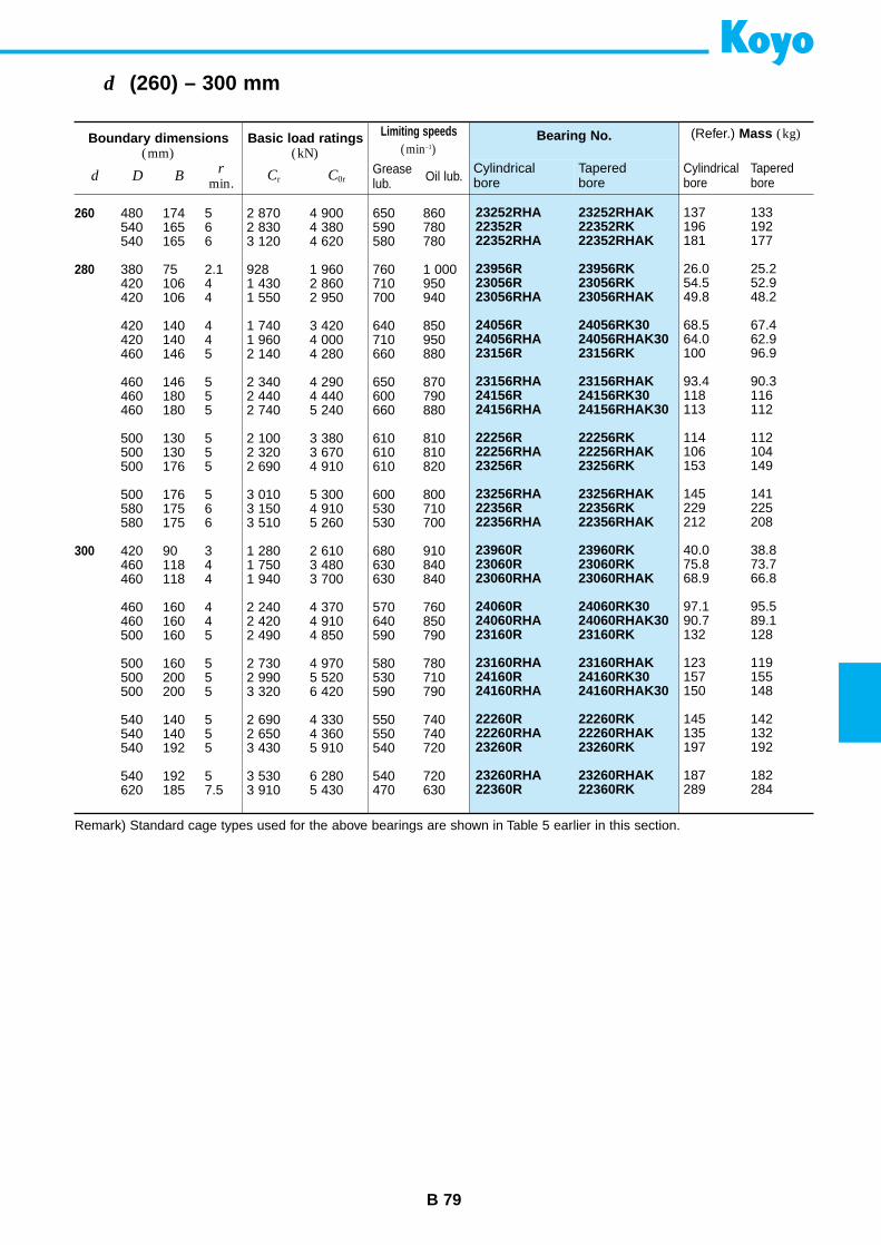
B 79
d (260) – 300 mm
23252RHA 23252RHAK22352R 22352RK22352RHA 22352RHAK
23956R 23956RK23056R 23056RK23056RHA 23056RHAK
24056R 24056RK3024056RHA 24056RHAK3023156R 23156RK
23156RHA 23156RHAK24156R 24156RK3024156RHA 24156RHAK30
22256R 22256RK22256RHA 22256RHAK23256R 23256RK
23256RHA 23256RHAK22356R 22356RK22356RHA 22356RHAK
23960R 23960RK23060R 23060RK23060RHA 23060RHAK
24060R 24060RK3024060RHA 24060RHAK3023160R 23160RK
23160RHA 23160RHAK24160R 24160RK3024160RHA 24160RHAK30
22260R 22260RK22260RHA 22260RHAK23260R 23260RK
23260RHA 23260RHAK22360R 22360RK
Bearing No.
Cylindricalbore
Taperedbore
Boundary dimensions(mm)
Basic load ratings(kN)
Limiting speeds(min–1)
d D Br
min.Cr C0r
Greaselub. Oil lub.
260
280
300
480 174 5 2 870 4 900 650 860540 165 6 2 830 4 380 590 780540 165 6 3 120 4 620 580 780
380 75 2.1 928 1 960 760 1 000420 106 4 1 430 2 860 710 950420 106 4 1 550 2 950 700 940
420 140 4 1 740 3 420 640 850420 140 4 1 960 4 000 710 950460 146 5 2 140 4 280 660 880
460 146 5 2 340 4 290 650 870460 180 5 2 440 4 440 600 790460 180 5 2 740 5 240 660 880
500 130 5 2 100 3 380 610 810500 130 5 2 320 3 670 610 810500 176 5 2 690 4 910 610 820
500 176 5 3 010 5 300 600 800580 175 6 3 150 4 910 530 710580 175 6 3 510 5 260 530 700
420 90 3 1 280 2 610 680 910460 118 4 1 750 3 480 630 840460 118 4 1 940 3 700 630 840
460 160 4 2 240 4 370 570 760460 160 4 2 420 4 910 640 850500 160 5 2 490 4 850 590 790
500 160 5 2 730 4 970 580 780500 200 5 2 990 5 520 530 710500 200 5 3 320 6 420 590 790
540 140 5 2 690 4 330 550 740540 140 5 2 650 4 360 550 740540 192 5 3 430 5 910 540 720
540 192 5 3 530 6 280 540 720620 185 7.5 3 910 5 430 470 630
137 133196 192181 177
26.0 25.254.5 52.949.8 48.2
68.5 67.464.0 62.9100 96.9
93.4 90.3118 116113 112
114 112106 104153 149
145 141229 225212 208
40.0 38.875.8 73.768.9 66.8
97.1 95.590.7 89.1132 128
123 119157 155150 148
145 142135 132197 192
187 182289 284
(Refer.) Mass (kg)
Cylindricalbore
Taperedbore
Remark) Standard cage types used for the above bearings are shown in Table 5 earlier in this section.
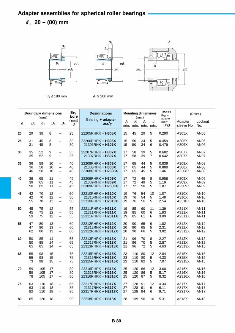
B 80
d1 20 – (80) mm
Adapter assemblies for spherical roller bearings
Boundary dimensions(mm)
Designations
Bearing + adapter ass'y
(Refer.)
d1 B1 d2 B2 B3
Brg.bore(mm)
d
MassBrg. +adapterass'y
(kg)
Mounting dimensions(mm)
Amin.
Kmin.
de
min.b
min.Adaptersleeve No.
LocknutNo.
20
25
30
35
40
45
50
55
60
65
70
75
80
22205RHRK +
22206RHRK +21306RHK +
22207RHRK +21307RHK +
22208RHRK +21308RHK +
22308RHRK +
22209RHRK +21309RHK +
22309RHRK +
22210RHRK +21310RHK +
22310RHRK +
22211RHRK +21311RHK +
22311RHRK +
22212RHRK +21312RHK +
22312RHRK +
22213RHRK +21313RHK +
22313RHRK +
22215RHRK +21315RHK +
22315RHRK +
22216RHRK +21316RHK +
22316RHRK +
22217RHRK +21317RHK +
22317RHRK +
22218RHRK +
H305X
H306XH306X
H307XH307X
H308XH308XH2308X
H309XH309XH2309X
H310XH310XH2310X
H311XH311XH2311X
H312XH312XH2312X
H313XH313XH2313X
H315XH315XH2315X
H316XH316XH2316X
H317XH317XH2317X
H318X
29 38 8 – 25
31 45 8 – 3031 45 8 – 30
35 52 9 – 3535 52 9 – 35
36 58 10 – 4036 58 10 – 4046 58 10 – 40
39 65 11 – 4539 65 11 – 4550 65 11 – 45
42 70 12 – 5042 70 12 – 5055 70 12 – 50
45 75 12 – 5545 75 12 – 5559 75 12 – 55
47 80 13 – 6047 80 13 – 6062 80 13 – 60
50 85 14 – 6550 85 14 – 6565 85 14 – 65
55 98 15 – 7555 98 15 – 7573 98 15 – 75
59 105 17 – 8059 105 17 – 8078 105 17 – 80
63 110 18 – 8563 110 18 – 8582 110 18 – 85
65 120 18 – 90
15 45 29 5 0.290 A305X AN05
15 50 34 5 0.459 A306X AN0615 50 34 6 0.479 A306X AN06
17 58 39 5 0.682 A307X AN0717 58 39 7 0.642 A307X AN07
17 65 44 5 0.839 A308X AN0817 65 44 5 0.888 A308X AN0817 65 45 5 1.46 A2308X AN08
17 72 49 8 0.958 A309X AN0917 72 49 5 1.19 A309X AN0917 72 50 5 1.87 A2309X AN09
19 76 54 10 1.07 A310X AN1019 76 54 5 1.48 A310X AN1019 76 56 5 2.54 A2310X AN10
19 85 60 11 1.39 A311X AN1119 85 60 6 1.93 A311X AN1119 85 61 6 3.09 A2311X AN11
20 90 65 9 1.82 A312X AN1220 90 65 5 2.31 A312X AN1220 90 66 5 3.82 A2312X AN12
21 96 70 8 2.27 A313X AN1321 96 70 5 2.87 A313X AN1321 96 72 5 4.63 A2313X AN13
23 110 80 12 2.84 A315X AN1523 110 80 5 4.33 A315X AN1523 110 82 5 7.07 A2315X AN15
25 120 86 12 3.60 A316X AN1625 120 86 5 5.17 A316X AN1625 120 87 5 8.32 A2316X AN16
27 128 91 12 4.34 A317X AN1727 128 91 6 6.11 A317X AN1727 128 94 6 9.71 A2317X AN17
28 139 96 10 5.31 A318X AN18
B2B2
B3
bB1 B1
A
ød1
ød2
ød1 øde øK
ød2
d1 ≤ 180 mm d1 ≥ 200 mm
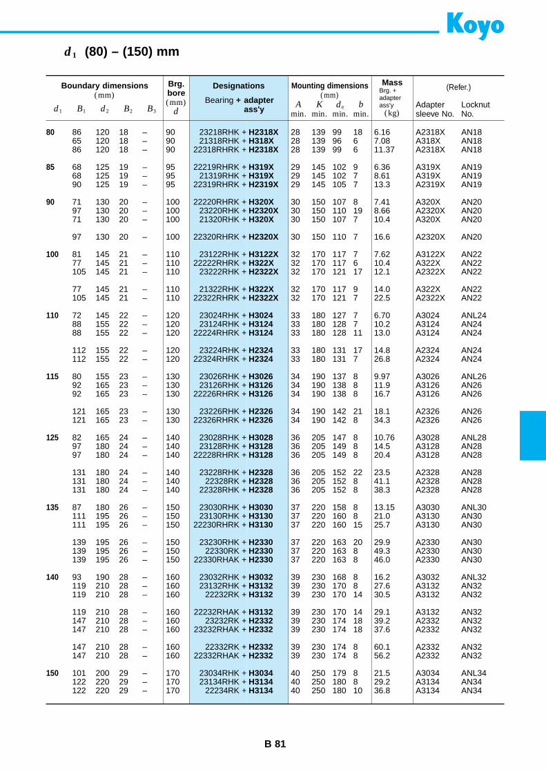
B 81
d1 (80) – (150) mm
Boundary dimensions(mm)
Designations
Bearing + adapter ass'y
(Refer.)
d1 B1 d2 B2 B3
Brg.bore(mm)
d
MassBrg. +adapterass'y
(kg)
Mounting dimensions(mm)
Amin.
Kmin.
de
min.b
min.Adaptersleeve No.
LocknutNo.
80
85
90
100
110
115
125
135
140
150
23218RHK +21318RHK +
22318RHRK +
22219RHRK +21319RHK +
22319RHRK +
22220RHRK +23220RHK +21320RHK +
22320RHRK +
23122RHK +22222RHRK +
23222RHK +
21322RHK +22322RHRK +
23024RHK +23124RHK +
22224RHRK +
23224RHK +22324RHRK +
23026RHK +23126RHK +
22226RHRK +
23226RHK +22326RHRK +
23028RHK +23128RHK +
22228RHRK +
23228RHK +22328RK +
22328RHK +
23030RHK +23130RHK +
22230RHRK +
23230RHK +22330RK +
22330RHAK +
23032RHK +23132RHK +
22232RK +
22232RHAK +23232RK +
23232RHAK +
22332RK +22332RHAK +
23034RHK +23134RHK +
22234RK +
H2318XH318XH2318X
H319XH319XH2319X
H320XH2320XH320X
H2320X
H3122XH322XH2322X
H322XH2322X
H3024H3124H3124
H2324H2324
H3026H3126H3126
H2326H2326
H3028H3128H3128
H2328H2328H2328
H3030H3130H3130
H2330H2330H2330
H3032H3132H3132
H3132H2332H2332
H2332H2332
H3034H3134H3134
86 120 18 – 9065 120 18 – 9086 120 18 – 90
68 125 19 – 9568 125 19 – 9590 125 19 – 95
71 130 20 – 10097 130 20 – 10071 130 20 – 100
97 130 20 – 100
81 145 21 – 11077 145 21 – 110105 145 21 – 110
77 145 21 – 110105 145 21 – 110
72 145 22 – 12088 155 22 – 12088 155 22 – 120
112 155 22 – 120112 155 22 – 120
80 155 23 – 13092 165 23 – 13092 165 23 – 130
121 165 23 – 130121 165 23 – 130
82 165 24 – 14097 180 24 – 14097 180 24 – 140
131 180 24 – 140131 180 24 – 140131 180 24 – 140
87 180 26 – 150111 195 26 – 150111 195 26 – 150
139 195 26 – 150139 195 26 – 150139 195 26 – 150
93 190 28 – 160119 210 28 – 160119 210 28 – 160
119 210 28 – 160147 210 28 – 160147 210 28 – 160
147 210 28 – 160147 210 28 – 160
101 200 29 – 170122 220 29 – 170122 220 29 – 170
28 139 99 18 6.16 A2318X AN1828 139 96 6 7.08 A318X AN1828 139 99 6 11.37 A2318X AN18
29 145 102 9 6.36 A319X AN1929 145 102 7 8.61 A319X AN1929 145 105 7 13.3 A2319X AN19
30 150 107 8 7.41 A320X AN2030 150 110 19 8.66 A2320X AN2030 150 107 7 10.4 A320X AN20
30 150 110 7 16.6 A2320X AN20
32 170 117 7 7.62 A3122X AN2232 170 117 6 10.4 A322X AN2232 170 121 17 12.1 A2322X AN22
32 170 117 9 14.0 A322X AN2232 170 121 7 22.5 A2322X AN22
33 180 127 7 6.70 A3024 ANL2433 180 128 7 10.2 A3124 AN2433 180 128 11 13.0 A3124 AN24
33 180 131 17 14.8 A2324 AN2433 180 131 7 26.8 A2324 AN24
34 190 137 8 9.97 A3026 ANL2634 190 138 8 11.9 A3126 AN2634 190 138 8 16.7 A3126 AN26
34 190 142 21 18.1 A2326 AN2634 190 142 8 34.3 A2326 AN26
36 205 147 8 10.76 A3028 ANL2836 205 149 8 14.5 A3128 AN2836 205 149 8 20.4 A3128 AN28
36 205 152 22 23.5 A2328 AN2836 205 152 8 41.1 A2328 AN2836 205 152 8 38.3 A2328 AN28
37 220 158 8 13.15 A3030 ANL3037 220 160 8 21.0 A3130 AN3037 220 160 15 25.7 A3130 AN30
37 220 163 20 29.9 A2330 AN3037 220 163 8 49.3 A2330 AN3037 220 163 8 46.0 A2330 AN30
39 230 168 8 16.2 A3032 ANL3239 230 170 8 27.6 A3132 AN3239 230 170 14 30.5 A3132 AN32
39 230 170 14 29.1 A3132 AN3239 230 174 18 39.2 A2332 AN3239 230 174 18 37.6 A2332 AN32
39 230 174 8 60.1 A2332 AN3239 230 174 8 56.2 A2332 AN32
40 250 179 8 21.5 A3034 ANL3440 250 180 8 29.2 A3134 AN3440 250 180 10 36.8 A3134 AN34
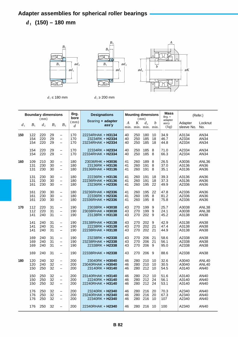
B 82
d1 (150) – 180 mm
Adapter assemblies for spherical roller bearings
Boundary dimensions(mm)
Designations
Bearing + adapter ass'y
(Refer.)
d1 B1 d2 B2 B3
Brg.bore(mm)
d
MassBrg. +adapterass'y
(kg)
Mounting dimensions(mm)
Amin.
Kmin.
de
min.b
min.Adaptersleeve No.
LocknutNo.
150
160
170
180
22234RHAK +23234RK +
23234RHAK +
22334RK +22334RHAK +
23036RHK +23136RK +
23136RHAK +
22236RK +22236RHAK +
23236RK +
23236RHAK +22336RK +
22336RHAK +
23038RK +23038RHAK +
23138RK +
23138RHAK +22238RK +
22238RHAK +
23238RK +23238RHAK +
22338RK +
22338RHAK +
23040RK +23040RHAK +
23140RK +
23140RHAK +22240RK +
22240RHAK +
23240RK +23240RHAK +
22340RK +
22340RHAK +
H3134H2334H2334
H2334H2334
H3036H3136H3136
H3136H3136H2336
H2336H2336H2336
H3038H3038H3138
H3138H3138H3138
H2338H2338H2338
H2338
H3040H3040H3140
H3140H3140H3140
H2340H2340H2340
H2340
122 220 29 – 170154 220 29 – 170154 220 29 – 170
154 220 29 – 170154 220 29 – 170
109 210 30 – 180131 230 30 – 180131 230 30 – 180
131 230 30 – 180131 230 30 – 180161 230 30 – 180
161 230 30 – 180161 230 30 – 180161 230 30 – 180
112 220 31 – 190112 220 31 – 190141 240 31 – 190
141 240 31 – 190141 240 31 – 190141 240 31 – 190
169 240 31 – 190169 240 31 – 190169 240 31 – 190
169 240 31 – 190
120 240 32 – 200120 240 32 – 200150 250 32 – 200
150 250 32 – 200150 250 32 – 200150 250 32 – 200
176 250 32 – 200176 250 32 – 200176 250 32 – 200
176 250 32 – 200
40 250 180 10 34.9 A3134 AN3440 250 185 18 46.7 A2334 AN3440 250 185 18 44.8 A2334 AN34
40 250 185 8 71.0 A2334 AN3440 250 185 8 66.3 A2334 AN34
41 260 189 8 26.5 A3036 ANL3641 260 191 8 37.0 A3136 AN3641 260 191 8 35.1 A3136 AN36
41 260 191 18 39.3 A3136 AN3641 260 191 18 37.3 A3136 AN3641 260 195 22 49.9 A2336 AN36
41 260 195 22 47.8 A2336 AN3641 260 195 8 81.2 A2336 AN3641 260 195 8 75.8 A2336 AN36
43 270 199 9 25.7 A3038 ANL3843 270 199 9 24.1 A3038 ANL3843 270 202 9 45.2 A3138 AN38
43 270 202 9 42.9 A3138 AN3843 270 202 21 47.4 A3138 AN3843 270 202 21 44.9 A3138 AN38
43 270 206 21 58.6 A2338 AN3843 270 206 21 56.1 A2338 AN3843 270 206 9 95.0 A2338 AN38
43 270 206 9 88.6 A2338 AN38
46 280 210 10 32.6 A3040 ANL4046 280 210 10 30.5 A3040 ANL4046 280 212 10 54.5 A3140 AN40
46 280 212 10 51.6 A3140 AN4046 280 212 24 56.1 A3140 AN4046 280 212 24 53.1 A3140 AN40
46 280 216 20 70.3 A2340 AN4046 280 216 20 67.3 A2340 AN4046 280 216 10 107 A2340 AN40
46 280 216 10 100 A2340 AN40
B2
B3
bB1 B1
A
ød1
ød2
ød1 øde øK
ød2
d1 ≤ 180 mm d1 ≥ 200 mm
B2
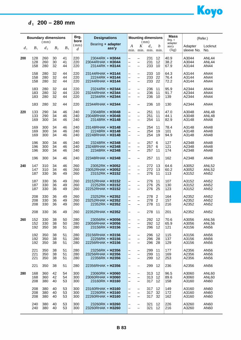
B 83
d1 200 – 280 mm
Boundary dimensions(mm)
Designations
Bearing + adapter ass'y
(Refer.)
d1 B1 d2 B2 B3
Brg.bore(mm)
d
MassBrg. +adapterass'y
(kg)
Mounting dimensions(mm)
Amin.
Kmin.
de
min.b
min.Adaptersleeve No.
LocknutNo.
200
220
240
260
280
23044RK +23044RHAK +
23144RK +
23144RHAK +22244RK +
22244RHAK +
23244RK +23244RHAK +
22344RK +
22344RHAK +
23048RK +23048RHAK +
23148RK +
23148RHAK +22248RK +
22248RHAK +
23248RK +23248RHAK +
22348RK +
22348RHAK +
23052RK +23052RHAK +
23152RK +
23152RHAK +22252RK +
22252RHAK +
23252RK +23252RHAK +
22352RK +
22352RHAK +
23056RK +23056RHAK +
23156RK +
23156RHAK +22256RK +
22256RHAK +
23256RK +23256RHAK +
22356RK +
22356RHAK +
23060RK +23060RHAK +
23160RK +
23160RHAK +22260RK +
22260RHAK +
23260RK +23260RHAK +
H3044H3044H3144
H3144H3144H3144
H2344H2344H2344
H2344
H3048H3048H3148
H3148H3148H3148
H2348H2348H2348
H2348
H3052H3052H3152
H3152H3152H3152
H2352H2352H2352
H2352
H3056H3056H3156
H3156H3156H3156
H2356H2356H2356
H2356
H3060H3060H3160
H3160H3160H3160
H3260H3260
128 260 30 41 220128 260 30 41 220158 280 32 44 220
158 280 32 44 220158 280 32 44 220158 280 32 44 220
183 280 32 44 220183 280 32 44 220183 280 32 44 220
183 280 32 44 220
133 290 34 46 240133 290 34 46 240169 300 34 46 240
169 300 34 46 240169 300 34 46 240169 300 34 46 240
196 300 34 46 240196 300 34 46 240196 300 34 46 240
196 300 34 46 240
147 310 34 46 260147 310 34 46 260187 330 36 49 260
187 330 36 49 260187 330 36 49 260187 330 36 49 260
208 330 36 49 260208 330 36 49 260208 330 36 49 260
208 330 36 49 260
152 330 38 50 280152 330 38 50 280192 350 38 51 280
192 350 38 51 280192 350 38 51 280192 350 38 51 280
221 350 38 51 280221 350 38 51 280221 350 38 51 280
221 350 38 51 280
168 360 42 54 300168 360 42 54 300208 380 40 53 300
208 380 40 53 300208 380 40 53 300208 380 40 53 300
240 380 40 53 300240 380 40 53 300
– – 231 12 40.9 A3044 ANL44– – 231 12 38.2 A3044 ANL44– – 233 10 67.9 A3144 AN44
– – 233 10 64.3 A3144 AN44– – 233 22 76.4 A3144 AN44– – 233 22 72.2 A3144 AN44
– – 236 11 95.9 A2344 AN44– – 236 11 91.7 A2344 AN44– – 236 10 139 A2344 AN44
– – 236 10 130 A2344 AN44
– – 251 11 47.0 A3048 ANL48– – 251 11 44.1 A3048 ANL48– – 254 11 82.9 A3148 AN48
– – 254 11 78.4 A3148 AN48– – 254 19 101 A3148 AN48– – 254 19 94.9 A3148 AN48
– – 257 6 127 A2348 AN48– – 257 6 121 A2348 AN48– – 257 11 174 A2348 AN48
– – 257 11 162 A2348 AN48
– – 272 13 64.6 A3052 ANL52– – 272 13 60.2 A3052 ANL52– – 276 11 113 A3152 AN52
– – 276 11 107 A3152 AN52– – 276 25 130 A3152 AN52– – 276 25 123 A3152 AN52
– – 278 2 164 A2352 AN52– – 278 2 157 A2352 AN52– – 278 11 216 A2352 AN52
– – 278 11 201 A2352 AN52
– – 292 12 70.6 A3056 ANL56– – 292 12 65.9 A3056 ANL56– – 296 12 121 A3156 AN56
– – 296 12 115 A3156 AN56– – 296 28 137 A3156 AN56– – 296 28 129 A3156 AN56
– – 299 11 177 A2356 AN56– – 299 11 169 A2356 AN56– – 299 12 253 A2356 AN56
– – 299 12 236 A2356 AN56
– – 313 12 96.5 A3060 ANL60– – 313 12 89.6 A3060 ANL60– – 317 12 158 A3160 AN60
– – 317 12 149 A3160 AN60– – 317 32 172 A3160 AN60– – 317 32 162 A3160 AN60
– – 321 12 226 A3260 AN60– – 321 12 216 A3260 AN60
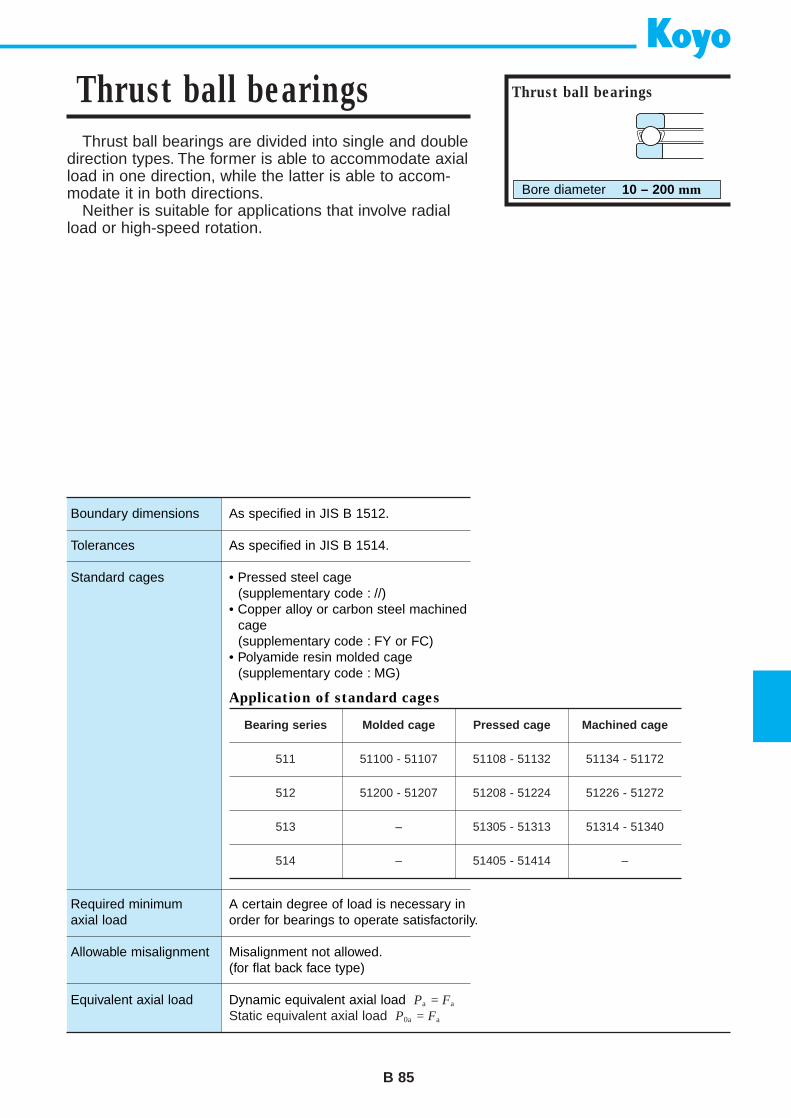
Thrust ball bearings are divided into single and doubledirection types. The former is able to accommodate axialload in one direction, while the latter is able to accom-modate it in both directions.
Neither is suitable for applications that involve radialload or high-speed rotation.
B 85
Thrust ball bearings Thrust ball bearings
Bore diameter 10 – 200 mm
Boundary dimensions
Tolerances
Standard cages
Required minimum axial load
Allowable misalignment
Equivalent axial load
As specified in JIS B 1512.
As specified in JIS B 1514.
• Pressed steel cage(supplementary code : //)
• Copper alloy or carbon steel machinedcage(supplementary code : FY or FC)
• Polyamide resin molded cage(supplementary code : MG)
Application of standard cages
A certain degree of load is necessary inorder for bearings to operate satisfactorily.
Misalignment not allowed.(for flat back face type)
Dynamic equivalent axial load Pa = Fa
Static equivalent axial load P0a = Fa
Bearing series Molded cage Pressed cage Machined cage
511
512
513
514
51100 - 51107
51200 - 51207
–
–
51108 - 51132
51208 - 51224
51305 - 51313
51405 - 51414
51134 - 51172
51226 - 51272
51314 - 51340
–
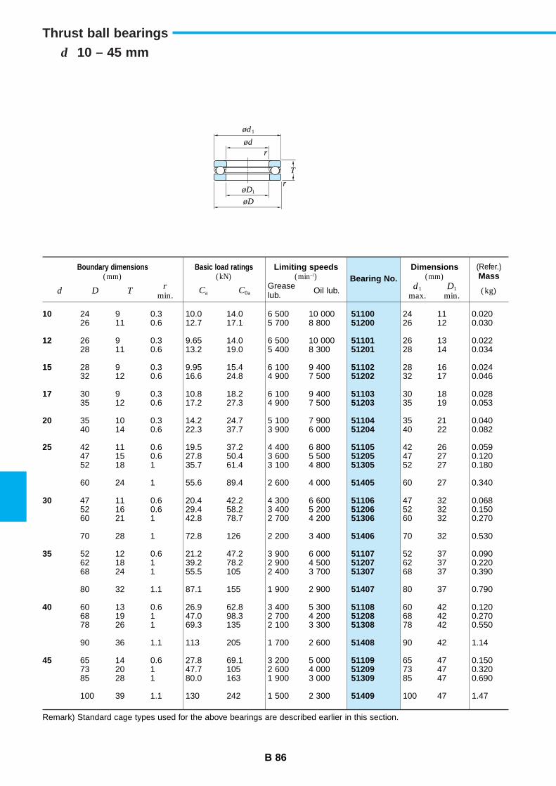
Bearing No.
5110051200
5110151201
5110251202
5110351203
5110451204
511055120551305
51405
511065120651306
51406
511075120751307
51407
511085120851308
51408
511095120951309
51409
B 86
d 10 – 45 mmThrust ball bearings
Boundary dimensions(mm)
Basic load ratings(kN)
(Refer.)Mass
d D Tr
min.Ca C0a (kg)
10
12
15
17
20
25
30
35
40
45
24 9 0.3 10.0 14.0 6 500 10 00026 11 0.6 12.7 17.1 5 700 8 800
26 9 0.3 9.65 14.0 6 500 10 00028 11 0.6 13.2 19.0 5 400 8 300
28 9 0.3 9.95 15.4 6 100 9 40032 12 0.6 16.6 24.8 4 900 7 500
30 9 0.3 10.8 18.2 6 100 9 40035 12 0.6 17.2 27.3 4 900 7 500
35 10 0.3 14.2 24.7 5 100 7 90040 14 0.6 22.3 37.7 3 900 6 000
42 11 0.6 19.5 37.2 4 400 6 80047 15 0.6 27.8 50.4 3 600 5 50052 18 1 35.7 61.4 3 100 4 800
60 24 1 55.6 89.4 2 600 4 000
47 11 0.6 20.4 42.2 4 300 6 60052 16 0.6 29.4 58.2 3 400 5 20060 21 1 42.8 78.7 2 700 4 200
70 28 1 72.8 126 2 200 3 400
52 12 0.6 21.2 47.2 3 900 6 00062 18 1 39.2 78.2 2 900 4 50068 24 1 55.5 105 2 400 3 700
80 32 1.1 87.1 155 1 900 2 900
60 13 0.6 26.9 62.8 3 400 5 30068 19 1 47.0 98.3 2 700 4 20078 26 1 69.3 135 2 100 3 300
90 36 1.1 113 205 1 700 2 600
65 14 0.6 27.8 69.1 3 200 5 00073 20 1 47.7 105 2 600 4 00085 28 1 80.0 163 1 900 3 000
100 39 1.1 130 242 1 500 2 300
Dimensions(mm)
d1
max.D1
min.
24 11 0.02026 12 0.030
26 13 0.02228 14 0.034
28 16 0.02432 17 0.046
30 18 0.02835 19 0.053
35 21 0.04040 22 0.082
42 26 0.05947 27 0.12052 27 0.180
60 27 0.340
47 32 0.06852 32 0.15060 32 0.270
70 32 0.530
52 37 0.09062 37 0.22068 37 0.390
80 37 0.790
60 42 0.12068 42 0.27078 42 0.550
90 42 1.14
65 47 0.15073 47 0.32085 47 0.690
100 47 1.47
Limiting speeds(min–1)
Greaselub. Oil lub.
Remark) Standard cage types used for the above bearings are described earlier in this section.
ød1
ød
øD1
øD
T
r
r
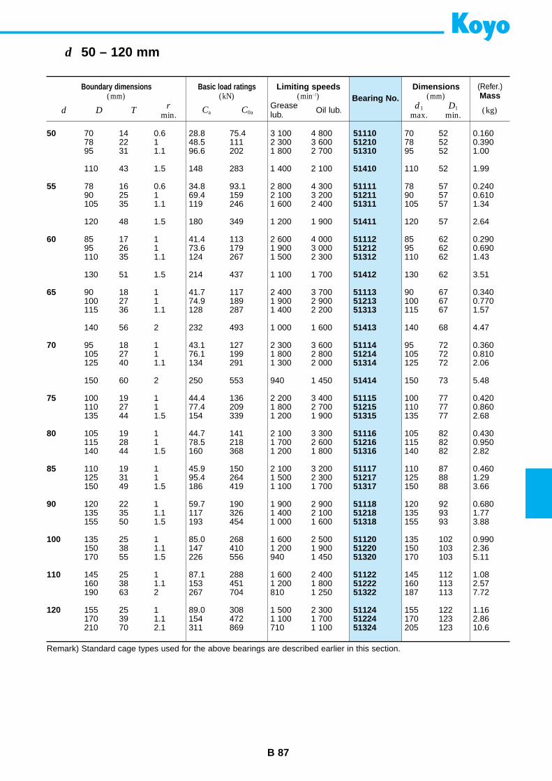
B 87
d 50 – 120 mm
Remark) Standard cage types used for the above bearings are described earlier in this section.
Bearing No.
511105121051310
51410
511115121151311
51411
511125121251312
51412
511135121351313
51413
511145121451314
51414
511155121551315
511165121651316
511175121751317
511185121851318
511205122051320
511225122251322
511245122451324
Boundary dimensions(mm)
Basic load ratings(kN)
(Refer.)Mass
d D Tr
min.Ca C0a (kg)
50
55
60
65
70
75
80
85
90
100
110
120
70 14 0.6 28.8 75.4 3 100 4 80078 22 1 48.5 111 2 300 3 60095 31 1.1 96.6 202 1 800 2 700
110 43 1.5 148 283 1 400 2 100
78 16 0.6 34.8 93.1 2 800 4 30090 25 1 69.4 159 2 100 3 200105 35 1.1 119 246 1 600 2 400
120 48 1.5 180 349 1 200 1 900
85 17 1 41.4 113 2 600 4 00095 26 1 73.6 179 1 900 3 000110 35 1.1 124 267 1 500 2 300
130 51 1.5 214 437 1 100 1 700
90 18 1 41.7 117 2 400 3 700100 27 1 74.9 189 1 900 2 900115 36 1.1 128 287 1 400 2 200
140 56 2 232 493 1 000 1 600
95 18 1 43.1 127 2 300 3 600105 27 1 76.1 199 1 800 2 800125 40 1.1 134 291 1 300 2 000
150 60 2 250 553 940 1 450
100 19 1 44.4 136 2 200 3 400110 27 1 77.4 209 1 800 2 700135 44 1.5 154 339 1 200 1 900
105 19 1 44.7 141 2 100 3 300115 28 1 78.5 218 1 700 2 600140 44 1.5 160 368 1 200 1 800
110 19 1 45.9 150 2 100 3 200125 31 1 95.4 264 1 500 2 300150 49 1.5 186 419 1 100 1 700
120 22 1 59.7 190 1 900 2 900135 35 1.1 117 326 1 400 2 100155 50 1.5 193 454 1 000 1 600
135 25 1 85.0 268 1 600 2 500150 38 1.1 147 410 1 200 1 900170 55 1.5 226 556 940 1 450
145 25 1 87.1 288 1 600 2 400160 38 1.1 153 451 1 200 1 800190 63 2 267 704 810 1 250
155 25 1 89.0 308 1 500 2 300170 39 1.1 154 472 1 100 1 700210 70 2.1 311 869 710 1 100
Dimensions(mm)
d1
max.D1
min.
70 52 0.16078 52 0.39095 52 1.00
110 52 1.99
78 57 0.24090 57 0.610105 57 1.34
120 57 2.64
85 62 0.29095 62 0.690110 62 1.43
130 62 3.51
90 67 0.340100 67 0.770115 67 1.57
140 68 4.47
95 72 0.360105 72 0.810125 72 2.06
150 73 5.48
100 77 0.420110 77 0.860135 77 2.68
105 82 0.430115 82 0.950140 82 2.82
110 87 0.460125 88 1.29150 88 3.66
120 92 0.680135 93 1.77155 93 3.88
135 102 0.990150 103 2.36170 103 5.11
145 112 1.08160 113 2.57187 113 7.72
155 122 1.16170 123 2.86205 123 10.6
Limiting speeds(min–1)
Greaselub. Oil lub.
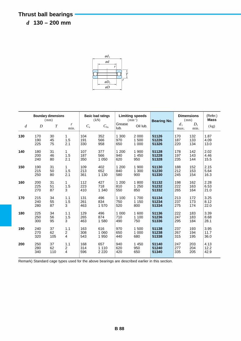
B 88
d 130 – 200 mmThrust ball bearings
Bearing No.
511265122651326
511285122851328
511305123051330
511325123251332
511345123451334
511365123651336
511385123851338
511405124051340
Boundary dimensions(mm)
Basic load ratings(kN)
(Refer.)Mass
d D Tr
min.Ca C0a (kg)
130
140
150
160
170
180
190
200
170 30 1 104 352 1 300 2 000190 45 1.5 191 566 970 1 500225 75 2.1 330 958 650 1 000
180 31 1 107 377 1 200 1 900200 46 1.5 187 566 940 1 450240 80 2.1 350 1 050 620 950
190 31 1 109 402 1 200 1 900215 50 1.5 213 652 840 1 300250 80 2.1 361 1 130 580 900
200 31 1 112 427 1 200 1 800225 51 1.5 223 718 810 1 250270 87 3 410 1 340 550 850
215 34 1.1 131 496 1 100 1 700240 55 1.5 261 834 750 1 150280 87 3 463 1 570 520 800
225 34 1.1 129 496 1 000 1 600250 56 1.5 265 874 710 1 100300 95 3 463 1 580 490 750
240 37 1.1 163 616 970 1 500270 62 2 308 1 060 650 1 000320 105 4 543 1 950 440 680
250 37 1.1 168 657 940 1 450280 62 2 314 1 110 620 950340 110 4 596 2 220 420 650
Dimensions(mm)
d1
max.D1
min.
170 132 1.87187 133 4.09220 134 13.0
178 142 2.02197 143 4.46235 144 15.5
188 152 2.15212 153 5.64245 154 16.3
198 162 2.28222 163 6.53265 164 21.0
213 172 3.25237 173 8.12275 174 22.0
222 183 3.39247 183 8.68295 184 28.1
237 193 3.95267 194 11.7315 195 36.0
247 203 4.13277 204 12.2335 205 42.9
Limiting speeds(min–1)
Greaselub. Oil lub.
Remark) Standard cage types used for the above bearings are described earlier in this section.
ød1
ød
øD1
øD
T
r
r

B 89
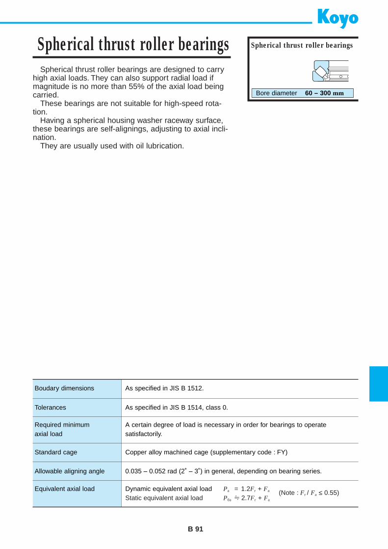
Spherical thrust roller bearings are designed to carryhigh axial loads. They can also support radial load ifmagnitude is no more than 55% of the axial load beingcarried.
These bearings are not suitable for high-speed rota-tion.
Having a spherical housing washer raceway surface,these bearings are self-alignings, adjusting to axial incli-nation.
They are usually used with oil lubrication.
B 91
Spherical thrust roller bearings Spherical thrust roller bearings
Bore diameter 60 – 300 mm
Boudary dimensions
Tolerances
Required minimumaxial load
Standard cage
Allowable aligning angle
Equivalent axial load
As specified in JIS B 1512.
As specified in JIS B 1514, class 0.
A certain degree of load is necessary in order for bearings to operate satisfactorily.
Copper alloy machined cage (supplementary code : FY)
0.035 – 0.052 rad (2˚ – 3˚) in general, depending on bearing series.
Dynamic equivalent axial load Pa = 1.2Fr + Fa
Static equivalent axial load P0a ≈ 2.7Fr + Fa
(Note : Fr / Fa ≤ 0.55)
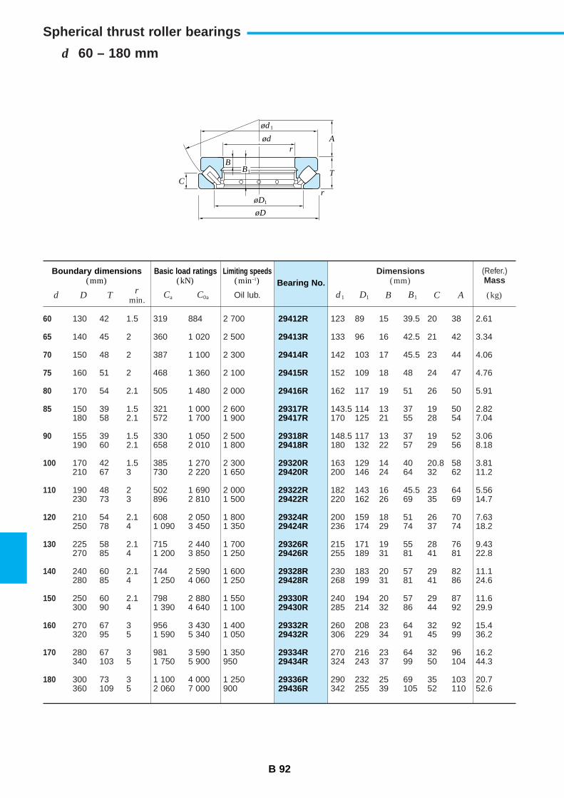
B 92
d 60 – 180 mm
Spherical thrust roller bearings
29412R
29413R
29414R
29415R
29416R
29317R29417R
29318R29418R
29320R29420R
29322R29422R
29324R29424R
29326R29426R
29328R29428R
29330R29430R
29332R29432R
29334R29434R
29336R29436R
Bearing No.Boundary dimensions
(mm)Basic load ratings
(kN)Limiting speeds
(min–1)
d D Tr
min.
Dimensions(mm)
d1 D1 B B1 C ACa C0a Oil lub.
60
65
70
75
80
85
90
100
110
120
130
140
150
160
170
180
130 42 1.5 319 884 2 700
140 45 2 360 1 020 2 500
150 48 2 387 1 100 2 300
160 51 2 468 1 360 2 100
170 54 2.1 505 1 480 2 000
150 39 1.5 321 1 000 2 600180 58 2.1 572 1 700 1 900
155 39 1.5 330 1 050 2 500190 60 2.1 658 2 010 1 800
170 42 1.5 385 1 270 2 300210 67 3 730 2 220 1 650
190 48 2 502 1 690 2 000230 73 3 896 2 810 1 500
210 54 2.1 608 2 050 1 800250 78 4 1 090 3 450 1 350
225 58 2.1 715 2 440 1 700270 85 4 1 200 3 850 1 250
240 60 2.1 744 2 590 1 600280 85 4 1 250 4 060 1 250
250 60 2.1 798 2 880 1 550300 90 4 1 390 4 640 1 100
270 67 3 956 3 430 1 400320 95 5 1 590 5 340 1 050
280 67 3 981 3 590 1 350340 103 5 1 750 5 900 950
300 73 3 1 100 4 000 1 250360 109 5 2 060 7 000 900
123 89 15 39.5 20 38 2.61
133 96 16 42.5 21 42 3.34
142 103 17 45.5 23 44 4.06
152 109 18 48 24 47 4.76
162 117 19 51 26 50 5.91
143.5 114 13 37 19 50 2.82170 125 21 55 28 54 7.04
148.5 117 13 37 19 52 3.06180 132 22 57 29 56 8.18
163 129 14 40 20.8 58 3.81200 146 24 64 32 62 11.2
182 143 16 45.5 23 64 5.56220 162 26 69 35 69 14.7
200 159 18 51 26 70 7.63236 174 29 74 37 74 18.2
215 171 19 55 28 76 9.43255 189 31 81 41 81 22.8
230 183 20 57 29 82 11.1268 199 31 81 41 86 24.6
240 194 20 57 29 87 11.6285 214 32 86 44 92 29.9
260 208 23 64 32 92 15.4306 229 34 91 45 99 36.2
270 216 23 64 32 96 16.2324 243 37 99 50 104 44.3
290 232 25 69 35 103 20.7342 255 39 105 52 110 52.6
(Refer.)Mass
(kg)
ød1
ød
øD1
øD
T
A
BB1
C
r
r
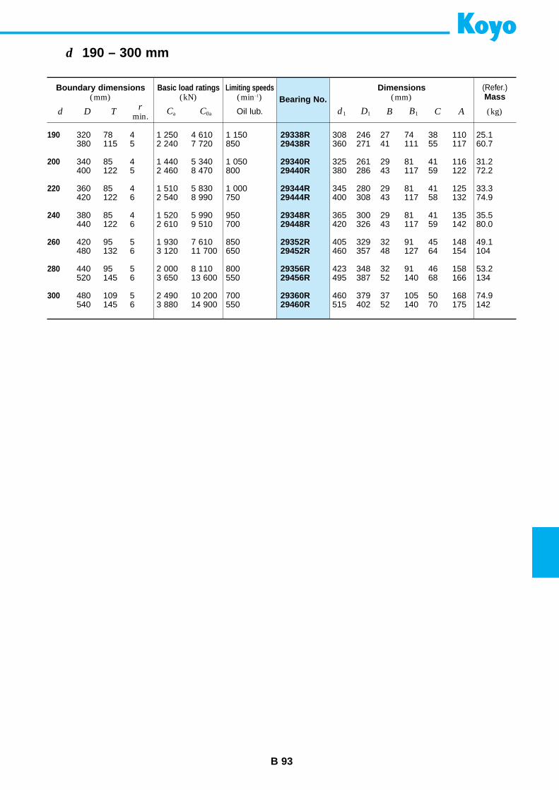
B 93
d 190 – 300 mm
29338R29438R
29340R29440R
29344R29444R
29348R29448R
29352R29452R
29356R29456R
29360R29460R
Bearing No.Boundary dimensions
(mm)Basic load ratings
(kN)Limiting speeds
(min–1)
d D Tr
min.
Dimensions(mm)
d1 D1 B B1 C ACa C0a Oil lub.
190
200
220
240
260
280
300
320 78 4 1 250 4 610 1 150380 115 5 2 240 7 720 850
340 85 4 1 440 5 340 1 050400 122 5 2 460 8 470 800
360 85 4 1 510 5 830 1 000420 122 6 2 540 8 990 750
380 85 4 1 520 5 990 950440 122 6 2 610 9 510 700
420 95 5 1 930 7 610 850480 132 6 3 120 11 700 650
440 95 5 2 000 8 110 800520 145 6 3 650 13 600 550
480 109 5 2 490 10 200 700540 145 6 3 880 14 900 550
308 246 27 74 38 110 25.1360 271 41 111 55 117 60.7
325 261 29 81 41 116 31.2380 286 43 117 59 122 72.2
345 280 29 81 41 125 33.3400 308 43 117 58 132 74.9
365 300 29 81 41 135 35.5420 326 43 117 59 142 80.0
405 329 32 91 45 148 49.1460 357 48 127 64 154 104
423 348 32 91 46 158 53.2495 387 52 140 68 166 134
460 379 37 105 50 168 74.9515 402 52 140 70 175 142
(Refer.)Mass
(kg)
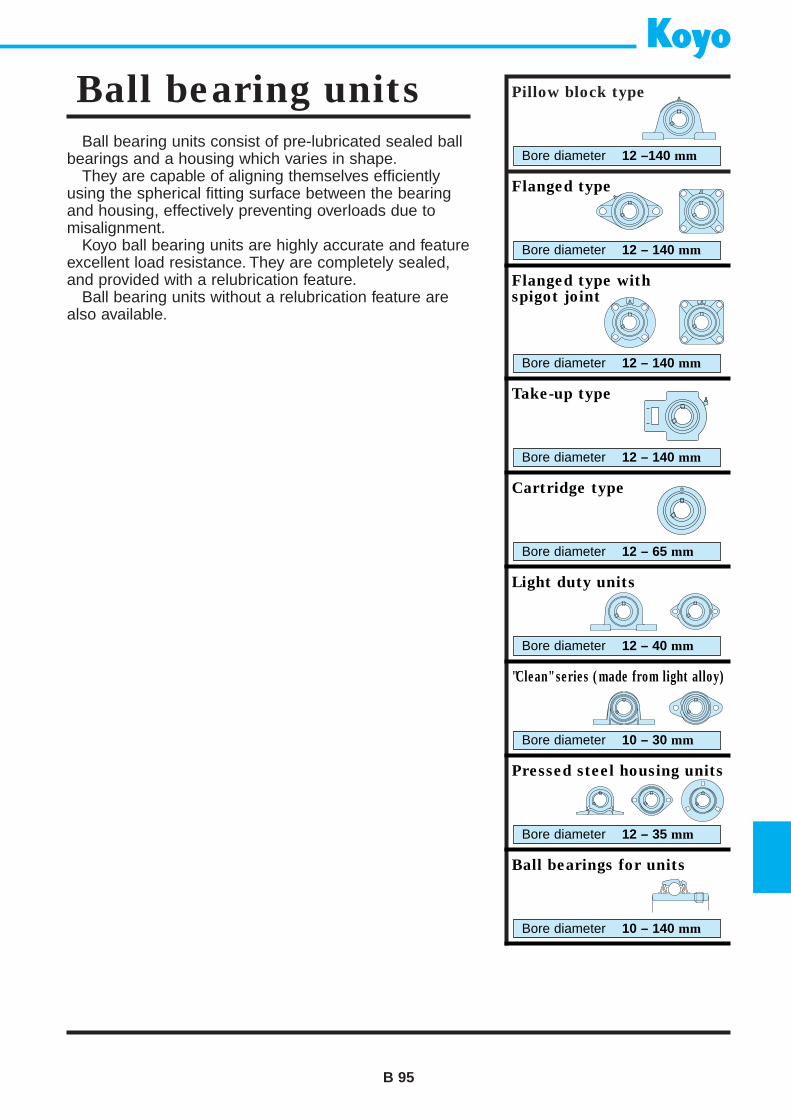
Ball bearing units consist of pre-lubricated sealed ballbearings and a housing which varies in shape.
They are capable of aligning themselves efficientlyusing the spherical fitting surface between the bearingand housing, effectively preventing overloads due tomisalignment.
Koyo ball bearing units are highly accurate and featureexcellent load resistance. They are completely sealed,and provided with a relubrication feature.
Ball bearing units without a relubrication feature arealso available.
B 95
Ball bearing units Pillow block type
Bore diameter 12 –140 mm
Flanged type
Bore diameter 12 – 140 mm
Flanged type withspigot joint
Bore diameter 12 – 140 mm
Take-up type
Bore diameter 12 – 140 mm
Cartridge type
Bore diameter 12 – 65 mm
Light duty units
Bore diameter 12 – 40 mm
"Clean" series (made from light alloy)
Bore diameter 10 – 30 mm
Pressed steel housing units
Bore diameter 12 – 35 mm
Ball bearings for units
Bore diameter 10 – 140 mm
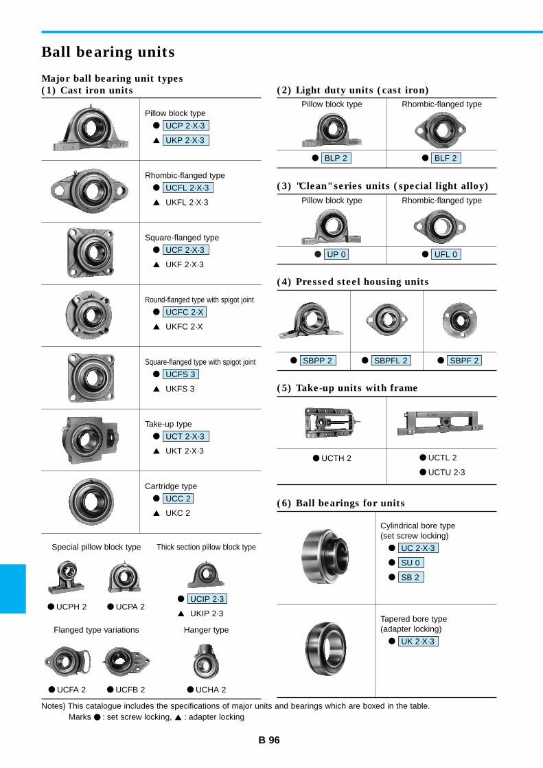
Pillow block type
UP 0
Rhombic-flanged type
UFL 0
B 96
Ball bearing units
Major ball bearing unit types
(1) Cast iron units
Pillow block type
UKP 2·X·3
UCP 2·X·3
UKIP 2·3
UCIP 2·3
(2) Light duty units (cast iron)
Pillow block type
BLP 2
Rhombic-flanged type
BLF 2
(3) "Clean" series units (special light alloy)
UCTH 2 UCTL 2
UCTU 2·3
(5) Take-up units with frame
(6) Ball bearings for units
(4) Pressed steel housing units
SBPP 2 SBPFL 2 SBPF 2
Cylindrical bore type(set screw locking)
SB 2
SU 0
UC 2·X·3
Tapered bore type(adapter locking)
UK 2·X·3
Special pillow block type
UCPH 2 UCPA 2
Thick section pillow block type
Flanged type variations
UCFA 2 UCFB 2 UCHA 2
Hanger type
Rhombic-flanged type
UKFL 2·X·3
UCFL 2·X·3
Square-flanged type
UKF 2·X·3
UCF 2·X·3
Round-flanged type with spigot joint
UKFC 2·X
UCFC 2·X
Square-flanged type with spigot joint
UKFS 3
UCFS 3
Take-up type
UKT 2·X·3
UCT 2·X·3
Cartridge type
UKC 2
UCC 2
Notes) This catalogue includes the specifications of major units and bearings which are boxed in the table.Marks : set screw locking, : adapter locking
B 97
Tolerances
Bearing radial internalclearance
Recommended fits ofinner ring and shaft(indicated by the tolerance class)
Rotation speed limits
Allowable aligning angle
• Ball bearings .............. as specified in JIS B 1558 (Tables 1 and 2).• Housings .................... as specified in JIS B 1559.
the internal spherical diametertolerance is given in Table 3.
As specified in JIS B 1520 (Table 2-1 on p. A 11).Koyo provides cylindrical bore bearings with normal radial internal clearance.Tapered bore bearings are provided with a C3 radial internal clearance in considera-tion of possible inner ring expansion caused by tightening of an adapter.
• Cylindrical bore bearings .................... h6, h7, h8, j6 (k6, k7 and m6 when heavy orimpact load is to be supported.)
• Tapered bore bearings ........................ h8, h9• High-speed blower bearings (S5) ........ h5, j5
See Table 4.
• 0.052 rad (3˚)
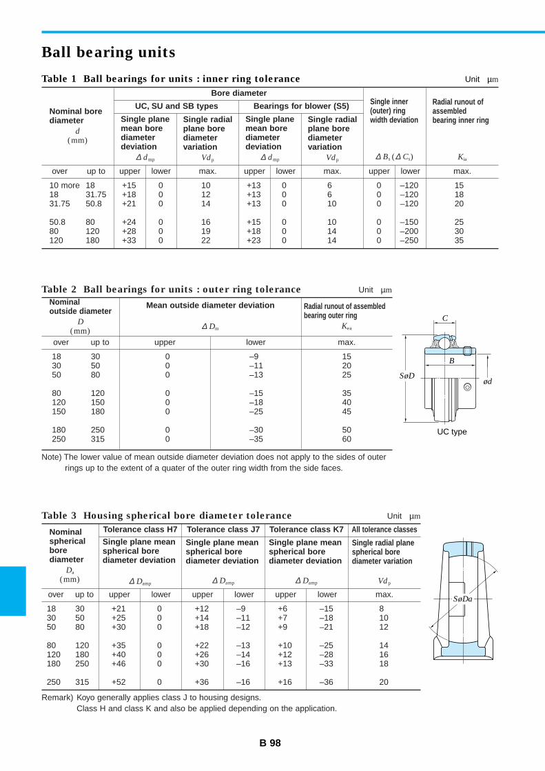
B 98
Ball bearing units
Table 1 Ball bearings for units : inner ring tolerance Unit µm
Nominal borediameter
d
(mm)
Bore diameterSingle inner(outer) ringwidth deviation
∆ Bs (∆ Cs)
Radial runout ofassembledbearing inner ring
Kia
UC, SU and SB types
Single planemean borediameterdeviation
∆ dmp
over up to upper lower
Single radialplane borediametervariation
Vdp
max.
Bearings for blower (S5)
Single planemean borediameterdeviation
∆ dmp
upper lower max. upper lower max.
Single radialplane borediametervariation
Vdp
10 more 18 +15 0 10 +13 0 6 0 –120 1518 31.75 +18 0 12 +13 0 6 0 –120 1831.75 50.8 +21 0 14 +13 0 10 0 –120 20
50.8 80 +24 0 16 +15 0 10 0 –150 2580 120 +28 0 19 +18 0 14 0 –200 30120 180 +33 0 22 +23 0 14 0 –250 35
Table 3 Housing spherical bore diameter tolerance Unit µm
Nominalsphericalborediameter
Da
(mm)
Tolerance class H7
Single plane meanspherical borediameter deviation
∆ Damp
over up to upper lower
Tolerance class J7
Single plane meanspherical borediameter deviation
∆ Damp
upper lower
Tolerance class K7 All tolerance classes
Single plane meanspherical borediameter deviation
∆ Damp
Single radial planespherical borediameter variation
Vdp
upper max.lower
18 30 +21 0 +12 –9 +6 –15 830 50 +25 0 +14 –11 +7 –18 1050 80 +30 0 +18 –12 +9 –21 12
80 120 +35 0 +22 –13 +10 –25 14120 180 +40 0 +26 –14 +12 –28 16180 250 +46 0 +30 –16 +13 –33 18
250 315 +52 0 +36 –16 +16 –36 20
Table 2 Ball bearings for units : outer ring tolerance Unit µm
Nominal outside diameter
D
(mm)
Mean outside diameter deviation
∆ Dm
Radial runout of assembledbearing outer ring
Kea
over up to upper lower max.
18 30 0 –9 1530 50 0 –11 2050 80 0 –13 25
80 120 0 –15 35120 150 0 –18 40150 180 0 –25 45
180 250 0 –30 50250 315 0 –35 60
Note) The lower value of mean outside diameter deviation does not apply to the sides of outerrings up to the extent of a quater of the outer ring width from the side faces.
Remark) Koyo generally applies class J to housing designs.Class H and class K and also be applied depending on the application.
C
B
SøDød
UC type
SøDa
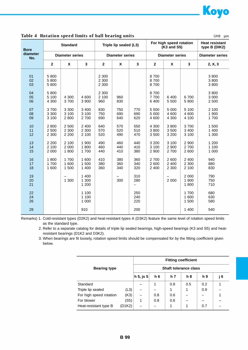
B 99
Table 4 Rotation speed limits of ball bearing units Unit µm
Borediameter
No.
Standard
Diameter series
2 X 3
Triple lip sealed (L3)
Diameter series
2 X 3
For high speed rotation(K3 and S5)
Diameter series
2
Heat resistanttype B (DIK2)
Diameter series
2, X, 3X 3
01 5 800 2 300 8 700 3 80002 5 800 2 300 8 700 3 80003 5 800 2 300 8 700 3 800
04 5 800 2 300 8 700 3 80005 5 100 4 300 4 600 2 100 960 7 700 6 400 6 700 3 00006 4 300 3 700 3 900 960 830 6 400 5 500 5 800 2 500
07 3 700 3 300 3 400 830 750 770 5 500 5 000 5 100 2 10008 3 300 3 100 3 100 750 690 690 5 000 4 600 4 600 1 90009 3 100 2 800 2 700 690 640 620 4 600 4 300 4 100 1 700
10 2 800 2 500 2 400 640 570 550 4 300 3 800 3 700 1 50011 2 500 2 300 2 300 570 520 510 3 800 3 500 3 400 1 40012 2 300 2 200 2 100 520 490 470 3 500 3 200 3 100 1 300
13 2 200 2 100 1 900 490 460 440 3 200 3 100 2 900 1 20014 2 100 2 000 1 800 460 440 410 3 100 2 900 2 700 1 10015 2 000 1 800 1 700 440 410 380 2 900 2 700 2 600 1 000
16 1 800 1 700 1 600 410 380 360 2 700 2 600 2 400 94017 1 700 1 600 1 500 380 360 340 2 600 2 400 2 300 88018 1 600 1 500 1 400 360 340 320 2 400 2 300 2 100 830
19 – 1 400 – 310 – 2 000 79020 1 300 1 300 300 280 2 000 1 900 75021 1 200 – 1 800 710
22 1 100 250 1 700 68024 1 100 240 1 600 63026 1 000 220 1 500 580
28 910 200 1 400 540
Remarks) 1. Cold-resistant types (D2K2) and heat-resistant types A (D3K2) feature the same level of rotation speed limitsas the standard type.
2. Refer to a separate catalog for details of triple lip sealed bearings, high-speed bearings (K3 and S5) and heat-resistant bearings (D1K2 and D3K2).
3. When bearings are fit loosely, rotation speed limits should be compensated for by the fitting coefficient givenbelow.
Bearing type
Fitting coefficient
Shaft tolerance class
h 5, js 5 h 6 h 7 h 8 h 9 j 6
StandardTriple lip sealed (L3)For high speed rotation (K3)For blower (S5)Heat-resistant type B (D1K2)
– 1 0.8 0.5 0.2 1– – 1 1 0.9 –– 0.8 0.6 – – 11 0.8 0.6 – – –– – 1 1 0.7 –
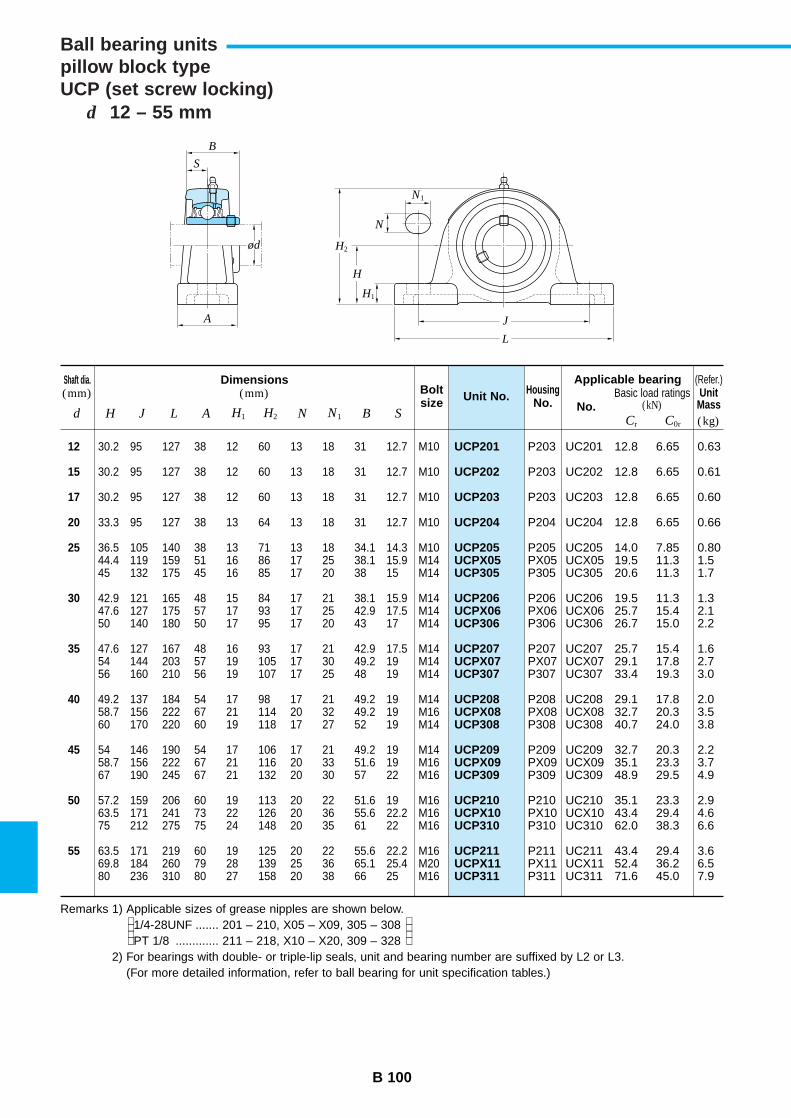
B 100
d 12 – 55 mm
Ball bearing unitspillow block typeUCP (set screw locking)
UCP201
UCP202
UCP203
UCP204
UCP205UCPX05UCP305
UCP206UCPX06UCP306
UCP207UCPX07UCP307
UCP208UCPX08UCP308
UCP209UCPX09UCP309
UCP210UCPX10UCP310
UCP211UCPX11UCP311
Unit No.Shaft dia.(mm)
Dimensions(mm) Bolt
sizeHousing
No. No.d H J L A H1 H2 N N1 B S
Applicable bearingBasic load ratings
(kN)
12
15
17
20
25
30
35
40
45
50
55
30.2 95 127 38 12 60 13 18 31 12.7 M10
30.2 95 127 38 12 60 13 18 31 12.7 M10
30.2 95 127 38 12 60 13 18 31 12.7 M10
33.3 95 127 38 13 64 13 18 31 12.7 M10
36.5 105 140 38 13 71 13 18 34.1 14.3 M1044.4 119 159 51 16 86 17 25 38.1 15.9 M1445 132 175 45 16 85 17 20 38 15 M14
42.9 121 165 48 15 84 17 21 38.1 15.9 M1447.6 127 175 57 17 93 17 25 42.9 17.5 M1450 140 180 50 17 95 17 20 43 17 M14
47.6 127 167 48 16 93 17 21 42.9 17.5 M1454 144 203 57 19 105 17 30 49.2 19 M1456 160 210 56 19 107 17 25 48 19 M14
49.2 137 184 54 17 98 17 21 49.2 19 M1458.7 156 222 67 21 114 20 32 49.2 19 M1660 170 220 60 19 118 17 27 52 19 M14
54 146 190 54 17 106 17 21 49.2 19 M1458.7 156 222 67 21 116 20 33 51.6 19 M1667 190 245 67 21 132 20 30 57 22 M16
57.2 159 206 60 19 113 20 22 51.6 19 M1663.5 171 241 73 22 126 20 36 55.6 22.2 M1675 212 275 75 24 148 20 35 61 22 M16
63.5 171 219 60 19 125 20 22 55.6 22.2 M1669.8 184 260 79 28 139 25 36 65.1 25.4 M2080 236 310 80 27 158 20 38 66 25 M16
P203 UC201 12.8 6.65 0.63
P203 UC202 12.8 6.65 0.61
P203 UC203 12.8 6.65 0.60
P204 UC204 12.8 6.65 0.66
P205 UC205 14.0 7.85 0.80PX05 UCX05 19.5 11.3 1.5P305 UC305 20.6 11.3 1.7
P206 UC206 19.5 11.3 1.3PX06 UCX06 25.7 15.4 2.1P306 UC306 26.7 15.0 2.2
P207 UC207 25.7 15.4 1.6PX07 UCX07 29.1 17.8 2.7P307 UC307 33.4 19.3 3.0
P208 UC208 29.1 17.8 2.0PX08 UCX08 32.7 20.3 3.5P308 UC308 40.7 24.0 3.8
P209 UC209 32.7 20.3 2.2PX09 UCX09 35.1 23.3 3.7P309 UC309 48.9 29.5 4.9
P210 UC210 35.1 23.3 2.9PX10 UCX10 43.4 29.4 4.6P310 UC310 62.0 38.3 6.6
P211 UC211 43.4 29.4 3.6PX11 UCX11 52.4 36.2 6.5P311 UC311 71.6 45.0 7.9
(Refer.)
(kg)Cr C0r
UnitMass
Remarks 1) Applicable sizes of grease nipples are shown below.1/4-28UNF ....... 201 – 210, X05 – X09, 305 – 308PT 1/8 ............. 211 – 218, X10 – X20, 309 – 328
2) For bearings with double- or triple-lip seals, unit and bearing number are suffixed by L2 or L3.(For more detailed information, refer to ball bearing for unit specification tables.)
B
S
ød
A
L
J
H
H2
N1
N
H1
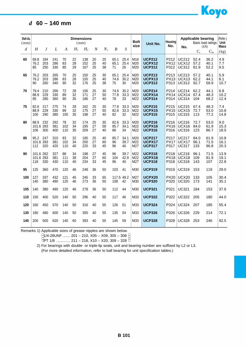
B 101
d 60 – 140 mm
UCP212UCPX12UCP312
UCP213UCPX13UCP313
UCP214UCPX14UCP314
UCP215UCPX15UCP315
UCP216UCPX16UCP316
UCP217UCPX17UCP317
UCP218UCPX18UCP318
UCP319
UCPX20UCP320
UCP321
UCP322
UCP324
UCP326
UCP328
Unit No.Shaft dia.(mm)
Dimensions(mm) Bolt
sizeHousing
No. No.d H J L A H1 H2 N N1 B S
Applicable bearingBasic load ratings
(kN)
60
65
70
75
80
85
90
95
100
105
110
120
130
140
69.8 184 241 70 22 138 20 25 65.1 25.4 M1676.2 203 286 83 28 152 25 40 65.1 25.4 M2085 250 330 85 29 167 25 38 71 26 M20
76.2 203 265 70 25 150 25 30 65.1 25.4 M2076.2 203 286 83 28 155 25 40 74.6 30.2 M2090 260 340 90 32 176 25 38 75 30 M20
79.4 210 266 72 28 156 25 30 74.6 30.2 M2088.9 229 330 89 32 171 27 50 77.8 33.3 M2295 280 360 90 35 186 27 40 78 33 M22
82.6 217 275 74 28 162 25 30 77.8 33.3 M2088.9 229 330 89 32 175 27 50 82.6 33.3 M22100 290 380 100 35 198 27 40 82 32 M22
88.9 232 292 78 32 174 25 35 82.6 33.3 M20101.6 283 381 102 34 195 27 58 85.7 34.1 M22106 300 400 110 35 209 27 40 86 34 M22
95.2 247 310 83 32 185 25 40 85.7 34.1 M20101.6 283 381 102 34 200 27 60 96 39.7 M22112 320 420 110 40 220 33 45 96 40 M27
101.6 262 327 88 34 198 27 45 96 39.7 M22101.6 283 381 111 38 204 27 60 104 42.9 M22118 330 430 110 40 234 33 45 96 40 M27
125 360 470 120 46 248 36 50 103 41 M30
127 337 432 121 45 245 33 65 117.5 49.2 M27140 380 490 120 46 273 36 50 108 42 M30
140 380 490 120 46 278 36 50 112 44 M30
150 400 520 140 50 296 40 55 117 46 M33
160 450 570 140 50 316 40 55 126 51 M33
180 480 600 140 50 355 40 55 135 54 M33
200 500 620 140 60 393 40 55 145 59 M33
P212 UC212 52.4 36.2 4.9PX12 UCX12 57.2 40.1 7.7P312 UC312 81.9 52.2 9.5
P213 UC213 57.2 40.1 5.9PX13 UCX13 62.2 44.1 8.1P313 UC313 92.7 59.9 10.7
P214 UC214 62.2 44.1 6.8PX14 UCX14 67.4 48.3 10.2P314 UC314 104 68.2 12.4
P215 UC215 67.4 48.3 7.4PX15 UCX15 72.7 53.0 10.8P315 UC315 113 77.2 14.8
P216 UC216 72.7 53.0 9.0PX16 UCX16 84.0 61.9 15.3P316 UC316 123 86.7 18.5
P217 UC217 84.0 61.9 10.8PX17 UCX17 96.1 71.5 16.1P317 UC317 133 96.8 20.3
P218 UC218 96.1 71.5 13.9PX18 UCX18 109 81.9 19.1P318 UC318 143 107 22.8
P319 UC319 153 119 29.0
PX20 UCX20 133 105 30.4P320 UC320 173 141 35.1
P321 UC321 184 153 37.6
P322 UC322 205 180 44.0
P324 UC324 207 185 55.4
P326 UC326 229 214 72.1
P328 UC328 253 246 92.5
(Refer.)
(kg)Cr C0r
UnitMass
Remarks 1) Applicable sizes of grease nipples are shown below.1/4-28UNF ....... 201 – 210, X05 – X09, 305 – 308PT 1/8 ............. 211 – 218, X10 – X20, 309 – 328
2) For bearings with double- or triple-lip seals, unit and bearing number are suffixed by L2 or L3.(For more detailed information, refer to ball bearing for unit specification tables.)
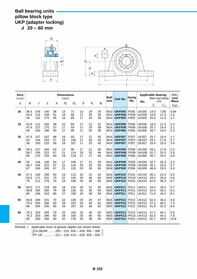
B 102
d 20 – 60 mm
Ball bearing unitspillow block typeUKP (adapter locking)
UKP205UKPX05UKP305
UKP206UKPX06UKP306
UKP207UKPX07UKP307
UKP208UKPX08UKP308
UKP209UKPX09UKP309
UKP210UKPX10UKP310
UKP211UKPX11UKP311
UKP212UKPX12UKP312
UKP213UKPX13UKP313
Unit No.Shaft dia.(mm)
Dimensions(mm) Bolt
sizeHousing
No. No.d H J L A H1 H2 N N1 B1
Applicable bearingBasic load ratings
(kN)
20
25
30
35
40
45
50
55
60
36.5 105 140 38 13 71 13 18 29 M1044.4 119 159 51 16 86 17 25 35 M1445 132 175 45 16 85 17 20 35 M14
42.9 121 165 48 15 84 17 21 31 M1447.6 127 175 57 17 93 17 25 38 M1450 140 180 50 17 95 17 20 38 M14
47.6 127 167 48 16 93 17 21 35 M1454 144 203 57 19 105 17 30 43 M1456 160 210 56 19 107 17 25 43 M14
49.2 137 184 54 17 98 17 21 36 M1458.7 156 222 67 21 114 20 32 46 M1660 170 220 60 19 118 17 27 46 M14
54 146 190 54 17 106 17 21 39 M1458.7 156 222 67 21 116 20 33 50 M1667 190 245 67 21 132 20 30 50 M16
57.2 159 206 60 19 113 20 22 42 M1663.5 171 241 73 22 126 20 36 55 M1675 212 275 75 24 148 20 35 55 M16
63.5 171 219 60 19 125 20 22 45 M1669.8 184 260 79 28 139 25 36 59 M2080 236 310 80 27 158 20 38 59 M16
69.8 184 241 70 22 138 20 25 47 M1676.2 203 286 83 28 152 25 40 62 M2085 250 330 85 29 167 25 38 62 M20
76.2 203 265 70 25 150 25 30 50 M2076.2 203 286 83 28 155 25 40 65 M2090 260 340 90 32 176 25 38 65 M20
P205 UK205 14.0 7.85 0.84PX05 UKX05 19.5 11.3 1.5P305 UK305 20.6 11.3 1.7
P206 UK206 19.5 11.3 1.4PX06 UKX06 25.7 15.4 2.1P306 UK306 26.7 15.0 2.3
P207 UK207 25.7 15.4 1.7PX07 UKX07 29.1 17.8 2.7P307 UK307 33.4 19.3 3.0
P208 UK208 29.1 17.8 2.0PX08 UKX08 32.7 20.3 3.5P308 UK308 40.7 24.0 3.8
P209 UK209 32.7 20.3 2.3PX09 UKX09 35.1 23.3 3.7P309 UK309 48.9 29.5 5.0
P210 UK210 35.1 23.3 3.0PX10 UKX10 43.4 29.4 4.6P310 UK310 62.0 38.3 6.7
P211 UK211 43.4 29.4 3.7PX11 UKX11 52.4 36.2 6.2P311 UK311 71.6 45.0 8.1
P212 UK212 52.4 36.2 4.8PX12 UKX12 57.2 40.1 7.5P312 UK312 81.9 52.2 9.4
P213 UK213 57.2 40.1 5.8PX13 UKX13 62.2 44.1 7.8P313 UK313 92.7 59.9 10.8
(Refer.)
(kg)Cr C0r
UnitMass
Remark ) Applicable sizes of grease nipples are shown below.1/4-28UNF ....... 205 – 210, X05 – X09, 305 – 308PT 1/8 ............. 211 – 218, X10 – X20, 309 – 328
B1
A
ød
L
J
H
H2
N1
N
H1
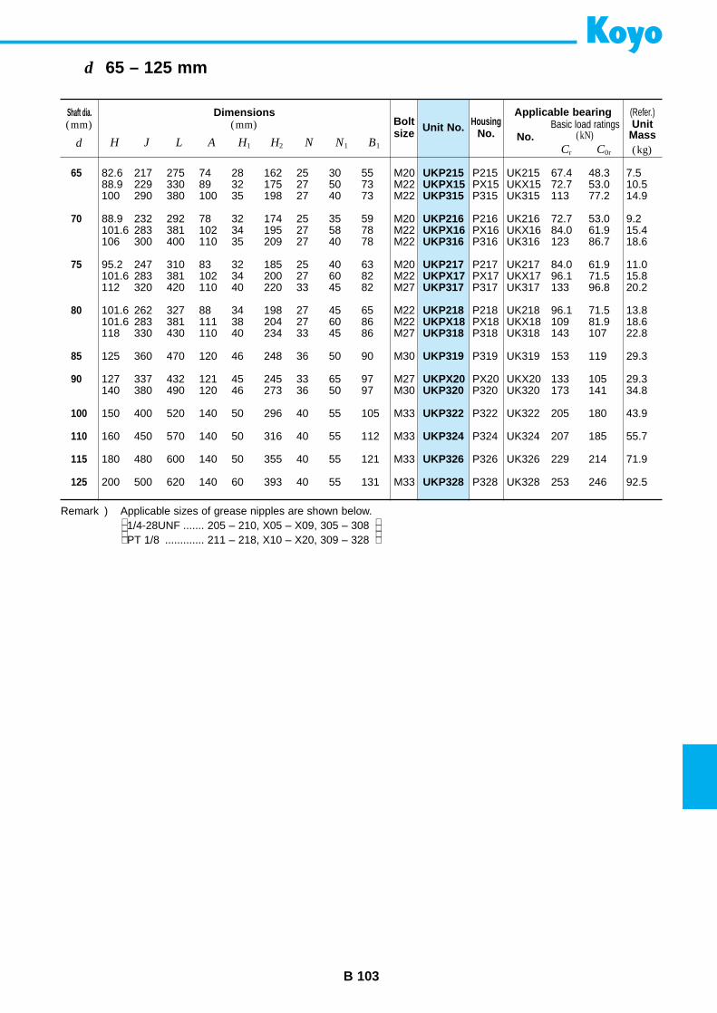
B 103
d 65 – 125 mm
UKP215UKPX15UKP315
UKP216UKPX16UKP316
UKP217UKPX17UKP317
UKP218UKPX18UKP318
UKP319
UKPX20UKP320
UKP322
UKP324
UKP326
UKP328
Unit No.Shaft dia.(mm)
Dimensions(mm) Bolt
sizeHousing
No. No.d H J L A H1 H2 N N1 B1
Applicable bearingBasic load ratings
(kN)
65
70
75
80
85
90
100
110
115
125
82.6 217 275 74 28 162 25 30 55 M2088.9 229 330 89 32 175 27 50 73 M22100 290 380 100 35 198 27 40 73 M22
88.9 232 292 78 32 174 25 35 59 M20101.6 283 381 102 34 195 27 58 78 M22106 300 400 110 35 209 27 40 78 M22
95.2 247 310 83 32 185 25 40 63 M20101.6 283 381 102 34 200 27 60 82 M22112 320 420 110 40 220 33 45 82 M27
101.6 262 327 88 34 198 27 45 65 M22101.6 283 381 111 38 204 27 60 86 M22118 330 430 110 40 234 33 45 86 M27
125 360 470 120 46 248 36 50 90 M30
127 337 432 121 45 245 33 65 97 M27140 380 490 120 46 273 36 50 97 M30
150 400 520 140 50 296 40 55 105 M33
160 450 570 140 50 316 40 55 112 M33
180 480 600 140 50 355 40 55 121 M33
200 500 620 140 60 393 40 55 131 M33
P215 UK215 67.4 48.3 7.5PX15 UKX15 72.7 53.0 10.5P315 UK315 113 77.2 14.9
P216 UK216 72.7 53.0 9.2PX16 UKX16 84.0 61.9 15.4P316 UK316 123 86.7 18.6
P217 UK217 84.0 61.9 11.0PX17 UKX17 96.1 71.5 15.8P317 UK317 133 96.8 20.2
P218 UK218 96.1 71.5 13.8PX18 UKX18 109 81.9 18.6P318 UK318 143 107 22.8
P319 UK319 153 119 29.3
PX20 UKX20 133 105 29.3P320 UK320 173 141 34.8
P322 UK322 205 180 43.9
P324 UK324 207 185 55.7
P326 UK326 229 214 71.9
P328 UK328 253 246 92.5
(Refer.)
(kg)Cr C0r
UnitMass
Remark ) Applicable sizes of grease nipples are shown below.1/4-28UNF ....... 205 – 210, X05 – X09, 305 – 308PT 1/8 ............. 211 – 218, X10 – X20, 309 – 328
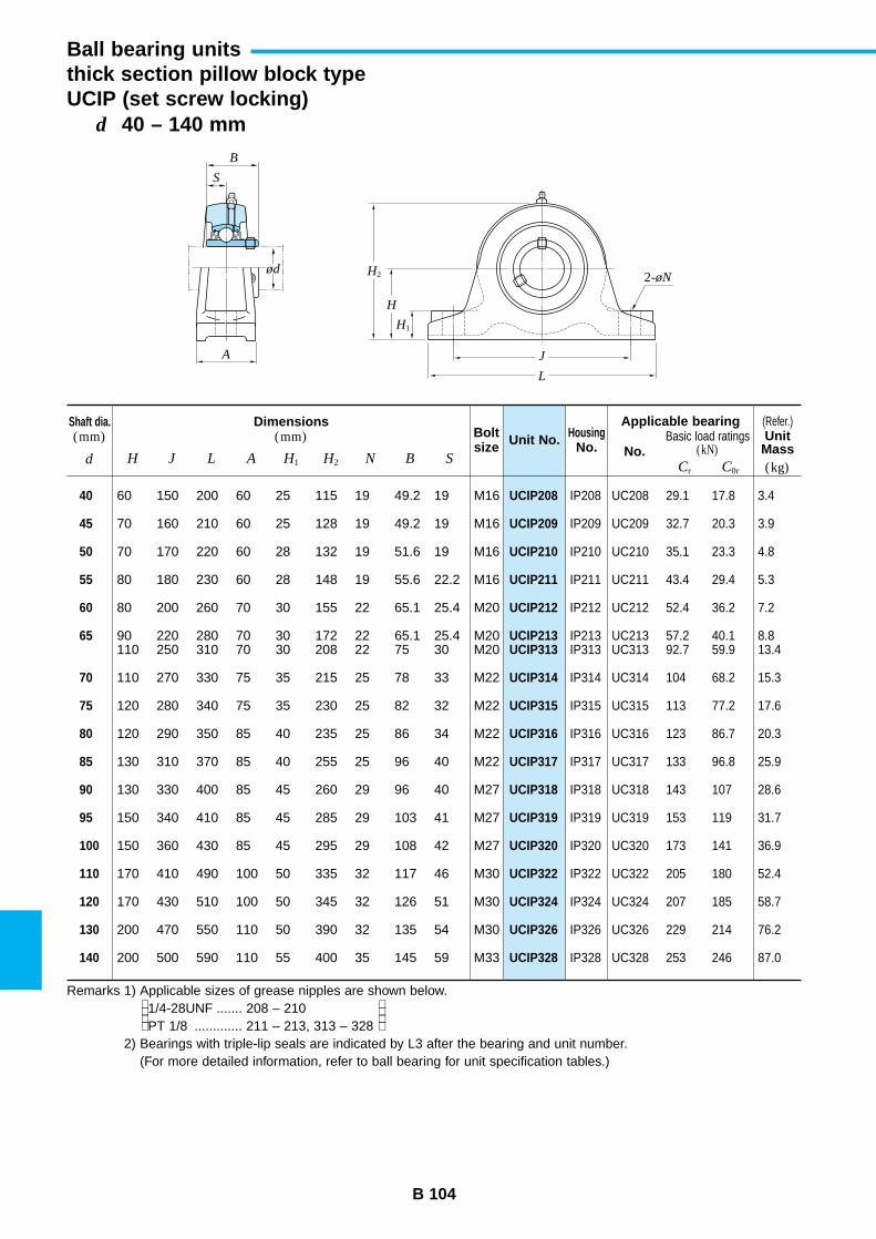
B 104
d 40 – 140 mm
Ball bearing unitsthick section pillow block typeUCIP (set screw locking)
UCIP208
UCIP209
UCIP210
UCIP211
UCIP212
UCIP213UCIP313
UCIP314
UCIP315
UCIP316
UCIP317
UCIP318
UCIP319
UCIP320
UCIP322
UCIP324
UCIP326
UCIP328
Unit No.Shaft dia.(mm)
Dimensions(mm) Bolt
sizeHousing
No. No.d H J L A H1 H2 N B S
Applicable bearingBasic load ratings
(kN)
40
45
50
55
60
65
70
75
80
85
90
95
100
110
120
130
140
60 150 200 60 25 115 19 49.2 19 M16
70 160 210 60 25 128 19 49.2 19 M16
70 170 220 60 28 132 19 51.6 19 M16
80 180 230 60 28 148 19 55.6 22.2 M16
80 200 260 70 30 155 22 65.1 25.4 M20
90 220 280 70 30 172 22 65.1 25.4 M20110 250 310 70 30 208 22 75 30 M20
110 270 330 75 35 215 25 78 33 M22
120 280 340 75 35 230 25 82 32 M22
120 290 350 85 40 235 25 86 34 M22
130 310 370 85 40 255 25 96 40 M22
130 330 400 85 45 260 29 96 40 M27
150 340 410 85 45 285 29 103 41 M27
150 360 430 85 45 295 29 108 42 M27
170 410 490 100 50 335 32 117 46 M30
170 430 510 100 50 345 32 126 51 M30
200 470 550 110 50 390 32 135 54 M30
200 500 590 110 55 400 35 145 59 M33
IP208 UC208 29.1 17.8 3.4
IP209 UC209 32.7 20.3 3.9
IP210 UC210 35.1 23.3 4.8
IP211 UC211 43.4 29.4 5.3
IP212 UC212 52.4 36.2 7.2
IP213 UC213 57.2 40.1 8.8IP313 UC313 92.7 59.9 13.4
IP314 UC314 104 68.2 15.3
IP315 UC315 113 77.2 17.6
IP316 UC316 123 86.7 20.3
IP317 UC317 133 96.8 25.9
IP318 UC318 143 107 28.6
IP319 UC319 153 119 31.7
IP320 UC320 173 141 36.9
IP322 UC322 205 180 52.4
IP324 UC324 207 185 58.7
IP326 UC326 229 214 76.2
IP328 UC328 253 246 87.0
(Refer.)
(kg)Cr C0r
UnitMass
Remarks 1) Applicable sizes of grease nipples are shown below.1/4-28UNF ....... 208 – 210PT 1/8 ............. 211 – 213, 313 – 328
2) Bearings with triple-lip seals are indicated by L3 after the bearing and unit number.(For more detailed information, refer to ball bearing for unit specification tables.)
B
S
ød
A
L
J
H
H2
H1
2-øN

B 105
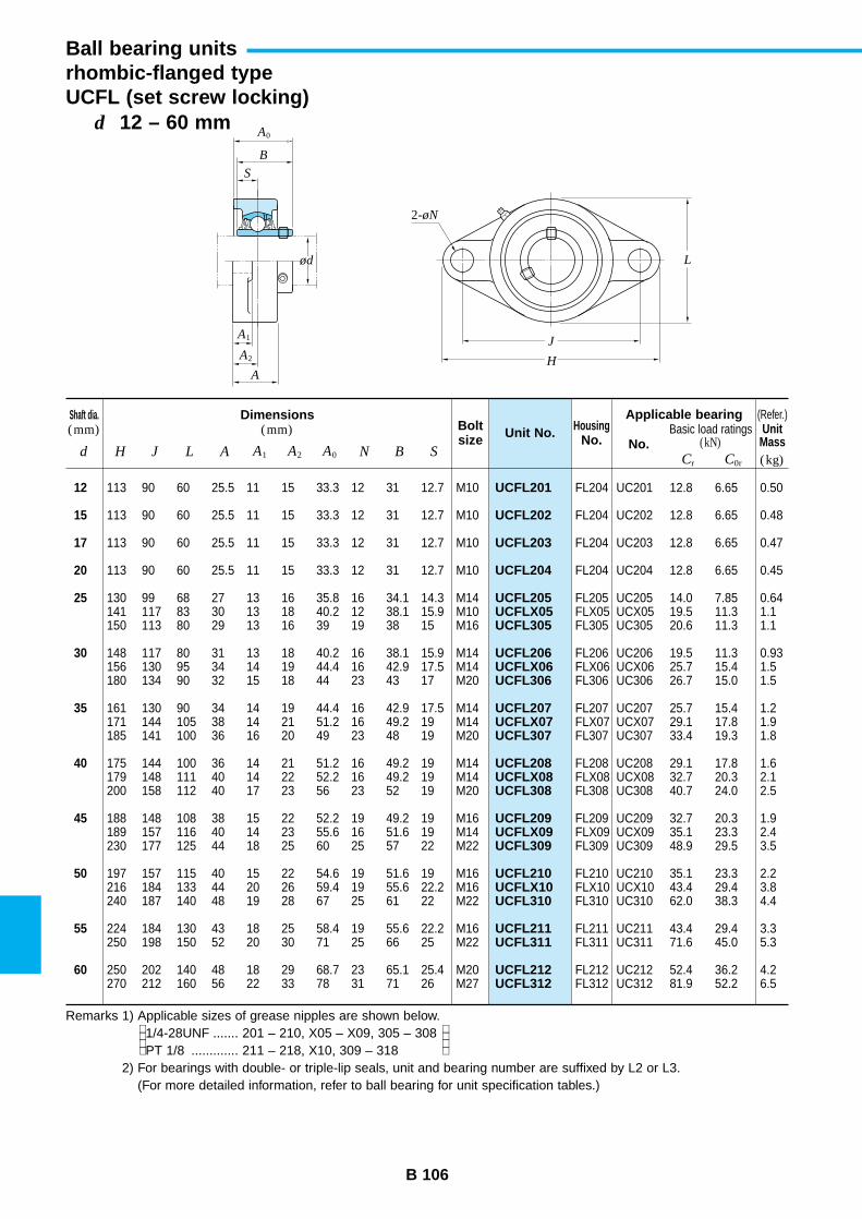
B 106
d 12 – 60 mm
Ball bearing unitsrhombic-flanged typeUCFL (set screw locking)
UCFL201
UCFL202
UCFL203
UCFL204
UCFL205UCFLX05UCFL305
UCFL206UCFLX06UCFL306
UCFL207UCFLX07UCFL307
UCFL208UCFLX08UCFL308
UCFL209UCFLX09UCFL309
UCFL210UCFLX10UCFL310
UCFL211UCFL311
UCFL212UCFL312
Unit No.Shaft dia.(mm)
Dimensions(mm) Bolt
sizeHousing
No. No.d H J L A A1 A2 A0 N B S
Applicable bearingBasic load ratings
(kN)
12
15
17
20
25
30
35
40
45
50
55
60
113 90 60 25.5 11 15 33.3 12 31 12.7 M10
113 90 60 25.5 11 15 33.3 12 31 12.7 M10
113 90 60 25.5 11 15 33.3 12 31 12.7 M10
113 90 60 25.5 11 15 33.3 12 31 12.7 M10
130 99 68 27 13 16 35.8 16 34.1 14.3 M14141 117 83 30 13 18 40.2 12 38.1 15.9 M10150 113 80 29 13 16 39 19 38 15 M16
148 117 80 31 13 18 40.2 16 38.1 15.9 M14156 130 95 34 14 19 44.4 16 42.9 17.5 M14180 134 90 32 15 18 44 23 43 17 M20
161 130 90 34 14 19 44.4 16 42.9 17.5 M14171 144 105 38 14 21 51.2 16 49.2 19 M14185 141 100 36 16 20 49 23 48 19 M20
175 144 100 36 14 21 51.2 16 49.2 19 M14179 148 111 40 14 22 52.2 16 49.2 19 M14200 158 112 40 17 23 56 23 52 19 M20
188 148 108 38 15 22 52.2 19 49.2 19 M16189 157 116 40 14 23 55.6 16 51.6 19 M14230 177 125 44 18 25 60 25 57 22 M22
197 157 115 40 15 22 54.6 19 51.6 19 M16216 184 133 44 20 26 59.4 19 55.6 22.2 M16240 187 140 48 19 28 67 25 61 22 M22
224 184 130 43 18 25 58.4 19 55.6 22.2 M16250 198 150 52 20 30 71 25 66 25 M22
250 202 140 48 18 29 68.7 23 65.1 25.4 M20270 212 160 56 22 33 78 31 71 26 M27
FL204 UC201 12.8 6.65 0.50
FL204 UC202 12.8 6.65 0.48
FL204 UC203 12.8 6.65 0.47
FL204 UC204 12.8 6.65 0.45
FL205 UC205 14.0 7.85 0.64FLX05 UCX05 19.5 11.3 1.1FL305 UC305 20.6 11.3 1.1
FL206 UC206 19.5 11.3 0.93FLX06 UCX06 25.7 15.4 1.5FL306 UC306 26.7 15.0 1.5
FL207 UC207 25.7 15.4 1.2FLX07 UCX07 29.1 17.8 1.9FL307 UC307 33.4 19.3 1.8
FL208 UC208 29.1 17.8 1.6FLX08 UCX08 32.7 20.3 2.1FL308 UC308 40.7 24.0 2.5
FL209 UC209 32.7 20.3 1.9FLX09 UCX09 35.1 23.3 2.4FL309 UC309 48.9 29.5 3.5
FL210 UC210 35.1 23.3 2.2FLX10 UCX10 43.4 29.4 3.8FL310 UC310 62.0 38.3 4.4
FL211 UC211 43.4 29.4 3.3FL311 UC311 71.6 45.0 5.3
FL212 UC212 52.4 36.2 4.2FL312 UC312 81.9 52.2 6.5
(Refer.)
(kg)Cr C0r
UnitMass
Remarks 1) Applicable sizes of grease nipples are shown below.1/4-28UNF ....... 201 – 210, X05 – X09, 305 – 308PT 1/8 ............. 211 – 218, X10, 309 – 318
2) For bearings with double- or triple-lip seals, unit and bearing number are suffixed by L2 or L3.(For more detailed information, refer to ball bearing for unit specification tables.)
H
J
L
2-øN
B
S
ød
A2
A1
A
A0
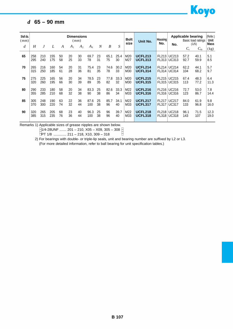
B 107
d 65 – 90 mm
UCFL213UCFL313
UCFL214UCFL314
UCFL215UCFL315
UCFL216UCFL316
UCFL217UCFL317
UCFL218UCFL318
Unit No.Shaft dia.(mm)
Dimensions(mm) Bolt
sizeHousing
No. No.d H J L A A1 A2 A0 N B S
Applicable bearingBasic load ratings
(kN)
65
70
75
80
85
90
258 210 155 50 20 30 69.7 23 65.1 25.4 M20295 240 175 58 25 33 78 31 75 30 M27
265 216 160 54 20 31 75.4 23 74.6 30.2 M20315 250 185 61 28 36 81 35 78 33 M30
275 225 165 56 20 34 78.5 23 77.8 33.3 M20320 260 195 66 30 39 89 35 82 32 M30
290 233 180 58 20 34 83.3 25 82.6 33.3 M22355 285 210 68 32 38 90 38 86 34 M33
305 248 190 63 22 36 87.6 25 85.7 34.1 M22370 300 220 74 32 44 100 38 96 40 M33
320 265 205 68 23 40 96.3 25 96 39.7 M22385 315 235 76 36 44 100 38 96 40 M33
FL213 UC213 57.2 40.1 5.1FL313 UC313 92.7 59.9 8.5
FL214 UC214 62.2 44.1 5.7FL314 UC314 104 68.2 9.7
FL215 UC215 67.4 48.3 6.4FL315 UC315 113 77.2 11.3
FL216 UC216 72.7 53.0 7.8FL316 UC316 123 86.7 14.4
FL217 UC217 84.0 61.9 9.8FL317 UC317 133 96.8 16.0
FL218 UC218 96.1 71.5 12.3FL318 UC318 143 107 19.0
(Refer.)
(kg)Cr C0r
UnitMass
Remarks 1) Applicable sizes of grease nipples are shown below.1/4-28UNF ....... 201 – 210, X05 – X09, 305 – 308PT 1/8 ............. 211 – 218, X10, 309 – 318
2) For bearings with double- or triple-lip seals, unit and bearing number are suffixed by L2 or L3.(For more detailed information, refer to ball bearing for unit specification tables.)
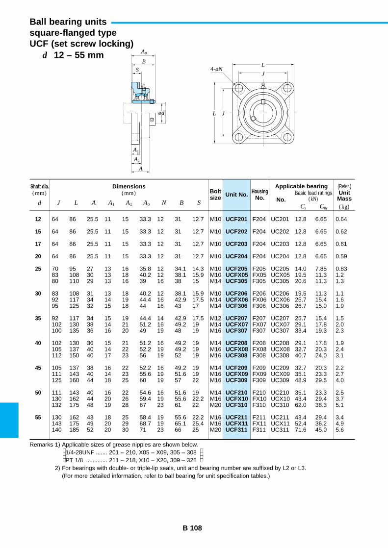
B 108
d 12 – 55 mm
Ball bearing unitssquare-flanged typeUCF (set screw locking)
UCF201
UCF202
UCF203
UCF204
UCF205UCFX05UCF305
UCF206UCFX06UCF306
UCF207UCFX07UCF307
UCF208UCFX08UCF308
UCF209UCFX09UCF309
UCF210UCFX10UCF310
UCF211UCFX11UCF311
Unit No.Shaft dia.(mm)
Dimensions(mm) Bolt
sizeHousing
No. No.d J L A A1 A2 A0 N B S
Applicable bearingBasic load ratings
(kN)
12
15
17
20
25
30
35
40
45
50
55
64 86 25.5 11 15 33.3 12 31 12.7 M10
64 86 25.5 11 15 33.3 12 31 12.7 M10
64 86 25.5 11 15 33.3 12 31 12.7 M10
64 86 25.5 11 15 33.3 12 31 12.7 M10
70 95 27 13 16 35.8 12 34.1 14.3 M1083 108 30 13 18 40.2 12 38.1 15.9 M1080 110 29 13 16 39 16 38 15 M14
83 108 31 13 18 40.2 12 38.1 15.9 M1092 117 34 14 19 44.4 16 42.9 17.5 M1495 125 32 15 18 44 16 43 17 M14
92 117 34 15 19 44.4 14 42.9 17.5 M12102 130 38 14 21 51.2 16 49.2 19 M14100 135 36 16 20 49 19 48 19 M16
102 130 36 15 21 51.2 16 49.2 19 M14105 137 40 14 22 52.2 19 49.2 19 M16112 150 40 17 23 56 19 52 19 M16
105 137 38 16 22 52.2 16 49.2 19 M14111 143 40 14 23 55.6 19 51.6 19 M16125 160 44 18 25 60 19 57 22 M16
111 143 40 16 22 54.6 16 51.6 19 M14130 162 44 20 26 59.4 19 55.6 22.2 M16132 175 48 19 28 67 23 61 22 M20
130 162 43 18 25 58.4 19 55.6 22.2 M16143 175 49 20 29 68.7 19 65.1 25.4 M16140 185 52 20 30 71 23 66 25 M20
F204 UC201 12.8 6.65 0.64
F204 UC202 12.8 6.65 0.62
F204 UC203 12.8 6.65 0.61
F204 UC204 12.8 6.65 0.59
F205 UC205 14.0 7.85 0.83FX05 UCX05 19.5 11.3 1.2F305 UC305 20.6 11.3 1.3
F206 UC206 19.5 11.3 1.1FX06 UCX06 25.7 15.4 1.6F306 UC306 26.7 15.0 1.9
F207 UC207 25.7 15.4 1.5FX07 UCX07 29.1 17.8 2.0F307 UC307 33.4 19.3 2.3
F208 UC208 29.1 17.8 1.9FX08 UCX08 32.7 20.3 2.4F308 UC308 40.7 24.0 3.1
F209 UC209 32.7 20.3 2.2FX09 UCX09 35.1 23.3 2.7F309 UC309 48.9 29.5 4.0
F210 UC210 35.1 23.3 2.5FX10 UCX10 43.4 29.4 3.7F310 UC310 62.0 38.3 5.1
F211 UC211 43.4 29.4 3.4FX11 UCX11 52.4 36.2 4.9F311 UC311 71.6 45.0 5.6
(Refer.)
(kg)Cr C0r
UnitMass
Remarks 1) Applicable sizes of grease nipples are shown below.1/4-28UNF ....... 201 – 210, X05 – X09, 305 – 308PT 1/8 ............. 211 – 218, X10 – X20, 309 – 328
2) For bearings with double- or triple-lip seals, unit and bearing number are suffixed by L2 or L3.(For more detailed information, refer to ball bearing for unit specification tables.)
L J
L
J4-øN
B
S
ød
A2
A1
A
A0
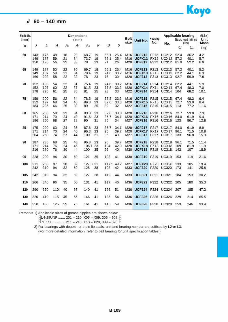
B 109
d 60 – 140 mm
UCF212UCFX12UCF312
UCF213UCFX13UCF313
UCF214UCFX14UCF314
UCF215UCFX15UCF315
UCF216UCFX16UCF316
UCF217UCFX17UCF317
UCF218UCFX18UCF318
UCF319
UCFX20UCF320
UCF321
UCF322
UCF324
UCF326
UCF328
Unit No.Shaft dia.(mm)
Dimensions(mm) Bolt
sizeHousing
No. No.d J L A A1 A2 A0 N B S
Applicable bearingBasic load ratings
(kN)
60
65
70
75
80
85
90
95
100
105
110
120
130
140
143 175 48 18 29 68.7 19 65.1 25.4 M16149 187 59 21 34 73.7 19 65.1 25.4 M16150 195 56 22 33 78 23 71 26 M20
149 187 50 22 30 69.7 19 65.1 25.4 M16149 187 59 21 34 78.4 19 74.6 30.2 M16166 208 58 22 33 78 23 75 30 M20
152 193 54 22 31 75.4 19 74.6 30.2 M16152 197 60 22 37 81.5 23 77.8 33.3 M20178 226 61 25 36 81 25 78 33 M22
159 200 56 22 34 78.5 19 77.8 33.3 M16152 197 68 24 40 89.3 23 82.6 33.3 M20184 236 66 25 39 89 25 82 32 M22
165 208 58 22 34 83.3 23 82.6 33.3 M20171 214 70 24 40 91.6 23 85.7 34.1 M20196 250 68 27 38 90 31 86 34 M27
175 220 63 24 36 87.6 23 85.7 34.1 M20171 214 70 24 40 96.3 23 96 39.7 M20204 260 74 27 44 100 31 96 40 M27
187 235 68 25 40 96.3 23 96 39.7 M20171 214 76 24 45 106.1 23 104 42.9 M20216 280 76 30 44 100 35 96 40 M30
228 290 94 30 59 121 35 103 41 M30
211 268 97 28 59 127.3 31 117.5 49.2 M27242 310 94 32 59 125 38 108 42 M33
242 310 94 32 59 127 38 112 44 M33
266 340 96 35 60 131 41 117 46 M36
290 370 110 40 65 140 41 126 51 M36
320 410 115 45 65 146 41 135 54 M36
350 450 125 55 75 161 41 145 59 M36
F212 UC212 52.4 36.2 4.2FX12 UCX12 57.2 40.1 5.7F312 UC312 81.9 52.2 6.9
F213 UC213 57.2 40.1 5.2FX13 UCX13 62.2 44.1 6.3F313 UC313 92.7 59.9 7.8
F214 UC214 62.2 44.1 5.9FX14 UCX14 67.4 48.3 7.0F314 UC314 104 68.2 10.1
F215 UC215 67.4 48.3 6.4FX15 UCX15 72.7 53.0 8.4F315 UC315 113 77.2 11.6
F216 UC216 72.7 53.0 7.3FX16 UCX16 84.0 61.9 9.4F316 UC316 123 86.7 12.8
F217 UC217 84.0 61.9 8.9FX17 UCX17 96.1 71.5 10.8F317 UC317 133 96.8 15.3
F218 UC218 96.1 71.5 11.4FX18 UCX18 109 81.9 11.9F318 UC318 143 107 18.9
F319 UC319 153 119 21.6
FX20 UCX20 133 105 19.4F320 UC320 173 141 25.8
F321 UC321 184 153 30.2
F322 UC322 205 180 35.3
F324 UC324 207 185 47.3
F326 UC326 229 214 65.5
F328 UC328 253 246 93.4
(Refer.)
(kg)Cr C0r
UnitMass
Remarks 1) Applicable sizes of grease nipples are shown below.1/4-28UNF ....... 201 – 210, X05 – X09, 305 – 308PT 1/8 ............. 211 – 218, X10 – X20, 309 – 328
2) For bearings with double- or triple-lip seals, unit and bearing number are suffixed by L2 or L3.(For more detailed information, refer to ball bearing for unit specification tables.)
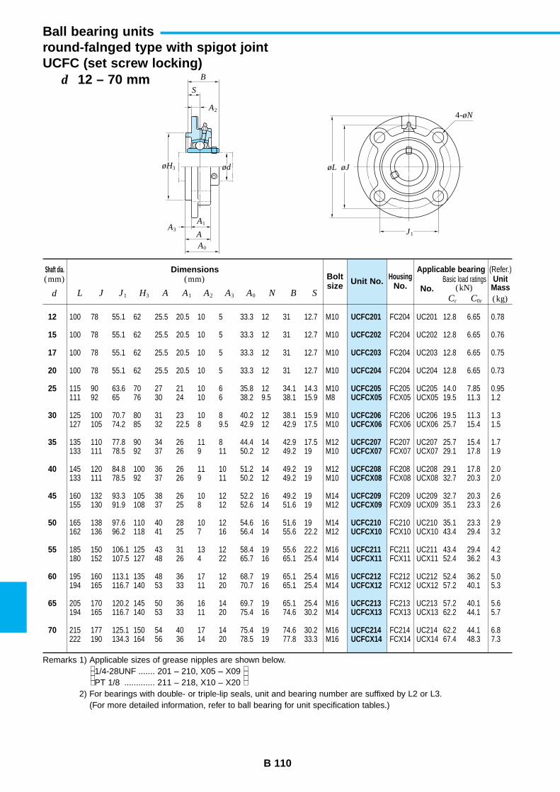
B 110
d 12 – 70 mm
Ball bearing unitsround-falnged type with spigot jointUCFC (set screw locking)
UCFC201
UCFC202
UCFC203
UCFC204
UCFC205UCFCX05
UCFC206UCFCX06
UCFC207UCFCX07
UCFC208UCFCX08
UCFC209UCFCX09
UCFC210UCFCX10
UCFC211UCFCX11
UCFC212UCFCX12
UCFC213UCFCX13
UCFC214UCFCX14
Unit No.Shaft dia.(mm)
Dimensions(mm) Bolt
sizeHousing
No. No.d L J J1 H3 A A1 A2 A3 A0 N B S
Applicable bearingBasic load ratings
(kN)
12
15
17
20
25
30
35
40
45
50
55
60
65
70
100 78 55.1 62 25.5 20.5 10 5 33.3 12 31 12.7 M10
100 78 55.1 62 25.5 20.5 10 5 33.3 12 31 12.7 M10
100 78 55.1 62 25.5 20.5 10 5 33.3 12 31 12.7 M10
100 78 55.1 62 25.5 20.5 10 5 33.3 12 31 12.7 M10
115 90 63.6 70 27 21 10 6 35.8 12 34.1 14.3 M10111 92 65 76 30 24 10 6 38.2 9.5 38.1 15.9 M8
125 100 70.7 80 31 23 10 8 40.2 12 38.1 15.9 M10127 105 74.2 85 32 22.5 8 9.5 42.9 12 42.9 17.5 M10
135 110 77.8 90 34 26 11 8 44.4 14 42.9 17.5 M12133 111 78.5 92 37 26 9 11 50.2 12 49.2 19 M10
145 120 84.8 100 36 26 11 10 51.2 14 49.2 19 M12133 111 78.5 92 37 26 9 11 50.2 12 49.2 19 M10
160 132 93.3 105 38 26 10 12 52.2 16 49.2 19 M14155 130 91.9 108 37 25 8 12 52.6 14 51.6 19 M12
165 138 97.6 110 40 28 10 12 54.6 16 51.6 19 M14162 136 96.2 118 41 25 7 16 56.4 14 55.6 22.2 M12
185 150 106.1 125 43 31 13 12 58.4 19 55.6 22.2 M16180 152 107.5 127 48 26 4 22 65.7 16 65.1 25.4 M14
195 160 113.1 135 48 36 17 12 68.7 19 65.1 25.4 M16194 165 116.7 140 53 33 11 20 70.7 16 65.1 25.4 M14
205 170 120.2 145 50 36 16 14 69.7 19 65.1 25.4 M16194 165 116.7 140 53 33 11 20 75.4 16 74.6 30.2 M14
215 177 125.1 150 54 40 17 14 75.4 19 74.6 30.2 M16222 190 134.3 164 56 36 14 20 78.5 19 77.8 33.3 M16
FC204 UC201 12.8 6.65 0.78
FC204 UC202 12.8 6.65 0.76
FC204 UC203 12.8 6.65 0.75
FC204 UC204 12.8 6.65 0.73
FC205 UC205 14.0 7.85 0.95FCX05 UCX05 19.5 11.3 1.2
FC206 UC206 19.5 11.3 1.3FCX06 UCX06 25.7 15.4 1.5
FC207 UC207 25.7 15.4 1.7FCX07 UCX07 29.1 17.8 1.9
FC208 UC208 29.1 17.8 2.0FCX08 UCX08 32.7 20.3 2.0
FC209 UC209 32.7 20.3 2.6FCX09 UCX09 35.1 23.3 2.6
FC210 UC210 35.1 23.3 2.9FCX10 UCX10 43.4 29.4 3.2
FC211 UC211 43.4 29.4 4.2FCX11 UCX11 52.4 36.2 4.3
FC212 UC212 52.4 36.2 5.0FCX12 UCX12 57.2 40.1 5.3
FC213 UC213 57.2 40.1 5.6FCX13 UCX13 62.2 44.1 5.7
FC214 UC214 62.2 44.1 6.8FCX14 UCX14 67.4 48.3 7.3
(Refer.)
(kg)Cr C0r
UnitMass
Remarks 1) Applicable sizes of grease nipples are shown below.1/4-28UNF ....... 201 – 210, X05 – X09PT 1/8 ............. 211 – 218, X10 – X20
2) For bearings with double- or triple-lip seals, unit and bearing number are suffixed by L2 or L3.(For more detailed information, refer to ball bearing for unit specification tables.)
B
S
ødøH3
A
A0
A1A3
A2
øL øJ
J1
4-øN
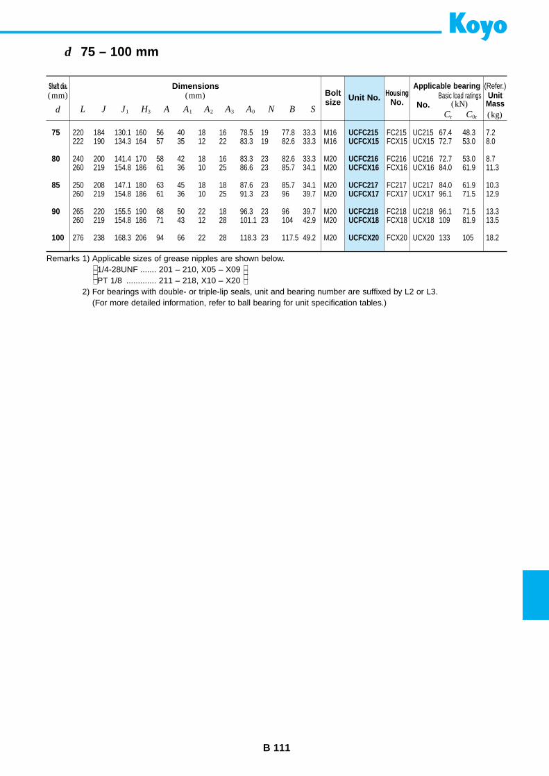
B 111
d 75 – 100 mm
UCFC215UCFCX15
UCFC216UCFCX16
UCFC217UCFCX17
UCFC218UCFCX18
UCFCX20
Unit No.Shaft dia.(mm)
Dimensions(mm) Bolt
sizeHousing
No. No.d L J J1 H3 A A1 A2 A3 A0 N B S
Applicable bearingBasic load ratings
(kN)
75
80
85
90
100
220 184 130.1 160 56 40 18 16 78.5 19 77.8 33.3 M16222 190 134.3 164 57 35 12 22 83.3 19 82.6 33.3 M16
240 200 141.4 170 58 42 18 16 83.3 23 82.6 33.3 M20260 219 154.8 186 61 36 10 25 86.6 23 85.7 34.1 M20
250 208 147.1 180 63 45 18 18 87.6 23 85.7 34.1 M20260 219 154.8 186 61 36 10 25 91.3 23 96 39.7 M20
265 220 155.5 190 68 50 22 18 96.3 23 96 39.7 M20260 219 154.8 186 71 43 12 28 101.1 23 104 42.9 M20
276 238 168.3 206 94 66 22 28 118.3 23 117.5 49.2 M20
FC215 UC215 67.4 48.3 7.2FCX15 UCX15 72.7 53.0 8.0
FC216 UC216 72.7 53.0 8.7FCX16 UCX16 84.0 61.9 11.3
FC217 UC217 84.0 61.9 10.3FCX17 UCX17 96.1 71.5 12.9
FC218 UC218 96.1 71.5 13.3FCX18 UCX18 109 81.9 13.5
FCX20 UCX20 133 105 18.2
(Refer.)
(kg)Cr C0r
UnitMass
Remarks 1) Applicable sizes of grease nipples are shown below.1/4-28UNF ....... 201 – 210, X05 – X09PT 1/8 ............. 211 – 218, X10 – X20
2) For bearings with double- or triple-lip seals, unit and bearing number are suffixed by L2 or L3.(For more detailed information, refer to ball bearing for unit specification tables.)
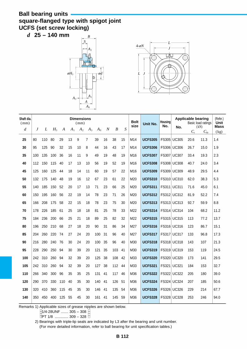
B 112
d 25 – 140 mm
Ball bearing unitssquare-flanged type with spigot jointUCFS (set screw locking)
UCFS305
UCFS306
UCFS307
UCFS308
UCFS309
UCFS310
UCFS311
UCFS312
UCFS313
UCFS314
UCFS315
UCFS316
UCFS317
UCFS318
UCFS319
UCFS320
UCFS321
UCFS322
UCFS324
UCFS326
UCFS328
Unit No.Shaft dia.(mm)
Dimensions(mm) Bolt
sizeHousing
No. No.d J L H3 A A1 A2 A3 A0 N B S
Applicable bearingBasic load ratings
(kN)
25
30
35
40
45
50
55
60
65
70
75
80
85
90
95
100
105
110
120
130
140
80 110 80 29 13 9 7 39 16 38 15 M14
95 125 90 32 15 10 8 44 16 43 17 M14
100 135 100 36 16 11 9 49 19 48 19 M16
112 150 115 40 17 13 10 56 19 52 19 M16
125 160 125 44 18 14 11 60 19 57 22 M16
132 175 140 48 19 16 12 67 23 61 22 M20
140 185 150 52 20 17 13 71 23 66 25 M20
150 195 160 56 22 19 14 78 23 71 26 M20
166 208 175 58 22 15 18 78 23 75 30 M20
178 226 185 61 25 18 18 81 25 78 33 M22
184 236 200 66 25 21 18 89 25 82 32 M22
196 250 210 68 27 18 20 90 31 86 34 M27
204 260 220 74 27 24 20 100 31 96 40 M27
216 280 240 76 30 24 20 100 35 96 40 M30
228 290 250 94 30 39 20 121 35 103 41 M30
242 310 260 94 32 39 20 125 38 108 42 M33
242 310 260 94 32 39 20 127 38 112 44 M33
266 340 300 96 35 35 25 131 41 117 46 M36
290 370 330 110 40 35 30 140 41 126 51 M36
320 410 360 115 45 35 30 146 41 135 54 M36
350 450 400 125 55 45 30 161 41 145 59 M36
FS305 UC305 20.6 11.3 1.4
FS306 UC306 26.7 15.0 1.9
FS307 UC307 33.4 19.3 2.3
FS308 UC308 40.7 24.0 3.4
FS309 UC309 48.9 29.5 4.4
FS310 UC310 62.0 38.3 5.3
FS311 UC311 71.6 45.0 6.1
FS312 UC312 81.9 52.2 7.4
FS313 UC313 92.7 59.9 8.8
FS314 UC314 104 68.2 11.2
FS315 UC315 113 77.2 13.7
FS316 UC316 123 86.7 15.1
FS317 UC317 133 96.8 17.3
FS318 UC318 143 107 21.3
FS319 UC319 153 119 24.5
FS320 UC320 173 141 29.5
FS321 UC321 184 153 32.7
FS322 UC322 205 180 39.0
FS324 UC324 207 185 50.6
FS326 UC326 229 214 67.7
FS328 UC328 253 246 94.0
(Refer.)
(kg)Cr C0r
UnitMass
Remarks 1) Applicable sizes of grease nipples are shown below.1/4-28UNF ....... 305 – 308PT 1/8 ............. 309 – 328
2) Bearings with triple-lip seals are indicated by L3 after the bearing and unit number.(For more detailed information, refer to ball bearing for unit specification tables.)
B
S
ødøH3
A1
A2
A3A
A0
L
L
J
J
4-øN

B 113
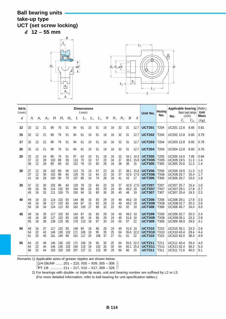
B 114
d 12 – 55 mm
Ball bearing unitstake-up typeUCT (set screw locking)
UCT201
UCT202
UCT203
UCT204
UCT205UCTX05UCT305
UCT206UCTX06UCT306
UCT207UCTX07UCT307
UCT208UCTX08UCT308
UCT209UCTX09UCT309
UCT210UCTX10UCT310
UCT211UCTX11UCT311
Unit No.Shaft dia.(mm)
Dimensions(mm) Housing
No. No.d A A1 A2 H H1 H2 L L1 L2 L3 N N1 N2 B S
Applicable bearingBasic load ratings
(kN)
12
15
17
20
25
30
35
40
45
50
55
32 12 21 89 76 51 94 61 10 51 19 16 32 31 12.7
32 12 21 89 76 51 94 61 10 51 19 16 32 31 12.7
32 12 21 89 76 51 94 61 10 51 19 16 32 31 12.7
32 12 21 89 76 51 94 61 10 51 19 16 32 31 12.7
32 12 24 89 76 51 97 62 10 51 19 16 32 34.1 14.337 12 28 102 89 56 113 70 10 57 22 16 37 38.1 15.936 12 26 89 80 62 122 76 12 65 26 16 36 38 15
37 12 28 102 89 56 113 70 10 57 22 16 37 38.1 15.937 12 30 102 89 64 129 78 13 64 22 16 37 42.9 17.541 16 28 100 90 70 137 85 14 74 28 18 41 43 17
37 12 30 102 89 64 129 78 13 64 22 16 37 42.9 17.549 16 36 114 102 83 144 88 15 83 29 19 49 49.2 1945 16 32 111 100 75 150 94 15 80 30 20 45 48 19
49 16 33 114 102 83 144 88 16 83 29 19 49 49.2 1949 16 36 117 102 83 144 87 15 83 29 19 49 49.2 1950 18 34 124 112 83 162 100 17 89 32 22 50 52 19
49 16 35 117 102 83 144 87 16 83 29 19 49 49.2 1949 16 38 117 102 83 149 90 16 86 29 19 49 51.6 1955 18 38 138 125 90 178 110 18 97 34 24 55 57 22
49 16 37 117 102 83 149 90 16 86 29 19 49 51.6 1964 22 42 146 130 102 171 106 19 95 35 25 64 55.6 22.261 20 40 151 140 98 191 117 20 106 37 27 61 61 22
64 22 38 146 130 102 171 106 19 95 35 25 64 55.6 22.264 22 44 146 130 102 194 119 19 102 35 32 64 65.1 25.466 22 44 163 150 105 207 127 21 115 39 29 66 66 25
T204 UC201 12.8 6.65 0.81
T204 UC202 12.8 6.65 0.79
T204 UC203 12.8 6.65 0.78
T204 UC204 12.8 6.65 0.76
T205 UC205 14.0 7.85 0.84TX05 UCX05 19.5 11.3 1.4T305 UC305 20.6 11.3 1.4
T206 UC206 19.5 11.3 1.3TX06 UCX06 25.7 15.4 1.7T306 UC306 26.7 15.0 1.8
T207 UC207 25.7 15.4 1.6TX07 UCX07 29.1 17.8 2.7T307 UC307 33.4 19.3 2.3
T208 UC208 29.1 17.8 2.5TX08 UCX08 32.7 20.3 2.6T308 UC308 40.7 24.0 3.0
T209 UC209 32.7 20.3 2.4TX09 UCX09 35.1 23.3 2.9T309 UC309 48.9 29.5 4.1
T210 UC210 35.1 23.3 2.6TX10 UCX10 43.4 29.4 4.4T310 UC310 62.0 38.3 4.9
T211 UC211 43.4 29.4 4.0TX11 UCX11 52.4 36.2 5.3T311 UC311 71.6 45.0 6.1
(Refer.)
(kg)Cr C0r
UnitMass
Remarks 1) Applicable sizes of grease nipples are shown below.1/4-28UNF ....... 201 – 210, X05 – X09, 305 – 308PT 1/8 ............. 211 – 217, X10 – X17, 309 – 328
2) For bearings with double- or triple-lip seals, unit and bearing number are suffixed by L2 or L3.(For more detailed information, refer to ball bearing for unit specification tables.)
B
S
ød
A1
H1 H2 HN2
N1
øN
A2
AL
L3
L2
L1
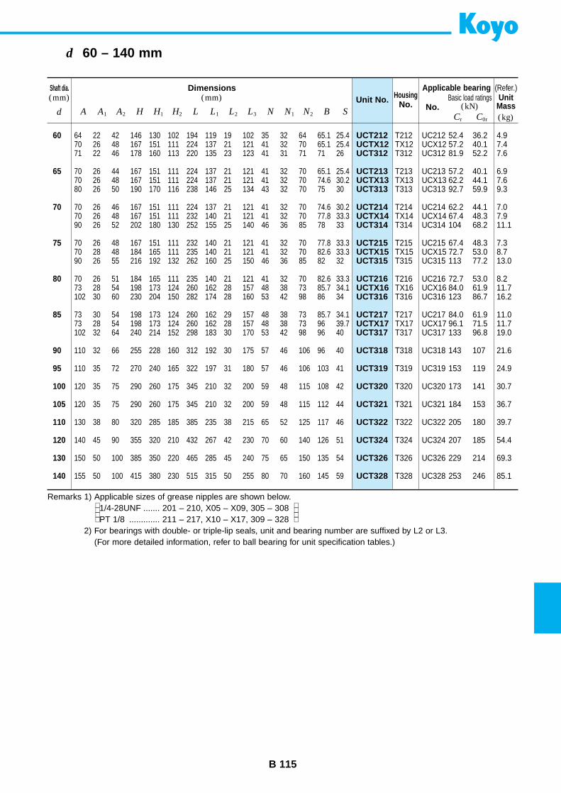
B 115
d 60 – 140 mm
UCT212UCTX12UCT312
UCT213UCTX13UCT313
UCT214UCTX14UCT314
UCT215UCTX15UCT315
UCT216UCTX16UCT316
UCT217UCTX17UCT317
UCT318
UCT319
UCT320
UCT321
UCT322
UCT324
UCT326
UCT328
Unit No.Shaft dia.(mm)
Dimensions(mm) Housing
No. No.d A A1 A2 H H1 H2 L L1 L2 L3 N N1 N2 B S
Applicable bearingBasic load ratings
(kN)
60
65
70
75
80
85
90
95
100
105
110
120
130
140
64 22 42 146 130 102 194 119 19 102 35 32 64 65.1 25.470 26 48 167 151 111 224 137 21 121 41 32 70 65.1 25.471 22 46 178 160 113 220 135 23 123 41 31 71 71 26
70 26 44 167 151 111 224 137 21 121 41 32 70 65.1 25.470 26 48 167 151 111 224 137 21 121 41 32 70 74.6 30.280 26 50 190 170 116 238 146 25 134 43 32 70 75 30
70 26 46 167 151 111 224 137 21 121 41 32 70 74.6 30.270 26 48 167 151 111 232 140 21 121 41 32 70 77.8 33.390 26 52 202 180 130 252 155 25 140 46 36 85 78 33
70 26 48 167 151 111 232 140 21 121 41 32 70 77.8 33.370 28 48 184 165 111 235 140 21 121 41 32 70 82.6 33.390 26 55 216 192 132 262 160 25 150 46 36 85 82 32
70 26 51 184 165 111 235 140 21 121 41 32 70 82.6 33.373 28 54 198 173 124 260 162 28 157 48 38 73 85.7 34.1102 30 60 230 204 150 282 174 28 160 53 42 98 86 34
73 30 54 198 173 124 260 162 29 157 48 38 73 85.7 34.173 28 54 198 173 124 260 162 28 157 48 38 73 96 39.7102 32 64 240 214 152 298 183 30 170 53 42 98 96 40
110 32 66 255 228 160 312 192 30 175 57 46 106 96 40
110 35 72 270 240 165 322 197 31 180 57 46 106 103 41
120 35 75 290 260 175 345 210 32 200 59 48 115 108 42
120 35 75 290 260 175 345 210 32 200 59 48 115 112 44
130 38 80 320 285 185 385 235 38 215 65 52 125 117 46
140 45 90 355 320 210 432 267 42 230 70 60 140 126 51
150 50 100 385 350 220 465 285 45 240 75 65 150 135 54
155 50 100 415 380 230 515 315 50 255 80 70 160 145 59
T212 UC212 52.4 36.2 4.9TX12 UCX12 57.2 40.1 7.4T312 UC312 81.9 52.2 7.6
T213 UC213 57.2 40.1 6.9TX13 UCX13 62.2 44.1 7.6T313 UC313 92.7 59.9 9.3
T214 UC214 62.2 44.1 7.0TX14 UCX14 67.4 48.3 7.9T314 UC314 104 68.2 11.1
T215 UC215 67.4 48.3 7.3TX15 UCX15 72.7 53.0 8.7T315 UC315 113 77.2 13.0
T216 UC216 72.7 53.0 8.2TX16 UCX16 84.0 61.9 11.7T316 UC316 123 86.7 16.2
T217 UC217 84.0 61.9 11.0TX17 UCX17 96.1 71.5 11.7T317 UC317 133 96.8 19.0
T318 UC318 143 107 21.6
T319 UC319 153 119 24.9
T320 UC320 173 141 30.7
T321 UC321 184 153 36.7
T322 UC322 205 180 39.7
T324 UC324 207 185 54.4
T326 UC326 229 214 69.3
T328 UC328 253 246 85.1
(Refer.)
(kg)Cr C0r
UnitMass
Remarks 1) Applicable sizes of grease nipples are shown below.1/4-28UNF ....... 201 – 210, X05 – X09, 305 – 308PT 1/8 ............. 211 – 217, X10 – X17, 309 – 328
2) For bearings with double- or triple-lip seals, unit and bearing number are suffixed by L2 or L3.(For more detailed information, refer to ball bearing for unit specification tables.)
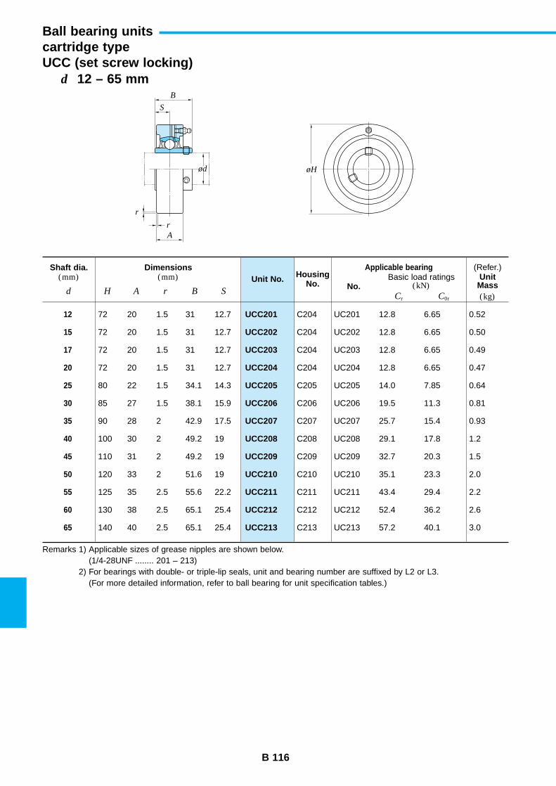
B 116
d 12 – 65 mm
Ball bearing unitscartridge typeUCC (set screw locking)
UCC201
UCC202
UCC203
UCC204
UCC205
UCC206
UCC207
UCC208
UCC209
UCC210
UCC211
UCC212
UCC213
Unit No.Shaft dia.
(mm)Dimensions
(mm) HousingNo. No.
d H A r B S
Applicable bearingBasic load ratings
(kN)
12
15
17
20
25
30
35
40
45
50
55
60
65
72 20 1.5 31 12.7
72 20 1.5 31 12.7
72 20 1.5 31 12.7
72 20 1.5 31 12.7
80 22 1.5 34.1 14.3
85 27 1.5 38.1 15.9
90 28 2 42.9 17.5
100 30 2 49.2 19
110 31 2 49.2 19
120 33 2 51.6 19
125 35 2.5 55.6 22.2
130 38 2.5 65.1 25.4
140 40 2.5 65.1 25.4
C204 UC201 12.8 6.65 0.52
C204 UC202 12.8 6.65 0.50
C204 UC203 12.8 6.65 0.49
C204 UC204 12.8 6.65 0.47
C205 UC205 14.0 7.85 0.64
C206 UC206 19.5 11.3 0.81
C207 UC207 25.7 15.4 0.93
C208 UC208 29.1 17.8 1.2
C209 UC209 32.7 20.3 1.5
C210 UC210 35.1 23.3 2.0
C211 UC211 43.4 29.4 2.2
C212 UC212 52.4 36.2 2.6
C213 UC213 57.2 40.1 3.0
(Refer.)
(kg)Cr C0r
UnitMass
Remarks 1) Applicable sizes of grease nipples are shown below.(1/4-28UNF ........ 201 – 213)
2) For bearings with double- or triple-lip seals, unit and bearing number are suffixed by L2 or L3.(For more detailed information, refer to ball bearing for unit specification tables.)
B
S
r
r
ød øH
A
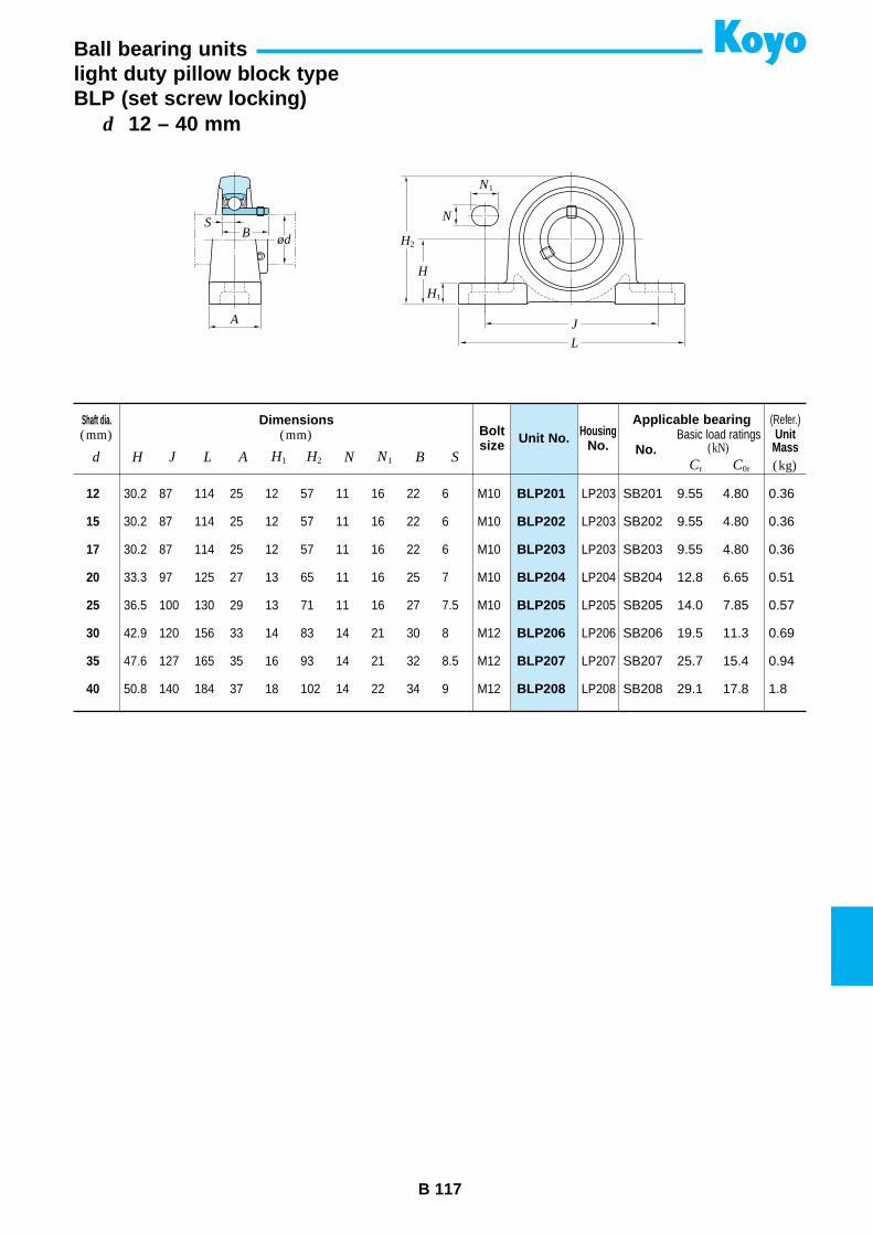
B 117
d 12 – 40 mm
Ball bearing unitslight duty pillow block typeBLP (set screw locking)
BLP201
BLP202
BLP203
BLP204
BLP205
BLP206
BLP207
BLP208
Unit No.Shaft dia.(mm)
Dimensions(mm) Bolt
sizeHousing
No. No.d H J L A H1 H2 N N1 B S
Applicable bearingBasic load ratings
(kN)
12
15
17
20
25
30
35
40
30.2 87 114 25 12 57 11 16 22 6 M10
30.2 87 114 25 12 57 11 16 22 6 M10
30.2 87 114 25 12 57 11 16 22 6 M10
33.3 97 125 27 13 65 11 16 25 7 M10
36.5 100 130 29 13 71 11 16 27 7.5 M10
42.9 120 156 33 14 83 14 21 30 8 M12
47.6 127 165 35 16 93 14 21 32 8.5 M12
50.8 140 184 37 18 102 14 22 34 9 M12
LP203 SB201 9.55 4.80 0.36
LP203 SB202 9.55 4.80 0.36
LP203 SB203 9.55 4.80 0.36
LP204 SB204 12.8 6.65 0.51
LP205 SB205 14.0 7.85 0.57
LP206 SB206 19.5 11.3 0.69
LP207 SB207 25.7 15.4 0.94
LP208 SB208 29.1 17.8 1.8
(Refer.)
(kg)Cr C0r
UnitMass
BS
ød
A
L
J
H
H2
H1
N
N1
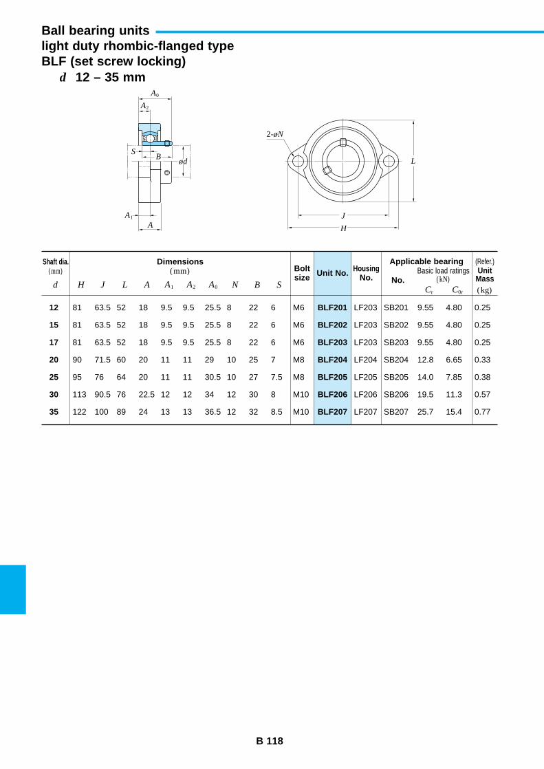
B 118
d 12 – 35 mm
Ball bearing unitslight duty rhombic-flanged typeBLF (set screw locking)
BLF201
BLF202
BLF203
BLF204
BLF205
BLF206
BLF207
Unit No.Shaft dia.
(mm)Dimensions
(mm) Boltsize
HousingNo. No.
d H J L A A1 A2 A0 N B S
Applicable bearingBasic load ratings
(kN)
12
15
17
20
25
30
35
81 63.5 52 18 9.5 9.5 25.5 8 22 6 M6
81 63.5 52 18 9.5 9.5 25.5 8 22 6 M6
81 63.5 52 18 9.5 9.5 25.5 8 22 6 M6
90 71.5 60 20 11 11 29 10 25 7 M8
95 76 64 20 11 11 30.5 10 27 7.5 M8
113 90.5 76 22.5 12 12 34 12 30 8 M10
122 100 89 24 13 13 36.5 12 32 8.5 M10
LF203 SB201 9.55 4.80 0.25
LF203 SB202 9.55 4.80 0.25
LF203 SB203 9.55 4.80 0.25
LF204 SB204 12.8 6.65 0.33
LF205 SB205 14.0 7.85 0.38
LF206 SB206 19.5 11.3 0.57
LF207 SB207 25.7 15.4 0.77
(Refer.)
(kg)Cr C0r
UnitMass
ød
A1
A
B
A0
A2
S
H
L
J
2-øN
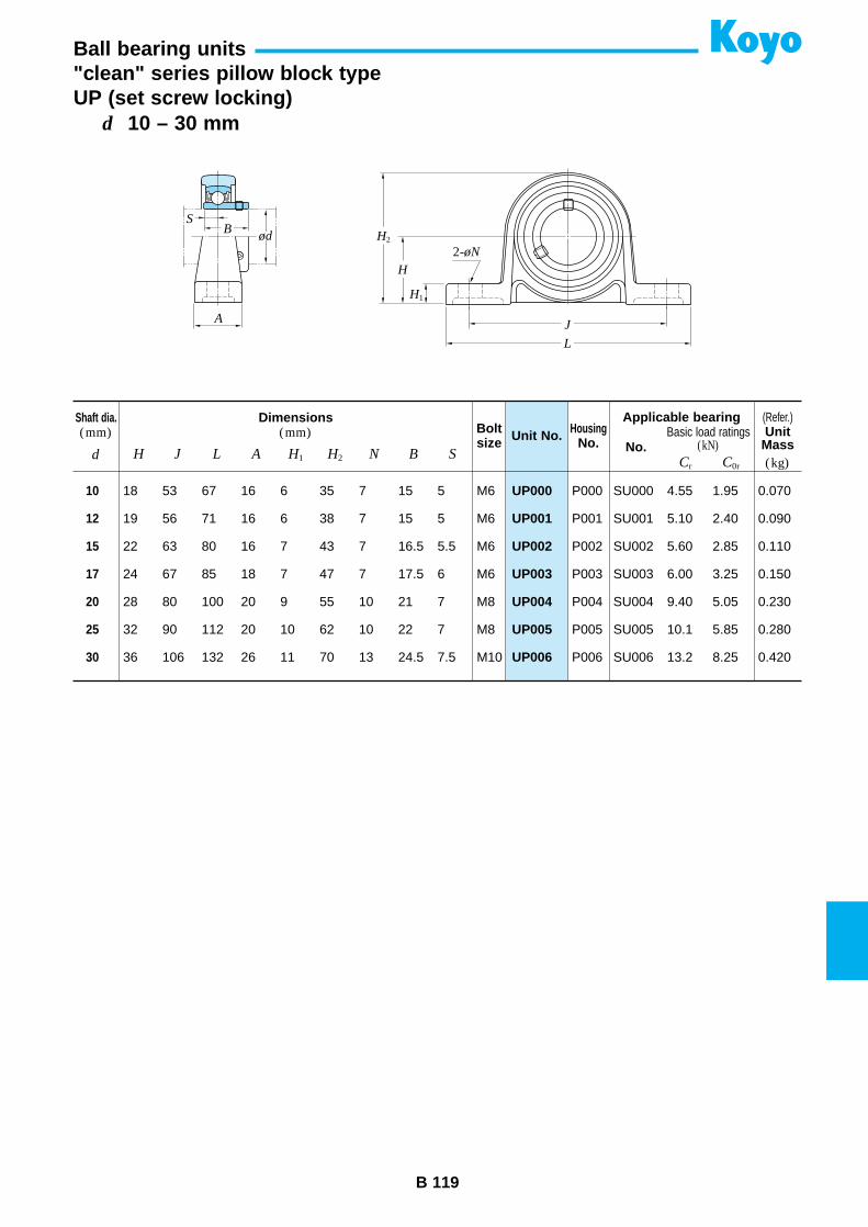
B 119
d 10 – 30 mm
Ball bearing units"clean" series pillow block typeUP (set screw locking)
UP000
UP001
UP002
UP003
UP004
UP005
UP006
Unit No.Shaft dia.(mm)
Dimensions(mm) Bolt
sizeHousing
No. No.d H J L A H1 H2 N B S
Applicable bearingBasic load ratings
(kN)
10
12
15
17
20
25
30
18 53 67 16 6 35 7 15 5 M6
19 56 71 16 6 38 7 15 5 M6
22 63 80 16 7 43 7 16.5 5.5 M6
24 67 85 18 7 47 7 17.5 6 M6
28 80 100 20 9 55 10 21 7 M8
32 90 112 20 10 62 10 22 7 M8
36 106 132 26 11 70 13 24.5 7.5 M10
P000 SU000 4.55 1.95 0.070
P001 SU001 5.10 2.40 0.090
P002 SU002 5.60 2.85 0.110
P003 SU003 6.00 3.25 0.150
P004 SU004 9.40 5.05 0.230
P005 SU005 10.1 5.85 0.280
P006 SU006 13.2 8.25 0.420
(Refer.)
(kg)Cr C0r
UnitMass
BS
ød
A
L
J
H
H2
H1
2-øN
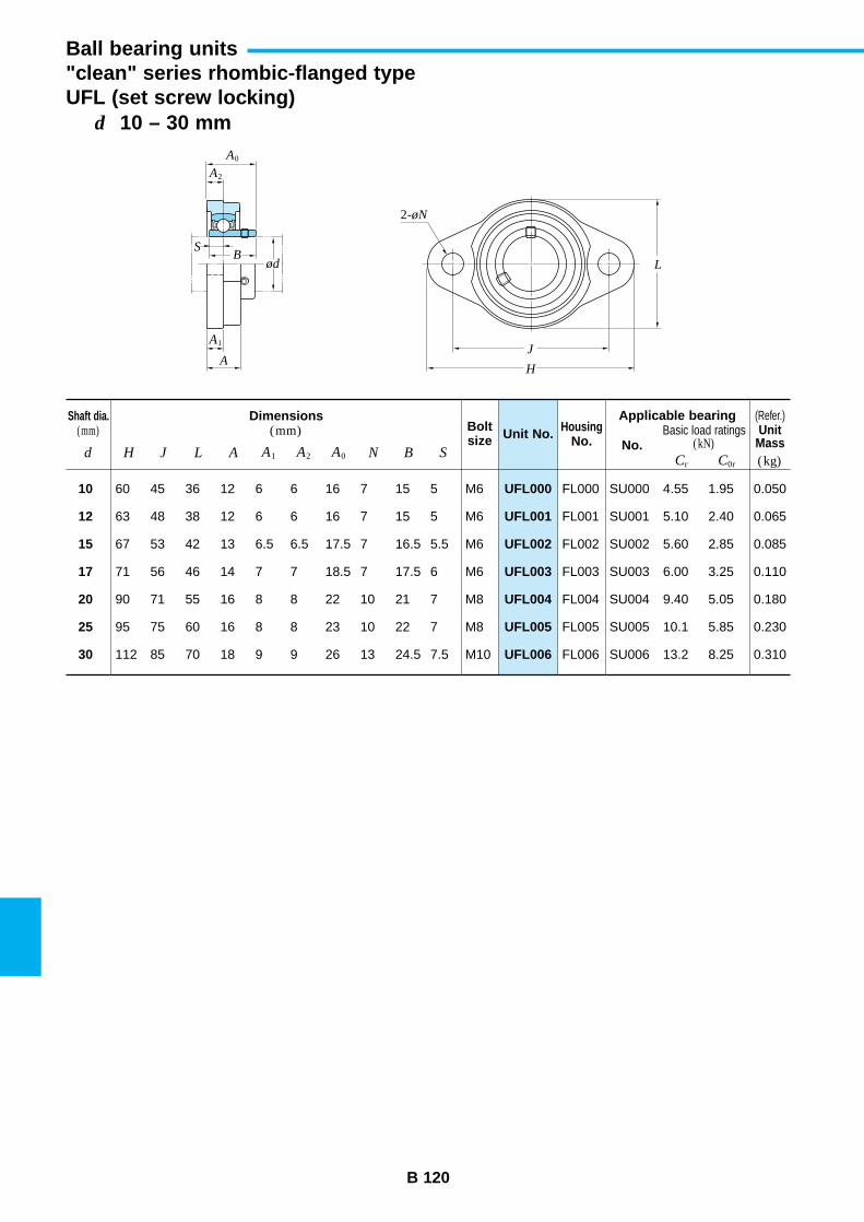
B 120
d 10 – 30 mm
Ball bearing units"clean" series rhombic-flanged typeUFL (set screw locking)
UFL000
UFL001
UFL002
UFL003
UFL004
UFL005
UFL006
Unit No.Shaft dia.
(mm)Dimensions
(mm) Boltsize
HousingNo. No.
d H J L A A1 A2 A0 N B S
Applicable bearingBasic load ratings
(kN)
10
12
15
17
20
25
30
60 45 36 12 6 6 16 7 15 5 M6
63 48 38 12 6 6 16 7 15 5 M6
67 53 42 13 6.5 6.5 17.5 7 16.5 5.5 M6
71 56 46 14 7 7 18.5 7 17.5 6 M6
90 71 55 16 8 8 22 10 21 7 M8
95 75 60 16 8 8 23 10 22 7 M8
112 85 70 18 9 9 26 13 24.5 7.5 M10
FL000 SU000 4.55 1.95 0.050
FL001 SU001 5.10 2.40 0.065
FL002 SU002 5.60 2.85 0.085
FL003 SU003 6.00 3.25 0.110
FL004 SU004 9.40 5.05 0.180
FL005 SU005 10.1 5.85 0.230
FL006 SU006 13.2 8.25 0.310
(Refer.)
(kg)Cr C0r
UnitMass
ød
A1
A
B
A0
A2
S
H
L
J
2-øN
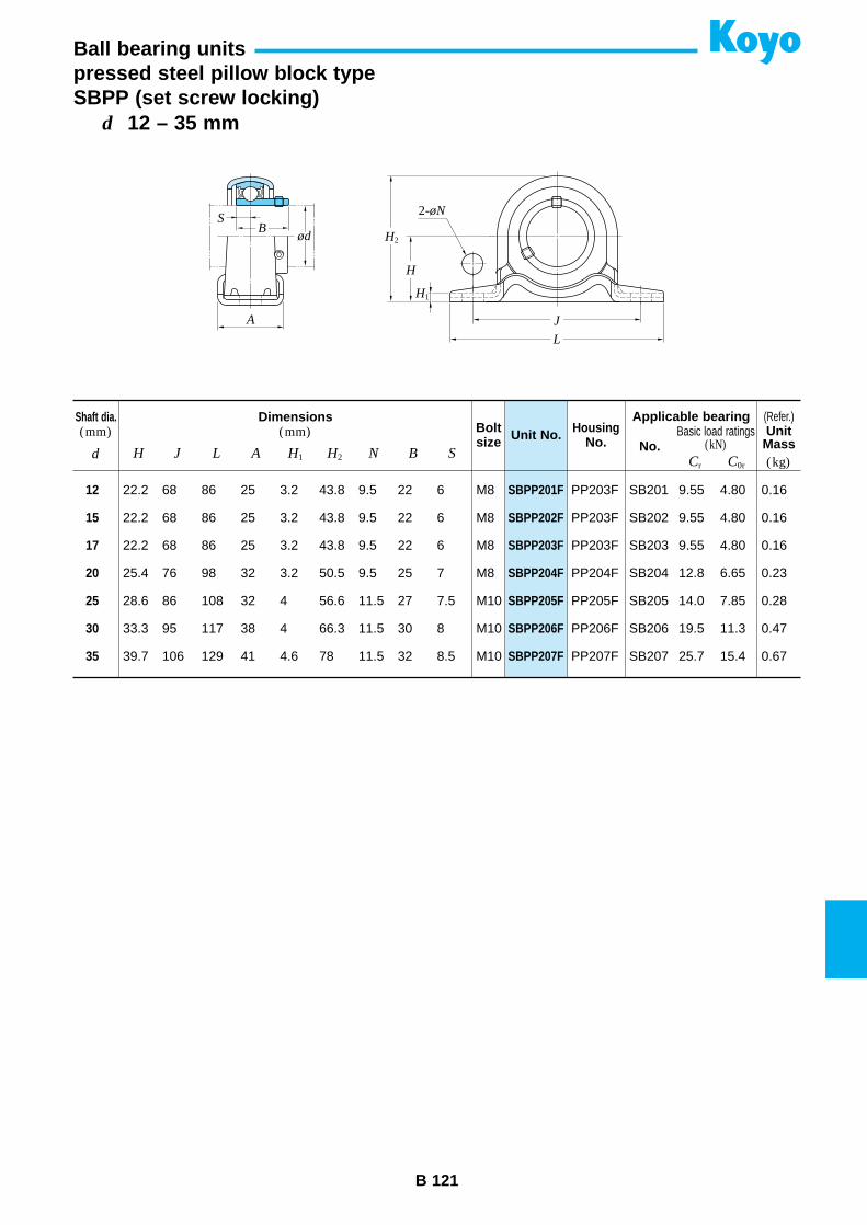
B 121
d 12 – 35 mm
Ball bearing unitspressed steel pillow block typeSBPP (set screw locking)
SBPP201F
SBPP202F
SBPP203F
SBPP204F
SBPP205F
SBPP206F
SBPP207F
Unit No.Shaft dia.(mm)
Dimensions(mm) Bolt
sizeHousing
No. No.d H J L A H1 H2 N B S
Applicable bearingBasic load ratings
(kN)
12
15
17
20
25
30
35
22.2 68 86 25 3.2 43.8 9.5 22 6 M8
22.2 68 86 25 3.2 43.8 9.5 22 6 M8
22.2 68 86 25 3.2 43.8 9.5 22 6 M8
25.4 76 98 32 3.2 50.5 9.5 25 7 M8
28.6 86 108 32 4 56.6 11.5 27 7.5 M10
33.3 95 117 38 4 66.3 11.5 30 8 M10
39.7 106 129 41 4.6 78 11.5 32 8.5 M10
PP203F SB201 9.55 4.80 0.16
PP203F SB202 9.55 4.80 0.16
PP203F SB203 9.55 4.80 0.16
PP204F SB204 12.8 6.65 0.23
PP205F SB205 14.0 7.85 0.28
PP206F SB206 19.5 11.3 0.47
PP207F SB207 25.7 15.4 0.67
(Refer.)
(kg)Cr C0r
UnitMass
BS
ød
A
L
J
H
H2
H1
2-øN
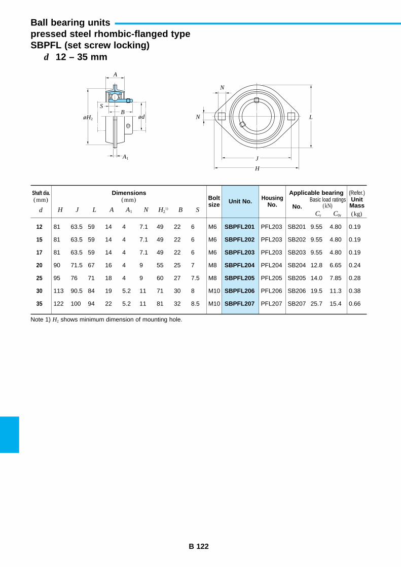
B 122
d 12 – 35 mm
Ball bearing unitspressed steel rhombic-flanged typeSBPFL (set screw locking)
SBPFL201
SBPFL202
SBPFL203
SBPFL204
SBPFL205
SBPFL206
SBPFL207
Unit No.Shaft dia.(mm)
Dimensions(mm) Bolt
sizeHousing
No. No.d H J L A A1 N H2
1) B S
Applicable bearingBasic load ratings
(kN)
12
15
17
20
25
30
35
81 63.5 59 14 4 7.1 49 22 6
81 63.5 59 14 4 7.1 49 22 6
81 63.5 59 14 4 7.1 49 22 6
90 71.5 67 16 4 9 55 25 7
95 76 71 18 4 9 60 27 7.5
113 90.5 84 19 5.2 11 71 30 8
122 100 94 22 5.2 11 81 32 8.5
M6
M6
M6
M8
M8
M10
M10
PFL203 SB201 9.55 4.80 0.19
PFL203 SB202 9.55 4.80 0.19
PFL203 SB203 9.55 4.80 0.19
PFL204 SB204 12.8 6.65 0.24
PFL205 SB205 14.0 7.85 0.28
PFL206 SB206 19.5 11.3 0.38
PFL207 SB207 25.7 15.4 0.66
(Refer.)
(kg)Cr C0r
UnitMass
Note 1) H2 shows minimum dimension of mounting hole.
B
J
L
N
N
H
S
ødøH2
A1
A
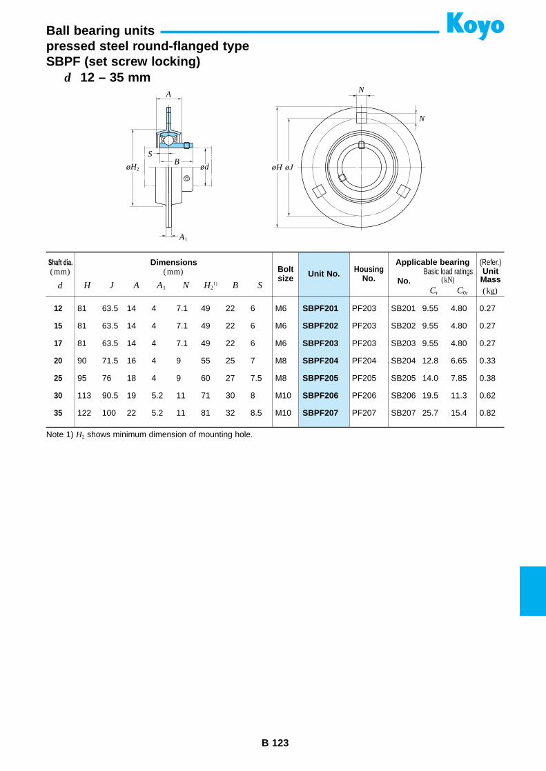
B 123
d 12 – 35 mm
Ball bearing unitspressed steel round-flanged typeSBPF (set screw locking)
SBPF201
SBPF202
SBPF203
SBPF204
SBPF205
SBPF206
SBPF207
Unit No.Shaft dia.(mm)
Dimensions(mm) Bolt
sizeHousing
No. No.d H J A A1 N H2
1) B S
Applicable bearingBasic load ratings
(kN)
12
15
17
20
25
30
35
81 63.5 14 4 7.1 49 22 6
81 63.5 14 4 7.1 49 22 6
81 63.5 14 4 7.1 49 22 6
90 71.5 16 4 9 55 25 7
95 76 18 4 9 60 27 7.5
113 90.5 19 5.2 11 71 30 8
122 100 22 5.2 11 81 32 8.5
M6
M6
M6
M8
M8
M10
M10
PF203 SB201 9.55 4.80 0.27
PF203 SB202 9.55 4.80 0.27
PF203 SB203 9.55 4.80 0.27
PF204 SB204 12.8 6.65 0.33
PF205 SB205 14.0 7.85 0.38
PF206 SB206 19.5 11.3 0.62
PF207 SB207 25.7 15.4 0.82
(Refer.)
(kg)Cr C0r
UnitMass
Note 1) H2 shows minimum dimension of mounting hole.
BS
A1
ød øH øJøH2
AN
N
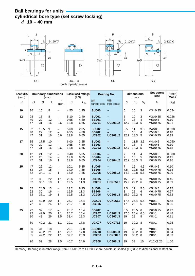
B 124
Ball bearings for unitscylindrical bore type (set screw locking)
d 10 – 40 mm
Boundary dimensions(mm)
Basic load ratings(kN)
Bearing No. Dimensions(mm)
(Refer.)Mass
D B Cr
min. S
Set screwsize
GS1 S2Cr C0rWithstandard seals
Withtriple-lip seals (kg)
10
12
15
17
20
25
30
35
40
SU000 –
SU001 –SB201 –UC201 UC201L2
SU002 –SB202 –UC202 UC202L2
SU003 –SB203 –UC203 UC203L2
SU004 –SB204 –UC204 UC204L2
SU005 –SB205 –UC205 UC205L2
UC305 –UCX05 UCX05L3
SU006 –SB206 –UC206 UC206L3
UCX06 UCX06L3UC306 –
SB207 –UC207 UC207L3UC307 UC307L3
UCX07 UCX07L3
SB208 –UC208 UC208L3UCX08 UCX08L3
UC308 UC308L3
26 15 8 – 4.55 1.95
28 15 8 – 5.10 2.4040 22 12 – 9.55 4.8047 31 16 0.6 12.8 6.65
32 16.5 9 – 5.60 2.8540 22 12 – 9.55 4.8047 31 16 0.6 12.8 6.65
35 17.5 10 – 6.00 3.2540 22 12 – 9.55 4.8047 31 16 0.6 12.8 6.65
42 21 12 – 9.40 5.0547 25 14 – 12.8 6.6547 31 16 1 12.8 6.65
47 22 12 – 10.1 5.8552 27 15 – 14.0 7.8552 34.1 17 1 14.0 7.85
62 38 22 1.1 20.6 11.362 38.1 19 1 19.5 11.3
55 24.5 13 – 13.2 8.2562 30 16 – 19.5 11.362 38.1 19 1 19.5 11.3
72 42.9 20 1 25.7 15.472 43 24 1.1 26.7 15.0
72 32 17 – 25.7 15.472 42.9 20 1.1 25.7 15.480 48 26 1.5 33.4 19.3
80 49.2 21 1.1 29.1 17.8
80 34 18 – 29.1 17.880 49.2 21 1.1 29.1 17.885 49.2 22 1.1 32.7 20.3
90 52 28 1.5 40.7 24.0
5 10 3 M30.35 0.024
5 10 3 M30.35 0.0266 16 4 M50.5 0.1012.7 18.3 5 M60.75 0.21
5.5 11 3.3 M40.5 0.0386 16 4 M50.5 0.1012.7 18.3 5 M60.75 0.19
6 11.5 3.3 M40.5 0.0506 16 4 M50.5 0.1012.7 18.3 5 M60.75 0.18
7 14 4 M50.5 0.0807 18 5 M60.75 0.1512.7 18.3 5 M60.75 0.16
7 15 4.5 M50.5 0.107.5 19.5 5.5 M60.75 0.1814.3 19.8 5.5 M60.75 0.20
15 23 6 M60.75 0.4515.9 22.2 6 M60.75 0.39
7.5 17 5.5 M50.5 0.158 22 6 M60.75 0.2715.9 22.2 6 M60.75 0.32
17.5 25.4 6.5 M81 0.5817 26 6 M60.75 0.56
8.5 23.5 6 M60.75 0.4217.5 25.4 6.5 M81 0.4819 29 8 M81 0.71
19 30.2 8 M81 0.75
9 25 8 M81 0.6019 30.2 8 M81 0.6419 30.2 8 M81 0.83
19 33 10 M101.25 1.00
Remark) Bearing in number range from UC201L2 to UC205L2 are double-lip sealed (L2) due to dimensional restriction.
Shaft dia.(mm)
d
B
C
S S1
S2
SøDød
B
C
S
2-120˚G 2-120˚G 2-120˚G
S1
S2
SøDød
B
C
S S1
S2
SøDød
r
UC UC...L3(with triple-lip seals)
SU SB
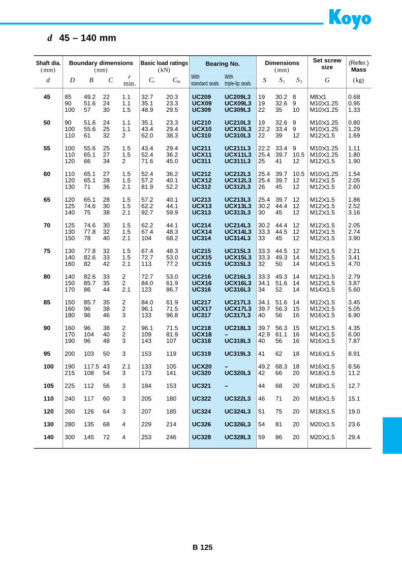
B 125
d 45 – 140 mm
Boundary dimensions(mm)
Basic load ratings(kN)
Bearing No. Dimensions(mm)
(Refer.)Mass
D B Cr
min. S
Set screwsize
GS1 S2Cr C0rWithstandard seals
Withtriple-lip seals (kg)
45
50
55
60
65
70
75
80
85
90
95
100
105
110
120
130
140
UC209 UC209L3UCX09 UCX09L3UC309 UC309L3
UC210 UC210L3UCX10 UCX10L3UC310 UC310L3
UC211 UC211L3UCX11 UCX11L3UC311 UC311L3
UC212 UC212L3UCX12 UCX12L3UC312 UC312L3
UC213 UC213L3UCX13 UCX13L3UC313 UC313L3
UC214 UC214L3UCX14 UCX14L3UC314 UC314L3
UC215 UC215L3UCX15 UCX15L3UC315 UC315L3
UC216 UC216L3UCX16 UCX16L3UC316 UC316L3
UC217 UC217L3UCX17 UCX17L3UC317 UC317L3
UC218 UC218L3UCX18 –UC318 UC318L3
UC319 UC319L3
UCX20 –UC320 UC320L3
UC321 –
UC322 UC322L3
UC324 UC324L3
UC326 UC326L3
UC328 UC328L3
85 49.2 22 1.1 32.7 20.390 51.6 24 1.1 35.1 23.3100 57 30 1.5 48.9 29.5
90 51.6 24 1.1 35.1 23.3100 55.6 25 1.1 43.4 29.4110 61 32 2 62.0 38.3
100 55.6 25 1.5 43.4 29.4110 65.1 27 1.5 52.4 36.2120 66 34 2 71.6 45.0
110 65.1 27 1.5 52.4 36.2120 65.1 28 1.5 57.2 40.1130 71 36 2.1 81.9 52.2
120 65.1 28 1.5 57.2 40.1125 74.6 30 1.5 62.2 44.1140 75 38 2.1 92.7 59.9
125 74.6 30 1.5 62.2 44.1130 77.8 32 1.5 67.4 48.3150 78 40 2.1 104 68.2
130 77.8 32 1.5 67.4 48.3140 82.6 33 1.5 72.7 53.0160 82 42 2.1 113 77.2
140 82.6 33 2 72.7 53.0150 85.7 35 2 84.0 61.9170 86 44 2.1 123 86.7
150 85.7 35 2 84.0 61.9160 96 38 2 96.1 71.5180 96 46 3 133 96.8
160 96 38 2 96.1 71.5170 104 40 2 109 81.9190 96 48 3 143 107
200 103 50 3 153 119
190 117.5 43 2.1 133 105215 108 54 3 173 141
225 112 56 3 184 153
240 117 60 3 205 180
260 126 64 3 207 185
280 135 68 4 229 214
300 145 72 4 253 246
19 30.2 8 M81 0.6819 32.6 9 M101.25 0.9522 35 10 M101.25 1.33
19 32.6 9 M101.25 0.8022.2 33.4 9 M101.25 1.2922 39 12 M121.5 1.69
22.2 33.4 9 M101.25 1.1125.4 39.7 10.5 M101.25 1.8025 41 12 M121.5 1.90
25.4 39.7 10.5 M101.25 1.5425.4 39.7 12 M121.5 2.0526 45 12 M121.5 2.60
25.4 39.7 12 M121.5 1.8630.2 44.4 12 M121.5 2.5230 45 12 M121.5 3.16
30.2 44.4 12 M121.5 2.0533.3 44.5 12 M121.5 2.7433 45 12 M121.5 3.90
33.3 44.5 12 M121.5 2.2133.3 49.3 14 M121.5 3.4132 50 14 M141.5 4.70
33.3 49.3 14 M121.5 2.7934.1 51.6 14 M121.5 3.8734 52 14 M141.5 5.60
34.1 51.6 14 M121.5 3.4539.7 56.3 15 M121.5 5.0540 56 16 M161.5 6.90
39.7 56.3 15 M121.5 4.3542.9 61.1 16 M141.5 6.0040 56 16 M161.5 7.87
41 62 18 M161.5 8.91
49.2 68.3 18 M161.5 8.5642 66 20 M181.5 11.2
44 68 20 M181.5 12.7
46 71 20 M181.5 15.1
51 75 20 M181.5 19.0
54 81 20 M201.5 23.6
59 86 20 M201.5 29.4
Shaft dia.(mm)
d
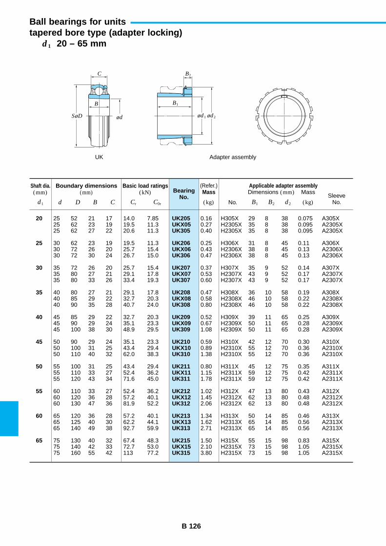
B 126
Ball bearings for unitstapered bore type (adapter locking)
d1 20 – 65 mm
Boundary dimensions(mm)
Basic load ratings(kN) Bearing
No.
Applicable adapter assemblyDimensions (mm) Mass
SleeveNo.
(Refer.)Mass
No.d D B C B1 (kg)B2 d2Cr C0r (kg)
20
25
30
35
40
45
50
55
60
65
UK205UKX05UK305
UK206UKX06UK306
UK207UKX07UK307
UK208UKX08UK308
UK209UKX09UK309
UK210UKX10UK310
UK211UKX11UK311
UK212UKX12UK312
UK213UKX13UK313
UK215UKX15UK315
25 52 21 17 14.0 7.8525 62 23 19 19.5 11.325 62 27 22 20.6 11.3
30 62 23 19 19.5 11.330 72 26 20 25.7 15.430 72 30 24 26.7 15.0
35 72 26 20 25.7 15.435 80 27 21 29.1 17.835 80 33 26 33.4 19.3
40 80 27 21 29.1 17.840 85 29 22 32.7 20.340 90 35 28 40.7 24.0
45 85 29 22 32.7 20.345 90 29 24 35.1 23.345 100 38 30 48.9 29.5
50 90 29 24 35.1 23.350 100 31 25 43.4 29.450 110 40 32 62.0 38.3
55 100 31 25 43.4 29.455 110 33 27 52.4 36.255 120 43 34 71.6 45.0
60 110 33 27 52.4 36.260 120 36 28 57.2 40.160 130 47 36 81.9 52.2
65 120 36 28 57.2 40.165 125 40 30 62.2 44.165 140 49 38 92.7 59.9
75 130 40 32 67.4 48.375 140 42 33 72.7 53.075 160 55 42 113 77.2
0.16 H305X 29 8 38 0.075 A305X0.27 H2305X 35 8 38 0.095 A2305X0.40 H2305X 35 8 38 0.095 A2305X
0.25 H306X 31 8 45 0.11 A306X0.43 H2306X 38 8 45 0.13 A2306X0.47 H2306X 38 8 45 0.13 A2306X
0.37 H307X 35 9 52 0.14 A307X0.53 H2307X 43 9 52 0.17 A2307X0.60 H2307X 43 9 52 0.17 A2307X
0.47 H308X 36 10 58 0.19 A308X0.58 H2308X 46 10 58 0.22 A2308X0.80 H2308X 46 10 58 0.22 A2308X
0.52 H309X 39 11 65 0.25 A309X0.67 H2309X 50 11 65 0.28 A2309X1.08 H2309X 50 11 65 0.28 A2309X
0.59 H310X 42 12 70 0.30 A310X0.89 H2310X 55 12 70 0.36 A2310X1.38 H2310X 55 12 70 0.36 A2310X
0.80 H311X 45 12 75 0.35 A311X1.15 H2311X 59 12 75 0.42 A2311X1.78 H2311X 59 12 75 0.42 A2311X
1.02 H312X 47 13 80 0.43 A312X1.45 H2312X 62 13 80 0.48 A2312X2.06 H2312X 62 13 80 0.48 A2312X
1.34 H313X 50 14 85 0.46 A313X1.62 H2313X 65 14 85 0.56 A2313X2.71 H2313X 65 14 85 0.56 A2313X
1.50 H315X 55 15 98 0.83 A315X2.10 H2315X 73 15 98 1.05 A2315X3.80 H2315X 73 15 98 1.05 A2315X
Shaft dia.(mm)
d1
C B2
B1B
SøD ød ød1 ød2
UK Adapter assembly
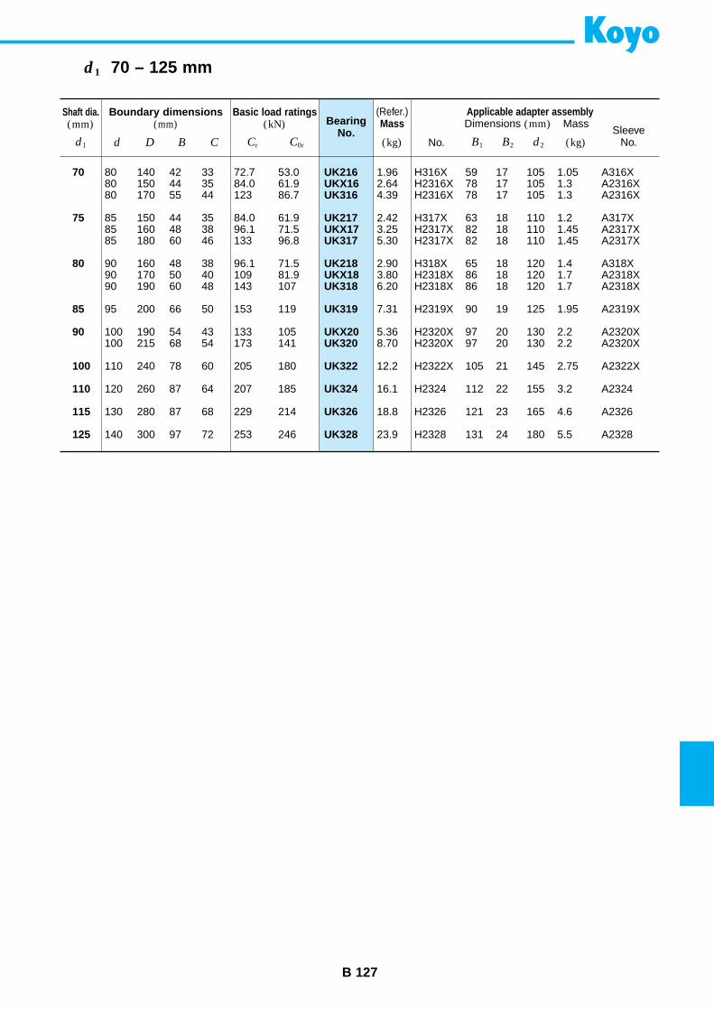
B 127
d1 70 – 125 mm
Boundary dimensions(mm)
Basic load ratings(kN) Bearing
No.
Applicable adapter assemblyDimensions (mm) Mass
SleeveNo.
(Refer.)Mass
No.d D B C B1 (kg)B2 d2Cr C0r (kg)
70
75
80
85
90
100
110
115
125
UK216UKX16UK316
UK217UKX17UK317
UK218UKX18UK318
UK319
UKX20UK320
UK322
UK324
UK326
UK328
80 140 42 33 72.7 53.080 150 44 35 84.0 61.980 170 55 44 123 86.7
85 150 44 35 84.0 61.985 160 48 38 96.1 71.585 180 60 46 133 96.8
90 160 48 38 96.1 71.590 170 50 40 109 81.990 190 60 48 143 107
95 200 66 50 153 119
100 190 54 43 133 105100 215 68 54 173 141
110 240 78 60 205 180
120 260 87 64 207 185
130 280 87 68 229 214
140 300 97 72 253 246
1.96 H316X 59 17 105 1.05 A316X2.64 H2316X 78 17 105 1.3 A2316X4.39 H2316X 78 17 105 1.3 A2316X
2.42 H317X 63 18 110 1.2 A317X3.25 H2317X 82 18 110 1.45 A2317X5.30 H2317X 82 18 110 1.45 A2317X
2.90 H318X 65 18 120 1.4 A318X3.80 H2318X 86 18 120 1.7 A2318X6.20 H2318X 86 18 120 1.7 A2318X
7.31 H2319X 90 19 125 1.95 A2319X
5.36 H2320X 97 20 130 2.2 A2320X8.70 H2320X 97 20 130 2.2 A2320X
12.2 H2322X 105 21 145 2.75 A2322X
16.1 H2324 112 22 155 3.2 A2324
18.8 H2326 121 23 165 4.6 A2326
23.9 H2328 131 24 180 5.5 A2328
Shaft dia.(mm)
d1
Bearings are often fit to a shaft with an adaptersleeve, locknut, lockwasher or lock plate.
These accessories make it easy to attach and removebearings.
They are standardized in JIS.
• Locknuts are standardized such that they can beused with either adapter sleeves, withdrawal sleevesor shafts.
• Lockwashers and lock plates are used as locks onlocknuts.
Lockwashers are used with bearings of bore diameternumber 40 or lower. Lock plates are used with those ofbore diameter 44 or higher.
B 129
Locknuts and lockwashers Locknuts
AN 02 – 100
Lockwashers
AW 00 - 40 (X)
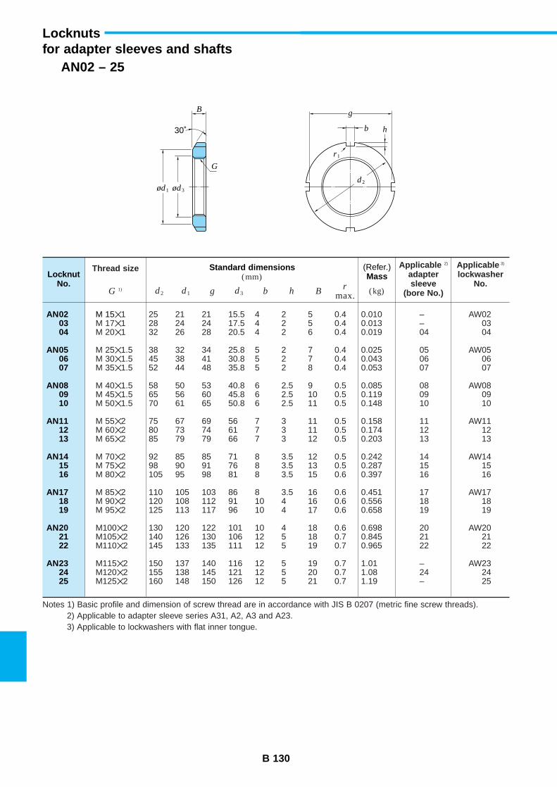
B 130
AN02 – 25
Locknutsfor adapter sleeves and shafts
Standard dimensions(mm)
Thread size Applicable 2)
adaptersleeve
(bore No.)
Applicable 3)
lockwasherNo.
LocknutNo.
(Refer.)Mass
d2 d1 g d3 b h Br
max. (kg)G 1)
AN020304
AN050607
AN080910
AN111213
AN141516
AN171819
AN202122
AN232425
M 151 25 21 21 15.5 4 2 5 0.4 0.010 – AW02M 171 28 24 24 17.5 4 2 5 0.4 0.013 – 03M 201 32 26 28 20.5 4 2 6 0.4 0.019 04 04
M 251.5 38 32 34 25.8 5 2 7 0.4 0.025 05 AW05M 301.5 45 38 41 30.8 5 2 7 0.4 0.043 06 06M 351.5 52 44 48 35.8 5 2 8 0.4 0.053 07 07
M 401.5 58 50 53 40.8 6 2.5 9 0.5 0.085 08 AW08M 451.5 65 56 60 45.8 6 2.5 10 0.5 0.119 09 09M 501.5 70 61 65 50.8 6 2.5 11 0.5 0.148 10 10
M 552 75 67 69 56 7 3 11 0.5 0.158 11 AW11M 602 80 73 74 61 7 3 11 0.5 0.174 12 12M 652 85 79 79 66 7 3 12 0.5 0.203 13 13
M 702 92 85 85 71 8 3.5 12 0.5 0.242 14 AW14M 752 98 90 91 76 8 3.5 13 0.5 0.287 15 15M 802 105 95 98 81 8 3.5 15 0.6 0.397 16 16
M 852 110 105 103 86 8 3.5 16 0.6 0.451 17 AW17M 902 120 108 112 91 10 4 16 0.6 0.556 18 18M 952 125 113 117 96 10 4 17 0.6 0.658 19 19
M1002 130 120 122 101 10 4 18 0.6 0.698 20 AW20M1052 140 126 130 106 12 5 18 0.7 0.845 21 21M1102 145 133 135 111 12 5 19 0.7 0.965 22 22
M1152 150 137 140 116 12 5 19 0.7 1.01 – AW23M1202 155 138 145 121 12 5 20 0.7 1.08 24 24M1252 160 148 150 126 12 5 21 0.7 1.19 – 25
Notes 1) Basic profile and dimension of screw thread are in accordance with JIS B 0207 (metric fine screw threads).2) Applicable to adapter sleeve series A31, A2, A3 and A23.3) Applicable to lockwashers with flat inner tongue.
Bg
b
G
r1
h30˚
ød1
d2ød3
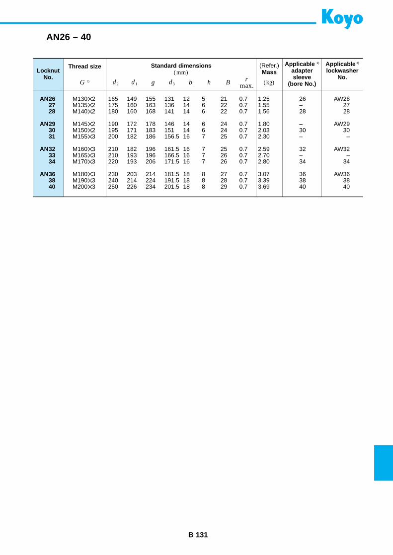
B 131
AN26 – 40
Standard dimensions(mm)
Thread size Applicable 2)
adaptersleeve
(bore No.)
Applicable 3)
lockwasherNo.
LocknutNo.
(Refer.)Mass
d2 d1 g d3 b h Br
max. (kg)G 1)
AN262728
AN293031
AN323334
AN363840
M1302 165 149 155 131 12 5 21 0.7 1.25 26 AW26M1352 175 160 163 136 14 6 22 0.7 1.55 – 27M1402 180 160 168 141 14 6 22 0.7 1.56 28 28
M1452 190 172 178 146 14 6 24 0.7 1.80 – AW29M1502 195 171 183 151 14 6 24 0.7 2.03 30 30M1553 200 182 186 156.5 16 7 25 0.7 2.30 – –
M1603 210 182 196 161.5 16 7 25 0.7 2.59 32 AW32M1653 210 193 196 166.5 16 7 26 0.7 2.70 – –M1703 220 193 206 171.5 16 7 26 0.7 2.80 34 34
M1803 230 203 214 181.5 18 8 27 0.7 3.07 36 AW36M1903 240 214 224 191.5 18 8 28 0.7 3.39 38 38M2003 250 226 234 201.5 18 8 29 0.7 3.69 40 40
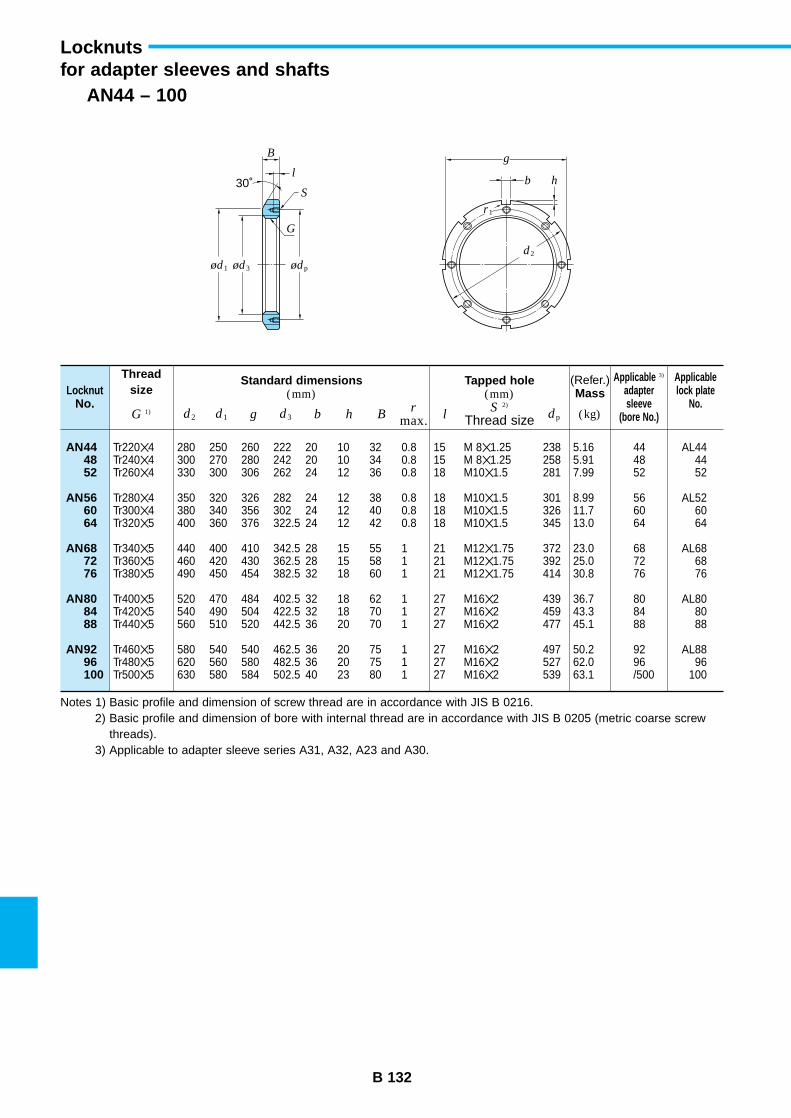
B 132
AN44 – 100
Locknutsfor adapter sleeves and shafts
Standard dimensions(mm)
Tapped hole(mm)
Threadsize
Applicable 3)
adaptersleeve
(bore No.)
Applicablelock plate
No.Locknut
No.
(Refer.)Mass
d2 d1 g d3 b h Br
max. lS 2)
Thread size dp (kg)G 1)
AN444852
AN566064
AN687276
AN808488
AN9296100
Tr2204 280 250 260 222 20 10 32 0.8 15 M 81.25 238 5.16 44 AL44Tr2404 300 270 280 242 20 10 34 0.8 15 M 81.25 258 5.91 48 44Tr2604 330 300 306 262 24 12 36 0.8 18 M101.5 281 7.99 52 52
Tr2804 350 320 326 282 24 12 38 0.8 18 M101.5 301 8.99 56 AL52Tr3004 380 340 356 302 24 12 40 0.8 18 M101.5 326 11.7 60 60Tr3205 400 360 376 322.5 24 12 42 0.8 18 M101.5 345 13.0 64 64
Tr3405 440 400 410 342.5 28 15 55 1 21 M121.75 372 23.0 68 AL68Tr3605 460 420 430 362.5 28 15 58 1 21 M121.75 392 25.0 72 68Tr3805 490 450 454 382.5 32 18 60 1 21 M121.75 414 30.8 76 76
Tr4005 520 470 484 402.5 32 18 62 1 27 M162 439 36.7 80 AL80Tr4205 540 490 504 422.5 32 18 70 1 27 M162 459 43.3 84 80Tr4405 560 510 520 442.5 36 20 70 1 27 M162 477 45.1 88 88
Tr4605 580 540 540 462.5 36 20 75 1 27 M162 497 50.2 92 AL88Tr4805 620 560 580 482.5 36 20 75 1 27 M162 527 62.0 96 96Tr5005 630 580 584 502.5 40 23 80 1 27 M162 539 63.1 /500 100
Notes 1) Basic profile and dimension of screw thread are in accordance with JIS B 0216.2) Basic profile and dimension of bore with internal thread are in accordance with JIS B 0205 (metric coarse screw
threads).3) Applicable to adapter sleeve series A31, A32, A23 and A30.
B
l
g
r1
b
G
h30˚
ød1
d2
ød3 ødp
S
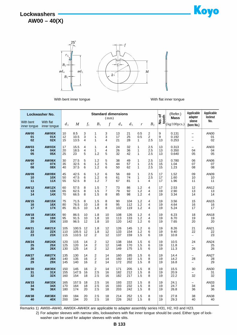
Lockwasher No.
With bentinner tongue
With flatinner tongue
B 133
Lockwashers
Standard dimensions(mm)
No.
ofto
oth
Applicableadaptersleeve
(bore No.)
Applicablelocknut
No.
(Refer.)Mass
d3 M f1 B1 f d4 d5 r B2 (kg/100pcs.)
AW00 AW00X01 01X02 02X
AW03 AW03X04 04X05 05X
AW06 AW06X07 07X08 08X
AW09 AW09X10 10X11 11X
AW12 AW12X13 13X14 14X
AW15 AW15X16 16X17 17X
AW18 AW18X19 19X20 20X
AW21 AW21X22 22X23 23X
AW24 AW24X25 25X26 26X
AW27 AW27X28 28X29 29X
AW30 AW30X31 31X32 32X
AW33 AW33X34 34X36 36X
AW38 AW38X40 40X
10 8.5 3 1 3 13 21 0.5 2 9 0.131 – AN0012 10.5 3 1 3 17 25 0.5 2 9 0.192 – 0115 13.5 4 1 4 21 28 1 2.5 13 0.253 – 02
17 15.5 4 1 4 24 32 1 2.5 13 0.313 – AN0320 18.5 4 1 4 26 36 1 2.5 13 0.350 04 0425 23 5 1.2 5 32 42 1 2.5 13 0.640 05 05
30 27.5 5 1.2 5 38 49 1 2.5 13 0.780 06 AN0635 32.5 6 1.2 5 44 57 1 2.5 15 1.04 07 0740 37.5 6 1.2 6 50 62 1 2.5 15 1.23 08 08
45 42.5 6 1.2 6 56 69 1 2.5 17 1.52 09 AN0950 47.5 6 1.2 6 61 74 1 2.5 17 1.60 10 1055 52.5 8 1.2 7 67 81 1 4 17 1.96 11 11
60 57.5 8 1.5 7 73 86 1.2 4 17 2.53 12 AN1265 62.5 8 1.5 7 79 92 1.2 4 19 2.90 13 1370 66.5 8 1.5 8 85 98 1.2 4 19 3.34 14 14
75 71.5 8 1.5 8 90 104 1.2 4 19 3.56 15 AN1580 76.5 10 1.8 8 95 112 1.2 4 19 4.64 16 1685 81.5 10 1.8 8 102 119 1.2 4 19 5.24 17 17
90 86.5 10 1.8 10 108 126 1.2 4 19 6.23 18 AN1895 91.5 10 1.8 10 113 133 1.2 4 19 6.70 19 19100 96.5 12 1.8 10 120 142 1.2 6 19 7.65 20 20
105 100.5 12 1.8 12 126 145 1.2 6 19 8.26 21 AN21110 105.5 12 1.8 12 133 154 1.2 6 19 9.40 22 22115 110.5 12 2 12 137 159 1.5 6 19 10.8 – 23
120 115 14 2 12 138 164 1.5 6 19 10.5 24 AN24125 120 14 2 12 148 170 1.5 6 19 11.8 – 25130 125 14 2 12 149 175 1.5 6 19 11.3 26 26
135 130 14 2 14 160 185 1.5 6 19 14.4 – AN27140 135 16 2 14 160 192 1.5 8 19 14.2 28 28145 140 16 2 14 172 202 1.5 8 19 16.8 – 29
150 145 16 2 14 171 205 1.5 8 19 15.5 30 AN30155 147.5 16 2.5 16 182 212 1.5 8 19 20.9 – 31160 154 18 2.5 16 182 217 1.5 8 19 22.2 32 32
165 157.5 18 2.5 16 193 222 1.5 8 19 24.1 – AN33170 164 18 2.5 16 193 232 1.5 8 19 24.7 34 34180 174 20 2.5 18 203 242 1.5 8 19 26.8 36 36
190 184 20 2.5 18 214 252 1.5 8 19 27.8 38 AN38200 194 20 2.5 18 226 262 1.5 8 19 29.3 40 40
Remarks 1) AW00–AW40, AW00X–AW40X are applicable to adapter assembly series H31, H2, H3 and H23.2) For adapter sleeves with narrow slits, lockwashers with flat inner tongue should be used. Either type of lock-
washer can be used for adapter sleeves with wide slits.
AW00 – 40(X)
f
M
f1
d3
25˚
ød4 ød5
B2
B1
r2
With bent inner tongue With flat inner tongue
C 1
Supplementary tables
Contents
1. Shaft tolerances (deviation from nominal dimensions) ................... C 2
2. Housing bore tolerances (deviation from nominal dimensions) ..... C 4
3. Numerical values for standard tolerance grades IT ......................... C 6
4. Greek alphabet list ............................................................................... C 7
5. Prefixes used with SI units .................................................................. C 7
6. SI units and conversion factors .......................................................... C 8
7. Inch/millimeter conversion .................................................................. C12
8. Steel hardness conversion .................................................................. C13
9. Surface roughness comparison .......................................................... C14
10. Viscosity conversion ............................................................................ C15
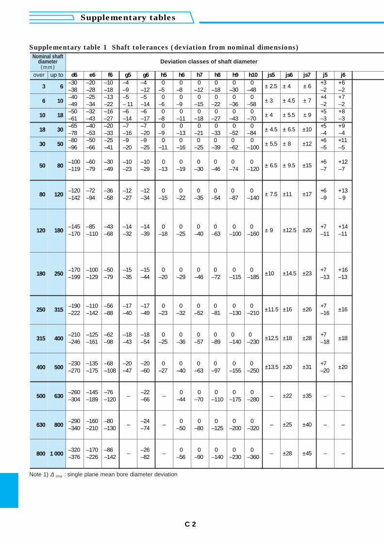
C 2
Supplementary tables
Nominal shaftdiameter(mm)
Deviation classes of shaft diameter
over up to d6 e6 f6 g5 g6 h5 h6 h7 h8 h9 h10 js5 js6 js7 j5 j6–30 –20 –10 –4 –4 0 0 0 0 0 0 ± 2.5 ± 4 ± 6 +3 +6
3 6 –38 –28 –18 –9 –12 –5 –8 –12 –18 –30 –48 –2 –2–40 –25 –13 –5 –5 0 0 0 0 0 0 ± 3 ± 4.5 ± 7 +4 +7
6 10 –49 –34 –22 – 11 –14 –6 –9 –15 –22 –36 –58 –2 –2–50 –32 –16 –6 –6 0 0 0 0 0 0 ± 4 ± 5.5 ± 9 +5 +8
10 18 –61 –43 –27 –14 –17 –8 –11 –18 –27 –43 –70 –3 –3
18 30–65 –40 –20 –7 –7 0 0 0 0 0 0 ± 4.5 ± 6.5 ±10 +5 +9–78 –53 –33 –16 –20 –9 –13 –21 –33 –52 –84 –4 –4
30 50–80 –25 –9 –9 0 0 0 0 0 0 ± 5.5 ± 8 ±12 +6 +11–96 –66
–50–41 –20 –25 –11 –16 –25 –39 –62 –100 –5 –5
50 80 ± 6.5 ± 9.5 ±15–100 –60 –30 –10 –10 0 0 0 0 0 0 +6 +12–119 –79 –49 –23 –29 –13 –19 –30 –46 –74 –120 –7 –7
80 120 ± 7.5 ±11 ±17–120 –72 –36 –12 –12 0 0 0 0 0 0 +6 +13–142 –94 –58 –27 –34 –15 –22 –35 –54 –87 –140 –9 – 9
120 180 ± 9 ±12.5 ±20–145 –85 –43 –14 –14 0 0 0 0 0 0 +7 +14–170 –110 –68 –32 –39 –18 –25 –40 –63 –100 –160 –11 –11
180 250 ±10 ±14.5 ±23–170 –100 –50 –15 –15 0 0 0 0 0 0 +7 +16–199 –129 –79 –35 –44 –20 –29 –46 –72 –115 –185 –13 –13
250 315 ±11.5 ±16 ±26 ±16–190 –110 –56 –17 –17 0 0 0 0 0 0 +7–222 –142 –88 –40 –49 –23 –32 –52 –81 –130 –210 –16
315 400 ±12.5 ±18 ±28 ±18–210 –125 –62 –18 –18 0 0 0 0 0 0 +7–246 –161 –98 –43 –54 –25 –36 –57 –89 –140 –230 –18
400 500 ±13.5 ±20 ±31 ±20–230 –135 –68 –20 –20 0 0 0 0 0 0 +7–270 –175 –108 –47 –60 –27 –40 –63 –97 –155 –250 –20
500 630 – – – ±22 ±35 – ––260 –145 –76 –22 0 0 0 0 0–304 –189 –120 –66 –44 –70 –110 –175 –280
630 800 – – – ±25 ±40 – ––290 –160 –80 –24 0 0 0 0 0–340 –210 –130 –74 –50 –80 –125 –200 –320
800 1 000 – – – ±28 ±45 – ––320 –170 –86 –26 0 0 0 0 0–376 –226 –142 –82 –56 –90 –140 –230 –360
Supplementary table 1 Shaft tolerances (deviation from nominal dimensions)
Note 1) ∆ dmp : single plane mean bore diameter deviation
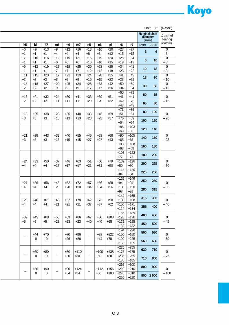
C 3
k5 k6 k7 m5 m6 m7 n5 n6 p6 r6 r7+6 +9 +13 +9 +12 +16 +13 +16 +20 +23 +27+1 +1 +1 +4 +4 +4 +8 +8 +12 +15 +15+7 +10 +16 +12 +15 +21 +16 +19 +24 +28 +34+1 +1 +1 +6 +6 +6 +10 +10 +15 +19 +19+9 +12 +19 +15 +18 +25 +20 +23 +29 +34 +41+1 +1 +1 +7 +7 +7 +12 +12 +18 +23 +23+11 +15 +23 +17 +21 +29 +24 +28 +35 +41 +49+2 +2 +2 +8 +8 +8 +15 +15 +22 +28 +28+13 +18 +27 +20 +25 +34 +28 +33 +42 +50 +59+2 +2 +2 +9 +9 +9 +17 +17 +26 +34 +34
+60 +71+15 +21 +32 +24 +30 +41 +33 +39 +51 +41 +41+2 +2 +2 +11 +11 +11 +20 +20 +32 +62 +73
+43 +43+73 +86
+18 +25 +38 +28 +35 +48 +38 +45 +59 +51 +51+3 +3 +3 +13 +13 +13 +23 +23 +37 +76 +89
+54 +54+88 +103
+21 +28 +43 +33 +40 +55 +45 +52+63
+105+3 +3 +3 +15 +15 +15 +27 +27 +43
+90+63
+68+65 +65+93 +108+68 + 68
+106 +123
+24 +33 +50 +37 +46 +60+77 +77
+4 +4 +4 +17 +17 +17 +31 +31 +50+109 +126+63 +51 +79+80 +80+113 +130+84 +84+126 +146
+27 +36 +56 +43 +52 +72 +57 +66 +88 +94 +94+4 +4 +4 +20 +20 +20 +34 +34 +56 +130 +150
+98 +98+144 +165
+29 +40 +61 +46 +57 +78 +62 +73 +98 +108 +108+4 +4 +4 +21 +21 +21 +37 +37 +62 +150 +171
+114 +114+166 +189
+32 +45 +68 +50 +63 +86 +67 +80 +108 +126 +126+5 +5 +5 +23 +23 +23 +40 +40 +68 +172 +195
+132 +132
– – –
+194 +220+44 +70 +70 +88 +122 +150 +150
0 0 +26 +44 +78 +199 +225+155 +155
– – –
+225 +255+50 +80 +80 +100 +138 +175 +175
0 0 +30 +50 +88 +235 +265+185 +185
– – –
+266 +300+56 +90 +90 +112 +156 +210 +210
0 0 +34 +56 +100 +276 +310+220 +220
Nominal shaftdiameter(mm)
∆ dmp 1) ofbearing(class 0)over up to
3 60
– 8
6 100
– 8
10 180
– 8
18 300
– 10
30 500
– 12
50 65 0– 15
80 100 0– 20
120 140
0– 25
180 200
0– 30
250 280 0– 35
315 355 0– 40
400 450 0– 45
500 560 0– 50
630 710 0– 75
800 900 0– 100
65 80
100 120
140 160
160 180
200 225
225 250
280 315
355 400
450 500
+96+26
560 630
+110+30
710 800
+124+34
900 1 000
Unit µm (Refer.)
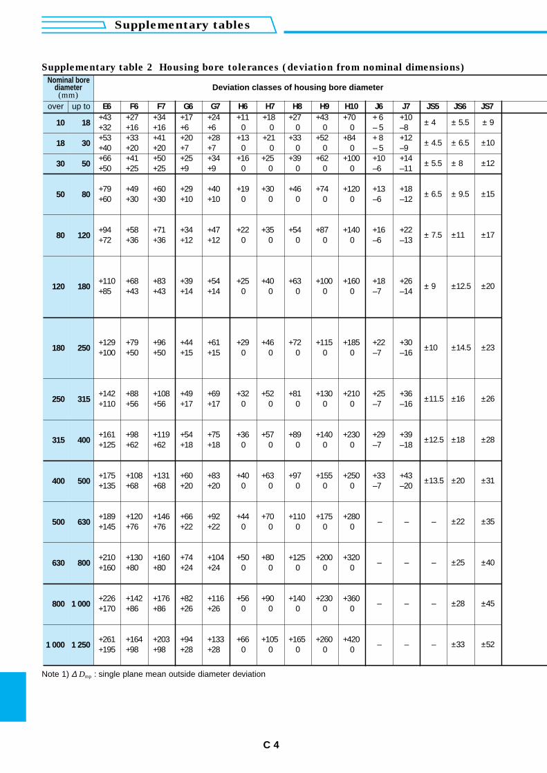
C 4
Supplementary tables
Nominal borediameter(mm)
Deviation classes of housing bore diameter
over up to E6 F6 F7 G6 G7 H6 H7 H8 H9 H10 J6 J7 JS5 JS6 JS7+43 +27 +34 +17 +24 +11 +18 +27 +43 +70 + 6 +10 ± 4 ± 5.5 ± 910 18 +32 +16 +16 +6 +6 0 0 0 0 0+53 +33 +41 +20 +28 +13 +21 +33 +52 +84 + 8 +12 ± 4.5 ± 6.5 ±1018 30 +40 +20 +20 +7 +7 0 0 0 0 0+66 +41 +50 +25 +34 +16 +25 +39 +62 +100 +10 +14 ± 5.5 ± 8 ±1230 50 +50 +25 +25 +9 +9 0 0 0 0 0
50 80 ± 6.5 ± 9.5 ±15+79 +49 +60 +29 +40 +19 +30 +46 +74 +120+60 +30 +30 +10 +10 0 0 0 0 0 –6 –12
80 120 ± 7.5 ±11 ±17+94 +58 +71 +34 +47 +22 +35 +54 +87 +140+72 +36 +36 +12 +12 0 0 0 0 0
120 180 ± 9 ±12.5 ±20+110 +68 +83 +39 +54 +25 +40 +63 +100 +160+85 +43 +43 +14 +14 0 0 0 0 0
±14.5 ±23+129 +79 +96 +44 +61 +29 +46 +72 +115 +185+100 +50 +50 +15 +15 0 0 0 0 0180 250 ±10
±16 ±26+142 +88 +108 +49 +69 +32 +52 +81 +130 +210+110 +56 +56 +17 +17 0 0 0 0 0
315 400 ±12.5 ±18 ±28+161 +98 +119 +54 +75 +36 +57 +89 +140 +230+125 +62 +62 +18 +18 0 0 0 0 0
400 500 ±13.5 ±20 ±31+175 +108 +131 +60 +83 +40 +63 +97 +155 +250+135 +68 +68 +20 +20 0 0 0 0 0
500 630 – – – ±22 ±35+189 +120 +146 +66 +92 +44 +70 +110 +175 +280+145 +76 +76 +22 +22 0 0 0 0 0
630 800 – – – ±25 ±40+210 +130 +160 +104 +80 +125 +200 +320+160 +80 +80 +24 0 0 0 0
800 1 000 – – – ±28 ±45+226 +142 +176 +116 +90 +140 +230 +360+170 +86 +86 +26 0 0 0 0
1 000 1 250 – – – ±33 ±52+261 +164 +203 +133 +105 +165 +260 +420+195 +98 +98 +28 0 0 0 0
– 5 –8
– 5 –9
–6 –11
+13 +18
+16 +22–6 –13
+18 +26–7 –14
+22 +30–7 –16
250 315 ±11.5+25 +36–7 –16
+29 +39–7 –18
+33 +43–7 –20
+74 +50+24 0
+82 +56+26 0
+94 +66+28 0
Supplementary table 2 Housing bore tolerances (deviation from nominal dimensions)
Note 1) ∆ Dmp : single plane mean outside diameter deviation
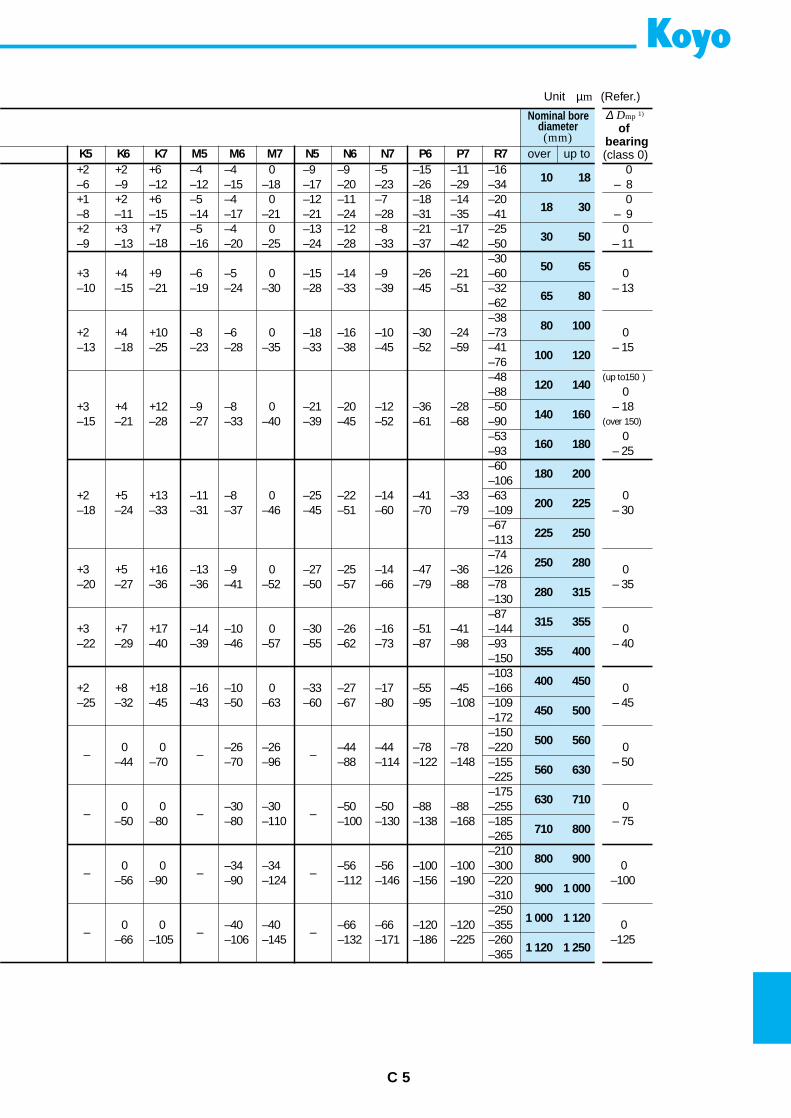
C 5
K5 K6 K7 M5 M6 M7 N5 N6 N7 P6 R7+2 +2 +6 –4 –4 0 –9 –9 –5 –15 –16–6 –9 –12 –12 –15 –18 –17 –20 –23 –26 –34+1 +2 +6 –5 –4 0 –12 –11 –7 –18 –20–8 –11 –15 –14 –17 –21 –21 –24 –28 –31 –41+2 +3 +7 –5 –4 0 –13 –12 –8 –21 –25–9 –13 –18 –16 –20 –25 –24 –28 –33 –37 –50
–30+3 +4 +9 –6 –5 0 –15 –14 –9 –26 –60–10 –15 –21 –19 –24 –30 –28 –33 –39 –45 –32
–62–38
+2 +4 +10 –8 –6 0 –18 –16 –10 –30 –73–13 –18 –25 –23 –28 –35 –33 –38 –45 –52 –41
–76–48–88
+3 +4 +12 –9 –8 0 –21 –20 –12 –36 –50–15 –21 –28 –27 –33 –40 –39 –45 –52 –61 –90
–53
–60–93
–106+2 +5 +13 –11 –8 0 –25 –22 –14 –41 –63–18 –24 –33 –31 –37 –46 –45 –51 –60 –70 –109
–67–113
+3 +5 +16 –13 –9 0 –27 –25 –14–74
–47 –126–20 –27 –36 –36 –41 –52 –50 –57 –66 –79 –78
–130–87
+3 +7 +17 –14 –10 0 –30 –26 –16 –51 –144–22 –29 –40 –39 –46 –57 –55 –62 –73 –87 –93
–150–103
+2 +8 +18 –16 –10 0 –33 –27 –17 –55 –166–25 –32 –45 –43 –50 –63 –60 –67 –80 –95 –109
–172
– – –
–1500 0 –26 –26 –44 –44 –78 –220
–44 –70 –70 –96 –88 –114 –122 –155–225
– – –
–1750 0 –30 –50 –50 –88 –255
–50 –80 –80 –100 –130 –138 –185–265
– – –
–2100 0 –34 –56 –56 –100 –300
–56 –90 –90 –112 –146 –156 –220–310
– – –
–2500 0 –40 –66 –66 –120 –355
–66 –105 –106 –132 –171 –186 –260–365
Nominal borediameter(mm)
∆ Dmp 1)
ofbearing(class 0)over up to
10 180
– 8
18 300
– 9
30 500
– 11
50 65 0
65 80– 13
80 100 0– 15
120 140(up to150 )
0– 18
(over 150)
160 1800
– 25
0– 30
225 250
0– 35
315 355 0– 40
400 450 0– 45
500 560 0– 50
630 710 0– 75
800 900 0–100
1 000 1 120 0–125
100 120
140 160
180 200
200 225
250 280
280 315
355 400
450 500
560 630
710 800
900 1 000
1 120 1 250
P7–11–29–14–35–17–42
–21–51
–24–59
–28–68
–33–79
–36–88
–41–98
–45–108
–78–148
–30 –88–110 –168
–34 –100–124 –190
–40 –120–145 –225
Unit µm (Refer.)
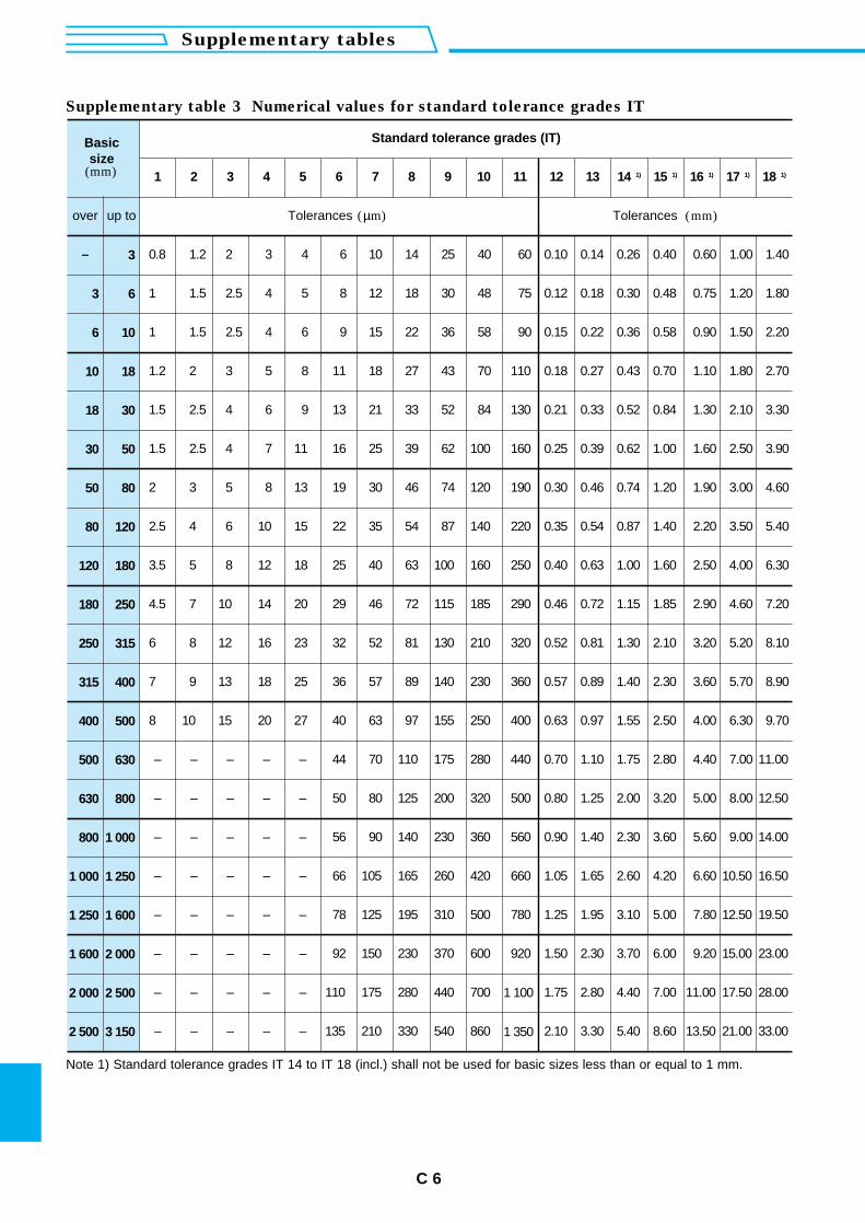
C 6
Supplementary tables
Basicsize
(mm)
Standard tolerance grades (IT)
1 2 3 4 5 6 7 8 9 10 11 12 13 14 1) 15 1) 16 1) 17 1) 18 1)
over up to Tolerances (µm) Tolerances (mm)
– 3 0.8 1.2 2 3 4 6 10 14 25 40 60 0.10 0.14 0.26 0.40 0.60 1.00 1.40
3 6 1 1.5 2.5 4 5 8 12 18 30 48 75 0.12 0.18 0.30 0.48 0.75 1.20 1.80
6 10 1 1.5 2.5 4 6 9 15 22 36 58 90 0.15 0.22 0.36 0.58 0.90 1.50 2.20
10 18 1.2 2 3 5 8 11 18 27 43 70 110 0.18 0.27 0.43 0.70 1.10 1.80 2.70
18 30 1.5 2.5 4 6 9 13 21 33 52 84 130 0.21 0.33 0.52 0.84 1.30 2.10 3.30
30 50 1.5 2.5 4 7 11 16 25 39 62 100 160 0.25 0.39 0.62 1.00 1.60 2.50 3.90
50 80 2 3 5 8 13 19 30 46 74 120 190 0.30 0.46 0.74 1.20 1.90 3.00 4.60
80 120 2.5 4 6 10 15 22 35 54 87 140 220 0.35 0.54 0.87 1.40 2.20 3.50 5.40
120 180 3.5 5 8 12 18 25 40 63 100 160 250 0.40 0.63 1.00 1.60 2.50 4.00 6.30
180 250 4.5 7 10 14 20 29 46 72 115 185 290 0.46 0.72 1.15 1.85 2.90 4.60 7.20
250 315 6 8 12 16 23 32 52 81 130 210 320 0.52 0.81 1.30 2.10 3.20 5.20 8.10
315 400 7 9 13 18 25 36 57 89 140 230 360 0.57 0.89 1.40 2.30 3.60 5.70 8.90
400 500 8 10 15 20 27 40 63 97 155 250 400 0.63 0.97 1.55 2.50 4.00 6.30 9.70
500 630 – – – – – 44 70 110 175 280 440 0.70 1.10 1.75 2.80 4.40 7.00 11.00
630 800 – – – – – 50 80 125 200 320 500 0.80 1.25 2.00 3.20 5.00 8.00 12.50
800 1 000 – – – – – 56 90 140 230 360 560 0.90 1.40 2.30 3.60 5.60 9.00 14.00
1 000 1 250 – – – – – 66 105 165 260 420 660 1.05 1.65 2.60 4.20 6.60 10.50 16.50
1 250 1 600 – – – – – 78 125 195 310 500 780 1.25 1.95 3.10 5.00 7.80 12.50 19.50
1 600 2 000 – – – – – 92 150 230 370 600 920 1.50 2.30 3.70 6.00 9.20 15.00 23.00
2 000 2 500 – – – – – 110 175 280 440 700 1 100 1.75 2.80 4.40 7.00 11.00 17.50 28.00
2 500 3 150 – – – – – 135 210 330 540 860 1 350 2.10 3.30 5.40 8.60 13.50 21.00 33.00
Supplementary table 3 Numerical values for standard tolerance grades IT
Note 1) Standard tolerance grades IT 14 to IT 18 (incl.) shall not be used for basic sizes less than or equal to 1 mm.
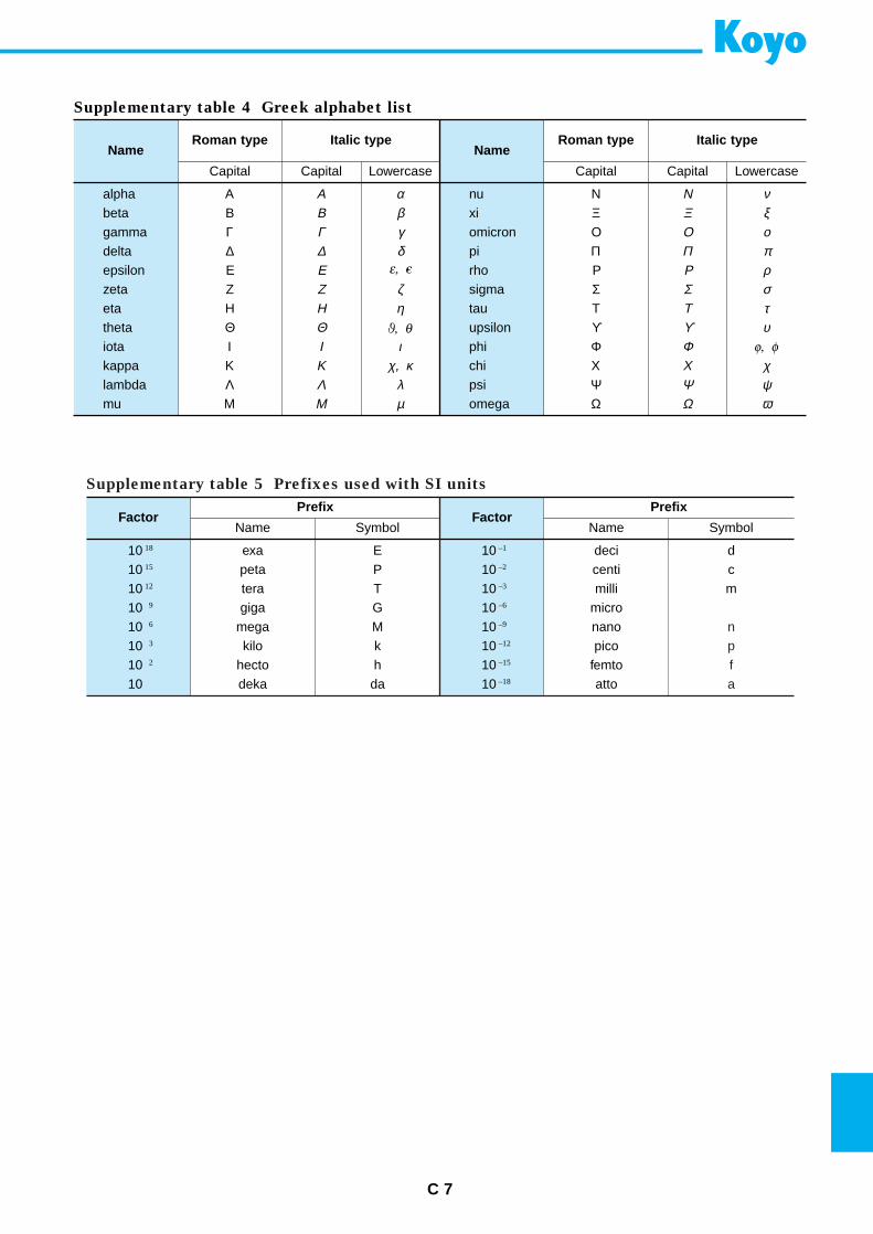
Factor
10 –1
10 –2
10 –3
10 –6
10 –9
10 –12
10 –15
10 –18
Name Name
alphabetagammadeltaepsilonzetaetathetaiotakappalambdamu
nuxiomicronpirhosigmatauupsilonphichipsiomega
C 7
Supplementary table 4 Greek alphabet list
Roman type
Capital
Italic type
Capital Lowercase
Roman type
Capital
Italic type
Capital Lowercase
ΑΒΓ∆ΕΖΗΘΙΚΛΜ
ΑΒΓ∆ΕΖΗΘΙΚΛΜ
αβγδ
ζη
ιχ, κ
λµ
ΝΞΟΠΡΣΤϒΦΧΨΩ
ΝΞΟΠΡΣΤϒΦΧΨΩ
νξοπρστυ
χψω
Factor
10 18
10 15
10 12
10 9
10 6
10 3
10 2
10
Prefix
Name Symbol
exapetateragiga
megakilo
hectodeka
EPTGMkhda
Prefix
Name Symbol
decicentimilli
micronanopico
femtoatto
dcm
npfa
Supplementary table 5 Prefixes used with SI units
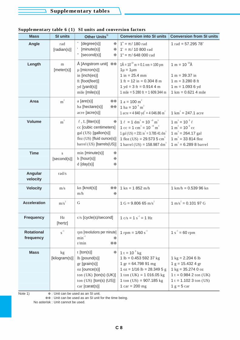
Note 1) : Unit can be used as an SI unit. : Unit can be used as an SI unit for the time being.
No asterisk : Unit cannot be used.
Mass SI units Other Units1) Conversion into SI units Conversion from SI units
Angle rad ˚ [degree(s)] 1˚ = π / 180 rad 1 rad = 57.295 78˚[radian(s)] ' [minute(s)] 1' = π / 10 800 rad
" [second(s)] 1" = π / 648 000 rad
Length m Å [Angstrom unit] 1Å = 10–10
m = 0.1 nm = 100 pm 1 m = 10 10
Å[meter(s)] µ [micron(s)] 1µ = 1µm
in [inch(es)] 1 in = 25.4 mm 1 m = 39.37 inft [foot(feet)] 1 ft = 12 in = 0.304 8 m 1 m = 3.280 8 ftyd [yard(s)] 1 yd = 3 ft = 0.914 4 m 1 m = 1.093 6 ydmile [mile(s)] 1 mile = 5 280 ft = 1 609.344 m 1 km = 0.621 4 mile
Area m2 a [are(s)] 1 a = 100 m
2
ha [hectare(s)] 1 ha = 10 4
m2
acre [acre(s)] 1 acre = 4 840 yd2= 4 046.86 m
21 km
2= 247.1 acre
Volume m3 r, L [liter(s)] 1r = 1 dm
3= 10
–3m
31 m
3= 10
3r
cc [cubic centimeters] 1 cc = 1 cm3= 10
–6m
31 m
3= 10
6cc
gal (US) [gallon(s)] 1 gal (US) = 231 in3= 3.785 41 dm
31 m
3= 264.17 gal
floz (US) [fluid ounce(s)] 1 floz (US) = 29.573 5 cm3
1 m3= 33 814 floz
barrel (US) [barrels(US)] 1 barrel (US) = 158.987 dm3
1 m3= 6.289 8 barrel
Time s min [minute(s)]
[second(s)] h [hour(s)]
d [day(s)]
Angular rad/svelocity
Velocity m/s kn [knot(s)] 1 kn = 1 852 m/h 1 km/h = 0.539 96 knm/h
Acceleration m/s2 G 1 G = 9.806 65 m/s
21 m/s
2= 0.101 97 G
Frequency Hz c/s [cycle(s)/second] 1 c/s = 1 s–1
= 1 Hz[hertz]
Rotational s–1 rpm [revolutions per minute] 1 rpm = 1/60 s
–11 s
–1= 60 rpm
frequency min–1
Mass kg t [ton(s)] 1 t = 10 3
kg [kilogram(s)] lb [pound(s)] 1 lb = 0.453 592 37 kg 1 kg = 2.204 6 lb
gr [grain(s)] 1 gr = 64.798 91 mg 1 g = 15.432 4 groz [ounce(s)] 1 oz = 1/16 lb = 28.349 5 g 1 kg = 35.274 0 ozton (UK) [ton(s) (UK)] 1 ton (UK) = 1 016.05 kg 1 t = 0.984 2 ton (UK)ton (US) [ton(s) (US)] 1 ton (US) = 907.185 kg 1 t = 1.102 3 ton (US)car [carat(s)] 1 car = 200 mg 1 g = 5 car
r/min
C 8
Supplementary tables
Supplementary table 6 (1) SI units and conversion factors
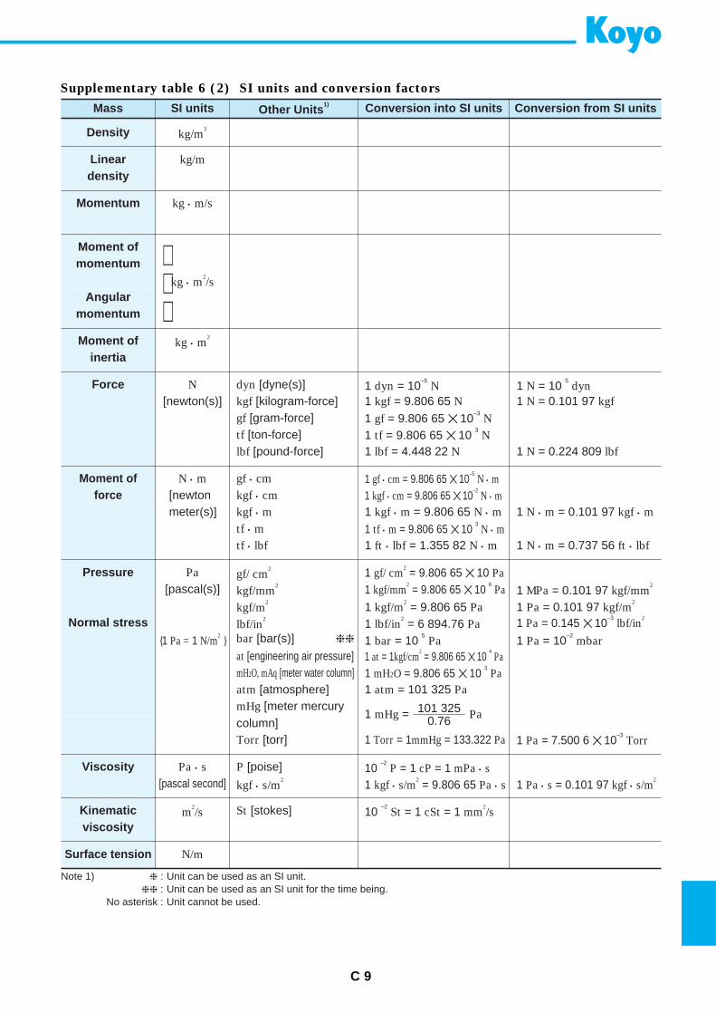
C 9
Note 1) : Unit can be used as an SI unit. : Unit can be used as an SI unit for the time being.
No asterisk : Unit cannot be used.
Mass SI units Other Units1) Conversion into SI units Conversion from SI units
Density kg/m3
Linear kg/mdensity
Momentum kg • m/s
Moment ofmomentum
kg • m2/s
Angularmomentum
Moment of kg • m2
inertia
Force N dyn [dyne(s)] 1 dyn = 10–5
N 1 N = 10 5
dyn[newton(s)] kgf [kilogram-force] 1 kgf = 9.806 65 N 1 N = 0.101 97 kgf
gf [gram-force] 1 gf = 9.806 65 10–3
Ntf [ton-force] 1 tf = 9.806 65 10
3N
lbf [pound-force] 1 lbf = 4.448 22 N 1 N = 0.224 809 lbf
Moment of N • m gf • cm 1 gf • cm = 9.806 65 10–5
N • mforce [newton kgf • cm 1 kgf • cm = 9.806 65 10
–2N • m
meter(s)] kgf • m 1 kgf • m = 9.806 65 N • m 1 N • m = 0.101 97 kgf • mtf • m 1 tf • m = 9.806 65 10
3N • m
tf • lbf 1 ft • lbf = 1.355 82 N • m 1 N • m = 0.737 56 ft • lbf
Pressure Pa gf/ cm2 1 gf/ cm
2= 9.806 65 10 Pa
[pascal(s)] kgf/mm2 1 kgf/mm
2= 9.806 65 10
6Pa 1 MPa = 0.101 97 kgf/mm
2
kgf/m2
1 kgf/m2= 9.806 65 Pa 1 Pa = 0.101 97 kgf/m
2
Normal stress lbf/in2
1 lbf/in2= 6 894.76 Pa 1 Pa = 0.145 10
–3lbf/in
2
1 Pa = 1 N/m2 bar [bar(s)] 1 bar = 10
5Pa 1 Pa = 10
–2mbar
at [engineering air pressure] 1 at = 1kgf/cm2= 9.806 65 10
4Pa
mH2O, mAq [meter water column] 1 mH2O = 9.806 65 10 3
Paatm [atmosphere] 1 atm = 101 325 PamHg [meter mercurycolumn]
1 mHg = Pa101 3250.76
Torr [torr] 1 Torr = 1mmHg = 133.322 Pa 1 Pa = 7.500 6 10–3
Torr
Viscosity Pa • s P [poise] 10 –2
P = 1 cP = 1 mPa • s[pascal second] kgf • s/m
21 kgf • s/m
2= 9.806 65 Pa • s 1 Pa • s = 0.101 97 kgf • s/m
2
Kinematic m2/s St [stokes] 10
–2St = 1 cSt = 1 mm
2/s
Surface tension N/m
viscosity
Supplementary table 6 (2) SI units and conversion factors
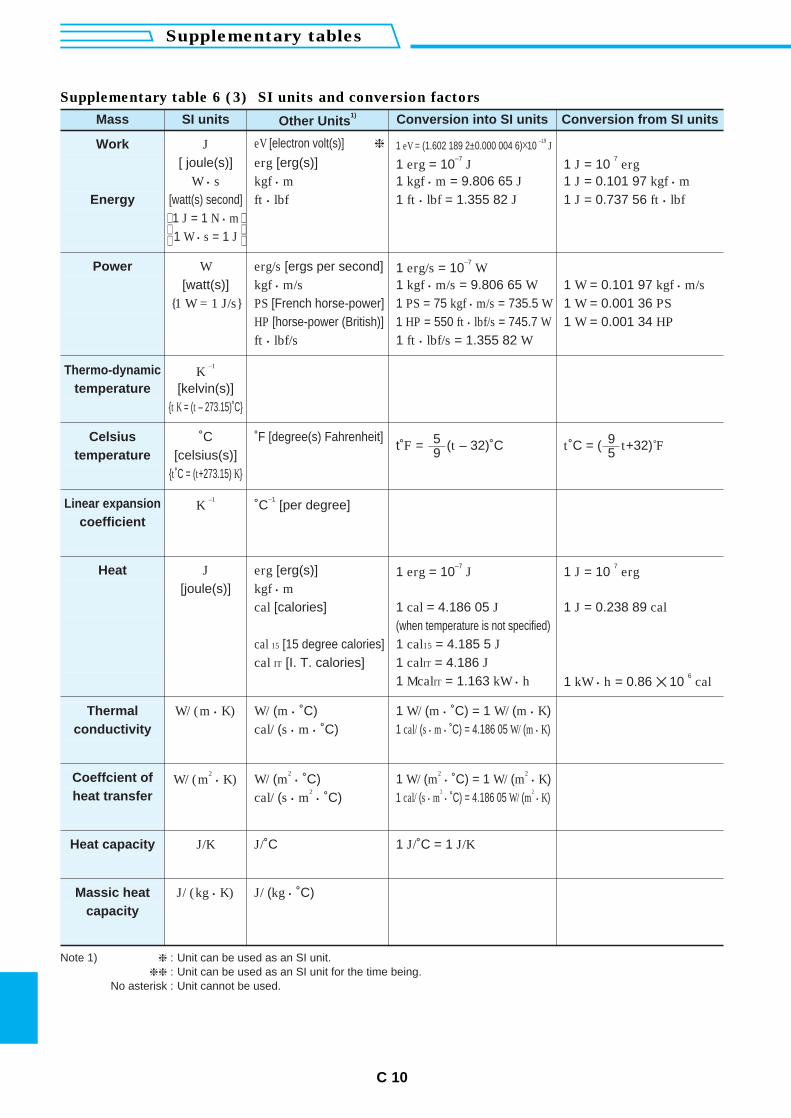
C 10
Supplementary tables
Mass SI units Other Units1) Conversion into SI units Conversion from SI units
Work J eV [electron volt(s)] 1 eV = (1.602 189 2±0.000 004 6)10 –19
J
[ joule(s)] erg [erg(s)] 1 erg = 10–7
J 1 J = 10 7
ergW • s kgf • m 1 kgf • m = 9.806 65 J 1 J = 0.101 97 kgf • m
Energy [watt(s) second] ft • lbf 1 ft • lbf = 1.355 82 J 1 J = 0.737 56 ft • lbf1 J = 1 N • m1 W • s = 1 J
Power W erg/s [ergs per second] 1 erg/s = 10–7
W[watt(s)] kgf • m/s 1 kgf • m/s = 9.806 65 W 1 W = 0.101 97 kgf • m/s
1 W = 1 J/s PS [French horse-power] 1 PS = 75 kgf • m/s = 735.5 W 1 W = 0.001 36 PSHP [horse-power (British)] 1 HP = 550 ft • lbf/s = 745.7 W 1 W = 0.001 34 HPft • lbf/s 1 ft • lbf/s = 1.355 82 W
Thermo-dynamic K –1
temperature [kelvin(s)]t K = (t – 273.15)˚C
Celsius ˚C ˚F [degree(s) Fahrenheit]t˚F = (t – 32)˚C5
9 t˚C = ( t+32)˚F95temperature [celsius(s)]
t˚C = (t+273.15) K
Linear expansion K –1
˚C–1
[per degree]coefficient
Heat J erg [erg(s)] 1 erg = 10–7
J 1 J = 10 7
erg[joule(s)] kgf • m
cal [calories] 1 cal = 4.186 05 J 1 J = 0.238 89 cal(when temperature is not specified)
cal 15 [15 degree calories] 1 cal15 = 4.185 5 Jcal IT [I. T. calories] 1 calIT = 4.186 J
1 McalIT = 1.163 kW • h 1 kW • h = 0.86 10 6
cal
Thermal W/ (m • K) W/ (m • ˚C) 1 W/ (m • ˚C) = 1 W/ (m • K)conductivity cal/ (s • m • ˚C) 1 cal/ (s • m • ˚C) = 4.186 05 W/ (m • K)
Coeffcient of W/ (m2
• K) W/ (m2
• ˚C) 1 W/ (m2
• ˚C) = 1 W/ (m2
• K)heat transfer cal/ (s • m
2• ˚C) 1 cal/ (s • m
2• ˚C) = 4.186 05 W/ (m
2• K)
Heat capacity J/K J/˚C 1 J/˚C = 1 J/K
Massic heat J/ (kg • K) J/ (kg • ˚C)capacity
Note 1) : Unit can be used as an SI unit. : Unit can be used as an SI unit for the time being.
No asterisk : Unit cannot be used.
Supplementary table 6 (3) SI units and conversion factors
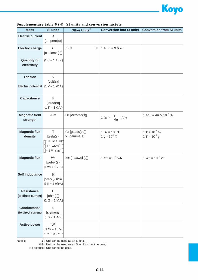
C 11
Mass SI units Other Units1) Conversion into SI units Conversion from SI units
Electric current A[ampere(s)]
Electric charge C A • h 1 A • h = 3.6 kC[coulomb(s)]
Quantity of 1 C = 1 A • selectricity
Tension V[volt(s)]
Electric potential 1 V = 1 W/A
Capacitance F[farad(s)]
1 F = 1 C/V
Magnetic field A/m Oe [oersted(s)]1 Oe = A/m10
3
4π1 A/m = 4π 10
–3Oe
strength
Magnetic flux T Gs [gauss(es)] 1 Gs = 10–4
T 1 T = 10 4
Gsdensity [tesla(s)] γ [ gamma(s)] 1 γ = 10
–9T 1 T = 10
9 γ1 T = 1 N/(A • m)
= 1 Wb/m2
= 1 V • s/m2
Magnetic flux Wb Mx [maxwell(s)] 1 Mx =10–8
Wb 1 Wb = 10 8
Mx[weber(s)]
1 Wb = 1 V • s
Self inductance H[henry (– ries)]1 H = 1 Wb/A
Resistance Ω(to direct current) [ohm(s)]
1 Ω = 1 V/A
Conductance S(to direct current) [siemens]
1 S = 1 A/V
Active power W1 W = 1 J/s
= 1 A • V
Note 1) : Unit can be used as an SI unit. : Unit can be used as an SI unit for the time being.
No asterisk : Unit cannot be used.
Supplementary table 6 (4) SI units and conversion factors
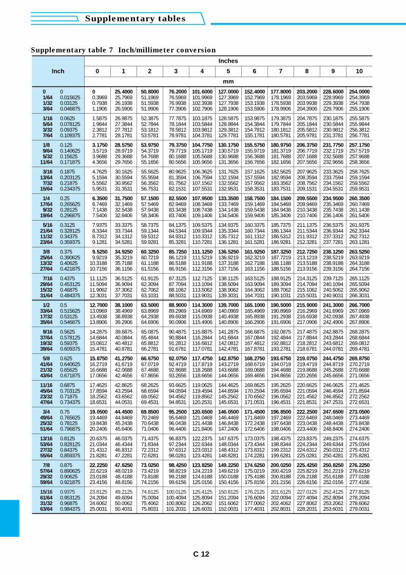
C 12
Supplementary tables
Inch
Inches
0 1 2 3 4 5 6 7 8 9
mm
15/16 0.9375 23.8125 49.2125 74.6125 100.0125 125.4125 150.8125 176.2125 201.6125 227.0125 252.412561/64 0.953125 24.2094 49.6094 75.0094 100.4094 125.8094 151.2094 176.6094 202.0094 227.4094 252.809431/32 0.96875 24.6062 50.0062 75.4062 100.8062 126.2062 151.6062 177.0062 202.4062 227.8062 253.206263/64 0.984375 25.0031 50.4031 75.8031 101.2031 126.6031 152.0031 177.4031 202.8031 228.2031 253.6031
10
277.8125278.2094278.6062279.0031
0 0 0 25.4000 50.8000 76.2000 101.6000 127.0000 152.4000 177.8000 203.2000 228.6000 254.00001/64 0.015625 0.3969 25.7969 51.1969 76.5969 101.9969 127.3969 152.7969 178.1969 203.5969 228.9969 254.39691/32 0.03125 0.7938 26.1938 51.5938 76.9938 102.3938 127.7938 153.1938 178.5938 203.9938 229.3938 254.79383/64 0.046875 1.1906 26.5906 51.9906 77.3906 102.7906 128.1906 153.5906 178.9906 204.3906 229.7906 255.1906
1/16 0.0625 1.5875 26.9875 52.3875 77.7875 103.1875 128.5875 153.9875 179.3875 204.7875 230.1875 255.58755/64 0.078125 1.9844 27.3844 52.7844 78.1844 103.5844 128.9844 154.3844 179.7844 205.1844 230.5844 255.98443/32 0.09375 2.3812 27.7812 53.1812 78.5812 103.9812 129.3812 154.7812 180.1812 205.5812 230.9812 256.38127/64 0.109375 2.7781 28.1781 53.5781 78.9781 104.3781 129.7781 155.1781 180.5781 205.9781 231.3781 256.7781
1/8 0.125 3.1750 28.5750 53.9750 79.3750 104.7750 130.1750 155.5750 180.9750 206.3750 231.7750 257.17509/64 0.140625 3.5719 28.9719 54.3719 79.7719 105.1719 130.5719 155.9719 181.3719 206.7719 232.1719 257.57195/32 0.15625 3.9688 29.3688 54.7688 80.1688 105.5688 130.9688 156.3688 181.7688 207.1688 232.5688 257.9688
11/64 0.171875 4.3656 29.7656 55.1656 80.5656 105.9656 131.3656 156.7656 182.1656 207.5656 232.9656 258.3656
3/16 0.1875 4.7625 30.1625 55.5625 80.9625 106.3625 131.7625 157.1625 182.5625 207.9625 233.3625 258.762513/64 0.203125 5.1594 30.5594 55.9594 81.3594 106.7594 132.1594 157.5594 182.9594 208.3594 233.7594 259.1594
7/32 0.21875 5.5562 30.9562 56.3562 81.7562 107.1562 132.5562 157.9562 183.3562 208.7562 234.1562 259.556215/64 0.234375 5.9531 31.3531 56.7531 82.1531 107.5531 132.9531 158.3531 183.7531 209.1531 234.5531 259.9531
1/4 0.25 6.3500 31.7500 57.1500 82.5500 107.9500 133.3500 158.7500 184.1500 209.5500 234.9500 260.350017/64 0.265625 6.7469 32.1469 57.5469 82.9469 108.3469 133.7469 159.1469 184.5469 209.9469 235.3469 260.7469
9/32 0.28125 7.1438 32.5438 57.9438 83.3438 108.7438 134.1438 159.5438 184.9438 210.3438 235.7438 261.143819/64 0.296875 7.5406 32.9406 58.3406 83.7406 109.1406 134.5406 159.9406 185.3406 210.7406 236.1406 261.5406
5/16 0.3125 7.9375 33.3375 58.7375 84.1375 109.5375 134.9375 160.3375 185.7375 211.1375 236.5375 261.937521/64 0.328125 8.3344 33.7344 59.1344 84.5344 109.9344 135.3344 160.7344 186.1344 211.5344 236.9344 262.334411/32 0.34375 8.7312 34.1312 59.5312 84.9312 110.3312 135.7312 161.1312 186.5312 211.9312 237.3312 262.731223/64 0.359375 9.1281 34.5281 59.9281 85.3281 110.7281 136.1281 161.5281 186.9281 212.3281 237.7281 263.1281
3/8 0.375 9.5250 34.9250 60.3250 85.7250 111.1250 136.5250 161.9250 187.3250 212.7250 238.1250 263.525025/64 0.390625 9.9219 35.3219 60.7219 86.1219 111.5219 136.9219 162.3219 187.7219 213.1219 238.5219 263.921913/32 0.40625 10.3188 35.7188 61.1188 86.5188 111.9188 137.3188 162.7188 188.1188 213.5188 238.9188 264.318827/64 0.421875 10.7156 36.1156 61.5156 86.9156 112.3156 137.7156 163.1156 188.5156 213.9156 239.3156 264.7156
7/16 0.4375 11.1125 36.5125 61.9125 87.3125 112.7125 138.1125 163.5125 188.9125 214.3125 239.7125 265.112529/64 0.453125 11.5094 36.9094 62.3094 87.7094 113.1094 138.5094 163.9094 189.3094 214.7094 240.1094 265.509415/32 0.46875 11.9062 37.3062 62.7062 88.1062 113.5062 138.9062 164.3062 189.7062 215.1062 240.5062 265.906231/64 0.484375 12.3031 37.7031 63.1031 88.5031 113.9031 139.3031 164.7031 190.1031 215.5031 240.9031 266.3031
1/2 0.5 12.7000 38.1000 63.5000 88.9000 114.3000 139.7000 165.1000 190.5000 215.9000 241.3000 266.700033/64 0.515625 13.0969 38.4969 63.8969 89.2969 114.6969 140.0969 165.4969 190.8969 216.2969 241.6969 267.096917/32 0.53125 13.4938 38.8938 64.2938 89.6938 115.0938 140.4938 165.8938 191.2938 216.6938 242.0938 267.493835/64 0.546875 13.8906 39.2906 64.6906 90.0906 115.4906 140.8906 166.2906 191.6906 217.0906 242.4906 267.8906
9/16 0.5625 14.2875 39.6875 65.0875 90.4875 115.8875 141.2875 166.6875 192.0875 217.4875 242.8875 268.287537/64 0.578125 14.6844 40.0844 65.4844 90.8844 116.2844 141.6844 167.0844 192.4844 217.8844 243.2844 268.684419/32 0.59375 15.0812 40.4812 65.8812 91.2812 116.6812 142.0812 167.4812 192.8812 218.2812 243.6812 269.081239/64 0.609375 15.4781 40.8781 66.2781 91.6781 117.0781 142.4781 167.8781 193.2781 218.6781 244.0781 269.4781
5/8 0.625 15.8750 41.2750 66.6750 92.0750 117.4750 142.8750 168.2750 193.6750 219.0750 244.4750 269.875041/64 0.640625 16.2719 41.6719 67.0719 92.4719 117.8719 143.2719 168.6719 194.0719 219.4719 244.8719 270.271921/32 0.65625 16.6688 42.0688 67.4688 92.8688 118.2688 143.6688 169.0688 194.4688 219.8688 245.2688 270.668843/64 0.671875 17.0656 42.4656 67.8656 93.2656 118.6656 144.0656 169.4656 194.8656 220.2656 245.6656 271.0656
11/16 0.6875 17.4625 42.8625 68.2625 93.6625 119.0625 144.4625 169.8625 195.2625 220.6625 246.0625 271.462545/64 0.703125 17.8594 43.2594 68.6594 94.0594 119.4594 144.8594 170.2594 195.6594 221.0594 246.4594 271.859423/32 0.71875 18.2562 43.6562 69.0562 94.4562 119.8562 145.2562 170.6562 196.0562 221.4562 246.8562 272.256247/64 0.734375 18.6531 44.0531 69.4531 94.8531 120.2531 145.6531 171.0531 196.4531 221.8531 247.2531 272.6531
3/4 0.75 19.0500 44.4500 69.8500 95.2500 120.6500 146.0500 171.4500 196.8500 222.2500 247.6500 273.050049/64 0.765625 19.4469 44.8469 70.2469 95.6469 121.0469 146.4469 171.8469 197.2469 222.6469 248.0469 273.446925/32 0.78125 19.8438 45.2438 70.6438 96.0438 121.4438 146.8438 172.2438 197.6438 223.0438 248.4438 273.843851/64 0.796875 20.2406 45.6406 71.0406 96.4406 121.8406 147.2406 172.6406 198.0406 223.4406 248.8406 274.2406
13/16 0.8125 20.6375 46.0375 71.4375 96.8375 122.2375 147.6375 173.0375 198.4375 223.8375 249.2375 274.637553/64 0.828125 21.0344 46.4344 71.8344 97.2344 122.6344 148.0344 173.4344 198.8344 224.2344 249.6344 275.034427/32 0.84375 21.4312 46.8312 72.2312 97.6312 123.0312 148.4312 173.8312 199.2312 224.6312 250.0312 275.431255/64 0.859375 21.8281 47.2281 72.6281 98.0281 123.4281 148.8281 174.2281 199.6281 225.0281 250.4281 275.8281
7/8 0.875 22.2250 47.6250 73.0250 98.4250 123.8250 149.2250 174.6250 200.0250 225.4250 250.8250 276.225057/64 0.890625 22.6219 48.0219 73.4219 98.8219 124.2219 149.6219 175.0219 200.4219 225.8219 251.2219 276.621929/32 0.90625 23.0188 48.4188 73.8188 99.2188 124.6188 150.0188 175.4188 200.8188 226.2188 251.6188 277.018859/64 0.921875 23.4156 48.8156 74.2156 99.6156 125.0156 150.4156 175.8156 201.2156 226.6156 252.0156 277.4156
Supplementary table 7 Inch/millimeter conversion
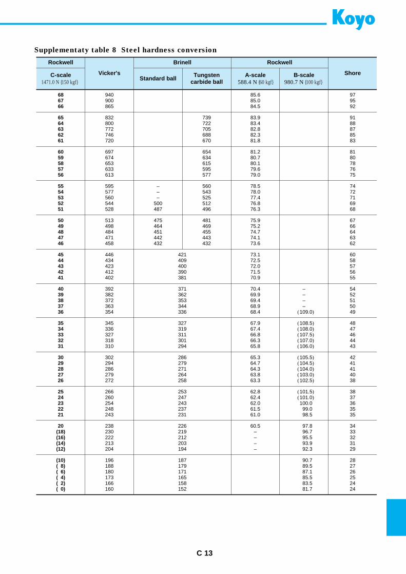
C 13
Rockwell
Vicker's
Brinell Rockwell
ShoreC-scale1471.0 N 150 kgf
Standard ball Tungsten carbide ball
A-scale588.4 N 60 kgf
B-scale980.7 N 100 kgf
68 940 85.6 9767 900 85.0 9566 865 84.5 92
65 832 739 83.9 9164 800 722 83.4 8863 772 705 82.8 8762 746 688 82.3 8561 720 670 81.8 83
60 697 654 81.2 8159 674 634 80.7 8058 653 615 80.1 7857 633 595 79.6 7656 613 577 79.0 75
55 595 – 560 78.5 7454 577 – 543 78.0 7253 560 – 525 77.4 7152 544 500 512 76.8 6951 528 487 496 76.3 68
50 513 475 481 75.9 6749 498 464 469 75.2 6648 484 451 455 74.7 6447 471 442 443 74.1 6346 458 432 432 73.6 62
45 446 421 73.1 6044 434 409 72.5 5843 423 400 72.0 5742 412 390 71.5 5641 402 381 70.9 55
40 392 371 70.4 – 5439 382 362 69.9 – 5238 372 353 69.4 – 5137 363 344 68.9 – 5036 354 336 68.4 (109.0) 49
35 345 327 67.9 (108.5) 4834 336 319 67.4 (108.0) 4733 327 311 66.8 (107.5) 4632 318 301 66.3 (107.0) 4431 310 294 65.8 (106.0) 43
30 302 286 65.3 (105.5) 4229 294 279 64.7 (104.5) 4128 286 271 64.3 (104.0) 4127 279 264 63.8 (103.0) 4026 272 258 63.3 (102.5) 38
25 266 253 62.8 (101.5) 3824 260 247 62.4 (101.0) 3723 254 243 62.0 100.0 3622 248 237 61.5 99.0 3521 243 231 61.0 98.5 35
20 238 226 60.5 97.8 34(18) 230 219 – 96.7 33(16) 222 212 – 95.5 32(14) 213 203 – 93.9 31(12) 204 194 – 92.3 29
(10) 196 187 90.7 28( 8) 188 179 89.5 27( 6) 180 171 87.1 26( 4) 173 165 85.5 25( 2) 166 158 83.5 24( 0) 160 152 81.7 24
Supplementaty table 8 Steel hardness conversion
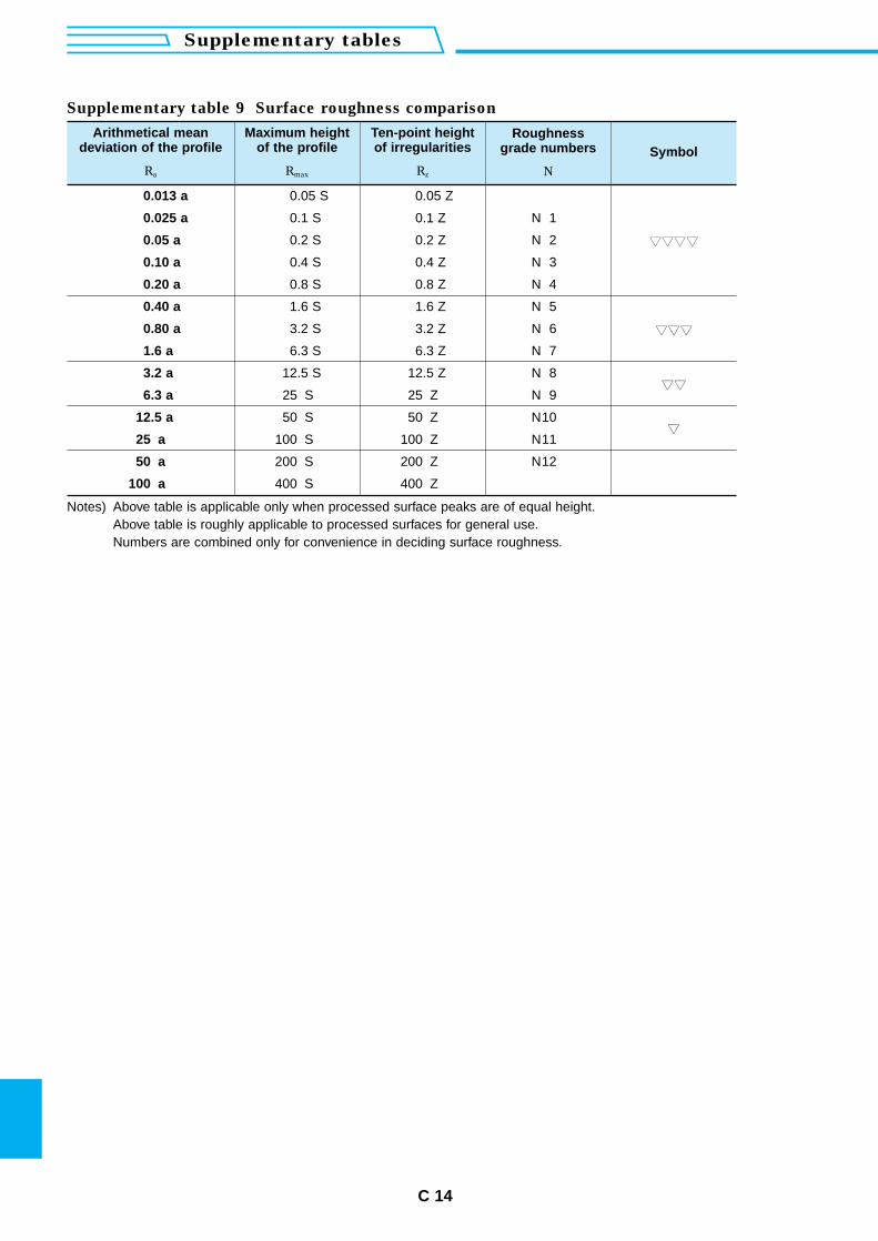
C 14
Supplementary tables
Supplementary table 9 Surface roughness comparison
Arithmetical meandeviation of the profile
Ra
Maximum height of the profile
Rmax
Ten-point heightof irregularities
Rz
Roughnessgrade numbers
N
Symbol
0.013 a
0.025 a
0.05 a
0.10 a
0.20 a
0.40 a
0.80 a
1.6 a
3.2 a
6.3 a
12.5 a
25. a
50. a
100. a
N 1
N 2
N 3
N 4
N 5
N 6
N 7
N 8
N 9
N10
N11
N12
0.05 S
0.1 S
0.2 S
0.4 S
0.8 S
1.6 S
3.2 S
6.3 S
12.5 S
25. S
50. S
100. S
200. S
400. S
0.05 Z
0.1 Z
0.2 Z
0.4 Z
0.8 Z
1.6 Z
3.2 Z
6.3 Z
12.5 Z
25. Z
50. Z
100. Z
200. Z
400. Z
Notes) Above table is applicable only when processed surface peaks are of equal height.Above table is roughly applicable to processed surfaces for general use.Numbers are combined only for convenience in deciding surface roughness.
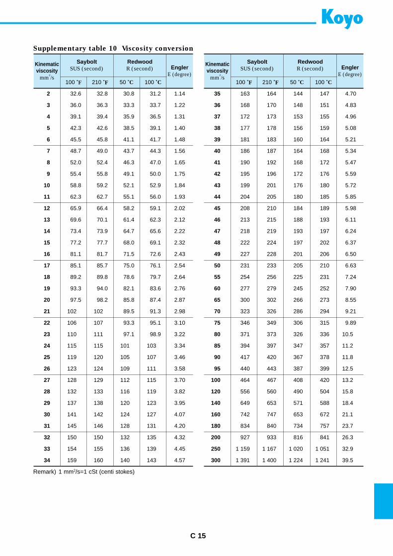
C 15
Kinematicviscosity
mm2/s
SayboltSUS (second)
RedwoodR (second) Engler
E (degree)
100 ˚F 210 ˚F 50 ˚C 100 ˚C
2 32.6 32.8 30.8 31.2 1.14
3 36.0 36.3 33.3 33.7 1.22
4 39.1 39.4 35.9 36.5 1.31
5 42.3 42.6 38.5 39.1 1.40
6 45.5 45.8 41.1 41.7 1.48
7 48.7 49.0 43.7 44.3 1.56
8 52.0 52.4 46.3 47.0 1.65
9 55.4 55.8 49.1 50.0 1.75
10 58.8 59.2 52.1 52.9 1.84
11 62.3 62.7 55.1 56.0 1.93
12 65.9 66.4 58.2 59.1 2.02
13 69.6 70.1 61.4 62.3 2.12
14 73.4 73.9 64.7 65.6 2.22
15 77.2 77.7 68.0 69.1 2.32
16 81.1 81.7 71.5 72.6 2.43
17 85.1 85.7 75.0 76.1 2.54
18 89.2 89.8 78.6 79.7 2.64
19 93.3 94.0 82.1 83.6 2.76
20 97.5 98.2 85.8 87.4 2.87
21 102 102 89.5 91.3 2.98
22 106 107 93.3 95.1 3.10
23 110 111 97.1 98.9 3.22
24 115 115 101 103 3.34
25 119 120 105 107 3.46
26 123 124 109 111 3.58
27 128 129 112 115 3.70
28 132 133 116 119 3.82
29 137 138 120 123 3.95
30 141 142 124 127 4.07
31 145 146 128 131 4.20
32 150 150 132 135 4.32
33 154 155 136 139 4.45
34 159 160 140 143 4.57
Kinematicviscosity
mm2/s
SayboltSUS (second)
RedwoodR (second) Engler
E (degree)
100 ˚F 210 ˚F 50 ˚C 100 ˚C
35 163 164 144 147 4.70
36 168 170 148 151 4.83
37 172 173 153 155 4.96
38 177 178 156 159 5.08
39 181 183 160 164 5.21
40 186 187 164 168 5.34
41 190 192 168 172 5.47
42 195 196 172 176 5.59
43 199 201 176 180 5.72
44 204 205 180 185 5.85
45 208 210 184 189 5.98
46 213 215 188 193 6.11
47 218 219 193 197 6.24
48 222 224 197 202 6.37
49 227 228 201 206 6.50
50 231 233 205 210 6.63
55 254 256 225 231 7.24
60 277 279 245 252 7.90
65 300 302 266 273 8.55
70 323 326 286 294 9.21
75 346 349 306 315 9.89
80 371 373 326 336 10.5
85 394 397 347 357 11.2
90 417 420 367 378 11.8
95 440 443 387 399 12.5
100 464 467 408 420 13.2
120 556 560 490 504 15.8
140 649 653 571 588 18.4
160 742 747 653 672 21.1
180 834 840 734 757 23.7
200 927 933 816 841 26.3
250 1 159 1 167 1 020 1 051 32.9
300 1 391 1 400 1 224 1 241 39.5
Supplementary table 10 Viscosity conversion
Remark) 1 mm2/s=1 cSt (centi stokes)
D 1
products information
Contents
Bearings and equipment
For automobiles ................................................................................... D 2
For motorcycles ................................................................................... D 4
For metal production equipment ....................................................... D 4
For railway rolling stock ..................................................................... D 5
For industrial machinery ..................................................................... D 5
For extreme special environment (EXSEV bearing series) ............. D 6
For space and aircraft ......................................................................... D 7
For office automation equipment and electric home appliances ... D 7
For other machinery ............................................................................ D 8
High precision machine components and apparatus ............................. D 9
Control type magnetic bearing spindles .................................................. D 9
Drive shafts .................................................................................................. D10
Propeller shafts ........................................................................................... D10
Constant velocity joints ............................................................................. D10
Oil seals, o-rings and resin parts .............................................................. D10
Factory automation systems and high precision machine tools ........... D11
Heat technology equipment ....................................................................... D11
Electronic parts ........................................................................................... D11
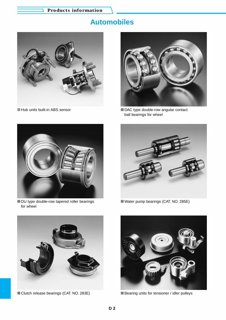
D 2
Products information
Automobiles
Hub units built-in ABS sensor DAC type double-row angular contactball bearings for wheel
DU type double-row tapered roller bearingsfor wheel
Water pump bearings (CAT. NO. 285E)
Clutch release bearings (CAT. NO. 283E) Bearing units for tensioner / idler pulleys
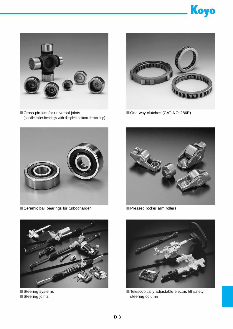
D 3
Cross pin kits for universal joints(needle roller bearings with dimpled bottom drawn cup)
One-way clutches (CAT. NO. 286E)
Ceramic ball bearings for turbocharger Pressed rocker arm rollers
Steering systems Steering joints
Telescopically adjustable electric tilt safetysteering column
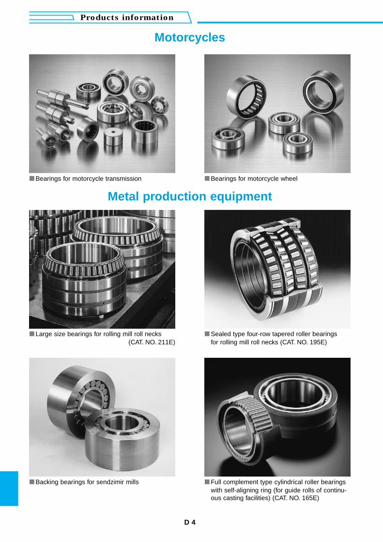
D 4
Products information
Bearings for motorcycle transmission Bearings for motorcycle wheel
Large size bearings for rolling mill roll necks(CAT. NO. 211E)
Sealed type four-row tapered roller bearingsfor rolling mill roll necks (CAT. NO. 195E)
Backing bearings for sendzimir mills Full complement type cylindrical roller bearingswith self-aligning ring (for guide rolls of continu-ous casting facilities) (CAT. NO. 165E)
Motorcycles
Metal production equipment
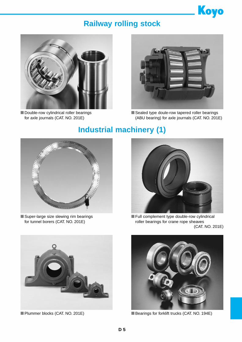
D 5
Double-row cylindrical roller bearingsfor axle journals (CAT. NO. 201E)
Sealed type doule-row tapered roller bearings(ABU bearing) for axle journals (CAT. NO. 201E)
Super-large size slewing rim bearingsfor tunnel borers (CAT. NO. 201E)
Full complement type double-row cylindricalroller bearings for crane rope sheaves
(CAT. NO. 201E)
Plummer blocks (CAT. NO. 201E) Bearings for forklift trucks (CAT. NO. 194E)
Industrial machinery (1)
Railway rolling stock
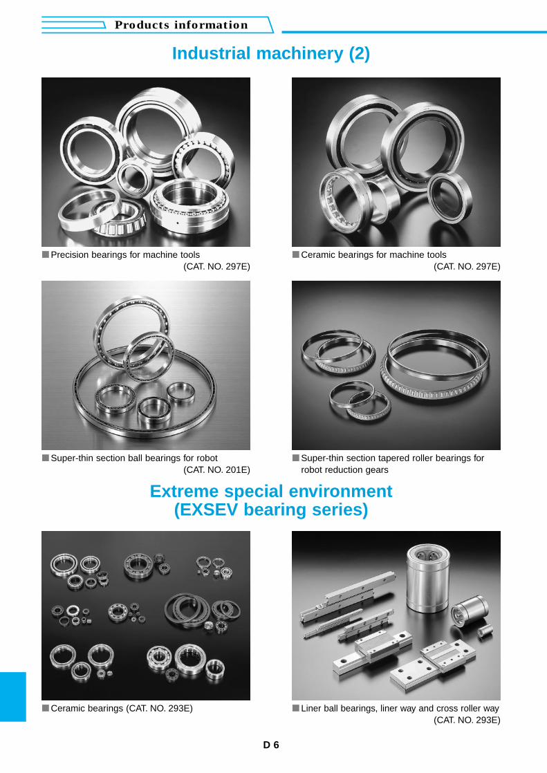
D 6
Products information
Precision bearings for machine tools(CAT. NO. 297E)
Ceramic bearings for machine tools(CAT. NO. 297E)
Super-thin section ball bearings for robot(CAT. NO. 201E)
Super-thin section tapered roller bearings forrobot reduction gears
Ceramic bearings (CAT. NO. 293E) Liner ball bearings, liner way and cross roller way(CAT. NO. 293E)
Extreme special environment(EXSEV bearing series)
Industrial machinery (2)
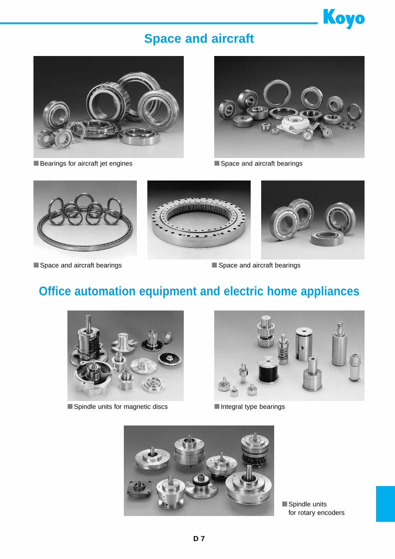
D 7
Bearings for aircraft jet engines
Space and aircraft bearings
Spindle units for magnetic discs Integral type bearings
Spindle unitsfor rotary encoders
Space and aircraft bearings
Space and aircraft bearings
Space and aircraft
Office automation equipment and electric home appliances

D 8
Products information
Other machinery
Needle roller bearings (CAT. NO. 201E) Cage and rollers (CAT. NO. 201E)
Extra-small & miniature ball bearings(CAT. NO. 295E)
Extra-small & miniature ball bearings with pulleies
Miniature one-way clutchesand one-way clutch units (CAT. NO. 113E)
Track rollers (CAT. NO. 201E)
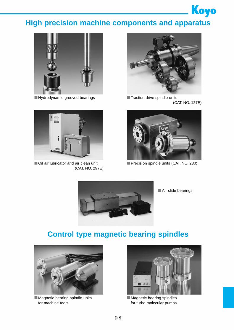
D 9
High precision machine components and apparatus
Control type magnetic bearing spindles
Hydrodynamic grooved bearings Traction drive spindle units(CAT. NO. 127E)
Oil air lubricator and air clean unit(CAT. NO. 297E)
Precision spindle units (CAT. NO. 280)
Magnetic bearing spindle unitsfor machine tools
Magnetic bearing spindlesfor turbo molecular pumps
Air slide bearings
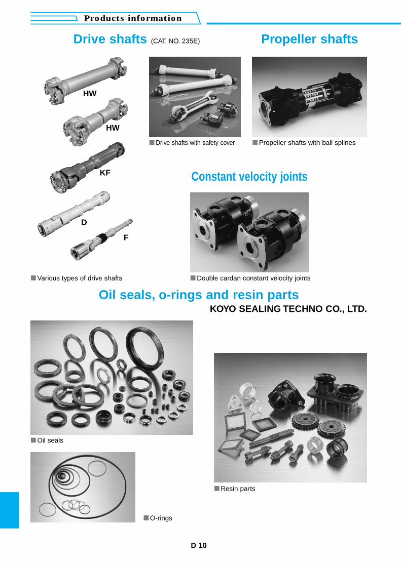
D 10
Products information
HW
HW
F
Drive shafts with safety cover Propeller shafts with ball splines
Various types of drive shafts Double cardan constant velocity joints
Drive shafts (CAT. NO. 235E) Propeller shafts
Oil seals, o-rings and resin partsKOYO SEALING TECHNO CO., LTD.
Constant velocity joints
Oil seals
Resin parts
O-rings
KF
D
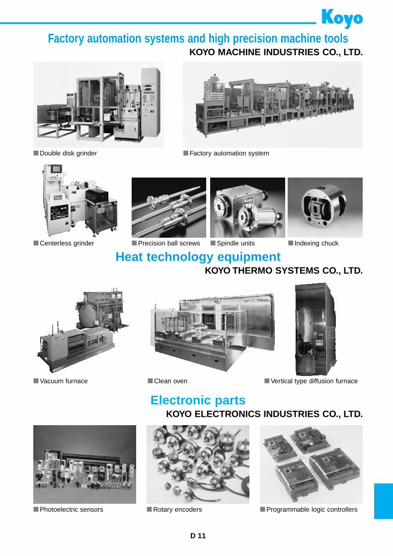
D 11
Vacuum furnace Vertical type diffusion furnace Clean oven
Factory automation systems and high precision machine toolsKOYO MACHINE INDUSTRIES CO., LTD.
Heat technology equipmentKOYO THERMO SYSTEMS CO., LTD.
Electronic partsKOYO ELECTRONICS INDUSTRIES CO., LTD.
Double disk grinder Factory automation system
Centerless grinder Indexing chuck Spindle units Precision ball screws
Photoelectric sensors Rotary encoders Programmable logic controllers
INTERNATIONAL NETWORK
KOYO SEIKO CO., LTD. HEAD OFFICENo.5-8, Minamisemba 3-chome, Chuo-ku, Osaka 542-8502, JAPANTEL : 81-6-6245-6087FAX : 81-6-6244-0814TLX : 63040 (KOYO OSJ)
KOYO CANADA INC.5324 South Service Road, Burlington, Ontario L7L 5H5, CANADATEL : 1-905-681-1121FAX : 1-905-681-1392
KOYO CORPORATION OF U.S.A.29570 Clemens Road, P.O.Box 45028 Westlake,OH 44145, U.S.A.TEL : 1-440-835-1000FAX : 1-440-835-9347TLX : 0985461(AMKOY RKVR)
KOYO CORPORATION OF U.S.A.47771 Halyard Drive, Plymouth, MI 48170, U.S.A.TEL : 1-734-454-1500FAX : 1-734-454-4076
KOYO STEERING SYSTEMS OF U.S.A. INC.47771 Halyard Drive, Plymouth, MI 48170, U.S.A.TEL : 1-734-454-7067FAX : 1-734-454-7059
KOYO DE MÉXICO, S.A.Av.Primero de Mayo No.153, 53500 NaucalpanEdo.de México, MÉXICOTEL : 52-5-358-0214/0077FAX : 52-5-576-8827/8871
KOYO LATIN AMERICA, S.A.P.O.Box 6-1797, El Dorado, Panama, REPUBLICA DE PANAMATEL : 507-264-0921/0977FAX : 507-264-2782/507-269-7578
KOYO ROLAMENTOS DO BRASIL LTDA.Rua Desembargador Eliseu Ghilherme 304, 7-Andar,Paraiso CEP 04004-30, BRASILTEL : 55-11-3887-9173FAX : 55-11-3887-3039
THAI KOYO CO., LTD.193/53 Lake Rajada Office Complex, 14th Floor Unit B,Rachadapisek Road, Klongtoey, Bangkok 10110, THAILANDTEL : 66-2-264-0395/661-9603~9605 FAX : 66-2-661-9606
KOYO SINGAPORE BEARING (PTE.) LTD.38 Tuas West Road, Singapore 638385, SINGAPORETEL : 65-274-2200FAX : 65-862-1623
PHILIPPINE KOYO BEARING CORPORATIONRm.504, Comfoods Bldg., Cor.Gil Puyat Ave. andPasong Tamo, Makati City, PHILIPPINESTEL : 63-2-817-8881/8901FAX : 63-2-867-3148
KOYO SEIKO CO., LTD. SEOUL BRANCHInwoo Building 6F, 539-11, Shinsa-Dong,Kangnam-Ku, Seoul, KOREATEL : 82-2-549-7922FAX : 82-2-549-7923
KOYO SEIKO CO., LTD. BEIJING LIAISON OFFICERoom 809, Jingtai Tower, 24 Jianguomenwai Street, Beijing,China, 100022TEL : 86-10-6515-0037FAX : 86-10-6515-0522
KOYO SEIKO CO.,LTD. SHANGHAI LIAISON OFFICERm.402, Aetna Tower, 107 Zunyi Road, Shanghai 200051, CHINATEL : 86-21-6237-5280FAX : 86-21-6237-5277
KOYO AUSTRALIA PTY. LTD.P.O.Box 442, Rydalmere, 2116 N.S.W., AUSTRALIATEL : 61-2-9638-2355FAX : 61-2-9638-3368
KOYO SEIKO CO., LTD. EUROPEAN CENTRAL OFFICEMarkerkant 13-01, 1314 AL Almere, THE NETHERLANDSTEL : 31-36-5383333FAX : 31-36-5347212
KOYO KULLAGER SCANDINAVIA A.B.Kanalvagen 1B, 194 61 Upplands-Vasby, SWEDENTEL : 46-8-594-212-00FAX : 46-8-594-212-29
KOYO STEERING EUROPE S.A.S.Zone Industrielle du Broteau, B.P.1, 69540 Irigny, FRANCETEL : 33-472-39-4444FAX : 33-472-39-2188
KOYO (U.K.) LTD.Whitehall Avenue, Kingston, Milton Keynes MK10 OAX,UNITED KINGDOMTEL : 44-1908-289300FAX : 44-1908-289333
EUROPA-KOYO B.V.P.O.Box 1-2965 ZG, Nieuwpoort, THE NETHERLANDSTEL : 31-184-606800FAX : 31-184-602572/606857
KOYO ROMANIA REPRESENTATIVE OFFICEStr. Frederic Jolliot-Curie, Nr.3, Etaj 1, Ap.2, Sector 5Bucharest, RUMANIATEL : 40-1-410-4170/4182/0984FAX : 40-1-410-1178
KOYO DEUTSCHLAND GMBH.P.O.Box 73 06 60, D-22126 Hamburg, GERMANYTEL : 49-40-67-9090-0FAX : 49-40-67-9203-0TLX : 213138(KOYO D)
KOYO FRANCE S.A.8 Rue Guy Moquet, B.P.189 Z.I., 95105 Argenteuil Cedex, FRANCETEL : 33-1-3998-4222FAX : 33-1-3998-4244/4249
KOYO IBERICA, S.A.Calle Belfast 15 Naves A y B, Poligono Ind. “Las Mercedes”,28022 Madrid, SPAINTEL : 34-91-329-0818FAX : 34-91-747-1194
KOYO ITALIA S.R.L.Via Bronzino 9, 20133 Milano, ITALYTEL : 39-02-2951-0844FAX : 39-02-2951-0954
OFFICES
( )
KOYO CORPORATION OF U.S.A.(MANUFACTURING DIVISION)
– Orangeburg Plant –P.O. Drawer 967, Highway 601 North, Orangeburg, SC 29115, U.S.A.TEL : 1-803-536-6200FAX : 1-803-534-0599
– Richland Plant –1006 Northpoint Blvd. Blythewood, SC 29016, U.S.A.TEL : 1-803-691-4624/4633FAX : 1-803-691-4655
KOYO MANUFACTURING (THAILAND) CO.,LTD.172 Moo 12, Tambol Bangwua, Amphur Bangpakong,Chachoengsao 24130, THAILANDTEL : 66-38-531-988/993FAX : 66-38-531-996
KOYO MANUFACTURING (PHILIPPINES) CORPORATIONLima Technology Center, Municipality of Malvar, BatangasProvince, 4233 PHILIPPINESTEL : 63-43-981-0088FAX : 63-43-981-0001
KOYO BEARINGS (EUROPE) LTD.P.O. Box 101, Elmhirst Lane, Dodworth, Barnsley,South Yorkshire, S75 3TA, UNITED KINGDOMTEL : 44-1226-733200FAX : 44-1226-204029
KOYO DALIAN PRECISION BEARINGS CO., LTD.No.30 Industrial District Daikei, Dalian Economic & Technical Development Zone, Dalian, CHINATEL : 86-411-731-0972/0974FAX : 86-411-731-0973
WUXI KOYO BEARING CO., LTD.3-6 Li Yuan Economic Development District, Wuxi, Jiangsu, CHINATEL : 86-510-516-1901FAX : 86-510-516-1143
DALIAN KOYO WAZHOU AUTOMOBILE BEARING CO., LTD.No.1 Gongji North Street, Wafangdian City, Liaoning Province, CHINATEL : 86-411-5508114FAX : 86-411-5508049
KOYO ROMANIA S.A.1, Tr. Magurele Street, 0700 Alexandria, RUMANIATEL : 40-4-731-2605FAX : 40-4-731-5892
STEERING SYSTEM PLANTSKOYO STEERING SYSTEMS OF U.S.A. INC. VIRGINIA PLANT 111 Franklin Plaza, Suite 333, Roanoke, Virginia 24001, U.S.A.TEL : 1-540-343-1550FAX : 1-540-344-6096
TRW KOYO STEERING SYSTEMS COMPANY55 Excellence Way, Vonore, Tennessee 37885, U.S.A.TEL : 1-423-884-9200FAX : 1-423-884-9295
KOYO STEERING BRASIL LTDA.Rua Sete de Setembro, 4698 Cj. 101/102-Batel-Curitiba,PR-Brasil-CEP 80240-000TEL : 55-41-242-5914FAX : 55-41-673-2659
KOYO STEERING ARGENTINA S.A.Perdriel 1859 1279-Buenos Aires, ARGENTINATEL : 54-11-4302-7696FAX : 54-11-4302-7836
T&K AUTOPARTS SDN. BHD.P.O.BOX 7300, 40710 Shah Alam, Lot 24 Jaldn Delima (1/3),Subang Hi-Tech Industrial Park, Batu Tiga 40000 Shah Alam,Selangor Darul Ehsan, MALAYSIATEL : 60-3-56351178FAX : 60-3-56352379
SOCIETE DE MECANIQUE D’IRIGNY S.A.Zone Industrielle du Broteau B.P. 1, 69540 Irigny, FRANCETEL : 33-472-39-44-44FAX : 33-478-51-21-88
HYDROPERFECT INTERNATIONAL S.A.Z.I.-26, Rue Condorcet B.P. 87, 94432 Chennevieres-Sur-Marne Cedex, FRANCETEL : 33-1-4962-2800FAX : 33-1-4576-6840
KOYO STEERING (THAILAND) CO., LTD.172 Moo 12 Tambol Bangwua, Amphur Bangpakong,Chachoengsao 24130, THAILANDTEL : 66-38-830-571~578FAX : 66-38-830-579
YUBEI KOYO STEERING SYSTEM CO., LTD.No.322 Heping Road, Xinxiang City, Henan Province 453003, CHINATEL : 86-373-5023740FAX : 86-373-5023741
FAW-KOYO STEERING SYSTEMS CO.,LTD.No.122 Dongfeng Street, Changchun City, CHINA TEL : 86-431-597-6274FAX : 86-431-597-7404
TECHNICAL CENTERS KOYO CORPORATION OF U.S.A.
TECHNICAL CENTER47771 Halyard Drive, Plymouth, MI 48170, U.S.A.TEL : 1-734-454-1500FAX : 1-734-454-4076
KOYO SEIKO CO., LTD.EUROPEAN TECHNICAL CENTREMarkerkant 13-02, 1314 AL Almere, THE NETHERLANDSTEL : 31-36-5383350FAX : 31-36-5302656
KOYO STEERING SYSTEMS OF U.S.A. INC.TECHNICAL CENTER47771 Halyard Drive, Plymouth, MI 48170, U.S.A.TEL : 1-734-454-7067FAX : 1-734-454-7059
KOYO STEERING EUROPE S.A.S.EUROPEAN TECHNICAL CENTERZone Industrielle du Broteau, B.P.1, 69540 Irigny, FRANCETEL : 33-472-39-4444FAX : 33-478-51-2188
KOYO SEIKO CO., LTD. (Japan) is certified to ISO9001 and QS-9000. : QS-9000 certified. : ISO9001 certified. : ISO9002 certified.
BEARING PLANTS
BALL & ROLLER BEARINGS
POPULAR SIZE
CAT.NO.203E-1
BALL & ROLLER BEARINGS
POPULAR SIZE
CAT.NO.203E-1Printed in Japan ’00.4-2CNK (’97.3)
Ball &
Roller B
earingsP
OP
ULA
R S
IZE
Certificate No. 927265ISO 9001/QS-9000