CATALOG Ocal®
92
— CATALOG Ocal® Corrosion-resistant conduit systems
Transcript of CATALOG Ocal®

—C ATALOG
Ocal®Corrosion-resistant conduit systems

— Ocal® PVC-coated conduit and fittings represent a complete corrosion protection package for your entire conduit system.
With Ocal® PVC-coated conduit and fittings, you get corrosion protection that will help extend the life of your electrical raceway system for years and years.

— Table of contents
004 – 005 ABB Services
006 – 011 Overview
012 – 021 PVC-coated conduit and accessories
022 – 042 PVC-coated conduit bodies and fittings
043 – 044 PVC-coated boxes and covers
045 – 052 PVC-coated hazardous location fittings
053 – 059 PVC-coated strut and accessories
060 – 073 Ocal® installation products
074 – 087 Technical Information

4 O C A L® CO R R OSI O N - R E SIS TA NT CO N D U IT S Y S TEMS
—ABB Services
Ocal® PVC-coated conduit and fittings and other ABB products –
better by design to stand up to your most demanding corrosive environments.
When you’re dealing with the world’s most corrosive environments, just any PVC-coated conduit won’t do.• OCAL® is among the industry leaders offering thread
protection through a hot-dipped galvanizing process, and industry leading UL® Listed Type 4X PVC-coated conduit bodies.
• OCAL® offers a full undisturbed zinc coating under the PVC coating, fulfilling the requirement of NEMA RN-1 regarding the restriction of harmed or eroded zinc coating over the conduit.
• OCAL® is UL® Listed with both the zinc coating and the PVC coating investigated and listed per UL6.
• OCAL® is UL® Listed including UV resistance testing • OCAL® has “Double-Coat” coated fittings, enhancing
corrosion protection by applying coating to the interior and exterior of the fittings before PVC coating.
—
Which line of PVC-coated conduit,
fittings and accessories can you trust
to provide a complete corrosion-
protection package for your entire
electrical raceway system, extending
its life for years to come? Ocal-Blue®.
At ABB, we’re committed to:• Convenience of single-order, single shipment to your
site for thousands of stocking items• Expert local point of contact for clear, consistent
information regarding training, codes and standards• Quality brands that have proven themselves over time• Inventive design and manufacture of problem-solving
products• Offering a superior warranty and returns policy• Uniform carton labeling with additional bar-coding for
convenient inventory management• Nationwide network of stocking electrical distributors• Outstanding customer service capability• Supplying you with the right products, convenient
packaging, on-time delivery and competitive pricing
—
We deliver the solutions that make
your job easier and offer the power
to bring it all together in one
package. Call us today and let us help
you profit from sourcing your
electrical products from the leader,
ABB.

5
Customer servicePhone: +1-800-816-7809Fax: +1-800-816-7810Email: [email protected] service specialists personally serve your account and can answer questions about products, order status, price and availability and other service-related inquiries.
ABB Access®
tnbaccess.tnb.comABB Access® is a multi-lingual, 24-hour, seven day-a-week global sales tool for our distributor partners that offers: quote requests, stock checks, pricing inquiries, cross reference, order entry and resolution, shipping status, document and web catalog look-up, automatic order receiving, item history search, multiple-location user search, context-sensitive help, shipping confirmation and tracking, expediting, returns processing, quality issues, customer report cards. Language options in English, French, and Spanish.
Technical servicesPhone: 1-888-862-3289Call our technical services department and speakLIVE to an expert who’ll answer questions andconcerns regarding all aspects of our productsand services.
Tool servicesPhone: +1-800-284-TOOLABB’s dedicated tool services department answers all questions regarding tool applications, repair,
warranties, sales/lease/rental and technical information. Ask about our specialized services, including customer/sales training, demos and calibration/certification of tools.
Web catalogwww.tnb.com/webcatalogSearch for technical information by catalognumber, UPC code, competitor cross-reference,keyword search, product category and/or brand.Use the “where to buy” function to locate an ABBlocal distributor and/or other support services.
Web CAD librarywww.tnb.com/CADLibraryThe ABB CAD library is an online source of 2D and 3D CAD models, available FREE to customers who register. This valuable tool allows CAD designers, OEMs and engineering firms to quickly locate and download ABB drawings into their projects. Over 4,000 drawings of ABB Fittings, PMA® Cable Protection, Kindorf®, Red Dot® and Superstrut® products, as well as Steel City® and Carlon® Floor Boxes are currently available.
BIM library*
Now available to you through Autodesk® Seek(seek.autodesk.com), our BIM (buildinginformation modeling) objects can easily beimported to your Revit® models. These BIMobjects are fully standards compliant, Revit®certified and completely configurable.
5

6 O C A L® CO R R OSI O N - R E SIS TA NT CO N D U IT S Y S TEMS
A complete corrosion protection solutions• UL® Listed with both the zinc coating and the PVC
coating investigated and listed per UL6.• Industry leading thread protection through a hot-
dipped galvanizing process, and industry leading UL® Listed Type 4X PVC-coated conduit bodies.
• A full undisturbed zinc coating under the PVC coating, meeting the requirement of NEMA RN-1 regarding the restriction of harmed or eroded zinc coating over the conduit.
• Meets the requirements of NEMA RN-1* without exception.
• UL® Listed including UV resistance testing.• “Double-Coat” coated fittings, enhancing corrosion
protection by applying coating to the interior and exterior of the fittings before PVC coating.
• Custom colors.
• On-site installation training and certification, and extended warranty on installations conducted by certified installers.
Standards met• ANSI C80.1• Federal Specification WW-C-581• NEMA RN-1* • UL6* Current as of publication of catalog
—OverviewOcal® – better by design
Ocal® PVC-coated conduit and fittings represent a complete corrosion protection
package for your entire conduit system. This extensive product line includes an extensive
number of items in stock along with corrosion resistant supports and patching
compounds. With Ocal® PVC-coated conduit and fittings, you get corrosion protection
that will help extend the life of your electrical raceway system for years and years.

ARTICLE OR CHAPTER TITLE 7
—OverviewWhat is corrosion?
Corrosion is the gradual destruction of materials (usually a metal) by chemical and/or
electrochemical reaction with their environment. This effect of corrosion is felt through
millions of dollars in lost time, damaged materials, and labor costs.
—
Examples of corrosion
—
Corrosion protection of electrical conduit systems
Compatibility Rating
Chemical Category
Chemical Examples PVC URETHANE
304 Stainless
Steel
316 Stainless
SteelPoly
Carbonate Cast Iron Brass Aluminum
Solvents (excludingalcohols and aliphatic)
Acetone, toluene, ketones, etc. NR NR L L NR L L L
FuelsJet fuel (alcohol based andaliphatic solvent based)
L L L L L L L L
Plating SolutionsChrome, nickel, copper, brass,gold, zinc, etc.
L F F F F NR NR NR
Salts and AlkalineMaterials
Caustic soda, caustic potash,alkaline cleaners, etc.
L F L L F NR NR NR
Mild AcidsLow-concentration hydrochloric,sulfuric, fruit acids, glycolic, citric, etc.
L S L L S NR NR NR
Strong or High-Purity Acids
Nitric, hydrofluoric, etc. S S F F S NR NR NR
Oxidizing AgentsBleach, chlorine, hydrogen peroxide, etc.
L S L L S NR NR NR
—Corrosion protection options
—Chemical compatibility legend
Suitability Description Compatibility RatingRated for all Fumes, Splash & Liquid LRated only for Fumes & Splash SRated for Fumes only FNot Recommended NR
The chart above provides a general guide for selection of the most suitable material for corrosion protection. Compatibility with chemical environment should be thoroughly evaluated for each installation.
PVC-coated conduit and fittings are suitable for almost all applications. When it comes to PVCcoated conduit systems, you can count on Ocal's® quality.
OV ER V I E W - W H AT IS CO R R OSI O N ?

8 O C A L® CO R R OSI O N - R E SIS TA NT CO N D U IT S Y S TEMS
—OverviewOcal® manufacturing process
The Ocal® PVC-coated conduit system fully complies with all standards for proper use and protection in corrosive environments mandated by UL6, NEMA RN-1* and ANSI C80.1. Ocal® is manufactured right here in the United States by ABB in ourJonesboro, AR facility.
Ocal® offers• Plant walk-throughs• Installation training and certification• Installation tools• The expertise to ensure that you get the maximum
benefit of the Ocal-Blue® total protection system• Manufacturing capabilities that ensure unmatched
delivery time on custom orders, special colors or large quantities
• Protection of each shipment with special packaging to help provide damage-free delivery
Superior ServiceOur reputation for dependability and customerservice has made Ocal® one of the most trustednames in corrosion protection for the electricalindustry.
* Current as of publication of catalog
—01 The process begins with 20-foot sticks of raw steel shell.—02 The steel shell is cut, threaded and prepared for the hot-dipgalvanizing process.—03 The threaded shell is immersed in a molten zinc bath. This hot-dipgalvanizing process enables the zinc to penetrate the steel, providing the best possible protection. After the conduit is extracted from the zinc bath, super-heated steam is blown through the interior andover the outside of the conduit to remove any slag. The ends of theconduit are heated enough to blow excess zinc out of the threadcavities. ABB manufactures steel conduit that hot-dipgalvanizes the threads as well as the conduit itself.Other methods such as “hot galvanizing” provide only a sprayed-on zinc coating.—04 Prior to the exterior PVC coating, 2 mils (nominal) of blue urethane is applied to the inside diameter as well as the threads of each conduit. 0After priming, the conduit is heated and then rolled through liquidplastisol, achieving complete coverage of 40 mils in thickness.—05 Standard colors include gray, white and blue.5 Custom colors also available.
—The process of manufacturing PVC-coated conduit
—03
—01
—04
—02

9
—OverviewComplete corrosion protection
Ocal® has developed a process for coating the interior and exterior of all fittings with a
nominal .002" (2 mils) of blue urethane, which is baked on. This proprietary application of
urethane enhances the corrosion protection of your system, even if you accidentally nick or
cut the PVC coating during installation. Flexible, overlapping sleeves on all Ocal® fittings
provide protection with a vapor- and moisture-tight seal at every connection.
The process of manufacturing PVC-coated fittings• Fittings are cleaned and then sprayed inside and
outside with 2 mils (nominal) of blue urethane• This gives the fittings corrosion protection on the
exterior as well as the interior – all fittings are “double-coated”
• 40 mils of PVC is applied to the exterior of the fitting• Covers are coated with a molded flange and molded
integral O-ring seal for 21 ⁄2" - 4" Form 8 and all Form 7. Conduit bodies are molded with a flat surface to ensure a superior seal
• Standard colors include gray, white and blue. Custom colors also available
ABB takes pride in providing PVC-coated conduit and fittings compliant with industry wide recognized standards. It is this dedication to superior quality that makes Ocal“Better by Design.”
Ocal-Blue® Double-coat UL® Listed Type 4X and NEMA 4X Form 8 conduit bodiesFor the conduit system that has to stand up to a corrosive environment, the newly designed Ocal-Blue® Type 4X Form 8 conduit body is up to the challenge. The key is in the cover. Ocal® takes a cast cover and then injection molds a PVC coating around it with an integral O-ring seal.
There’s no need for tools or gaskets. To meet the harsh requirements of the UL® Type 4X listing, you need only hand-tighten the stainless steel encapsulated screws to 15 in.-lbs. of torque – as compared to the 35 in.-lbs. of torque required to tighten cover screws on other conduit bodies.
Ideal for providing corrosion-resistant performance in washdown and other tough applications, Ocal-Blue® Type 4X Form 8 PVC-coated cast-iron conduit bodies are now available in sizes up to 2". Look for the blue to know it’s a high-quality ABB product.
2-mil Urethane exterior coating under PVC
Encapsulated stainless steel
screws standard on both Form 7
and Form 8 fittings
PVC Gasket-like flange
Pressure-sealing sleeve on all hubs
40-mil PVC bonded to exterior
Ocal supplies encapsulated screws on both Form 7 and Form 8 fittings.
2" C Form 8conduit bodyand cover
OV ER V I E W - CO M PL E TE CO R R OSI O N PR OTEC TI O N

10 O C A L® CO R R OSI O N - R E SIS TA NT CO N D U IT S Y S TEMS
When evaluating any electrical raceway conduit or fittings, applicable standards should be referenced. The three standards that address the design and performance of PVC-coated rigid steel conduit are ANSI C80.1, UL6 and NEMA RN-1. ANSI C80.1, UL® and NEMA have determined the appropriate ASTM standards and test methods that apply.
Hot-Dip Galvanized ThreadsSince electrical conduit systems breathe, the threads will be exposed to the corrosive environment for the duration of the installation. NEMA RN-1-2005 is the electrical industry’s standard for PVC externally coated galvanized rigid steel conduit. Section 2.1 of this standard states, “Where unusually corrosive environments are encountered, it is recommended that threads be given additional protection suitable for the intended application.” Hot-dip galvanizing is the process through which the steel shell is dipped in molten zinc, causing the zinc to penetrate the steel. Ocal® hot-dip galvanizes the threads of the conduit, in addition to the conduit itself. This gives the threads the protection recommended in corrosive environments.
The standard for rigid metal conduit, UL6, sets out ASTM B117, a salt-fog test as the standard corrosion test. The photographs below present compelling evidence of the protection hot-dip galvanizing provides against the corrosive agent, salt.
Galvanized conduit underneath the PVC coating – Preece testWith much riding on the integrity of electrical conduit systems, facilities need the superior protection offered by the ABB Ocal® PVC-coated conduit which comply with the current design and performance standards for PVC-coated conduit set forth by UL6, NEMA RN-1 and ANSI C80.1. ANSI C80.1, UL6 and NEMA RN-1 have establishedthe appropriate ASTM standards and test methods. The Preece test must be passed to be in full compliance.
Why is the Preece test relevant to PVC-coated conduit?In cases where the PVC protection is accidentally breached, resulting from cuts, scrapes, etc., it is critical to have a second line of defense – a zinc, or galvanized, coating. The zinc coating will significantly slow corrosion before failure occurs. Conduit systems without adequate zinc protection underneath the PVC coating are most likely to suffer catastrophic corrosion damage. This is why NEMA RN-1 section 3.1.1 requires the proper and correct treatment of galvanized conduit before it is PVC coated. It states, “The surface shall be cleaned in such a manner that the galvanized surface of the conduit is not harmed or eroded.”
The Preece test evaluates the zinc coating on galvanized rigid conduit to ensure adequate protection from corrosion per UL6.2.2. The test will also determine if the surface of the conduit has been damaged as a result ofpreparation for PVC coating.
In evaluating the test results, the conduit receives a passing grade when the sample does not show a bright, adherent deposit of copper after four 60-second immersions in the copper sulfate solution. The conduit showing the bright, firmly adhering copper has failed to provide adequate zinc protection against corrosion.
The Preece test follows procedures set forth by UL6.2.2 and ASTM A239 and is the test recognized by UL6, NEMA RN-1 and ANSI C80.1 to adequately assess zinc protection for rigid steel conduit. The Ocal® line of PVC-coated conduit systems, manufactured by ABB, currently complies with UL6, NEMA RN-1 and ANSI C80.1 without exception.
—01 Example of Hot-Dip Galvanized Threads after42-day salt-fog test—02 Example showing how a Zinc coatingsurpasses the re-quirement forcorrosion resistance
—OverviewEvaluating corrosion protection of PVC-coated conduit
—01
—02

11
The evaluation process for adhesion of PVC coating on conduit is governed by NEMA RN-1 section 3.8, Adhesion, which states, “The adhesion of the PVCcoating to the conduit shall be greater than the strength of the coating itself.” This adhesion test is straightforward and simple.
With Ocal® PVC-coated conduit and fittings, you get corrosion protection that will extend the life of your electrical raceway systems for years and years.
The following demonstration shows Ocal® PVC-coated conduit being subjected to the adhesion test.
There are no specialized conditions necessary to perform this test. Ocal® routinely performs quality-control testing – including the adhesion test – on conduit as it rolls off the line. Conduit that passes this test demonstrates that the adhesion will provide years of trouble-free service.
—01 Step 1 consists of two cuts through theplastic to the substrate along the length ofthe conduit, approximately 1 ⁄2" apart and 3"to 4" in length. A third, perpendicular cutcrosses the lengthwise parallel cuts.—02 Step 2 calls for the edge of the PVC thatwas cut on the perpendicular to be carefullylifted to form a plastic tab.—03 Step 3 the tab is pulled perpendicularto the conduit with a pair of pliers. Theplastic tab will tear off rather than havingany peeling effect or the coating separatingfrom the substrate.— 04 Step 4 is the evaluation of the test, whichin this case, results in a passing grade forOcal. This result is more testimony to thefact that Ocal is “Better by Design.”
—OverviewAdhesion test
—01
—03
—02
—04
—Results
OV ER V I E W - A D H E SI O N TE S T

12 O C A L® CO R R OSI O N - R E SIS TA NT CO N D U IT S Y S TEMS
—Ocal-Blue® ConduitThe ultimate in corrosion protection
Product features• Hot-dip galvanized steel or aluminum conduit• Nominal .002" (2 mil) blue urethane coating on
interior• Hot-dipped galvanized threads (steel)• Minimum .040" (40 mil) PVC coating on exterior –
in your choice of blue, white, gray or custom colors• Color-coded thread protectors• Couplings shipped with conduit are packaged
separately
Pipe Size (in.)
Metric Size Designator*
Outside Diameter
Steel Only(in.) (mm)
Outside Diameter with PVC
(in.) (mm)
Nominal Wall Thickness
Steel Only(in.) (mm)
Nominal Wall Thickness
with PVC (in.) (mm)
Nominal Inside
Diameter (in.) (mm)
Cross Section Area in Square
(in.) (mm)
Length without
Couplings (ft) (m)
Minimum Weight per
Foot Steel only (lbs) (kg)
Product Code
Steel Aluminium
COND1/2-_ COND1/2SA- 1 ⁄2 0.84 0.92 0.10 0.14 0.63 0.30 9'111 ⁄4" 0.79
16 21.3 23.3 2.64 3.56 16.1 7.72 3.03 0.36
COND3/4-_ COND3/4SA- 3 ⁄4 1.05 1.13 0.11 0.15 0.84 0.53 9'111 ⁄4" 1.05
21 26.70 28.70 2.71 3.73 21.20 13.53 3.03 0.48
COND1-_ COND1SA-_ 1 1.32 1.40 0.13 0.17 1.06 0.86 9'11" 1.53
27 33.4 35.4 3.20 4.21 27.00 21.94 3.02 0.69
COND1-1/4-_ COND1-1/4SA-_ 11 ⁄4 1.66 1.74 0.13 0.17 1.39 1.50 9'11" 2.01
35 42.20 44.10 3.37 4.39 35.40 37.97 3.02 0.91
COND1-1/2-_ COND1-1/2SA-_ 11 ⁄2 1.90 1.98 0.14 0.18 1.62 2.04 9'11" 2.40
41 48.30 50.20 3.50 4.52 41.20 51.71 3.02 1.09
COND2-_ COND2SA-_ 2 2.38 2.46 0.15 0.19 2.08 3.36 9'11" 3.32
53 60.30 62.30 3.70 4.72 52.90 85.21 3.02 1.51
COND2-1/2-_ COND2-1/2SA-_ 21 ⁄2 2.88 2.96 0.19 0.23 2.49 4.80 9'101 ⁄2" 5.27
63 73.00 75.00 4.90 5.91 63.20 121.61 3.01 2.39
COND3-_ COND3SA-_ 3 3.50 3.58 0.21 0.25 3.09 7.39 9'101 ⁄2" 6.83
78 88.9 90.9 5.20 6.22 78.50 187.80 3.01 3.10
COND3-1/2-_ COND3-1/2SA-_ 31 ⁄2 4.00 4.08 0.22 0.26 3.57 9.87 9'101 ⁄4" 8.31
91 101.6 103.6 5.46 6.47 90.70 250.60 3.00 3.77
COND4-_ COND4SA-_ 4 4.50 4.58 0.23 0.27 4.05 12.73 9'101 ⁄4" 9.73
103 114.30 116.30 5.71 6.73 102.90 323.34 3.00 4.41
COND5-_ COND5SA-_ 5 5.56 5.64 0.25 0.29 5.07 20.01 9'10" 13.14
129 141.3 143.3 6.22 7.23 128.90 508.15 3.00 5.96
COND6-_ COND6SA-_ 6 6.63 6.71 0.27 0.31 6.09 28.89 9'10" 17.46
155 168.30 170.30 6.75 7.87 154.80 733.83 3.00 7.92
Note – Inches, feet and pounds are indicated in bold type. Metric measure is directly below bold type.* Metric size designator (ANSI C80.1-1994).
—Ocal-Blue® conduit
Product Code Size Material
COND 3/4 __ - __Blank = Steel _ = space for color identifier
SA = Aluminum G = Gray
W = White
Catalog No. Example: COND3/4-G is 3⁄4" steel conduit coated in gray PVC.
B = Blue
Custom colors also available.
Colour
13
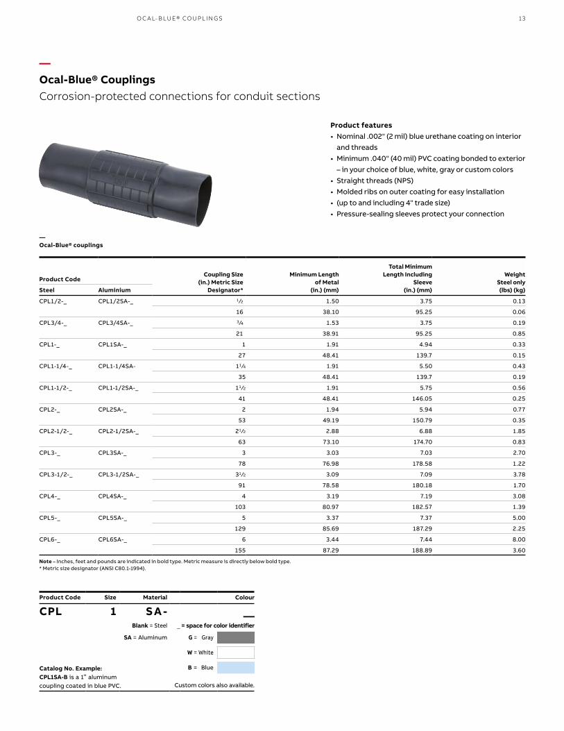
—Ocal-Blue® CouplingsCorrosion-protected connections for conduit sections
Product features• Nominal .002" (2 mil) blue urethane coating on interior
and threads• Minimum .040" (40 mil) PVC coating bonded to exterior
– in your choice of blue, white, gray or custom colors• Straight threads (NPS)• Molded ribs on outer coating for easy installation• (up to and including 4" trade size)• Pressure-sealing sleeves protect your connection
—Ocal-Blue® couplings
O C A L- B LU E® CO U PL I N G S
Coupling Size (in.) Metric Size
Designator*
Minimum Lengthof Metal
(in.) (mm)
Total MinimumLength Including
Sleeve(in.) (mm)
Weight Steel only
(lbs) (kg)
Product Code
Steel Aluminium
CPL1/2-_ CPL1/2SA-_ 1 ⁄2 1.50 3.75 0.13
16 38.10 95.25 0.06
CPL3/4-_ CPL3/4SA-_ 3 ⁄4 1.53 3.75 0.19
21 38.91 95.25 0.85
CPL1-_ CPL1SA-_ 1 1.91 4.94 0.33
27 48.41 139.7 0.15
CPL1-1/4-_ CPL1-1/4SA- 11 ⁄4 1.91 5.50 0.43
35 48.41 139.7 0.19
CPL1-1/2-_ CPL1-1/2SA-_ 11 ⁄2 1.91 5.75 0.56
41 48.41 146.05 0.25
CPL2-_ CPL2SA-_ 2 1.94 5.94 0.77
53 49.19 150.79 0.35
CPL2-1/2-_ CPL2-1/2SA-_ 21 ⁄2 2.88 6.88 1.85
63 73.10 174.70 0.83
CPL3-_ CPL3SA-_ 3 3.03 7.03 2.70
78 76.98 178.58 1.22
CPL3-1/2-_ CPL3-1/2SA-_ 31 ⁄2 3.09 7.09 3.78
91 78.58 180.18 1.70
CPL4-_ CPL4SA-_ 4 3.19 7.19 3.08
103 80.97 182.57 1.39
CPL5-_ CPL5SA-_ 5 3.37 7.37 5.00
129 85.69 187.29 2.25
CPL6-_ CPL6SA-_ 6 3.44 7.44 8.00
155 87.29 188.89 3.60
Note – Inches, feet and pounds are indicated in bold type. Metric measure is directly below bold type.* Metric size designator (ANSI C80.1-1994).
Product Code Size Material
CPL 1 S A - __Blank = Steel _ = space for color identifier
SA = Aluminum G = Gray
W = White
Catalog No. Example: CPL1SA-B is a 1" aluminum
coupling coated in blue PVC.
B = Blue
Custom colors also available.
Colour

14 O C A L® CO R R OSI O N - R E SIS TA NT CO N D U IT S Y S TEMS
TCC Split Coupling
Pipe Size(in.)
Metric SizeDesignator*Product Code
TCC1-_ 1 ⁄2 16
TCC2-_ 3 ⁄4 21
TCC3-_ 1 27
TCC4-_ 11 ⁄4 35
TCC5-_ 11 ⁄2 41
TCC6-_ 2 53
* Metric size designator (ANSI C80.1-1994).
Pipe Size(in.)
Metric SizeDesignator*Product Code
TCC7-_ 21 ⁄2 63
TCC8-_ 3 78
TCC9-_ 31 ⁄2 91
TCC10-_ 4 103
TCC12-_ 5 129
TCC14-_ 6 155
* Metric size designator (ANSI C80.1-1994).
—Ocal-Blue® double-coat split couplings
Product Code Size
TCC 1 ___ = space for color identifier
G = Gray
W = White
B = Blue
Custom colors also available.
Colour
Note: The use of standard couplings is recommended whenever possible due to better overall corrosion protection..
Split couplings serve as speed unions for cost-effective joining of two separate lengths of threaded conduit. Like other Ocal® fittings, they’re double coated in urethane and PVC to help safeguard your entire conduit system againstcorrosion.
Product features• Malleable iron construction• Nominal .002" (2 mil) blue urethane on both interior
and exterior• Minimum .040" (40 mil) PVC bonded to exterior• PVC coating in your choice of blue, white and gray
standard colors with custom colors available on request
• Stainless steel hardware included separately
—Ocal-Blue® Double-coat split couplingsJoin threaded conduit where you can’t use a standard coupling

15
—Ocal-Blue® NipplesSpeed up your field installations with pre-threaded conduit nipples
Product features• Made from Ocal® PVC-coated steel or aluminum
conduit• Blue urethane coating over threads• Nominal .002" (2 mil) blue urethane on interior• Minimum .040" (40 mil) PVC coating on exterior –
choose blue, white, gray or custom colors• Color-coded thread protectors for easy identification
of conduit size• Available in 11 standard lengths – close and 2" to 12"
with custom lengths available on request• Close nipples are coated only in urethane
O C A L- B LU E® N I PPL E S
Pipe Size (in.)MetricSize*
Nipple Length (in.) (mm)
2" 21⁄2" 3" 31⁄2 4" 5" 6" 8" 10" 12"Close 50.8 63.5 76.2 88.9 101.6 127.0 152.4 203.2 254.0 304.8
1 ⁄2" CLNPL1/2-_ NPL1/2X2-_ NPL1/2X21/2-_ NPL1/2X3- NPL1/2X31/2-_ NPL1/2X4-_ NPL1/2X5-_ NPL1/2X6-_ NPL1/2X8-_ NPL1/2X10-_ NPL1/2X12-_
16
3 ⁄4" CLNPL3/4-_ NPL3/4X2-_ NPL3/4X21/2-_ NPL3/4X3-_ NPL3/4X31/2-_ NPL3/4X4-_ NPL3/4X5-_ NPL3/4X6-_ NPL3/4X8-_ NPL3/4X10-_ NPL3/4X12-_
21
1" CLNPL1-_ NPL1X2-_ NPL1X21/2-_ NPL1X3-_ NPL1X31/2-_ NPL1X4-_ NPL1X5-_ NPL1X6-_ NPL1X8-_ NPL1X10-_ NPL1X12-_
27
11⁄4" CLNPL11/4-_ NPL11/4X2-_ NPL11/4X21/2-_ NPL11/4X3-_ NPL11/4X31/2-_ NPL11/4X4- NPL11/4X5-_ NPL11/4X6-_ NPL11/4X8-_ NPL11/4X10-_ NPL11/4X12-_
35
11⁄2" CLNPL11/2-_ NPL11/2X2-_ NPL11/2X21/2-_ NPL11/2X3-_ NPL11/2X31/2-_ NPL11/2X4-_ NPL11/2X5-_ NPL11/2X6-_ NPL11/2X8-_ NPL11/2X10-_ NPL11/2X12-_
41
2" CLNPL2-_ — NPL2X21/2-_ NPL2X3-_ NPL2X31/2-_ NPL2X4-_ NPL2X5-_ NPL2X6-_ NPL2X8-_ NPL2X10-_ NPL2X12-_
53
21⁄2" CLNPL21/2-_ — — — NPL21/2X31/2-_ NPL21/2X4-_ NPL21/2X5-_ NPL21/2X6-_ NPL21/2X8-_ NPL21/2X10-_ NPL21/2X12-_
63
3" CLNPL3-_ — — — NPL3X31/2-_ NPL3X4-_ NPL3X5-_ NPL3X6-_ NPL3X8-_ NPL3X10-_ NPL3X12-_
78
31⁄2" CLNPL31/2-_ — — — — NPL31/2X4-_ NPL31/2X5-_ NPL31/2X6-_ NPL31/2X8-_ NPL31/2X10-_ NPL31/2X12-_
91
4" CLNPL4-_ — — — — NPL4X4-_ NPL4X5-_ NPL4X6-_ NPL4X8-_ NPL4X10-_ NPL4X12-_
103
5" CLNPL5-_ — — — — — NPL5X5-_ NPL5X6-_ NPL5X8-_ NPL5X10-_ NPL5X12-_
129
6" CLNPL6-_ — — — — — NPL6X5-_ NPL6X6-_ NPL6X8-_ NPL6X10-_ NPL6X12-_
155
* Metric size designator (ANSI C80.1-1994).
—PVC-coated conduit nipples – steel
Product Code Size x Length Material
NPL 3/4 x 6 __ - __Blank = Steel _ = space for color identifier
SA = Aluminum G = Gray
W = White
Catalog No. Example: NPL3/4X6-G is a 3⁄4" x 6" long steel nipple coated in gray PVC.
B = Blue
Custom colors also available.
Colour

16 O C A L® CO R R OSI O N - R E SIS TA NT CO N D U IT S Y S TEMS
Pipe Size (in.)MetricSize*
Nipple Length (in.) (mm)
2" 21⁄2" 3" 31⁄2" 4" 5" 6" 8" 10" 12"Close 50.8 63.5 76.2 88.9 101.6 127.0 152.4 203.2 254.0 304.8
1 ⁄2" CLNPL1/2SA-_ NPL1/2X2SA-_ NPL1/2X21/2SA-_ NPL1/2X3SA-_ NPL1/2X31/2SA-_ NPL1/2X4SA-_ NPL1/2X5SA-_ NPL1/2X6SA-_ NPL1/2X8SA-_ NPL1/2X10SA-_ NPL1/2X12SA-_
16
3 ⁄4" CLNPL3/4SA-_ NPL3/4X2SA-_ NPL3/4X21/2SA-_ NPL3/4X3SA-_ NPL3/4X31/2SA-_ NPL3/4X4SA-_ NPL3/4X5SA-_ NPL3/4X6SA-_ NPL3/4X8SA-_ NPL3/4X10SA-_ NPL3/4X12SA-_
21
1" CLNPL1SA-_ NPL1X2SA-_ NPL1X21/2SA-_ NPL1X3SA-_ NPL1X31/2SA-_ NPL1X4SA-_ NPL1X5SA-_ NPL1X6SA-_ NPL1X8SA-_ NPL1X10SA-_ NPL1X12SA-_
27
11⁄4" CLNPL11/4SA-_ NPL11/4X2SA-_ NPL11/4X21/2SA-_ NPL11/4X3SA-_ NPL11/4X31/2SA-_ NPL11/4X4SA-_ NPL11/4X5SA-_ NPL11/4X6SA-_ NPL11/4X8SA-_ NPL11/4X10SA-_ NPL11/4X12SA-_
35
11⁄2" CLNPL11/2SA-_ NPL11/2X2SA-_ NPL11/2X21/2SA-_ NPL11/2X3SA-_ NPL11/2X31/2SA-_ NPL11/2X4SA-_ NPL11/2X5SA-_ NPL11/2X6SA-_ NPL11/2X8SA-_ NPL11/2X10SA-_ NPL11/2X12SA-_
41
2" CLNPL2SA-_ — NPL2X21/2SA-_ NPL2X3SA-_ NPL2X31/2SA-_ NPL2X4SA-_ NPL2X5SA-_ NPL2X6SA-_ NPL2X8SA-_ NPL2X10SA-_ NPL2X12SA-_
53
21⁄2" CLNPL21/2SA-_ — — — NPL21/2X31/2SA-_ NPL21/2X4SA-_ NPL21/2X5SA-_ NPL21/2X6SA-_ NPL21/2X8SA-_ NPL21/2X10SA-_ NPL21/2X12SA-_
63
3" CLNPL3SA-_ — — — NPL3X31/2SA-_ NPL3X4SA-_ NPL3X5SA-_ NPL3X6SA-_ NPL3X8SA-_ NPL3X10SA-_ NPL3X12SA-_
78
31⁄2" CLNPL31/2SA-_ — — — — NPL31/2X4SA-_ NPL31/2X5SA-_ NPL31/2X6SA-_ NPL31/2X8SA-_ NPL31/2X10SA-_ NPL31/2X12SA-_
91
4" CLNPL4SA-_ — — — — NPL4X4SA-_ NPL4X5SA-_ NPL4X6SA-_ NPL4X8SA-_ NPL4X10SA-_ NPL4X12SA-_
103
5" CLNPL5SA-_ — — — — — NPL5X5SA-_ NPL5X6SA-_ NPL5X8SA-_ NPL5X10SA-_ NPL5X12SA-_
129
6" CLNPL6SA-_ — — — — — NPL6X5SA-_ NPL6X6SA-_ NPL6X8SA-_ NPL6X10SA-_ NPL6X12SA-_
155
* Metric size designator (ANSI C80.1-1994).
—PVC-coated conduit nipples – Aluminum
Product Code Size x Length Material
NPL 3/4 x 6 __ - __Blank = Steel _ = space for color identifier
SA = Aluminum G = Gray
W = White
Catalog No. Example: NPL3/4X6-G is a 3⁄4" x 6" long steel nipple coated in gray PVC.
B = Blue
Custom colors also available.
Colour
—Ocal-Blue® Nipples (continued)

17
—Ocal-Blue® Standard-radius elbowsFactory bent to save time and materials.
Product features• Fabricated from Ocal® PVC-coated conduit• Standard radii in 30°, 45°, 60° and 90° available for
immediate shipment• Color-coded thread protectors for easy identification
of conduit size
—Ocal-Blue® Standard-radius elbows
Pipe Size
Radius “R” Offset “C”Straight End
“D” UnbentLength
Weight Steel onlyProduct Code Metric Size
Steel Aluminium (in.) Designator* (in.) (mm) (in.) (mm) (in.) (mm) (in.) (mm) (lbs) (kg)
ELL1/2-_-_ ELL1/2-_-SA-_ 1 ⁄2 16 4.00 101.60 6.00 152.40 2.00 50.80 10.28 261.19 0.67 16.95
ELL3/4-_-_ ELL3/4-_-SA-_ 3 ⁄4 21 4.50 114.30 6.50 165.10 2.00 50.80 11.07 281.14 0.95 24.07
ELL1-_-_ ELL1-_-SA-_ 1 27 5.75 146.05 8.00 203.20 2.25 57.15 13.53 343.71 1.77 44.97
ELL11/4-_-_ ELL11/4-_-SA-_ 11⁄4 35 7.25 184.15 9.50 241.30 2.25 57.15 15.89 403.56 2.55 64.80
ELL11/2-_-_ ELL11/2-_-SA-_ 11⁄2 41 8.25 209.55 11.00 279.40 2.75 69.85 18.46 468.86 3.98 101.13
ELL2-_-_ ELL2-_-SA-_ 2 53 9.50 241.30 13.00 330.20 3.50 88.90 21.92 556.83 6.33 160.86
ELL21/2-_-_ ELL21/2-_-SA-_ 21⁄2 63 10.50 266.70 14.00 355.60 3.50 88.90 23.49 596.73 9.65 245.09
ELL3-_-_ ELL3-_-SA-_ 3 78 13.00 330.20 16.50 419.10 3.50 88.90 27.42 696.48 15.42 391.77
ELL31/2-_-_ ELL31/2-_-SA-_ 31⁄2 91 15.00 381.00 20.75 527.05 5.75 146.05 35.06 890.57 23.30 591.84
ELL4-_-_ ELL4-_-SA-_ 4 103 16.00 406.40 21.75 552.45 5.75 146.05 36.63 930.47 29.68 753.80
ELL5-_-_ ELL5-_-SA-_ 5 129 24.00 609.60 31.00 787.40 7.00 177.80 51.70 1313.16 60.82 1544.89
ELL6-_-_ ELL6-_-SA-_ 6 155 30.00 762.00 39.00 990.60 9.00 228.60 65.12 1654.15 85.69 2176.51
* Metric size designator (ANSI C80.1-1994).
Product Code Pipe Size Angle Material
ELL 3/4- __ - __ - __30 = 30° Blank = Steel
45 = 45° SA = Aluminum G = Gray
60 = 60° W = White
Catalog No. Example: NPL3/4X6-G is a 3⁄4" trade size 90° aluminum elbow coated in white PVC.
B = Blue
Custom colors also available.
Colour
Blank = 90°
O C A L- B LU E® S TA N DA R D - R A D I US EL B OW S

18 O C A L® CO R R OSI O N - R E SIS TA NT CO N D U IT S Y S TEMS
—Ocal-Blue® Large-radius elbows
Radius “R” Offset “C”Straight End
“D” UnbentLengthProduct Code Pipe Size
(in.)Metric Size
Steel Aluminium Designator* (in.) (mm) (ft/in.) (mm) (in.) (mm) (ft/in.) (mm)
LRELL_X12-_-_ LRELL_X12-_-SA-_ 1-21 ⁄2 27–63 12.00 304.80 1' 9" 533.40 9.00 228.60 3' 0" 914.40
LRELL_X15-_-_ LRELL_X15-_-SA-_ 1-3 27–78 15.00 381.00 2' 0" 609.60 9.00 228.60 3' 6" 1066.80
LRELL_X18-_-_ LRELL_X18-_-SA-_ 1-4 27–103 18.00 457.20 2' 4" 711.20 10.00 254.00 4' 0" 1219.20
LRELL_X24-_-_ LRELL_X24-_-SA-_ 1-4 27–103 24.00 609.60 2' 11" 889.00 11.00 279.40 4' 11" 1498.60
LRELL_X30-_-_ LRELL_X30-_-SA-_ 1-5 27–129 30.00 762.00 3' 5" 1041.40 11.00 279.40 5' 9" 1752.60
LRELL_X36-_-_ LRELL_X36-_-SA-_ 1-6 27–155 36.00 914.40 3' 11" 1193.80 11.00 279.40 6' 6" 1981.20
LRELL_X42-_-_ LRELL_X42-_-SA-_ 1-6 27–155 42.00 1066.80 4' 6" 1371.60 12.00 304.80 7' 6" 2286.00
LRELL_X48-_-_ LRELL_X48-_-SA-_ 1-6 27–155 48.00 1219.20 5' 0" 1524.00 12.00 304.80 8' 6" 2590.80
* Metric size designator (ANSI C80.1-1994).
Product Code Pipe Size Radius Angle Material
LRELL __X 12- __ - __ - __30 = 30° Blank = Steel
45 = 45° SA = Aluminum G = Gray
60 = 60° W = White
Catalog No. Example: LRELL3X18-45-G is a 3" trade size steel elbow with radius of 18" and an angle of 45°, coated in gray PVC.
B = Blue
Custom colors also available.
Colour
Blank = 90°
—Ocal-Blue® Large-radius elbowsChoose the size and angle to meet your exact requirements
Product features• Fabricated from Ocal® PVC-coated conduit• Large radius in 90° available for immediate
shipment• Special radii and angles not listed available upon
request• Color-coded thread protectors for easy
identification of conduit size

19
Product features• Beam clamps support and attach conduit runs to
structural beams• Molded right-angle beam clamps and U-bolts provide
extra protection• Encapsulated, hex-shaped nuts fit standard wrenches• Stainless steel hardware included• Parallel (PAR) and edge (EC) clamps feature nominal
.015" (15 mil) PVC coating for corrosion protection• Right-Angle clamps (RA) and U-Bolts (UB) feature
nominal .040" (40 mil) PVC coating for corrosion protectionPVC
Parallel (PAR) Edge (EC)
Product Code
Pipe Size(in.)
Right Angle Parallel Edge
Metric Size Designator*
RA1/2-_ PAR1/2-_ EC1/2-_ 1 ⁄2 16
RA3/4-_ PAR3/4-_ EC3/4-_ 3 ⁄4 21
RA1-_ PAR1-_ EC1-_ 1 27
RA1-1/4-_ PAR1-1/4-_ EC1-1/4-_ 11 ⁄4 35
RA1-1/2-_ PAR1-1/2-_ EC1-1/2-_ 11 ⁄2 41
RA2-_ PAR2-_ EC2-_ 2 53
RA2-1/2-_ PAR2-1/2-_ — 21 ⁄2 63
RA3-_ PAR3-_ — 3 78
RA3-1/2-_ PAR3-1/2-_ — 31 ⁄2 91
RA4-_ PAR4-_ — 4 103
Product CodePipe Size
(in.)Metric Size
Designator*
“A” Dimension
(in.) (mm)
UB1/2-_ 1 ⁄2 16 1.38 34.93
UB3/4- 3 ⁄4 21 1.56 39.69
UB1-_ 1 27 1.84 46.83
UB1-1/4-_ 11 ⁄4 35 2.19 55.56
UB1-1/2-_ 11 ⁄2 41 2.50 63.5
UB2-_ 2 53 2.97 75.41
UB2-1/2-_ 21 ⁄2 63 3.47 88.11
UB3-_ 3 78 4.09 103.98
UB3-1/2-_ 31 ⁄2 91 4.59 116.68
UB4-_ 4 103 5.09 129.38
UB5-_ 5 129 6.63 168.28
UB6-_ 6 155 8.00 203.2
—PVC-coated beam clamps
—PVC-coated U-bolts
Right Angle (RA)
U-Bolt (UB)
A
Product Code Size
UB 1- ___ = space for color identifier
G = Gray
W = White
B = Blue
Custom colors also available.
Colour
Product Code
RA1- ___ = space for color identifier
G = Gray
W = White
B = Blue
Custom colors also available.
Colour
O C A L- B LU E® P VC- COATED B E A M CL A M P S A N D U - B O LTS
—Ocal® PVC-coated beam clamps and U-boltsPVC coating evenly molded around saddle prevents exposure of metal – an Ocal® exclusive

20 O C A L® CO R R OSI O N - R E SIS TA NT CO N D U IT S Y S TEMS
—Pipe StrapsSupport conduit on walls and structures
Product features• Available in malleable iron/stamped steel with nominal
.015" (15 mil) PVC coating in your choice of blue, white or gray or in 303 stainless steel
• Choose one- or two-hole versions• Sized to allow for the extra thickness of the PVC
coating
Product Code
Pipe Size(in.)
ConduitStrap I.D.
PVC-CoatedConduit O.D.One-Hole
303 S.S. StrapTwo-Hole303 S.S. Strap
Metric SizeDesignator* (in.) (mm) (in.) (mm)
TS102-SS TS902-SS 1 ⁄2 16 0.92 23.37 0.92 23.37
TS103-SS TS903-SS 3 ⁄4 21 1.16 29.46 1.13 28.70
TS104-SS TS904-SS 1 27 1.51 38.35 1.40 35.56
TS105-SS TS905-SS 11 ⁄4 35 1.74 44.20 1.74 44.20
TS106-SS TS906-SS 11 ⁄2 41 2.20 55.88 1.98 50.29
HS107-SS HS907-SS 2 53 2.88 73.15 2.46 62.48
HS108-SS HS908-SS 21 ⁄2 63 3.50 88.90 2.96 75.18
HS109-SS HS909-SS 3 78 4.00 101.60 3.98 101.09
HS110-SS HS910-SS 31 ⁄2 91 4.50 114.30 4.08 103.63
Product Code
Pipe Size(in.)
One-HoleMalleable Iron
Two-HoleStamped Steel
Metric SizeDesignator*
1HMS1/2-_ 2HS1/2-_ 1 ⁄2 16
1HMS3/4-_ 2HS3/4-_ 3 ⁄4 21
1HMS1-_ 2HS1-_ 1 27
1HMS1-1/4-_ 2HS1-1/4-_ 11 ⁄4 35
1HMS1-1/2-_ 2HS1-1/2- 11 ⁄2 41
1HMS2-_ 2HS2-_ 2 53
1HMS2-1/2-_ 2HS2-1/2-_ 21 ⁄2 63
1HMS3-_ 2HS3-_ 3 78
1HMS3-1/2-_ 2HS3-1/2-_ 31 ⁄2 91
1HMS4-_ 2HS4-_ 4 103
—303 Stainless steel pipe straps for PVC-coated conduit
—PVC-coated pipe straps
Two-hole PVC-coated pipe strap One-hole PV coated pipe ptrap
Two-hole stainless steel pipe strap One-hole stainless steel pipe strap

21
—Ocal® PVC-coated clamp-back spacersUse as spacers with one-hole pipe straps
Product features• Provides space for air flow between conduit and
mounting surface• Nominal .015" (15 mil) PVC coating for corrosion
protection
Product CodePipe Size
(in.)Metric Size
Designator*
CB1/2-_ 1 ⁄2 16
CB3/4-_ 3 ⁄4 21
CB1-_ 1 27
CB1-1/4-_ 11 ⁄4 35
CB1-1/2-_ 11 ⁄2 41
CB2-_ 2 53
CB2-1/2-_ 21 ⁄2 63
CB3-_ 3 78
CB3-1/2-_ 31 ⁄2 91
CB4-_ 4 103
—Ocal® PVC-coated clamp-back spacers
Product Code
CB1- ___ = space for color identifier
G = Gray
W = White
B = Blue
Custom colors also available.
Colour
O C A L- B LU E® P VC- COATED CL A M P - B ACK SPACER S

22 O C A L® CO R R OSI O N - R E SIS TA NT CO N D U IT S Y S TEMS
—01 3 ⁄4" T Form 8conduit bodyand cover—02 3 ⁄4" X Form 7 conduit body and cover—03 21 ⁄2" LB Form 8 conduit body and cover—04 21 ⁄2" LB Form 7 conduit body and cover—05 3 ⁄4" LB Mark 9 conduit body and cover
—03
—01
—05
—02
Product Code Material
LB27- __ __Blank = Ferrous _ = space for color identifier
SA = Aluminum G = Gray
Catalog No. Example: LB27-W is a 3⁄4" LB ferrous conduit body and cover coated in white PVC.
W = White
B = Blue
Custom colors also available.
Colour
—Ocal-Blue® Double-coat conduit bodiesEasy access for pulling, splicing, mounting and maintenance
With Ocal-Blue® Double-Coat Conduit Bodies, you can connect sections of conduit – with or without 90° bends – and provide easy access for wire pulling, making splices in branch conductors and for maintenance and future system changes. Conduit bodies can also serve as mounting outlets for wiring devices and lighting fixtures.
Product features • Type 4X Form 8 (1 ⁄2"-2") conduit bodies have
injection-molded PVC-coated cover with integral O-ring seal
• Flat surface molded on conduit body seals with molded flange on cover on 21 ⁄2"-4" Form 8 and all Form 7
• Available in Form 7 and Form 8 ferrous as well as Mark 9 and Form 7 aluminum
• All Ocal-Blue® conduit bodies offer double corrosion protection – both bodies and covers coated inside and out with a nominal .002" (2 mil) blue urethane, then exterior coated with a nominal .040" (40 mil) PVC
• PVC coating in your choice of blue, gray or white with custom colors available
• All threaded hubs fitted with pressure-sealing sleeves
• Conduit bodies ship complete with covers and encapsulated stainless steel screws
• Covers also sold separately for replacement or retrofit purposes
—04

23
—Ocal-Blue® Conduit bodiesQuick reference guide
Size (Inch and Metric Size Designator*)
Shape Style1 ⁄2"16
3 ⁄4"21
1"27
11 ⁄4"35
11 ⁄2"41
2"53
21 ⁄2"63
3"78
31 ⁄2"91
4"103
Ocal-Blue® Conduit bodies
Form 7 C17-_ C27-_ C37-_ C47-_ C57-_ C67-_ C77-_ C87-_ — —
Form 8 C18-4X-_ C28-4X-_ C38-4X-_ C448-4X-_ C58-4X-_ C68-4X-_ C78-_ C88-_ — —
Mark 9 C19-_ C29-_ C39-_ C49-_ C59-_ C69-_ C789-_ C889-_ C989-_ C1089-_
Form 7 Aluminum
C17SA-_ C27SA-_ C37SA-_ C47SA-_ C57SA-_ C67SA-_ C77SA-_ C87SA-_ — —
Form 7 LU17-_ LU27-_ LU37-_ LU47-_ LU57-_ LU67-_ — — — —
Form 8 LU18-4X-_ LU28-4X-_ LU38-4X-_ LU448-4X-_ LU58-4X-_ LU68-4X-_ — — — —
Form 7 LB17-_ LB27-_ LB37-_ LB47-_ LB57-_ LB67-_ LB777-_ LB87-_ LB97-_ LB107-_
Form 8 LB18-4X-_ LB28-4X-_ LB38-4X-_ LB448-4X-_ LB58-4X-_ LB68-4X-_ LB78-_ LB888-_ LB98-_ LB108-_
Mark 9 LB19-_ LB29-_ LB39-_ LB49-_ LB59-_ LB69-_ LB789-_ LB889-_ LB989-_ LB1089-_
Form 7 Aluminum
LB17SA-_ LB27SA-_ LB37SA-_ LB47SA-_ LB57SA-_ LB67SA-_ LB777SA-_ LB87SA-_ LB97SA-_ LB107SA-_
Form 7 LL17-_ LL27-_ LL37-_ LL47-_ LL57-_ LL67-_ LL777-_ LL87-_ LL97-_ LL107-_
Form 8 LL18-4X-_ LL28-4X-_ LL38-4X-_ LL448-4X-_ LL58-4X-_ LL68-4X-_ LL78-_ LL888-_ — —
Mark 9 LL19-_ LL29-_ LL39-_ LL49-_ LL59-_ LL69-_ LL789-_ LL889-_ LL989-_ LL1089-_
Form 7 Aluminum
LL17SA-_ LL27SA-_ LL37SA-_ LL47SA-_ LL57SA-_ LL67SA-_ LL777SA-_ LL87SA-_ LL97SA-_ LL107SA-_
Form 7 LR17-_ LR27-_ LR37-_ LR47-_ LR57-_ LR67-_ LR777-_ LR87-_ LR97-_ LR107-_
Form 8 LR18-4X-_ LR28-4X-_ LR38-4X-_ LR448-4X-_ LR58-4X-_ LR68-4X-_ LR78-_ LR888-_ — —
Mark 9 LR19-_ LR29-_ LR39-_ LR49-_ LR59-_ LR69-_ LR789-_ LR889-_ LR989-_ LR1089-_
Form 7 Aluminum
LR17SA-_ LR27SA-_ LR37SA-_ LR47SA-_ LR57SA-_ LR67SA-_ LR777SA-_ LR87SA-_ LR97SA-_ LR107SA-_
Form 7 T17-_ T27-_ T37-_ T47-_ T57-_ T67-_ T77-_ T87-_ T97-_ T107-_
Form 8 T18-4X-_ T28-4X-_ T38-4X-_ T448-4X-_ T58-4X-_ T68-4X-_ T78-_ T88-_ — —
Mark 9 T19-_ T29-_ T39-_ T49-_ T59-_ T69-_ T789-_ T889-_ T989-_ T1089-_
Form 7 Aluminum
T17SA-_ T27SA-_ T37SA-_ T47SA-_ T57SA-_ T67SA-_ T77SA-_ T87SA-_ T97SA-_ T107SA-_
Form 7 TB17-_ TB27-_ TB37-_ TB47-_ TB57-_ TB67-_ — — — —
Form 8 TB18-4X-_ TB28-4X-_ TB38-4X-_ TB448-4X-_ TB58-4X-_ TB68-4X-_ — — — —
Mark 9 TB19-_ TB29-_ TB39-_ TB49-_ — — — — — —
Form 7 Aluminum
TB17SA-_ TB27SA-_ TB37SA-_ TB47SA-_ TB57SA-_ TB67SA-_ — — — —
Form 7 X17-_ X27-_ X37-_ X47-_ X57-_ X67-_ — — — —
Form 8 X18-4X-_ X28-4X-_ X38-4X-_ X448-4X-_ X58-4X-_ X68-4X-_ — — — —
Mark 9 X19-_ X29-_ X39-_ — — — — — — —
Form 7 Aluminum
X17SA-_ X27SA-_ X37SA-_ X47SA-_ X57SA-_ X67SA-_ — — — —
Note - Fittings shown uncoated
Ocal-Blue® Conduit body covers
Form 7 170F-_ 270F-_ 370F-_ 470F-_ 570F-_ 670F-_ 870F-_ 870F-_ 970F-_ 970F-_
Form 8 180F-4X-_ 280F-4X-_ 380F-4X-_ 480F-4X-_ 580F-4X-_ 680F-4X-_ 880F-_ 880F-_ 980F-_ 980F-_
Mark 9 190-_ 290-_ 390-_ 490-_ 590-_ 690-_ 889-_ 889-_ 989-_ 989-_
Form 7 Aluminum
170SA-_ 270SA-_ 370SA-_ 470SA-_ 570SA-_ 670SA-_ 870SA-_ 870SA-_ 970SA-_ 970SA-_
* Metric size designator (ANSI C80.1-1994).
—Ocal-Blue® Conduit bodies and covers - quick reference
C
LU
LB
LL
LR
TT
TB
X
O C A L- B LU E® CO N D U IT B O D IE S

24 O C A L® CO R R OSI O N - R E SIS TA NT CO N D U IT S Y S TEMS
—Ocal-Blue® Conduit bodiesWith covers – C shape
Dimensions (in. and mm)**Vol. Cap.
(cu.in./(cu/cm.)
Product Code
HubSize* A B C D E
C17-_ 1 ⁄2" 5.45 1.40 1.45 0.95 3.20 4.00
16 138.43 35.56 36.83 24.13 81.28 65.55
C27-_ 3 ⁄4" 6.05 1.60 1.65 1.15 3.80 6.6
21 153.67 40.64 41.91 29.21 96.52 108.15
C37-_ 1" 6.75 1.90 1.8 1.35 4.55 10.6
27 171.45 48.26 45.72 34.29 115.57 173.7
C47-_ 11 ⁄4" 7.30 2.30 2.20 1.80 5.00 18.8
35 185.42 58.42 55.88 45.72 127.00 308.08
C57-_ 11 ⁄2" 8.60 2.60 2.45 2.05 5.45 26.4
41 218.44 66.04 62.23 52.07 138.43 432.62
C67-_ 2" 9.50 3.20 3.05 2.45 6.40 51.00
53 241.3 81.28 77.47 62.23 162.56 835.74
C77-_ 21 ⁄2" 12.10 3.65 4.25 3.60 8.40 102.00
63 307.34 92.71 107.95 91.44 213.36 1671.48
C87-_ 3" 12.10 4.40 4.25 3.60 8.40 132.00
78 307.34 111.76 107.95 91.44 213.36 2163.09
Dimensions (in. and mm)**Vol. Cap.
(cu.in./(cu/cm.)
Product Code
HubSize* A B C D E
C18-4X-_ 1 ⁄2" 5.53 1.44 1.38 1.00 3.31 4.90
16 140.49 36.51 34.93 25.4 84.14 80.3
C28-4X-_ 3 ⁄4" 6.28 1.53 1.19 1.19 3.94 8.00
21 159.54 38.89 30.16 30.16 100.01 131.1
C38-4X-_ 1" 7.31 1.94 1.75 1.38 4.56 13.00
27 185.74 49.21 44.45 34.93 115.89 213.03
C448-4X-_ 11 ⁄4" 8.50 2.38 2.19 1.75 5.31 23.50
35 215.9 60.33 55.56 44.45 134.94 385.1
C58-4X-_ 11 ⁄2" 10.38 2.78 2.75 2.13 6.50 45.00
41 263.53 70.64 69.85 53.98 165.1 737.42
C68-4X-_ 2" 12.25 3.56 3.75 3.00 8.56 88.00
53 311.15 90.49 95.25 76.2 217.49 1442.06
C78-_ 21 ⁄2" 15.63 4.44 5.00 4.25 10.88 110.00
63 396.88 112.71 127.00 107.95 276.23 1802.58
C88-_ 3" 15.63 4.81 5.00 4.25 10.88 110.00
78 396.88 122.24 127.00 107.95 276.23 1802.58
* Metric size designator (ANSI C80.1-1994).** Dimensions shown are for uncoated conduit bodies.
Dimensions (in. and mm)**Vol. Cap.
(cu.in./(cu/cm.)
Product Code
HubSize* A B C D E
C19-_ 1 ⁄2" 5.00 1.38 1.38 1.19 3.31 —
16 127 35.05 35.05 30.23 84.07 —
C29-_ 3 ⁄4" 5.69 1.63 1.56 1.38 3.94 —
21 144.53 41.4 39.62 35.05 100.08 —
C39-_ 1" 6.59 1.88 1.75 1.50 4.56 —
27 167.39 47.75 44.45 38.10 115.82 —
C49-_ 11 ⁄4" 7.50 2.50 2.19 1.94 5.31 —
35 190.5 63.5 55.63 49.28 134.87 —
C59-_ 11 ⁄2" 8.25 2.75 2.50 2.25 6.00 —
41 209.55 69.85 63.5 57.15 152.4 —
C69-_ 2" 10.50 3.44 3.19 2.88 8.06 —
53 266.7 87.38 81.03 73.15 204.72 —
C789-_ 21 ⁄2" 15.63 4.44 5.00 4.25 10.88 —
63 397.00 112.78 127.00 107.95 276.35 —
C889-_ 3" 15.63 4.81 5.00 4.25 10.88 —
78 397.00 122.17 127.00 107.95 276.35 —
C989-_ 31 ⁄2" 18.75 5.69 6.25 5.44 13.44 —
91 476.25 144.53 158.75 138.18 341.38 —
C1089-_ 4" 18.75 5.94 6.25 5.44 13.44 —
103 476.25 150.88 158.75 138.18 341.38 —
Dimensions (in. and mm)**Vol. Cap.
(cu.in./(cu/cm.)
Product Code
HubSize* A B C D E
C17SA-_ 1 ⁄2" 5.45 1.40 1.45 0.95 3.20 4.00
16 138.43 35.56 36.83 24.13 81.28 65.55
C27SA-_ 3 ⁄4" 6.05 1.60 1.65 1.15 3.80 6.60
21 153.67 40.64 41.91 29.21 96.52 108.15
C37SA-_ 1" 6.75 1.90 1.80 1.35 4.55 10.60
27 171.45 48.26 45.72 34.29 115.57 173.7
C47SA-_ 11 ⁄4" 7.30 2.30 2.20 1.80 5.00 18.80
35 185.42 58.42 55.88 45.72 127.00 308.08
C57SA-_ 11 ⁄2" 8.60 2.60 2.45 2.05 5.45 26.40
41 218.44 66.04 62.23 52.07 138.43 432.62
C67SA-_ 2" 9.50 3.20 3.05 2.45 6.40 51.00
53 241.30 81.28 77.47 62.23 162.56 835.74
C77SA-_ 21 ⁄2" 12.10 3.65 4.25 3.60 8.40 102.00
63 307.34 92.71 107.95 91.44 213.36 1671.48
C87SA-_ 3" 12.10 4.40 4.25 3.60 8.40 132.00
78 307.34 111.76 107.95 91.44 213.36 2163.09
—C Form 7 Ferrous conduit bodies with covers
—C Form 8 Ferrous conduit bodies with covers
—C Mark 9 Aluminum conduit bodies with covers
—C Form 7 Aluminum conduit bodies with covers
A
B C
E
D
C C

25
—Ocal-Blue® Conduit bodiesWith covers – LB shape
Dimensions (in. and mm)**Vol. Cap.
(cu.in./(cu/cm.)
Product Code
HubSize* A B C D E
LB17-_ 1 ⁄2" 4.60 2.20 1.35 0.95 3.20 4.00
16 116.84 55.88 34.29 24.13 81.28 65.55
LB27-_ 3 ⁄4" 5.25 2.40 1.65 1.15 3.80 6.60
21 133.35 60.96 41.91 29.21 96.52 108.15
LB37-_ 1" 6.00 2.65 1.80 1.35 4.55 10.6
27 152.4 67.31 45.72 34.29 115.57 173.7
LB47-_ 11 ⁄4" 6.45 3.20 2.20 1.80 5.00 18.80
35 163.83 81.28 55.88 45.72 127.00 308.08
LB57-_ 11 ⁄2" 7.25 3.90 2.45 2.05 5.45 26.4.00
41 184.15 99.06 62.23 52.07 138.43 432.62
LB67-_ 2" 8.30 4.45 3.10 2.45 6.40 51.00
53 210.82 113.03 78.74 62.23 162.56 835.74
LB777-_ 21 ⁄2" 10.55 5.20 4.25 3.60 8.40 102.00
63 267.97 132.08 107.95 91.44 213.36 1671.48
LB87-_ 3" 10.55 5.95 4.25 3.60 8.40 132.00
78 267.97 151.13 107.95 91.44 213.36 2163.09
LB97-_ 31 ⁄2" 12.85 6.70 5.25 4.55 10.25 210.00
91 326.39 170.18 133.35 115.57 260.35 3441.28
LB107-_ 4" 12.85 7.20 5.25 4.55 10.25 243.00
103 326.39 182.88 133.35 115.57 260.35 3982.06
Dimensions (in. and mm)**Vol. Cap.
(cu.in./(cu/cm.)
Product Code
HubSize* A B C D E
LB18-4X-_ 1 ⁄2" 4.94 2.22 1.38 1.00 3.31 4.90
16 125.41 56.36 34.93 25.4 84.14 80.3
LB28-4X-_ 3 ⁄4" 5.56 2.44 1.56 1.19 3.31 8.00
21 141.29 61.93 39.69 30.16 84.14 131.1
LB38-4X-_ 1" 6.50 2.81 1.75 1.38 4.56 13.00
27 165.1 71.45 44.45 34.93 115.89 213.03
LB448-4X-_ 11 ⁄4" 7.53 3.34 2.19 1.75 5.31 23.50
35 191.29 84.93 55.56 44.45 134.94 385.1
LB58-4X-_ 11 ⁄2" 9.13 4.03 2.75 2.13 6.50 45.00
41 231.78 102.39 69.85 53.98 165.1 737.42
LB68-4X-_ 2" 11.00 4.41 3.75 3.00 8.56 88.00
53 279.4 111.92 95.25 76.2 217.49 1442.06
LB78-_ 21 ⁄2" 13.94 6.13 5.00 4.25 10.88 110.00
63 354.01 155.58 127.00 107.95 276.23 1802.58
LB888-_ 3" 13.94 6.50 5.00 4.25 10.88 110.00
78 354.01 165.1 127.00 107.95 276.23 1802.58
LB98-_ 31 ⁄2" 16.88 7.56 6.25 5.44 13.44 250.00
91 428.63 192.09 158.75 138.11 341.31 4096.77
LB108-_ 4" 16.88 7.81 6.25 5.44 13.44 250.00
103 428.63 198.44 158.75 138.11 341.31 4096.77
* Metric size designator (ANSI C80.1-1994).** Dimensions shown are for uncoated conduit bodies.
Dimensions (in. and mm)**Vol. Cap.
(cu.in./(cu/cm.)
Product Code
HubSize* A B C D E
LB19-_ 1 ⁄2" 4.59 2.13 1.38 1.19 3.31 —
16 116.68 53.98 34.93 30.16 84.14 —
LB29-_ 3 ⁄4" 5.25 2.41 1.56 1.38 3.94 —
21 133.35 61.12 39.69 34.93 100.01 —
LB39-_ 1" 6.09 2.84 1.75 1.5 4.56 —
27 154.78 72.23 44.45 38.1 115.89 —
LB49-_ 11 ⁄4" 7.03 3.47 2.19 1.94 5.31 —
35 178.59 88.11 55.56 49.21 134.94 —
LB59-_ 11 ⁄2" 7.75 3.75 2.50 2.25 6.00 —
41 196.85 95.25 63.5 57.15 152.4 —
LB69-_ 2" 10.03 4.47 3.19 2.88 8.06 —
53 254.79 113.51 80.96 73.03 204.79 —
LB789-_ 21 ⁄2" 13.94 6.13 5.00 4.25 10.88 —
63 354.01 155.58 127.00 107.95 276.23 —
LB889-_ 3" 13.94 6.50 5.00 4.25 10.88 —
78 354.01 165.1 127.00 107.95 276.23 —
LB989-_ 31 ⁄2" 16.88 7.56 6.25 5.44 13.44 —
91 428.63 192.09 158.75 138.11 341.31 —
LB1089-_ 4" 16.88 7.81 6.25 5.44 13.44 —
103 428.63 198.44 158.75 138.11 341.31 —
Dimensions (in. and mm)**Vol. Cap.
(cu.in./(cu/cm.)
Product Code
HubSize* A B C D E
LB17SA-_ 1 ⁄2" 4.60 2.20 1.35 0.95 3.20 4.00
16 116.84 55.88 34.29 24.13 81.28 65.55
LB27SA-_ 3 ⁄4" 5.25 2.40 1.65 1.15 3.80 6.60
21 133.35 60.96 41.91 29.21 96.52 108.15
LB37SA-_ 1" 6.00 2.65 1.80 1.35 4.55 10.60
27 152.4 67.31 45.72 34.29 115.57 173.7
LB47SA-_ 11 ⁄4" 6.45 3.20 2.20 1.80 5.00 18.80
35 163.83 81.28 55.88 45.72 127.00 308.08
LB57SA-_ 11 ⁄2" 7.25 3.90 2.45 2.05 5.45 26.40
41 184.15 99.06 62.23 52.07 138.43 432.62
LB67SA-_ 2" 8.30 4.45 3.10 2.45 6.40 51.00
53 210.82 113.03 78.74 62.23 162.56 835.74
LB777SA-_ 21 ⁄2" 10.55 5.20 4.25 3.60 8.40 102.00
63 267.97 132.08 107.95 91.44 213.36 1671.48
LB87SA-_ 3" 10.55 5.95 4.25 3.60 8.40 132.00
78 267.97 151.13 107.95 91.44 213.36 2163.09
LB97SA-_ 31 ⁄2" 12.85 6.70 5.25 4.55 10.25 210.00
91 326.39 170.18 133.35 115.57 260.35 3441.28
LB107SA-_ 4" 12.85 7.20 5.25 4.55 10.25 243.00
103 326.39 182.88 133.35 115.57 260.35 3982.06
—LB Form 7 Ferrous conduit bodies with covers
—LB Form 8 Ferrous conduit bodies with covers
—LB Mark 9 Aluminum conduit bodies with covers
—LB Form 7 Aluminum conduit bodies with covers
A
B C
E
D
LB LB
O C A L- B LU E® CO N D U IT B O D IE S

26 O C A L® CO R R OSI O N - R E SIS TA NT CO N D U IT S Y S TEMS
—Ocal-Blue® Conduit bodiesWith covers – LL shape
Dimensions (in. and mm)**Vol. Cap.
(cu.in./(cu/cm.)
Product Code
HubSize* A B C D E
LL17-_ 1 ⁄2" 4.60 1.40 1.45 0.95 3.20 4.00
16 116.84 35.56 36.83 24.13 81.28 65.55
LL27-_ 3 ⁄4" 5.25 1.60 1.65 1.15 3.80 6.60
21 133.35 40.64 41.91 29.21 96.52 108.15
LL37-_ 1" 6.00 1.90 2.60 1.35 4.55 10.60
27 152.40 48.26 66.04 34.29 115.57 173.70
LL47-_ 11 ⁄4" 6.45 2.30 3.05 1.80 5.00 18.60
35 163.83 58.42 77.47 45.72 127.00 304.8
LL57-_ 11 ⁄2" 7.90 2.60 3.80 2.05 5.45 26.40
41 200.66 66.04 96.52 52.07 138.43 432.62
LL67-_ 2" 8.30 3.20 4.25 2.45 6.40 51.00
53 210.82 81.28 107.95 62.23 162.56 835.74
LL777-_ 21 ⁄2" 10.55 3.65 5.80 3.60 8.40 102.00
63 267.97 92.71 147.32 91.44 213.36 1671.48
LL87-_ 3" 10.55 4.40 5.80 3.60 8.40 132.00
78 267.97 111.76 147.32 91.44 213.36 2163.09
LL97-_ 31 ⁄2" 12.85 4.90 7.03 4.55 10.25 210.00
91 326.39 124.46 178.56 115.57 260.35 3441.28
LL107-_ 4" 12.85 5.40 7.03 4.55 10.25 243.00
103 326.39 137.16 178.56 115.57 260.35 3982.06
Dimensions (in. and mm)**Vol. Cap.
(cu.in./(cu/cm.)
Product Code
HubSize* A B C D E
LL19-_ 1 ⁄2" 4.59 1.38 2.13 1.19 3.31 —
16 116.68 34.93 53.98 30.16 84.14 —
LL29-_ 3 ⁄4" 5.25 1.63 2.38 1.38 3.94 —
21 133.35 41.28 60.33 34.93 100.01 —
LL39-_ 1" 6.09 1.88 2.63 1.50 4.56 —
27 154.78 47.63 66.68 38.1 115.89 —
LL49-_ 11 ⁄4" 7.03 2.50 3.09 1.94 5.31 —
35 178.59 63.5 78.58 49.21 134.94 —
LL59-_ 11 ⁄2" 7.75 2.75 3.44 2.25 6.00 —
41 196.85 69.85 87.31 57.15 152.4 —
LL69-_ 2" 10.03 3.44 4.13 2.88 8.06 —
53 254.79 87.31 104.78 73.03 204.79 —
LL789-_ 21 ⁄2" 13.94 4.44 6.69 4.25 10.88 —
63 354.01 112.71 169.86 107.95 276.23 —
LL889-_ 3" 13.94 4.81 6.69 4.25 10.88 —
78 354.08 122.24 169.93 107.95 276.35 —
LL989-_ 31 ⁄2" 16.88 5.69 8.13 5.44 13.44 —
91 428.63 144.46 206.38 138.11 341.31 —
LL1089-_ 4" 16.88 5.94 8.13 5.44 13.44 —
103 428.63 150.81 206.38 138.11 341.31 —
—LL Form 7 Ferrous conduit bodies with covers
—LL Mark 9 Aluminum conduit bodies with covers
Dimensions (in. and mm)**Vol. Cap.
(cu.in./(cu/cm.)
Product Code
HubSize* A B C D E
LL18-4X-_ 1 ⁄2" 4.94 1.44 2.16 1.00 3.31 4.90
16 125.41 36.51 54.77 25.40 84.14 80.30
LL28-4X-_ 3 ⁄4" 5.56 1.69 2.31 1.19 3.94 8.00
21 141.29 42.86 58.74 30.16 100.01 131.10
LL38-4X-_ 1" 6.47 1.94 2.63 1.38 4.56 13.00
27 164.31 49.21 66.68 34.93 115.89 213.03
LL448-4X-_ 11 ⁄4" 7.53 2.38 3.16 1.75 5.31 23.50
35 191.29 60.33 80.17 44.45 134.94 385.10
LL58-4X-_ 11 ⁄2" 9.13 2.78 4.00 2.13 6.50 45.00
41 231.78 70.64 101.6 53.98 165.10 737.42
LL68-4X-_ 2" 11.00 3.56 5.00 3.00 8.56 88.00
53 279.4 90.49 127.00 76.20 217.49 1442.06
LL78-_ 21 ⁄2" 13.94 4.44 6.69 4.25 10.88 110.00
63 354.01 112.71 169.86 107.95 276.23 1802.58
LL888-_ 3" 13.94 4.81 6.69 4.25 10.88 110.00
78 354.01 122.24 169.86 107.95 276.23 1802.58
* Metric size designator (ANSI C80.1-1994).** Dimensions shown are for uncoated conduit bodies.
Dimensions (in. and mm)**Vol. Cap.
(cu.in./(cu/cm.)
Product Code
HubSize* A B C D E
LL17SA-_ 1 ⁄2" 4.60 1.40 1.45 0.95 3.20 4.00
16 116.84 35.56 36.83 24.13 81.28 65.55
LL27SA-_ 3 ⁄4" 5.25 1.60 1.65 1.15 3.80 6.60
21 133.35 40.64 41.91 29.21 96.52 108.15
LL37SA-_ 1" 6.00 1.90 2.60 1.35 4.55 10.60
27 152.40 48.26 66.04 34.29 115.57 173.7
LL47SA-_ 11 ⁄4" 6.45 2.30 3.05 1.80 5.00 18.60
35 163.83 58.42 77.47 45.72 127.00 304.8
LL57SA-_ 11 ⁄2" 7.90 2.60 3.80 2.05 5.45 26.40
41 200.66 66.04 96.52 52.07 138.43 432.62
LL67SA-_ 2" 8.30 3.20 4.25 2.45 6.40 51.00
53 210.82 81.28 107.95 62.23 162.56 835.74
LL777SA-_ 21 ⁄2" 10.55 3.65 5.80 3.60 8.40 102.00
63 267.97 92.71 147.32 91.44 213.36 1671.48
LL87SA-_ 3" 10.55 4.40 5.80 3.60 8.40 132.00
78 267.97 111.76 147.32 91.44 213.36 2163.09
LL97SA-_ 31 ⁄2" 12.85 4.90 7.03 4.55 10.25 210.00
91 326.39 124.46 178.56 115.57 260.35 3441.28
LL107SA-_ 4" 12.85 5.40 7.03 4.55 10.25 243.00
103 326.39 137.16 178.56 115.57 260.35 3982.06
—LL Form 8 Ferrous conduit bodies with covers
—LL Form 7 Aluminum conduit bodies with covers
A
B CD
E
LL LL

27
—Ocal-Blue® Conduit bodiesWith covers – LR shape
Dimensions (in. and mm)**Vol. Cap.
(cu.in./(cu/cm.)
Product Code
HubSize* A B C D E
LR17-_ 1 ⁄2" 4.60 1.40 1.45 0.95 3.20 4.00
16 116.84 35.56 36.83 24.13 81.28 65.55
LR27-_ 3 ⁄4" 5.25 1.60 1.65 1.15 3.80 6.60
21 133.35 40.64 41.91 29.21 96.52 108.15
LR37-_ 1" 6.00 1.90 2.60 1.35 4.55 10.60
27 152.4 48.26 66.04 34.29 115.57 173.70
LR47-_ 11 ⁄4" 6.45 2.30 3.05 1.80 5.00 18.80
35 163.83 58.42 77.47 45.72 127.00 308.08
LR57-_ 11 ⁄2" 7.90 2.60 3.80 2.05 5.45 26.40
41 200.66 66.04 96.52 52.07 138.43 432.62
LR67-_ 2" 8.30 3.20 4.25 2.45 6.40 51.00
53 210.82 81.28 107.95 62.23 162.56 835.74
LR777-_ 21 ⁄2" 10.55 3.65 5.80 3.60 8.40 102.00
63 267.97 92.71 147.32 91.44 213.36 1671.48
LR87-_ 3" 10.55 4.40 5.80 3.60 8.40 132.00
78 267.97 111.76 147.32 91.44 213.36 2163.09
LR97-_ 31 ⁄2" 12.85 4.90 7.03 4.55 10.25 210.00
91 326.39 124.46 178.56 115.57 260.35 3441.28
LR107-_ 4" 12.85 5.40 7.03 4.55 10.25 243.00
103 326.39 137.16 178.56 115.57 260.35 3982.06
Dimensions (in. and mm)**Vol. Cap.
(cu.in./(cu/cm.)
Product Code
HubSize* A B C D E
LR19-_ 1 ⁄2" 4.59 1.38 2.13 1.19 3.31 —
16 116.68 34.93 53.98 30.16 84.14 —
LR29-_ 3 ⁄4" 5.25 1.63 2.38 1.38 3.94 —
21 133.35 41.28 60.33 34.93 100.01 —
LR39-_ 1" 6.09 1.88 2.63 1.50 4.56 —
27 154.78 47.63 66.68 38.1 115.89 —
LR49-_ 11 ⁄4" 7.03 2.50 3.09 1.94 5.31 —
35 178.59 63.5 78.58 49.21 134.94 —
LR59-_ 11 ⁄2" 7.75 2.75 3.44 2.25 6.00 —
41 196.85 69.85 87.31 57.15 152.4 —
LR69-_ 2" 10.03 3.44 4.13 2.88 8.06 —
53 254.79 87.31 104.78 73.03 204.79 —
LR789-_ 21 ⁄2" 13.94 4.44 6.69 4.25 10.88 —
63 354.01 112.71 169.86 107.95 276.23 —
LR889-_ 3" 13.94 4.81 6.69 4.25 10.88 —
78 354.08 122.24 169.93 107.95 276.35 —
LR989-_ 31 ⁄2" 16.88 5.69 8.13 5.44 13.44 —
91 428.63 144.46 206.38 138.11 341.31 —
LR1089-_ 4" 16.88 5.94 8.13 5.44 13.44 —
103 428.63 150.81 206.38 138.11 341.31 —
—LR Form 7 Ferrous conduit bodies with covers
—LR Mark 9 Aluminum conduit bodies with covers
Dimensions (in. and mm)**Vol. Cap.
(cu.in./(cu/cm.)
Product Code
HubSize* A B C D E
LR18-4X-_ 1 ⁄2" 4.94 1.44 2.16 1.00 3.31 4.90
16 125.41 36.51 54.77 25.4 84.14 80.30
LR28-4X-_ 3 ⁄4" 5.56 1.69 2.31 1.19 3.94 8.00
21 141.29 42.86 58.74 30.16 100.01 131.10
LR38-4X-_ 1" 6.47 1.94 2.63 1.38 4.56 13.00
27 164.31 49.21 66.68 34.93 115.89 213.03
LR448-4X-_ 11 ⁄4" 7.53 2.38 3.16 1.75 5.31 23.50
35 191.29 60.33 80.17 44.45 134.94 385.10
LR58-4X-_ 11 ⁄2" 9.13 2.78 4.00 2.13 6.50 45.00
41 231.78 70.64 101.6 53.98 165.10 737.42
LR68-4X-_ 2" 11.00 3.56 5.00 3.00 8.56 88.00
53 279.40 90.49 127.00 76.2 217.49 1442.06
LR78-_ 21 ⁄2" 13.94 4.44 6.69 4.25 10.88 110.00
63 354.01 112.71 169.86 107.95 276.23 1802.58
LR888-_ 3" 13.94 4.81 6.69 4.25 10.88 110.00
78 354.01 122.24 169.86 107.95 276.23 1802.58
* Metric size designator (ANSI C80.1-1994).** Dimensions shown are for uncoated conduit bodies.
Dimensions (in. and mm)**Vol. Cap.
(cu.in./(cu/cm.)
Product Code
HubSize* A B C D E
LR17SA-_ 1 ⁄2" 4.60 1.40 1.45 0.95 3.20 4.00
16 116.84 35.56 36.83 24.13 81.28 65.55
LR27SA-_ 3 ⁄4" 5.25 1.60 1.65 1.15 3.80 6.60
21 133.35 40.64 41.91 29.21 96.52 108.15
LR37SA-_ 1" 6.00 1.90 2.60 1.35 4.55 10.60
27 152.4 48.26 66.04 34.29 115.57 173.70
LR47SA-_ 11 ⁄4" 6.45 2.30 3.05 1.80 5.00 18.80
35 163.83 58.42 77.47 45.72 127.00 308.08
LR57SA-_ 11 ⁄2" 7.9 2.60 3.80 2.05 5.45 26.40
41 200.66 66.04 96.52 52.07 138.43 432.62
LR67SA-_ 2" 8.30 3.20 4.25 2.45 6.40 51.00
53 210.82 81.28 107.95 62.23 162.56 835.74
LR777SA-_ 21 ⁄2" 10.55 3.65 5.80 3.60 8.40 102.00
63 267.97 92.71 147.32 91.44 213.36 1671.48
LR87SA-_ 3" 10.55 4.40 5.80 3.60 8.40 132.00
78 267.97 111.76 147.32 91.44 213.36 2163.09
LR97SA-_ 31 ⁄2" 12.85 4.9 7.03 4.55 10.25 210.00
91 326.39 124.46 178.56 115.57 260.35 3441.28
LR107SA-_ 4" 12.85 5.40 7.03 4.55 10.25 243.00
103 326.39 137.16 178.56 115.57 260.35 3982.06
—LR Form 8 Ferrous conduit bodies with covers
—LR Form 7 Aluminum conduit bodies with covers
A
B CD
E
LR LR
O C A L- B LU E® CO N D U IT B O D IE S

28 O C A L® CO R R OSI O N - R E SIS TA NT CO N D U IT S Y S TEMS
—Ocal-Blue® Conduit bodiesWith covers – T shape
Dimensions (in. and mm)**Vol. Cap.
(cu.in./(cu/cm.)
Product Code
HubSize* A B C D E
T17-_ 1 ⁄2" 5.60 1.80 2.35 0.95 3.20 6.00
16 142.24 45.72 59.69 24.13 81.28 98.32
T27-_ 3 ⁄4" 6.20 2.00 2.60 1.15 3.80 9.10
21 157.48 50.80 66.04 29.21 96.52 149.12
T37-_ 1" 7.35 2.30 3.10 1.35 4.55 16.90
27 186.69 58.42 78.74 34.29 115.57 276.94
T47-_ 11 ⁄4" 7.30 2.30 3.05 1.80 5.00 19.30
35 185.42 58.42 77.47 45.72 127.00 316.27
T57-_ 11 ⁄2" 8.60 2.60 3.80 2.05 5.45 27.50
41 218.44 66.04 96.52 52.07 138.43 450.64
T67-_ 2" 9.50 3.20 4.25 2.45 6.40 50.00
53 241.3 81.28 107.95 62.23 162.56 819.35
T77-_ 21 ⁄2" 12.10 3.65 5.80 3.60 8.40 102.00
63 307.34 92.71 147.32 91.44 213.36 1671.48
T87-_ 3" 12.10 4.40 5.80 3.60 8.40 132.00
78 307.34 111.76 147.32 91.44 213.36 2163.09
T97-_ 31 ⁄2" 14.65 4.90 7.05 4.55 10.25 210.00
91 372.11 124.46 179.07 115.57 260.35 3441.28
T107-_ 4" 14.65 5.40 7.05 4.55 10.25 243.00
103 372.11 137.16 179.07 115.57 260.35 3982.06
Dimensions (in. and mm)**Vol. Cap.
(cu.in./(cu/cm.)
Product Code
HubSize* A B C D E
T19-_ 1 ⁄2" 50.00 1.38 2.13 1.19 3.31 —
16 127 34.93 53.98 30.16 84.14 —
T29-_ 3 ⁄4" 5.69 1.63 2.38 1.38 3.94 —
21 144.46 41.28 60.33 34.93 100.01 —
T39-_ 1" 6.59 1.88 2.63 1.50 4.56 —
27 167.48 47.63 66.68 38.1 115.89 —
T49-_ 11 ⁄4" 7.50 2.50 3.09 1.94 5.31 —
35 190.5 63.5 78.58 49.21 134.94 —
T59-_ 11 ⁄2" 8.25 2.75 3.44 2.25 6.00 —
41 209.55 69.85 87.31 57.15 152.4 —
T69-_ 2" 10.5 3.44 4.13 2.88 8.06 —
53 266.7 87.31 104.78 73.03 204.79 —
T789-_ 21 ⁄2" 15.63 4.44 6.69 4.25 10.88 —
63 396.88 112.71 169.86 107.95 276.23 —
T889-_ 3" 15.63 4.81 6.69 4.25 10.88 —
78 396.88 122.24 169.86 107.95 276.23 —
T989-_ 31 ⁄2" 18.75 5.69 8.13 5.44 13.44 —
91 476.25 144.46 206.38 138.11 341.31 —
T1089-_ 4" 18.75 5.94 8.13 5.44 13.44 —
103 476.25 150.81 206.38 138.11 341.31 —
—T Form 7 Ferrous conduit bodies with covers
—T Mark 9 Aluminum conduit bodies with covers
Dimensions (in. and mm)**Vol. Cap.
(cu.in./(cu/cm.)
Product Code
HubSize* A B C D E
T18-4X-_ 1 ⁄2" 5.69 1.75 2.16 1.00 3.31 6.00
16 144.46 44.45 54.77 25.4 84.14 98.32
T28-4X-_ 3 ⁄4" 6.28 2.00 2.31 1.19 3.94 9.00
21 159.54 50.8 58.74 30.16 100.01 147.48
T38-4X-_ 1" 7.31 2.25 2.63 1.38 4.56 15.00
27 185.74 57.15 66.68 34.93 115.89 245.81
T448-4X-_ 11 ⁄4" 8.50 2.63 3.16 1.75 5.31 24.00
35 215.9 66.68 80.17 44.45 134.94 393.29
T58-4X-_ 11 ⁄2" 10.38 2.78 4.00 2.13 6.50 46.50
41 263.53 70.64 101.6 53.98 165.10 762.00
T68-4X-_ 2" 12.25 3.56 5.00 3.00 8.56 88.00
53 311.15 90.49 127.00 76.20 217.49 1442.06
T78-_ 21 ⁄2" 15.63 4.44 6.69 4.25 10.88 110.00
63 396.88 112.71 169.86 107.95 276.23 1802.58
T88-_ 3" 15.63 4.81 6.69 4.25 10.88 110.00
78 396.88 122.24 169.86 107.95 276.23 1802.58
* Metric size designator (ANSI C80.1-1994).** Dimensions shown are for uncoated conduit bodies.
Dimensions (in. and mm)**Vol. Cap.
(cu.in./(cu/cm.)
Product Code
HubSize* A B C D E
T17SA-_ 1 ⁄2" 5.60 1.80 2.35 0.95 3.20 6.00
16 142.24 45.72 59.69 24.13 81.28 98.32
T27SA-_ 3 ⁄4" 6.20 2.00 2.60 1.15 3.80 9.10
21 157.48 50.8 66.04 29.21 96.52 149.12
T37SA-_ 1" 7.35 2.30 3.10 1.35 4.55 16.90
27 186.69 58.42 78.74 34.29 115.57 276.94
T47SA-_ 11 ⁄4" 7.30 2.30 3.05 1.80 5.00 19.3
35 185.42 58.42 77.47 45.72 127 316.27
T57SA-_ 11 ⁄2" 8.60 2.60 3.80 2.05 5.45 27.50
41 218.44 66.04 96.52 52.07 138.43 450.64
T67SA-_ 2" 9.50 3.20 4.25 2.45 6.4 50.00
53 241.3 81.28 107.95 62.23 162.56 819.35
T77SA-_ 21 ⁄2" 12.10 3.65 5.80 3.60 8.40 102.00
63 307.34 92.71 147.32 91.44 213.36 1671.48
T87SA-_ 3" 12.1 4.40 5.80 3.60 8.40 132.00
78 307.34 111.76 147.32 91.44 213.36 2163.09
T97SA-_ 31 ⁄2" 14.65 4.90 7.05 4.55 10.25 210.00
91 372.11 124.46 179.07 115.57 260.35 3441.28
T107SA-_ 4" 14.65 5.40 7.05 4.55 10.25 243.00
103 372.11 137.16 179.07 115.57 260.35 3982.06
—T Form 8 Ferrous conduit bodies with covers
—T Form 7 Aluminum conduit bodies with covers
B
C
A
D
E
T T

29
—Ocal-Blue® Conduit bodiesWith covers – TB and LU shapes
Dimensions (in. and mm)**Vol. Cap.
(cu.in./(cu/cm.)
Product Code
HubSize* A B C D E
TB17-_ 1 ⁄2" 5.60 2.06 1.63 0.95 3.20 6.00
16 142.24 52.32 41.4 24.13 81.28 98.32
TB27-_ 3 ⁄4" 6.20 2.31 1.81 1.15 3.80 9.10
21 157.48 58.67 45.97 29.21 96.52 149.12
TB37-_ 1" 7.35 2.50 2.31 1.35 4.55 16.90
27 186.69 63.5 58.67 34.29 115.57 276.94
TB47-_ 11 ⁄4" 7.30 3.19 2.25 1.80 5.00 19.30
35 185.42 81.03 57.15 45.72 127.00 316.27
TB57-_ 11 ⁄2" 8.60 3.91 2.42 2.05 5.45 27.50
41 218.44 99.31 61.47 52.07 138.43 450.64
TB67-_ 2" 9.50 4.50 3.06 2.45 6.40 52.80
53 241.30 114.30 77.72 62.23 162.56 865.24
Dimensions (in. and mm)**Vol. Cap.
(cu.in./(cu/cm.)
Product Code
HubSize* A B C D E
TB18-4X-_ 1 ⁄2" 5.69 2.63 1.38 1.00 3.31 6.00
16 144.46 66.68 34.93 25.40 84.14 98.32
TB28-4X-_ 3 ⁄4" 6.28 2.88 1.19 1.19 3.94 9.00
21 159.54 73.03 30.16 30.16 100.01 147.48
TB38-4X-_ 1" 7.31 3.25 1.75 1.38 4.56 15.00
27 185.74 82.55 44.45 34.93 115.89 245.81
TB448-4X-_ 11 ⁄4" 8.50 3.31 2.19 1.75 5.31 24.00
35 215.90 84.14 55.56 44.45 134.94 393.29
TB58-4X-_ 11 ⁄2" 10.38 3.69 2.75 2.13 6.50 46.05
41 263.53 93.66 69.85 53.98 165.10 762.00
TB68-4X-_ 2" 12.25 4.25 3.75 3.00 8.56 88.00
53 311.15 107.95 95.25 76.2 217.49 1442.06
* Metric size designator (ANSI C80.1-1994).** Dimensions shown are for uncoated conduit bodies.
Dimensions (in. and mm)**Vol. Cap.
(cu.in./(cu/cm.)
Product Code
HubSize* A B C D E
TB19-_ 1 ⁄2" 5.00 2.13 1.38 1.19 3.31 —
16 127.00 53.98 34.93 30.16 84.14 —
TB29-_ 3 ⁄4" 5.69 2.41 1.56 1.38 3.94 —
21 144.46 61.12 39.69 34.93 100.01 —
TB39-_ 1" 6.59 2.84 1.75 1.50 4.56 —
27 167.48 72.23 44.45 38.1 115.89 —
TB49-_ 11 ⁄4" 7.50 3.47 2.19 1.94 5.31 —
35 190.50 88.11 55.56 49.21 134.94 —
Dimensions (in. and mm)**Vol. Cap.
(cu.in./(cu/cm.)
Product Code
HubSize* A B C D E
TB17SA-_ 1 ⁄2" 5.60 2.06 1.63 0.95 3.20 6.00
16 142.24 52.32 41.4 24.13 81.28 98.32
TB27SA-_ 3 ⁄4" 6.20 2.31 1.81 1.15 3.80 9.10
21 157.48 58.67 45.97 29.21 96.52 149.12
TB37SA-_ 1" 7.35 2.50 2.31 1.35 4.55 16.90
27 186.69 63.5 58.67 34.29 115.57 276.94
TB47SA-_ 11 ⁄4" 7.30 3.19 2.25 1.80 5.00 19.30
35 185.42 81.03 57.15 45.72 127.00 316.27
8.60 3.91 2.42 2.05 5.45 27.50
218.44 99.31 61.47 52.07 138.43 450.64
9.50 4.50 3.06 2.45 6.40 52.80
241.3 114.3 77.72 62.23 162.56 865.24
Dimensions (in.)
cu.in.Product Code
HubSize* A B C D E
LU17-_ 1 ⁄2" 5.54 1.45 2.72 0.95 3.20 4.80
LU27-_ 3 ⁄4" 6.22 1.70 3.07 1.15 3.80 7.60
LU37-_ 1" 7.34 1.97 3.52 1.35 4.55 13.4
LU47-_ 11 ⁄4" 8.40 2.47 4.21 1.80 5.00 23.00
LU57-_ 11 ⁄2" 8.95 2.72 4.44 2.05 5.45 28.30
LU67-_ 2" 10.61 3.43 5.43 2.45 6.40 56.00
—TB Form 7 Ferrous conduit bodies with covers
—TB Form 8 Ferrous conduit bodies with covers
—TB Mark 9 Aluminum conduit bodies with covers
—TB Form 7 Aluminum conduit bodies with covers
—LU Form 7 Ferrous conduit bodies with covers
AB A
CD
E
LU Form 7
C
A
E
D B
O C A L- B LU E® CO N D U IT B O D I E S
TB TB
LU

30 O C A L® CO R R OSI O N - R E SIS TA NT CO N D U IT S Y S TEMS
—Ocal-Blue® Conduit bodiesWith covers – X shape
Dimensions (in. and mm)**Vol. Cap.
(cu.in./(cu/cm.)
Product Code
HubSize* A B C D E
X17-_ 1 ⁄2" 5.60 1.80 3.05 0.95 3.20 6.00
16 142.24 45.72 77.47 24.13 81.28 98.32
X27-_ 3 ⁄4" 6.20 2.00 3.30 1.15 3.80 9.10
21 157.48 50.8 83.82 29.21 96.52 149.12
X37-_ 1" 7.35 2.30 3.80 1.35 4.55 16.90
27 186.69 58.42 96.52 34.29 115.57 276.94
X47-_ 11 ⁄4" 7.30 2.30 3.85 1.80 5.00 19.30
35 185.42 58.42 97.79 45.72 127.00 316.27
X57-_ 11 ⁄2" 8.60 2.60 5.05 2.05 5.45 27.50
41 218.44 66.04 128.27 52.07 138.43 450.64
X67-_ 2" 9.50 3.20 5.45 2.45 6.40 52.80
241.3 81.28 138.43 62.23 162.56 865.24
Dimensions (in. and mm)**Vol. Cap.
(cu.in./(cu/cm.)
Product Code
HubSize* A B C D E
X19-_ 1 ⁄2" 5.69 2.91 1.75 1.00 3.31 —
16 144.46 73.82 44.45 25.40 84.14 —
X29-_ 3 ⁄4" 6.28 3.06 2.00 1.19 3.94 —
21 159.54 77.79 50.8 30.16 100.01 —
X39-_ 1" 7.31 3.50 2.25 1.38 4.56 —
27 185.74 88.9 57.15 34.93 115.89 —
—X Form 7 Ferrous conduit bodies with covers
—X Mark 9 Aluminum conduit bodies with covers
Dimensions (in. and mm)**Vol. Cap.
(cu.in./(cu/cm.)
Product Code
HubSize* A B C D E
X18-4X-_ 1 ⁄2" 5.69 1.75 2.91 1.00 3.31 6.00
16 144.46 44.45 73.82 25.4 84.14 98.32
X28-4X-_ 3 ⁄4" 6.28 2.00 3.06 1.38 3.94 9.00
21 159.54 50.8 77.79 34.93 100.01 147.48
X38-4X-_ 1" 7.31 2.25 3.50 1.38 4.56 15.00
27 185.74 57.15 88.9 34.93 115.89 245.81
X448-4X-_ 11 ⁄4" 8.50 2.63 4.13 1.75 5.31 24.00
35 215.9 66.68 104.78 44.45 134.94 393.29
X58-4X-_ 11 ⁄2" 10.38 2.47 5.25 2.13 6.50 46.50
41 263.53 62.71 133.35 53.98 165.1 762.00
X68-4X-_ 2" 12.25 3.56 6.25 3.00 8.56 88.00
53 311.15 90.49 158.75 76.20 217.49 1442.06
* Metric size designator (ANSI C80.1-1994).** Dimensions shown are for uncoated conduit bodies.
Dimensions (in. and mm)**Vol. Cap.
(cu.in./(cu/cm.)
Product Code
HubSize* A B C D E
X17SA-_ 1 ⁄2" 5.60 1.80 3.05 0.95 3.20 6.00
16 142.24 45.72 77.47 24.13 81.28 98.32
X27SA-_ 3 ⁄4" 6.20 2.00 3.30 1.15 3.80 9.10
21 157.48 50.80 83.82 29.21 96.52 149.12
X37SA-_ 1" 7.35 2.30 3.80 1.35 4.55 16.90
27 186.69 58.42 96.52 34.29 115.57 276.94
X47SA-_ 11 ⁄4" 7.30 2.30 3.85 1.80 5.00 19.30
35 185.42 58.42 97.79 45.72 127.00 316.27
X57SA-_ 11 ⁄2" 8.60 2.60 5.05 2.05 5.45 27.50
41 218.44 66.04 128.27 52.07 138.43 450.64
X67SA-_ 2" 9.50 3.20 5.45 2.45 6.40 52.80
53 241.3 81.28 138.43 62.23 162.56 865.24
—X Form 8 Ferrous conduit bodies with covers
—X Form 7 Aluminum conduit bodies with covers
B
C
A
D
E
X X

31
—Ocal-Blue® Double-coat pulling elbowsMake 90° bends while allowing straight pulls
LBD and LBH bodies are installed at 90° bends inrigid conduit to act as pull outlets for conductorsthat are stiff due to large size or type of insulationand to make 90° bends in conduit system whileallowing straight wire pulls in either direction.
Product features• Choose LBD series for ordinary locations and LBH
series for hazardous locations• Coated with a nominal .002" (2 mil) blue urethane on
both interior and exterior• Nominal .040" (40 mil) PVC coating bonded to exterior• Pressure-sealing sleeves seal connections
Ordinary LBD Series
Hazardous LBH Series** Pipe Size
(in.) Metric Size
Designator*Product Code Product Code
LBD1100-_ LBH10-_ 1 ⁄2 16
LBD2200-_ LBH20-_ 3 ⁄4 21
LBD3300-_ LBH30-_ 1 27
LBD4400-_ LBH40-_ 11 ⁄4 35
LBD5500-_ LBH50-_ 11 ⁄2 41
LBD6600-_ LBH60-_ 2 53
LBD7700-_ LBH70-_ 21 ⁄2 63
LBD8800-_ LBH80-_ 3 78
LBD9900-_ LBH90-_ 31 ⁄2 91
LBD10900-_ LBH100-_ 4 103
LBD012-_ — 5 129
LBD014-_ — 6 15* Metric size designator (ANSI C80.1-1994).** Ratings prior to PVC coating
—Ocal-Blue® Double-coat pulling elbows
LBD2200-G
Product Code
LBD1100- ___ = space for color identifier
G = Gray
W = White
B = Blue
Custom colors also available.
Colour
O C A L- B LU E® D O U B L E- COAT P U L L I N G EL B OW S

32 O C A L® CO R R OSI O N - R E SIS TA NT CO N D U IT S Y S TEMS
MOGUL FITTING WITH COVER AND GASKETReplacementCover BgProduct Code
BCProduct Code
BLBProduct Code
BUBProduct Code
BLBProduct Code
Pipe Size(in.)
Metric Size Designator*
BC3-_ BLB3-_ BUB3-_ BT3-_ BG48-_ 1 27
BC4-_ BLB4-_ BUB4-_ BT4-_ BG48-_ 11 ⁄4 35
BC5-_ BLB5-_ BUB5-_ BT5-_ BG68-_ 11 ⁄2 41
BC6-_ BLB6-_ BUB6-_ BT6-_ BG68-_ 2 53
BC7-_ BLB7-_ BUB7-_ BT7-_ BG88-_ 21 ⁄2 63
BC8-_ BLB8-_ BUB8-_ BT8-_ BG88-_ 3 78
BC9-_ BLB9-_ BUB9-_ BT9-_ BG98-_ 31 ⁄2 91
BC10-_ BLB10-_ BUB10-_ BT10-_ BG98-_ 4 103* Metric size designator (ANSI C80.1-1994).
—Ocal-Blue® Double-coat mogul fittings
BLB4-G Mogul
BC3-G Mogul
BUB3-G Mogul BG48-G Replacement Cover
Product Code
BC3- ___ = space for color identifier
G = Gray
W = White
B = Blue
Custom colors also available.
Colour
—Ocal-Blue® Double-coat mogul fttingsMake 90° bends while allowing straight pulls
Install mogul fittings in conduit systems to act as pull outlets for conductors that are stiff due to large size or type of installation, to provide the longer openings needed when pulling large conductors, to prevent sharp bends and kinks in large conductors or to provide more splicing space.
Product features• Nominal .002" (2 mil) blue urethane on both interior
and exterior• Nominal .040" (40 mil) PVC coating bonded to
exterior• Pressure-sealing sleeves protect connections

33
LBY25-G
—Ocal-Blue® Double-coat service entrance elbowsMake 90° bends in limited space
—Ocal-Blue® Double-coat malleable elbowsEnd or change directions in conduit runs
LBY Series elbows are installed in conduit systems to make 90° bends where space is limited, to act as pull outlets and to provide access to conductors for maintenance and future system changes.
Product features• Nominal .002" (2 mil) blue urethane on both interior
and exterior• Nominal .040" (40 mil) PVC coating bonded to exterior• Pressure-sealing sleeves protect connections
EL Series elbows are installed at the end of conduit runs, in a box or a fitting hub to allow direction change in threaded rigid conduit run by 45° or 90° or when terminating at a box or fitting.
Product features• Nominal .002" (2 mil) blue urethane on both interior
and exterior• Nominal .040" (40 mil) PVC coating bonded to exterior• Pressure-sealing sleeves protect connections
Product CodePipe Size
(in.) Metric Size
Designator*
LBY15-_ 1 ⁄2 16
LBY25-_ 3 ⁄4 21
LBY35-_ 1 27
LBY45-_ 11 ⁄4 35
LBY55-_ 11 ⁄2 41* Metric size designator (ANSI C80.1-1994).
90˚Male Product Code
90˚Female Product Code
90˚Male-Female Product Code
45˚Female Product Code
Pipe Size (in.)
Metric Size Designator*
EL195-_ EL19-_ EL196-_ EL1-_ 1 ⁄2 16
EL295-_ EL29-_ EL296-_ EL2-_ 3 ⁄4 21
EL395-_ EL39-_ EL396-_ EL3-_ 1 27
EL49-_ EL496-_ EL4-_ 11 ⁄4 35
EL59-_ EL5-_ 11 ⁄2 41
EL69-_ EL6-_ 2 53
EL79-_ EL7-_ 21 ⁄2 63
EL8-_ 3 78
LBY45-_ EL9-_ 31 ⁄2 91
LBY55-_ EL10-_ 4 103* Metric size designator (ANSI C80.1-1994).
—Ocal-Blue® Double-coat service entrance elbows
—Ocal-Blue® Double-coat malleable elbows
Product Code
LBY15- ___ = space for color identifier
G = Gray
W = White
B = Blue
Custom colors also available.
Colour
Product Code
EL195- ___ = space for color identifier
G = Gray
W = White
B = Blue
Custom colors also available.
Colour
O C A L- B LU E® D O U B L E- COAT SER V I CE ENTR A N CE EL B OW S

34 O C A L® CO R R OSI O N - R E SIS TA NT CO N D U IT S Y S TEMS
—Knockout hubs
STG6-GPVC-Coated Zinc Grounded Hub
HUB1-1/4-GPVC-Coated Zinc Hub
Throat Dia. E
D
B
A
C
PVC Coated Zinc Grounded Hub Product Code
PVC CoatedZinc HubProductCode
PVC CoatedAluminum Hub Product Code
A (Overall
Diameter)
D(Max. PanelThickness)
E(Throat
Diameter)Pipe Size(in.)
Metric Size
Designator*
B C
(in.) (mm) (in.) (mm) (in.) (mm) (in.) (mm) (in.) (mm)
HUB1/2-_ HUB1/2SA-_ STG1-_ 1 ⁄2 16 1.44 36.58 1.56 39.62 0.88 22.35 0.19 4.83 0.59 14.99
HUB3/4-_ HUB3/4SA-_ STG2-_ 3 ⁄4 21 1.44 36.58 1.59 40.39 0.91 23.11 0.19 4.83 0.78 19.81
HUB1-_ HUB1SA-_ STG3-_ 1 27 2.00 50.80 1.81 45.97 1.06 26.92 0.25 6.35 1.00 25.40
HUB1-1/4-_ HUB1-1/4SA-_ STG4-_ 11 ⁄4 35 2.38 60.45 1.88 47.75 1.06 26.92 0.25 6.35 1.31 33.27
HUB1-1/2-_ HUB1-1/2SA-_ STG5-_ 11 ⁄2 41 2.75 69.85 1.88 47.75 1.06 26.92 0.25 6.35 1.53 38.86
HUB2-_ HUB2SA-_ STG6-_ 2 53 3.25 82.55 1.94 49.28 1.16 29.46 0.25 6.35 1.97 50.04
HUB2-1/2-_ HUB2-1/2SA-_ STG7-_ 21 ⁄2 63 3.75 95.25 2.56 65.02 1.56 39.62 0.25 6.35 2.41 61.21
HUB3-_ HUB3SA-_ STG8-_ 3 78 4.38 111.25 2.44 61.98 1.59 40.39 0.25 6.35 2.97 75.44
HUB3-1/2-_ HUB3-1/2SA-_ STG9-_ 31 ⁄2 91 5.00 127.00 2.72 69.09 1.63 41.40 0.25 6.35 3.41 86.61
HUB4-_ HUB4SA-_ STG10-_ 4 103 5.50 139.70 2.72 69.09 1.63 41.40 0.25 6.35 3.88 98.55
HUB5-_ HUB5SA-_ STG11-_ 5 129 6.88 174.75 3.03 76.96 1.94 49.28 0.25 6.35 4.94 125.48
HUB6-_ HUB6SA-_ STG12-_ 6 155 7.69 195.33 3.16 80.26 2.00 50.80 0.31 7.87 6.00 152.40
Dimensions (Uncoated Hub)
Product Code
HUB1- ___ = space for color identifier
G = Gray
W = White
B = Blue
Custom colors also available.
Colour
—Ocal-Blue® Double-coatUnique sealing ring and groove design for optimum performance
Product features• Captive sealing ring won’t buckle or slip during
installation and provides a complete 360° seal – even when conduit isn’t perpendicular to the enclosure
• Hexagonal/splined body and locknut enable fast and easy installation
• Insulated throat molded from 105° C-rated thermoplastic, UL94V0 flammability rated
• Sharper and deeper teeth provide a more penetrating bite for improved bonding to the enclosure
• Zinc or copper-free aluminum with a nominal .040" (40 mil) PVC coating bonded to exterior – in blue, white, gray or custom colors
• Pressure-sealing sleeves help protect your connections

35
—ABB Grounding and bonding locknuts for hubs
Product features• Available in zinc, copper-free aluminum • UL® File No. E-3060, CSA File No. 4484• Use as replacement locknuts for the hubs featured
opposite
—ABB Grounding and bonding locknuts for hubs
ZincProductCode
Aluminum Product Code
DiameterPipe Size
(in.)Metric Size
Designator*
Height GroundScrew
Max. Cond. Size
(in.) (mm) (in.) (mm) AWG (sq. mm)
L050GR-TB L050GRA-TB 1 ⁄2 16 1.50 38.10 0.41 10.41 #10-32 x 1 ⁄4" #10 6
L075GR-TB L075GRA-TB 3 ⁄4 21 1.69 42.93 0.41 10.41 #10-32 x 1 ⁄4" #10 6
L100GR-TB L100GRA-TB 1 27 2.00 50.80 0.41 10.41 #10-32 x 1 ⁄4" #10 6
L125GR-TB L125GRA-TB 11 ⁄4 35 2.38 60.45 0.47 11.94 1 ⁄4-20 x 1 ⁄4" #10 6
L150GR-TB L150GRA-TB 11 ⁄2 41 2.75 69.85 0.47 11.94 1 ⁄4-20 x 5 ⁄16" #8 10
L200GR-TB L200GRA-TB 2 53 3.25 82.55 0.47 11.94 1 ⁄4-20 x 5 ⁄16" #8 10
L250GR-TB L250GRA-TB 21 ⁄2 63 3.75 95.25 0.69 17.53 1 ⁄4-20 x 5 ⁄16" #6 16
L300GR-TB L300GRA-TB 3 78 4.38 111.25 0.72 18.29 1 ⁄4-20 x 5 ⁄16" #6 16
L350GR-TB L350GRA-TB 31 ⁄2 91 5.00 127.00 0.72 18.29 1 ⁄4-20 x 5 ⁄16" #6 16
L400GR-TB L400GRA-TB 4 103 5.50 139.70 0.72 18.29 1 ⁄4-20 x 5 ⁄16" #4 25
L500GR-TB L500GRA-TB 5 129 6.63 168.40 0.72 18.29 3 ⁄8-16 x 3 ⁄8" #2 35
L600GR-TB L600GRA-TB 6 155 7.69 195.33 0.72 18.29 3 ⁄8-16 x 3 ⁄8" #1 50
A B B G R O U N D I N G A N D B O N D I N G LO CK N U TS FO R H U B S

36 O C A L® CO R R OSI O N - R E SIS TA NT CO N D U IT S Y S TEMS
—Ocal® PVC-coated bulkhead fittingsIn bulkhead and through-bulkhead styles
Product features• Zinc body and locknut with thermoplastic insulating
throat and nitrile sealing ring• Nominal .040" (40 mil) PVC coating bonded to
exterior – in blue, white, gray or custom colors• Pressure-sealing sleeves protect your connections
—Ocal® PVC-coated bulkhead fittings
Bulkhead Fitting Product Code
ThroughBulkhead Fitting Product Code
Pipe Size(in.)
Across Flats A BMetric Size Designator*
Height Diameter
Thread (in.) (mm) (in.) (mm) (in.) (mm) (in.) (mm) (in.) (mm)
STTB1-_ STTTB1-_ 1 ⁄2 16 1 ⁄2-14 1.41 35.72 1.44 36.51 1.00 25.40 .75 19.05 .50 12.70
STTB2-_ STTTB2-_ 3 ⁄4 21 3 ⁄4-14 1.47 37.31 1.69 42.86 1.25 31.75 .78 19.84 .53 13.49
STTB3-_ STTTB3-_ 1 27 1-111 ⁄2 1.69 42.86 2.00 50.80 1.53 38.89 .91 23.02 .59 15.08
STTB4-_ STTTB4-_ 11 ⁄4 35 11 ⁄4-111 ⁄2 1.78 45.24 2.38 60.33 1.84 46.83 .91 23.02 .66 16.67
STTB5-_ STTTB5-_ 11 ⁄2 41 11 ⁄2-111 ⁄2 1.81 46.04 2.75 69.85 1.13 28.58 .91 23.02 .66 16.67
STTB6-_ STTTB6-_ 2 53 2-111 ⁄2 1.84 46.83 3.25 29.46 2.63 66.68 .94 23.81 .66 16.67
STTB7-_ — 21 ⁄2 63 21 ⁄2-8 2.28 57.94 3.75 82.55 3.13 79.38 1.22 30.96 .88 22.23
STTB8-_ — 3 78 3-8 2.56 65.09 4.38 111.13 3.78 96.04 1.19 30.16 .91 23.02
STTB9-_ — 31 ⁄2 91 31 ⁄2-8 2.56 65.09 5.00 127.00 4.28 108.74 1.38 34.93 .88 22.23
STTB10-_ — 4 103 4-8 2.56 65.09 5.50 139.70 4.84 123.03 1.38 34.93 .88 22.23
STTB11-_ — 5 129 5-8 2.72 69.06 6.63 168.28 5.91 150.02 1.47 37.31 .88 22.23
STTB12-_ — 6 155 6-8 3.00 76.20 7.69 195.26 7.03 178.58 1.50 38.10 .97 24.61
* Metric size designator (ANSI C80.1-1994). Dimensions shown are for uncoated fittings.
STTB2-G Bulkhead fitting
STTTB2-GThrough-Bulkhead fitting
Across Flats
Diameter
Thread
HeightA
B
NPT THREAD
NPSL THREAD
Bulkhead Fitting
Nipple Nut Not Included
Through-Bulkhead Fitting
Product Code
STTB1- ___ = space for color identifier
G = Gray
W = White
B = Blue
Custom colors also available.
Colour

37
—Ocal-Blue® Double-coat reducing couplingsEasily join two different sizes of conduit
Product features• Integral bushings in both ends prevent damage to
wires• Funnel-shaped interior guides wires from large to
small conduit, making them easier to pull• Nominal .002" (2 mil) blue urethane coating on both
interior and exterior• Nominal .040" (40 mil) PVC coating bonded to
exterior• Pressure-sealing sleeves protect connections
Product Code
Pipe Size (in.)
Metric Size Designator*
Pipe Size (in.)
Metric Size Designator*
A B
REC21-_ 3 ⁄4 21 1 ⁄2 16
REC31-_ 1 27 1 ⁄2 16
REC32-_ 1 27 3 ⁄4 21
REC42-_ 11 ⁄4 35 3 ⁄4 21
REC43-_ 11 ⁄4 35 1 27
REC52-_ 11 ⁄2 41 3 ⁄4 21
REC53-_ 11 ⁄2 41 1 27
REC54-_ 11 ⁄2 41 11 ⁄4 35
REC602-_ 2 53 3 ⁄4 21
Product Code
Pipe Size (in.)
Metric Size Designator*
Pipe Size (in.)
Metric Size Designator*
A B
REC603-_ 2 21 1 27
REC604-_ 2 27 11 ⁄4 35
REC605-_ 2 27 11 ⁄2 41
REC75-_ 21 ⁄2 35 11 ⁄2 41
REC86-_ 3 35 2 53
REC97-_ 31 ⁄2 41 21 ⁄2 63
REC108-_ 4 41 3 78
REC01210-_ 5 53 4 103
* Metric size designator (ANSI C80.1-1994).
—Ocal-Blue® Double-coat reducing couplings
1¼" T Short 1¼" Nipple
1¼" - ¾" Series RECReducing Coupling
¾" Conduit
1¼" Conduit
Lighting Fixture
RECApplication
3⁄4" Conduit
Short 11⁄4" Nipple
Lighting Fixture
11⁄4" Conduit
11⁄4" T
11⁄4"–3⁄4" Series REC Reducing Coupling
REC21-G
Product Code
REC21- ___ = space for color identifier
G = Gray
W = White
B = Blue
Custom colors also available.
Colour
O C A L- B LU E® D O U B L E- COAT R ED U CI N G CO U PL I N G S

38 O C A L® CO R R OSI O N - R E SIS TA NT CO N D U IT S Y S TEMS
—Ocal Blue® Urethane-coated reducing bushingsReduce a conduit hub to a smaller size
—Ocal-Blue® Urethane-coated reducing bushings
RE32-G
Product Code
Pipe Size (in.)
Metric Size Designator*
Pipe Size (in.)
Metric Size Designator*
A - Male B - Female
RE21-G 3 ⁄4 21 1 ⁄2 16
RE31-G 1 27 1 ⁄2 16
RE32-G 1 27 3 ⁄4 21
RE41-G 11 ⁄4 35 1 ⁄2 16
RE42-G 11 ⁄4 35 3 ⁄4 21
RE43-G 11 ⁄4 35 1 21
RE51-G 11 ⁄2 41 1 ⁄2 16
RE52-G 11 ⁄2 41 3 ⁄4 21
Product Code
Pipe Size (in.)
Metric Size Designator*
Pipe Size (in.)
Metric Size Designator*
A - Male B - Female
RE74-G 21 ⁄2 63 11 ⁄4 35
RE75-G 21 ⁄2 63 11 ⁄2 41
RE76-G 21 ⁄2 63 2 53
RE83-G 3 78 1 27
RE84-G 3 78 11 ⁄4 35
RE85-G 3 78 11 ⁄2 41
RE86-G 3 78 2 53
RE87-G 3 78 21 ⁄2 63
Product Code
Pipe Size (in.)
Metric Size Designator*
Pipe Size (in.)
Metric Size Designator*
A - Male B - Female
RE53-G 11 ⁄2 41 1 27
RE54-G 11 ⁄2 41 11 ⁄4 16
RE61-G 2 53 1 ⁄2 16
RE62-G 2 53 3 ⁄4 21
RE63-G 2 53 1 27
RE64-G 2 53 11 ⁄4 16
RE65-G 2 53 11 ⁄2 41
RE73-G 21 ⁄2 63 1 27
Product Code
Pipe Size (in.)
Metric Size Designator*
Pipe Size (in.)
Metric Size Designator*
A - Male B - Female
RE96-G 31 ⁄2 91 2 53
RE97-G 31 ⁄2 91 21 ⁄2 63
RE98-G 31 ⁄2 91 3 78
RE106-G 4 103 2 53
RE107-G 4 103 21 ⁄2 63
RE108-G 4 103 3 78
* Metric size designator (ANSI C80.1-1994).

39
When you install a rigid expansion coupling in a long conduit run, you normally need three hands, two strong backs and lots of patience. Now you can relax.
With the no-hassle XJG Rigid Conduit Expansion Coupling, installation’s just a few turns and you’re done.
The XJG Rigid Conduit Expansion Coupling features innovations that provide convenience to the installer, saving time and money on the job. No disassembly is needed during installation, requiring fewer tools and less opportunity for lost pieces. It also features a true internal bonding jumper, eliminating the need for external jumpers, so there are fewer parts to buy and install.
If you need a fitting that can give and take without a lot of hassle, reach for the XJG Rigid Conduit Expansion Coupling. It’s the latest breakthrough in the industry’s leading line of conduit fittings.
Innovative design makes installations easier.• No disassembly necessary to install• Fast, simple and requires fewer steps• True internal bonding jumper – no external ground-
ing strap required• Tamper-proof internal jumper protected from the
environment• Exceeds code requirements for long conduit runs to
permit linear movement
—Ocal® PVC-coated XJG rigid conduitexpansion couplingNo disassembly required
—01 Slide the fitting onto the conduituntil it stops at the internal slidingbushing. Tighten and you’re ready.No parts to reassemble!—02 With a wrench, tighten the gland nut to create a rain-tight seal aroundthe conduit.—03 Thread the next length of conduit into the other end of the fitting and tighten.You’re done!
—01
—02
—03
Internal slidingbushing (keyed)
Bonding bushing
GlandnutInternal
bonding jumper
O C A L® P VC- COATED X J G R I G I D CO N D U IT E X PA NSI O N CO U PL I N G
40 O C A L® CO R R OSI O N - R E SIS TA NT CO N D U IT S Y S TEMS
—Ocal PVC-coated XJG rigid conduit expansion coupling
Standard materials/finish• Body/Finish: Ductile iron with nominal 40-mil PVC
exterior coating• Internal Bonding Jumper:
Copper braid
XJG24-G 4" Movement
—Ocal® PVC-coated XJG rigid conduit expansion coupling
ADiameter
BLength
CHeightPipe Size
(in.)Metric Size
Designator*
Movement
Product Code (in.) (mm) (in.) (mm) (in.) (mm) (in.) (mm)
XJG24-_ 3 ⁄4 21 4.00 101.60 2.43 61.72 10.00 254.00 2.75 69.85
XJG28-_ 3 ⁄4 21 8.00 203.20 2.43 61.72 14.00 355.60 2.75 69.85
XJG34-_ 1 27 4.00 101.60 2.67 61.72 10.00 254.00 2.99 75.95
XJG38-_ 1 27 8.00 203.20 2.67 61.72 14.00 355.60 2.99 75.95
XJG44-_ 11 ⁄4 35 4.00 101.60 3.36 85.34 10.56 268.22 3.68 93.47
XJG48-_ 11 ⁄4 35 8.00 M1040 3.36 85.34 14.56 369.82 3.68 93.47
XJG54-_ 11 ⁄2 41 4.00 101.60 3.36 85.34 10.56 268.22 3.68 93.47
XJG58-_ 11 ⁄2 41 8.00 203.20 3.36 85.34 14.56 369.82 3.68 93.47
XJG64-_ 2 53 4.00 101.60 3.86 98.04 11.25 285.75 4.18 106.17
XJG68-_ 2 53 8.00 203.20 3.86 98.04 15.25 387.35 4.18 106.17
XJG74-_ 21 ⁄2 63 4.00 101.60 4.96 125.98 12.12 307.85 5.25 133.35
XJG78-_ 21 ⁄2 63 8.00 203.20 4.96 125.98 16.12 409.45 5.25 133.35
XJG84-_ 3 78 4.00 101.60 4.96 125.98 12.12 307.85 5.25 133.35
XJG88-_ 3 78 8.00 203.20 4.96 125.98 16.12 409.45 5.25 133.35
XJG94-_ 31 ⁄2 91 4.00 101.60 6.37 161.80 12.87 326.90 6.75 171.45
XJG98-_ 31 ⁄2 91 8.00 203.20 6.37 161.80 16.87 428.50 6.75 171.45
XJG104-_ 4 103 4.00 101.60 6.37 161.80 12.87 326.90 6.75 171.45
XJG108-_ 4 103 8.00 203.20 6.37 161.80 16.87 428.50 6.75 171.45
XJG1208-_ 5 129 8.00 203.20 7.99 202.94 18.87 479.30 8.56 217.42
* Metric size designator (ANSI C80.1-1994).Dimensions shown are for uncoated coupling.
B
A
Coupling shown uncoated
C
Product Code
XJG24- ___ = space for color identifier
G = Gray
W = White
B = Blue
Custom colors also available.
Colour

41O C A L® P VC- COATED X D E X PA NSI O N/D EFL EC TI O N CO U PL I N G
—Ocal PVC-coated XD expansion/deflection coupling
Listings/compliances• UL listed to UL 514B and CSA certified to
C22.2 No. 18.3, suitable for wet locations (hub sizes 1"-6")
• Watertight-NEMA 4• NEC® Article 250.98 and 300.4(A) compliant
Standard materials/finish• Hub: ductile cast iron, zinc-plated and aluminum acrylic
painted • Inner sleeve: stainless steel • Internal grounding bonding jumper: flexible copper
braid • Ground mounting plates: copper • Hub rings: zinc-plated steel • Outer jacket: molded neoprene (natural black) • Jacket straps: stainless steel
Watertight, flexible connections support movement and thermal expansion. Use the ABB XD expansion/deflection coupling to join two conduit runs in applications where movement in any direction is required. The coupling provides a flexible, watertight connection, accommodating axial or parallel movement of up to ¾" and angular movement of up to 30° from normal. • Ideal for use in bridges, tunnels, interbuilding
walkways, docks and piers, wastewater and water treatment facilities and other applications in which conduit runs are subject to movement due to external forces or temperature changes
• Suitable for use indoors, outdoors, direct buried or embedded in concrete
• Watertight, flexible neoprene outer jacket, zinc-plated and acrylic-painted hubs and stainless steel tamperproof straps ensure superior corrosion resistance -ideal for use in harsh environments
• Copper ground mounting plates and grounding bonding jumper both entirely enclosed to safeguard against theft
• Includes an Erickson® type conduit union for faster, easier installation to help reduce labor costs
• Durable stainless steel inner sleeve provides a constant, smooth inner diameter in any position to ease wire pulling and protect wire insulation from damage
• NPT threaded hubs fit standard threaded rigid metal conduit
• Can also be used with rigid PVC conduit with the use of standard adapters (not supplied)
Internal flexible copper braid grounding bonding jumper
Watertight, flexible neoprene outer jacket
Ground mounting plates Ground mounting plates
Stainless steel inner sleeve
Tamperproof stainless steel jacket straps
Stainless steel inner sleeve Stainless steel inner sleeve
42 O C A L® CO R R OSI O N - R E SIS TA NT CO N D U IT S Y S TEMS
—XD expansion/deflection coupling
—Ocal PVC-coated XD expansion/deflection coupling
Dimensions (in.)
Product Code Hub Size (in.) A B C D
XD3-_ 1 913 ⁄16 815 ⁄32 67⁄16 311 ⁄32
XD4-_ 11 ⁄4 93 ⁄16 83 ⁄8 67⁄8 37⁄8
XDS-_ 11 ⁄2 91 ⁄4 87⁄32 63 ⁄4 45 ⁄32
XD6-_ 2 93 ⁄4 821 ⁄32 71 ⁄4 411 ⁄16
XD7-_ 21 ⁄2 113 ⁄4 113 ⁄8 91 ⁄2 47⁄8
XDS-_ 3 101 ⁄2 921 ⁄32 721 ⁄32 515 ⁄16
XD9-_ 31 ⁄2 109⁄16 93 ⁄4 73 ⁄4 65 ⁄8
XD0l0-_ 4 133 ⁄16 1127⁄32 87⁄8 79⁄32
XD012-_ 5 14 1215 ⁄16 11 89⁄32
XD014-_ 6 145 ⁄16 133 ⁄8 111 ⁄2 919 ⁄32
A
B
C
D
Product Code
XD3- ___ = space for color identifier
G = Gray
W = White
B = Blue
Custom colors also available.
Colour
Up to 3/4" expansion from relaxed position
Up to 3/4" contraction from relaxed position
Up to 3/4" parallel deflection
Up to 30˚ angular deflection
Relaxed position

43
ST3/490-G 90° Angled
T3/490GR-G 90° Angled
ST3/4-Straight
T3/4GR-G-Straight
ST3/445-45° Angled
ST3/445GR-G-45° Angled
—Ocal PVC-coated liquidtight conduit connectorsThe ultimate liquidtight solution for corrosive environments
Product features• Nominal .040" (40 mil) PVC coating bonded to exterior
– available in gray, white, blue or custom colors• Pressure-sealing sleeves protect the connection• Ocal® uses only genuine ABB liquidtight fittings to
ensure quality installations• Ground ring meets UL 467 for grounding and bounding• Ground ring made with naval brass
PVC-CoatedSteel Straight Product Code
PVC-CoatedAluminum Straight Product Code
PVC-CoatedSteel 45° Product Code
PVC-CoatedSteel 90° Product Code
PVC-CoatedAluminum 90° Product Code
Pipe Size (in.) Metric Size Designator*
ST3/8-_ ST3/8SA-_ ST3/845-_ ST3/890-_ ST3/890SA-_ 3 ⁄8 12
ST1/2-_ ST1/2SA-_ ST1/245-_ ST1/290-_ ST1/290SA-_ 1 ⁄2 16
ST3/4-_ ST3/4SA-_ ST3/445-_ ST3/490-_ ST3/490SA-_ 3 ⁄4 21
ST1-_ ST1SA-_ ST145-_ ST190-_ ST190SA-_ 1 27
ST1-1/4-_ ST1-1/4SA-_ ST1-1/445-_ ST1-1/490-_ ST1-1/490SA-_ 11 ⁄4 35
ST1-1/2-_ ST1-1/2SA-_ ST1-1/245-_ ST1-1/290-_ ST1-1/290SA-_ 11 ⁄2 41
ST2-_ ST2SA-_ ST245-_ ST290-_ ST290SA-_ 2 53
ST2-1/2-_ ST2-1/2SA-_ ST2-1/245-_ ST2-1/290-_
ST3-_ ST3SA-_ ST345-_ ST390-_
ST4-_ ST4SA-_ ST445-_ ST490-_
* Metric size designator (ANSI C80.1-1994).
PVC-CoatedSteel Straight Product Code
PVC-CoatedAluminum Straight Product Code
PVC-CoatedSteel 45° Product Code
Pipe Size(in.)
Metric Size Designator*
ST1/2GR-_ ST1/245GR-_ ST1/290GR-_ 1 ⁄2 16
ST3/4GR-_ ST3/445GR-_ ST3/490GR-_ 3 ⁄4 21
ST1GR-_ ST145GR-_ ST190GR-_ 1 27
ST1-1/4GR-_ ST1-1/445GR-_ ST1-1/490GR-_ 11 ⁄4 35
ST1-1/2GR-_ ST1-1/245GR-_ ST1-1/290GR-_ 11 ⁄2 41
ST2GR-_ ST245GR-_ ST290GR-_ 2 53
ST2-1/2GR-_ ST2-1/245GR-_ ST2-1/290GR-_ 21 ⁄2 63
ST3GR-_ ST345GR-_ ST390GR-_ 3 78
ST4GR-_ ST445GR-_ ST490GR-_ 4 103
* Metric size designator (ANSI C80.1-1994).
—Non-grounding connectors
—Connectors with grounding ring
Material
ST3/4 __ - __Blank =
Steel/IronSA =
Aluminum
G = Gray
W = White
B = Blue
Custom colors also available.
ColourProduct Code
GR in Product Code designates ground ring.
O C A L® P VC- COATED L I Q U I DTI G HT CO N D U IT CO N N EC TO R S

44 O C A L® CO R R OSI O N - R E SIS TA NT CO N D U IT S Y S TEMS
—Ocal-Blue® Double-coat Star Teck Extreme® STE series fittings for ordinary locationsThe ideal fitting for jacketed metal-clad cable in ordinary locations
—Ocal-Blue® Double-coat Star Teck Extreme® STE series fittings
Product features• Provides a means for passing armored and metal-
clad jacketed cables through a bulkhead or enclosure• Forms a mechanical grip and water- and/or
oil-resistant termination• Provides grounding continuity of cable armor• Removable armor stop accommodates a wide range
of cable sizes• Features built-in sealing device and jacket stripping
gauge, elastomeric collar ring/bushing and grounding ring
• Aluminum construction• Nominal .002" (2 mil) blue urethane coating on both
interior and exterior• Nominal .040" (40 mil) PVC coating bonded to
exterior
Collar Ring (elastomeric)
Bushing (elastomeric)
Gland Nut (aluminum)
B
C
A1
A2
Body (aluminum)
Sealing Ring (elastomeric)
Grounding Ring (stainless steel or bronze with nickel plate)
Removable Armor-Stop (nylon 1⁄2"–1")(aluminum 11⁄4"–4")
A1: Throat Dia.
Min. with End Stop
A2: Throat
Dia. Min. w/o
End Stop
Hub Size (in.) and
Metric Size Designator*
Range Over Jacket Range Over ArmorB
OverallHeight
CMax.
WidthStrip
LengthGland
TorqueProduct Code
Min. Max. Min. Max.
(in.) (mm) (lb.-in.) (nm) (in.) (mm) (in.) (mm) (in.) (mm) (in.) (mm) (in.) (mm) (in.) (mm) (in.) (mm) (in.) (mm)
ST050-462-_* 1 ⁄2" 16 1.25 31.75 300 33.90 .53 13.46 .65 16.51 .42 10.67 .57 14.48 N/A*** N/A*** .40 10.16 2.02 51.31 1.22 30.99
STE050-_* 1 ⁄2" 16 1.25 31.75 300 33.90 .60 15.24 .99 25.15 .52 13.21 .90 22.86 .51 12.95 .61 15.49 2.65 67.31 1.63 41.40
STE075-_* 3 ⁄4" 21 1.25 31.75 600 67.79 .86 21.84 1.21 30.73 .78 19.81 1.13 28.70 .66 16.76 .82 20.83 2.90 73.66 2.08 52.83
STE100-_* 1" 27 1.25 31.75 700 79.09 .95 24.13 1.38 35.05 .87 22.10 1.30 33.02 .79 20.07 1.04 26.42 3.02 76.71 2.30 58.42
STE125-_* 11 ⁄4" 35 1.25 31.75 1000 112.98 1.15 29.21 1.63 41.40 .99 25.15 1.47 37.34 .97 24.64 1.25 31.75 4.01 101.85 2.82 71.63
STE150-_* 11 ⁄2" 41 1.75 44.45 1200 135.58 1.44 36.58 1.97 50.04 1.28 32.51 1.81 45.97 1.26 32.00 1.56 39.62 4.29 108.97 3.25 82.55
STE200-_* 2" 53 1.75 44.45 1600 180.78 1.83 46.48 2.38 60.45 1.67 42.42 2.22 56.39 1.65 41.91 2.00 50.80 4.12 104.65 3.60 91.44
STE250-_ 21 ⁄2" 63 2.50 63.50 1600 180.78 2.27 57.66 2.81 71.37 2.11 53.59 2.68 68.07 2.08 52.83 2.42 61.47 5.32 135.13 4.75 120.65
STE300-_ 3" 78 2.50 63.50 1600 180.78 2.67 67.82 3.27 83.06 2.55 64.77 3.15 80.01 2.53 64.26 2.89 73.41 5.40 137.16 5.40 137.16
STE350-_ 31 ⁄2" 91 2.50 63.50 1600 180.78 3.22 81.79 3.87 98.30 3.09 78.49 3.64 92.46 3.07 77.98 3.46 87.88 5.36 136.14 5.90 149.86
STE400- 4" 103 2.50 63.50 1600 180.78 3.67 93.22 4.34 110.27 3.55 90.17 4.23 107.44 3.53 89.66 3.94 100.08 5.42 137.67 6.40 162.56
* These products are UL® Listed UL84H3 and watertight NEMA Type 6P.**Metric size designator (ANSI C80.1-1994).***This fitting does not have a removable armor stop.
Product Code
STE050- ___ = space for color identifier
G = Gray
W = White
B = Blue
Custom colors also available.
Colour

45
—Ocal-Blue® Double-coat FS and FD series device boxesVariety of styles offers versatility
Install these boxes in conduit systems to accommodate wiring devices, act as pull boxes for conductors, provide openings to make splices and taps and provide access to conductors for maintenance and future system changes.
Product features• Cast class 30 gray iron alloy boxes• Coated with a nominal .002" (2 mil) blue
urthane on both the interior and exterior before PVC coating is applied
• Nominal .040" (40 mil) PVC coating bonded to exterior
• PVC coating available in your choice of blue, white or gray with custom colors available on request
• Pressure-sealing sleeves protect connections with conduit
—Ocal-blue® Double-coat FS and FD series device boxes
Dead EndProduct Code
Feed-ThruProduct Code
Hub RightProduct Code
Hub LeftProduct Code Style
Pipe Size(in.)
Metric Size Designator*
Single-Gang
FS1-_ FSC1-_ FSR1-_ FSL1-_ Shallow 1 ⁄2 16
FS2-_ FSC2-_ FSR2-_ FSL2-_ Shallow 3 ⁄4 21
FS3-_ FSC3-_ — — Shallow 1 27
FD1-_ FDC1-_ FDR1-_ FDL1-_ Deep 1 ⁄2 16
FD2-_ FDC2-_ FDR2-_ FDL2-_ Deep 3 ⁄4 21
FD3-_ FDC3-_ — — Deep 1 27
— FSCC2-_ — — Shallow 3 ⁄4 21
— FDCC2-_ — — Deep 3 ⁄4 21
FSS2-_ — — — Shallow 3 ⁄4 21
FDD2-_ — — — Deep 3 ⁄4 21
Double-Gang
FS22-_ — — — Shallow 3 ⁄4 21
FD22-_ — — — Deep 3 ⁄4 21
FSS222-_ — — — Shallow 3 ⁄4 21
FDS222-_ — — — Deep 3 ⁄4 21
— FSC222-_ — — Shallow 3 ⁄4 21
— FDC222-_ — — Deep 3 ⁄4 21*Metric size designator (ANSI C80.1-1994).
FS2-G
FSC222-G
FSC2-G
FSCC2-G
FS22-G
FSS2-G
FSR2-G
FSS222-G
FSL2-G
Product Code
FS1- ___ = space for color identifier
G = Gray
W = White
B = Blue
Custom colors also available.
Colour
O C A L- B LU E® D O U B L E- COAT FS A N D FD SER I E S D E V I CE B OX E S

46 O C A L® CO R R OSI O N - R E SIS TA NT CO N D U IT S Y S TEMS
Product Code Description Material
Single-gang
DS23-_ Duplex Receptacle Cover Steel
DS21G-_ Round Flush Receptacle Cover Iron
DS32G-_ Toggle Switch Cover Iron
DS100G-_ Blank Cover Aluminum
Single-gang — NEMA 3R Raintight when used with appropriate Ocal ® boxes
WLRD1-_ Duplex Receptacle Cover – Box Mount – Horizontal Aluminum
FSK1VDR-_ Duplex Receptacle Cover – Box Mount – Vertical Aluminum
WLGFFS-_ GFCI Receptacle Cover – Box Mount – Horizontal Aluminum
CFSRG-_ GFCI Receptacle Cover – Box Mount – Vertical Aluminum
DS185-_ Front Lever Switch Cover – Box Mount – NEMA 4 Aluminum
Double-gang
S1002G-_ Blank Cover Iron
S322G-_ 2-Toggle Switch Cover Iron
S232-_ 2-Duplex Receptacle Cover Stamped Steel
S232GFI-_ 2-GFCI Receptacle Cover Steel
Double-gang — NEMA 3R Raintight when used with appropriate Ocal ® boxes
DS1282-_ 2-Plunger-Style Switch Cover Aluminum
PVC-coated covers in other styles and materials are available upon request.Contact Technical Services for more information.
—Ocal-Blue® Double-coat FS and FD series covers
—Ocal Blue® Double-coat FS and FD series coversDesigned for use with Ocal® FS and FD series boxes
DS23-G FSK1VDR-G
S322G-G
DS21G-G CFSRG-G
S232-G
DS32G-G WLGFFS-G
DS1282-G
DS100G-G
WLRD1-G S232GFI-G
DS185-G
S1002G-G
Product Code
DS23- ___ = space for color identifier
G = Gray
W = White
B = Blue
Custom colors also available.
Colour

47
Product code Description Volume
SC4-KIT Liquid-Type Sealing Compound for Use in Control Cable Applications 2.8 fl. oz.
SC65 Putty-Type Sealing Compound 60 grams
—Ocal-Blue® Double-coat Star Teck Extreme® STEX series fittings for hazardous locationsSpecially designed for hazardous locations
Product features• Offers all the features of the STE Series• Classified for Class I, Division 1,
Groups A, B, C, D and Class II, Division 1, Groups E, F, G environments with approved metal-clad cable installed in accordance with NEC®/CEC requirements††
• Requires ABB® sealing compound for use in hazardous locations
—Ocal-Blue® Double-coat Star Teck Extreme® STE series fittings
—ABB Sealing Compounds -used for hazardous locations
A1: Throat Dia.
Min. with End Stop
A2: Throat
Dia. Min. w/o
End Stop
Metric Size
Desig-nator*
Range Over Jacket Range Over ArmorB
OverallHeight
CMax.
WidthHubSize(in.)
Strip Length
Gland TorqueProduct
Code
Min. Max. Min. Max.
(in.) (mm) (lb.-in.) (nm) (in.) (mm) (in.) (mm) (in.) (mm) (in.) (mm) (in.) (mm) (in.) (mm) (in.) (mm) (in.) (mm)
STX050-462-_* 1 ⁄2 16 1.25 31.75 300 33.90 .53 13.46 .65 16.51 .42 10.67 .57 14.48 N/A*** N/A*** .40 10.16 2.50 63.50 1.63 41.40
STX050-464-_* 1 ⁄2 16 1.25 31.75 300 33.90 .60 15.24 .76 19.30 .49 12.45 .68 17.27 N/A*** N/A*** .49 12.45 2.53 64.26 1.63 41.40
STEX075-_* 3 ⁄4 21 1.25 31.75 600 67.79 .60 15.24 .99 25.15 .52 13.21 .90 22.86 .50 12.70 .68 17.27 3.40 86.36 1.82 46.23
STEX100-_* 1 27 1.25 31.75 700 79.09 .86 21.84 1.21 30.73 .78 19.81 1.13 28.70 .65 16.51 .83 21.08 3.58 90.93 2.30 58.42
STEX125-_* 11 ⁄4 35 1.25 31.75 1000 112.98 .95 24.13 1.38 35.05 .87 22.10 1.30 33.02 .83 21.08 1.07 27.18 3.92 99.57 2.51 63.75
STEX150-_* 11 ⁄2 41 1.75 44.45 1200 135.58 1.15 29.21 1.63 41.40 .99 25.15 1.47 37.34 .96 24.38 1.27 32.26 5.02 127.51 3.26 82.80
STEX200-_* 2 53 1.75 44.45 1600 180.78 1.44 36.58 1.97 50.04 1.28 32.51 1.81 45.97 1.25 31.75 1.56 39.62 5.12 130.05 3.62 91.95
STEX250-_ † 21 ⁄2 63 2.50 63.50 1600 180.78 1.83 46.48 2.38 60.45 1.67 42.42 2.22 56.39 1.64 41.66 2.00 50.80 5.17 131.32 4.58 116.33
STEX300-_ † 3 78 2.50 63.50 1600 180.78 2.27 57.66 2.81 71.37 2.11 53.59 2.68 68.07 2.08 52.83 2.46 62.48 6.61 167.89 5.10 129.54
STEX350-_ † 31 ⁄2 91 2.50 63.50 1600 180.78 2.67 67.82 3.27 83.06 2.55 64.77 3.15 80.01 2.53 64.26 2.86 72.64 7.38 167.89 5.79 147.07
STEX400-_ † 4 103 2.50 63.50 1600 180.78 3.22 81.79 3.87 98.30 3.09 78.49 3.64 92.46 3.06 77.72 3.46 87.88 7.65 194.31 6.19 157.23
STX400-484-_ † 4 103 — — 1600 180.78 3.81 96.77 4.03 102.36 3.68 93.47 3.87 98.30 — — — — — — — —
STX400-485-_ † 4 103 — — 1600 180.78 3.97 100.84 4.19 106.43 3.84 97.54 4.03 102.36 — — — — — — — —
* These products are UL® Listed UL84H3 and watertight NEMA Type 6P.**Metric size designator (ANSI C80.1-1994).***This fitting does not have a removable armor stop.†CSA approved for hazardous locations.††Ratings prior to PVC coating.
O C A L- B LU E® D O U B L E- COAT S TA R TECK E X TR EM E® S TE X SER I E S FIT TI N G S
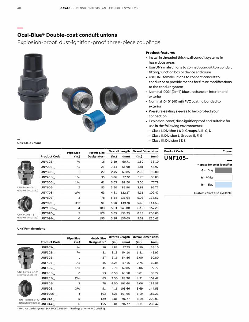
48 O C A L® CO R R OSI O N - R E SIS TA NT CO N D U IT S Y S TEMS
—UNY Male unions
—UNY Female unions
Pipe Size(in.)
Metric Size Designator*
Overall Length Overall Dimensions
Product Code (in.) (mm) (in.) (mm)
UNY105-_ 1 ⁄2 16 2.39 60.71 1.50 38.10
UNY205-_ 3 ⁄4 21 2.44 61.98 1.81 45.97
UNY305-_ 1 27 2.75 69.85 2.00 50.80
UNY405-_ 11 ⁄4 35 3.06 77.72 2.75 69.85
UNY505-_ 11 ⁄2 41 3.63 92.20 3.06 77.72
UNY605-_ 2 53 3.50 88.90 3.81 96.77
UNY705-_ 21 ⁄2 63 4.81 122.17 4.31 109.47
UNY805-_ 3 78 5.34 135.64 5.06 128.52
UNY905-_ 31 ⁄2 91 5.50 139.70 5.69 144.53
UNY1005-_ 4 103 5.63 143.00 6.19 157.23
UNY012-_ 5 129 5.25 133.35 8.19 208.03
UNY014-_ 6 155 5.38 136.65 9.31 236.47
Pipe Size(in.)
Metric Size Designator*
Overall Length Overall Dimensions
Product Code (in.) (mm) (in.) (mm)
UNF105-_ 1 ⁄2 16 1.88 47.75 1.50 38.10
UNF205-_ 3 ⁄4 21 2.13 54.10 1.81 45.97
UNF305-_ 1 27 2.16 54.86 2.00 50.80
UNF405-_ 11 ⁄4 35 2.25 57.15 2.75 69.85
UNF505-_ 11 ⁄2 41 2.75 69.85 3.06 77.72
UNF605-_ 2 53 2.50 63.50 3.81 96.77
UNF705-_ 21 ⁄2 63 3.50 88.90 4.31 109.47
UNF805-_ 3 78 4.00 101.60 5.06 128.52
UNF905-_ 31 ⁄2 91 4.16 105.66 5.69 144.53
UNF1005-_ 4 103 4.25 107.95 6.19 157.23
UNF012-_ 5 129 3.81 96.77 8.19 208.03
UNF014-_ 6 155 3.81 96.77 9.31 236.47* Metric size designator (ANSI C80.1-1994). † Ratings prior to PVC coating.
UNY Male 1⁄2"–4" (shown uncoated)
UNF Female 1⁄2"–4" (shown uncoated)
UNY Male 5"–6" (shown uncoated)
UNF Female 5"–6" (shown uncoated)
Product Code
UNF105- ___ = space for color identifier
G = Gray
W = White
B = Blue
Custom colors also available.
Colour
—Ocal-Blue® Double-coat conduit unionsExplosion-proof, dust-ignition-proof three-piece couplings
Product features• Install in threaded thick-wall conduit systems in
hazardous areas• Use UNY male unions to connect conduit to a conduit
fitting, junction box or device enclosure• Use UNF female unions to connect conduit to
conduit or to provide means for future modifications to the conduit system
• Nominal .002" (2 mil) blue urethane on interior and exterior
• Nominal .040" (40 mil) PVC coating bonded to exterior
• Pressure-sealing sleeves to help protect your connection
• Explosion-proof, dust-ignitionproof and suitable for use in the following environments:†
– Class I, Division 1 & 2, Groups A, B, C, D – Class II, Division 1, Groups E, F, G – Class III, Division 1 & 2

49
—Ocal-Blue® Double-coat GUA series conduit boxesProvides access to wiring, directional changes in conduit and more
GUA series conduit boxes are installed in hazardous areas to protect conductors, act as pull and splice boxes, provide access to conductors for maintenance and future system changes, act as mounting outlets for fixtures (with proper covers) or change conduit direction.
Product features• Grade 60-45-10 ductile iron bodies and cast aluminum
covers (iron covers also available)• Nominal .002" (2 mil) blue urethane coating on both
interior and exterior and nominal .040" (40 mil) PVC coating bonded to exterior
• All hubs have minimum five full threads, integral bushing and pressure-sealing sleeves
• All units furnished with internal grounding screw and ship complete with aluminum cover with O-ring gasket (covers also sold separately for replacement purposes)
• Explosion-proof, dust-ignitionproof and suitable for use in the following environments:†
– Class I, Division 1 & 2, Groups A, B, C, D – Class II, Division 1, Groups E, F, G – Class III, Division 1 & 2
Listings/Certifications†
• UL514A Wet Locations (when used with gasketed covers)
• UL886• CSA C22.2 No. 30
—Ocal-Blue® Double-coat GUA series conduit boxes
Product Code Aluminum Cover Only
Iron Cover Only
Pipe Size(in.)
Metric Size Designator*
Cover Opening
GUA GUAC GUAT GUAX GUAB (in.) (mm)
GUA14-_ GUAC14-_ GUAT14-_ GUAX14-_ GUAB14-_ GUA04-_ GUA04WOD-_ 1 ⁄2 16 2.00 50.80
GUA24-_ GUAC24-_ GUAT24-_ GUAX24-_ GUAB24-_ GUA04-_ GUA04WOD-_ 3 ⁄4 21 2.00 50.80
GUA16-_ GUAC16-_ GUAT16-_ GUAX16-_ GUAB16-_ GUA06-_ GUA06WOD-_ 1 ⁄2 16 3.00 76.20
GUA26-_ GUAC26-_ GUAT26-_ GUAX26-_ GUAB26-_ GUA06-_ GUA06WOD-_ 3 ⁄4 21 3.00 76.20
GUA36-_ GUAC36-_ GUAT36-_ GUAX36-_ GUAB36-_ GUA06-_ GUA06WOD-_ 1 27 3.00 76.20
— — GUAT37-_ GUAX37-_ — GUA07-_ GUA07WOD-_ 1 27 3.63 92.20
GUA47-_ GUAC47-_ GUAT47-_ GUAX47-_ GUAB47-_ GUA07-_ GUA07WOD-_ 11 ⁄4 35 3.63 92.20
— GUAC49-_ GUAT49-_ GUAX49-_ — GUA09-_ GUA09WOD-_ 11 ⁄4 35 5.00 127.00
GUA59-_ GUAC59-_ GUAT59-_ GUAX59-_ GUAB59-_ GUA09-_ GUA09WOD-_ 11 ⁄2 41 5.00 127.00
— GUAC69-_ GUAT69-_ GUAX69-_ GUAB69-_ GUA09-_ GUA09WOD-_ 2 53 5.00 127.00† Ratings prior to PVC coating.
GUA
GUAC
GUAX
GUAT
GUAB
Product Code
GUA14- ___ = space for color identifier
G = Gray
W = White
B = Blue
Custom colors also available.
Colour
O C A L- B LU E® D O U B L E- COAT G UA SER I E S CO N D U IT B OX E S

50 O C A L® CO R R OSI O N - R E SIS TA NT CO N D U IT S Y S TEMS
—Ocal-Blue® Double-coat GUA series conduit boxes (continued)Provides access to wiring, directional changes in conduit and more
—Ocal-Blue® Double-coat GUA series conduit boxes
Product Code Aluminum Cover Only
Iron Cover Only
Pipe Size Metric Size Designator*
Cover Opening
GUA GUAC GUAT GUAX GUAB (in.) (in.) (mm)
GUAD14-_ GUAL14-_ GUAM14-_ GUAN14-_ GUAW14-_ GUA04-_ GUA04WOD-_ 1 ⁄2 16 2.00 50.80
GUAD24-_ GUAL24-_ GUAM24-_ GUAN24-_ GUAW24-_ GUA04-_ GUA04WOD-_ 3 ⁄4 21 2.00 50.80
GUAD16-_ GUAL16-_ GUAM16-_ GUAN16-_ GUAW16-_ GUA06-_ GUA06WOD-_ 1 ⁄2 16 3.00 76.20
GUAD26-_ GUAL26-_ GUAM26-_ GUAN26-_ GUAW26-_ GUA06-_ GUA06WOD-_ 3 ⁄4 21 3.00 76.20
GUAD36-_ GUAL36-_ GUAM36-_ GUAN36-_ — GUA06-_ GUA06WOD-_ 1 27 3.00 76.20
— GUAL47-_ GUAM47-_ GUAN47-_ — GUA07-_ GUA07WOD-_ 11 ⁄4 35 3.63 92.20
GUAD49-_ GUAL49-_ — — — GUA09-_ GUA09WOD-_ 11 ⁄4 35 5.00 127.00
— GUAL59-_ — GUAN59-_ — GUA09-_ GUA09WOD-_ 11 ⁄2 41 5.00 127.00
— GUAL69-_ GUAM69-_ GUAN69-_ — GUA09-_ GUA09WOD-_ 2 53 5.00 127.00† Ratings prior to PVC coating.
GUA
GUAN GUAW
GUADGUAL GUAM
Product Code
GUAD14- ___ = space for color identifier
G = Gray
W = White
B = Blue
Custom colors also available.
Colour

51
—Ocal-Blue® Double-coat external Aluminum hubs with covers and installed green ground screwJunction boxes for branch conduits in hazardous locations
Product features• Accessible wiring chamber provides a convenient
location to maintain or change a system, pull conductors and make splices
• Unique mounting pads and rugged protective housing ideal for installation of OEM devices or instruments
• Die-cast copper-free aluminum alloy A360 construction with precision cast and machined surfaces
• Precision NPT threaded hubs to facilitate trouble-free field installation
• Nominal .002" (2 mil) blue urethane coating on both interior and exterior and nominal .040" (40 mil) PVC coating bonded to exterior
• Explosion-proof, dust-ignition-proof and suitable for use in the following environments:†† – Class I, Division 1 & 2, Groups C, D
– Class II, Division 1, Groups E, F, G – Class III, Division 1 & 2 – NEMA 3, 4, 7 CD, 9 EFG (NEMA 4 rated when – ordered with O-ring installed)
—Ocal-Blue® Double-coat external Aluminum hubs with covers and installed green ground screw
Product Code
Through-Feed W/Surf. Cover
Dead End W/Surf. Cover
L-Style W/Surf. Cover
LB-Style W/Surf. Cover
T-Style W/Surf. Cover
SurfaceCover Only Pipe Size
(in.)
Cover OpeningMetric SizeDesignator*GAC GAE GAL GALB GAT GAS (in.) (mm)
GAC-1-_ † GAE-1-_ † GAL-1-_ † GALB-1-_ † GAT-1-_ † GAS-123-_ • 1 ⁄2 16 3.69 93.73
GAC-2-_ † GAE-2-_ † GAL-2-_ † GALB-2-_ † GAT-2-_ † GAS-123-_ • 3 ⁄4 21 3.69 93.73
GAC-3-_ †• GAE-3-_ †• GAL-3-_ †• GALB-3-_ † GAT-3-_ † GAS-123-_ • 1 27 3.69 93.73
GAC-4-_ †• — GAL-4-_ †• GALB-4-_ † GAT-4-_ † GAS-4-_ • 11 ⁄4 35 3.91 99.31
GAC-5-_ †• — GAL-5-_ †• GALB-5-_ †• GAT-5-_ † GAS-56-_ • 11 ⁄2 41 5.19 131.83
GAC-6-_ †• — GAL-6-_ †• GALB-6-_ †• GAT-6-_ † GAS-56-_ • 2 53 5.19 131.83* Metric size designator (ANSI C80.1-1994). • Made-to-order item. Consult factory for lead time and minimum quantities.† Ratings prior to PVC coating. †† Ratings prior to PVC coating.
GAL
GAT
GALB
GAC GAE
Product Code
GAC-1- ___ = space for color identifier
G = Gray
W = White
B = Blue
Custom colors also available.
Colour
O C A L- B LU E® D O U B L E- COAT E X TER N A L A LU M I N U M H U B S W ITH COV ER S

52 O C A L® CO R R OSI O N - R E SIS TA NT CO N D U IT S Y S TEMS
—Ocal-Blue® Double-coat external Aluminum hubs with covers and installed green ground screw (continued)Junction boxes for branch conduits in hazardous locations
GAD
GAFXGAJU(shown uncoated)
GAX
GAS
—Ocal-Blue® Double-coat external Aluminum hubs with covers and installed green ground screw
Product code
X-Style W/Flange & Surf. Cover
U-Style Surface W/Canopy Cover
X-Style W/Surf. Cover
SurfaceCover Only
Dome Cover Only (Class I, GR. D)
CanopyCover Only Pipe Size
(in.)
Cover OpeningMetric SizeDesignator*GAX GAFX GAJU GAS GAD GAJ (in.) (mm)
GAX-1-_ † GAFX-1-_ † GAJU-1-_ • GALB-1-_ † GAD-123-_ • GAJ-123-_ • 1 ⁄2 16 3.69 93.73
GAX-2-_ † GAFX-2-_ † GAJU-2-_ • GALB-2-_ † GAD-123-_ • GAJ-123-_ • 3 ⁄4 21 3.69 93.73
GAX-3-_ †• GAFX-3-_ † GAJU-3-_ GALB-3-_ † GAD-123-_ • GAJ-123-_ • 1 27 3.69 93.73
GAX-4-_ †• — — GALB-4-_ † — GAJ-4-_ • 11 ⁄4 35 3.91 99.31
GAX-5-_ †• — GAJU-5-_ • GALB-5-_ †• — GAJ-56-_ • 11 ⁄2 41 5.19 131.83
GAX-6-_ †• — GAJU-6-_ GALB-6-_ †• — GAJ-56-_ • 2 53 5.19 131.83* Metric size designator (ANSI C80.1-1994). • Made-to-order item. Consult factory for lead time and minimum quantities.† Ratings prior to PVC coating. †† Ratings prior to PVC coating.
GAJ
Product Code
GAX-1 ___ = space for color identifier
G = Gray
W = White
B = Blue
Custom colors also available.
Colour
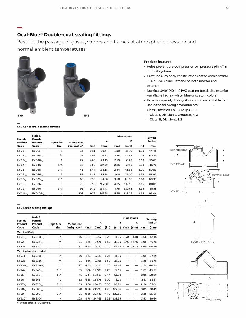
53
—Ocal-Blue® Double-coat sealing fittingsRestrict the passage of gases, vapors and flames at atmospheric pressure and normal ambient temperatures
Product features• Helps prevent pre-compression or “pressure piling” in
conduit systems• Gray iron alloy body construction coated with nominal
.002" (2 mil) blue urethane on both interior and exterior
• Nominal .040" (40 mil) PVC coating bonded to exterior – available in gray, white, blue or custom colors
• Explosion-proof, dust-ignition-proof and suitable for use in the following environments:† – Class I, Division 1 & 2, Groups C, D
– Class II, Division 1, Groups E, F, G – Class III, Division 1 & 2
EYD EYS
Male & Female Product Code
Female Product Code
Pipe Size (in.)
Dimensions TurningRadiusMetric Size
Designator*
A B
(in.) (mm) (in.) (mm) (in.) (mm)
EYD1-_ EYD16-_ 1 ⁄2 16 3.81 96.77 1.50 38.10 1.75 44.45
EYD2-_ EYD26-_ 3 ⁄4 21 4.08 103.63 1.75 44.45 1.98 50.29
EYD3-_ EYD36-_ 1 27 4.85 123.19 2.19 55.63 2.19 55.63
EYD4-_ EYD46-_ 11 ⁄4 35 5.00 127.00 2.25 57.15 1.80 45.72
EYD5-_ EYD56-_ 11 ⁄2 41 5.44 138.18 2.44 61.98 2.00 50.80
EYD6-_ EYD66-_ 2 53 6.25 158.75 3.00 76.20 2.32 58.93
EYD7-_ EYD76-_ 21 ⁄2 63 7.50 190.50 3.50 88.90 2.69 68.33
EYD8-_ EYD86-_ 3 78 8.50 215.90 4.25 107.95 3.15 80.01
EYD9-_ EYD96-_ 31 ⁄2 91 9.19 233.43 4.75 120.65 3.38 85.85
EYD10-_ EYD106-_ 4 103 9.75 247.65 5.25 133.35 3.64 92.46
Male & Female Product Code
Female Product Code
Pipe Size (in.)
Dimensions TurningRadiusMetric Size
Designator*
A B C
(in.) (mm) (in.) (mm) (in.) (mm) (in.) (mm)
Vertical Only
EYS1-_ EYS116-_ 1 ⁄2 16 3.31 84.07 1.25 31.75 1.50 38.10 1.66 42.16
EYS2-_ EYS26-_ 3 ⁄4 21 3.65 92.71 1.50 38.10 1.75 44.45 1.96 49.78
EYS3-_ EYS36-_ 1 27 4.25 107.95 1.75 44.45 2.19 55.63 2.40 60.96
Vertical or Horizontal
EYS11-_ EYS116-_ 1 ⁄2 16 3.63 92.20 1.25 31.75 — — 1.09 27.69
EYS21-_ EYS216-_ 3 ⁄4 21 3.66 92.96 1.50 38.10 — — 1.25 31.75
EYS31-_ EYS316-_ 1 27 4.25 107.95 1.75 44.45 — — 1.59 40.39
EYS4-_ EYS46-_ 11 ⁄4 35 5.00 127.00 2.25 57.15 — — 1.81 45.97
EYS5-_ EYS56-_ 11 ⁄2 41 5.44 138.18 2.44 61.98 — — 2.00 50.80
EYS6-_ EYS66-_ 2 53 6.25 158.75 3.00 76.20 — — 2.31 58.67
EYS7-_ EYS76-_ 21 ⁄2 63 7.50 190.50 3.50 88.90 — — 2.56 65.02
EYS8-_ EYS86-_ 3 78 8.50 215.90 4.25 107.95 — — 3.09 78.49
EYS9-_ EYS96-_ 31 ⁄2 91 9.19 233.43 4.75 120.65 — — 3.38 85.85
EYS10-_ EYS106-_ 4 103 9.75 247.65 5.25 133.35 — — 3.53 89.66† Ratings prior to PVC coating.
—EYD Series drain sealing fittings
—EYS Series sealing fittings
EYD 1⁄2" – 1"
A
B
Turning Radius
EYD 11⁄4" – 4"
A
Turning Radius
EYS1 – EYS5
EYS11 – EYS101-TB
A
CB
O C A L- B LU E® D O U B L E- COAT SE A L I N G FIT TI N G S
B
A

54 O C A L® CO R R OSI O N - R E SIS TA NT CO N D U IT S Y S TEMS
EZS EZD
—Ocal-Blue® Double-coat sealing fittings (continued)Restrict the passage of gases, vapors and flames at atmospheric pressure and normal
ambient temperatures
—Chico® Sealing compound and fiberEnsures proper functioning of EYS sealing fittings.
—EZS Series sealing fittings
—Chico® Sealing compound and fiber
—EZD Series sealing fittings
Ocal-Blue® Double-Coat EYS Sealing Fittings require fiber filler and sealing compound to function properly. Use Chico® X Fiber Filler to form a dam around the sealing fitting’s integral bushing, as well as at the end of the conduit and around conductors entering the hub. Chico® A Sealing Compound expands slightly while hardening and bonds to the inner walls of the sealing fitting.
Product features• Sealing compound mixes with water, pours easily
and hardens in 60–70 minutes• Fiber filler mineral wool holds sealing compound in place while it hardens
SEAL-A3 EZD
Female Product Code
Male & Female Product Code
Pipe Size(in.)
Metric Size Designator*
EZS1-_ EZS16-_ 1 ⁄2 16
EZS2-_ EZS26-_ 3 ⁄4 21
EZS3-_ EZS36-_ 1 27
EZS4-_ EZS46-_ 11 ⁄4 35
EZS5-_ EZS56-_ 11 ⁄2 41
EZS6-_ EZS66-_ 2 53
EZS7-_ EZS76-_ 21 ⁄2 63
EZS8-_ EZS86-_ 3 78
* Metric size designator (ANSI C80.1-1994).† Ratings prior to PVC coating.
Product Code
Pipe Size(in.)
Metric Size Designator*
EZD111-_ 1 ⁄2 16
EZD211-_ 3⁄4 3 ⁄4 21
EZD311-_ 1 27
EZD411-_ 11 ⁄4 35
EZD511-_ 11 ⁄2 41
EZD611-_ 2 53
* Metric size designator (ANSI C80.1-1994).
EZDWith inspection cover off
Product Code Description
SEAL-A3 Chico® A Sealing Compound, 1 lb. net wt./23 cu.in. vol.
FIBER-X6 Chico® X Fiber Filler, 8 oz.
SEALKIT-A4 Chico® A Sealing Compound, 1 lb. net wt./23 cu.in. vol., with 1 oz. Chico® X Fiber Filler
Chico® is a registered trademark of Cooper Crouse-Hinds.
Product Code
EZS1- ___ = space for color identifier
G = Gray
W = White
B = Blue
Custom colors also available.
Colour

55
A12A
—Ocal® PVC-coated steel strutRugged steel channels protected by corrosion-resistant PVC
Product features• Electro-galvanized zinc plated• Nominal .007 - .015" (7 - 15 mil) PVC coating• PVC coating available in your choice of blue, white
or gray standard colors• Custom colors also available on request• Sold in 10-ft. (3.048m) lengths with standard
length tolerance of ± 1 ⁄8" (3.18mm)• Choose between standard 15 ⁄8" (41.28mm) and
shallow 13 ⁄16" (20.64mm) depths• Available in both solid and punched styles• Not recommended for vertical applications
Product Code
Steel Thickness Width x Height
Style Gauge (mm) (in.) (mm)
A12-_ Standard 12 2.65 1.63 x 1.63 41.28 x 41.28
A12A-_ Back to Back 12 2.65 1.63 x 3.25 41.28 x 82.55
A12P-_ Standard Punched 12 2.65 1.63 x 1.63 41.28 x 41.28
C14-_ Shallow 14 1.89 1.63 x .81 41.28 x 20.64
C14P-_ Shallow Punched 14 1.89 1.63 x .81 41.28 x 20.64
—Ocal® PVC-coated steel strut
C14
15⁄87⁄8
9⁄32
13⁄16
15⁄8
15⁄8
7⁄89⁄32
3⁄8
A12
Product Code
EZS1- ___ = space for color identifier
G = Gray
W = White
B = Blue
Custom colors also available.
Product Code
A12- ___ = space for color identifier
G = Gray
W = White
B = Blue
Custom colors also available.
Colour
O C A L- P VC- COATED S TEEL S TR U T
A12
A12P

56 O C A L® CO R R OSI O N - R E SIS TA NT CO N D U IT S Y S TEMS
—Stainless steel strut
Type 304 StainlessProduct Code
Type 316 StainlessProduct Code
Steel Thickness Length Width x Height
Style Gauge (mm) (ft.) (m) (in.) (in.) (mm)
A1200 10SS A120010T316SS Standard 12 2.65 10 3.05 1.63 x 1.63 41.28 x 41.28
A1200 20SS A120020T316SS Standard 12 2.65 20 6.10 1.63 x 1.63 41.28 x 41.28
A1200HS 10SS A1200HS10T316SS Standard Half-Slot 12 2.65 10 3.05 1.63 x 1.63 41.28 x 41.28
A1200HS 20SS A1200HS20T316SS Standard Half-Slot 12 2.65 20 6.10 1.63 x 1.63 41.28 x 41.28
B1400 10SS B140010T316SS Shallow 14 1.89 10 3.05 1.63 x .81 41.28 x 22.23
B1400 20SS B140020T316SS Shallow 14 1.89 20 6.10 1.63 x .81 41.28 x 22.23
A1202HS10SS A1202HS10T316SS Back-to-Back Half-Slot 12 2.65 10 3.05 1.63 x 3.25 41.28 x 82.55
A1202HS20SS A1202HS20T316SS Back-to-Back Half-Slot 12 2.65 20 6.10 1.63 x 3.25 41.28 x 82.55
A1202
7⁄8"
Half-Slot
1 5⁄8"7⁄8"
13⁄16"
B1400
1 5⁄8"
1 5⁄8"
7⁄8"
A1200
—Stainless steel strutType 304 or Type 316 stainless – cold-roll formed for strength
Product features• 12- or 14-gauge Type 304 or Type 316 stainless
steel• Available in 10-ft. (3.048m) and 20-ft. (6.096m)
lengths with standard length tolerance of ± 1 ⁄8" (3.18mm)
• Choose standard or shallow and solid or half-slot style

57
—Stainless steel hardware accessories
AB203
AB214
4 Holes 3⁄4" Dia.
3 1⁄2"
6"
41⁄4"
3 5⁄16"
AP235SQ
41⁄4"
6"
AB201
AB219
45˚ 3"
2 5⁄16"
11⁄16"
SPAB227
5 5⁄8"
3 1⁄2"
AB220
3 5⁄8"
AB206
45˚
2 1⁄2"
3 1⁄2"
AB225
AB213
9 5⁄32"
3 7⁄8"
1 5⁄8"
3 3⁄4"
1 21⁄32"AW219
Type 304 Stainless Product Code
Type 316 StainlessProduct Code
Size (in.)
Spring Nut – Regular
— A100 1/4 SS 1 ⁄4
— A100 5/16SS 5 ⁄16
— A100 3/8 SS 3 ⁄8
Spring Nut – Short
— B100 1/4 SS 1 ⁄4
— B100 3/8 SS 3 ⁄8
— B100 1/2ss 1 ⁄2
Springless Nut
— AB100 1/4 SS 1 ⁄4
— AB100 5/16SS 5 ⁄16
— AB100 3/8 SS 3 ⁄8
Hex Head Cap Screw
E142 (T) X (L) SS E142 (T) X (L) SS316 —
Hex Nut
E145 1/4 SS — 1 ⁄4
E145 5/16SS — 5 ⁄16
E145 3/8 SS — 3 ⁄8
E145 1/2 SS — 1 ⁄2
Fender Washer
EF147 1/4 SS — 1 ⁄4
EF147 3/8 SS — 3 ⁄8
EF147 1/2ss — 1 ⁄2
Square Washer
AB241 1/4SS AB241-1/4SS316 1 ⁄4
AB241 5/16SS — 5 ⁄16
AB241 3/8 SS AB241-3/8 SS316 3 ⁄8
AB241 1/2SS AB241-1/2SS316 1 ⁄2
Rod Coupling
H119 1/4SS — 1 ⁄4
H119 3/8SS — 3 ⁄8
H119 1/2SS H119-1/2SS6 1 ⁄2
U-Bolt Beam Clamps
U501SS — 33 ⁄16H
U502ss — 313 ⁄16H
EF147Fender Washer
E145Hex Nut
AB241Square Washer
E142Hex Head Cap Screw H119
Rod Coupling
S TA IN L E SS S TEEL H A R DWA R E ACCE SSO R I E S
Type 304 Stainless Product Code
Type 316 StainlessProduct code
Size (in.)
Flat Plate Fittings
AB220SS AB220SS316 55 ⁄8 x 31 ⁄2
AB207SS AB207SS6C 53 ⁄8
X207SS X207SS6C 71 ⁄4
AB206SS AB206SS6C 35 ⁄8
90° Corner Fittings or Brackets
AB201SS AB201SS316 —
AB202SS AB202SS316 15 ⁄8 x 2
AB203SS AB203SS316 —
AB204SS AB204SS316 21 ⁄4 x 35 ⁄8
AB213SS AB213SS316 —
AB214SS AB214SS316 —
AB219SS AB219SS316 —
AW219SS AW219SS316 95 ⁄32 x 37⁄8
AB205SS AB205SS316 —
45° Fittings
AB225SS AB225SS316 31 ⁄2 x 21 ⁄2
SPAB227SS AB227SS316 3 x 25 ⁄16
Pedestal Base
AP232SS AP232SS6 41 ⁄4 x 31 ⁄2
AP232SQSS AP232SQSS6 41 ⁄4 x 31 ⁄2
AP235SS AP235SS6 6 x 4
AP235SQSS AP235SQSS6 6 x 4

58 O C A L® CO R R OSI O N - R E SIS TA NT CO N D U IT S Y S TEMS
PVC-coated all-thread rod
Stainless Steel all-thread rod
Type 304 StainlessProduct Code
Type 316 StainlessProduct Code
Trade Size Length
(in.) (mm) (ft.) (mm)
H104-3/8X6SS H104 3/8X6SS316 3 ⁄8 9.53 6.00 1.83
H104 3/8X12SS H104-3/8X12SS6 3 ⁄8 9.53 12.00 3.66
H104-1/2X6SSC H104-1/2X6SS6 1 ⁄2 12.70 6.00 1.83
H104 1/2X12SS H104 1/2X12SS316 1 ⁄2 12.70 12.00 3.66
Trade Size Length
Product Code (in.) (mm) (ft.) (mm)
THR1/4X10-_ 1 ⁄4 6.35 10.00 3.05
THR3/8X3-_ 3 ⁄8 9.53 3.00 0.91
THR3/8X6-_ 3 ⁄8 9.53 6.00 1.83
THR3/8X10-_ 3 ⁄8 9.53 10.00 3.05
THR1/2X3-_ 1 ⁄2 12.70 3.00 0.91
THR1/2X6-_ 1 ⁄2 12.70 6.00 1.83
THR1/2X10-_ 1 ⁄2 12.70 10.00 3.05
Product Code
Base “A” Base “B” Jaw Opening Tapped Hole Load Rating‡
(in.) (mm) (in.) (mm) (in.) (mm) (in.) (mm) (lbs.) (kg)
500-_ 1 25.40 11 ⁄4 31.75 15 ⁄16 23.81 1 ⁄4 -20 6.35 - 20 450 204.12
501-_ 11 ⁄2 38.10 15 ⁄8 41.28 7⁄8 22.23 15 ⁄16 -18 7.94 - 18 800 362.87
502-_ 2 50.80 2 50.80 1 25.40 3 ⁄8-16 9.53 - 16 1300 589.67
503-_ 25 ⁄8 66.68 21 ⁄2 63.50 1 25.40 1 ⁄2-13 12.70 - 13 1300 589.67
508-_ 21 ⁄2 63.50 23 ⁄8 60.33 21 ⁄8 53.98 1 ⁄2-13 12.70 - 13 1700 771.11
—Stainless steel all-thread rod
—Ocal® PVC-coated steel all-thread rod
Product Code Diameter x Length
THR 3/8 x 3- ___ = space for color identifier
G = Gray
W = White
B = Blue
Custom colors also available.
Colour
—All-thread rodContinuously threaded rod for use with conduit hangers and strut to suspend overhead conduit runs
Product features• All-thread steel rod coated with Nominal .007 -
.015" (7 - 15 mil) PVC in blue, white or gray with custom colors available on request
• Available in 1 ⁄4", 3 ⁄8" or 1 ⁄2" standard diameters and in 3-, 6- or 10-ft. standard lengths
• Also available uncoated in Type 304 or Type 316 stainless steel
• Stainless steel all-thread rod comes in 3 ⁄8" or 1 ⁄2" diameters in 6-ft. standard lengths with other diameters and lengths available on request

59
—Ocal® PVC-coated hanger rod beam clampsCorrosion-protected clamps for hanging threaded rod
Product features• Malleable iron construction• Nominal .007 - .015" (7 - 15 mil) PVC coating in blue,
white, gray or custom colors• 500, 502 and 503 also available uncoated in Type 316
stainless steel; add -SS316 to catalog number to order (for example: 502-SS316)
Product features• Nominal .007 - .015" (7 - 15 mil) PVC coating in blue,
white, gray or custom colors• Rated for loads of up to 500 lbs. (226.80kg) with a
safety factor of three
Type 304 StainlessProduct Code
Type 316 StainlessProduct Code
Trade Size Length
(in.) (mm) (ft.) (mm)
H104-3/8X6SS H104 3/8X6SS316 3 ⁄8 9.53 6.00 1.83
H104 3/8X12SS H104-3/8X12SS6 3 ⁄8 9.53 12.00 3.66
H104-1/2X6SSC H104-1/2X6SS6 1 ⁄2 12.70 6.00 1.83
H104 1/2X12SS H104 1/2X12SS316 1 ⁄2 12.70 12.00 3.66
Product Code
Base “A” Base “B” Jaw Opening Tapped Hole Load Rating‡
(in.) (mm) (in.) (mm) (in.) (mm) (in.) (mm) (lbs.) (kg)
500-_ 1 25.40 11 ⁄4 31.75 15 ⁄16 23.81 1 ⁄4 -20 6.35 - 20 450 204.12
501-_ 11 ⁄2 38.10 15 ⁄8 41.28 7⁄8 22.23 15 ⁄16 -18 7.94 - 18 800 362.87
502-_ 2 50.80 2 50.80 1 25.40 3 ⁄8-16 9.53 - 16 1300 589.67
503-_ 25 ⁄8 66.68 21 ⁄2 63.50 1 25.40 1 ⁄2-13 12.70 - 13 1300 589.67
508-_ 21 ⁄2 63.50 23 ⁄8 60.33 21 ⁄8 53.98 1 ⁄2-13 12.70 - 13 1700 771.11
—Ocal® PVC-coated hanger rod beam clamps
500-G Hanger Rod Beam Clamp
MINE3/4-G Mini Conduit Hanger
A B
Product Code
Pipe Size(in.)
Metric Size Designator*
MINE1/2-_ 1 ⁄2 16
MINE3/4-_ 3 ⁄4 21
MINE1-_ 1 27
MINE1-1/4-_ 11 ⁄4 35
MINE1-1/2-_ 11 ⁄2 41
* Metric size designator (ANSI C80.1-1994).
Product Code
Pipe Size(in.)
Metric Size Designator*
MINE2-_ 2 53
MINE2-1/2-_ 21 ⁄2 63
MINE3-_ 3 78
MINE3-1/2-_ 31 ⁄2 91
MINE4-_ 4 103
—Ocal® PVC-coated mini conduit hangers
* Metric size designator (ANSI C80.1-1994).‡ Load ratings based on bottom hole of beam clamp with safety factor of three.CSA File No. LR-52208
Product Code
500- ___ = space for color identifier
G = Gray
W = White
B = Blue
Custom colors also available.
Colour
Product Code
MINE1- ___ = space for color identifier
G = Gray
W = White
B = Blue
Custom colors also available.
Colour
O C A L® P VC- COATED H A N G ER R O D B E A M CL A M P S
—Ocal® PVC-coated mini conduit hangersIncludes stainless steel bolt and nut for fast, easy installation

60 O C A L® CO R R OSI O N - R E SIS TA NT CO N D U IT S Y S TEMS
Stainless steel Cobra® clamp PVC-coated pipe strap
Ocal®PVC-Coated Strut Pipe Straps
Pipe Size(in.)
Metric Size Designator*
SS1/2-_ 1 ⁄2 16
SS3/4-_ 3 ⁄4 21
SS1-_ 1 27
SS1-1/4-_ 11 ⁄4 35
SS1-1/2-_ 11 ⁄2 41
SS2-_ 2 53
SS2-1/2-_ 21 ⁄2 63
SS3-_ 3 78
SS3-1/2-_ 31 ⁄2 91
SS4-_ 4 103
SS5-_ 5 129
* Metric size designator (ANSI C80.1-1994).
Type 316 Stainless Product Code
Pipe Size(in.)
Metric Size Designator*
CPC075SS6 1 ⁄2 16
CPC100SS6 3 ⁄4 21
CPC100SS6 1 27
CPC150SS6 11 ⁄4 35
CPC150SS6 11 ⁄2 41
CPC200SS6 2 53
CPC250SS6 21 ⁄2 63
CPC100SS6 3 78
CPC350SST 31 ⁄2 91
CPC400SS6 4 103
* Metric size designator (ANSI C80.1-1994).Note: Stainless steel strut straps are recommendedonly for use with stainless steel strut. Stainless steel straps may damage the PVC coating on PVCcoatedstrut.
—Stainless steel Cobra® clamp – Type 316
—Ocal® PVC-coated strut pipe straps
Size Design Load
Product Code Material (in.) (mm) (lbs.) (kg)
H122-1/4-SS6 Type 316 Stainless Steel 1 ⁄4 6.35 150.00 68.04
H122-3/8-SS6 Type 316 Stainless Steel 3 ⁄8 9.53 590.00 267.62
H122-1/2-SS6 Type 316 Stainless Steel 1 ⁄2 12.70 1080.00 489.88
Product Code
SS-1 ___ = space for color identifier
G = Gray
W = White
B = Blue
Custom colors also available.
Colour
Just twist-insert these pipe straps anywhere you need them along the slot side of a channel. For additional flexibility, you can position the straps as closely as your pipe couplings permit.
Product features• Combination slot and hex head bolt for flexibility of
attachment• Captivated square nut on shoulder enables easy
one-handed tightening• Use with either 15 ⁄8" or 11 ⁄2" strut for greater
versatility• Shipped pre-assembled for easier counting,
sorting and handling• Available with Nominal .007 - .015" (7 - 15 mil) PVC
coating in your choice of blue, white or gray standard colors (custom colors also available on request)
• Or choose uncoated Cobra® Clamps in Type 316 stainless steel
—Pipe straps for strutDesigned for easy attachment of conduit to strut

61
—Trapnut® strut fastenerFewer parts, less installation time and huge labor savings
The unique scissor action of the Trapnut® Strut Fastener closes at any desired position on the threaded rod. Once closed, precision threads trap the rod for a sturdy hold that can be adjusted up or down for fine-tune positioning. While the versatile Trapnut® Fastener has a locking pin that holds it in the desired position, it can also be removed and reused.
Unlike a hex nut, there’s no need to thread the Trapnut® Fastener from either end of the rod, saving valuable time on the job. While the Trapnut® Fastener is a time-saver for new work, it’s invaluable for retrofit applications. Rather than disassembling an existing trapeze to run additional conduit above it, simply clamp the Trapnut® Fastener between the trapeze and beam clamp for a speedy retrofit solution. Ideal for applications where the rod ends aren’t accessible.
The Trapnut® Fastener offers sturdy, loadbearingsteel construction for a solid installation. Inaddition, the Trapnut® Fastener functions as a hexnut, square washer and flat washer all in one, sothere are fewer parts to keep track of on the job.
• Takes 30% less time than the traditional method on new work*
• Takes 43% less time than the traditional method on retrofit applications*
* Based on time study conducted by ABB comparing the time to install 15 feet of 2" conduit with typical trapeze assemblies using washers and nuts versus Trapnut® fasteners.
—01 Hold in the open position• No need to thread the Trapnut®Fastener from either end of the rod – saves valuable time• Perfect for retrofit applications where the rod ends are not accessible—02 Insert the bottom plate on the rod and close the top plate. • Precision threads trap the threaded rod for a sturdy hold that can be adjusted up or down for fine-tune positioning• Functions as a hex nut, square washer and flat washer combined—03 Press the pin with pliers• Locking pin holds Trapnut® Fastener in the desired position • Can be removed and reused—04 Tighten to the desired position with pliers• Can be adjusted up or down for fine-tune positioning • Sturdy, load-bearing stainless steel construction• Sized to provide custom fit for either 15 ⁄8" or 11 ⁄2" strut systems
—01
—02
—03
—04
Size Design Load
Product Code Material (in.) (mm) (lbs.) (kg)
H122-1/4-SS6 Type 316 Stainless Steel 1 ⁄4 6.35 150.00 68.04
H122-3/8-SS6 Type 316 Stainless Steel 3 ⁄8 9.53 590.00 267.62
H122-1/2-SS6 Type 316 Stainless Steel 1 ⁄2 12.70 1080.00 489.88
—Type 316 stainless steel Trapnut® fastener
TR A PN U T ® S TR U T FA S TEN ER

62 O C A L® CO R R OSI O N - R E SIS TA NT CO N D U IT S Y S TEMS
ABB Ocal® PVC-Coated Conduit is designed to help prevent corrosion from striking weak points in conduit systems. But any PVC-coated conduit system is only as good as the installation job. The wrong tools can result in incorrectly installed pipes and fittings or damage to PVC coating, creating those weak points wherecorrosion starts.
After careful research and evaluation, ABB now offers you the very best installation tools available for PVC-coated conduit. These tools are ready for use on PVC-coated conduit right out of the box. What that means to the installer, is lower costs – in equipment, in installation time and in time normally spent adapting standard tools for use on PVC-coated conduit.
Hassle-Free InstallationCount on ABB to provide a hassle-free means for installers to get the right tools for the job in their hands – just another benefit of using Ocal® products.
For more information on Ocal® InstallationGuidelines, see pages 80-86.
—Ocal® Installation ProductsThe right tools for the job

63
—GREENLEE® Model 555 electric bender for PVC-coated conduitBends 1 ⁄2" through 2" PVC-coated conduit
—Hand bender for PVC-coated conduitMake saddles, offsets and conventional bends
When using this electric bending machine on 1 ⁄2" through 2" conduit, the shoes as well as the rollerassembly should be of the type designed specifically for use with PVC-coated conduit.
When using conventional shoes, the shoes and each of the rollers in the roller assembly must be machined 60 thousandths. Some manufacturers use slide bars instead of a roller assembly, and these, too, must be machined 60 thousandths.
Be sure to compensate for “spring back," since PVC coating often requires the setting to be off as much as 5°.
Product Code Description
GBENDER GREENLEE® Model 555 Bender
Shoes and roller kit for 40-mil PVC-coated conduit
12586 1 ⁄2" – 2" Shoes and Roller Supports
Product Code Conduit Size (in.)
35220 1 ⁄2
35225 3 ⁄4
2424A8 1
—GREENLEE® Model 555 electric bender for PVC-coated conduit
—Hand bender for PVC-coated conduit
O C A L® I NS TA L L ATI O N PR O D U C TS

64 O C A L® CO R R OSI O N - R E SIS TA NT CO N D U IT S Y S TEMS
—Ridgid stationary power threading machine1224 Series
• The standard jaw inserts for these units are intended to secure uncoated rigid conduit. The teeth of the stan-dard jaw inserts will penetrate the PVC coating, but not bite into the steel. As a result, the standard jaw inserts will grind the PVC coating off the conduit. To prevent this, shell style clamps or jaw inserts for coated conduit may be used.
• Shell Clamps – Range: 1/2" to 31/2" To properly clamp the conduit, the shell style clamps described earlier can be used on conduit sizes from 1/2" to 1/2" However, for 4" conduit, there is not enough room in the chuck to accommodate both the 4 in. con-duit and shell clamps.
• Jaw inserts for coated conduit – Range: 1/2" to 4" The jaw inserts for coated conduit have a wider surface area to effectively grip the PVC coating. Ridgid Cata-logue No. 26247 is the jaw insert for coated conduit used in the Ridgid 1224 threading machine.
There is no need to pencil cut or score the PVC because these threading machines use a roller cutter to remove 1/4 in. of the PVC coating. Cuttings simply fall onto the screen on the lower portion of the machine.
Stationary power threading machines such as the Ridgid model number 1224 have the capacity to thread rigid conduit from 1/2" to 4".
—01 Special jaw insert for PVC coated conduit Ridgid model number 97365 and 26247—02 Standard jaw insert—03 In hot weather, use scored shell clamps to prevent slipping
—01
—02
—03

65O C A L® I NS TA L L ATI O N PR O D U C TS
HandheldThe Ridgid #12R is typically used for smaller size conduit. The ratchet knob indicates forward and reverse. Die heads snap in from both sides and lock in place. (#12R includes ratchet and handle only)
Handheld poweredThe Ridgid 700 Power Drive is a heavy duty handheld tool typically used for conduit up to 2 inches in diameter. The 700 Power Drive is designed for Ridgid 12R dies, available in both 115V and 230V models. Optional case is available for this tool.
—Ridged 700 portable threader and die headsFor PVC coated conduit
Product Code Description
Ridgid 700 portable threader and die heads for PVC coated conduit
51857 High speed 1/2" 12R die head for coated conduit
51862 High speed 3/4" 12R die head for coated conduit
51867 High speed 1" 12R die head for coated conduit
51872 High speed 11/4" 12R die head for coated conduit
51877 High speed 11/2" 12R die head for coated conduit
51882 High speed 2" 12R die head for coated conduit
—Ridged 700 portable threader
Product features• Sturdy, stable frame collapses for easy mobility
and storage• Ceiling brace for overhead support enables you
to secure frame even during difficult work• Features recesses for bending tubes 3 ⁄8", 1 ⁄2" and
3 ⁄4" O.D.
—Ridgid Tools 460-6Tri-stand Chain vise
Pipe Capacity
Product Code Description in.) Metric Size Designator*
Ridgid Tools 460-6 Tri-Stand with 6" Chain Vise (use with Ocal® Half-Shell Clamps) 1/2 – 6 16 – 155* Metric size designator (ANSI C80.1-1994).
—Ridgid Tools 460-6
51862

66 O C A L® CO R R OSI O N - R E SIS TA NT CO N D U IT S Y S TEMS
Conduit Size
Product Code (in.) Metric
Individual Half-Shell Clamps
HLF-SHL-CLP1/2 1 ⁄2 16
HLF-SHL-CLP3/4 3 ⁄4 21
HLF-SHL-CLP1 1 27
HLF-SHL-CLP1-1/4 11 ⁄4 35
HLF-SHL-CLP1-1/2 11 ⁄2 41
HLF-SHL-CLP2 2 53
HLF-SHL-CLP2-1/2 21 ⁄2 63
HLF-SHL-CLP3 3 78
HLF-SHL-CLP3-1/2 31 ⁄2 91
HLF-SHL-CLP4 4 103
Half-Shell Clamp Set (in carrying/storage case)
HLF-SHL-CLP-SET1 1 ⁄2 -2 78* Metric size designator (ANSI C80.1-1994).
—Aluminum pipe wrenches
Avoid the expense of purchasing a yoke vise with special jaws – or the trouble of making clamps out of PVC or steel pipe – to cut and thread PVC-coated conduit. These Half-Shell Clamps come in the full range of 1 ⁄2" to 6" trade sizes. Buy individual sizes, or choose our convenient set, which contains all the sizes from 1 ⁄2" to 2" in a handy carrying/storage case.
A unique internal design ensures secure clamping while protecting the integrity of the conduit’s PVC coating. Cast from ductile iron for extreme strength and durability, Ocal® Half-Shell Clamps offer years of consistent, reliable service.
Product features• Two-piece construction, cast from ductile iron for
exceptional strength, durability and performance• Cross-hatched interior surface grips conduit
securely while safeguarding PVC jacket from damage
• Available individually in 1 ⁄2" through 4" trade sizes• Also available in a convenient set – 1 ⁄2" to 2" trade
sizes• Each clamp clearly marked with trade size for easy
identification• Openings at each end enable hanging for handy
storage
—Ocal® Half-shell clampsSuperior design and construction for faster, safer chain-vise clamping of PVC-coated conduit.

67O C A L® I NS TA L L ATI O N PR O D U C TS
Product features• Replaces the standard jaw inserts in a yoke vise• Provides greater clamping force and prevents pipe
from spinning during threading• Machined aluminum construction• Three-piece set
Product features• Easy pressure control transmits optimum force
onto tube• Hardened, high-alloy steel cutter wheel provides
long service life and burr-free external cutting
—Steel pipe cuttersSpecially designed for cutting PVC-coated conduit
Weight
Product Code Description (lbs.) (kg)
JAWS23 Use with RIDGID No. 23 and 40A Yoke Vises 2.80 1.27
Product Code Description Pipe O.D.
P70045C Steel Pipe Cutter – Up to 2" 1 ⁄8"–2"
P70060C Steel Pipe Cutter – Up to 4" 1 ⁄8"–4"
—Ocal® Jaws for PVC-coated conduit
—Ocal® Jaws for PVC-coated conduit
—Ocal® Jaws for PVC-coated conduitDesigned to hold PVC-coated conduit securely in a yoke-style vise without damagingthe conduit

68 O C A L® CO R R OSI O N - R E SIS TA NT CO N D U IT S Y S TEMS
Product features• Smooth-running ratchet• Tempered-steel cutting bit• For steel tubes 1 ⁄4" to 2" O.D.
Use with our pliers, or purchase the jaws only and adapt your own!
—Ratchet pipe reamerRapid and clean deburring
—Ocal® J-wrenchesRemovable aluminum jaws for PVC-coated conduit
Product Code Description Pipe O.D. (in.)
70289 Ratchet Pipe Reamer 1 ⁄4–2
—Ratchet pipe reamer
—Ratchet pipe reamer
J442
J460
J42 J60
Product Code Description Pipe Capacity (in.)
J442 12" J-Wrench with Jaws 1 ⁄2 – 11 ⁄4
J460 16" J-Wrench with Jaws 11 ⁄2 – 21 ⁄2
J42 12" Jaw Set only 1 ⁄2 – 11 ⁄4
J60 16" Jaw Set only 11 ⁄2 – 21 ⁄2

69O C A L® I NS TA L L ATI O N PR O D U C TS
—Strap wrenchesSpecially coated strap won’t absorb oil
Handle Length Strap Length Strap Width Pipe Capacity Pipe Capacity (O.D.) Weight
Product Code (in.) (mm) (in.) (mm) (in.) (mm) (in.) (mm) (in.) (mm) (lbs.) (kg)
31355 11.75 298.45 17.00 431.80 1.75 44.45 2.00 50.80 3.50 88.90 1.75 .79
31370 18.00 457.20 29.25 742.95 1.75 44.45 5.00 127.00 5.50 139.70 2.75 1.25
—Strap wrenches
3137031355

70 O C A L® CO R R OSI O N - R E SIS TA NT CO N D U IT S Y S TEMS
Product features• Meets NEC® requirements for protection against
corrosion: “Where corrosion protection is necessary and the conduit is threaded in the field, all threads shall be coated with an approved electrically conductive, corrosion-resistant compound.”
• Extremely adhesive compound flows smoothly into uneven contours and voids, ensuring easy application and complete, positive protection and lubrication
• Won’t settle out, thin, thicken, harden or dry out under the most severe environmental conditions
• Excellent temperature characteristics — can be brushed on at -50° F to 250° F (-45° C to 121° C) and remains intact for short periods even at 1,800° F (982° C)
• Helps ensure low resistance and seals out air and moisture
• Unique, homogenized blend of pure, polished colloidal copper, rust and corrosion inhibitors
NEC and National Electrical Code are registered trademarks of the National Fire Protection Association, Inc.
—KOPR-SHIELD® Joint compoundProtects, lubricates and enhances the conductivity of all electrical connections
Product Code Container Size
201-31879 Brush Cap Can 11 ⁄2 oz. (.04 liter)
201-31879-1 Brush Cap Can 4 oz. (.12 liter)
CP8-TB Brush Cap Can 8 oz. (.24 liter)
CP16 Brush Cap Can 1 pint (.47 liter)
CP128 Can 1 gallon (3.79 liter)
Note: Not recommended for food & beverage processing applications.
—KOPR-SHIELD® Joint compound

71O C A L® I NS TA L L ATI O N PR O D U C TS
—Ocal® Touch-up compoundsFast-drying, air-cure patch for Ocal® conduit and fittings
Product Code Container Size Color
Exterior PVC Patch
SPRAY-G Spray Can 121 ⁄2 oz. (.37 liter) Dark Gray
SPRAY-W Spray Can 121 ⁄2 oz. (.37 liter) White
SPRAY-B Spray Can 121 ⁄2 oz. (.37 liter) Light Blue
PATCHP-G Brush Cap Can 1 pint (.47 liter) Dark Gray
PATCHP-W Brush Cap Can 1 pint (.47 liter) White
PATCHP-B Brush Cap Can 1 pint (.47 liter) Light Blue
PATCHG-G Bottle 1 gallon (3.79 liter) Dark Gray
PATCHG-W Bottle 1 gallon (3.79 liter) White
PATCHG-B Bottle 1 gallon (3.79 liter) Light Blue
Interior Urethane Patch
URETHANEPATCH Brush Cap Can 1 pint (.47 liter) Blue
—Ocal® Touch-up compounds

72 O C A L® CO R R OSI O N - R E SIS TA NT CO N D U IT S Y S TEMS
Even in the best of installations, the PVC jacket on PVC-coated conduit or fittings can be cut, nicked or abraded. To maintain corrosion protection, Ocal® has added a new, thicker PVC patch to its offering of touch-up compounds.
Ideal for use in hot weather, Ocal® Heat-Cure Patch offers a thicker consistency at high ambient temperatures than standard air-cure patches, helping to ensure better coverage and a more effective patch.
Ocal® Heat-cure patch makes patching fast and easy.1. Make sure the area to be patched is clean and dry.2. Squeeze the amount of patch material needed onto the area to be repaired.3. If necessary, spread and level the patch material with a putty knife.4. Apply heat with a heat gun or torch, such as the ABB Portable Heat-Shrink Torch.5. Being careful not to overheat (500° F/260°C max.), apply heat for two minutes total, or at least one minute after surface of patch has turned glossy. (The patch material is a glossy liquid that turns flat with initial heat application and then turns glossy again as heating continues.)6. Allow the patched area to air cool, or use a water quench.
—Ocal® Heat-cure patchA better patching solution for hot weather applications
Product Code Color Size
PATCHT-G Dark Gray 6 oz. (.18 liter)
PATCHT-W White 6 oz. (.18 liter)
PATCHT-B Light Blue 6 oz. (.18 liter)
—Ocal® Heat-cure patch
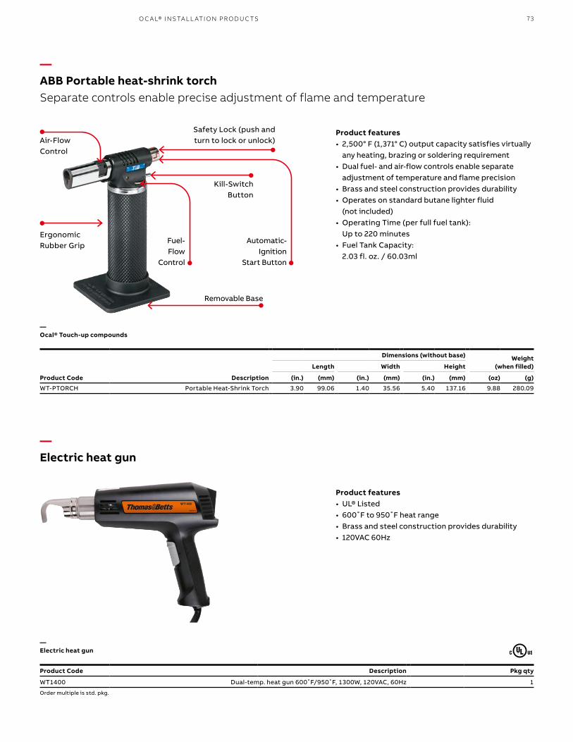
73O C A L® I NS TA L L ATI O N PR O D U C TS
Product Code Description Pkg qty
WT1400 Dual-temp. heat gun 600˚F/950˚F, 1300W, 120VAC, 60Hz 1
Order multiple is std. pkg.
Product features• 2,500° F (1,371° C) output capacity satisfies virtually
any heating, brazing or soldering requirement• Dual fuel- and air-flow controls enable separate
adjustment of temperature and flame precision• Brass and steel construction provides durability• Operates on standard butane lighter fluid
(not included)• Operating Time (per full fuel tank):
Up to 220 minutes• Fuel Tank Capacity:
2.03 fl. oz. / 60.03ml
Product features• UL® Listed• 600˚F to 950˚F heat range• Brass and steel construction provides durability• 120VAC 60Hz
—ABB Portable heat-shrink torchSeparate controls enable precise adjustment of flame and temperature
—Electric heat gun
Dimensions (without base) Weight (when filled)Length Width Height
Product Code Description (in.) (mm) (in.) (mm) (in.) (mm) (oz) (g)
WT-PTORCH Portable Heat-Shrink Torch 3.90 99.06 1.40 35.56 5.40 137.16 9.88 280.09
—Ocal® Touch-up compounds
—Electric heat gun
Ergonomic Rubber Grip
Safety Lock (push and turn to lock or unlock)
Automatic-Ignition
Start Button
Kill-Switch Button
Air-Flow Control
Removable Base
Fuel-Flow
Control

74 O C A L® CO R R OSI O N - R E SIS TA NT CO N D U IT S Y S TEMS
—Technical informationOcal® PVC exterior coating chemical resistance
Recommended Exposure
Solutions Conc. Temp. Splashing Liquid Fumes
Acetic Acid 10% 120 no no no
Acid Copper Plating Solution 160 yes yes yes
Alkaline Cleaners 160 yes yes yes
Aluminum Chloride Sat’d 160 yes yes yes
Aluminum Sulfate Sat’d 160 yes yes yes
Alums Sat’d 160 yes yes yes
Ammonium Chloride Sat’d 160 yes yes yes
Ammonium Hydroxide 28% 120 yes yes yes
Ammonium Hydroxide 10% 120 yes yes yes
Ammonium Sulfate Sat’d 160 yes yes yes
Ammonium Thiocyanate Sat’d 160 yes yes yes
Amyl Alcohol Any 90 yes yes yes
Arsenic Acids Any 150 yes yes yes
Barium Sulfide Sat’d 120 yes yes yes
Black Liquor Sat’d 90 yes yes yes
Benzoic Acid Sat’d 160 yes yes yes
Brass Plating Solution Any 160 yes yes yes
Bromine Water Sat’d 120 yes yes yes
Butyl Alcohol Any 90 yes yes yes
Cadmium Plating Solution Any 150 yes yes yes
Calcium Bisulfite Any 150 yes yes yes
Calcium Chloride Sat’d 160 yes yes yes
Calcium Hypochlorite Sat’d 120 yes yes yes
Carbonic Acid Sat’d 160 yes yes yes
Casein Sat’d 90 yes yes yes
Castor Oil Any 90 yes yes yes
Caustic Soda 35% 120 yes yes yes
Caustic Soda 10% 150 yes yes yes
Caustic Potash 35% 120 yes yes yes
Caustic Potash 10% 150 yes yes yes
Chlorine Water Sat’d 90 yes yes yes
Chromium Plating Solution Any 150 yes yes yes
Citric Acid Sat’d 160 yes yes yes
Copper Chloride (Cupric) Sat’d 160 yes yes yes
Copper Cyanide Plating Sol Any 160 yes yes yes
(High Speed) Any 180 yes yes yes
(with Alkali Cyanides) Sat’d 160 yes yes yes
Copper Sulfate Sat’d 160 yes yes yes
Coconut Oil Sat’d 90 yes yes yes
Cottonseed Oil Sat’d 90 yes yes yes
Disodium Phosphate Sat’d 160 yes yes yes
Ethyl Alcohol Any 90 yes yes yes
Ethylene Glycol Any 90 yes no yes
Ferric Chloride 45% 120 yes yes yes
Ferrous Sulfate Sat’d 150 yes yes yes
Fluoboric Acid Any 150 yes yes yes
Formaldehyde 37% 120 yes yes yes
Formic Acid 85% 100 no no no
Gallic Acid Sat’d 150 no no yes
Glucose Any 150 yes yes yes
Glue Any 150 yes yes yes
Glycerine Any 90 yes yes yes
Recommended Exposure
Solutions Conc. Temp. Splashing Liquid Fumes
Gold Plating Solution Any 150 yes yes yes
Hydrochloric Acid 10% 120 yes no yes
Hydrochloric Acid 21.50% 120 yes no yes
Hydrochloric Acid 37.50% 120 yes no yes
Hydrochloric Acid 37.50% 90 yes no yes
Hydrofluoric Acid 4% 140 yes no yes
Hydrofluoric Acid 10% 120 yes no yes
Hydrofluoric Acid 48% 120 yes no yes
Hydrogen Peroxide 30% 120 yes yes yes
Hydrogen Sulfide Sat’d 120 yes yes yes
Hydroquinone Any 90 yes yes yes
Indium Plating Solution Any 150 yes yes yes
Lactic Acid 50% 120 yes yes yes
Lactic Acid Any 90 yes yes yes
Lead Plating Solution Any 150 yes yes yes
Malic Acid Any 90 yes yes yes
Methyl Alcohol Any 90 yes yes yes
Mineral Oils Any 90 yes yes yes
Nickel Acetate Sat’d 160 yes yes yes
Nickel Plating Solution 160 yes yes yes
Nickel Salts Sat’d 160 yes yes yes
Nitric Acid 35% 120 yes no yes
Nitric Acid 40% 90 yes no yes
Nitric Acid 60% 120 yes no yes
Nitric Acid/ 15%
Hydrofluoric Acid 4% 140 yes yes yes
Nitric Acid/ 16%
Sodium Dichromate 13% 130 yes yes yes
Water 71%
Oleic Acid Any 90 yes yes yes
Oxalic Acid Sat’d 120 yes yes yes
Any 90 yes yes yes
Phenol Sat’d 120 no no no
Phosphoric Acid 75% 150 yes yes yes
Phosphoric Acid 85% 120 yes yes yes
Phosphoric Acid 85% 160 yes yes yes
Potassium Acid Sulfate Sat’d 150 yes yes yes
Potassium Antimonate Sat’d 150 yes yes yes
Potassium Bisulfite Sat’d 90 yes yes yes
Potassium Chloride Sat’d 160 yes yes yes
Potassium Cuprocyanide Sat’d 150 yes yes yes
Potassium Cyanide Sat’d 160 yes yes yes
Potassium Diachromate Sat’d 160 yes yes yes
Potassium Hypochlorite Sat’d 90 yes no yes
Potassium Sulfide Sat’d 150 yes yes yes
Potassium Thiosulfate Sat’d 150 yes yes yes
Propyl Alcohol Sat’d 150 yes yes yes
Rhodium Plating Solution Sat’d 150 yes yes yes
Silver Plating Solution Sat’d 150 yes yes yes
Soaps Any 90 yes yes yes
Sodium Acid Sulfate Sat’d 160 yes yes yes
Sodium Antimonate Sat’d 150 yes yes yes

75TECH N I C A L I N FO R M ATI O N
—Technical informationOcal® PVC exterior coating chemical resistance (continued)
—Ocal® Urethane interior coating chemical resistance
Recommended Exposure
Solutions Conc. Temp. Splashing Liquid Fumes
Sodium Bicarbonate Sat’d 160 yes yes yes
Sodium Bisulfite Sat’d 90 yes yes yes
Sodium Chloride Sat’d 160 yes yes yes
Sodium Cyanide Sat’d 160 yes yes yes
Sodium Dichromate Sat’d 160 yes yes yes
Sodium Hydroxide 10% 150 yes no yes
Sodium Hydroxide 35% 120 yes no yes
Sodium Hydroxide 73% 160 no no no
Sodium Hypochlorite Sat’d 90 yes no yes
Sodium Hypochlorite 15% 120 yes no yes
Sodium Sulfide Sat’d 150 yes yes yes
Sodium Thiosulfate Sat’d 150 yes yes yes
Sulfuric Acid 15% 120 yes yes yes
Sulfuric Acid 15% 160 yes yes yes
Sulfuric Acid 50% 120 yes yes yes
Recommended Exposure
Solutions Conc. Temp. Splashing Liquid Fumes
Acetic Acid 10% 75 yes no yes
Acid Copper Plating Solution Any 75 yes no yes
Alkaline Cleaners Any 75 yes no yes
Aluminum Chloride Sat’d 75 yes no yes
Aluminum Sulfate Sat’d 75 yes no yes
Alums Sat’d 75 yes no yes
Ammonium Chloride Sat’d 75 yes no yes
Ammonium Hydroxide 28% 75 yes no yes
Ammonium Hydroxide 10% 75 yes no yes
Ammonium Sulfate Sat’d 75 yes no yes
Ammonium Thiocyanate Sat’d 75 yes no yes
Amyl Alcohol Any 75 yes yes yes
Arsenic Acids Any 75 yes no yes
Barium Sulfide Sat’d 75 yes no yes
Black Liquor Sat’d 75 yes no yes
Benzoic Acid Sat’d 75 yes no yes
Brass Plating Solution Any 75 yes no yes
Bromine Water Sat’d 75 yes no yes
Butyl Alcohol Any 75 yes no yes
Cadmium Plating Solution Any 75 yes no yes
Calcium Bisulfite Any 75 yes no yes
Calcium Chloride Sat’d 75 yes no yes
Calcium Hypochlorite Sat’d 75 yes no yes
Carbonic Acid Sat’d 75 yes no yes
Casein Sat’d 75 yes no yes
Castor Oil Any 75 yes yes yes
Caustic Soda 35% 75 yes no yes
Caustic Soda 10% 75 yes no yes
Recommended Exposure
Solutions Conc. Temp. Splashing Liquid Fumes
Caustic Potash 35% 75 yes no yes
Caustic Potash 10% 75 yes no yes
Chlorine Water Sat’d 75 yes no yes
Chromium Plating Solution Any 75 yes no yes
Citric Acid Sat’d 75 yes no yes
Copper Chloride (Cupric) Sat’d 75 yes no yes
Copper Cyanide Plating Sol Any 75 yes no yes
(High Speed) Any 75 yes no yes
(with Alkali Cyanides) Sat’d 75 yes no yes
Copper Sulfate Sat’d 75 yes no yes
Coconut Oil Sat’d 75 yes yes yes
Cottonseed Oil Sat’d 75 yes yes yes
Disodium Phosphate Sat’d 75 yes no yes
Ethyl Alcohol Any 75 yes no yes
Ethylene Glycol Any 75 yes yes yes
Ferric Chloride 45% 75 yes no yes
Ferrous Sulfate Sat’d 75 yes no yes
Fluoboric Acid Any 75 yes no yes
Formaldehyde 37% 75 yes no yes
Formic Acid 85% 75 yes no yes
Gallic Acid Sat’d 75 yes no yes
Glucose Any 75 yes yes yes
Glue Any 75 yes no yes
Glycerine Any 75 yes yes yes
Gold Plating Solution Any 75 yes no yes
Hydrochloric Acid 10% 75 yes no yes
Hydrochloric Acid 21.50% 75 yes no yes
Hydrochloric Acid 37.50% 75 yes no yes
Recommended Exposure
Solutions Conc. Temp. Splashing Liquid Fumes
Sulfuric Acid 70% 90 yes no yes
Sulfuric Acid 98.00% 100 no no yes
Sulfurous Acid 2% 120 yes no yes
Sulfurous Acid 6% 120 yes no yes
Tannic Acid Sat’d 90 yes yes yes
Tartaric Acid Sat’d 90 yes yes yes
Tin Chloride Aqueous Sat’d 150 yes yes yes
Tin Plating Solution Sat’d 150 yes yes yes
Triethaneolamine Sat’d 150 yes yes yes
Trisodium Phosphate Sat’d 150 yes yes yes
Water Sat’d 160 yes yes yes
White Liquor 90 yes yes yes
Zinc Plating Solution 160 yes yes yes
Zinc Sulfate Sat’d 160 yes yes yes

76 O C A L® CO R R OSI O N - R E SIS TA NT CO N D U IT S Y S TEMS
—Technical informationOcal® Urethane interior coating chemical resistance (continued)
Recommended Exposure
Solutions Conc. Temp. Splashing Liquid Fumes
Hydrofluoric Acid 4.00% 75 yes no yes
Hydrofluoric Acid 10% 75 yes no yes
Hydrofluoric Acid 48% 75 yes no yes
Hydrogen Peroxide 30% 75 yes no yes
Hydrogen Sulfide Sat’d 75 yes no yes
Hydroquinone Any 75 yes no yes
Indium Plating Solution Any 75 yes no yes
Lactic Acid 50% 75 yes no yes
Lactic Acid Any 75 yes no yes
Lead Plating Solution Any 75 yes no yes
Malic Acid Any 75 yes no yes
Methyl Alcohol Any 75 yes no yes
Mineral Oils Any 75 yes yes yes
Nickel Acetate Sat’d 75 yes no yes
Nickel Plating Solution 75 yes no yes
Nickel Salts Sat’d 75 yes no yes
Nitric Acid 35% 75 yes no yes
Nitric Acid 40% 75 yes no yes
Nitric Acid 60% 75 yes no yes
Nitric Acid/ 15%
Hydrofluoric Acid 4% 75 yes no yes
Nitric Acid/ 16%
Sodium Dichromate 13% 75 yes no yes
Water 71%
Oleic Acid Any 75 yes no yes
Oxalic Acid Sat’d 75 yes no yes
Any 75 yes no yes
Phenol Sat’d 75 yes no yes
Phosphoric Acid 75% 75 yes no yes
Phosphoric Acid 85% 75 yes no yes
Potassium Antimonate Sat’d 75 yes no yes
Potassium Bisulfite Sat’d 75 yes no yes
Potassium Chloride Sat’d 75 yes no yes
Potassium Cuprocyanide Sat’d 75 yes no yes
Potassium Cyanide Sat’d 75 yes no yes
Potassium Diachromate Sat’d 75 yes no yes
Potassium Hypochlorite Sat’d 75 yes no yes
Recommended Exposure
Solutions Conc. Temp. Splashing Liquid Fumes
Potassium Sulfide Sat’d 75 yes no yes
Potassium Thiosulfate Sat’d 75 yes no yes
Propyl Alcohol Sat’d 75 yes no yes
Rhodium Plating Solution Sat’d 75 yes no yes
Silver Plating Solution Sat’d 75 yes no yes
Soaps Any 75 yes no yes
Sodium Acid Sulfate Sat’d 75 yes no yes
Sodium Antimonate Sat’d 75 yes no yes
Sodium Bicarbonate Sat’d 75 yes no yes
Sodium Bisulfite Sat’d 75 yes no yes
Sodium Chloride Sat’d 75 yes no yes
Sodium Cyanide Sat’d 75 yes no yes
Sodium Dichromate Sat’d 75 yes no yes
Sodium Hydroxide 10% 75 yes no yes
Sodium Hydroxide 35% 75 yes no yes
Sodium Hydroxide 73% 75 yes no yes
Sodium Hypochlorite Sat’d 75 yes no yes
Sodium Hypochlorite 15% 75 yes no yes
Sodium Sulfide Sat’d 75 yes no yes
Sodium Thiosulfate Sat’d 75 yes no yes
Sulfuric Acid 15% 75 yes no yes
Sulfuric Acid 50% 75 yes no yes
Sulfuric Acid 70% 75 yes no yes
Sulfuric Acid 98% 75 yes no yes
Sulfurous Acid 2% 75 yes no yes
Sulfurous Acid 6% 75 yes no yes
Tannic Acid Sat’d 75 yes no yes
Tartaric Acid Sat’d 75 yes no yes
Tin Chloride Aqueous Sat’d 75 yes no yes
Tin Plating Solution Sat’d 75 yes no yes
Triethaneolamine Sat’d 75 yes no yes
Trisodium Phosphate Sat’d 75 yes no yes
Water Sat’d 75 yes no yes
White Liquor 75 yes no yes
Zinc Plating Solution 75 yes no yes
Zinc Sulfate Sat’d 75 yes no yes

77TECH N I C A L I N FO R M ATI O N
—Technical informationOcal® Guide Specification:
Section 26 05 33 — Underground Ducts and Raceways for Electrical Systems:
Conduit Systems for Use in Corrosive Environments
2.1 GeneralA. Furnish PVC-coated ERMC of size as indicated. If not indicated, the smallest trade size shall be 3 ⁄4 in. The PVC-coated ERMC system shall include necessary PVC-coated fittings, boxes and covers to form a complete encapsulated system.
2.2 ManufacturersA. Acceptable Manufacturers: ABB Corporation; Electrification Products division 860 Ridge Lake Blvd., Memphis, TN 38120. Tel: 901-252-5000. Web: www.tnb.com..B. Substitutions: Not permitted. C. Requests for substitutions will be considered in accordance with provisions of Section 01 25 00.
1.3 Materials/Components
A. Pvc-coated rigid steel conduit The PVC-coated rigid steel conduit shall be hot-dip galvanized inside and out with hot-dip galvanized threads. The interior galvanizing shall be listed per UL 6. The exterior galvanizing shall be listed per UL 6 as primary corrosion protection. Thread protectors shall be used on the exposed threads of the PVC-coated conduit. PVC-coated ERMC steel conduit shall comply with UL 6, ANSI C80.1 and NEMA RN 1 standards without exception.
The PVC coating, in compliance with NEMA RN 1, shall be nominal 40 mils in thickness continuous over the entire length of the conduit except at the threads and be free of blisters, bubbles or pinholes. PVC shall be UL listed as a primary corrosion protection.
A blue urethane coating shall be uniformly and consistently applied to the interior of conduit. This internal coating shall be a nominal 2 mils thickness. All male threads on elbows and nipples shall be protected by this same application of urethane coating.
Coated couplings shall be used with coated conduit. The thickness of the coating on couplings shall be at least equal to the thickness of the coating on the conduit. Each coated coupling shall have a flexible PVC sleeve which extends from each end of the coupling and which will overlap the PVC coating on the conduit when the coupling has been installed on the conduit.
1.1 SummaryA. Section Includes: Furnishing, installation and assembly of PVC-coated electrical rigid metal conduit (ERMC) systems and stainless steel fittings.B. Related Sections 1. Section 26 05 29 – Hangers and Supports for Electrical Systems
1.2 ReferencesA. National Electrical Manufacturers Association (NEMA) 1. NEMA RN 1: Polyvinyl-Chloride (PVC) Externally Coated Galvanized Rigid Steel Conduit and Intermediate Metal ConduitB. National Fire Protection Association (NFPA) 1. NFPA 70: National Electrical Code® (NEC®) C. American Society for Testing and Materials (ASTM): 1. ASTM A 239: Standard Practice for Locating the Thinnest Spot in a Zinc (Galvanized) Coating on Iron or Steel ArticlesD. Underwriters Laboratories, Inc. (UL®) 1. UL 6: Safety Standard for Rigid Metal Conduit 2. UL 514B: Safety Standard for Fittings for Conduit and Outlet BoxesE. American National Standards Institute (ANSI) 1. ANSI C80.1: American National Standard for Rigid Steel Conduit – Zinc Coated G. Steel Tube Institute of North America 1. Guidelines for Installing Steel Conduit/Tubing
1.3 SubmittalsA. General: Submit in accordance with Section 01 33 00.B. Product Data 1. Manufacturer’s descriptive literature and product specifications for each product. 2. Manufacturer’s installation literature and training guide. 3. Manufacturer’s product drawings, when applicable.
1.4 Quality AssuranceA. Manufacturer Qualifications: Products shall be free of defects in material and workmanship.B. Installer Qualifications: Installer shall be trained and certified based on the acceptable manufacturer’s listed requirements.
Part 1 – General Part 2 – Products

78 O C A L® CO R R OSI O N - R E SIS TA NT CO N D U IT S Y S TEMS
—Technical informationOcal® Guide Specification (continued):
up through 2 in. For sizes 2–6 in., the length of the sleeve extension(s) shall be at least 2 in. The PVC sleeve shall be a nominal thickness of 40 mils in thickness. The inside diameter of the overlapping sleeve shall be less than the outside diameter of the PVC-coated conduit.
C. PVC-coated ordinary location fittings PVC-coated ferrous and aluminum fittings for general service and corrosive locations must be UL listed. The PVC coating shall be minimum 40 mils in thickness and be free of blisters, bubbles or pinholes. Female threads on fittings shall be protected by application of urethane coating.
All female ends of PVC-coated conduit fittings shall have a flexible PVC sleeve which extends from the female ends of the fitting and which will overlap the PVC coating on the conduit when the fitting has been installed on the conduit. The length of the sleeve extension(s) shall be at least equivalent to the nominal conduit size for sizes up through 2 in. For sizes 2–6 in., the length of the sleeve extension(s) shall be at least 2 in. The PVC sleeve shall be a nominal thickness of 40 mils in thickness. The inside diameter of the overlapping sleeve shall be less than the outside diameter of the PVC-coated conduit.
1. The PVC coating on all form 8 covers shall form a gasketlike flange of at least 5⁄16 in. wide and minimum 40 mils covering the top of the fitting around the opening and the bottom of the cover/ matting with the flange of the fitting. A blue urethane coating shall be uniformly and consistently applied to the interior, exterior and threads of all conduit bodies, including but not limited to form 8 and form 7 conduit bodies. This coating shall be a nominal 2 mils thickness. Stainless steel encapsulated screws shall be Supplied with all form 7 and form 8 fittings.
2. Rigid hubs shall have a nominal 40 mils PVC coating thickness with a nominal 2 mils of blue urethane on interior and threads. The male threads and locknut shall remain uncoated. 3. Liquidtight fittings shall have an exterior PVC coating of a minimum thickness of nominal 40 mils.
The length of the sleeve extension(s) shall be at least equivalent to the nominal conduit size for sizes up through 2 in. For sizes 2–6 in., the length of the sleeve extension(s) shall be at least 2 in. The PVC sleeve shall be a nominal thickness of 40 mils in thickness. The inside diameter of the overlapping sleeve shall be less than the outside diameter of the PVC-coated conduit.
The PVC coating, in compliance with NEMA RN 1, shall be nominal 40 mils in thickness continuous over the entire length of the conduit except at the threads and be free of blisters, bubbles or pinholes. PVC shall be UL listed as a primary corrosion protection.
A blue urethane coating shall be uniformly and consistently applied to the interior of conduit. This internal coating shall be a nominal 2 mils thickness. All male threads on elbows and nipples shall be protected by this same application of urethane coating.
Coated couplings shall be used with coated conduit. The thickness of the coating on couplings shall be at least equal to the thickness of the coating on the conduit. Each coated coupling shall have a flexible PVC sleeve which extends from each end of the coupling and which will overlap the PVC coating on the conduit when the coupling has been installed on the conduit.
B. PVC-coated rigid steel conduit The PVC-coated ERMC aluminum conduit prior to coating shall be UL listed. The exterior of the conduit shall have a PVC coating of a minimum thickness of nominal 40 mils.
A blue urethane coating shall be uniformly and consistently applied to the interior of conduit. This internal coating shall be a nominal 2 mils thickness. All male threads on elbows and nipples shall be protected by this same application of urethane coating.
Coated couplings shall be used with coated conduit. The thickness of the coating on couplings shall be at least equal to the thickness of the coating on the conduit. Each coated coupling shall have a flexible PVC sleeve which extends from each end of the coupling and which will overlap the PVC coating on the conduit when the coupling has been installed on the conduit. The length of the sleeve extension(s) shall be at least equivalent to the nominal conduit size for sizes

79TECH N I C A L I N FO R M ATI O N
—Technical informationOcal® Guide Specification (continued):
D. PVC-coated hazardous location fittings Hazardous location fittings prior to PVC coating must be UL listed. All female ends of PVC-coated conduit fittings shall have a flexible PVC sleeve which extends from the female ends of the fitting and which will overlap the PVC coating on the conduit when the fitting has been installed on the conduit. The length of the sleeve extension(s) shall be at least equivalent to the nominal conduit size for sizes up through 2 in. For sizes 2–6 in., the length of the sleeve extension(s) shall be at least 2 in. The PVC sleeve shall be a nominal thickness of 0 mils in thickness. The inside diameter of the overlapping sleeve shall be less than the outside diameter of the PVC-coated conduit.
E. PVC-coated strut, hangers and clamps Right-angle beam clamps and U-bolts shall be specially formed and sized to fit snugly the outside diameter of the PVC-coated conduit. Support products such as ferrous strut, beam clamps, pipe straps, clamp back spacers, conduit clamp hangers and all-thread rods shall have a minimum 15-mil PVC coating by the manufacturer of the ERMC conduit and system components.
F. Stainless steel fittings Stainless steel liquid-tight fittings shall be made of 304-grade stainless steel or better.
G. Stainless steel strut, hangers, etc. Stainless steel strut, beam clamps, pipe straps, clamp back spacers, conduit clamp hangers and all-thread rods shall be made of 304-grade stainless steel or better.
3.1 ExaminationA. The PVC-coated ERMC and system components have been selected for use in an atmosphere considered to be corrosive for this project. The corrosive atmosphere is considered to be more damaging than merely the presence of moisture. Accordingly, conduit and the corresponding fittings for it must have PVC protection as described under Part 2 – Products. Conduit and fittings that are merely galvanized for this purpose are insufficient.
3.2 PreparationA. Preparation shall be done in accordance with manufacturer’s printed instructions.
3.3 InstallationA. Install in accordance with manufacturer’s printed instructions and manufacturer’s installation training.
3.4 Quality controlA. General: Comply with requirements of Section 01 45 13.
3.5 Manufacturer’s field servicesA. Free on-site installation training course by company representative. This representative must conduct the on-site training course in order to qualify for the installation certificate. The time required for this training is estimated to be two (2) hours.B. After the on-site training installation, the representative shall then register the installer in his database and provide certification for installation.
End of section
Part 3 – Execution
Notes 1. Ocal ® PVC-coated conduit and fittings are not recommended for use in areas where they will be exposed to sustained temperatures above 200 degrees Fahrenheit or exposed to fire. Prolonged exposure to heat greater than 200 degrees Fahrenheit or exposure to fire may cause the plastic coatings to release harmful emissions, posing a potential health hazard to persons subjected to such emissions.
2. If subjected to sustained flame or sustained heat above 400 degrees Fahrenheit, PVC will burn. PVC is self- extinguishing at room temperature.
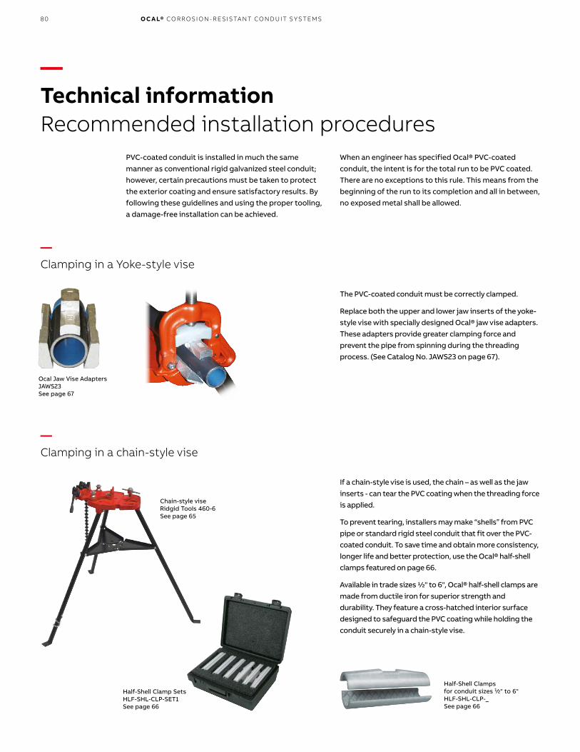
80 O C A L® CO R R OSI O N - R E SIS TA NT CO N D U IT S Y S TEMS
—Clamping in a Yoke-style vise
—Clamping in a chain-style vise
The PVC-coated conduit must be correctly clamped.
Replace both the upper and lower jaw inserts of the yoke-style vise with specially designed Ocal® jaw vise adapters. These adapters provide greater clamping force and prevent the pipe from spinning during the threading process. (See Catalog No. JAWS23 on page 67).
When an engineer has specified Ocal® PVC-coated conduit, the intent is for the total run to be PVC coated. There are no exceptions to this rule. This means from the beginning of the run to its completion and all in between, no exposed metal shall be allowed.
PVC-coated conduit is installed in much the same manner as conventional rigid galvanized steel conduit; however, certain precautions must be taken to protect the exterior coating and ensure satisfactory results. By following these guidelines and using the proper tooling, a damage-free installation can be achieved.
If a chain-style vise is used, the chain – as well as the jaw inserts - can tear the PVC coating when the threading force is applied.
To prevent tearing, installers may make “shells” from PVC pipe or standard rigid steel conduit that fit over the PVC-coated conduit. To save time and obtain more consistency, longer life and better protection, use the Ocal® half-shell clamps featured on page 66.
Available in trade sizes 1⁄2" to 6", Ocal® half-shell clamps are made from ductile iron for superior strength and durability. They feature a cross-hatched interior surface designed to safeguard the PVC coating while holding the conduit securely in a chain-style vise.
—Technical informationRecommended installation procedures
Ocal Jaw Vise Adapters JAWS23 See page 67
Half-Shell Clampsfor conduit sizes 1⁄2" to 6"HLF-SHL-CLP-_See page 66
Half-Shell Clamp SetsHLF-SHL-CLP-SET1See page 66
Chain-style viseRidgid Tools 460-6See page 65

81
—Technical informationCutting with a band saw cutter
—Cutting with a roller-style cutter
A band saw cutter will cut the PVC coating flush with the end of the conduit. PVC material cut flush to the end of the conduit will not allow the die teeth to bite into the steel to start the threading process.
Before threading, remove approximately 1 ⁄4" of the PVC coating from the end of the conduit. Using a knife, whittle in a pencil-sharpening style, cutting the coating from the conduit. A wire brush may also be used to remove PVC coating.
A band saw cutter will not easily cut the conduit at a“perfect” 90° angle (the accuracy of this cut depends heavily on the skill of the operator).
A roller-style cutter is the recommended tool for cutting Ocal® PVC-coated conduit.
A roller-style cutter cuts the edge of the conduit at a bevel and removes 1 ⁄4" of the coating at the same time. In addition, a roller-style cutter provides an exact 90° cut in relation to the conduit. No additional removal of PVC coating is necessary.
≠90°
Steel Pipe CuttersP70045C, P70060CSee page 67
TECH N I C A L I N FO R M ATI O N

82 O C A L® CO R R OSI O N - R E SIS TA NT CO N D U IT S Y S TEMS
—Technical informationManual and hand-held threading
PVC-coated conduit has a larger outer diameter than uncoated conduit. Standard dies will not clear the additional thickness. Hand-held as well as power threading devices require a die head for the correct size conduit. The standard die head is factory set for rigid conduit and will not fit over PVC coating.
Proper sized die heads are available from Ocal®, machined for use with PVC-coated conduit. Standard dies can also be machined to the proper size.
The following procedure is required for machined dies:
1. Remove the cover plate and the four die teeth.2. Remove 100 thousandths of an inch (1 ⁄10") from the throat and collar diameter of the die head.3. Replace the dies and cover.
Ridgid Tools #700 threaderSee page 65
Remove 1⁄10"
—01 Throat & Collar Shown —02 Cover Plate Shown —03 The die teeth are cutting tapered threads and willbecome clogged with PVC and metal shavings. —04 To prevent clogging, use a knife and score the conduit lengthwise from the point where the threads will endto where they begin. This will allow the PVC and metal shavings to fall into the throat of the die head.
—01
—02
—03
—04
51862

83
—01
—02
—03
—01 Ream the conduit with approved reamers. Spiral and straight-style reamers are both acceptable. —02 Ocal® Urethane Patching CompoundSee page 71—03 KOPR-SHIELD®See page 70
Rothenberger Reamer70289See page 68
—Technical informationHand-held powered threading
HandheldThe Ridgid #12R is typically used for smaller size conduit. The ratchet knob indicates forward and reverse. Die heads snap in from both sides and lock in place. (#12R includes ratchet and handle only)
Handheld poweredThe Ridgid 700 Power Drive is a heavy duty handheld tool typically used for conduit up to 2 inches diameter. The 700 Power Drive is designed for Ridgid 12R dies, available in both 115V and 230V models. Optional case is available for this tool.
TECH N I C A L I N FO R M ATI O N
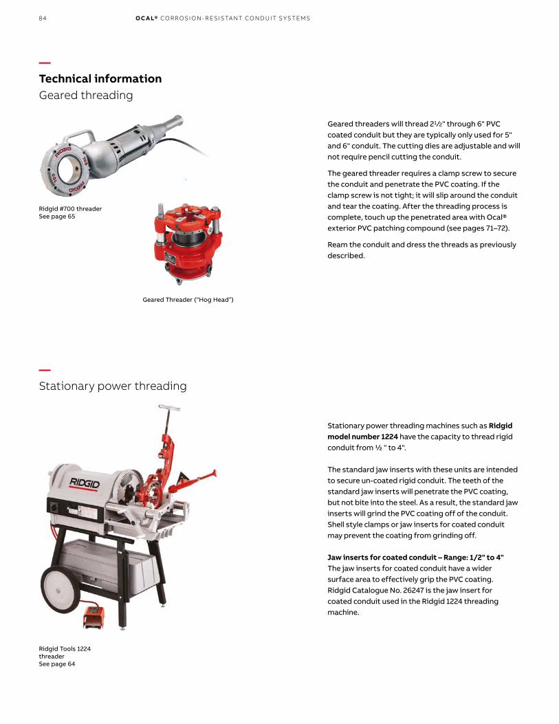
84 O C A L® CO R R OSI O N - R E SIS TA NT CO N D U IT S Y S TEMS
—Technical informationGeared threading
Geared threaders will thread 21 ⁄2" through 6" PVC coated conduit but they are typically only used for 5" and 6" conduit. The cutting dies are adjustable and will not require pencil cutting the conduit.
The geared threader requires a clamp screw to secure the conduit and penetrate the PVC coating. If the clamp screw is not tight; it will slip around the conduit and tear the coating. After the threading process is complete, touch up the penetrated area with Ocal® exterior PVC patching compound (see pages 71–72).
Ream the conduit and dress the threads as previously described.
—Stationary power threading
Geared Threader (“Hog Head”)
Ridgid Tools 1224 threaderSee page 64
Ridgid #700 threaderSee page 65
Stationary power threading machines such as Ridgid model number 1224 have the capacity to thread rigid conduit from ½ " to 4".
The standard jaw inserts with these units are intended to secure un-coated rigid conduit. The teeth of the standard jaw inserts will penetrate the PVC coating, but not bite into the steel. As a result, the standard jaw inserts will grind the PVC coating off of the conduit. Shell style clamps or jaw inserts for coated conduit may prevent the coating from grinding off.
Jaw inserts for coated conduit – Range: 1/2" to 4"The jaw inserts for coated conduit have a widersurface area to effectively grip the PVC coating.Ridgid Catalogue No. 26247 is the jaw insert forcoated conduit used in the Ridgid 1224 threadingmachine.

85
—Technical informationBending and hand bending
Bending Never use any type of lubricant on the shoes of a bending device. Use rubbing alcohol to clean the shoe prior to bending.
Hand bending
A standard hand bender can be used for saddles,offsets and conventional bending. For PVC-coatedconduit, the next larger shoe size from the EMT sizeshould be used. The table below shows the catalognumbers of the hand benders on page 63 and thecorresponding size of PVC-coated conduit onwhich they should be used.
Product Code PVC-Coated Conduit Size
35220 1 ⁄2"
35225 3 ⁄4"
2424A8 1"
Chicago Bender Hand BenderSee page 63
Ocal ® Heat-Cure PatchSee page 71
Ocal ® Air-Cure Patching CompoundsSee page 72
Ocal® Heat-Cure Patch offers a thicker consistency at higherambient temperatures than standard air-cure compounds,helping ensure better coverage and a more effective patchin warm weather applications.
TECH N I C A L I N FO R M ATI O N

86 O C A L® CO R R OSI O N - R E SIS TA NT CO N D U IT S Y S TEMS
—Technical informationElectric bending
—Hydraulic bending
These machines are designed for bending 1 ⁄2" through 2" conduit. The shoes as well as the roller assembly should be of the design for use with PVC-coated conduit. Listed along with the Greenlee® electric bender on page 61 are the bending accessories to equip the machine for PVC-coated conduit.
Coventional shoes on an electric bender and each of the rollers in the roller assembly must be machined to 60 thousandths. Although manufacturers use slide bars instead of a roller assembly, they must also be machined 60 thousandths. Compensate for “spring back,” since PVC coating often requires the setting to be off as much as 5°.
The preferred style of bending for 21 ⁄2" and larger size conduit. The shoe assembly should be of the design for PVC-coated conduit. The roller wheel and/or slide bar will accommodate PVC-coated conduit without the need for machining.
Greenlee Hydraulic Bending Tool
Shoe for Greenlee Hydraulic Bending Tool
Greenlee ® Model 555 Bender and bending accessories for PVC-coated conduit See page 63
Note Sequential bends can be manufactured by Ocal upon request.5" and 6" conduit must be bent at the factory.

87TECH N I C A L I N FO R M ATI O N
—Technical informationNEMA Standards Publication No. RN 1–2005
The length of the sleeve extension(s) shall be at least equivalent to the nominal conduit size for sizes up through NPS 2 (53). For sizes NPS 21 ⁄2 (63) through NPS 6 (155), the length of the sleeve extension(s) shall be at least 2 in. (50.8mm).
The PVC sleeve shall be a nominal thickness of .040 in (1.02mm). The inside diameter (I.D.) of the overlapping sleeve shall be less than the outside diameter (O.D.) of the PVC-coated conduit.
3.6 Workmanship and appearanceThe PVC coating shall be free of blisters, bubbles and pinholes. The PVC coating shall be continuous over the entire length of the conduit except at the threads and shall be holiday-free at the time of manufacture.
A holiday is herein defined as an electrical discontinuity of less than 80,000 ohms equivalent resistance sensed with a cellulose sponge wet with a suitable electrolyte and measured with an appropriate low voltage directcurrent instrument. A suitable electrolyte is a solution containing tap water, 3.0% salt (sodium chloride) and .5% liquid detergent.
The inside of the PVE-coated conduit, couplings and elbows shall be free of the PVC coating material.
All sleeve extensions shall be square cut.
3.7 Performance requirementsTypical physical requirements for PVC-coated conduit are given in Table 3.2.
3.8 AdhesionThe adhesion of the PVC coating to the conduit shall be greater than the strength of the coating itself. This shall be determined by making two circumferential cuts, above 1 ⁄2 in. (12.7mm) apart, through the plastic to the substrate. A third cut shall be made perpendicular to and crossing the circumferential cuts. The edge of the plastic shall be carefully lifted with a knife to form a plastic tab. This tab shall be pulled perpendicular to the conduit with a pair of pliers. The plastic tab shall tear rather than any additional coating film separating from the substrate.
3.1 ThicknessThe thickness of polyvinyl chloride (PVC) coatings shall be a nominal .040 in. (1.02mm). The tolerance on the coating thickness shall be +.010 in. (.25mm) or -.005 in. (.13mm).
3.2 Coating MaterialThe PVC coating shall have the properties specified in Table 3.1.
3.3 Application of coating
3.3.1 CleaningThe exterior surface that is to receive the coating shall be free of grease, oil, dirt and other extraneous matter. The surface shall be cleaned in such a manner that the galvanized surface of the conduit is not harmed or eroded.
3.3.2 PrimingThe cleaned exterior surface shall be primed with an adhesive suitable for use with the PVC coating material to be applied.
3.3.3 CoatingThe PVC material shall be applied in powder, plastisol or pellet form by a manufacturing method which will produce a finished product conforming to these standards.
3.4 ElbowsCoated elbows shall be used with coated conduit. The thickness of the coating on elbows shall be in accordance with Section 3.1.
3.5 CouplingsCoated couplings shall be used with coated conduit. The thickness of the coating on couplings shall be at least equal to the thickness of the coating on the conduit.
Each coated coupling shall have a flexible PVC sleeve which extends from each end of the coupling and which will overlap the PVC coating on the conduit when the coupling has been installed on the conduit.
Section 3 – External coatings
Minimum Requirement
ASTM Test MethodProperty
Hardness:
Shore A 75 D 2240
Shore D 25 D 2240
Tensile Strength 2,000 psi D 638
Elongation 200% D 638
Dielectric Strength 325 volts per mil D 149
Brittleness Temperature 5° F D 1790
—Properties of PVC coatings – Table 3.1
Property Requirement* Test Method
Abrasion Resistance 200 hours, no failure ASTM G6
Bendability, Radius 9 in. ASTM G10
Elongation (228.6mm)
Artificial Weathering Minimum 1,000 hours, ASTM G153no adverse effect
* The above requirements are based on testing a .040 in. (1.02mm) PVC coating applied over NPS 3 ⁄4 inch galvanized rigid steel conduit. See Section 1 for information on the ASTM test methods.
—Typical physical properties of PVC-coatedrigid conduit and IMC– Table 3.2

88 O C A L® CO R R OSI O N - R E SIS TA NT CO N D U IT S Y S TEMS
—Notes

89I N D E X & USEFU L I N FO R M ATI O N

90 O C A L® CO R R OSI O N - R E SIS TA NT CO N D U IT S Y S TEMS
Additional informationWe reserve the right to make technical changes or modify the contents of this document without prior notice. With regard to purchase orders, the agreed particulars shall prevail. ABB AG does not accept any responsibility whatsoever for potential errors or possible lack of information in this document.
We reserve all rights in this document and in the subject matter and illustrations contained therein. Any reproduction, disclosure to third parties or utilization of its contents – in whole or in parts – is forbidden without prior written consent of ABB AG.

91

© Copyright 2019 ABB. All rights reserved. Specifications subject to change without notice. 7T
KK
00
012
6 R
EV
A 1
8.0
3.20
20
—USABB Installation ProductsElectrification Products division 860 Ridge Lake Blvd.Memphis, TN 38120+1 901-252-5000
tnb.abb.com
For other ABB locations visit new.abb.com/low-voltage
—CanadaABB Installation ProductsElectrification Products division 700 Thomas AvenueSaint-Jean-sur-RichelieuQuebec, J2X 2M9+1 450-347-5318
tnb.ca.abb.com