
Catalog Number KTA7-25S.. - NHP Electrical...F20 SSNA9000 Motor Circuit Controllers F KT7 Discount...
19
F20 SSNA9000 Motor Circuit Controllers F KT7 Discount Schedule A-1 ➊ No backup fuse required. Technical Information KT7 Motor Circuit Controller IEC Performance Data Catalog Number KTA7-25S...32S 0.16A 0.25A 0.4A 0.63A 1A 1.6A 2.5A 4A 6.3A 10A 16A 20A 25A 29A 32A Rated Operational Current, I e [A] 0.16 0.25 0.4 0.63 1 1.6 2.5 4 6.3 10 16 20 25 29 32 Magnetic Release Current [A] 2.1 3.3 5.2 8.2 13 21 33 52 82 130 208 260 325 406 448 Switching of Standard Three-Phase Motors AC-2, AC-3 230/240V [kW] ~ ~ ~ 0.09 0.18 0.25 0.37 0.75 1.5 2.2 4.0 5.5 5.5 7.5 7.5 400/415V [kW] 0.02 0.04 0.09 0.18 0.25 0.55 0.75 1.5 2.2 4.0 7.5 10 11 13 15 500V [kW] 0.06 0.09 0.12 0.18 0.37 0.75 1.1 2.2 3.0 6.3 10 11 15 18.5 20 690V [kW] 0.06 0.09 0.18 0.25 0.55 1.1 1.8 3.0 4.0 7.5 13 17 22 25 25 Back-up Fuses gG, gL, only if I cc ≥ I cu 230/240V [A] ➊ ➊ ➊ ➊ ➊ ➊ ➊ ➊ ➊ ➊ ➊ 100 100 125 125 400/415V [A] ➊ ➊ ➊ ➊ ➊ ➊ ➊ ➊ ➊ ➊ 80 100 100 125 125 440/460V [A] ➊ ➊ ➊ ➊ ➊ ➊ ➊ ➊ ➊ 63 63 80 80 100 100 500V [A] ➊ ➊ ➊ ➊ ➊ ➊ ➊ ➊ ➊ 80 80 80 80 100 100 690V [A] ➊ ➊ ➊ ➊ ➊ 16 20 35 50 50 63 63 63 80 80 Ultimate Short-Circuit Breaking Capacity I cu 230/240V [kA] 100 100 100 100 100 100 100 100 100 100 100 50 50 50 50 400/415V [kA] 100 100 100 100 100 100 100 100 100 100 65 50 15 15 15 440/460V [kA] 100 100 100 100 100 100 100 100 100 50 10 6 6 6 6 500V [kA] 100 100 100 100 100 100 100 100 100 50 10 6 6 6 6 690V [kA] 100 100 100 100 100 8 8 8 4 4 3 3 3 3 3 Rated Service Short-Circuit Breaking Capacity I cs 230/240V [kA] 100 100 100 100 100 100 100 100 100 100 100 50 50 25 25 400/415V [kA] 100 100 100 100 100 100 100 100 100 100 50 15 15 15 15 440/460V [kA] 100 100 100 100 100 100 100 100 100 50 6 6 6 6 6 500V [kA] 100 100 100 100 100 100 100 100 100 50 6 6 6 6 6 690V [kA] 100 100 100 100 100 8 8 8 4 4 3 3 3 3 3
Transcript of Catalog Number KTA7-25S.. - NHP Electrical...F20 SSNA9000 Motor Circuit Controllers F KT7 Discount...
F20
SSNA
9000
Mot
or C
ircui
t Co
ntro
llers
F
KT7
Discount Schedule A-1
➊No backup fuse required.
Technical InformationKT7 Motor Circuit Controller
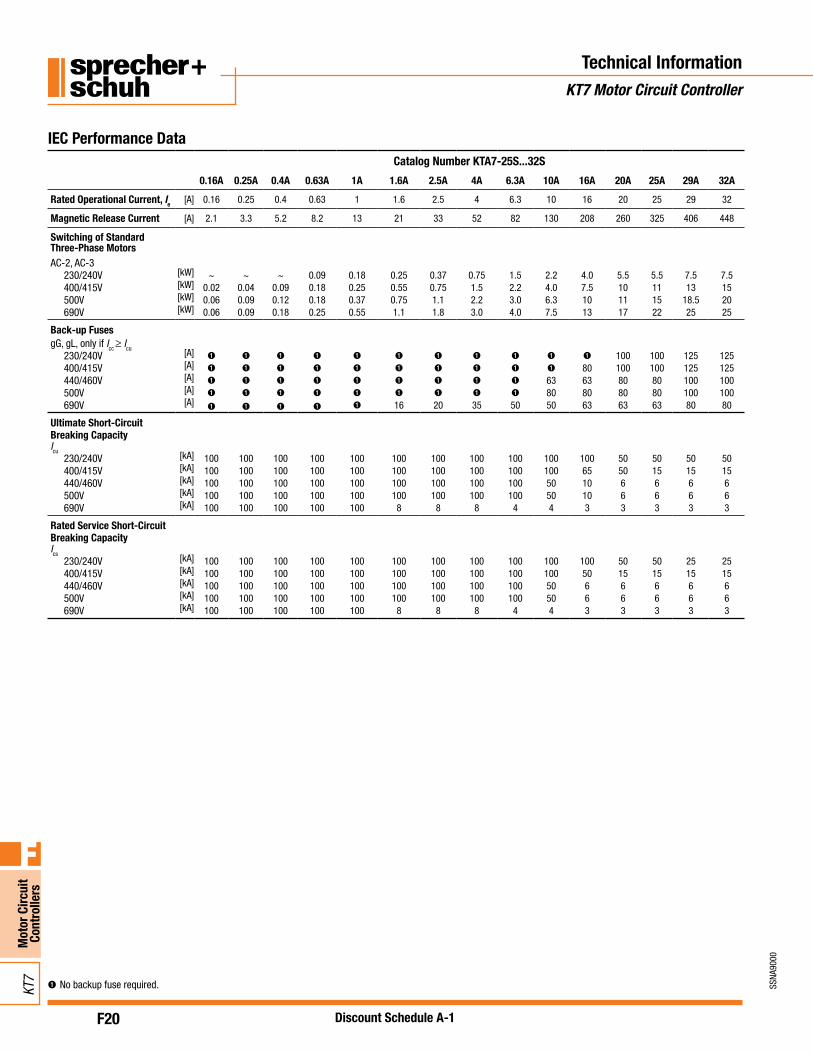
IEC Performance DataCatalog Number KTA7-25S...32S
0.16A 0.25A 0.4A 0.63A 1A 1.6A 2.5A 4A 6.3A 10A 16A 20A 25A 29A 32A
Rated Operational Current, Ie[A] 0.16 0.25 0.4 0.63 1 1.6 2.5 4 6.3 10 16 20 25 29 32
Magnetic Release Current [A] 2.1 3.3 5.2 8.2 13 21 33 52 82 130 208 260 325 406 448
Switching of StandardThree-Phase MotorsAC-2, AC-3
230/240V [kW] ~ ~ ~ 0.09 0.18 0.25 0.37 0.75 1.5 2.2 4.0 5.5 5.5 7.5 7.5400/415V [kW] 0.02 0.04 0.09 0.18 0.25 0.55 0.75 1.5 2.2 4.0 7.5 10 11 13 15500V [kW] 0.06 0.09 0.12 0.18 0.37 0.75 1.1 2.2 3.0 6.3 10 11 15 18.5 20690V [kW] 0.06 0.09 0.18 0.25 0.55 1.1 1.8 3.0 4.0 7.5 13 17 22 25 25
Back-up FusesgG, gL, only if Icc ≥ Icu
230/240V [A] ➊ ➊ ➊ ➊ ➊ ➊ ➊ ➊ ➊ ➊ ➊ 100 100 125 125400/415V [A] ➊ ➊ ➊ ➊ ➊ ➊ ➊ ➊ ➊ ➊ 80 100 100 125 125440/460V [A] ➊ ➊ ➊ ➊ ➊ ➊ ➊ ➊ ➊ 63 63 80 80 100 100500V [A] ➊ ➊ ➊ ➊ ➊ ➊ ➊ ➊ ➊ 80 80 80 80 100 100690V [A] ➊ ➊ ➊ ➊ ➊ 16 20 35 50 50 63 63 63 80 80
Ultimate Short-CircuitBreaking CapacityIcu
230/240V [kA] 100 100 100 100 100 100 100 100 100 100 100 50 50 50 50400/415V [kA] 100 100 100 100 100 100 100 100 100 100 65 50 15 15 15440/460V [kA] 100 100 100 100 100 100 100 100 100 50 10 6 6 6 6500V [kA] 100 100 100 100 100 100 100 100 100 50 10 6 6 6 6690V [kA] 100 100 100 100 100 8 8 8 4 4 3 3 3 3 3
Rated Service Short-CircuitBreaking CapacityIcs
230/240V [kA] 100 100 100 100 100 100 100 100 100 100 100 50 50 25 25400/415V [kA] 100 100 100 100 100 100 100 100 100 100 50 15 15 15 15440/460V [kA] 100 100 100 100 100 100 100 100 100 50 6 6 6 6 6500V [kA] 100 100 100 100 100 100 100 100 100 50 6 6 6 6 6690V [kA] 100 100 100 100 100 8 8 8 4 4 3 3 3 3 3
F21
SSNA
9000
Mot
or C
ircui
t Co
ntro
llers
F
KT7
Discount Schedule A-1
➊No backup fuse required.
Technical InformationKT7 Motor Circuit Controller
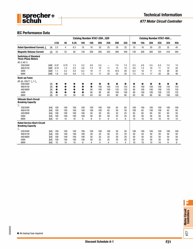
IEC Performance DataCatalog Number KTA7-25H...32H Catalog Number KTA7-45H...
2.5A 4A 6.3A 10A 16A 20A 25A 29A 32A 10A 16A 20A 25A 32A 45A
Rated Operational Current, Ie[A] 2.5 4 6.3 10 16 20 25 29 32 10 16 20 25 32 45
Magnetic Release Current [A] 33 52 82 130 208 260 325 406 448 130 208 260 325 416 585
Switching of StandardThree-Phase MotorsAC-2, AC-3
230/240V [kW] 0.37 0.75 1.5 2.2 4.0 5.5 ~ 7.5 7.5 2.2 4.0 5.5 6.3 7.5 13400/415V [kW] 0.75 1.5 2.2 4.0 7.5 10 11 13 15 4.0 7.5 10 11 15 22500V [kW] 1.1 2.2 3.0 6.3 10 11 15 18.5 20 6.3 10 11 15 20 30690V [kW] 1.8 3.0 4.0 7.5 13 17 22 25 25 7.5 13 17 22 30 40
Back-up FusesgG, gL, only if Icc ≥ Icu
230/240V [A] ➊ ➊ ➊ ➊ ➊ ➊ ➊ ➊ ➊ ➊ ➊ ➊ ➊ ➊ ➊
400/415V [A] ➊ ➊ ➊ ➊ ➊ 100 100 125 125 80 100 100 100 125 125440/460V [A] ➊ ➊ ➊ ➊ 80 100 100 125 125 80 100 100 100 125 125500V [A] ➊ ➊ ➊ ➊ 80 80 80 100 100 80 100 100 100 125 125690V [A] 20 35 50 50 63 63 63 80 80 63 80 80 80 100 100
Ultimate Short-CircuitBreaking CapacityIcu
230/240V [kA] 100 100 100 100 100 100 100 65 65 100 100 100 100 100 100400/415V [kA] 100 100 100 100 100 100 65 50 50 100 65 100 100 65 65440/460V [kA] 100 100 100 100 50 50 65 25 25 65 65 65 65 65 50500V [kA] 100 100 100 100 50 50 50 25 25 50 50 50 50 50 50690V [kA] 10 10 10 6 6 6 6 6 6 10 10 10 10 10 10
Rated Service Short-CircuitBreaking CapacityIcs
230/240V [kA] 100 100 100 100 100 100 100 50 50 100 100 100 100 100 100400/415V [kA] 100 100 100 100 50 25 50 25 25 50 50 50 50 50 50440/460V [kA] 100 100 100 100 50 25 25 20 20 50 50 50 50 50 50500V [kA] 100 100 100 100 50 25 25 20 20 50 50 50 50 50 50690V [kA] 10 10 10 6 4 4 4 4 4 10 10 10 10 6 6
F22
SSNA
9000
Mot
or C
ircui
t Co
ntro
llers
F
KT7
Discount Schedule A-1
Technical InformationKT7 Motor Circuit Controller
➊No backup fuse required.
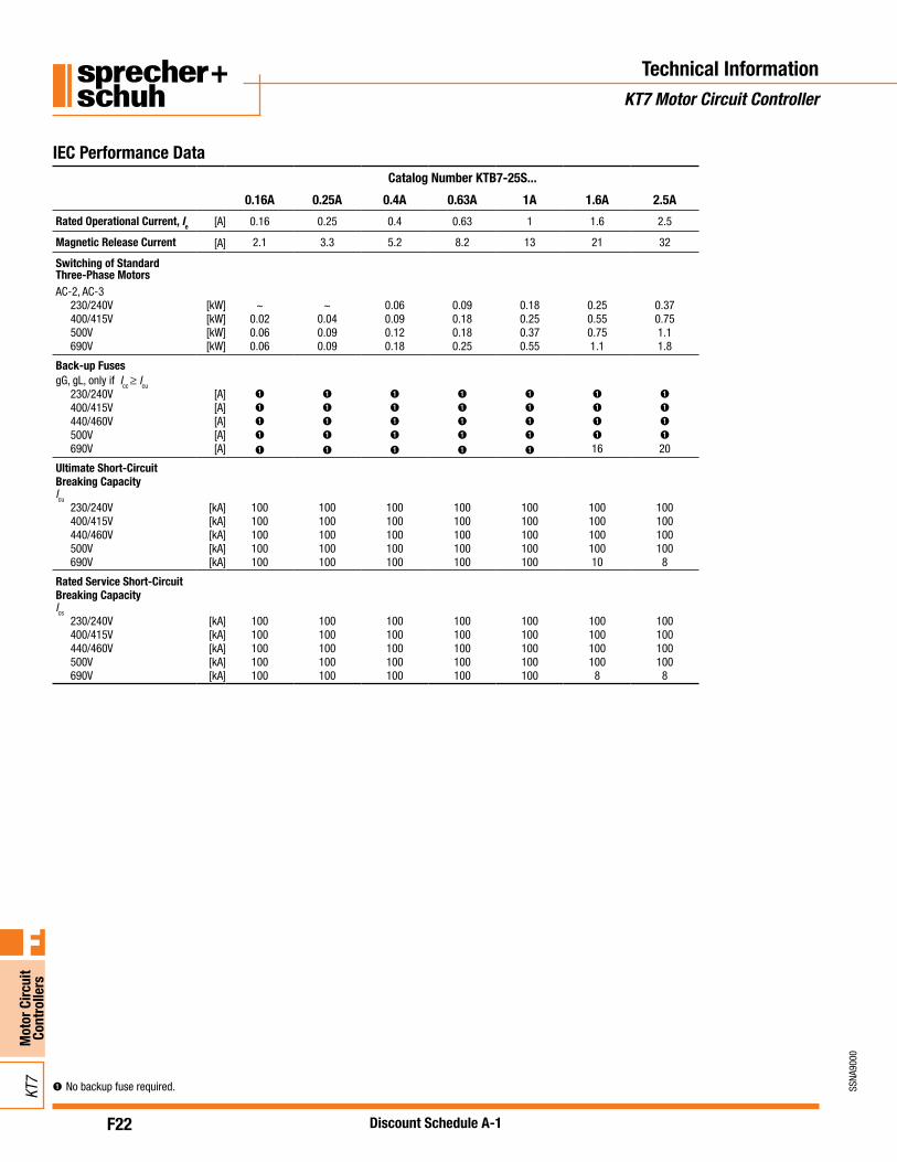
Catalog Number KTB7-25S...
0.16A 0.25A 0.4A 0.63A 1A 1.6A 2.5A
Rated Operational Current, Ie [A] 0.16 0.25 0.4 0.63 1 1.6 2.5
Magnetic Release Current [A] 2.1 3.3 5.2 8.2 13 21 32
Switching of StandardThree-Phase MotorsAC-2, AC-3
230/240V [kW] ~ ~ 0.06 0.09 0.18 0.25 0.37400/415V [kW] 0.02 0.04 0.09 0.18 0.25 0.55 0.75500V [kW] 0.06 0.09 0.12 0.18 0.37 0.75 1.1690V [kW] 0.06 0.09 0.18 0.25 0.55 1.1 1.8
Back-up FusesgG, gL, only if Icc ≥ Icu
230/240V [A] ➊ ➊ ➊ ➊ ➊ ➊ ➊400/415V [A] ➊ ➊ ➊ ➊ ➊ ➊ ➊440/460V [A] ➊ ➊ ➊ ➊ ➊ ➊ ➊500V [A] ➊ ➊ ➊ ➊ ➊ ➊ ➊690V [A] ➊ ➊ ➊ ➊ ➊ 16 20
Ultimate Short-CircuitBreaking CapacityIcu
230/240V [kA] 100 100 100 100 100 100 100400/415V [kA] 100 100 100 100 100 100 100440/460V [kA] 100 100 100 100 100 100 100500V [kA] 100 100 100 100 100 100 100690V [kA] 100 100 100 100 100 10 8
Rated Service Short-CircuitBreaking CapacityIcs
230/240V [kA] 100 100 100 100 100 100 100400/415V [kA] 100 100 100 100 100 100 100440/460V [kA] 100 100 100 100 100 100 100500V [kA] 100 100 100 100 100 100 100690V [kA] 100 100 100 100 100 8 8
IEC Performance Data

F23
SSNA
9000
Mot
or C
ircui
t Co
ntro
llers
F
KT7
Discount Schedule A-1
➊No backup fuse required.
Technical InformationKT7 Motor Circuit Controller
Catalog Number KTB7-25H...32H Catalog No. KTB7-45H...
2.5A 4A 6.3A 10A 16A 25A 32A 25A 32A 45A
Rated Operational Current, Ie [A] 2.5 4 6.3 10 16 25 32 25 32 45
Magnetic Release Current [A] 32 52 82 130 208 325 448 325 416 585
Switching of StandardThree-Phase MotorsAC-2, AC-3
230/240V [kW] 0.37 0.75 1.5 2.2 4.0 ~ 7.5 6.3 7.5 13400/415V [kW] 0.75 1.5 2.2 4.0 7.5 11 15 11 15 22500V [kW] 1.1 2.2 3.0 6.3 10 15 20 15 20 30690V [kW] 1.8 3.0 4.0 7.5 13 22 25 22 25 40
Back-up FusesgG, gL, only if Icc ≥ Icu
230/240V [A] ➊ ➊ ➊ ➊ ➊ ➊ ➊ 100 125 125400/415V [A] ➊ ➊ ➊ ➊ ➊ 100 125 100 125 125440/460V [A] ➊ ➊ ➊ ➊ 80 100 125 100 125 125500V [A] ➊ ➊ ➊ ➊ 80 80 100 100 125 125690V [A] 20 35 50 50 63 63 80 80 100 100
Ultimate Short-CircuitBreaking CapacityIcu
230/240V [kA] 100 100 100 100 100 100 65 100 100 100400/415V [kA] 100 100 100 100 100 65 50 100 65 65440/460V [kA] 100 100 100 100 50 50 25 65 65 50500V [kA] 100 100 100 10 50 25 25 50 50 50690V [kA] 10 10 10 6 6 6 6 10 10 10
Rated Service Short-CircuitBreaking CapacityIcs
230/240V [kA] 100 100 100 100 100 100 50 100 100 100400/415V [kA] 100 100 100 100 50 25 25 50 50 50440/460V [kA] 100 100 100 100 50 25 20 50 50 50500V [kA] 100 100 100 100 50 25 20 50 50 50690V [kA] 10 10 10 6 4 4 4 10 6 6
IEC Performance Data
F24
SSNA
9000
Mot
or C
ircui
t Co
ntro
llers
F
KT7
Discount Schedule A-1
Technical InformationKT7 Motor Circuit Controller
➊No backup fuse required.
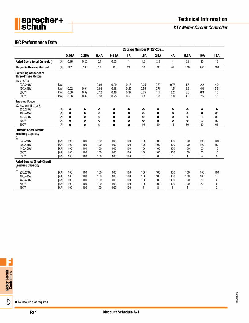
Catalog Number KTC7-25S...
0.16A 0.25A 0.4A 0.63A 1A 1.6A 2.5A 4A 6.3A 10A 16A
Rated Operational Current, Ie [A] 0.16 0.25 0.4 0.63 1 1.6 2.5 4 6.3 10 16
Magnetic Release Current [A] 3.2 5.2 8.2 13 21 33 52 82 130 208 260
Switching of StandardThree-Phase MotorsAC-2, AC-3
230/240V [kW] ~ ~ 0.06 0.09 0.18 0.25 0.37 0.75 1.5 2.2 4.0400/415V [kW] 0.02 0.04 0.09 0.18 0.25 0.55 0.75 1.5 2.2 4.0 7.5500V [kW] 0.06 0.09 0.12 0.18 0.37 0.75 1.1 2.2 3.0 6.3 10690V [kW] 0.06 0.09 0.18 0.25 0.55 1.1 1.8 3.0 4.0 7.5 13
Back-up FusesgG, gL, only if Icc ≥ Icu
230/240V [A] ➊ ➊ ➊ ➊ ➊ ➊ ➊ ➊ ➊ ➊ ➊
400/415V [A] ➊ ➊ ➊ ➊ ➊ ➊ ➊ ➊ ➊ ➊ 80440/460V [A] ➊ ➊ ➊ ➊ ➊ ➊ ➊ ➊ ➊ 63 80500V [A] ➊ ➊ ➊ ➊ ➊ ➊ ➊ ➊ ➊ 80 80690V [A] ➊ ➊ ➊ ➊ ➊ 16 20 35 50 50 63
Ultimate Short-CircuitBreaking CapacityIcu
230/240V [kA] 100 100 100 100 100 100 100 100 100 100 100400/415V [kA] 100 100 100 100 100 100 100 100 100 100 50440/460V [kA] 100 100 100 100 100 100 100 100 100 50 10500V [kA] 100 100 100 100 100 100 100 100 100 50 10690V [kA] 100 100 100 100 100 8 8 8 4 4 3
Rated Service Short-CircuitBreaking CapacityIcs
230/240V [kA] 100 100 100 100 100 100 100 100 100 100 100400/415V [kA] 100 100 100 100 100 100 100 100 100 100 15440/460V [kA] 100 100 100 100 100 100 100 100 100 50 6500V [kA] 100 100 100 100 100 100 100 100 100 50 6690V [kA] 100 100 100 100 100 8 8 8 4 4 3
IEC Performance Data
F25
SSNA
9000
Mot
or C
ircui
t Co
ntro
llers
F
KT7
Discount Schedule A-1
Technical InformationKT7 Motor Circuit Controller
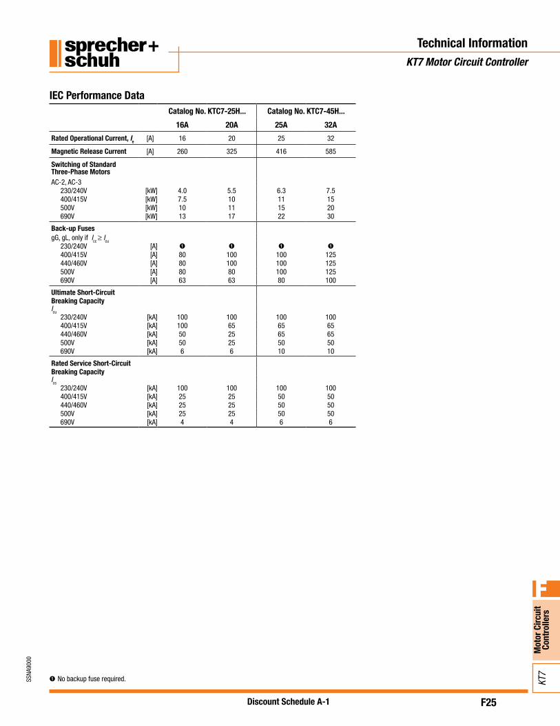
➊No backup fuse required.
Catalog No. KTC7-25H... Catalog No. KTC7-45H...
16A 20A 25A 32A
Rated Operational Current, Ie [A] 16 20 25 32
Magnetic Release Current [A] 260 325 416 585
Switching of StandardThree-Phase MotorsAC-2, AC-3
230/240V [kW] 4.0 5.5 6.3 7.5400/415V [kW] 7.5 10 11 15500V [kW] 10 11 15 20690V [kW] 13 17 22 30
Back-up FusesgG, gL, only if Icc ≥ Icu
230/240V [A] ➊ ➊ ➊ ➊400/415V [A] 80 100 100 125440/460V [A] 80 100 100 125500V [A] 80 80 100 125690V [A] 63 63 80 100
Ultimate Short-CircuitBreaking CapacityIcu
230/240V [kA] 100 100 100 100400/415V [kA] 100 65 65 65440/460V [kA] 50 25 65 65500V [kA] 50 25 50 50690V [kA] 6 6 10 10
Rated Service Short-CircuitBreaking CapacityIcs
230/240V [kA] 100 100 100 100400/415V [kA] 25 25 50 50440/460V [kA] 25 25 50 50500V [kA] 25 25 50 50690V [kA] 4 4 6 6
IEC Performance Data
F26
SSNA
9000
Mot
or C
ircui
t Co
ntro
llers
F
KT7
Discount Schedule A-1
Technical InformationKT7 Motor Circuit Controller
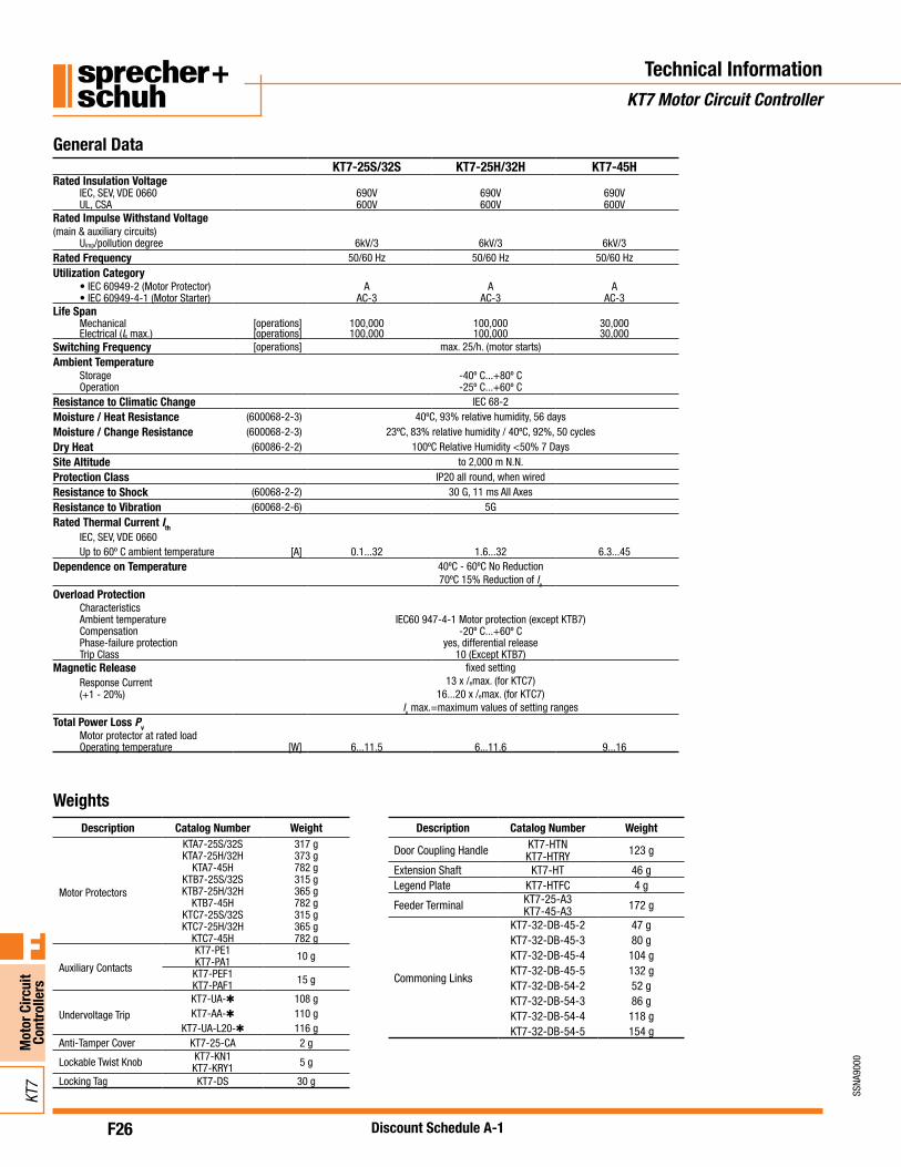
General DataKT7-25S/32S KT7-25H/32H KT7-45H
Rated Insulation VoltageIEC, SEV, VDE 0660 690V 690V 690VUL, CSA 600V 600V 600V
Rated Impulse Withstand Voltage(main & auxiliary circuits)
Uimp/pollution degree 6kV/3 6kV/3 6kV/3Rated Frequency 50/60 Hz 50/60 Hz 50/60 HzUtilization Category
• IEC 60949-2 (Motor Protector) A A A• IEC 60949-4-1 (Motor Starter) AC-3 AC-3 AC-3
Life SpanMechanical [operations] 100,000 100,000 30,000Electrical (Ie max.) [operations] 100,000 100,000 30,000
Switching Frequency [operations] max. 25/h. (motor starts)Ambient Temperature
Storage -40º C...+80º COperation -25º C...+60º C
Resistance to Climatic Change IEC 68-2Moisture / Heat Resistance (600068-2-3) 40ºC, 93% relative humidity, 56 daysMoisture / Change Resistance (600068-2-3) 23ºC, 83% relative humidity / 40ºC, 92%, 50 cyclesDry Heat (60086-2-2) 100ºC Relative Humidity <50% 7 DaysSite Altitude to 2,000 m N.N.Protection Class IP20 all round, when wiredResistance to Shock (60068-2-2) 30 G, 11 ms All AxesResistance to Vibration (60068-2-6) 5GRated Thermal Current Ith
IEC, SEV, VDE 0660Up to 60º C ambient temperature [A] 0.1...32 1.6...32 6.3...45
Dependence on Temperature 40ºC - 60ºC No Reduction70ºC 15% Reduction of Ie
Overload ProtectionCharacteristicsAmbient temperature IEC60 947-4-1 Motor protection (except KTB7)Compensation -20º C...+60º CPhase-failure protection yes, differential releaseTrip Class 10 (Except KTB7)
Magnetic Release fixed setting13 x /emax. (for KTC7)
16...20 x /emax. (for KTC7)Ie max.=maximum values of setting ranges
Response Current(+1 - 20%)
Total Power Loss PvMotor protector at rated loadOperating temperature [W] 6...11.5 6...11.6 9...16
WeightsDescription Catalog Number Weight
Motor Protectors
KTA7-25S/32S 317 gKTA7-25H/32H 373 g
KTA7-45H 782 gKTB7-25S/32S 315 gKTB7-25H/32H 365 g
KTB7-45H 782 gKTC7-25S/32S 315 gKTC7-25H/32H 365 g
KTC7-45H 782 g
Auxiliary Contacts
KT7-PE1 10 gKT7-PA1KT7-PEF1 15 gKT7-PAF1
Undervoltage Trip
KT7-UA-✱ 108 gKT7-AA-✱ 110 g
KT7-UA-L20-✱ 116 gAnti-Tamper Cover KT7-25-CA 2 g
Lockable Twist Knob KT7-KN1 5 gKT7-KRY1Locking Tag KT7-DS 30 g
Description Catalog Number Weight
Door Coupling Handle KT7-HTN 123 gKT7-HTRYExtension Shaft KT7-HT 46 gLegend Plate KT7-HTFC 4 g
Feeder Terminal KT7-25-A3 172 gKT7-45-A3
Commoning Links
KT7-32-DB-45-2 47 gKT7-32-DB-45-3 80 gKT7-32-DB-45-4 104 gKT7-32-DB-45-5 132 gKT7-32-DB-54-2 52 gKT7-32-DB-54-3 86 gKT7-32-DB-54-4 118 gKT7-32-DB-54-5 154 g
F27
SSNA
9000
Mot
or C
ircui
t Co
ntro
llers
F
KT7
Discount Schedule A-1
Auxiliary Contact Blocks forFront Mounting Catalog Number
KT7-PE1, KT7-PEF1
Auxiliary Contact Blocks forRight-Side Mounting Catalog Number
KT7-PA1, KT7-PAF1
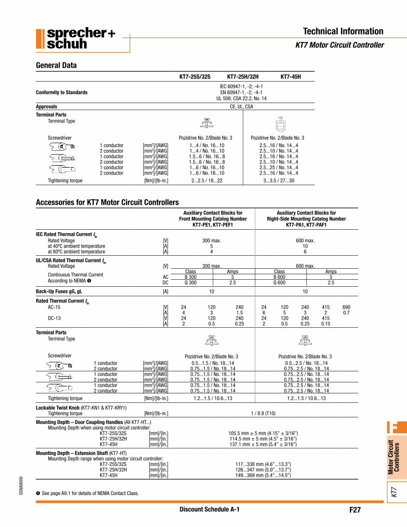
IEC Rated Thermal Current IthRated Voltage [V] 300 max. 600 max.at 40ºC ambient temperature [A] 5 10at 60ºC ambient temperature [A] 4 6
UL/CSA Rated Thermal Current IthRated Voltage [V] 300 max. 600 max.
Continuous Thermal Current According to NEMA ➊
Class Amps Class AmpsAC B 300 5 B 600 5DC Q 300 2.5 Q 600 2.5
Back-Up Fuses gG, gL [A] 10 10
Rated Thermal Current IthAC-15 [V] 24 120 240 24 120 240 415 690
[A] 4 3 1.5 6 5 3 2 0.7DC-13 [V] 24 120 240 24 120 240 415
[A] 2 0.5 0.25 2 0.5 0.25 0.15
Terminal Parts
Pozidrive No. 2/Blade No. 3 Pozidrive No. 2/Blade No. 3
Terminal Type
Screwdriver1 conductor [mm2]/[AWG] 0.5...1.5 / No. 18...14 0.5...2.5 / No. 18...142 conductor [mm2]/[AWG] 0.75...1.5 / No. 18...14 0.75...2.5 / No. 18...141 conductor [mm2]/[AWG] 0.75...1.5 / No. 18...14 0.75...2.5 / No. 18...142 conductor [mm2]/[AWG] 0.75...1.5 / No. 18...14 0.75...2.5 / No. 18...141 conductor [mm2]/[AWG] 0.75...1.5 / No. 18...14 0.75...2.5 / No. 18...142 conductor [mm2]/[AWG] 0.75...1.5 / No. 18...14 0.75...2.5 / No. 18...14
Tightening torque [Nm]/[lb-in.] 1.2...1.5 / 10.6...13 1.2...1.5 / 10.6...13
Lockable Twist Knob (KT7-KN1 & KT7-KRY1)Tightening torque [Nm]/[lb-in.] 1 / 8.8 (T10)
Mounting Depth – Door Coupling Handles (All KT7-HT...)Mounting Depth when using motor circuit controller:
KT7-25S/32S [mm]/[in.] 105.5 mm ± 5 mm (4.15” ± 3/16”)KT7-25H/32H [mm]/[in.] 114.5 mm ± 5 mm (4.5” ± 3/16”)KT7-45H [mm]/[in.] 137.1 mm ± 5 mm (5.4” ± 3/16”)
Mounting Depth – Extension Shaft (KT7-HT)Mounting Depth range when using motor circuit controller:
KT7-25S/32S [mm]/[in.] 117...338 mm (4.6”...13.3”)KT7-25H/32H [mm]/[in.] 126...347 mm (5.0”...13.7”)KT7-45H [mm]/[in.] 149...369 mm (5.4”...14.5”)
Technical InformationKT7 Motor Circuit Controller
General Data
Accessories for KT7 Motor Circuit Controllers
KT7-25S/32S KT7-25H/32H KT7-45H
Conformity to StandardsIEC 60947-1, -2; -4-1EN 60947-1, -2; -4-1
UL 508; CSA 22.2, No. 14
Approvals CE, UL, CSA
Terminal PartsTerminal Type
Screwdriver Pozidrive No. 2/Blade No. 3 Pozidrive No. 2/Blade No. 31 conductor [mm2]/[AWG] 1...4 / No. 16...10 2.5...16 / No. 14...42 conductor [mm2]/[AWG] 1...4 / No. 16...10 2.5...10 / No. 14...41 conductor [mm2]/[AWG] 1.5...6 / No. 16...8 2.5...16 / No. 14...42 conductor [mm2]/[AWG] 1.5...6 / No. 16...8 2.5...10 / No. 14...41 conductor [mm2]/[AWG] 1...6 / No. 16...10 2.5...25 / No. 14...42 conductor [mm2]/[AWG] 1...6 / No. 16...10 2.5...16 / No. 14...4
Tightening torque [Nm]/[lb-in.] 2...2.5 / 18...22 3...3.5 / 27...30
➊See page A9.1 for details of NEMA Contact Class.

F28
SSNA
9000
Mot
or C
ircui
t Co
ntro
llers
F
KT7
Discount Schedule A-1
Undervoltage Trip for Left-Side Mounting
Cat. Number KT7-UA-*
Undervoltage Trip with2 Auxiliary Contacts for
Left-Side MountingCat. Number KT7-UA-L20-*
Shunt Trip forLeft-Side Mounting
Cat. Number KT7-AA-*
Actuating Voltage Pull-in 0.85...1.1 x Us 0.85...1.1 x Us 0.7...1.1 x UsDrop-out 0.7...0.35 x Us 0.7...0.35 x Us
Rated Control Voltage minimum 21V 50 Hz, 24V 60 Hz 21V 50 Hz, 24V 60 Hz 21V 50 Hz, 24V 60 Hzmaximum 600V 50 Hz 600V 50 Hz 600V 50 Hz
On-Time 100% 100% 100%
Coil Rating Pull-in 8.5 VA, 6 W 8.5 VA, 6 W 8.5 VA, 6 WHold 3 VA, 1.2 W 3 VA, 1.2 W 3 VA, 1.2 W
Terminal PartsTerminal Type
Pozidrive No. 2/Blade No. 3Screwdriver1 coNductor [mm2]/[aWG] 0.5...2.5 / No. 18...142 coNductor [mm2]/[aWG] 0.75...2.5 / No. 18...141 coNductor [mm2]/[aWG] 0.75...2.5 / No. 18...142 coNductor [mm2]/[aWG] 0.75...2.5 / No. 18...141 coNductor [mm2]/[aWG] 0.75...2.5 / No. 18...142 coNductor [mm2]/[aWG] 0.75...2.5 / No. 18...14
Tightening torque [Nm]/[lb-in.] 1.2...1.5 / 10.6...13.3
Feeder BlockKT7-25-A2E
Feeder TerminalKT7-32-A3E
Compact BusbarKT7-32-DB...
Feeder TerminalKT7-45-A3E
Compact BusbarKT7-45-DB...
Rated Thermal Current Ith [V] 600 600 600 600 600at 60º C ambient temperature [A] 64 64 64 120 120
1 conductor [mm2]/[AWG] 4...25/No. 10...4 2.5...25/No. 14...4 ~ 4...50/12...1/0 ~
1 conductor [mm2]/[AWG] 4...25/No. 10...4 2.5...25/No. 14...4 ~ 2.5...50/12...1/0 ~
1 conductor [mm2]/[AWG] 2.5...25/No. 14...4 2.5...25/No. 14...4 ~ 2.5...50/12...1/0 ~
Tightening torque [Nm]/[lb-in.] 3...3.5 / 27...31 3...3.5 / 27...31 ~ 5...6/45...54 ~
Technical InformationKT7 Motor Circuit Controller/KF7 Fuse Holders
KT7 Accessories
KF7 Fuse Holder Accessories KF7 Fuse Holder
Rated Thermal Current Ith [V] 600
at 60º C ambient temperature [A] 30
Short Circuit
Withstand [KA] 200
Uimp [KV] 6
Terminal Parts
Terminal Type
ScrewdriverPozidrive No. 2/Blade
No. 3
1 conductor [mm2]/[AWG] 1.0…4 / 16…10
1 conductor [mm2]/[AWG] 1.0…4 / 16…10
Tightening torque [Nm]/[lb-in.] 1.7 / 15

F29
SSNA
9000
Mot
or C
ircui
t Co
ntro
llers
F
KT7
Discount Schedule A-1
Time-Current CharacteristicKT7 Manual Motor Starter/Protector
Technical InformationKT7 Motor Circuit Controller
1. Thermal Release Trip Current The adjustable current-dependent delayed bimetal release protects motors against overload. The curve shows the mean operating current at an ambient temperature of 20°C starting from the cold state. Careful testing and setting ensures effective motor protection even in the case of single-phasing. The overload characteristic is also valid for transformer protection.
2. Magnetic Release Trip Current The instantaneous magnetic trip has a fixed operating current setting. This
corresponds to 13 times the maximum value of setting range (high inrush protection -20 x Ie maximum). At a lower overload setting the magnetic trip is correspondingly higher.
Current Setting Ief
The overload trip corresponds to a thermal overload relay in a motor starter conforming to IEC 947-4-1. If a different value is prescribed (e.g., reduced Ie for cooling medium having a temperature higher than 40°C or a place of installation higher than 2000 m above sea level), the setting current is equal to the reduced rated current Ie of the motor.
F30
SSNA
9000
Mot
or C
ircui
t Co
ntro
llers
F
KT7
Discount Schedule A-1
Technical InformationKT7 Motor Circuit Controller
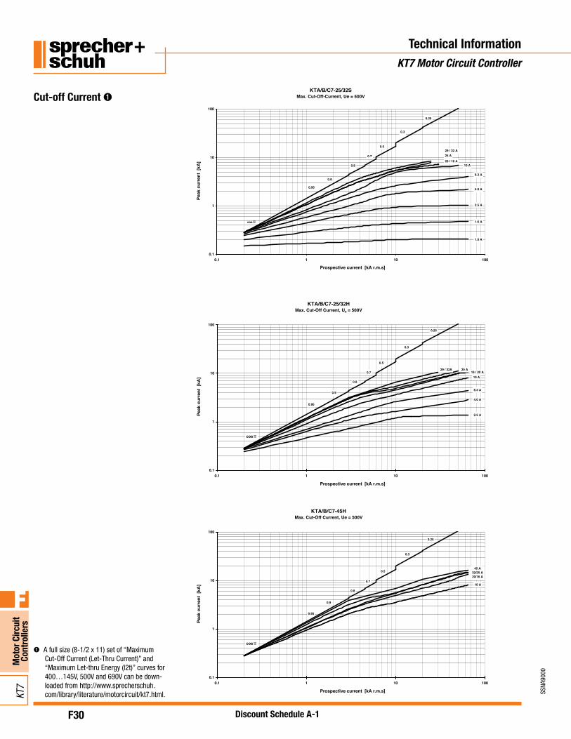
Cut-off Current ➊KTA/B/C7-25/32S
Max. Cut-Off-Current, Ue = 500V
0.1
1
10
100
0.1 1 10 100
Prospective current [kA r.m.s]
Peak
cur
rent
[kA
]
0.25
0.3
0.5
0.7
0.8
0.9
0.95
cos �
4.0 A
2.5 A
1.6 A
1.0 A
6.3 A
10 A20 / 16 A
25 A29 / 32 A
KTA/B/C7-25/32HMax. Cut-Off Current, Ue = 500V
0.1
1
10
100
0.1 1 10 100
Prospective current [kA r.m.s]
Peak
cur
rent
[kA
]
0.25
0.3
0.5
0.7
0.8
0.9
0.95
cos �
4.0 A
2.5 A
6.3 A
10 A16 / 20 A
25 A29 / 32A
KTA/B/C7-45HMax. Cut-Off Current, Ue = 500V
0.1
1
10
100
0.1 1 10 100
Prospective current [kA r.m.s]
Peak
cur
rent
[kA
]
0.25
0.3
0.5
0.7
0.8
0.9
0.95
cos �
10 A
45 A32/25 A20/16 A
➊ A full size (8-1/2 x 11) set of “Maximum Cut-Off Current (Let-Thru Current)” and “Maximum Let-thru Energy (l2t)” curves for 400…145V, 500V and 690V can be down-loaded from http://www.sprecherschuh.com/library/literature/motorcircuit/kt7.html.
F30.1
SSNA
9000
Mot
or C
ircui
t Co
ntro
llers
F
KT7
Discount Schedule A-1
Technical InformationKT7 Motor Circuit Controller
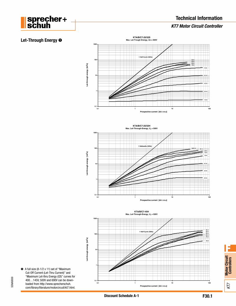
Let-Through Energy ➊KTA/B/C7-25/32S
Max. Let-Trough Energy, Ue = 500V
0.1
1
10
100
1000
0.1 1 10 100
Prospective current [kA r.m.s]
Let-t
hrou
gh e
nerg
y [k
A2 s]
10 A
6.3 A
4.0 A
2.5 A
1.6 A
32 A25 A20 A16 A
1 Half-Cycle (50Hz)
KTA/B/C7-25/32HMax. Let-Through-Energy, Ue = 500V
0.1
1
10
100
1000
0.1 1 10 100
Prospective current [kA r.m.s]
Let-t
hrou
gh e
nerg
y [
kA2 s]
1 Halbwelle (50Hz)
10 A
6.3 A
4.0 A
2.5 A
25 A20 A16 A
29/32 A
KTA/B/C7-45HMax. Let-Through-Energy, Ue = 500V
0.1
1
10
100
1000
0.1 1 10 100
Prospective current [kA r.m.s]
Let-t
hrou
gh e
nerg
y [k
A2 s]
1 Half-Cycle (50Hz)
10 A
45 A32 A25 A20 A16 A
➊ A full size (8-1/2 x 11) set of “Maximum Cut-Off Current (Let-Thru Current)” and “Maximum Let-thru Energy (l2t)” curves for 400…145V, 500V and 690V can be down-loaded from http://www.sprecherschuh.com/library/literature/motorcircuit/kt7.html.

F31
SSNA
9000
Mot
or C
ircui
t Co
ntro
llers
F
KT7
Discount Schedule A-1
Wiring DiagramsKF7 with KT7 Motor Circuit Controller
KF7 Fuse Holder used with CA7 Contactor
KF7 Fuse Holder
CA7Contactor
KF7-PE1-11(late make/early break)
KF7 Fuse Holder used with KTA7 Motor Circuit Controller and CA7 Contactor
KF7 KTA7
Motor Circuit ControllerFuse Holder
CA7Contactor
KF7-PE1-11(late make/early break)
F32
SSNA
9000
Mot
or C
ircui
t Co
ntro
llers
F
KT7
Discount Schedule A-1
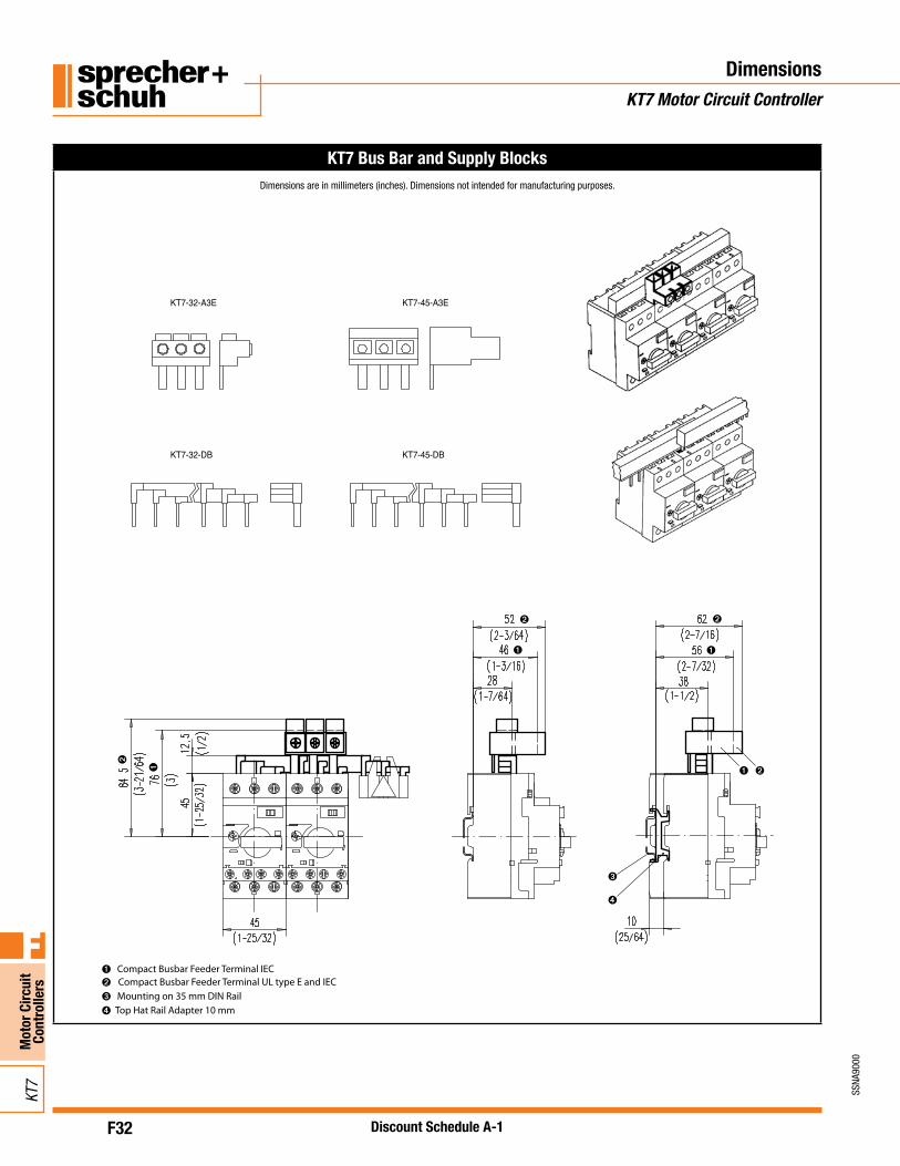
KT7 Bus Bar and Supply Blocks
Compact Busbar Feeder Terminal IEC Compact Busbar Feeder Terminal UL type E and IEC Mounting on 35 mm DIN Rail Top Hat Rail Adapter 10 mm
➊➋
➌
➍
➊ ➊
➊ ➊
➋
➋ ➋
➋
➌
➍
KT7-32-A3E KT7-45-A3E
KT7-32-DB KT7-45-DB
DimensionsKT7 Motor Circuit Controller
Dimensions are in millimeters (inches). Dimensions not intended for manufacturing purposes.

F33
SSNA
9000
Mot
or C
ircui
t Co
ntro
llers
F
KT7
Discount Schedule A-1
DimensionsKT7 Motor Circuit Controller
KT_7-25/32 Motor Circuit Controllers (withTerminal Adaptor KT7-25-TE1)
KT_7-45H Motor Circuit Controllers (with Terminal Adaptor KT7-45-TE)
KT_7-45H Motor Circuit Controllers (without Terminal Adaptor KT7-45-TE)
Mounting on 35 mm DIN Rail Undervoltage/shunt trip Auxiliary contact (front mounted)Auxiliary contact (side mounted)
➊➋
➌
➍
➊
➋
➋
➌
➌
➍ ➍➍
➍
111.
4(4
-25/
64)
Dimensions are in millimeters (inches). Dimensions not intended for manufacturing purposes.
KT_7-25S/32S KT_7-25H/32H
KT_7-45H
95(3
-61/
64)
85(3
-9/1
6)
95(3
-61/
64)
85(3
-9/1
6)
119.
3(4
-11/
16)
111.
4(4
-25/
64)
KT_7-25S/32S KT_7-25H/32H
KT_7-45H
95(3
-61/
64)
85(3
-9/1
6)
95(3
-61/
64)
85(3
-9/1
6)
119.
3(4
-11/
16)
111.
4(4
-25/
64)
F34
SSNA
9000
Mot
or C
ircui
t Co
ntro
llers
F
KT7
Discount Schedule A-1
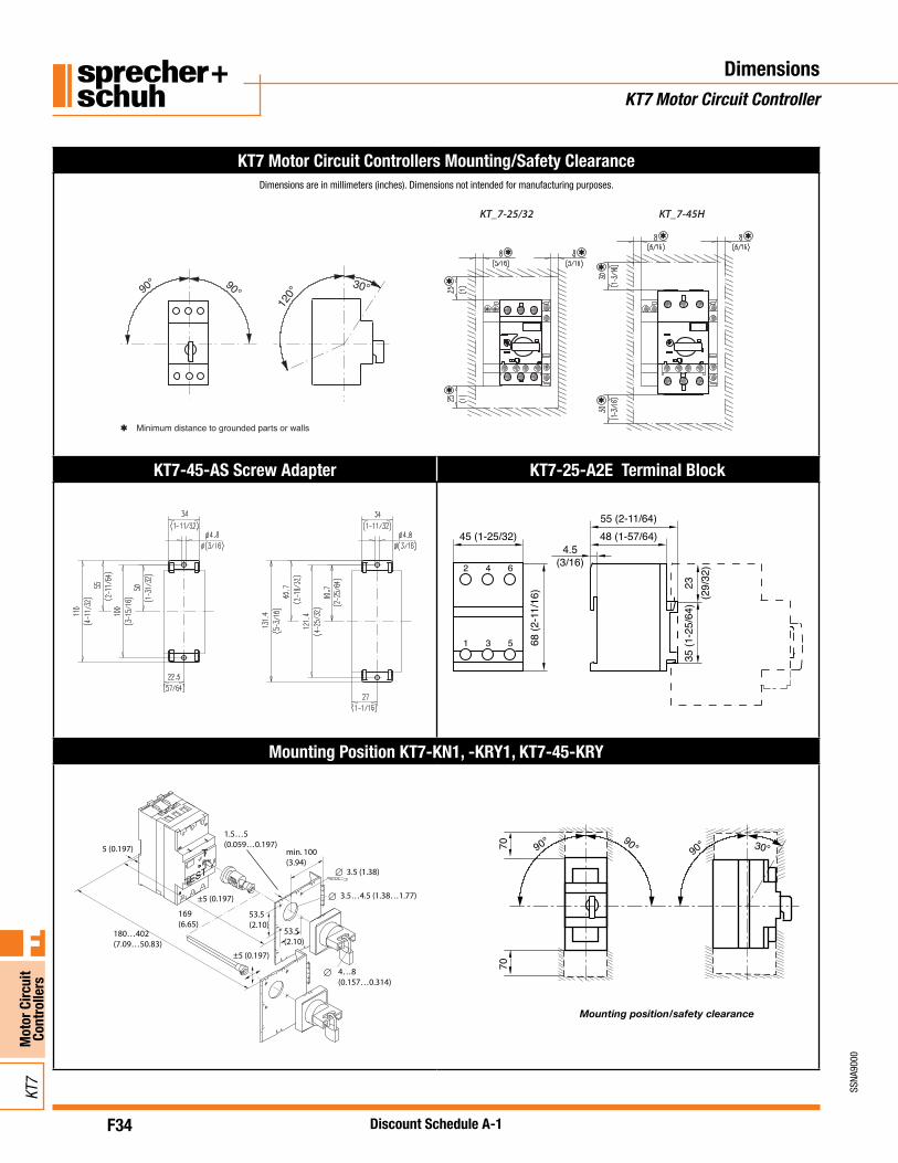
KT7 Motor Circuit Controllers Mounting/Safety Clearance
Minimum distance to grounded parts or walls
90° 90°12
0°30°
KT_7-25/32 KT_7-45H
Mounting position/safety clearance of Cat. No. 140M-C…, 140M-D…, 140M-F…KT7-45-AS Screw Adapter KT7-25-A2E Terminal Block
. .
.
Screw Adapter 140M-C-N45 for 140M-C2/D8 and 140M-F8
Mounting Position KT7-KN1, -KRY1, KT7-45-KRY
Mounting position/safety clearance
90° 30°7070
90° 90°5 (0.197)
±5 (0.197)
±5 (0.197)
180…402(7.09…50.83)
169(6.65)
53.5(2.10)
53.5(2.10)
4…8(0.157…0.314)
1.5…5(0.059…0.197)
min. 100(3.94)
3.5 (1.38)
3.5…4.5 (1.38…1.77)
DimensionsKT7 Motor Circuit Controller
Dimensions are in millimeters (inches). Dimensions not intended for manufacturing purposes.
F35
SSNA
9000
Mot
or C
ircui
t Co
ntro
llers
F
KT7
Discount Schedule A-1
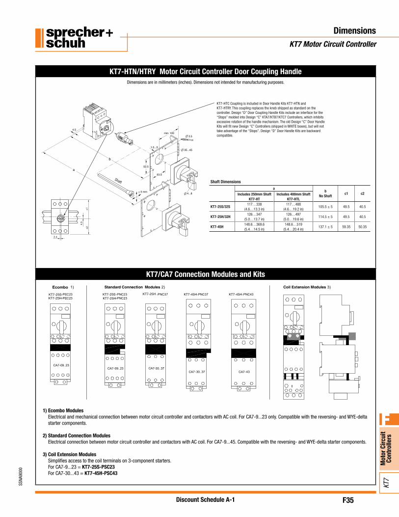
DimensionsKT7 Motor Circuit Controller
Dimensions are in millimeters (inches). Dimensions not intended for manufacturing purposes.
KT7-HTN/HTRY Motor Circuit Controller Door Coupling Handle
KT7-HTC Coupling is included in Door Handle Kits KT7-HTN and KT7-HTRY. This coupling replaces the knob shipped as standard on the controller. Design “D” Door Coupling Handle Kits include an interface for the “Stops” molded into Design “C” KTA7/KTB7/KTC7 Controllers, which inhibits excessive rotation of the handle mechanism. The old Design “C” Door Handle Kits will fit new Design “C” Controllers (shipped in WHITE boxes), but will not take advantage of the “Stops”. Design “D” Door Handle Kits are backward compatible.
ab
No Shaftc1 c2Includes 250mm Shaft
KT7-HTIncludes 400mm Shaft
KT7-HTL
KT7-25S/32S117…338
(4.6…13.3 in)117…488
(4.6…19.2 in)105.5 ± 5 49.5 40.5
KT7-25H/32H126…347
(5.0…13.7 in)126…497
(5.0…19.6 in)114.5 ± 5 49.5 40.5
KT7-45H148.6…369.6(5.4…14.5 in)
148.6…519(5.4…20.4 in)
137.1 ± 5 59.35 50.35
Shaft Shaft Dimensions
KT7/CA7 Connection Modules and Kits
1) Ecombo ModulesElectrical and mechanical connection between motor circuit controller and contactors with AC coil. For CA7-9...23 only. Compatible with the reversing- and WYE-delta starter components.
2) Standard Connection ModulesElectrical connection between motor circuit controller and contactors with AC coil. For CA7-9...45. Compatible with the reversing- and WYE-delta starter components.
3) Coil Extension ModulesSimplifies access to the coil terminals on 3-component starters. For CA7-9...23 = KT7-25S-PSC23For CA7-30...43 = KT7-45H-PSC43
F36
SSNA
9000
Mot
or C
ircui
t Co
ntro
llers
F
KT7
Discount Schedule A-1
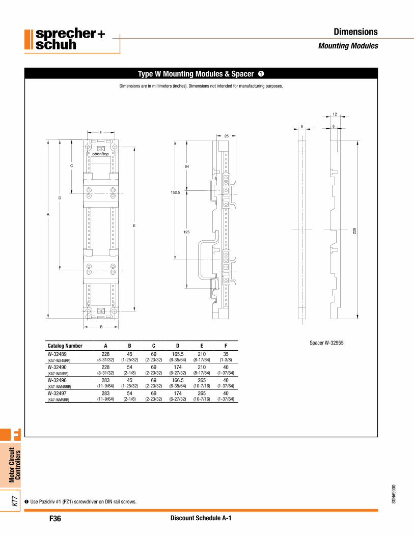
DimensionsMounting Modules
8
12
228
9
Type W Mounting Modules & Spacer ➊
Catalog Number A B C D E F
W-32489(KA7-WS45RR)
228(8-31/32)
45(1-25/32)
69(2-23/32)
165.5 (6-35/64)
210(8-17/64)
35(1-3/8)
W-32490(KA7-WS5RR)
228(8-31/32)
54(2-1/8)
69(2-23/32)
174(6-27/32)
210(8-17/64)
40(1-37/64)
W-32496(KA7-WM45RR)
283(11-9/64)
45(1-25/32)
69(2-23/32)
166.5(6-35/64)
265(10-7/16)
40(1-37/64)
W-32497(KA7-WM5RR)
283(11-9/64)
54(2-1/8)
69(2-23/32)
174(6-27/32)
265(10-7/16)
40(1-37/64)
Spacer W-32955
Dimensions are in millimeters (inches). Dimensions not intended for manufacturing purposes.
➊Use Pozidriv #1 (PZ1) screwdriver on DIN rail screws.

F36.1
SSNA
9000
Mot
or C
ircui
t Co
ntro
llers
F
KT7
Discount Schedule A-1
KF7
Dimensions & Wiring DiagramKF7 Fuse Holders
KF7 Fuse Holders Dimensions
1
F1
K1
3 52715
16 28
A1
A2
2 4 6
2 4 6
1 3 5
(2.27)57.7
(3.54)89.9
(0.18)4.5
(1.91)48.5
(2.82)71.5
(2.85)72.4
(0.10)2.5 (1.00)
25.3
(1.66)42.1
(0.61)15.5
(0.30)7.5
(2.58)65.5
(1.23)31.2
(1.77)45
KF7 Fuse Holders Wiring Diagram (IEC)
1
F1
K1
3 52715
16 28
A1
A2
2 4 6
2 4 6
1 3 5
(2.27)57.7
(3.54)89.9
(0.18)4.5
(1.91)48.5
(2.82)71.5
(2.85)72.4
(0.10)2.5 (1.00)
25.3
(1.66)42.1
(0.61)15.5
(0.30)7.5
(2.58)65.5
(1.23)31.2
(1.77)45
Dimensions are in millimeters (inches). Dimensions not intended for manufacturing purposes.


![Catalog Number KTA7-25S.. - Sprecher + Schuh500V [kW] 0.06 0.09 0.12 0.18 0.37 0.75 1.1 2.2 3.0 6.3 10 690V [kW] 0.06 0.09 0.18 0.25 0.55 1.1 1.8 3.0 4.0 7.5 13 Back-up Fuses gG, gL,](https://static.fdocuments.net/doc/165x107/5fe0b511ac0cd220d353b443/catalog-number-kta7-25s-sprecher-schuh-500v-kw-006-009-012-018-037.jpg)


![Transient Recovery VoltageResultados Tipo de falla TRV [kV] RRRV [kV/us] J12/J13 Barra 3f 262,56 5,1 J12/J13 ATR 3f 404,94 8,7 KT7 Barra 2f 385,57 4,6 KT7 ATR 3f 944,92 11,9 Tercer](https://static.fdocuments.net/doc/165x107/5f62304b9cb2893ed84565ba/transient-recovery-resultados-tipo-de-falla-trv-kv-rrrv-kvus-j12j13-barra.jpg)


