Catalog đèn báo nút nhấn phi 30 (Dòng chống cháy)
13
1 30mm Hazardous Location Switches: EU2B Series STANDARDS COMPLIANCE Switches Pilot Lights Meters UL Class I, Zone 1, AEx de IIC T6 Gb Class I, Div 2, Groups A, B, C and D Class I, Zone 1, AEx de IIC T6 Gb Class I, Div 2, Groups A, B, C and D Class I, Zone 1, AEx de IIC T6 Gb Class I, Div 2, Groups A, B, C and D c-UL Class I, Zone 1, Ex de IIC T6 Gb Class I, Div 2, Groups A, B, C and D Class I, Zone 1, Ex de IIB T6 Gb Class I, Div 2, Groups C and D Class I, Zone 1, Ex de IIC T6 Gb Class I, Div 2, Groups A, B, C and D ATEX II2G Ex de IIC II2D tD A21 IP65 II2G Ex de IIC Gb II2D Ex tb IIIC Db IP65 CERTIFICATE NUMBERS UL/cUL E347230 ATEX PTB 08 ATEX 1053 U PTB 08 ATEX 1003 U APPLICABLE STANDARDS Products Applicable Standards Mark Certifications Pushbuttons Selector Switches Key Selector Switches Pilot Lights EN60947-5-1 EU Low Voltage Directive Emergency Stop Switch EN60947-5-5 TÜV SÜD EU Low Voltage Directive PRODUCT DESCRIPTION Complying with UL and ATEX Directives for hazardous environments, new 30mm EU2B Hazardous Location Switches provide increased safety for your applications. Available models include: • Pushbutton Switches • Pilot Lights • Selector Switches • Key Selector Switches • Emergency Stop Switches • Meters KEY FEATURES • Class I, Zone 1/Division 2 • Applicable in explosive gas atmospheres (AEx de IIC T6 Gb) • UL Type 4X rated • Up to 3 contact blocks • Selector switches available with lever or key • Selector switches available with overlapping contacts • Exposed and finger-safe (IP20) screw terminals available IECEx is pending approval
-
Upload
cty-tnhh-hao-phuong -
Category
Engineering
-
view
550 -
download
2
Transcript of Catalog đèn báo nút nhấn phi 30 (Dòng chống cháy)

1
30mm Hazardous Location Switches: EU2B Series
STANDARDS COMPLIANCE
Switches Pilot Lights Meters
UL Class I, Zone 1, AEx de IIC T6 GbClass I, Div 2, Groups A, B, C and D
Class I, Zone 1, AEx de IIC T6 GbClass I, Div 2, Groups A, B, C and D
Class I, Zone 1, AEx de IIC T6 GbClass I, Div 2, Groups A, B, C and D
c-UL Class I, Zone 1, Ex de IIC T6 GbClass I, Div 2, Groups A, B, C and D
Class I, Zone 1, Ex de IIB T6 GbClass I, Div 2, Groups C and D
Class I, Zone 1, Ex de IIC T6 GbClass I, Div 2, Groups A, B, C and D
ATEXII2G Ex de IIC
II2D tD A21 IP65
II2G Ex de IIC Gb
II2D Ex tb IIIC Db IP65
CERTIFICATE NUMBERS
UL/cUL E347230
ATEX PTB 08 ATEX 1053 UPTB 08 ATEX 1003 U
APPLICABLE STANDARDS
Products Applicable Standards Mark Certifications
PushbuttonsSelector SwitchesKey Selector SwitchesPilot Lights
EN60947-5-1 EU Low Voltage Directive
Emergency Stop Switch EN60947-5-5
TÜV SÜD
EU Low Voltage Directive
PRODUCT DESCRIPTION
Complying with UL and ATEX Directives for hazardous environments, new 30mm EU2B Hazardous Location Switches provide increased safety for your applications.
Available models include:
• Pushbutton Switches
• Pilot Lights
• Selector Switches
• Key Selector Switches
• Emergency Stop Switches
• Meters
KEY FEATURES
• Class I, Zone 1/Division 2
• Applicable in explosive gas atmospheres (AEx de IIC T6 Gb)
• UL Type 4X rated
• Up to 3 contact blocks
• Selector switches available with lever or key
• Selector switches available with overlapping contacts
• Exposed and finger-safe (IP20) screw terminals available
IECEx is pending approval

2
SPECIFICATIONS
General SpecificationsDegree of Protection IP65 (IEC60529), Type 4XInsulation Resistance 100 MΩ minimum (500V DC megger)Operating Temperature −20 to +50°C (no freezing)Operating Humidity 45 to 85% (no condensation)Altitude 2,000m MaximumPollution Degree 3
Shock ResistanceOperating Extremes
100 m/s² Emergency Stop Switch: 150 m/s²(without meter)
Damage Limits 1000 m/s²
Vibration Resistance
Operating Extremes
5 to 55 Hz, amplitude 0.5 mm Emergency Stop Switch:5 to 500 Hz, amplitude 0.35mm, acceleration 50 m/s² (Without Meter)
Damage Limits
30Hz, amplitude 1.5mm Emergency Stop Switch:5 to 500 Hz, amplitude 0.35 mm, acceleration 50 m/s²
Switches
Rated Insulation Voltage 600VContact Resistance 50mΩ maximum (initial value)Impulse Withstand Voltage (Uimp) 6kVInsulation Resistance 100MΩ minimum (500V DC megger)
Short-Circuit Protection 250V/10A fuse(Type aM IEC60269-1/IEC60269-2)
Conditional Short-Circuit Current 1,000A
Mechanical Life
Pushbutton 1,000,000 operations minimumSelector Switch 500,000 operations minimumKey Selector Switch 500,000 operations minimumEmergency Stop Switch 50,000 operations minimum
Electrical Life
Pushbutton 250,000 (switching frequency 1800 operations/h)
Selector Switch 250,000 (switching frequency 900 operations/h)
Key Selector Switch 250,000 (switching frequency 900 operations/h)
Emergency Stop Switch 50,000 (switching frequency 900 operations/h)
Minimum Operator Stroke Required for Direct Opening Action
Emergency Stop Switch 7.0mm
Maximum Operator Stroke Emergency Stop Switch 9.0mm
* Contact bounce Contacts will bounce during operation of pushbuttons and selector switches (reference value: 20 ms). Be sure to take contact bounce time into consideration when designing a control circuit. Contact Ratings (Switches)
Contact Rating
Rated Insulation Voltage (Ui) 600VRated Thermal Current (Ith) 10A*Rated Operating Voltage (Ue) 24V 120V 240V 500V
Rated Operat-ing Current (Ie)
AC50/60Hz
Resistive Load (AC12) 10A* 10A* 6A 2.8AInductive Load (AC15) 10A* 6A 3A 1.4A
DCResistive Load (DC12) 8A 2.2A 1.1A —Inductive Load (DC13) 4A 1.1A 0.55A —
*Up to 2 contacts (per control unit): 10A 3 contacts (per control unit): 9AMinimum applicable load: 3V AC/DC, 5mAApplicable operating locations may vary according to operating conditions and load types.
Contact Rating Code Designation
Thermal Continuous Test Current Amperes
Maximum current, Amperes Maximum Volt-Amperes
120 Volt 240 Volt 480 Volt 600 Volt 600 Volt
Make Break Make Break Make Break Make Break Make Break
A600 10 60 6.00 30 3.00 15 1.5 12 1.2 7200 720
Pilot Lights
Rated Insulation Voltage (Ui) 500V
Rated Operating Voltage (Ue)Voltage 6V, 12V, 24V AC/DCTransformer 120V, 230V, 240V, 380V, 480V AC
Impulse Withstand Voltage (Uimp) 4kVInsulation Resistance 100 MΩ minimum (500V DC)Frequency 50/60Hz
Power Consumption (approx.)Full Voltage 0.3WTransformer 1.5VA
Life (reference value) Approx. 40,000 hours* Because the built-in LED lamp is a high brightness version, the lamp may light dimly due to induction even when power is off.
Meters
Accuracy Class 2.5
Insulation Resistance 100 MΩ minimum (500V DC megger)
AC
am
met
er
Rated Insulation Voltage (Ui) 300VOperation Moving coreImpulse Withstand Voltage (Uimp) 4kVPower Consumption 1VAMeasurement 5A, 10A, 30A, 50A, etcInput (CT Ratio) 1A, 5AExtended Memory 3 times, etc
DC
am
met
er
Rated Insulation Voltage (Ui) 150VOperation Moving coilImpulse Withstand Voltage (Uimp) 2.5kVInput 0 to10V DC, 4 to 20mA, etc.Power Consumption 0.15WConsumption Current 1mA
*Use a commercially available CT (current transformer) for all AC ammeters, and install the CT in a non-hazardous location.

3
PART NUMBERS
Pushbuttons
Note: Use only when interpreting part numbers. Do not use for developing part numbers.
Part Number Style andFunction
Contact Arrangement
Weight (Approx.) ➀ Button Color
EU2B-YB110➃➀➁
Flush Momentary
1NO68g
➀ Blank - supplied with red, green, black, and white buttons
For yellow or blue buttons, specify Y (yellow) or S (blue).
EU2B-YB101➃➀➁ 1NC
EU2B-YB111➃➀➁ 1NO-1NC
92gEU2B-YB120➃➀➁ 2NO
EU2B-YB102➃➀➁ 2NC
EU2B-YB121➃➀➁ 2NO-1NC
116gEU2B-YB112➃➀➁ 1NO-2NC
EU2B-YB130➃➀➁ 3NO
EU2B-YB103➃➀➁ 3NC
EU2B-YB210➃➀➁
Extended Momentary
1NO70g
Specify a button color code in place of ➀ in the part number
B : blackG : greenR : redS : blueW : whiteY : yellow
EU2B-YB201➃➀➁ 1NC
EU2B-YB211➃➀➁ 1NO-1NC
94gEU2B-YB220➃➀➁ 2NO
EU2B-YB202➃➀➁ 2NC
EU2B-YB221➃➀➁ 2NO-1NC
118gEU2B-YB212➃➀➁ 1NO-2NC
EU2B-YB230➃➀➁ 3NO
EU2B-YB203➃➀➁ 3NC
EU2B-YB310➃➀➁
MushroomMomentary
1NO76g
EU2B-YB301➃➀➁ 1NC
EU2B-YB311➃➀➁ 1NO-1NC
101gEU2B-YB320➃➀➁ 2NO
EU2B-YB302➃➀➁ 2NC
EU2B-YB321➃➀➁ 2NO-1NC
125gEU2B-YB312➃➀➁ 1NO-2NC
EU2B-YB330➃➀➁ 3NO
EU2B-YB303➃➀➁ 3NC
Note: ➀ Button Color. For ➁, select –D for Type 4X (UL only) version, or leave blank for IP65 (ATEX/UL) version.Specify a contact terminal style in place of ➃ in the part number: F (Finger safe terminal), C (Exposed screw terminal)For Type 4X models, installation of a rubber boot is required on flush and extended versions; see page 10 for ordering information. This is only applicable to the flush and extended pushbuttons. All other models are Type 4X without any boot.
Emergency Stop Switches
Note: Use only when interpreting part numbers. Do not use for developing part numbers.
Part Number Operator Contact Arrangement
Weight (Approx.) Button Color
EU2B-YBV301➃R
ø40 Mushroom
1NC 96g
R : Red
EU2B-YBV311➃R 1NO-1NC120g
EU2B-YBV302➃R 2NC
EU2B-YBV312➃R 1NO-2NC144g
EU2B-YBV303➃R 3NC
Specify a terminal style in place of ➃ in the part number: F (Finger safe terminal), C (Exposed screw terminal)
Pilot Lights
Note: Use only when interpreting part numbers. Do not use for developing part numbers.
Part Number Type Operating Voltage
Weight (Approx.)
➀ Illumination Color Code
EU2B-YL1126➃D➀
Transformer
120V AC
150gR : redG : greenA : amberY : yellow PW : whiteS : blue
EU2B-YL1236➃D➀ 230V AC
EU2B-YL1246➃D➀ 240V AC
EU2B-YL1386➃D➀ 380V AC
EU2B-YL1486➃D➀ 480V AC
EU2B-YL166➃D➀
Full Voltage
6V AC/DC
108gEU2B-YL111➃D➀ 12V AC/DC
EU2B-YL122➃D➀ 24V AC/DC
Note: ➀ Illumination Color. Specify a contact terminal style in place of ➃ in the part number: F (Finger safe terminal), C (Exposed screw terminal)
Contact arrangement10 : 1NO20 : 2NO30 : 3NO11 : 1NO-1NC21 : 2NO-1NC
01 : 1NC02 : 2NC03 : 3NC12 : 1NO-2NC
Button colorBlank: Red, Green, Black, and White includedY : Yellow S : Blue
Degree of ProtectionBlank: IP65D : Type 4X
TerminalsF : Finger safe terminal (IP20) C : Exposed screw terminal
Part Number StructureEU2B - YB1 11 F S D
Operator (style / function)B1 : Flush pushbutton / MomentaryB2 : Extended pushbutton / Momentary B3 : Mushroom pushbutton / Momentary
Contact arrangement01 : 1NC11 : 1NO-1NC02 : 2NC 03 : 3NC12 : 1NO-2NC
Button colorR : Red
TerminalsF : Finger safe terminal (IP20) C : Exposed screw terminal
Part Number StructureEU2B - YBV3 11 F R
Operator (style / function)BV3 : 40mm mushroom/push, pull or twist release
Operating voltage 126 : AC 120V (Transformer type) 246 : AC 240V (Transformer type) 386 : AC 380V (Transformer type)486 : AC 480V (Transformer type)
66 : AC/DC 6V (Full voltage type)11 : AC/DC 12V (Full voltage type)22 : AC/DC 24V (Full voltage type)
Part Number StructureEU2B - YL1 22 F D R
Function L1 : Pilot Light
Lens/LED ColorsR : Red G : Green A : AmberY : Yellow PW : White S : Blue
TerminalsF : Finger safe terminal (IP20) C : Exposed screw terminal
4
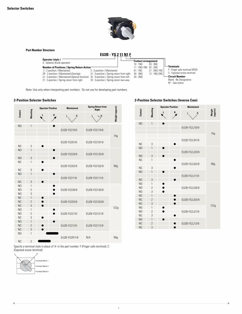
Selector Switches
Operator (style )S : Selector (Knob operator)
Number of Positions / Spring Return Action 2 : 2-position / Maintained2R : 2-position / Maintained (Overlap)2J : 2-position / Maintained (Special function)21 : 2-position / Spring return from right
3 : 3-position / Maintained31 : 3-position / Spring return from right32 : 3-position / Spring return from left33 : 3-position / Spring return two-way
Terminals F : Finger safe terminal (IP20) C : Exposed screw terminalCircuit Number Blank : No DesignationN* : See charts
Contact arrangement10 : 1NO11 : 1NO-1NC01 : 1NC30 : 3NO20 : 2NO
03 : 3NC02 : 2NC21 : 2NO-1NC12 : 1NO-2NC
Part Number StructureEU2B - YS 2 11 N1 F
Note: Use only when interpreting part numbers. Do not use for developing part numbers.
2-Position Selector Switches
Cont
act
Mou
ntin
g Operator Position Maintained Spring Return from Right
Wei
ght (
appr
ox)
L R L R L R
NO 1 ●
EU2B-YS210➃ EU2B-YS2110➃
74g
EU2B-YS201➃ EU2B-YS2101➃
NC 3 ●
NO 1 ●
EU2B-YS220➃ EU2B-YS2120➃
98g
NO 3 ●
NC 1 ●
EU2B-YS202➃ EU2B-YS2102➃
NC 3 ●
NO 1 ●
EU2B-YS211➃ EU2B-YS2111➃
NC 3 ●
NO 1 ●
EU2B-YS230➃ EU2B-YS2130➃
122g
NO 2 ●
NO 3 ●
NC 1 ●
EU2B-YS203➃ EU2B-YS2103➃NC 2 ●
NC 3 ●
NO 1 ●
EU2B-YS221➃ EU2B-YS2121➃NO 2 ●
NC 3 ●
NO 1 ●
EU2B-YS212➃ EU2B-YS2112➃NC 2 ●
NC 3 ●
NO 1EU2B-YS2R11➃ N/A 98g
NC 2
Specify a terminal style in place of ➃ in the part number: F (Finger safe terminal), C (Exposed screw terminal)
RL
�Contact Block 1
�Contact Block 2
�Contact Block 3
2-Position Selector Switches (Inverse Cam)
Cont
act
Mou
ntin
g Operator Position Maintained
Wei
ght
(app
rox)
L R L R
NO 1 ●
EU2B-YS2J10➃
74g
EU2B-YS2J01➃
NC 3 ●
NO 1 ●
EU2B-YS2J20➃
98g
NO 3 ●
NC 1 ●
EU2B-YS2J02➃
NC 3 ●
NO 1 ●
EU2B-YS2J11➃
NC 3 ●
NO 1 ●
EU2B-YS2J30➃
122g
NO 2 ●
NO 3 ●
NC 1 ●
EU2B-YS2J03➃NC 2 ●
NC 3 ●
NO 1 ●
EU2B-YS2J21➃NO 2 ●
NC 3 ●
NO 1 ●
EU2B-YS2J12➃NC 2 ●
NC 3 ●

5
3-Position Selector Switches
Cont
act
Mou
ntin
g
Operator Position Maintained Spring Return from Right Spring Return from Left Spring Return Two Way
Wei
ght
(app
rox)
L C R L C R L C R L C R L C R
NO 1 ●
EU2B-YS320➃ EU2B-YS3120➃ EU2B-YS3220➃ EU2B-YS3320➃
98g
NO 3 ●
EU2B-YS320N1➃ EU2B-YS3120N1➃ EU2B-YS3220N1➃ EU2B-YS3320N1➃NO 2 ● ●
NO 3 ●
NC 1
EU2B-YS302➃ EU2B-YS302➃ EU2B-YS3202➃ EU2B-YS3302➃
NC 3
EU2B-YS302N1➃ EU2B-YS3102N1➃➂ EU2B-YS3202N1➃➂ EU2B-YS3302N1➃NC 2 ●
NC 3
NO 1 ●
EU2B-YS311➃ EU2B-YS311➃ EU2B-YS3211➃ EU2B-YS3311➃
NC 3
NC 1
EU2B-YS311N1➃ EU2B-YS3111N1➃ EU2B-YS3211N1➃ EU2B-YS3311N1➃
NO 3 ●
NO 1 ●
EU2B-YS311N2➃ EU2B-YS3111N2➃ EU2B-YS3211N2➃ EU2B-YS3311N2➃NC 2 ●
EU2B-YS311N3➃ EU2B-YS3111N3➀ EU2B-YS3211N3➀ EU2B-YS3311N3➀NC 2 ●
NO 3 ●
EU2B-YS311N4➃ EU2B-YS3111N4➃ EU2B-YS3211N4➃ EU2B-YS3311N4➃NO 2 ● ●
NC 3
NO 1 ●
EU2B-YS330➃ EU2B-YS3130➃ EU2B-YS3230➃ EU2B-YS3330➃
122g
NO 2 ● ●
NO 3 ●
NC 1
EU2B-YS303➃ EU2B-YS3103➃ EU2B-YS3203➃ EU2B-YS3303➃NC 2 ●
NC 3
NO 1 ●
EU2B-YS3 21N1➃ EU2B-YS3121N1➃ EU2B-YS3221N1➃ EU2B-YS3321N1➃NC 2 ●
NO 3 ●
NC 1
EU2B-YS3 12N1➃ EU2B-YS3112N1➃ EU2B-YS3212N1➃ EU2B-YS3312N1➃NO 2 ● ●
NC 3
Specify a terminal style in place of ➃ in the part number: F (Finger safe terminal), C (Exposed screw terminal)
Contact Block 1
Contact Block 2
Contact Block 3
C
RL

6
Key Selector Switches
Operator (style )SK:Key selector (Key operator)
Number of Positions / Spring Return Action 2 : 2-position / Maintained2R : 2-position / Maintained (Overlap)2J : 2-position / Maintained (Special function)21 : 2-position / Spring return from right
3: 3 -position / Maintained31 : 3-position / Spring return from right32 : 3-position / Spring return from left33 : 3-position / Spring return two-way
Terminals F : Finger safe terminal (IP20) C : Exposed screw terminalCircuit Number Blank : No DesignationN* : See the following charts
Contact arrangement10 : 1NO11 : 1NO-1NC01 : 1NC30 : 3NO20 : 2NO
03 : 3NC02 : 2NC21 : 2NO-1NC12 : 1NO-2NC
Part Number StructureEU2B - YSK 2 11 N1 F A
Key Removable PositionSee Key removable option codes below
Note: Use only when interpreting part numbers. Do not use for developing part numbers.
2-Position Key Selector Switches
Cont
act
Mou
ntin
g
Operator Position Maintained Spring Return from Right
Wei
ght (
appr
ox)
L R L R L R
NO 1 ●
EU2B-YSK210➃➂ EU2B-YSK2110➃➂
96g
EU2B-YSK201➃➂ EU2B-YSK2101➃➂
NC 3 ●
NO 1 ●
EU2B-YSK220➃➂ EU2B-YSK2120➃➂
120g
NO 3 ●
NC 1 ●
EU2B-YSK202➃➂ EU2B-YSK2102➃➂
NC 3 ●
NO 1 ●
EU2B-YSK211➃➂ EU2B-YSK2111➃➂
NC 3 ●
NO 1 ●
EU2B-YSK230➃➂ EU2B-YSK2130➃➂
144g
NO 2 ●
NO 3 ●
NC 1 ●
EU2B-YSK203➃➂ EU2B-YSK2103➃➂NC 2 ●
NC 3 ●
NO 1 ●
EU2B-YSK221➃➂ EU2B-YSK2121➃➂NO 2 ●
NC 3 ●
NO 1 ●
EU2B-YSK212➃➂ EU2B-YSK2112➃➂NC 2 ●
NC 3 ●
NO 1EU2B-YSK2R11➃➂ N/A 120g
NC 2
Key is removable in all maintained positions. Specify key removal position in place of ➂ in the part number. See table.Specify a terminal style in place of ➃ in the part number: F (Finger safe terminal), C (Exposed screw terminal).
Contact Block 1
Contact Block 2
Contact Block 3
Operator Position
Contact Block PositionRL
The key can be released in any maintained position.
2-Position Key Selector Switches (Inverse Cam)
Cont
act
Mou
ntin
g
Operator Position Maintained
Wei
ght (
appr
ox)
L R L R
NO 1 ●
EU2B-YSK2J10➃➂
96g
EU2B-YSK2J01➃➂
NC 3 ●
NO 1 ●
EU2B-YSK2J20➃➂
120g
NO 3 ●
NC 1 ●
EU2B-YSK2J02➃➂
NC 3 ●
NO 1 ●
EU2B-YSK2J11➃➂
NC 3 ●
NO 1 ●
EU2B-YSK2J30➃➂
144g
NO 2 ●
NO 3 ●
NC 1 ●
EU2B-YSK2J03➃➂NC 2 ●
NC 3 ●
NO 1 ●
EU2B-YSK2J21➃➂NO 2 ●
NC 3 ●
NO 1 ●
EU2B-YSK2J12➃➂NC 2 ●
NC 3 ●
➂ Key Removable Option Codes (2-position)
Code Description
A Key removable in any position
B Key removable in left position
C Key removable in right position
7
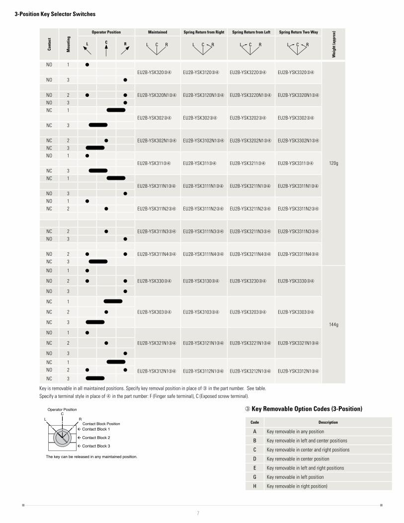
3-Position Key Selector Switches
Cont
act
Mou
ntin
g
Operator Position Maintained Spring Return from Right Spring Return from Left Spring Return Two Way
Wei
ght (
appr
ox)
L C R L C R L C R L C R L C R
NO 1 ●
EU2B-YSK320➂➃ EU2B-YSK3120➂➃ EU2B-YSK3220➂➃ EU2B-YSK3320➂➃
120g
NO 3 ●
EU2B-YSK320N1➂➃ EU2B-YSK3120N1➂➃ EU2B-YSK3220N1➂➃ EU2B-YSK3320N1➂➃NO 2 ● ●
NO 3 ●
NC 1
EU2B-YSK302➂➃ EU2B-YSK302➂➃ EU2B-YSK3202➂➃ EU2B-YSK3302➂➃
NC 3
EU2B-YSK302N1➂➃ EU2B-YSK3102N1➂➃ EU2B-YSK3202N1➂➃ EU2B-YSK3302N1➂➃NC 2 ●
NC 3
NO 1 ●
EU2B-YSK311➂➃ EU2B-YSK311➂➃ EU2B-YSK3211➂➃ EU2B-YSK3311➂➃
NC 3
NC 1
EU2B-YSK311N1➂➃ EU2B-YSK3111N1➂➃ EU2B-YSK3211N1➂➃ EU2B-YSK3311N1➂➃
NO 3 ●
NO 1 ●
EU2B-YSK311N2➂➃ EU2B-YSK3111N2➂➃ EU2B-YSK3211N2➂➃ EU2B-YSK3311N2➂➃NC 2 ●
EU2B-YSK311N3➂➃ EU2B-YSK3111N3➂➃ EU2B-YSK3211N3➂➃ EU2B-YSK3311N3➂➃NC 2 ●
NO 3 ●
EU2B-YSK311N4➂➃ EU2B-YSK3111N4➂➃ EU2B-YSK3211N4➂➃ EU2B-YSK3311N4➂➃NO 2 ● ●
NC 3
NO 1 ●
EU2B-YSK330➂➃ EU2B-YSK3130➂➃ EU2B-YSK3230➂➃ EU2B-YSK3330➂➃
144g
NO 2 ● ●
NO 3 ●
NC 1
EU2B-YSK303➂➃ EU2B-YSK3103➂➃ EU2B-YSK3203➂➃ EU2B-YSK3303➂➃NC 2 ●
NC 3
NO 1 ●
EU2B-YSK321N1➂➃ EU2B-YSK3121N1➂➃ EU2B-YSK3221N1➂➃ EU2B-YSK3321N1➂➃NC 2 ●
NO 3 ●
NC 1
EU2B-YSK312N1➂➃ EU2B-YSK3112N1➂➃ EU2B-YSK3212N1➂➃ EU2B-YSK3312N1➂➃NO 2 ● ●
NC 3
Key is removable in all maintained positions. Specify key removal position in place of ➂ in the part number. See table.Specify a terminal style in place of ➃ in the part number: F (Finger safe terminal), C (Exposed screw terminal).
Contact Block 1
Contact Block 2
Contact Block 3
Operator Position
Contact Block Position
CRL
The key can be released in any maintained position.
➂ Key Removable Option Codes (3-Position)
Code Description
A Key removable in any position
B Key removable in left and center positions
C Key removable in center and right positions
D Key removable in center position
E Key removable in left and right positions
G Key removable in left position
H Key removable in right position)

8
Meters
Part Number Structure - AC AmmeterEU2B - YM 5 3 A 10 F R
Function M : MeterInput current 1 : 1A 5 : 5ASpecification of overload scale3: 3 times 2 : 2 times 5 : 5 times N:NonType of meter A : AC ammeter Measuring rangeDirect measuring 1 : 1A 5 : 5A For current transformers: 10 : 10A 15 : 15A 20 : 20A 30:30A 50:50A 60 : 60A 75 : 75A 100:100A 150:150A etc.
Set pointerblank : non -R : with set pointer
Terminals F : Finger safe terminal (IP20) C : Exposed screw terminal
Part Number Structure - DC Ammeter or VoltmeterEU2B - YM 010 VD F-PER-R
Function M : MeterInput voltage or current 010 : 0-10V001 : 0-1mA420 : 4-20mA etc.
Specification of scale-PER : 0~100%-60HZ : 0~60Hz-80HZ : 0~80Hz etc.
Set pointerblank : non -R : with set pointer
Terminals F : Finger safe terminal (IP20) C : Exposed screw terminal
Type of meter VD : DC voltmeterMD : DC ammeter
Note: Use only when interpreting part numbers. Do not use for developing part numbers.
Input Part Number Description Weight (approx.)
AC input meter (ammeter)
EU2B-YM53A5➃ Capacity: 5A Expansion scale: x3
270g
EU2B-YM53A10➃ Capacity:10/5A Expansion scale: x3
EU2B-YM13A10➃ Capacity:10/1A Expansion scale: x3
EU2B-YM53A15➃ Capacity:15/5A Expansion scale: x3
EU2B-YM13A15➃ Capacity:15/1A Expansion scale: x3
EU2B-YM13A20➃ Capacity:20/1A Expansion scale: x3
EU2B-YM53A30➃ Capacity:30/5A Expansion scale: x3
EU2B-YM13A30➃ Capacity:30/1A Expansion scale: x3
EU2B-YM53A50➃ Capacity:50/5A Expansion scale: x3
EU2B-YM53A60➃ Capacity:60/5A Expansion scale: x3
EU2B-YM53A75➃ Capacity:75/5A Expansion scale: x3
EU2B-YM53A100➃ Capacity:100/5A Expansion scale: x3
EU2B-YM53A150➃ Capacity:150/5A Expansion scale: x3
DC input meter
EU2B-YM010VD➃-PER 0-10V DC Input Scale: 0 to 100%
EU2B-YM010VD➃-60HZ 0-10V DC Input Scale: 0 to 60Hz
EU2B-YM001MD➃-PER 0-1mA DC Input Scale: 0 to 100%
EU2B-YM001MD➃-60HZ 0-1mA DC Input Scale: 0 to 60Hz
EU2B-YM001MD➃-80HZ 0-1mA DC Input Scale: 0 to 80Hz
EU2B-YM420MD➃-PER 4-20mA DC Input Scale: 0 to 100%
EU2B-YM420MD➃-60HZ 4-20mA DC Input Scale: 0 to 60Hz
Specify a terminal style in place of ➃ in the part number: F (Finger safe terminal), C (Exposed screw terminal)

9
DIMENSIONSAll dimensions in mm
PushbuttonsShown with finger-safe contacts
Emergency Stop SwitchesShown with finger-safe contacts
Selector SwitchesShown with finger-safe contacts
Key Selector SwitchShown with finger-safe contacts
Pilot LightsShown with finger-safe contacts
32.5
61.4
MetersShown with finger-safe contacts
Mounting Hole DimensionsPanel thickness: 1.0 to 4.5 mm. *Note: The meter can be mounted on the top mounting holes of a standard 50mm mounting centers. The meter can be mounted on any mounting hole with a 70mm or larger mounting center.
32.2 67.713.3
48.0
ø 40
.0
33.0
Flush
13.3 67.7
ø40
1.0 to 4.5 (panel thickness)
39Mushroom
24.5
ø40
Extended
ø 24
.0
19.3
47.4
32.2
38.4
ø 40
.0
1.0 to 4.5 (panel thickness)
35.0 67.7
32.2
47.427.3
ø 40
.0
67.7
1.0 to 4.5(panel thickness)
38.4
32.2
47.4 37.3 67.7
1.0 to 4.5 (panel thickness)
ø 40
.0
38.4
32.0
1.0 to 4.5 (panel thickness)
67.7
ø 40
.0
20.3
ø 40
.0
67.720.3
62.0
ø 28
.0
(Panel thickness)1.0 to 4.5
8.0
33.5 62.1
ø 64
.0
33+0
.5 0
4.8+0.2 0ø30.5 +0.5 0
50 m
inim
um (*
note
)
70 minimum

10
ACCESSORIES
NameplatesUsed for pilot light, pushbutton, selector switch, and key selector switch.
Appearance Part Number Dimensions
EU9Z-NM
4.5
Marking Plate40
ø40
28.5
(35)
1.5(6.5)
Nameplate Inserts
Appearance Legend Part Number
Blank EU9Z-NP0ON EU9Z-NP1
OFF EU9Z-NP2
START EU9Z-NP3
STOP EU9Z-NP4
OFF-ON EU9Z-NP31
HAND-AUTO EU9Z-NP35
HAND-OFF-AUTO EU9Z-NP53
Material: AluminumInstalling the Insert to the Nameplate Removing the Insert from the Nameplate
Insert
➀
➁
Flat screwdriver
Insert
Nameplate
To remove the Insert, insert a flat screwdriver between the Insert and Nameplate.
Rubber Boots
Appearance Description/Usage Part Number
For Flush Pushbuttons
Not for use with name plate EU9Z-DB1
For Flush Pushbuttons
For use with name plate EU9Z-DB1N
For Extended Pushbuttons
Not for use with name plate EU9Z-DB2
For Extended Pushbuttons
For use with name plate EU9Z-DB2N
Note: Rubber boot must be mounted on flush or extended pushbuttons to achieve UL Type 4X rating
Emergency Stop Switch Nameplate Stickers
Appearance Legend Part Number Dimensions
Blank EU9Z-NVS0
E M E R G E N C Y
S T O P
ø58
ø40.5
ø58
ø40.5
EU9Z-NVS0 EU9Z-NVS27
Emergency Stop EU9Z-NVS27
E M E R G E N C Y
S T O P
ø58
ø40.5
ø58
ø40.5
EU9Z-NVS0 EU9Z-NVS27
Material: synthetic paper Background: yellow Legend: black
Padlock CoverEU2B-YB2 extended pushbutton: to maintain latched status EU2B-YB1 flush pushbutton/EU2B-YSK key selector switch: to prevent operation
Appearance Part Number Dimensions
EU9Z-PC
44 8
32.1
46
24.5
Material: Stainless Steel
Emergency Stop Switch Padlock CoverUsed with EU2B-YBV emergency stop switch to maintain the switch in the latched status.
Appearance Part Number Dimensions
EU9Z-PCE
55.4
50
4632.2
8
Base
Coating: yellow Material: Stainless Steel
Mounting Hole PlugUsed to plug unused mounting holes (ø30.5) on the mounting panel.
Appearance Part Number Dimensions / Usage
EU9Z-BP ø40
1.0 to 10.5(panel thickness)
13.3
23.2

11
Buttons
Appearance Style Part Number Button Color Code
Flush HW1A-B1➀
Specify a color code in place of ➀ in the Ordering Number.R : redG : greenB : blackY : yellowW : whiteS : blue
Extended HW1A-B2➀
ø40 Mushroom HW1A-B4➀
Material: Polyacetal
Lenses
Appearance Lens Color Part Number
Red EU9Z-LR
Green EU9Z-LG
Amber EU9Z-LA
Yellow EU9Z-LY
White EU9Z-LW
Blue EU9Z-LS
Material: AS resin (gasket supplied)
LED Lamps
Operating Voltage
Current Draw Part Number Illumination Color Code Base
AC DC
6V AC/DC±10% 8mA
7mA(A, R, W)5.5mA(G, PW, S)
LSTD-6➀
Specify a color code in place of ➀ in the part numberR : redG : greenA : amberPW : whiteS : blueUse a white (PW) LED with yellow (Y) lens.
BA9S/1312V AC/DC±10% 11mA 10mA LSTD-1➀
24V AC/DC±10% 11mA 10mA LSTD-2➀
Wiring
Applicable Wires Stranded wire: 1.5 to 2.5 mm², solid wire: ø1.2 to ø1.6 mm (AWG16 to 14)Note: Do not connect more than 2 wires to the same terminal.
Applicable crimping terminalRing and spade terminals cannot be used with IP20 finger-safe terminal blocks.When connecting 2 ferrules to the EU2B control unit, use ferrules without insulating sheath.
3.4maximum
5.5minimum
5.5 minimum
φ 3.6
minimum
Without insulating sheath
Insulatingsheath
Wire
8.0maximum
(*1)
1.8
max
imum
Insulating sheath
8.0maximum
(*1)
1.8
max
imum
3.6
min
imum
6.9
max
imum
6.9
max
imum
Recommended crimping terminal (WAGO)Ferrule with insulating sheath: 216-204Ferrule without insulating sheath: 216-104Crimping plier: 206-204
Recommended Tightening Torque EU2B control units (M3.5): 1.0 to 1.3 N·m
WarningIncorrect wiring may cause fire hazard. Observe the following conditions.• Be sure to install an insulating sheath on the crimping terminal or the crimping terminal
with insulation.• When connecting solid wires or stranded wires directly, strip the insulation, mentioned
below, and insert the wire all the way in. EU2B Control units: 8.6 mm maximum Crimping terminal: 8 to 9 mm
• When using stranded wires, make sure that there are no wire whiskers.• Make sure that the spade crimping terminals and ferrules are inserted all the way in.
Insulating tube (covered)
Wire5.5 to 6.0

12
OPERATING INSTRUCTIONS
Removing and Installing the Contact Unit / Lamp UnitTo remove the contact unit or the lamp unit from the operator, pull the protruding yellow part of the locking lever outwards as shown in the figure below using a screwdriver, and turn it to the left. The contact unit or lamp unit can be removed.
When the contact unit is removed from the emergency stop switch operator, the NO contact closes and the NC contact opens. Do not turn the locking lever when the contact unit is removed from the operator (the red indica-tor is protruding out. See the figure below) or the switch can be damaged.
Panel mounting for the operator, lens unit and meterRemove the locking ring from the operator and check that the rubber gasket is in place. Insert the operator from the panel front into the panel hole. Place the projection on the operator with TOP marking upward and the recess on the mounting panel in the same direction. (The meter has no projection.)Tighten the locking ring using ring wrench XN9Z-T1 to a torque of 2.5 Nm. When using a name-plate or padlocking cover, install it between the operator and panel. Make sure that the groove of the namplate or padlocking cover and the projection on the TOP marking of the operator are in the same direction. Note: The locking ring for emergency stop switches and meter is metallic. The meter can’t mount the nameplate or podlocking cover.
Installing the contact unit and lamp unitTo install the contact unit, place theTOP marking on the operator and the TOP marking on the con-tact block adapter in the same direction, and then attach the contact unit to the operator. Then turn the locking lever to the right. Follow the same procedure when installing the lamp unit.When installing the lamp unit, check that the inner lens is not loose.The contact block adapters for emergency stop switches cannot be used for the pushbutton, selector and key selector switches.
TOP marking Projection Nameplate orPadlocking cover
Recess on the panel
Locking ring
Nameplate gasket
Recess on the Nameplate
Rubber gasket
Removing the Contact BlockTo remove the contact block, insert a flat screwdriver under the latch of the contact block adaptor and disengage the latch as shown in the figure below.
Installing the Contact blockWhen installing the contact block after maintenance or wiring, make sure that the contact configuration is correct. Installing the contact block in the incorrect position or incomplete instal-lation may cause malfunction of the switch.Remove the contact block from the operator before installing the contact block to the contact block adaptor. Also make sure that the contact block is correctly installed to the contact block adaptor before attaching the operator. Do not install the contact block adaptor with the operator attached. Otherwise, malfunction may result.
Accessories
Padlock CoverThe following padlocks and hasps can be used.
(Padlock Size) a b cFlush/extended pushbutton/key selector switch
ø3.5 to 7.0 mm 15 mm min. 70 mm max.
Emergency Stop Switch ø5.5 to 7.0 mm — —
Recommended HaspManufacturer Part No.
Panduit PSL-1, PSL-1A, PSL-1.5, PSL-1.5A, PSL-HD1
Master Lock 420, 421
Padlock and hasp are available in various shapes and sizes. Make sure that they do not interfere with the control units. Note: Not supplied by IDEC.Keep the total weight of padlock and hasp under 1500g max, otherwise the switch may malfunc-tion or result in failure. No vibration should be applied when padlock or hasp are installed. When padlock or hasp are disfigured, stop usage immediately. Ensure that no shock or electric sparks are generated.When using the plate lock padlock cover with the extended pushbutton, the switch contact may turn on/off when the cover is being installed. Ensure to provide functional safety measure to prevent unexpected startup.When using the padlock cover on the safety-related part of the control system, observe safety standards and regulations of the relevant country or region. Also be sure to perform risk assess-ment before operation.
Installing EU9Z-PC Padlock Cover(Flush/extended pushbtton/key selector switch)EU9Z-PC can be installed in the following two ways.Remove the cover in the reverse step of installing the cover. Do not install or remove the cover forcefully, or it will cause failure.[Installation A]
[Installation B]This method is effective when the neighboring control unit interferes when installing in method A.
➀(Lift)
➁(Turn)
locking lever➂
(Pull)
➀(Lift)
➁(Turn)
locking lever➂
(Pull)
EU2B-YB/ YBVEU2B-YS/ YSK
EU2B-YL
TOP
indicator (red)
locking lever
TOP marking
EU2B-YBEU2B-YS
TOP marking
inner lens
EU2B-YL
TOP
➀➀
➁ ➁
Flat Screwdriver
Cover� �
��
�Cover

Installing EU9Z-DB Rubber BootsTo install the rubber boot on flush and extended pushbuttons, place the rubber boot on the cap and push the rubber boot holder straight. The notches around the rubber boot must show evenly.
Rubber boot holder
Rubber boot
Cap
Notches
Notches forscrewdriver
Push-in position
Push the rubber boot holder further around on the two notches on the holder so that the holder fits the button completelyMake sure that the rubber boot and rubber boot holder are installed straight.
Align
On Nameplate Types, the EU2B and the rubber boot holder must be aligned so that when installed, the anti-rotation projection on the EU2B comes to the center of the groove on the holder. Make sure that the rubber boot is installed completely, otherwise Type 4X degree of protection cannot be obtained. Water droplets might enter the rubber boot, but no water will enter the control box.
To remove the rubber boot from the flush and extended pushbuttons, gently insert the slotted screwdriver (0.5t x 4w or below) inside a notch on the rubber boot holder and tilt to the direction shown by the arrow ➀. To prevent damage, do not apply excessive force to the EU2B when removing the rubber boot.
Maintenance and InspectionEU2B switches should be installed in an appropriate control box.
Maintenance and Inspection MethodPerform daily or periodical maintenance and inspection for items such as damage and tempera-ture rise of the EU2B switches listed in the Maintenance and Inspection table below.
Maintenance and Inspection
Inspection Items Inspection Method Inspections Measures
Enclosure base Visual No rustingNo damages
CleaningRust-resistant treat-ment
Tightening bolt, screws Visual, tactile No loosening
No rustingTighteningCleaning
Packings VisualNo cracksNo apparent deforma-tion
Replacement
Connecting parts Visual, tactileNo loosening of screwsNo dirt on insulation materials
TighteningCleaning
Temperature rise Thermometer, tactile Surface temperature 80ºC max. Investigate the cause
DisposalObserve laws and regulations set by each country concerning refuse disposal.
Safety PrecautionsUse EU2B switches that are applicable for use in hazardous areas (potentially explosive atmo-sphere where explosive gas or vapor may exist), otherwise explosion or fire hazard may result.• EU2B switches can be installed only in zones 1 and 2. Do not use in zone 0.• Turn power off to the EU2B switches before installation, removal, wiring, or maintenance,
otherwise explosion, fire hazard, or electric shock may result.• Do not disassemble, repair, or modify, otherwise damage or accident may result. • Do not use damaged EU2B switches, otherwise damage or accident may result.• When connecting external devices, make sure that each cable is connected to the correct
terminal, otherwise electric shock, fire hazard, or explosion may result.• Use wires of a proper size to meet voltage and current requirements. Incorrect wiring may
cause abnormal temperature rise and lead to fire hazard and explosion.• Connect the grounding terminal to a proper ground, otherwise electric shock, fire hazard,
or explosion may result.• Operate the EU2B switches at the rated current and voltage specified in this catalog,
otherwise short-circuiting, fire hazard, or explosion may result.• Stop operation immediately if abnormal operation occurs. Otherwise, a secondary ac-
cident may occur.
IDEC Corporation • 1175 Elko Drive • Sunnyvale, CA 94089 • 800-262-IDEC (4332) • Fax: 408-745-5258 • www.IDEC.com/usa©2015 IDEC Corporation. All Rights Reserved. EU9Y-DS100-0 pdf only