Cat Tmax PV 2015 video - Valin Thermal Solutions & … | 1SDC210054D0203 | ABB catalogue Thanks to...
48
Technical catalog - Edition 2015 SACE Tmax PV Adaptability, versatility and complete freedom continue
Transcript of Cat Tmax PV 2015 video - Valin Thermal Solutions & … | 1SDC210054D0203 | ABB catalogue Thanks to...

Technical catalog - Edition 2015
SACE Tmax PVAdaptability, versatility and complete freedom continue

2 | 1SDC210054D0203 | ABB catalogue
SACE Tmax PV automatic molded case circuit-breakers
and molded case switch-disconnectors
Using the Tmax PV line, the customer is able to select the
most appropriate device for any Solar PV need.
Under IEC 60947-3, Tmax PV offers switch-disconnectors to
meet standard 1100V DC applications. In addition, it offers
the versatility of extended capacities to 1500V DC for the
increasingly demanding solar applications of today’s market.
Finally, connection jumpers are an available option for the
IEC switch-disconnectors to increase safety and ease of
installation.
Tmax Automatic Circuit-breakers according to IEC up to
1000V DC are available as a special version of the standard
Tmax line. Information about that range can be found in the
Tmax technical catalogue.
Common data
Operating temperature [°C] -25 °C … +70 °C
Storage temperature [°C] -40 °C … +70 °C
Numbers of poles 4
Version fixed
The Tmax PV line of IEC switch-disconnectors and UL switch-disconnectors and
molded case circuit-breakers expands upon Tmax T Generation’s history of offering
complete adaptability, versatility and freedom for any type of application.
Altitude derating
Altitude [mt] In [%] Ue [%]
2000 100 100
3000 98 88
4000 95 78
5000 85 68

ABB catalogue | 1SDC210054D0203 | 3
Under UL 489B, Tmax PV offers adaptability in the form of
the availability of both switch-disconnectors and molded case
circuit-breakers. Multiple formats allows for the ability of a
uniform end product and shared accessories. In addition,
ABB offers connection jumpers as a mandatory accessory
to Tmax PV UL. The jumpers provide simple, safe use and
ensured compliance to new UL regulations.
Common data
Operating temperature [°C] -25 °C … +70 °C
Storage temperature [°C] -40 °C … +70 °C
Numbers of poles 3 - 4
Version fixed
Altitude derating
Altitude [mt] In [%] Ue [%]
2000 100 100
3000 98 88
4000 95 78
5000 85 68

4 | 1SDC210054D0203 | ABB catalogue
Thanks to the extremely low short-circuit current generated by
PV panels, the use of molded-case switch-disconnectors is
widely adopted both in combiner boxes and in the DC side of
the inverters:
Molded case switch-disconnectors up to 1100V DC in compliance with IEC 60947-3Electrical charachteristics
Tmax PV switch-disconnectors in compliance with the IEC60947-3 T1D/PV T3D/PV T4D/PV T5D/PV T6D/PV T7D/PV 1)
Rated service current in category DC22 B, Ie (A) 160 200 250 500 800 1250-1600
Number of poles (No.) 4 4 4 4 4 4
Rated service voltage, Ue 1100V DC 1100V DC 1100V DC 1100V DC 1100V DC 1100V DC
Rated impulse withstand voltage, Uimp (kV) 8 8 8 8 8 8
Rated insulation voltage, Ui (V) 1150V DC 1150V DC 1150V DC 1150V DC 1150V DC 1150V DC
Test voltage at industrial frequency for 1 minute (V) 3500 3500 3500 3500 3500 3500
Rated short-circuit making capacity,
switch-disconnector only, Icm(kA) 1.92 2.4 3 6 9.6 19.2
Rated short-time withstand current for 1s, Icw (kA) 1.92 2.4 3 6 9.6 19.2
Versions F F F F F F
Standard terminals FC Cu FC Cu F F F F
Mechanical life (No. Operations) 15000 15000 7500 7500 7500 20000
Electrical life (operations @ 1100V DC) (No. Operations) 500 500 500* 500* 500* 500*
Basic dimensions W (mm/in) 102/4.02 140/5.52 140/5.52 186/7.33 280/11.02 280/11.02
D (mm/in) 70/2.76 70/2.76 103.5/4.07 103.5/4.07 103.5/4.07154/6.06 (manual)
178/7.01 (motorized)
H (mm/in) 130/5.12 150/5.91 205/8.07 205/8.07 268/10.55 268/10.55
Weight (with standard terminals only) (kg/lbs) 1.2/2.65 2/4.41 3.05/6.72 4.15/9.15 12/26.4612.5/27.56 (manual)
14/30.86 (motorized)
1) installation in vertical position only
* openings with SOR or UVR
Molded case switch-disconnectors up to 1500V DC in compliance with IEC 60947-3Electrical charachteristics
Tmax PV switch-disconnectors in compliance with the IEC60947-3 T4D/PV-E T5D/PV-E T7D/PV-E 1)
Rated service current in category DC22 A, Ie (A) 250 500 1250-1600
Number of poles (No.) 4 4 4
Rated service voltage, Ue 1500V DC 1500V DC 1500V DC
Rated impulse withstand voltage, Uimp (kV) 8 8 8
Rated insulation voltage, Ui (V) 1500V DC 1500V DC 1500V DC
Test voltage at industrial frequency for 1 minute (V) 3500 3500 3500
Rated short-circuit making capacity,
switch-disconnector only, Icm(kA) 3 6 19.2
Rated short-time withstand current for 1s, Icw (kA) 3 6 19.2
Versions F F F
Standard terminals F F F
Mechanical life (No. Operations) 7500 7500 20000
Electrical life (operations @ 1500V DC) (No. Operations) 1000* 1000* 500*
Basic dimensions W (mm/in) 140/5.52 186/7.33 280/11.02
D (mm/in) 103.5/4.07 103.5/4.07 178/7.01
H (mm/in) 205/8,07 205/8.07 268/10.55
Weight (with standard terminals only) (kg/lbs) 3.05/6.72 3,15/9.15 14/30.86
1) installation in vertical position only
* openings with SOR or UVR
SACE Tmax PV automatic molded case circuit-breakers
and molded case switch-disconnectors

ABB catalogue | 1SDC210054D0203 | 5
Molded case switch-disconnectors up to 1000V DC in compliance with UL 489BElectrical charachteristics
Tmax PV UL switch-disconnectors T1N-D/PV T4N-D/PV T5N-D/PV T6N-D/PV T7N-D/PV 1)
Frame size (A) 100 200 400 600-800 1000
Rated service current (A) 100 200 400 600-800 1000
Number of poles (No.) 4 3 3 4 4
Rated service voltage (V) 1000V DC 1000V DC 1000V DC 1000V DC 1000V DC
Short-circuit current withstand (kA) 1.2 3 5 10 18
Magnetic override (kA) - 3 5 10 -
Versions F F F F F
Connections* Jumpers Jumpers Jumpers Jumpers Jumpers
Terminals provided with Jumper kit FCCu FCCuAl FCCu-ES FCCuAl-EF FCCuAl-F
Mechanical life (No. Operations) 15000 7500 7500 7500 20000
Electrical life (operations @ 1000V DC) (No. Operations) 1000 1000** 500** 500** 500**
Basic dimensions W (mm/in) 102/4.02 105/4.13 140/5.52 280/11.02 280/11.02
D (mm/in) 70/2.76 103.5/4.07 103.5/4.07 103.5/4.07 178/7.01
H (mm/in) 130/5.12 205/8.07 205/8.07 268/10.55 268/10.55
Weight (with standard terminals only) (kg/lbs) 1.2/2.65 2.35/5.18 3.25/7.17 12/26.46 14/30.86
1) installation in vertical position only
* Selection of one of the jumper connection options is mandatory for Tmax PV UL
** openings with SOR or UVR
Whenever a consistent short-circuit current can be found (like
in recombiner boxes), 1000V DC automatic circuit-breakers
are available in the Tmax range. Below is the UL489B
automatic circuit-breaker offering:
Molded case circuit-breakers up to 1000V DC in compliance with UL 489BElectrical charachteristics
Tmax PV UL MCCBs T4N/PV T5N/PV T6N/PV
Frame size (A) 200 400 600-800
Rated service current (A) 40-200 225-400 600-800
Number of poles (No.) 3 3 4
Rated service voltage (V) 1000V DC 1000V DC 1000V DC
Short-circuit interrupting rating @ 1000V DC (kA) 7.5 5 10
Trip Unit TMD/TMA TMF/TMA TMA
Versions F F F
Standard terminals F F F
Connections* Jumpers Jumpers Jumpers
Terminals provided with Jumper kit FCCuAl FCCuAl-FCCu-ES FCCuAl-EF
Mechanical life (No. Operations) 7500 7500 7500
Electrical life (operations @ 1000 VDC) (No. Operations) 1000** 500** 500**
Basic dimensions W (mm/in) 105/4.13 140/5.52 280/11.02
D (mm/in) 103.5/4.07 103.5/4.07 103.5/4.07
H (mm/in) 205/8.07 205/8.07 268/10.55
Weight (with standard terminals only) (kg/lbs) 2.35/5.18 3.25/7.17 12/26.46
* Selection of one of the jumper connection options is mandatory for Tmax PV UL
** openings with SOR or UVR

6 | 1SDC210054D0203 | ABB catalogue
The circuit-breakers are fitted with thermal magnetic trip units
and are used for protection of direct current in solar networks.
They allow the protection against overload with a thermal
device that uses the bimetal technique, and protection against
short-circuit with a magnetic device.
The range of T4, T5 and T6 circuit-breakers for photovoltaic
applications includes the following:
- T4 (up to 50A) circuit-breakers equipped with TMD thermal magnetic trip units with adjustable thermal
threshold (I1 = 0.7…1 x In) and fixed magnetic threshold
(I3 = 10 x In).
- T4, T5 and T6 circuit-breakers equipped TMA thermal magnetic trip units with adjustable thermal threshold
(I1 = 0.7…1 x In) and adjustable magnetic threshold
The UL circuit-breaker range is divided into three different frames, T4, T5 and
T6, with an application range from 40A to 800A and breaking capacities up to
10kA at 1000V DC.
SACE Tmax PV automatic molded case circuit-breakers
and molded case switch-disconnectors
T6N/PV UL 600 In = 600A
103
t [s]
10-1
x I1
101
10
1
102
10-1
10-2
102
104
I3 = 5,75...11,5 x In
t [s]
1 10
10-1
10-2
102
1
10
102
103
104
10-1
x I1
I3 = 5,75…11,5 x In
T5N/PV UL 400 In = 225, 250, 300, 400A
t [s]
1 10
10-1
10-2
102
1
10
102
103
104
10-1
x I1
I3 = 5,75…11,5 x In
(I3 = 5…10 x In). Only for T5 225, 250 and 300 A a special
TMF trip unit is given: this TMF unit has fixed thermal
threshold and adjustable magnetic threshold as indicated in
the dedicated table (I3=1500…3000 A).
The magnetic threshold for Tmax T4, Tmax T5 and Tma T6
is affected by a corrective factor of 15% because the TMD
and TMA releases were originally calibrated to be used in AC
networks. The curves for the PV line are shown below.
T4N/PV UL 200 In = 40 ... 200A
T6N/PV UL 800 In = 800A
103
t [s]
10-1
x I1
101
10
1
102
10-1
10-2
102
104
I3 = 5,75...11,5 x In
T5/PV UL - Magnetic ThresholdIn I3
225 7.5 ... 15xIn
250 7 ... 14xIn
300 5.75 ... 11.5xIn
400 5.75 ... 11.5xIn

ABB catalogue | 1SDC210054D0203 | 7
As already mentioned, another innovation of the Tmax PV
series is the possibility of accessorizing the breakers and
switch-disconnectors with suitable jumpers.
Tmax PV are 3 or 4 pole breakers: in order to break the direct
current is necessary to put these poles in series on one, or
both, the polarities. Jumpers between poles are therefore
necessary: for example a 4PS (PS = Poles in Series) jumper
kit puts all 4 poles of a breaker in series on one polarity.
One jumper kit ordering code includes 1, 2 or 3 jumpers, plus
required lugs and accessories if needed. The jumpers are
realized with or without heat sinks, depending on the breaker
frame and regulating standard, and UL and IEC kits for the
same frames can be different.
Jumper kits are divided into two versions: one for cabling all
the poles on one single polarity (identified as 4PS or 3PS)
and one for dividing the poles on both polarities (identified as
2+2PS or 2+1PS).
ABB jumpers for pole-to-pole connection are the tested solution for a simplified
and safe installation.

8 | 1SDC210054D0203 | ABB catalogue
Quick reference tables
Tmax PV offers a wide choice of terminals for connection with
busbars and cables. In the following tables, all the different
options (related to the pole connections) are given:
Tmax PV switch-disconnectors up to 1100V DC in compliance with IEC60947-3
IEC MCS Configuration & Supply
EF FCCu FCCuAl HR ES F
Size
T1 (160 A) 2+2 - lower
Compatible Standard Supply Not Compatible Compatible Not Compatible Not Compatible
2+2 - upper
4PS - lower
4PS - upper
T3 (200 A) 2+2 - lower
Compatible Standard Supply Compatible Not Compatible Not Compatible Compatible
2+2 - upper
4PS - lower
4PS - upper
LOAD
LOAD
LOAD
LOAD
LOAD
LOAD
LOAD
LOAD

ABB catalogue | 1SDC210054D0203 | 9
Tmax PV switch-disconnectors up to 1100V DC in compliance with IEC60947-3
IEC MCS Configuration & Supply
EF FCCu FCCuAl HR ES F
Size
T4 (250 A) 2+2 - lower
Compatible Compatible Compatible Not Compatible Not Compatible Standard Supply
2+2 - upper
4PS - lower
4PS - upper
T5 (500 A) 2+2 - lower
Compatible Compatible Not Compatible Not Compatible Not Compatible Standard Supply
2+2 - upper
4PS - lower
4PS - upper
LOAD
LOAD
LOAD
LOAD
LOAD
LOAD
LOAD
LOAD

10 | 1SDC210054D0203 | ABB catalogue
Quick reference tables
Tmax PV switch-disconnectors up to 1100V DC in compliance with IEC60947-3
IEC MCS Configuration & Supply
EF FCCu FCCuAl HR ES F
Size
T6 (800 A) 2+2 - lower
Compatible
Not Compatible Compatible Not Compatible Not Compatible Standard Supply
2+2 - upper
Not Compatible
4PS - lower
Compatible
4PS - upper
Not Compatible
T7 (1600 A) 2+2 - lower
Compatible Not compatible
Compatible
Compatible * Compatible
Standard Supply
2+2 - upper
Not compatible
Not compatible
4PS - lower
Compatible
4PS - upper
Not compatible Not compatible
* Vertical (VR) terminals can be used too
LOAD
LOAD
LOAD
LOAD
LOAD
LOAD
LOAD
LOAD

ABB catalogue | 1SDC210054D0203 | 11
Tmax PV switch-disconnectors and automatic circuit-breakers up to 1000V DC in compliance with UL 489B
UL MCS and automatic circuit-breakers
Configuration & Supply
EF FCCu FCCuAl ES F
Size
T1 (100 A) 2+2 - lower
Not compatible Standard supply Not compatible Not compatible Not compatible
2+2 - upper
4PS - lower
4PS - upper
T4 (200 A) 2+1 - lower
Not compatible Not compatibleIncluded with
jumpers kitNot compatible Not compatible
3PS - lower
3PS - upper
LOAD
LOAD
LOAD LOAD
LOAD LOAD
LOAD
LOAD
LOAD

12 | 1SDC210054D0203 | ABB catalogue
Quick reference tables
Tmax PV switch-disconnectors and automatic circuit-breakers up to 1000V DC in compliance with UL 489B
UL MCS and automatic circuit-breakers
Configuration & Supply
EF FCCu FCCuAl ES F
Size
T5 (225-250-300-400A)
2+1 - lower
Not compatible
Included with
jumpers kit
"lug type" *
Included with
jumpers kit
"lug type" **
Included with
jumpers kit
"busbar type" Not compatible
3PS - lower
3PS - upper
T6 (800 A) 2+2 - lower
Included with
jumpers kit
"busbar type"
Not compatible
Included with
jumpers kit
"lug type"
Not compatible Not compatible4PS - lower
* T5 300 and 400A only
** T5 225 and 250A only
LOAD
LOAD
LOAD
LOAD
LOAD LOAD

ABB catalogue | 1SDC210054D0203 | 13
Tmax PV switch-disconnectors and automatic circuit-breakers up to 1000V DC in compliance with UL 489B
UL MCS and automatic circuit-breakers
Configuration & Supply
EF FCCu FCCuAl ES F
Size
T7 (1000 A) 2+2 - lower
Not compatible Not compatible
Included with
jumpers kit
"lug type"
Not compatible
Included with
jumpers kit
"busbar type"
2+2 - upper
4PS - lower
4PS - upper
LOAD LOAD
LOAD
LOAD
LOAD LOAD

14 | 1SDC210054D0203 | ABB catalogue
Quick reference tables
Tmax PV switch-disconnectors up to 1500V DC in compliance with IEC 60947-3
IEC 1500V DC MCS
Configuration & Supply
FCCu FCCuAl F
Size
T4 2+2 - lower
Compatible Compatible Standard Supply
2+2 - upper
4PS - lower
4PS - upper
T5 2+2 - upper
Compatible Not compatible Standard Supply
T7 2+2 - upper
Not compatible Compatible Standard Supply
2+2 - lower
4PS - lower
LOAD
LOAD
LOAD
LOAD
LOAD
LOAD
LOAD
*
(*) Valid only when 1250 A jumpers are used
*
LOAD

ABB catalogue | 1SDC210054D0203 | 15
Derating
Temperature perfomances of Tmax PV at temperatures
other than 40 °C and for different altitude are reported in the
following tables:
T1D/PV IEC FCCu T3D/PV IEC FCCu T4D/PV IEC F-FCCu T5D/PV IEC F-FCCu
Temperature [°C] I [A] Temperature [°C] I [A] Temperature [°C] I [A] Temperature [°C] I [A]
40 160 40 200 40 250 40 500
45 160 45 200 45 250 45 500
50 160 50 200 50 250 50 500
55 160 55 200 55 250 55 500
60 153 60 200 60 250 60 500
65 145 65 190 65 237 65 474
70 138 70 179 70 224 70 447
T6D/PV IEC F-FCCuAl T7D/PV 1250 IEC F-FCCuAl
Temperature [°C] I [A] Temperature [°C] I [A]
40 800 40 1250
45 771 45 1225
50 741 50 1199
55 709 55 1171
60 676 60 1141
65 641 65 1109
70 605 70 1074
Sum-Up table for temperature deratingTemperature [°C] / In [A] T1D/PV IEC T3D/PV IEC T4D/PV IEC T5D/PV IEC T6D/PV IEC T7D/PV 1250 IEC T7D/PV 1600 IEC
40 160 200 250 500 800 1250 1600
45 160 200 250 500 771 1225 1600
50 160 200 250 500 741 1199 1600
55 160 200 250 500 709 1171 1542
60 153 200 250 500 676 1141 1481
65 145 190 237 474 641 1109 1418
70 138 179 224 447 605 1074 1352
T7D/PV 1600 IEC F-FCCuAl
Temperatura [°C] I [A]
35 1600
40 1600
45 1600
50 1600
55 1542
60 1481
65 1418
70 1352

16 | 1SDC210054D0203 | ABB catalogue
Derating
Derating T1 MCS PV UL
With 40 °C Cables
40 100
50 100
60 87
70 71
Derating T4 PV UL (MCCB)
With 40 °C Cablesrefer to page 17 for cable dimensions
With 50 °C Cablesrefer to page 17 for cable dimensions
40 200 40 200
50 180 50 200
60 166 60 181
70 150 70 160
Derating T4 MCS PV UL
With 40 °C Cables
40 200
50 200
60 184
70 167
Derating T5 MCS PV UL
With 40 °C Cables
40 400
50 400
60 386
70 372
Derating T6 MCS PV UL
With 40 °C Cables
40 800
50 800
60 700
70 600
Derating T7 MCS PV UL
With 40 °C Cables
40 1000
50 1000
55 935
60 866
65 791
70 707
Derating T5 PV UL (MCCB), 250A version
With 40 °C Cablesrefer to page 17 for cable dimensions
With 50 °C Cablesrefer to page 17 for cable dimensions
40 250 40 250
50 225 50 250
60 195 60 220
70 165 70 190
Derating T6 PV UL (MCCB), 800A version
40 800
50 800
60 700
70 600
Test performed by busbars
Derating T6 PV UL (MCCB), 600A version
With 40 °C Cablesrefer to page 17 for cable dimensions
With 50 °C Cablesrefer to page 17 for cable dimensions
40 600 40 600
50 600 50 600
60 525 60 525
70 450 70 450
Sum-Up table for temperature deratingUL switch-disconnector
Temperature [°C] / In [A] T1 T4 T5 T6 T7
40 100 200 400 800 1000
50 100 200 400 800 1000
60 87 184 386 700 866
70 71 167 372 600 707
UL automatic circuit-breakers: 40°C cables
Temperature [°C] / In [A] T4 T5 T6
40 200 400 800
50 180 360 800
60 166 232 700
70 150 213 600
UL automatic circuit-breakers: 50°C cables
Temperature [°C] / In [A] T4 T5 T6
40 200 400 800
50 200 400 800
60 181 380 700
70 160 360 600
Derating T5 PV UL (MCCB), 225A version
With 40 °C Cablesrefer to page 17 for cable dimensions
With 50 °C Cablesrefer to page 17 for cable dimensions
40 225 40 225
50 200 50 225
60 175 60 200
70 160 70 175
Derating T5 PV UL (MCCB), 400A version
With 40 °C Cablesrefer to page 17 for cable dimensions
With 50 °C Cablesrefer to page 17 for cable dimensions
40 400 40 400
50 387 50 400
60 373 60 380
70 300 70 360
Derating T5 PV UL (MCCB), 300A version
With 40 °C Cablesrefer to page 17 for cable dimensions
With 50 °C Cablesrefer to page 17 for cable dimensions
40 300 40 300
50 270 50 300
60 240 60 265
70 210 70 230

ABB catalogue | 1SDC210054D0203 | 17
Please note that for UL MCCBs two deratings are given,
according to UL489B: one when 40 °C cables are used, and
one when 50 °C cables are used.
Cables dimensions are given by UL489B.
Below, please find the relevant cabling info:
Wire options for Tmax PV - ULT1 100A
Ambient temp 40°C 50°C
In (A) required wires (number x section) required wires (number x section)
100 1 x 3 AWG 1 x 1/0 AWG
T4 200A
Ambient temp 40°C 50°C
In (A) required wires (number x section)
40 1 x 8 AWG 1 x 6 AWG
50 1 x 8 AWG 1 x 4 AWG
80 1 x 4 AWG 1 x 2 AWG
100 1 x 3 AWG 1 x 1/0 AWG
125 1 x 1 AWG 1 x 2/0 AWG
150 1 x 1/0 AWG 1 x 3/0 AWG
200 1 x 3/0 AWG 1 x 300 kcmil
T5 400A
Ambient temp 40°C 50°C
In (A) required wires (number x section)
225 1 x 4/0 AWG 1 x 350 kcmil
250 1 x 250 kcmil 1 x 400 kcmil
300 1 x 350 kcmil 2 x 3/0 AWG
400 2 x 3/0 AWG or 1 x 500 kcmil 2 x 300 kcmil
T6 600A
Ambient temp 40°C 50°C
In (A) required wires (number x section)
600 2 x 350 kcmil 3 x 300 kcmil
T7 1000A
Ambient temp 40°C 50°C
In (A) required wires (number x section)
1000 3 x 400 kcmil 4 x 400 kcmil
Wiring

18 | 1SDC210054D0203 | ABB catalogue
Power Losses and Insulation Distances
When a current passes through a molded case circuit-breaker
or switch-disconnector, it dissipates heat. The Tmax series is
well known for having very few power losses.
Type Trip Unit Version In (A) P (W/pole)T1 MCS UL 100 7,5
IEC 160 15
T3 MCS IEC 200 19
T4 MCS UL 200 8,9
IEC 250 14
TMD UL 40 3,8
50 3,9
TMA UL 80 6,4
100 7,6
125 7,9
150 8
200 10
T5 MCS UL 400 19
IEC 500 30
TMA UL 400 29
T6 MCS UL 600 31
UL 800 48
IEC 48
TMA UL 600 33
800 50
T7 MCS UL 1000 30
IEC 1250 47
1600 77
Insulation distances in air between two Tmax PV with jumpers put side by side*
[mm] IEC ULT1 60 55
T3 50 -
T4 100 100
T5 100 100
T6 100 265
T7 200 330
* insulation distances can be reduced using suitable insulation barriers between breakers
Below, please find a table with information for both UL and
IEC power losses.
IEC 60947-3 Insulation distances for installation in metallic cubicle
A [mm] B [mm] C [mm]With
jumpers
No
jumpers
With
jumpers
No
jumpers
With
jumpers
No
jumpers
T1D/PV 55 20 100 50 100 20
T3D/PV 25 25 100 100 20 20
T4D/PV
T4D/PV-E
50 50 120 120 120 120
T5D/PV 57 25 120 120 105 105
T5D/PV-E 57 57 122,5 122,5 122,5 122,5
T6D/PV 50 50 100 100 110 110
T7D/PV 1250
T7D/PV-E 1250
100 100 200 200 200 200
T7D/PV 1600
T7D/PV-E 1600
130 130 200 200 200 200
UL489B cubicle dimensions for Tmax PV
H [mm]
W [mm]
D [mm]
T1/PV UL 370 245 72
T4/PV UL 520 420 200
T5/PV UL 710 550 175
T6/PV UL 704 540 173
T7/PV UL 704 610 173
Y
X X
Y
AA
BC
METALLICFRAME
UL489 Insulation distances for installation in metallic cubicle
A [mm] B [mm] C [mm]T1N-D/PV 55 100 100
T4N-D/PV
T4N/PV
50 200 200
T5N-D/PV
T5N/PV
57 200 200
T6N-D/PV*
T6N/PV*
70 220 110
T7N-D/PV 165 236 200
* switchgear protruded 35 mm

ABB catalogue | 1SDC210054D0203 | 19
Dimensions
T1D/PV
* Terminals configurations must be symmetrical with respect to x-x CB axis when CB is supplied from below.
X
FcCU EF HR4PS
LOAD
4PS solution, Lower Supply
4PSLOWERSUPPLY
Availability forLower supply*
38,1101,2
25
Y
Y
XXX
15
1
10371
30
7Nm
7Nm
8.5Ø
XX
6.2Ø
XX
7Nm
FC Cu
EF
4PSUPPERSUPPLY
LOAD
4PS solution, Terminals for Upper Supply
FcCU EF HR
4PS
Availability forUpper supply
HR
2PS+2PS solution, Lower Supply
2PS+2PSLOWERSUPPLY
Availability forLower supply*
2PS+2PSFcCU EF HR
LOAD
101,2
X
Y
Y38,1
25 25 25
24,5 12x12
X X
15
1
10371
30
7Nm
XX
Ø8,5
7Nm
6.2Ø
XX
X
7Nm
FC Cu
EF
2PS+2PSUPPERSUPPLY
LOAD
FcCU EF HR
2PS+2PS
Availability forUpper supply
2PS+2PS solution, terminals for Upper Supply
HR
According to IEC 60947-3

20 | 1SDC210054D0203 | ABB catalogue
Dimensions
T3D/PV
2PS+2PS solution, Upper Supply
EF
* Terminals configurations must be symmetrical with respect to x-x CB axis when CB is supplied from the top
2PS+2PS solution, Lower Supply
FCCu
F
2PS+2PSUPPER SUPPLY
2PS+2PS LOWER SUPPLY
FC CuAl
21.518
91
17Ø
185mm 216Nm
Availability for Upper supply
F FCCu EF FCCuAl
Availability for Lower supply
F FCCu EF FCCuAl
140
52.5
6315
063
35 35 35
70
175
XX
Y
Y
3
1 69.2
A
103
20 5
12.5
45
58
100
100
XX
COMPARTMENT DEPTHPROFONDITA' QUADRO
LOAD
LOAD
XX
67.5
175
10Ø
06
43
XX
58
135
XX
67.5
175
According to IEC 60947-3

ABB catalogue | 1SDC210054D0203 | 21
4PS solution, Upper Supply
* Terminals configurations must be symmetrical with respect to x-x CB axis when CB is supplied from the top
4PS solution, Lower Supply
F
4PSUPPER SUPPLY
4PSLOWER SUPPLY
LOAD
LOAD
EFFCCu FC CuAl
1821.5
Availability for Upper supply
F FCCu EF FCCuAl
Availability for Lower supply
F FCCu EF FCCuAl
A1
3
69.2
103
100
100
12.5
45
58
20 5
XX
COMPARTMENT DEPTHPROFONDITA' QUADRO
91
17Ø
185mm 216Nm
52.5
140
6315
063
35 35 35
70
175
XX
Y
Y
XX
67.5
175
XX
67.5
175
10Ø
001
43
XX
58
175

22 | 1SDC210054D0203 | ABB catalogue
2PS+2PS solution, Lower Supply
2PS+2PSLOWERSUPPLY
LOAD
EF
LOAD
2PS+2PSUPPERSUPPLY
* Terminals configurations must be symmetrical with respect to x-x CB axis when CB is supplied from the top
2PS+2PS solution, Upper Supply
FCCu FCCuAl185mm 2
F
2PS+2PS
Availability forLower supply
F FCCuFCCuAl
EF185mm
2
Availability forLower supply
UP TO1100V
UP TO1500V
T4D/PV-E only
Ø 18.9
35 35 35
8.02
XX
5.202
35 35 35
1821.5
91
XX
5.202
35 35
28 64
53.5
XX
5.261
35
max
9,5
10.5
21 5 (max)
20
105
59.5
140
104.5
1
113.5
101
1
X X
84.7
5
109
17.5
100
165
Ø 8.5
53 53 53
205
60
59
140
= =
X X
Y
Y
12
2PS+2PS
Availability forUpper supply
F FCCuFCCuAl
EF185mm
2
Availability forUpper supply
UP TO1100V
UP TO1500V
T4D/PV-E only
Dimensions
T4D/PV - T4D/PV-E
According to IEC 60947-3

ABB catalogue | 1SDC210054D0203 | 23
4PS solution, Lower Supply
4PSLOWERSUPPLY
LOAD
FCCu
* Terminals configurations must be symmetrical with respect to x-x CB axis when CB is supplied from the top
4PSUPPERSUPPLY
LOAD
2PS+2PS solution, Upper Supply
F
FCCuAl185mm 2 EF
105
18
21.5
XX
5.202 18.9Ø
8.02
105
XX
5.202
105
53.5
10Ø
XX
5.202
2PS+2PS
Availability forLower supply
F FCCuFCCuAl
EF185mm
2
Availability forLower supply
UP TO1100V
UP TO1500V
T4D/PV-E only
59.5
105
10.5
21 5 (max)
1
104.5
113.5
140
1
20101
X X
84.7
5
109
max
9,5
165
59
6010
020
510
060
105
8 Ø
17.5
140
= =
X X
Y
Y
12
2PS+2PS
Availability forUpper supply
F FCCuFCCuAl
EF185mm
2
Availability forUpper supply
UP TO1100V
UP TO1500V
T4D/PV-E only

24 | 1SDC210054D0203 | ABB catalogue
2PS+2PS solution, Upper Supply
EF
* Terminals configurations must be symmetrical with respect to x-x CB axis when CB is supplied from the top
2PS+2PS solution, Lower Supply
FCCu
F
x2 Ø 5.1225
28
22.5
56.5
25Nm
2PS+2PSLOWER SUPPLY
LOAD
2PS+2PS UPPER SUPPLY
LOAD
Availability forUpper supply
F FCCu EF
46.5Ø 11
6
31
XX
5.261
Ø 5.12x2 46.5
25
38.5
XX
5.261
202
77.75
46.546.546.5
7420
574
186
69.75
X X
Y
Y
30
6
Ø 11
15.5
Availability forLower supply
F FCCu EF
1 101
3
A
140
21
104.5
X X
COMPARTMENT DEPTHPROFONDITA' QUADRO
5÷10 max
Dimensions
T5D/PV
According to IEC 60947-3

ABB catalogue | 1SDC210054D0203 | 25
4PS solution, Upper Supply
* Terminals configurations must be symmetrical with respect to x-x CB axis when CB is supplied from the top
4PS solution, Lower Supply
x2 Ø 5.1225
28
22.5
56.5
25Nm
EF
FCCu
F
4PSUPPER SUPPLY
4PSLOWER SUPPLY
Availability for Upper supply
F FCCu EF
LOAD
LOAD
38.525
139.5
XX
5.202
316
139.5
XX
5.202
69.75
186
7420
574
46.5 46.5
46.5
202
77.75
100
100
176XX
Y
Y
30
6
Ø 11
15.5
Availability for Lower supply
F FCCu EF
3
1 101
A
140
21
102
X X
COMPARTMENT DEPTHPROFONDITA' QUADRO
5÷10 max

26 | 1SDC210054D0203 | ABB catalogue
Dimensions
T5D/PV-E
According to IEC 60947-3
Example with jumper(4PS Upper Supply)
Jumper examples
Configurations without jumpers
28 Nm
186
46,5 46,5 46,5
Y
ø 10,5
max
11
max 35
60
205
60
102,
5186
46,5 46,5 46,5
194,2
69,75
X X
Y
Y
2,7 5,5
105
18
18 Nm25 Nm
10910 ,54
59,5
105
X
>3
<2
_
_
140
53
27
34,2
534
,25
ø21,5
ø21,5
1
X
28 Nm
140
5÷10 max
<2
172,
5
X
_
86,2
5
10910 ,54
>3_
21
1
X
2PS+2PSUPPER SUPPLY
ONLY
LOAD
Availability forUpper supply ONLY
F FCCu
F FC Cu
86,2
586
,25

ABB catalogue | 1SDC210054D0203 | 27
2PS+2PS solution, Upper Supply
FCCuF
21.5Ø2x25
28
22.5
56.5
25Nm
2PS+2PSUPPER SUPPLY
ONLY
LOAD
Availability forUpper supply ONLY
F FCCu
2x 21.5Ø46.5
25
38.5
XX
162.
5
202
77.75
46.546.546.5
7420
598
,5
186
70
X X
Y
Y
1 101
3
140
21
104.5
X X
COMPARTMENT DEPTH
PROFONDITA' QUADRO
5÷10 max

28 | 1SDC210054D0203 | ABB catalogue
2PS+2PS solution, Lower Supply
2PS+2PSLOWER SUPPLY
LOAD
F
Availability forLower supply
F FCCuAl EF
EFFCCuAl
2PS+2PS solution, Upper Supply
2PS+2PS UPPER SUPPLY
LOAD
Availability for Upper supply
F FCCuAl
7070
7082
181
42.5
162.
5 X
X
120 105
280
268
84.5
408.
5
150
150
70
320
7070
X X
Y
Y4022.5
12
ø 6
118.
525
= =
116
105
181
4824
95
161
108
103
2
3
85
X X
9 Nm
524
44
44
63.5
47.5
Ø 9120 50
35
8
ø 14
50 82
7070
70
X
X
181
173
39
Dimensions
T6D/PV
According to IEC 60947-3

ABB catalogue | 1SDC210054D0203 | 29
4PS solution, Lower Supply
4PSLOWER SUPPLY
LOAD
FCCuAl EF
F
Availability forLower supply
F FCCuAl EF
4PS solution, Upper Supply
4PSUPPER SUPPLY
LOAD
173
39
210
X
X
227.
5
X
210
14Ø
50
X
162.
5
227.
5
Availability for Upper supply
F FCCuAl
24
95
116
48
105
227.
5
161
2108
953
85
X X
9 Nm524
44
44
63.5
47.5
Ø 9120 50
35
8
ø 14
105
280
268
12084
.5
455
320
70
268
7070
XX
Y
Y
4022.5
12
ø 6
= =
118.
525

30 | 1SDC210054D0203 | ABB catalogue
Dimensions
T7D/PV - T7D/PV-E
According to IEC 60947-3
Configurations without jumpers (cables)
268
134
150
150
458
166.
119
1.5
166.
119
1.5
31.6
31.5
28
30
204
268
134
150
28025
70
70
70
70
70
70
105
105
24
24
125
125
A
A
A
A
224.5
224.5
34.8
34.8
2866.3
66.3
320
320
458
150
118.
5
237
204
= =
XX XX
= =
= =
XX X X
= =
2PS+2PS
LOAD LOAD
4PS
LOAD
2PS+2PS
LOAD
4PS
Availability for Lower Supply
T7D/PV T7D/PV M
T7D/PV MT7D/PV
F
2FCCuAl (4 x 240 mm )
18 Nm
18 Nm
43 Nm
18 Nm
X
X
Y
Y
Y
Y
280
ø 521.
UP TO1500V
Availability for Upper Supply
UP TO1500V
T7D/PV-E M
UP TO1500V
T7D/PV-E M
AT7D/PV 141 147
170164
CON MOSTRINAWITH FLANGE
T7D/PV M
SENZA MOSTRINAWITHOUT FLANGE
T7D/PV-E M
UP TO1500V

ABB catalogue | 1SDC210054D0203 | 31
LOAD
2PS+2PSUPPER SUPPLY
EF FCCuAl F F FCCuAl EF
1100 V 1100 V
1500 V 1500 V
1250 A 1600 A
2PS+2PSLOWER SUPPLY
VR HR ES EF FCCuAl F F FCCuAl EF ES HR VR
1100 V 1100 V
1500 V 1500 V
1600 A1250 A
LOAD
4PSLOWER SUPPLY
ES EF FCCuAl F F FCCuAl EF ES
1100 V 1100 V
1500 V 1500 V
1250 A 1600 A
LOAD
4PSUPPER SUPPLY
EF F F EF
1100 V 1100 V
1500 V 1500 V
1250 A 1600 A
LOAD
Configurations with jumpers (possible solutions)

32 | 1SDC210054D0203 | ABB catalogue
Dimensions
T7D/PV
According to IEC 60947-3
FC Cu Al(4 x 240 mm )2
191
291.
5
210
28
34.8
66.3
XX
18 Nm
90
45
1540.5
ø13
XX
T7D/PV
24 70
125
A
224.5
25
44
15
29.5 ø11
31.5
28
43 Nm
ø21.5
278
258
348
== =
XX
18 Nm
480
199.
5
173
210
XX
18 Nm
480
LOAD
AT7D/PV 141 147
170164
CON MOSTRINAWITH FLANGE
T7D/PV M
SENZA MOSTRINAWITHOUT FLANGE
T7D/PVE- M
268
134
70 105
230
230
123 =
=
200
205
480
210= = =
111
X
X
210= = =
25
44
15
ø11
* UPPER SUPPL Y - According to scheme K, terminals configurations must be symmetrical respect to x-x CB axis
2PS+2PSUPPERSUPPLY
VR
204
A
X X
= =
T7D/PV MT7D/PV-E M
F
EF
2PS+2PSLOWERSUPPLY
LOAD
ES
210=
111
X
X
210=
25
44
15
ø11
HR
LOWER SUPPL Y

ABB catalogue | 1SDC210054D0203 | 33
LOAD
90
45
1540.5
ø13
278
258
X
X
18 Nm
480
34819
9.5
173
XX
18 Nm
210
191
291.
5334
XX
18 Nm
210
43 Nm
28
34.8
66.3
25
44
15
29.5ø11
28
31.5
ø21.5
FC Cu Al(4 x 240 mm )2
AT7D/PV 141 147
170164
CON MOSTRINAWITH FLANGE
T7D/PV M
SENZA MOSTRINAWITHOUT FLANGE
T7D/PV-E M
204
A
= =
24 70
125
A224.5
T7D/PV MT7D/PV
T7D/PV-E M
X X X
268
134
X
70 105
X
Y
Y
230
230
123 =
=
200
205480
LOAD
4PSUPPERSUPPLY
F
EFES
4PSLOWERSUPPLY
* UPPER SUPPL Y - According to scheme K, terminals configurations must be symmetrical respect to x-x CB axis
LOWER SUPPL Y
34 | 1SDC210054D0203 | ABB catalogue
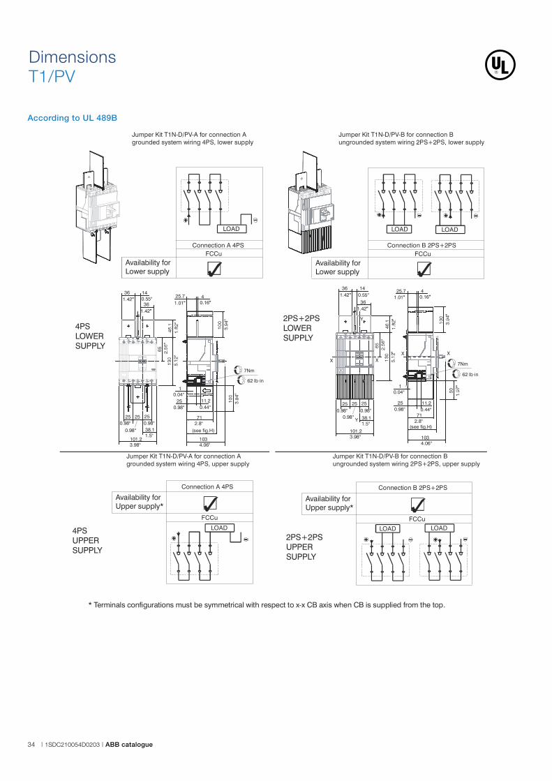
* Terminals configurations must be symmetrical with respect to x-x CB axis when CB is supplied from the top.
4PSUPPERSUPPLY
LOAD
FCCu
Connection A 4PS
Availability forUpper supply*
FCCuConnection A 4PS
LOAD
Availability forLower supply
Jumper Kit T1N-D/PV-B for connection B ungrounded system wiring 2PS+2PS, lower supply
2PS+2PSLOWERSUPPLY
36
36
Y
Y
X X
141.42" 0.55"
1.42"
250.98"
0.98"0.98"
1.5"
3.98"
25 25
38.1
101.2
25.7 41.01" 0.16"
4.06"
2.8"
0.04"
0.98" 0.44"
103
71
1
25 11.2
(see fig.H)
7Nm
X X
62 lb in·
4PSLOWERSUPPLY
36 14
361.42"
1.42"
0.55"
250.98"
0.98"0.98"
1.5"
3.98"
25 25
38.1
101.2
25.7 41.01" 0.16"
4.06"
2.8"
0.04"
0.98" 0.44"
103
71
1
25 11.2
7Nm
(see fig.H)
62 lb in·
2PS+2PSUPPERSUPPLY
LOAD
FCCu
Connection B 2PS+2PS
Availability forUpper supply*
LOAD
Availability forLower supply
Connection B 2PS+2PSFCCu
LOAD LOAD
Jumper Kit T1N-D/PV-A for connection A grounded system wiring 4PS, lower supply
Jumper Kit T1N-D/PV-B for connection B ungrounded system wiring 2PS+2PS, upper supply
Jumper Kit T1N-D/PV-A for connection A grounded system wiring 4PS, upper supply
Dimensions
T1/PV
According to UL 489B
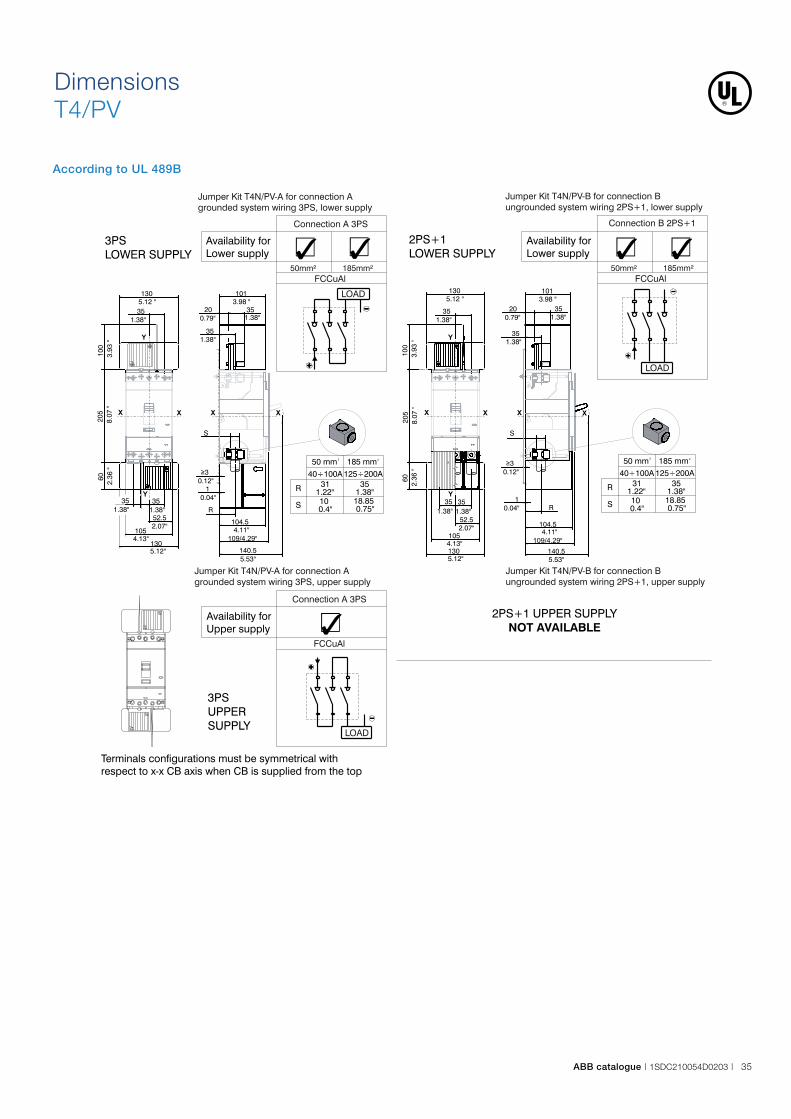
ABB catalogue | 1SDC210054D0203 | 35
Jumper Kit T4N/PV-B for connection B ungrounded system wiring 2PS+1, lower supply
Jumper Kit T4N/PV-A for connection A grounded system wiring 3PS, lower supply
Jumper Kit T4N/PV-B for connection B ungrounded system wiring 2PS+1, upper supply
Jumper Kit T4N/PV-A for connection A grounded system wiring 3PS, upper supply
R
S
35311.22"100.4"
40 00A÷1 125 00A÷2
1.38"18.850.75"
50mm²FCCuAl
LOAD
Availability forLower supply
185mm²
Connection A 3PS
50mm²FCCuAl
185mm²
Availability forLower supply
LOAD
Connection B 2PS+1
Terminals configurations must be symmetrical with respect to x-x CB axis when CB is supplied from the top
185 mm250 mm2
R
S
35311.22"100.4"
40 00A÷1 125 00A÷2
1.38"18.850.75"
185 mm250 mm2
1305.12 "
100
3.93
"
XX
3535
35
52.5
105
130
1.38"1.38"
1.38"
2.07"
4.13"
5.12"
205
8.07
"60
2.36
"
Y
Y
S
X X
109/4.29"
1013.98 "
R
35
35
20
140.5
104.5
1
3
1.38"
1.38"
0.79"
5.53"
4.11"
0.04"
0.12"
X X
109/4.29"
1013.98 "
R
S
35
35
20
140.5
104.5
1
3
1.38"
1.38"
0.79"
5.53"
4.11"
0.04"
0.12"
351.38"
1305.12 "
100
3.93
"XX
35
35
52.5
105
130
1.38"
1.38"
2.07"
4.13"
5.12"
205
8.07
"60
2.36
"
Y
Y
2PS+1LOWER SUPPLY
3PSLOWER SUPPLY
LOAD
2PS+1 UPPNOT AVAILABLE
ER SUPPLY
3PSUPPERSUPPLY
Availability forUpper supply
FCCuAl
Connection A 3PS
Le uniche configurazioni utilizzabili sono quelle riportate in questo documento.
The configurations here represented are the only ones available.
Dimensions
T4/PV
According to UL 489B

36 | 1SDC210054D0203 | ABB catalogue
Dimensions
T5/PV
According to UL 489B
Jumper FCCuAl Kit T5N/PV UL-A for connection A grounded system wiring 3PS, lower supply 225A
Jumper FCCuAl Kit T5N/PV UL-B for connection B ungrounded system wiring 2PS+1PS, lower supply 225A
100
3.93
"
205
8.07
"
74 2.91
"
46.51.83"
1656.5"
46.51.83"
1656.5"
1405.51"
XX
Y
Y
1024.02"
210.83"
461.81"
A
1024.02"
10.04"
30.12"
38.51.52"
140.55.53"
X
COMPARTMENT DEPTHPROFONDITA' QUADRO
X
23
0.9"
210.
83"
321.26"
Ø 18.85 0.74"
30.12"
10.04"
381.49"
A
104.54.11"
140.55.53"
1024.02"
210.83"
461.81"
X X
COMPARTMENT DEPTHPROFONDITA' QUADRO
1656.5"
46.51.83"
100
3.93
"
205
8.07
"60 2.36
"
= =
46.51.83"
46.51.83"
69.752.75"
1405.51"1656.5"
XX
Y
Y
FCCu
3PS
+
LOAD
-
Availability forLower supply
3PSLOWERSUPPLY
+
-
LOAD
FCCu
2PS+1PS
Availability forLower supply
2PS+1PSLOWERSUPPLY
LOAD
+
-
FCCu
3PS
3PSUPPERSUPPLY
Availability forUpper supply
UPPER SUPPLY NOT AVAILABLE
23
0.9"
210.
83"
321.26"
Ø 18.85 0.74"

ABB catalogue | 1SDC210054D0203 | 37
Jumper FCCuAl Kit T5N/PV UL-A for connection A grounded system wiring 3PS, lower supply 250A
Jumper FCCuAl Kit T5N/PV UL-B for connection B ungrounded system wiring 2PS+1PS, lower supply 250A
271"
240.
95"
36.51.44"
Ø 21.5 0.85"
100
3.93
"
205
8.07
"
74 2.91
"
46.51.83"
1656.5"
29.2
51.
15"
46.51.83"
1656.5"
1405.51"
29.2
51.
15"
XX
Y
Y
1024.02"
210.83"
461.81"
A
1024.02"
10.04"
30.12"
38.51.52"
140.55.53"
X
COMPARTMENT DEPTHPROFONDITA' QUADRO
X
30.12"
10.04"
381.49"
A
104.54.11"
140.55.53"
1024.02"
210.83"
461.81"
X X
COMPARTMENT DEPTHPROFONDITA' QUADRO
1656.5"
46.51.83"
100
3.93
"
205
8.07
"60 2.36
"
= =
46.51.83"
46.51.83"
69.752.75"
1405.51"1656.5"
XX
Y
Y
FCCu
3PS
+
LOAD
-
Availability forLower supply
3PSLOWERSUPPLY
+
-
LOAD
FCCu
2PS+1PS
Availability forLower supply
2PS+1PSLOWERSUPPLY
LOAD
+
-
FCCu
3PS
Availability forUpper supply
3PSUPPERSUPPLY
UPPER SUPPLY NOT AVAILABLE
271"
240.
95"
36.51.44"
Ø 21.5 0.85"

38 | 1SDC210054D0203 | ABB catalogue
According to UL 489B
Dimensions
T5/PV
Jumper FCCu Kit T5N/PV UL-A for connection A grounded system wiring 3PS, lower supply 300A-400A
Jumper FCCu Kit T5N/PV UL-B for connection B ungrounded system wiring 2PS+1PS, lower supply 300A-400A
250.98"
2 x Ø 21.5 0.85"
28
1.1"
56,5
2.22
"
100
3.93
"
205
8.07
"
74 2.91
"
46.51.83"
1656.5"
29.2
51.
15"
46.51.83"
1656.5"
1405.51"
29.2
51.
15"
XX
Y
Y
1024.02"
210.83"
461.81"
A
1024.02"
10.04"
30.12"
38.51.52"
250.98"
Ø21.50.85"
140.55.53"
X
COMPARTMENT DEPTHPROFONDITA' QUADRO
X
250.98"
2 x Ø 21.5 0.85"
28
1.1"
56,5
2.22
"
30.12"
10.04"
381.49"
250.98"
Ø21.50.85"
A
104.54.11"
140.55.53"
1024.02"
210.83"
461.81"
X X
COMPARTMENT DEPTHPROFONDITA' QUADRO
1656.5"
46.51.83"
100
3.93
"
205
8.07
"60 2.36
"= =
46.51.83"
46.51.83"
69.752.75"
1405.51"1656.5"
XX
Y
Y
A
107
115 115
107
B C
64.5
60.5
CON MOSTRINAWITH FLANGE
2.38"
2.54"
4.21"
4.53"4.53"
4.21"
(mm)
(inch)
WITHOUT FLANGESENZA MOSTRINA
WITH FLANGECON MOSTRINA
WITHOUT FLANGESENZA MOSTRINA
Label that indicatestype of jumper kitinstalled on breaker
FCCu
3PS
+
LOAD
-
Availability forLower supply
3PSLOWERSUPPLY
+
-
LOAD
FCCu
2PS+1PS
Availability forLower supply
2PS+1PSLOWERSUPPLY
UPPER SUPPLY NOT AVAILABLE
LOAD
+
-
FCCu
3PS
Availability forUpper supply
3PSUPPERSUPPLY
46.51.83"
176
6.93
"
Ø5.5 (M5)0.22"
C
B
A
= =
= =
= =
XX
Y
Y
17.70 lb·in2 Nm
297
11.6
9"=
=
933.66"= =
Ø5.5 (M5)0.22"
only for 300A-400A

ABB catalogue | 1SDC210054D0203 | 39
Busbar Jumper ES Kit T5N/PV UL-A for connection A grounded system wiring 3PS, lower supply
Busbar Jumper ES Kit T5N/PV UL-B for connection B ungrounded system wiring 2PS+1PS, lower supply
40
1.57"
60.24"
Ø 110.43"
40
1.57"
60.24"
Ø 110.43"
57.752.27"
1656.5"
200
7.87
"
205
8.07
"20
07.
87"
42.2
51.
66"
42.2
51.
66"
57.752.27"
Ø110.43"
X X
= =
Y
Y
X
1
30.12"
210.83"
A
0.04" 1024.02"
311.22"
60.24"
140.55.53"
461.81"
1024.02"
X
PROFONDITA' QUADROCOMPARTMENT DEPTH
200
7.87
"
57.752.27"
==
1656.5"
205
8.07
"20
07.
87"
57.752.27"
57.752.27"
42.2
51.
66"
42.2
51.
66"
Ø110.43"
1405.51"
X X
Y
Y
461.81"
140.55.53"
A30.12"
210.83"
1024.02"
311.22"
60.24"
X X
COMPARTMENT DEPTHPROFONDITA' QUADRO
NO! OK
ES
3PS
+
LOAD
-
Availability forLower supply
3PSLOWERSUPPLY
+
-
LOAD
ES
2PS+1PS
Availability forLower supply
2PS+1PSLOWERSUPPLY
LOAD
+
-
ES
3PS
3PSUPPERSUPPLY
Availability forUpper supply
UPPER SUPPLY NOT AVAILABLE
XX
Y
Y
A
B
A
B
A
A
B

40 | 1SDC210054D0203 | ABB catalogue
Availability forLower supply
FCCuAl
4PS
LOAD
4PSLOWERSUPPLY
Jumper Kit T6N/PV-A for connection A grounded system wiring 4PS, lower supply
Jumper Kit T6N/PV-B for connection B ungrounded system wiring 2PS+2PS, lower supply
600A3x300 Kcmil
LOAD LOAD
Availability forLower supply
FCCuAl
2PS+2PS
2PS+2PSLOWERSUPPLY
84.5
3.3 "
453
17.8
"
84.5
3.3 "
134
5.3"
X
32012.6 "
32012.6"
1204.7"
702.8"
28011"
1204.7""
702.8""
95 3.7"
268
10.5
"15
05.
9 "15
05.
9 "15
05.
9 " = =
1204.7
702.8
91 3.6 "
X
Y
Y
32012.6 "
28011"
150
5.91
"
95 3.7"
32012.6 "
150
5.91
"15
05.
92"
= =
702.76"
268
10.5
"
70 2.76
"45
317
.84 "
84.5
3.33
"
1204.72"
134
5.28
"
X X
702.76"
702.76"
Y
Y
95.53.76"
481.89"
24.10.95"
153.
56
"
173.
36.
8 "
104.54.1"108
4.25"1616.3"
30.12"
20.08"
105
4.1"
1164.6"
X X
441.
73"
95.53.76"
24.10.95"
72.12.84"
181
7.1"
105
4.1 "
1616.3"
1084.25"
20.08"
104.54.1"
30.12 "
1164.6 "
X X
441.
73"
600A3x300 Kcmil
44
63.5
47.5
Ø 9120 0.79
"
1.87"1.73"
2.5"
0.75"
44
63.5
47.5
Ø 9120 0.79
"
1.87"1.73"
2.5"
0.75"
UPPNOT AVAILABLE
ER SUPPLY UPPNOT AVAILABLE
ER SUPPLY
Dimensions
T6/PV 600A
According to UL 489B

ABB catalogue | 1SDC210054D0203 | 41
LOAD LOAD
Availability forLower supply
EF
2PS+2PS
2PS+2PSLOWERSUPPLY
Availability forLower supply
EF
4PS
LOAD
4PSLOWERSUPPLY
4PS solution, terminals for Lower Supply 2PS+2PS solutions, terminals for Lower Supply
UPPNOT AVAILABLE
ER SUPPLY UPPNOT AVAILABLE
ER SUPPLY
50
14Ø
8
20
2"
0.6"0.79
"
0.32"
50
14Ø
8
20
2"
0.6"0.79
"
0.32"
32012.6"
702.8"
702.8"
1204.7"
134
5.3
"84
.53.
3"
150
5.9
"15
05.
9"
150
5.9
"
268
10.6
"94 3.7
"
125.
54.
9"
150
5.9
"
27911"
Ø 410.6"
134
105.
54.
2"
XX
702.8"
5.3
"
Y
Y
104.54.1"
1084.25"
20.08"
1616.3"
105
4.1"
1164.6"
95.53.76"
72.12.84"
24.10.95"
284
11.2
"
30.12 "
50.62"
X X
44 1.73
"
502"
32012.6"
702.8"
702.8"
1204.7"
134
5.3
"84
.53.
3"
150
5.9
"15
05.
9"
150
5.9
"
268
10.6
"94 3.7
"
125.
54.
9"
150
5.9
"
27911"
Ø 410.6"
134
105.
54.
2"
XX
702.8"
5.3
"
Y
Y
104.54.1"
1084.25"
20.08"
1616.3"
105
4.1"
1164.6"
95.53.76"
72.12.84"
24.10.95"
284
11.2
"
30.12 "
50.62"
X X
44 1.73
"
Dimensions
T6/PV 800A
According to UL 489B

42 | 1SDC210054D0203 | ABB catalogue
Dimensions
T7/PV
According to UL 489B
FCCuAlConnection A 4PS
LOAD
Connection B 2PS+2PSFCCuAl
LOAD LOAD
4PSLOWERSUPPLY
2PS+2PSLOWERSUPPLY
Availability forLower supply*
Availability forLower supply*
F F
LOAD
FCCuAl
Connection A 4PS
LOAD
FCCuAl
Connection B 2PS+2PS
LOAD
Availability forUpper supply
Availability forUpper supply
2PS+2PSUPPERSUPPLY
4PSUPPERSUPPLY
F F

ABB catalogue | 1SDC210054D0203 | 43
Kit T7N-D/PV-B for connection B ungrounded system wiring 2PS+2PSKit T7N-D/PV-A for connection A grounded system wiring 4PS
229
9.02
"
191.
57.
54 "
334
" 51.31
X
X
458
18.0
3 "
268
10.5
5 "13
45.
28 "
200
7.87
"
702.76 "
702.76 "
702.76 "
1054.13 "
200
7.87
"
204
8.03
"67.252.65 "
35.751.41"
A
X X X
43 Nm
380 lb·in
702.76 "
702.76 "
702.76 "
1054.14 "
134
5.28
"26
810
.55
"20
07.
87 "
458
18.0
3 "
X X
35.751.41 "
67.252.65 "
A
204
8.03
"
X X
43 Nm
380 lb·in
5.191" 45.7
229
" 20.9
X
X
CON MOSTRINAWITH FLANGE
SENZA MOSTRINAWITHOUT FLANGE
Amm 165 170
in 6.50" 6.69"
CON MOSTRINAWITH FLANGE
SENZA MOSTRINAWITHOUT FLANGE
Amm 165 170
in 6.50" 6.69"
FCCuAl - Example for Upper Supply FCCuAl - Example for Upper Supply
* LOWER SUPPL Y - According to indicated schemes, terminals configurations must be symmetrical respect to x-x CB axis
CON MOSTRINAWITH FLANGE
SENZA MOSTRINAWITHOUT FLANGE
Amm 125...164 170
in 4.9"...6.5" 6.69"
CON MOSTRINAWITH FLANGE
SENZA MOSTRINAWITHOUT FLANGE
Amm 125...164 170
in 4.9"...6.5" 6.69"
F - Example for Upper Supply F - Example for Upper Supply
229
9.02
"
134
5.28
"
334
" 51.31
X
X
458
18.0
3 "
268
10.5
5 "13
45.
28 "
200
7.87
"
702.76 "
702.76 "
702.76 "
1054.13 "
200
7.87
"
204
8.03
"
A
X X X
14.5
24
1010
702.76 "
702.76 "
702.76 "
1054.14 "
134
5.28
"26
810
.55
"20
07.
87 "
458
18.0
3 "
X X
A
204
8.03
"
X X
14.5
24
1010
134
" 82.5
229
" 20.9
X
X

44 | 1SDC210054D0203 | ABB catalogue
Codes
Tmax PV IEC 1100V & 1500V switch-disconnectorsBreakers
Code Description
1SDA069816R1 T1D/PV 160 4p F FC Cu 1100V DC
1SDA069822R1 T3D/PV 200 4p F FC Cu 1100V DC
1SDA069823R1 T4D/PV 250 4p F F 1100V DC
1SDA069824R1 T5D/PV 500 4p F F 1100V DC
1SDA069825R1 T6D/PV 800 4p F F 1100V DC
1SDA069826R1 T7D/PV 1250 4p F F 1100V DC
1SDA069827R1 T7D/PV 1250 4p F F M 1100V DC
1SDA069828R1 T7D/PV 1600 4p F F 1100V DC
1SDA069829R1 T7D/PV 1600 4p F F M 1100V DC
1SDA073559R1 T4D/PV-E 250 4p F F 1500V DC
1SDA076898R1 T5D/PV-E 500 4p FF 1500V DC
1SDA073560R1 T7D/PV-E 1250 4p F F M 1500V DC
1SDA073561R1 T7D/PV-E 1600 4p F F M 1500V DC
Kit Jumpers
Code Description
1SDA069876R1 KIT 2 JUMPER 2+2PS T1D/PV 160 4p
1SDA069877R1 KIT 3 JUMPER 4PS T1D/PV 160 4p
1SDA076162R1 KIT 2JUMPER U 2+2PS T3D/PV 200
1SDA076163R1 KIT 3JUMPER U 4PS T3D/PV 200
1SDA070454R1 KIT 2JUMPER U 2+2PS T4D/PV 250
1SDA070455R1 KIT 3JUMPER U 4PS T4D/PV 250
1SDA070456R1 KIT 2JUMPER U 2+2PS T5D/PV 500
1SDA070457R1 KIT 3JUMPER U 4PS T5D/PV 500
1SDA076899R1 KIT 2JUMPER U 2+2PS T5D/PV-E 500 1500V DC
1SDA070491R1 KIT 2JUMPER U 2+2PS T6D/PV 800
1SDA070492R1 KIT 3JUMPER U 4PS T6D/PV 800
1SDA070429R1 KIT JUMPER U 2+2PS T7D/PV 1250
1SDA070431R1 KIT JUMPER U 2+2PS T7D/PV 1600
1SDA070430R1 KIT JUMPER U 4PS T7D/PV 1250
1SDA070432R1 KIT JUMPER U 4PS T7D/PV 1600
Tmax PV can be accessoried with Tmax series accessories, except for the following exceptions:
Frame size Incompatibilities
T1D PV Interlocks, KLC, PLL
T3D PV Interlocks, KLC, PLL
T4D PV Interlocks
T5D PV Interlocks
T6D PV Interlocks
T7D PV Interlocks
T7D PV M Interlocks
Accessories part number, wirings and data can be found in the Tmax IEC Technical Catalogue and Tmax UL489 Technical Catalogue.
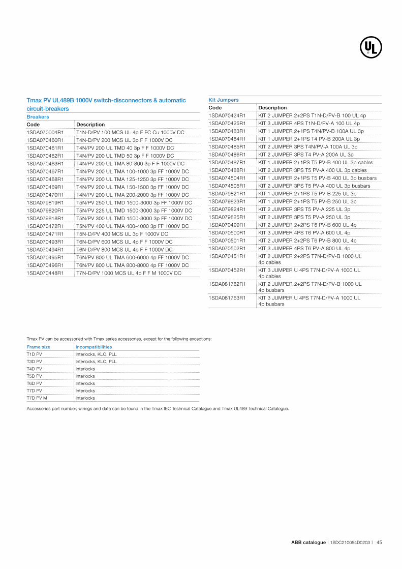
ABB catalogue | 1SDC210054D0203 | 45
Tmax PV UL489B 1000V switch-disconnectors & automatic circuit-breakersBreakers
Code Description
1SDA070004R1 T1N-D/PV 100 MCS UL 4p F FC Cu 1000V DC
1SDA070460R1 T4N-D/PV 200 MCS UL 3p F F 1000V DC
1SDA070461R1 T4N/PV 200 UL TMD 40 3p F F 1000V DC
1SDA070462R1 T4N/PV 200 UL TMD 50 3p F F 1000V DC
1SDA070463R1 T4N/PV 200 UL TMA 80-800 3p F F 1000V DC
1SDA070467R1 T4N/PV 200 UL TMA 100-1000 3p FF 1000V DC
1SDA070468R1 T4N/PV 200 UL TMA 125-1250 3p FF 1000V DC
1SDA070469R1 T4N/PV 200 UL TMA 150-1500 3p FF 1000V DC
1SDA070470R1 T4N/PV 200 UL TMA 200-2000 3p FF 1000V DC
1SDA079819R1 T5N/PV 250 UL TMD 1500-3000 3p FF 1000V DC
1SDA079820R1 T5N/PV 225 UL TMD 1500-3000 3p FF 1000V DC
1SDA079818R1 T5N/PV 300 UL TMD 1500-3000 3p FF 1000V DC
1SDA070472R1 T5N/PV 400 UL TMA 400-4000 3p FF 1000V DC
1SDA070471R1 T5N-D/PV 400 MCS UL 3p F 1000V DC
1SDA070493R1 T6N-D/PV 600 MCS UL 4p F F 1000V DC
1SDA070494R1 T6N-D/PV 800 MCS UL 4p F F 1000V DC
1SDA070495R1 T6N/PV 800 UL TMA 600-6000 4p FF 1000V DC
1SDA070496R1 T6N/PV 800 UL TMA 800-8000 4p FF 1000V DC
1SDA070448R1 T7N-D/PV 1000 MCS UL 4p F F M 1000V DC
Kit Jumpers
Code Description
1SDA070424R1 KIT 2 JUMPER 2+2PS T1N-D/PV-B 100 UL 4p
1SDA070425R1 KIT 3 JUMPER 4PS T1N-D/PV-A 100 UL 4p
1SDA070483R1 KIT 1 JUMPER 2+1PS T4N/PV-B 100A UL 3p
1SDA070484R1 KIT 1 JUMPER 2+1PS T4 PV-B 200A UL 3p
1SDA070485R1 KIT 2 JUMPER 3PS T4N/PV-A 100A UL 3p
1SDA070486R1 KIT 2 JUMPER 3PS T4 PV-A 200A UL 3p
1SDA070487R1 KIT 1 JUMPER 2+1PS T5 PV-B 400 UL 3p cables
1SDA070488R1 KIT 2 JUMPER 3PS T5 PV-A 400 UL 3p cables
1SDA074504R1 KIT 1 JUMPER 2+1PS T5 PV-B 400 UL 3p busbars
1SDA074505R1 KIT 2 JUMPER 3PS T5 PV-A 400 UL 3p busbars
1SDA079821R1 KIT 1 JUMPER 2+1PS T5 PV-B 225 UL 3p
1SDA079823R1 KIT 1 JUMPER 2+1PS T5 PV-B 250 UL 3p
1SDA079824R1 KIT 2 JUMPER 3PS T5 PV-A 225 UL 3p
1SDA079825R1 KIT 2 JUMPER 3PS T5 PV-A 250 UL 3p
1SDA070499R1 KIT 2 JUMPER 2+2PS T6 PV-B 600 UL 4p
1SDA070500R1 KIT 3 JUMPER 4PS T6 PV-A 600 UL 4p
1SDA070501R1 KIT 2 JUMPER 2+2PS T6 PV-B 800 UL 4p
1SDA070502R1 KIT 3 JUMPER 4PS T6 PV-A 800 UL 4p
1SDA070451R1 KIT 2 JUMPER 2+2PS T7N-D/PV-B 1000 UL
4p cables
1SDA070452R1 KIT 3 JUMPER U 4PS T7N-D/PV-A 1000 UL
4p cables
1SDA081762R1 KIT 2 JUMPER 2+2PS T7N-D/PV-B 1000 UL
4p busbars
1SDA081763R1 KIT 3 JUMPER U 4PS T7N-D/PV-A 1000 UL
4p busbars
Tmax PV can be accessoried with Tmax series accessories, except for the following exceptions:
Frame size Incompatibilities
T1D PV Interlocks, KLC, PLL
T3D PV Interlocks, KLC, PLL
T4D PV Interlocks
T5D PV Interlocks
T6D PV Interlocks
T7D PV Interlocks
T7D PV M Interlocks
Accessories part number, wirings and data can be found in the Tmax IEC Technical Catalogue and Tmax UL489 Technical Catalogue.


1S
DC
2100
54D
0203
- 2
015.
10
Contact us
ABB SACEA division of ABB S.p.A.L.V. BreakersVia Pescaria, 524123 BergamoPhone: +39 035 395.549Fax: +39 035 395.284
www.abb.com
The data and illustrations are not binding. We reserve the right to modify the contents of this document on the basis of technical development of the products, without prior notice.
Copyright 2015 ABB. All rights reserved.
Stay tuned. Discover more by visiting the webpagesreserved to Tmax PV and be always up-to-date with the latest edition of the catalogue.