CAST STEEL VALVES - Bonney Forgecad.bonneyforge.com/Asset/CSV.pdf · 2 Bonney Forge – The Name...
20
CAST STEEL VALVES
Transcript of CAST STEEL VALVES - Bonney Forgecad.bonneyforge.com/Asset/CSV.pdf · 2 Bonney Forge – The Name...

CAST STEEL VALVES
Corporate Overview ................................................................................ 2, 3
Quality Assurance ................................................................................... 4, 5
How To Order ........................................................................................... 6-8
Gate Valves ............................................................................................ 9-11
Globe Valves ....................................................................................... 12-14
Swing Check Valves ............................................................................ 15-17
Engineering Specifications .................................................................... 18-29
Special Valves & Features .......................................................... 18, 19
Bypass & Drain Connection ............................................................. 20
Butt-Welding Ends ........................................................................... 21
Flange Dimensions .................................................................... 22, 23
Ring Joint Facings ..................................................................... 24, 25
Standard Class Pressure Temperature Ratings ............................ 26-28
Storage, Installation & Maintenance ............................................ 29-34
Terms & Conditions ......................................................................... 37
Table Of COnTenTs
BONNEY FORGE (SHANGHAI) LIMITEDNO.118-28 XINDAN ROAD, QINGPU EXPORT PROCESSING ZONE
SHANGHAI, CHINA 201706
BONNEY FORGE CORPORATE HEADQUARTERS MANUFACTURING/SALES CENTER/WAREHOUSE
14496 CROGHAN PIKE • P.O. BOX 330 • MT. UNION, PA 17066 (814) 542-2545 • (800) 231-0655
(800) 345-7546 • FAX (814) 542-9977 www.bonneyforge.com • [email protected]
BONNEY FORGE CORPORATE HEADQUARTERS MT. UNION, PA

2
Bonney Forge – The Name You Can Trust for Cast Steel ValvesFor decades, Bonney Forge forged steel valves and piping components have defined “state-of-the-art” in quality, design and manufacturing. Today, our extensive product line of cast steel valves leads the way.
Since 2002, Bonney Forge has been manufacturing its Cast Steel Valves in Shanghai, China. Bonney Forge Shanghai, manufactures a full line of Cast Steel Gate, Globe and Check Valves designed for ASME pressures 150# thru 1500# and temperature ratings as low as -50°F. Our technicians can also customize a configuration to fit your
needs. Bonney Forge customers have a complete choice of trim and body materials, bypasses and connectors including: lift indicators, limit microswitches, pneumatic and electric actuators, bevel gearings, chain wheels, extension stems, floor stands, levers and dashpots.
Bonney Forge Shanghai also meets stringent design and quality guidelines set and directed by Bonney Forge’s corporate engineering department at its corporate location in Mt. Union, Pennsylvania, USA. Bonney Forge Shanghai has also earned
a single-sOurCe sOluTiOn
forged steel valves, cast steel valves, forged fittings, branch connections and other related products to satisfy our customer’s expectations.
To be cost effective through Total Quality performance of these operations, and thus provide the resources required to support our commitment to improve our products, processes and customer services.
To be a law abiding corporate citizen respecting the rights of individuals, contributing to the needs of the community and conserving the state of the environment.
the ISO 9001:2008, PED CE Mark, API 6D, and API 600 Certificates.
We’re Here for YouBonney Forge is committed to manufacturing excellence and is focused on meeting our customers’ needs. This catalog offers a vast amount of product information and specifications. In the event that you need additional information or technical assistance please call our friendly and knowledgeable customer service team at (800) 231-0655 or visit our website at www.bonneyforge.com.
Our MissionTo be, today and in the future, the recognized leader in our industry, marketing and manufacturing
3

QualiTy assuranCe
4 5
TestingBonney Forge products are manufactured and tested in strict accordance to ASTM, ASME, API and other industry codes and specifications as applicable.
Material Certifications are available upon request to the applicable ASTM/ASME material specifications for all Bonney Forge Valve bodies and bonnets.
Modern machining equipment plus rigid inspection procedures of all parts assures dimensional accuracy of every part. Quality Assurance procedures include, 100% hydrostatic and pneumatic testing of all valves in full conformance to applicable API standards and industry codes.
Chemical and mechanical properties of every Bonney Forge cast steel valve are fully traceable to the original casting heat lot.
Material Safety Data SheetsMaterial Safety Data Sheets (MSDS) are required for hazardous chemicals under the Occupational Safety and Health Administration (OSHA) Hazard Communication Standard 29 CFR 1910.1200. Bonney Forge Corporation has determined that its valve and fitting products are “articles”, as defined by this standard, and therefore do not require material safety data sheets.
Certificates Also, Bonney Forge Shanghai is fully qualified and maintains the ISO 9001 2008, PED CE Mark, API 6D and API 600 certifications, as indicated below.
Manufacturing CapabilitiesThe Bonney Forge Shanghai facilities are located in Shanghai, China and are in full accordance with ISO 9001 and CE Mark certifications.
HOw TO Order/speCify CasT sTeel ValVes
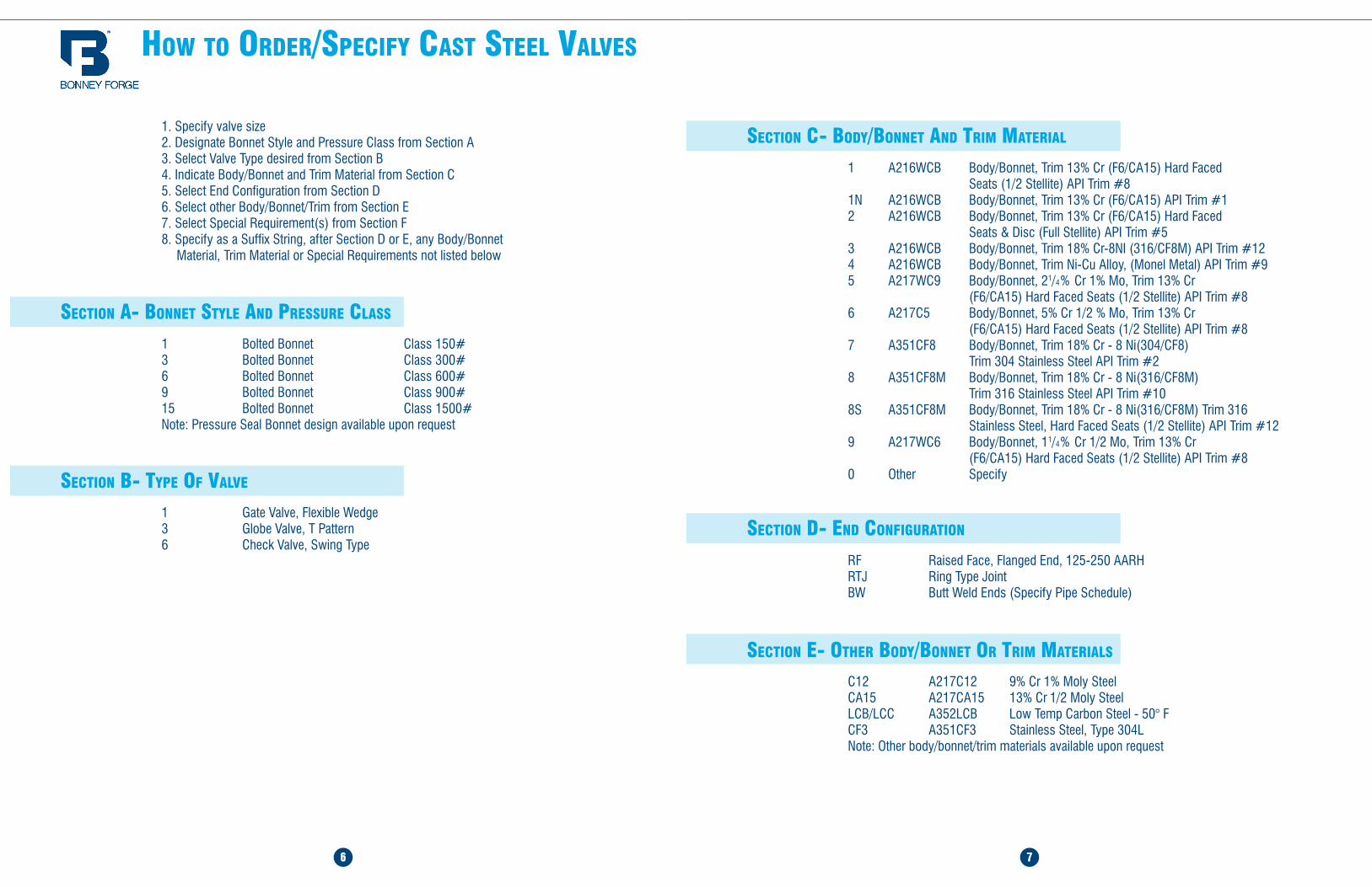
1. Specify valve size 2. Designate Bonnet Style and Pressure Class from Section A 3. Select Valve Type desired from Section B 4. Indicate Body/Bonnet and Trim Material from Section C 5. Select End Configuration from Section D 6. Select other Body/Bonnet/Trim from Section E 7. Select Special Requirement(s) from Section F 8. Specify as a Suffix String, after Section D or E, any Body/Bonnet Material, Trim Material or Special Requirements not listed below
seCTiOn a- bOnneT sTyle and pressure Class
1 Bolted Bonnet Class 150# 3 Bolted Bonnet Class 300# 6 Bolted Bonnet Class 600# 9 Bolted Bonnet Class 900# 15 Bolted Bonnet Class 1500# Note: Pressure Seal Bonnet design available upon request
seCTiOn b- Type Of ValVe
1 Gate Valve, Flexible Wedge 3 Globe Valve, T Pattern 6 Check Valve, Swing Type
6 7
seCTiOn C- bOdy/bOnneT and Trim maTerial
1 A216WCB Body/Bonnet, Trim 13% Cr (F6/CA15) Hard Faced Seats (1/2 Stellite) API Trim #8 1N A216WCB Body/Bonnet, Trim 13% Cr (F6/CA15) API Trim #1 2 A216WCB Body/Bonnet, Trim 13% Cr (F6/CA15) Hard Faced Seats & Disc (Full Stellite) API Trim #5 3 A216WCB Body/Bonnet, Trim 18% Cr-8NI (316/CF8M) API Trim #12 4 A216WCB Body/Bonnet, Trim Ni-Cu Alloy, (Monel Metal) API Trim #9 5 A217WC9 Body/Bonnet, 21/4% Cr 1% Mo, Trim 13% Cr (F6/CA15) Hard Faced Seats (1/2 Stellite) API Trim #8 6 A217C5 Body/Bonnet, 5% Cr 1/2 % Mo, Trim 13% Cr (F6/CA15) Hard Faced Seats (1/2 Stellite) API Trim #8 7 A351CF8 Body/Bonnet, Trim 18% Cr - 8 Ni(304/CF8) Trim 304 Stainless Steel API Trim #2 8 A351CF8M Body/Bonnet, Trim 18% Cr - 8 Ni(316/CF8M) Trim 316 Stainless Steel API Trim #10 8S A351CF8M Body/Bonnet, Trim 18% Cr - 8 Ni(316/CF8M) Trim 316 Stainless Steel, Hard Faced Seats (1/2 Stellite) API Trim #12 9 A217WC6 Body/Bonnet, 11/4% Cr 1/2 Mo, Trim 13% Cr (F6/CA15) Hard Faced Seats (1/2 Stellite) API Trim #8 0 Other Specify
seCTiOn d- end COnfiguraTiOn
RF Raised Face, Flanged End, 125-250 AARH RTJ Ring Type Joint BW Butt Weld Ends (Specify Pipe Schedule)
seCTiOn e- OTHer bOdy/bOnneT Or Trim maTerials
C12 A217C12 9% Cr 1% Moly Steel CA15 A217CA15 13% Cr 1/2 Moly Steel LCB/LCC A352LCB Low Temp Carbon Steel - 50° F CF3 A351CF3 Stainless Steel, Type 304L Note: Other body/bonnet/trim materials available upon request
D I M E N S I O N A L S P E C I F I C A T I O N S
SIZE inch mm
2 50
2.5 65
3 80
4 100
5 130
6 150
8 200
10 250
12 300
14 350
16 400
18 450
20 500
24 600
L inch mm
7.00 177.80
7.50 190.50
8.00 203.20
9.00 228.60
10.00 254.00
10.50 266.70
11.5 292.10
13.00 330.20
14.00 355.60
15.00 381.00
16.00 406.40
17.00 431.80
18.00 457.20
20.00 508.00
L1 inch mm
8.50 215.90
9.50 241.30
11.12 282.45
12.00 304.80
15.00 381.00
15.88 403.35
16.50 419.10
18.00 457.20
19.75 501.65
22.50 571.50
24.00 609.60
26.00 660.40
28.00 711.20
32.00 812.80
L2 inch mm
7.50 190.50
8.00 203.20
8.50 215.90
9.50 241.30
10.50 266.7
11.00 279.40
12.00 304.80
13.50 342.90
14.50 368.30
15.50 393.70
16.50 419.10
17.50 444.50
18.50 469.90
20.50 520.70
W inch mm
8 200
8 200
10 250
10 250
10 250
12 300
14 350
16 400
20 500
20 500
24 600
25 640
26 650
30 750
W1 inch mm - - - - - - 12.0
30512.2 305
12.2 305
12.2 305
12.2 310
18.1 460
18.1 460
18.1 460
H (OPEN) inch mm
16.65 423
19.50 495
20.50 520
23.50 596
28.00 711
29.80 759
39.00 995
26.50 1180
56.00 1432
60.50 1535
71.30 1811
79.00 2009
87.80 2230
104.00 2641
H1 (GEAR) inch mm - - - - - - 42.13
107050.75 1289
59.41 1509
63.54 1614
72.44 1840
79.21 2012
85.83 2180
100.79 2560
A inch mm - - - - - - 8.66
2208.66 220
8.66 220
14.17 360
14.17 360
14.17 360
16.18 411
16.18 411
WT (RF) lb kg
47 21
62 28
80 36
118 53
133 60
187 84
309 139
447 201
711 320
956 430
1218 548
1653 744
2482 1117
3258 1466
WT (BW) lb kg
40 18
47 21
67 30
98 44
120 54
169 76
280 126
398 179
673 303
884 398
1131 509
1578 710
2393 1077
3169 1426
WT (RF & GO) lb kg - - - - - - 358
161496 223
760 342
1000 450
1262 568
1720 774
2549 1147
3324 1496
WT (BW & GO) lb kg - - - - - - 329
148447 201
722 325
929 418
1176 529
1644 740
2460 1107
3236 1456
CV Factors - 410 710 1300 - 3110 5720 8935 13350 - 21560 36091 47615 67862
HOw TO Order/speCify CasT sTeel ValVes
seCTiOn f- mOdifiCaTiOns/speCial reQuiremenTs
8
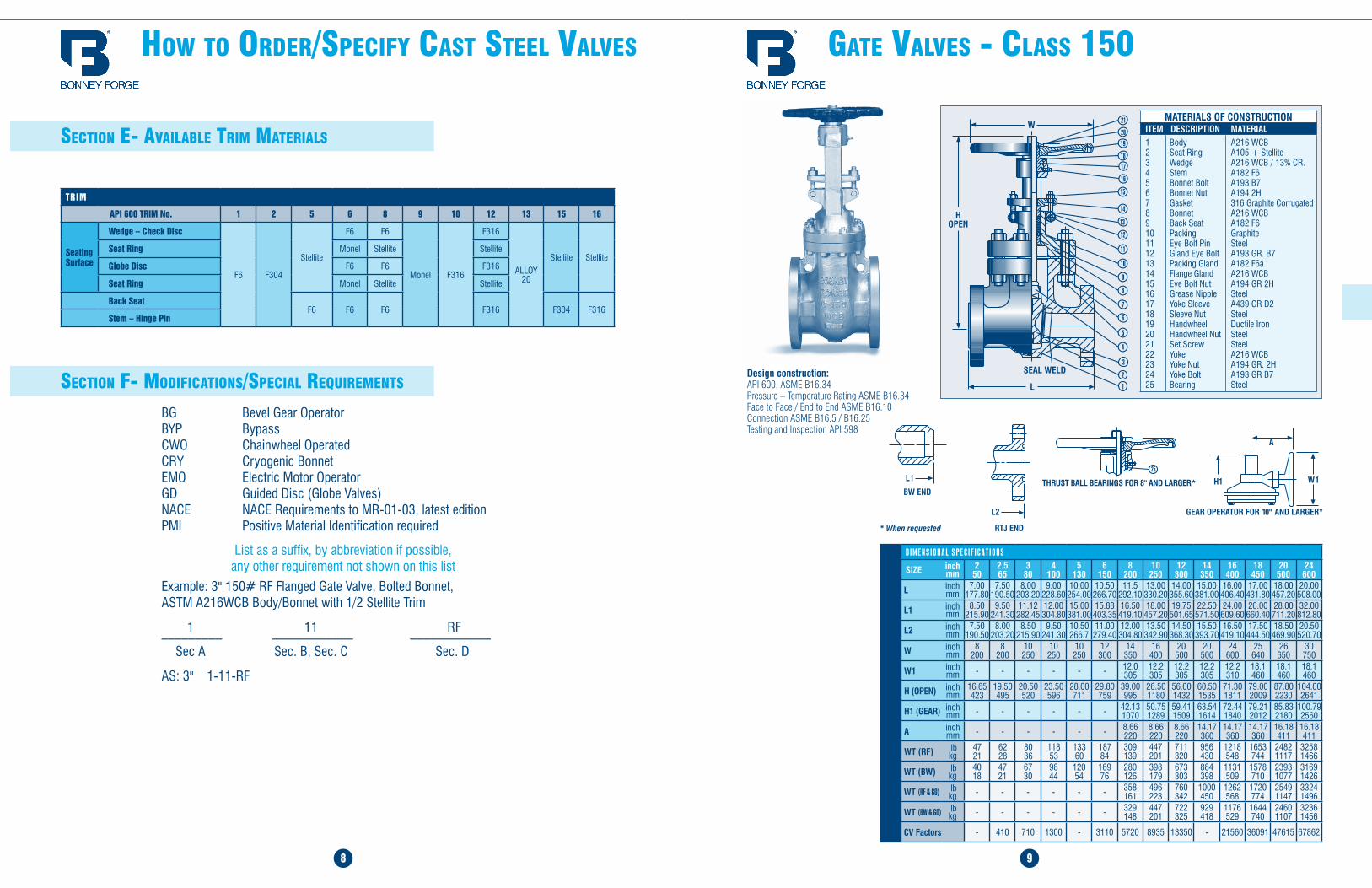
BG Bevel Gear Operator BYP Bypass CWO Chainwheel Operated CRY Cryogenic Bonnet EMO Electric Motor Operator GD Guided Disc (Globe Valves) NACE NACE Requirements to MR-01-03, latest edition PMI Positive Material Identification required
List as a suffix, by abbreviation if possible, any other requirement not shown on this list
Example: 3" 150# RF Flanged Gate Valve, Bolted Bonnet, ASTM A216WCB Body/Bonnet with 1/2 Stellite Trim
1 11 RF _________ ____________ ____________ Sec A Sec. B, Sec. C Sec. D
AS: 3" 1-11-RF
seCTiOn e- aVailable Trim maTerials
gaTe ValVes - Class 150
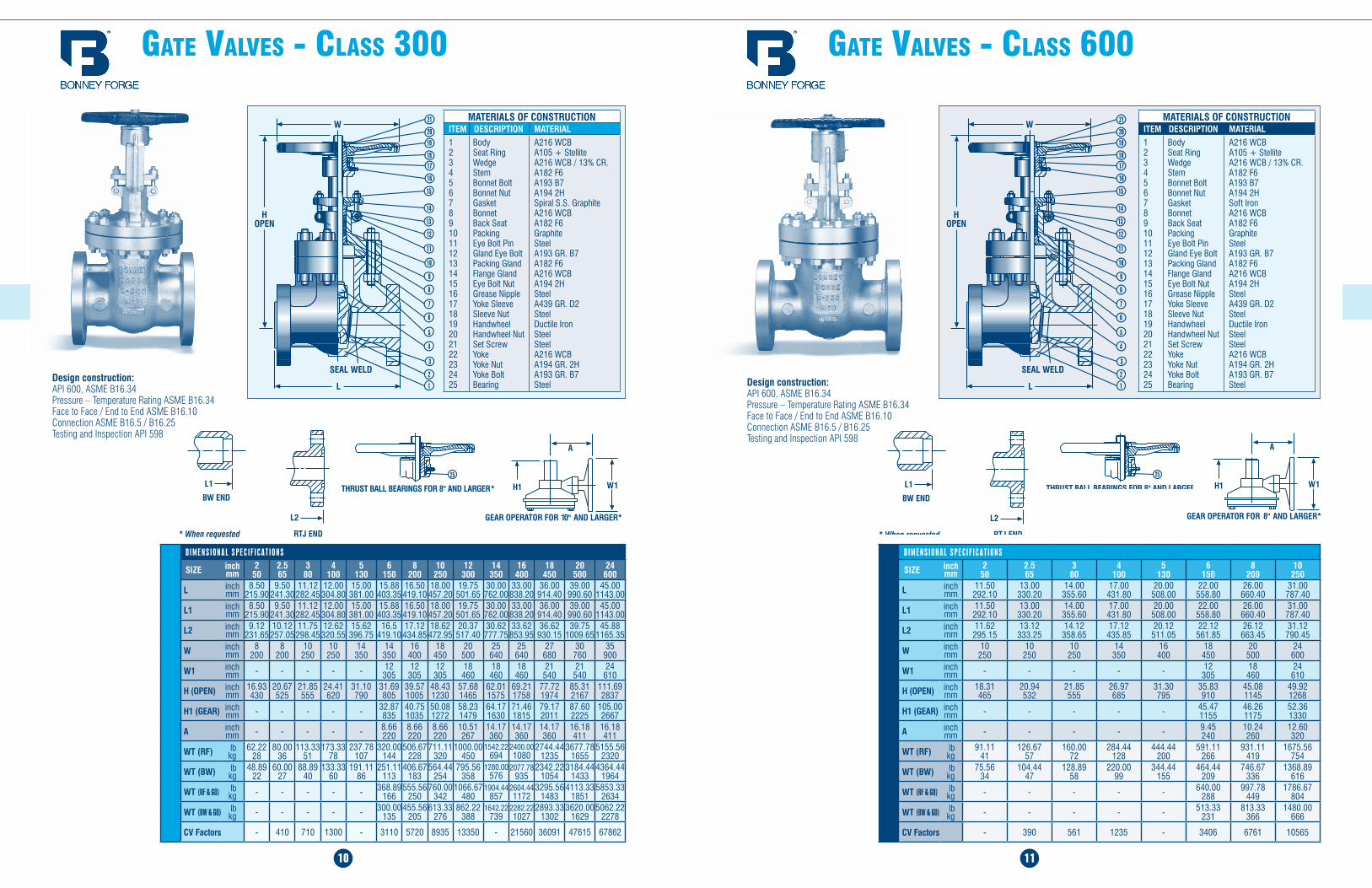
Design construction:API 600, ASME B16.34 Pressure – Temperature Rating ASME B16.34 Face to Face / End to End ASME B16.10 Connection ASME B16.5 / B16.25Testing and Inspection API 598
9
MATERIALS OF CONSTRUCTIONITEM DESCRIPTION MATERIAL12345678910111213141516171819202122232425
Body Seat Ring Wedge Stem Bonnet Bolt Bonnet Nut Gasket Bonnet Back Seat Packing Eye Bolt Pin Gland Eye Bolt Packing Gland Flange Gland Eye Bolt Nut Grease Nipple Yoke Sleeve Sleeve Nut Handwheel Handwheel Nut Set Screw Yoke Yoke Nut Yoke Bolt Bearing
A216 WCB A105 + Stellite A216 WCB / 13% CR. A182 F6 A193 B7 A194 2H 316 Graphite Corrugated A216 WCB A182 F6 Graphite Steel A193 GR. B7 A182 F6a A216 WCB A194 GR 2H Steel A439 GR D2 Steel Ductile Iron Steel Steel A216 WCB A194 GR. 2H A193 GR B7 Steel
TRIM
API 600 TRIM No. 1 2 5 6 8 9 10 12 13 15 16
Seating Surface
Wedge – Check Disc
F6 F304
Stellite
F6 F6
Monel F316
F316
ALLOY 20
Stellite StelliteSeat Ring Monel Stellite Stellite
Globe Disc F6 F6 F316
Seat Ring Monel Stellite Stellite
Back SeatF6 F6 F6 F316 F304 F316
Stem – Hinge Pin
gaTe ValVes - Class 300
10
gaTe ValVes - Class 600
11
D I M E N S I O N A L S P E C I F I C A T I O N S
SIZE inch mm
2 50
2.5 65
3 80
4 100
5 130
6 150
8 200
10 250
L inch mm
11.50 292.10
13.00 330.20
14.00 355.60
17.00 431.80
20.00 508.00
22.00 558.80
26.00 660.40
31.00 787.40
L1 inch mm
11.50 292.10
13.00 330.20
14.00 355.60
17.00 431.80
20.00 508.00
22.00 558.80
26.00 660.40
31.00 787.40
L2 inch mm
11.62 295.15
13.12 333.25
14.12 358.65
17.12 435.85
20.12 511.05
22.12 561.85
26.12 663.45
31.12 790.45
W inch mm
10 250
10 250
10 250
14 350
16 400
18 450
20 500
24 600
W1 inch mm - - - - - 12
30518 460
24 610
H (OPEN) inch mm
18.31 465
20.94 532
21.85 555
26.97 685
31.30 795
35.83 910
45.08 1145
49.92 1268
H1 (GEAR) inch mm - - - - - 45.47
115546.26 1175
52.36 1330
A inch mm - - - - - 9.45
24010.24 260
12.60 320
WT (RF) lb kg
91.11 41
126.67 57
160.00 72
284.44 128
444.44 200
591.11 266
931.11 419
1675.56 754
WT (BW) lb kg
75.56 34
104.44 47
128.89 58
220.00 99
344.44 155
464.44 209
746.67 336
1368.89 616
WT (RF & GO) lb kg - - - - - 640.00
288997.78
4491786.67
804
WT (BW & GO) lb kg - - - - - 513.33
231813.33
3661480.00
666
CV Factors - 390 561 1235 - 3406 6761 10565
Design construction:API 600, ASME B16.34 Pressure – Temperature Rating ASME B16.34 Face to Face / End to End ASME B16.10 Connection ASME B16.5 / B16.25Testing and Inspection API 598
MATERIALS OF CONSTRUCTIONITEM DESCRIPTION MATERIAL12345678910111213141516171819202122232425
Body Seat Ring Wedge Stem Bonnet Bolt Bonnet Nut Gasket Bonnet Back Seat Packing Eye Bolt Pin Gland Eye Bolt Packing Gland Flange Gland Eye Bolt Nut Grease Nipple Yoke Sleeve Sleeve Nut Handwheel Handwheel Nut Set Screw Yoke Yoke Nut Yoke Bolt Bearing
A216 WCB A105 + Stellite A216 WCB / 13% CR. A182 F6 A193 B7 A194 2H Soft Iron A216 WCB A182 F6 Graphite Steel A193 GR. B7 A182 F6 A216 WCB A194 2H Steel A439 GR. D2 Steel Ductile Iron Steel Steel A216 WCB A194 GR. 2H A193 GR. B7 Steel
D I M E N S I O N A L S P E C I F I C A T I O N S
SIZE inch mm
2 50
2.5 65
3 80
4 100
5 130
6 150
8 200
10 250
12 300
14 350
16 400
18 450
20 500
24 600
L inch mm
8.50 215.90
9.50 241.30
11.12 282.45
12.00 304.80
15.00 381.00
15.88 403.35
16.50 419.10
18.00 457.20
19.75 501.65
30.00 762.00
33.00 838.20
36.00 914.40
39.00 990.60
45.00 1143.00
L1 inch mm
8.50 215.90
9.50 241.30
11.12 282.45
12.00 304.80
15.00 381.00
15.88 403.35
16.50 419.10
18.00 457.20
19.75 501.65
30.00 762.00
33.00 838.20
36.00 914.40
39.00 990.60
45.00 1143.00
L2 inch mm
9.12 231.65
10.12 257.05
11.75 298.45
12.62 320.55
15.62 396.75
16.5 419.10
17.12 434.85
18.62 472.95
20.37 517.40
30.62 777.75
33.62 853.95
36.62 930.15
39.75 1009.65
45.88 1165.35
W inch mm
8 200
8 200
10 250
10 250
14 350
14 350
16 400
18 450
20 500
25 640
25 640
27 680
30 760
35 900
W1 inch mm - - - - - 12
30512
30512
30518
46018
46018
46021
54021
54024
610
H (OPEN) inch mm
16.93 430
20.67 525
21.85 555
24.41 620
31.10 790
31.69 805
39.57 1005
48.43 1230
57.68 1465
62.01 1575
69.21 1758
77.72 1974
85.31 2167
111.69 2837
H1 (GEAR) inch mm - - - - - 32.87
83540.75 1035
50.08 1272
58.23 1479
64.17 1630
71.46 1815
79.17 2011
87.60 2225
105.00 2667
A inch mm - - - - - 8.66
2208.66 220
8.66 220
10.51 267
14.17 360
14.17 360
14.17 360
16.18 411
16.18 411
WT (RF) lb kg
62.22 28
80.00 36
113.33 51
173.33 78
237.78 107
320.00 144
506.67 228
711.11 320
1000.00 450
1542.22 694
2400.00 1080
2744.44 1235
3677.78 1655
5155.56 2320
WT (BW) lb kg
48.89 22
60.00 27
88.89 40
133.33 60
191.11 86
251.11 113
406.67 183
564.44 254
795.56 358
1280.00 576
2077.78 935
2342.22 1054
3184.44 1433
4364.44 1964
WT (RF & GO) lb kg - - - - - 368.89
166555.56
250760.00
3421066.67
4801904.44
8572604.44 1172
3295.56 1483
4113.33 1851
5853.33 2634
WT (BW & GO) lb kg - - - - - 300.00
135455.56
205613.33
276862.22
3881642.22
7392282.22 1027
2893.33 1302
3620.00 1629
5062.22 2278
CV Factors - 410 710 1300 - 3110 5720 8935 13350 - 21560 36091 47615 67862
Design construction:API 600, ASME B16.34 Pressure – Temperature Rating ASME B16.34 Face to Face / End to End ASME B16.10 Connection ASME B16.5 / B16.25Testing and Inspection API 598
MATERIALS OF CONSTRUCTIONITEM DESCRIPTION MATERIAL12345678910111213141516171819202122232425
Body Seat Ring Wedge Stem Bonnet Bolt Bonnet Nut Gasket Bonnet Back Seat Packing Eye Bolt Pin Gland Eye Bolt Packing Gland Flange Gland Eye Bolt Nut Grease Nipple Yoke Sleeve Sleeve Nut Handwheel Handwheel Nut Set Screw Yoke Yoke Nut Yoke Bolt Bearing
A216 WCB A105 + Stellite A216 WCB / 13% CR. A182 F6 A193 B7 A194 2H Spiral S.S. Graphite A216 WCB A182 F6 Graphite Steel A193 GR. B7 A182 F6 A216 WCB A194 2H Steel A439 GR. D2 Steel Ductile Iron Steel Steel A216 WCB A194 GR. 2H A193 GR. B7 Steel
D I M E N S I O N A L S P E C I F I C A T I O N S
SIZE inch mm
2 50
2.5 65
3 80
4 100
5 130
6 150
8 200
10 250
12 300
L inch mm
8.00 203.20
8.50 215.90
9.50 241.30
11.50 292.10
14.00 355.60
16.00 406.40
19.50 495.30
24.50 622.30
27.50 698.50
L1 inch mm
8.00 203.20
8.50 215.90
9.50 241.30
11.50 292.10
14.00 355.60
16.00 406.40
19.50 495.30
24.50 622.30
27.50 698.50
L2 inch mm
8.50 215.90
9.00 228.60
10.00 254.00
12.00 304.80
14.50 368.30
16.50 419.10
20.00 508.00
25.00 635.00
28.00 711.20
W inch mm
8 200
10 250
10 250
12 300
14 350
16 400
18 450
18 450
25 640
W1 inch mm - - - - - 12
30518
46018
46018
460
H (OPEN) inch mm
14.02 356
16.54 420
16.18 411
18.70 475
21.26 540
21.65 550
24.21 615
29.49 749
36.30 922
H1 (GEAR) inch mm - - - - - 22.83
58021.93 557
26.34 669
33.86 860
A inch mm - - - - - 9.45
24014.17 360
14.17 360
14.17 360
WT (RF) lb kg
46.67 21
66.67 30
82.22 37
126.67 57
173.33 78
222.22 100
346.67 156
580.00 261
684.44 308
WT (BW) lb kg
37.78 17
48.89 22
64.44 29
102.22 46
148.89 67
191.11 86
297.78 134
504.44 227
604.44 272
WT (RF & GO) lb kg - - - - - 271.11
122357.78
161684.44
308988.89
445
WT (BW & GO) lb kg - - - - - 240
108353.33
159608.89
274908.89
409
CV Factors - 80 110 185 - 440 830 1035 2065
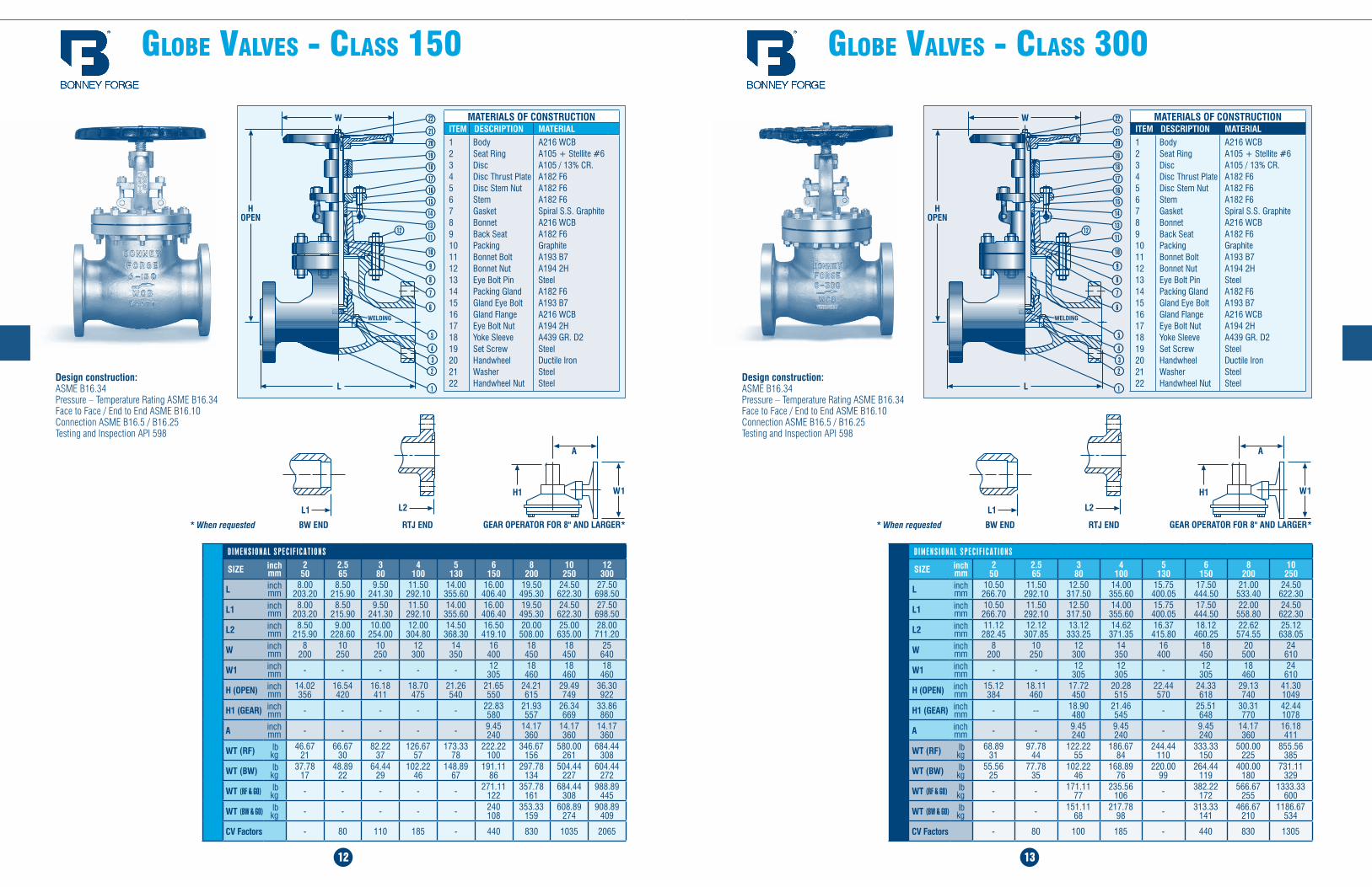
glObe ValVes - Class 150
12
glObe ValVes - Class 300
13
Design construction:ASME B16.34 Pressure – Temperature Rating ASME B16.34 Face to Face / End to End ASME B16.10 Connection ASME B16.5 / B16.25Testing and Inspection API 598
MATERIALS OF CONSTRUCTIONITEM DESCRIPTION MATERIAL12345678910111213141516171819202122
Body Seat Ring Disc Disc Thrust Plate Disc Stem Nut Stem Gasket Bonnet Back Seat Packing Bonnet Bolt Bonnet Nut Eye Bolt Pin Packing Gland Gland Eye Bolt Gland Flange Eye Bolt Nut Yoke Sleeve Set Screw Handwheel Washer Handwheel Nut
A216 WCB A105 + Stellite #6 A105 / 13% CR. A182 F6 A182 F6 A182 F6 Spiral S.S. Graphite A216 WCB A182 F6 Graphite A193 B7 A194 2H Steel A182 F6 A193 B7 A216 WCB A194 2H A439 GR. D2 Steel Ductile Iron Steel Steel
D I M E N S I O N A L S P E C I F I C A T I O N S
SIZE inch mm
2 50
2.5 65
3 80
4 100
5 130
6 150
8 200
10 250
L inch mm
10.50 266.70
11.50 292.10
12.50 317.50
14.00 355.60
15.75 400.05
17.50 444.50
21.00 533.40
24.50 622.30
L1 inch mm
10.50 266.70
11.50 292.10
12.50 317.50
14.00 355.60
15.75 400.05
17.50 444.50
22.00 558.80
24.50 622.30
L2 inch mm
11.12 282.45
12.12 307.85
13.12 333.25
14.62 371.35
16.37 415.80
18.12 460.25
22.62 574.55
25.12 638.05
W inch mm
8 200
10 250
12 300
14 350
16 400
18 450
20 500
24 610
W1 inch mm - - 12
30512
305 - 12 305
18 460
24 610
H (OPEN) inch mm
15.12 384
18.11 460
17.72 450
20.28 515
22.44 570
24.33 618
29.13 740
41.30 1049
H1 (GEAR) inch mm - -- 18.90
48021.46 545 - 25.51
64830.31 770
42.44 1078
A inch mm - - 9.45
2409.45 240 - 9.45
24014.17 360
16.18 411
WT (RF) lb kg
68.89 31
97.78 44
122.22 55
186.67 84
244.44 110
333.33 150
500.00 225
855.56 385
WT (BW) lb kg
55.56 25
77.78 35
102.22 46
168.89 76
220.00 99
264.44 119
400.00 180
731.11 329
WT (RF & GO) lb kg - - 171.11
77235.56
106 - 382.22 172
566.67 255
1333.33 600
WT (BW & GO) lb kg - - 151.11
68217.78
98 - 313.33 141
466.67 210
1186.67 534
CV Factors - 80 100 185 - 440 830 1305
Design construction:ASME B16.34 Pressure – Temperature Rating ASME B16.34 Face to Face / End to End ASME B16.10 Connection ASME B16.5 / B16.25Testing and Inspection API 598
MATERIALS OF CONSTRUCTIONITEM DESCRIPTION MATERIAL12345678910111213141516171819202122
Body Seat Ring Disc Disc Thrust Plate Disc Stem Nut Stem Gasket Bonnet Back Seat Packing Bonnet Bolt Bonnet Nut Eye Bolt Pin Packing Gland Gland Eye Bolt Gland Flange Eye Bolt Nut Yoke Sleeve Set Screw Handwheel Washer Handwheel Nut
A216 WCB A105 + Stellite #6 A105 / 13% CR. A182 F6 A182 F6 A182 F6 Spiral S.S. Graphite A216 WCB A182 F6 Graphite A193 B7 A194 2H Steel A182 F6 A193 B7 A216 WCB A194 2H A439 GR. D2 Steel Ductile Iron Steel Steel
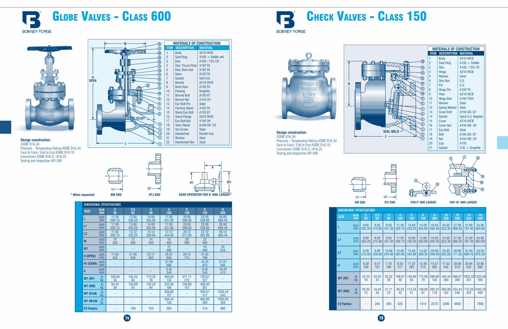
glObe ValVes - Class 600
14
CHeCk ValVes - Class 150
15
D I M E N S I O N A L S P E C I F I C A T I O N S
SIZE inch mm
2 50
2.5 65
3 80
4 100
5 130
6 150
8 200
L inch mm
11.50 292.10
13.00 330.20
14.00 355.60
17.00 431.80
20.00 508.00
22.00 558.80
26.00 660.40
L1 inch mm
11.50 292.10
13.00 330.20
14.00 355.60
17.00 431.80
20.00 508.00
22.00 558.80
26.00 660.40
L2 inch mm
11.62 295.15
13.12 333.25
14.12 358.65
17.12 434.85
20.12 511.05
22.12 561.85
26.12 663.45
W inch mm
10 250
12 300
14 350
16 400
20 500
22 560 -
W1 inch mm - - - 12
305 - 18 460
24 610
H (OPEN) inch mm
17.83 453
21.50 546
22.17 563
25.91 658
28.15 715
31.02 788 -
H1 (GEAR) inch mm - - - 27.09
688 - 34.25 870
37.01 940
A inch mm - - - 9.45
240 - 9.45 240
16.26 413
WT (RF) lb kg
100.00 45
142.22 64
173.33 78
300.00 135
471.11 212
726.67 327 -
WT (BW) lb kg
84.44 38
120.00 54
142.22 64
235.56 106
348.89 157
580.00 261 -
WT (RF & GO) lb kg - - - 348.89
157 - 926.67 417
1204.44 542
WT (BW & GO) lb kg - - - 284.44
128 - 800.00 360
1020.00 459
CV Factors - 100 153 263 - 513 882
Design construction:ASME B16.34 Pressure – Temperature Rating ASME B16.34 Face to Face / End to End ASME B16.10 Connection ASME B16.5 / B16.25Testing and Inspection API 598
MATERIALS OF CONSTRUCTIONITEM DESCRIPTION MATERIAL123456789101112131415161718192021
Body Seat Ring Disc Hinge Washer Disc Nut Pin Hinge Pin Yoke Hinge Bolt Washer Spring Washer Cover Bolt Gasket Cover Cover Nut Eye Bolt Bolt Nut Cap Gasket
A216 WCB A105 + Stellite A105 / 13% CR. A216 WCB Steel S.S. S.S. A182 F6 A216 WCB A182 F304 Steel Steel A193 GR. B7 Spiral S.S. Graphite A216 WCB A194 GR. 2H Steel A193 GR. B7 A194 GR. 2H A105 S.W. + Graphite
D I M E N S I O N A L S P E C I F I C A T I O N S
SIZE inch mm
2 50
2.5 65
3 80
4 100
5 130
6 150
8 200
10 250
12 300
14 350
16 400
L inch mm
8.00 203.20
8.50 215.90
9.50 241.30
11.50 292.10
13.00 330.20
14.00 355.60
19.50 495.30
24.50 622.30
27.50 698.50
31.00 787.40
34.00 863.60
L1 inch mm
8.00 203.20
8.50 215.90
9.50 241.30
11.50 292.10
13.00 330.20
14.00 355.60
19.50 495.30
24.50 622.30
27.50 698.50
31.00 787.40
34.00 863.60
L2 inch mm
8.50 215.90
9.00 228.60
10.00 254.00
12.00 304.80
13.50 342.90
14.50 368.30
20.00 508.00
25.00 635.00
28.00 711.20
31.50 800.10
34.50 876.30
H inch mm
6.30 160
6.57 167
7.10 180
8.54 217
11.22 285
12.40 315
14.37 365
17.52 445
20.08 510
20.94 532
22.95 583
WT (RF) lb kg
42.22 19
53.33 24
62.22 28
106.67 48
140.00 63
175.56 79
288.89 130
444.44 200
666.67 300
1002.22 451
1235.56 556
WT (BW) lb kg
33.33 15
44.44 20
51.11 23
93.33 42
113.33 51
148.89 67
262.22 118
360.00 162
524.44 236
715.56 322
1042.22 469
CV Factors - 246 356 620 - 1414 2370 3300 4000 - 7900
Design construction:ASME B16.34 Pressure – Temperature Rating ASME B16.34 Face to Face / End to End ASME B16.10 Connection ASME B16.5 / B16.25Testing and Inspection API 598
MATERIALS OF CONSTRUCTIONITEM DESCRIPTION MATERIAL12345678910111213141516171819202122
Body Seat Ring Disc Disc Thrust Plate Disc Stem Nut Stem Gasket Bonnet Back Seat Packing Bonnet Bolt Bonnet Nut Eye Bolt Pin Packing Gland Gland Eye Bolt Gland Flange Eye Bolt Nut Yoke Sleeve Set Screw Handwheel Washer Handwheel Nut
A216 WCB A105 + Stellite #6 A105 / 13% CR. A182 F6 A182 F6 A182 F6 Soft Iron A216 WCB A182 F6 Graphite A193 B7 A194 2H Steel A182 F6 A193 B7 A216 WCB A194 2H A439 GR. D2 Steel Ductile Iron Steel Steel
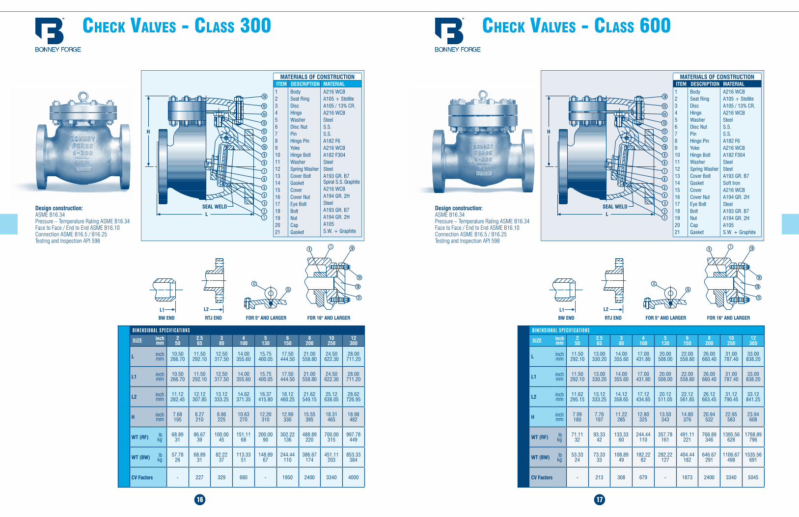
CHeCk ValVes - Class 300
16
CHeCk ValVes - Class 600
17
Design construction:ASME B16.34 Pressure – Temperature Rating ASME B16.34 Face to Face / End to End ASME B16.10 Connection ASME B16.5 / B16.25Testing and Inspection API 598
D I M E N S I O N A L S P E C I F I C A T I O N S
SIZE inch mm
2 50
2.5 65
3 80
4 100
5 130
6 150
8 200
10 250
12 300
L inch mm
11.50 292.10
13.00 330.20
14.00 355.60
17.00 431.80
20.00 508.00
22.00 558.80
26.00 660.40
31.00 787.40
33.00 838.20
L1 inch mm
11.50 292.10
13.00 330.20
14.00 355.60
17.00 431.80
20.00 508.00
22.00 558.80
26.00 660.40
31.00 787.40
33.00 838.20
L2 inch mm
11.62 295.15
13.12 333.25
14.12 358.65
17.12 434.85
20.12 511.05
22.12 561.85
26.12 663.45
31.12 790.45
33.12 841.25
H inch mm
7.09 180
7.76 197
11.22 285
12.80 325
13.50 343
14.80 376
20.94 532
22.95 583
23.94 608
WT (RF) lb kg
71.11 32
93.33 42
133.33 60
244.44 110
357.78 161
491.11 221
768.89 346
1395.56 628
1768.89 796
WT (BW) lb kg
53.33 24
73.33 33
108.89 49
182.22 82
282.22 127
404.44 182
646.67 291
1106.67 498
1535.56 691
CV Factors - 213 308 679 - 1873 2400 3340 5045
Design construction:ASME B16.34 Pressure – Temperature Rating ASME B16.34 Face to Face / End to End ASME B16.10 Connection ASME B16.5 / B16.25Testing and Inspection API 598
D I M E N S I O N A L S P E C I F I C A T I O N S
SIZE inch mm
2 50
2.5 65
3 80
4 100
5 130
6 150
8 200
10 250
12 300
L inch mm
10.50 266.70
11.50 292.10
12.50 317.50
14.00 355.60
15.75 400.05
17.50 444.50
21.00 558.80
24.50 622.30
28.00 711.20
L1 inch mm
10.50 266.70
11.50 292.10
12.50 317.50
14.00 355.60
15.75 400.05
17.50 444.50
21.00 558.80
24.50 622.30
28.00 711.20
L2 inch mm
11.12 282.45
12.12 307.85
13.12 333.25
14.62 371.35
16.37 415.80
18.12 460.25
21.62 549.15
25.12 638.05
28.62 726.95
H inch mm
7.68 195
8.27 210
8.86 225
10.63 270
12.20 310
12.99 330
15.55 395
18.31 465
18.98 482
WT (RF) lb kg
68.89 31
86.67 39
100.00 45
151.11 68
200.00 90
302.22 136
488.89 220
700.00 315
997.78 449
WT (BW) lb kg
57.78 26
68.89 31
82.22 37
113.33 51
148.89 67
244.44 110
386.67 174
451.11 203
853.33 384
CV Factors - 227 329 680 - 1950 2400 3340 4000
MATERIALS OF CONSTRUCTIONITEM DESCRIPTION MATERIAL123456789101112131415161718192021
Body Seat Ring Disc Hinge Washer Disc Nut Pin Hinge Pin Yoke Hinge Bolt Washer Spring Washer Cover Bolt Gasket Cover Cover Nut Eye Bolt Bolt Nut Cap Gasket
A216 WCB A105 + Stellite A105 / 13% CR. A216 WCB Steel S.S. S.S. A182 F6 A216 WCB A182 F304 Steel Steel A193 GR. B7 Spiral S.S. Graphite A216 WCB A194 GR. 2H Steel A193 GR. B7 A194 GR. 2H A105 S.W. + Graphite
MATERIALS OF CONSTRUCTIONITEM DESCRIPTION MATERIAL123456789101112131415161718192021
Body Seat Ring Disc Hinge Washer Disc Nut Pin Hinge Pin Yoke Hinge Bolt Washer Spring Washer Cover Bolt Gasket Cover Cover Nut Eye Bolt Bolt Nut Cap Gasket
A216 WCB A105 + Stellite A105 / 13% CR. A216 WCB Steel S.S. S.S. A182 F6 A216 WCB A182 F304 Steel Steel A193 GR. B7 Soft Iron A216 WCB A194 GR. 2H Steel A193 GR. B7 A194 GR. 2H A105 S.W. + Graphite
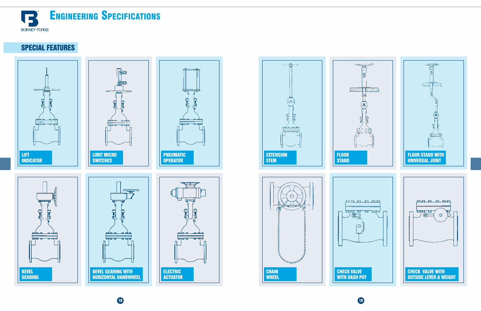
engineering speCifiCaTiOns
18 19
LIFT INDICATOR
BEVEL GEARING
LIMIT MICRO SWITCHES
PNEUMATIC OPERATOR
BEVEL GEARING WITH HORIZONTAL HANDWHEEL
ELECTRIC ACTUATOR
SPECIAL FEATURES
EXTENSION STEM
CHAIN WHEEL
FLOOR STAND
FLOOR STAND WITH UNIVERSAL JOINT
CHECK VALVE WITH DASH POT
CHECK VALVE WITH OUTSIDE LEVER & WEIGHT
20 21
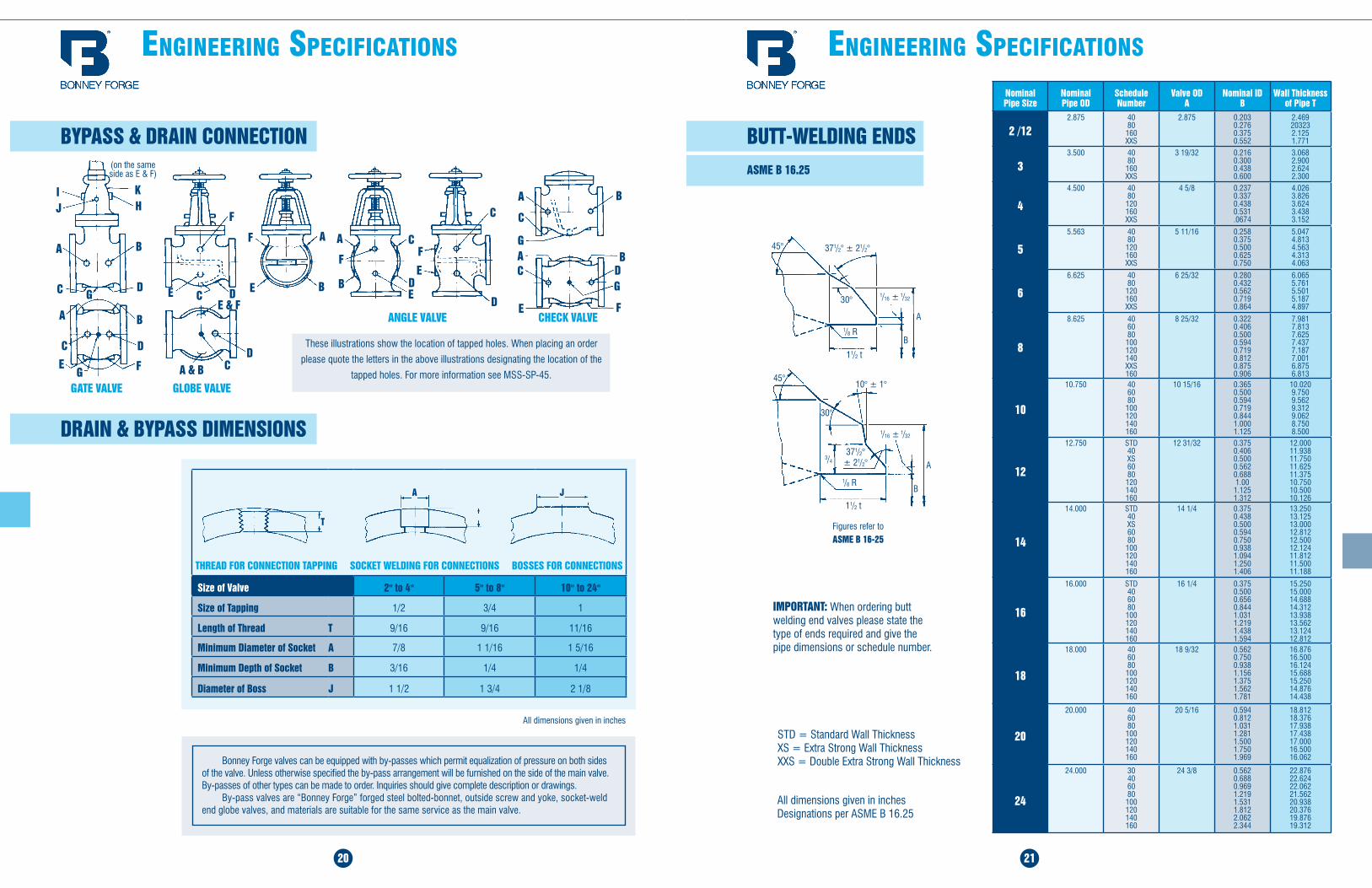
BYPASS & DRAIN CONNECTION
engineering speCifiCaTiOns engineering speCifiCaTiOns
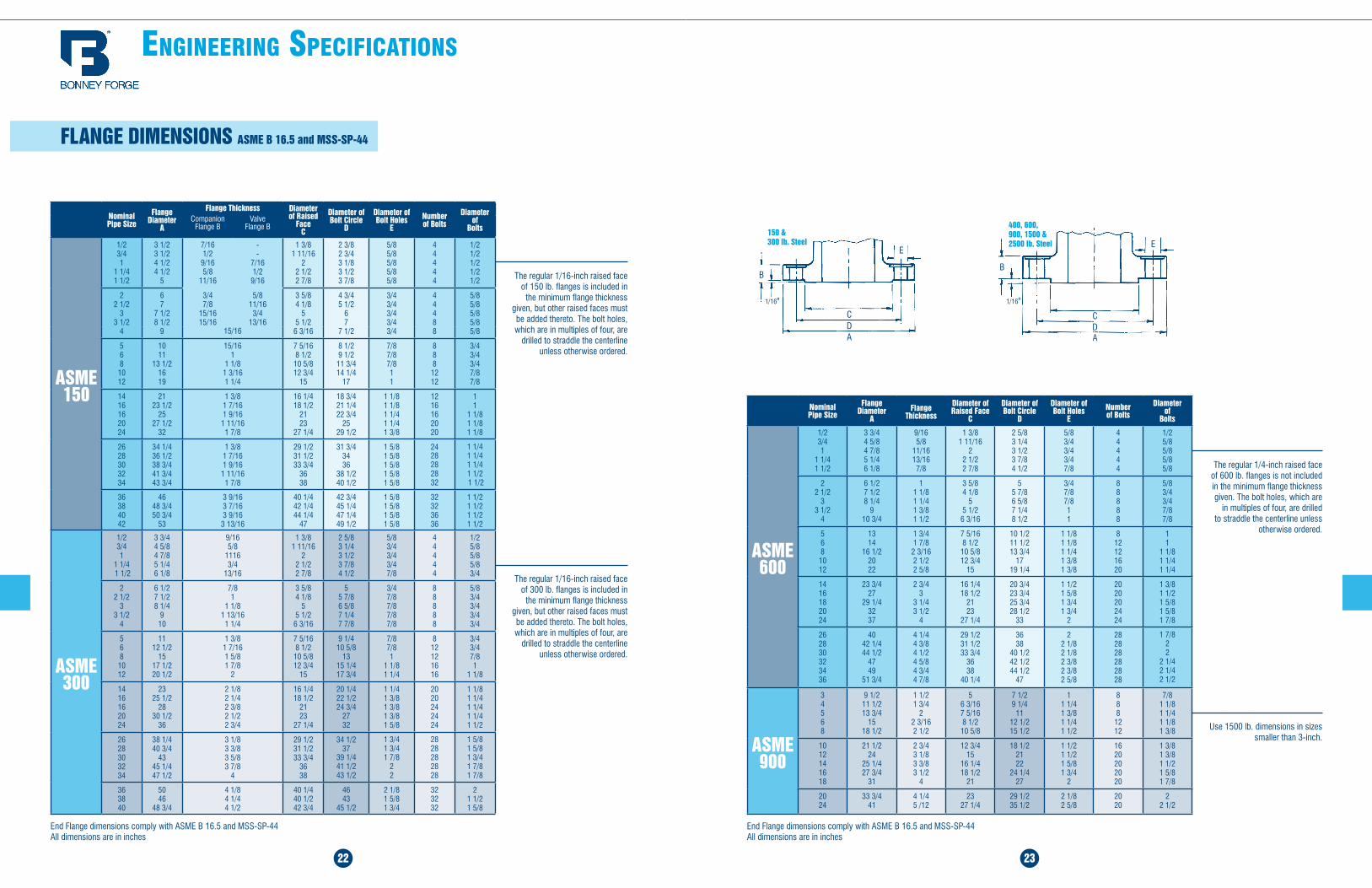
BUTT-WELDING ENDS ASME B 16.25
Bonney Forge valves can be equipped with by-passes which permit equalization of pressure on both sides of the valve. Unless otherwise specified the by-pass arrangement will be furnished on the side of the main valve. By-passes of other types can be made to order. Inquiries should give complete description or drawings.
By-pass valves are “Bonney Forge” forged steel bolted-bonnet, outside screw and yoke, socket-weld end globe valves, and materials are suitable for the same service as the main valve.
All dimensions given in inches
I K
J H
A B
C D
(on the same side as E & F)
C
A B
D
EG F
GATE VALVE GLOBE VALVE
CD
A & B
E & FE
F
DC
ANGLE VALVE
These illustrations show the location of tapped holes. When placing an order
please quote the letters in the above illustrations designating the location of the
tapped holes. For more information see MSS-SP-45.
AF
E B
A
B
C
DE
FF
E
C
DG
DRAIN & BYPASS DIMENSIONS
CHECK VALVE
A B
C
GAC
B
E F
DG
THREAD FOR CONNECTION TAPPING SOCKET WELDING FOR CONNECTIONS BOSSES FOR CONNECTIONS
Size of Valve .5 2" to 4" 5" to 8" 10" to 24"
Size of Tapping 1/2 3/4 1
Length of Thread T 9/16 9/16 11/16
Minimum Diameter of Socket A 7/8 1 1/16 1 5/16
Minimum Depth of Socket B 3/16 1/4 1/4
Diameter of Boss J 1 1/2 1 3/4 2 1/8
A J
T
A
B
11/2 t
1/8 R
3/4
371/2° ± 21/2°
1/16 ± 1/32
10° ± 1°
30°
45°
11/2 t
1/8 R
A
B
1/16 ± 1/3230°
45° 371/2° ± 21/2°
All dimensions given in inches Designations per ASME B 16.25
STD = Standard Wall Thickness XS = Extra Strong Wall Thickness XXS = Double Extra Strong Wall Thickness
IMPORTANT: When ordering butt welding end valves please state the type of ends required and give the pipe dimensions or schedule number.
Figures refer to ASME B 16-25
Nominal Pipe Size
Nominal Pipe OD
Schedule Number
Valve OD A
Nominal ID B
Wall Thickness of Pipe T
2 /122.875 40
80 160 XXS
2.875 0.203 0.276 0.375 0.552
2.469 20323 2.125 1.771
33.500 40
80 160 XXS
3 19/32 0.216 0.300 0.438 0.600
3.068 2.900 2.624 2.300
4
4.500 40 80 120 160 XXS
4 5/8 0.237 0.337 0.438 0.531 .0674
4.026 3.826 3.624 3.438 3.152
5
5.563 40 80 120 160 XXS
5 11/16 0.258 0.375 0.500 0.625 0.750
5.047 4.813 4.563 4.313 4.063
6
6.625 40 80 120 160 XXS
6 25/32 0.280 0.432 0.562 0.719 0.864
6.065 5.761 5.501 5.187 4.897
8
8.625 40 60 80 100 120 140 XXS 160
8 25/32 0.322 0.406 0.500 0.594 0.719 0.812 0.875 0.906
7.981 7.813 7.625 7.437 7.187 7.001 6.875 6.813
10
10.750 40 60 80 100 120 140 160
10 15/16 0.365 0.500 0.594 0.719 0.844 1.000 1.125
10.020 9.750 9.562 9.312 9.062 8.750 8.500
12
12.750 STD 40 XS 60 80 120 140 160
12 31/32 0.375 0.406 0.500 0.562 0.688 1.00
1.125 1.312
12.000 11.938 11.750 11.625 11.375 10.750 10.500 10.126
14
14.000 STD 40 XS 60 80 100 120 140 160
14 1/4 0.375 0.438 0.500 0.594 0.750 0.938 1.094 1.250 1.406
13.250 13.125 13.000 12.812 12.500 12.124 11.812 11.500 11.188
16
16.000 STD 40 60 80 100 120 140 160
16 1/4 0.375 0.500 0.656 0.844 1.031 1.219 1.438 1.594
15.250 15.000 14.688 14.312 13.938 13.562 13.124 12.812
18
18.000 40 60 80 100 120 140 160
18 9/32 0.562 0.750 0.938 1.156 1.375 1.562 1.781
16.876 16.500 16.124 15.688 15.250 14.876 14.438
20
20.000 40 60 80 100 120 140 160
20 5/16 0.594 0.812 1.031 1.281 1.500 1.750 1.969
18.812 18.376 17.938 17.438 17.000 16.500 16.062
24
24.000 30 40 60 80 100 120 140 160
24 3/8 0.562 0.688 0.969 1.219 1.531 1.812 2.062 2.344
22.876 22.624 22.062 21.562 20.938 20.376 19.876 19.312
22 23
engineering speCifiCaTiOns
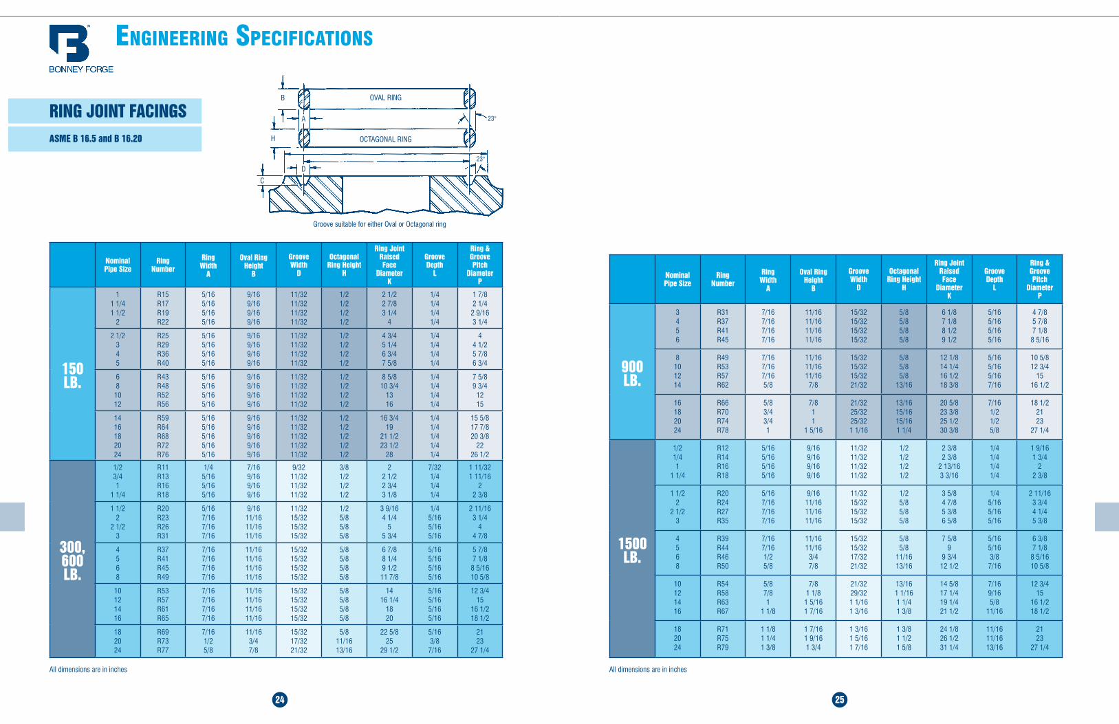
FLANGE DIMENSIONS ASME B 16.5 and MSS-SP-44
Nominal Pipe Size
Flange Diameter
A
Flange Thickness Diameter of Raised
Face C
Diameter of Bolt Circle
D
Diameter of Bolt Holes
ENumber of Bolts
Diameter of
BoltsCompanion
Flange BValve
Flange B
ASME 150
1/2 3/4 1
1 1/4 1 1/2
3 1/2 3 1/2 4 1/2 4 1/2
5
7/16 1/2 9/16 5/8
11/16
- -
7/16 1/2 9/16
1 3/8 1 11/16
2 2 1/2 2 7/8
2 3/8 2 3/4 3 1/8 3 1/2 3 7/8
5/8 5/8 5/8 5/8 5/8
4 4 4 4 4
1/2 1/2 1/2 1/2 1/2
2 2 1/2
3 3 1/2
4
6 7
7 1/2 8 1/2
9
3/4 7/8
15/16 15/16
5/8 11/16 3/4
13/16
3 5/8 4 1/8
5 5 1/2
6 3/16
4 3/4 5 1/2
6 7
7 1/2
3/4 3/4 3/4 3/4 3/4
4 4 4 8 8
5/8 5/8 5/8 5/8 5/815/16
5 6 8 10 12
10 11
13 1/2 16 19
15/16 1
1 1/8 1 3/16 1 1/4
7 5/16 8 1/2
10 5/8 12 3/4
15
8 1/2 9 1/2
11 3/4 14 1/4
17
7/8 7/8 7/8 1 1
8 8 8
12 12
3/4 3/4 3/4 7/8 7/8
14 16 16 20 24
21 23 1/2
25 27 1/2
32
1 3/8 1 7/16 1 9/16 1 11/16
1 7/8
16 1/4 18 1/2
21 23
27 1/4
18 3/4 21 1/4 22 3/4
25 29 1/2
1 1/8 1 1/8 1 1/4 1 1/4 1 3/8
12 16 16 20 20
1 1
1 1/8 1 1/8 1 1/8
26 28 30 32 34
34 1/4 36 1/2 38 3/4 41 3/4 43 3/4
1 3/8 1 7/16 1 9/16 1 11/16
1 7/8
29 1/2 31 1/2 33 3/4
36 38
31 3/4 34 36
38 1/2 40 1/2
1 5/8 1 5/8 1 5/8 1 5/8 1 5/8
24 28 28 28 32
1 1/4 1 1/4 1 1/4 1 1/2 1 1/2
36 38 40 42
46 48 3/4 50 3/4
53
3 9/16 3 7/16 3 9/16 3 13/16
40 1/4 42 1/4 44 1/4
47
42 3/4 45 1/4 47 1/4 49 1/2
1 5/8 1 5/8 1 5/8 1 5/8
32 3236 36
1 1/2 1 1/2 1 1/2 1 1/2
ASME 300
1/2 3/4 1
1 1/4 1 1/2
3 3/4 4 5/8 4 7/8 5 1/4 6 1/8
9/16 5/8
1116 3/4
13/16
1 3/8 1 11/16
2 2 1/2 2 7/8
2 5/8 3 1/4 3 1/2 3 7/8 4 1/2
5/8 3/4 3/4 3/4 7/8
4 4 4 4 4
1/2 5/8 5/8 5/8 3/4
2 2 1/2
3 3 1/2
4
6 1/2 7 1/2 8 1/4
9 10
7/8 1
1 1/8 1 13/16 1 1/4
3 5/8 4 1/8
5 5 1/2
6 3/16
5 5 7/8 6 5/8 7 1/4 7 7/8
3/4 7/8 7/8 7/8 7/8
8 8 8 8 8
5/8 3/4 3/4 3/4 3/4
5 6 8 10 12
11 12 1/2
15 17 1/2 20 1/2
1 3/8 1 7/16 1 5/8 1 7/8
2
7 5/16 8 1/2
10 5/8 12 3/4
15
9 1/4 10 5/8
13 15 1/4 17 3/4
7/8 7/8 1
1 1/8 1 1/4
8 12 12 16 16
3/4 3/4 7/8 1
1 1/8
14 1616 20 24
23 25 1/2
28 30 1/2
36
2 1/8 2 1/4 2 3/8 2 1/2 2 3/4
16 1/4 18 1/2
21 23
27 1/4
20 1/4 22 1/2 24 3/4
27 32
1 1/4 1 3/8 1 3/8 1 3/8 1 5/8
20 20 24 24 24
1 1/8 1 1/4 1 1/4 1 1/4 1 1/2
26 28 30 32 34
38 1/4 40 3/4
43 45 1/4 47 1/2
3 1/8 3 3/8 3 5/8 3 7/8
4
29 1/2 31 1/2 33 3/4
36 38
34 1/2 37
39 1/4 41 1/2 43 1/2
1 3/4 1 3/4 1 7/8
2 2
28 28 28 28 28
1 5/8 1 5/8 1 3/4 1 7/8 1 7/8
36 38 40
50 46
48 3/4
4 1/8 4 1/4 4 1/2
40 1/4 40 1/2 42 3/4
46 43
45 1/2
2 1/8 1 5/8 1 3/4
32 32 32
2 1 1/2 1 5/8
The regular 1/16-inch raised face of 150 lb. flanges is included in
the minimum flange thickness given, but other raised faces must be added thereto. The bolt holes, which are in multiples of four, are
drilled to straddle the centerline unless otherwise ordered.
The regular 1/16-inch raised face of 300 lb. flanges is included in
the minimum flange thickness given, but other raised faces must be added thereto. The bolt holes, which are in multiples of four, are
drilled to straddle the centerline unless otherwise ordered.
End Flange dimensions comply with ASME B 16.5 and MSS-SP-44All dimensions are in inches
Nominal Pipe Size
Flange Diameter
AFlange
Thickness
Diameter of Raised Face
C
Diameter of Bolt Circle
D
Diameter of Bolt Holes
ENumber of Bolts
Diameter of
Bolts
ASME 600
1/2 3/4 1
1 1/4 1 1/2
3 3/4 4 5/8 4 7/8 5 1/4 6 1/8
9/16 5/8
11/16 13/16
7/8
1 3/8 1 11/16
2 2 1/2 2 7/8
2 5/8 3 1/4 3 1/2 3 7/8 4 1/2
5/8 3/4 3/4 3/4 7/8
4 4 4 4 4
1/2 5/8 5/8 5/8 5/8
2 2 1/2
3 3 1/2
4
6 1/2 7 1/2 8 1/4
9 10 3/4
1 1 1/8 1 1/4 1 3/8 1 1/2
3 5/8 4 1/8
5 5 1/2 6 3/16
5 5 7/8 6 5/8 7 1/4 8 1/2
3/4 7/8 7/8 1 1
8 8 8 8 8
5/8 3/4 3/4 7/8 7/8
5 6 8 10 12
13 14
16 1/2 20 22
1 3/4 1 7/8 2 3/16 2 1/2 2 5/8
7 5/16 8 1/2 10 5/8 12 3/4
15
10 1/2 11 1/2 13 3/4
17 19 1/4
1 1/8 1 1/8 1 1/4 1 3/8 1 3/8
8 12 12 16 20
1 1
1 1/8 1 1/4 1 1/4
14 16 18 20 24
23 3/4 27
29 1/4 32 37
2 3/4 3
3 1/4 3 1/2
4
16 1/4 18 1/2
21 23
27 1/4
20 3/4 23 3/4 25 3/4 28 1/2
33
1 1/2 1 5/8 1 3/4 1 3/4
2
20 20 20 24 24
1 3/8 1 1/2 1 5/8 1 5/8 1 7/8
26 28 30 32 34 36
40 42 1/4 44 1/2
47 49
51 3/4
4 1/4 4 3/8 4 1/2 4 5/8 4 3/4 4 7/8
29 1/2 31 1/2 33 3/4
36 38
40 1/4
36 38
40 1/2 42 1/2 44 1/2
47
2 2 1/8 2 1/8 2 3/8 2 3/8 2 5/8
28 28 28 28 28 28
1 7/8 2 2
2 1/4 2 1/4 2 1/2
ASME 900
3 4 5 6 8
9 1/2 11 1/2 13 3/4
15 18 1/2
1 1/2 1 3/4
2 2 3/16 2 1/2
5 6 3/16 7 5/16 8 1/2 10 5/8
7 1/2 9 1/4
11 12 1/2 15 1/2
1 1 1/4 1 3/8 1 1/4 1 1/2
8 8 8 12 12
7/8 1 1/8 1 1/4 1 1/8 1 3/8
10 12 14 16 18
21 1/2 24
25 1/4 27 3/4
31
2 3/4 3 1/8 3 3/8 3 1/2
4
12 3/4 15
16 1/4 18 1/2
21
18 1/2 21 22
24 1/4 27
1 1/2 1 1/2 1 5/8 1 3/4
2
16 20 20 20 20
1 3/8 1 3/8 1 1/2 1 5/8 1 7/8
20 24
33 3/4 41
4 1/4 5 /12
23 27 1/4
29 1/2 35 1/2
2 1/8 2 5/8
20 20
2 2 1/2
150 & 300 lb. Steel
ADC
B
1/16"
E
A
CD
1/16"
B
E
400, 600, 900, 1500 & 2500 lb. Steel
Use 1500 lb. dimensions in sizes smaller than 3-inch.
The regular 1/4-inch raised face of 600 lb. flanges is not included in the minimum flange thickness given. The bolt holes, which are
in multiples of four, are drilled to straddle the centerline unless
otherwise ordered.
End Flange dimensions comply with ASME B 16.5 and MSS-SP-44All dimensions are in inches
24 25
engineering speCifiCaTiOns
RING JOINT FACINGS ASME B 16.5 and B 16.20
Nominal Pipe Size
Ring Number
Ring Width
A
Oval Ring Height
B
Groove Width
D
Octagonal Ring Height
H
Ring Joint Raised Face
Diameter K
Groove Depth
L
Ring & Groove Pitch
Diameter P
150 LB.
1 1 1/4 1 1/2
2
R15 R17 R19 R22
5/16 5/16 5/16 5/16
9/16 9/16 9/16 9/16
11/32 11/32 11/32 11/32
1/2 1/2 1/2 1/2
2 1/2 2 7/8 3 1/4
4
1/4 1/4 1/4 1/4
1 7/8 2 1/4
2 9/16 3 1/4
2 1/2 3 4 5
R25 R29 R36 R40
5/16 5/16 5/16 5/16
9/16 9/16 9/16 9/16
11/32 11/32 11/32 11/32
1/2 1/2 1/2 1/2
4 3/4 5 1/4 6 3/4 7 5/8
1/4 1/4 1/4 1/4
4 4 1/2 5 7/8 6 3/4
6 8 10 12
R43 R48 R52 R56
5/16 5/16 5/16 5/16
9/16 9/16 9/16 9/16
11/32 11/32 11/32 11/32
1/2 1/2 1/2 1/2
8 5/8 10 3/4
13 16
1/4 1/4 1/4 1/4
7 5/8 9 3/4
12 15
14 16 18 20 24
R59 R64 R68 R72 R76
5/16 5/16 5/16 5/16 5/16
9/16 9/16 9/16 9/16 9/16
11/32 11/32 11/32 11/32 11/32
1/2 1/2 1/2 1/2 1/2
16 3/4 19
21 1/2 23 1/2
28
1/4 1/4 1/4 1/4 1/4
15 5/8 17 7/8 20 3/8
22 26 1/2
300, 600 LB.
1/2 3/4 1
1 1/4
R11 R13 R16 R18
1/4 5/16 5/16 5/16
7/16 9/16 9/16 9/16
9/32 11/32 11/32 11/32
3/8 1/2 1/2 1/2
2 2 1/2 2 3/4 3 1/8
7/32 1/4 1/4 1/4
1 11/32 1 11/16
2 2 3/8
1 1/2 2
2 1/2 3
R20 R23 R26 R31
5/16 7/16 7/16 7/16
9/16 11/16 11/16 11/16
11/32 15/32 15/32 15/32
1/2 5/8 5/8 5/8
3 9/16 4 1/4
5 5 3/4
1/4 5/16 5/16 5/16
2 11/16 3 1/4
4 4 7/8
4 5 6 8
R37 R41 R45 R49
7/16 7/16 7/16 7/16
11/16 11/16 11/16 11/16
15/32 15/32 15/32 15/32
5/8 5/8 5/8 5/8
6 7/8 8 1/4 9 1/2
11 7/8
5/16 5/16 5/16 5/16
5 7/8 7 1/8
8 5/16 10 5/8
10 12 14 16
R53 R57 R61 R65
7/16 7/16 7/16 7/16
11/16 11/16 11/16 11/16
15/32 15/32 15/32 15/32
5/8 5/8 5/8 5/8
14 16 1/4
18 20
5/16 5/16 5/16 5/16
12 3/4 15
16 1/2 18 1/2
18 20 24
R69 R73 R77
7/16 1/2 5/8
11/16 3/4 7/8
15/32 17/32 21/32
5/8 11/16 13/16
22 5/8 25
29 1/2
5/16 3/8
7/16
21 23
27 1/4
All dimensions are in inches
B
C
H
A 23°
Groove suitable for either Oval or Octagonal ring
OCTAGONAL RING
OVAL RING
23°
Nominal Pipe Size
Ring Number
Ring Width
A
Oval Ring Height
B
Groove Width
D
Octagonal Ring Height
H
Ring Joint Raised Face
Diameter K
Groove Depth
L
Ring & Groove Pitch
Diameter P
900 LB.
3 4 5 6
R31 R37 R41 R45
7/16 7/16 7/16 7/16
11/16 11/16 11/16 11/16
15/32 15/32 15/32 15/32
5/8 5/8 5/8 5/8
6 1/8 7 1/8 8 1/2 9 1/2
5/16 5/16 5/16 5/16
4 7/8 5 7/8 7 1/8 8 5/16
8 10 12 14
R49 R53 R57 R62
7/16 7/16 7/16 5/8
11/16 11/16 11/16
7/8
15/32 15/32 15/32 21/32
5/8 5/8 5/8
13/16
12 1/8 14 1/4 16 1/2 18 3/8
5/16 5/16 5/16 7/16
10 5/8 12 3/4
15 16 1/2
16 18 20 24
R66 R70 R74 R78
5/8 3/4 3/4 1
7/8 1 1
1 5/16
21/32 25/32 25/32 1 1/16
13/16 15/16 15/16 1 1/4
20 5/8 23 3/8 25 1/2 30 3/8
7/16 1/2 1/2 5/8
18 1/2 21 23
27 1/4
1500 LB.
1/2 1/4 1
1 1/4
R12 R14 R16 R18
5/16 5/16 5/16 5/16
9/16 9/16 9/16 9/16
11/32 11/32 11/32 11/32
1/2 1/2 1/2 1/2
2 3/8 2 3/8
2 13/16 3 3/16
1/4 1/4 1/4 1/4
1 9/16 1 3/4
2 2 3/8
1 1/2 2
2 1/2 3
R20 R24 R27 R35
5/16 7/16 7/16 7/16
9/16 11/16 11/16 11/16
11/32 15/32 15/32 15/32
1/2 5/8 5/8 5/8
3 5/8 4 7/8 5 3/8 6 5/8
1/4 5/16 5/16 5/16
2 11/16 3 3/4 4 1/4 5 3/8
4 5 6 8
R39 R44 R46 R50
7/16 7/16 1/2 5/8
11/16 11/16
3/4 7/8
15/32 15/32 17/32 21/32
5/8 5/8
11/16 13/16
7 5/8 9
9 3/4 12 1/2
5/16 5/16 3/8 7/16
6 3/8 7 1/8 8 5/16 10 5/8
10 12 14 16
R54 R58 R63 R67
5/8 7/8 1
1 1/8
7/8 1 1/8
1 5/16 1 7/16
21/32 29/32 1 1/16 1 3/16
13/16 1 1/16 1 1/4 1 3/8
14 5/8 17 1/4 19 1/4 21 1/2
7/16 9/16 5/8
11/16
12 3/4 15
16 1/2 18 1/2
18 20 24
R71 R75 R79
1 1/8 1 1/4 1 3/8
1 7/16 1 9/16 1 3/4
1 3/16 1 5/16 1 7/16
1 3/8 1 1/2 1 5/8
24 1/8 26 1/2 31 1/4
11/16 11/16 13/16
21 23
27 1/4
All dimensions are in inches
D
26 27
engineering speCifiCaTiOns
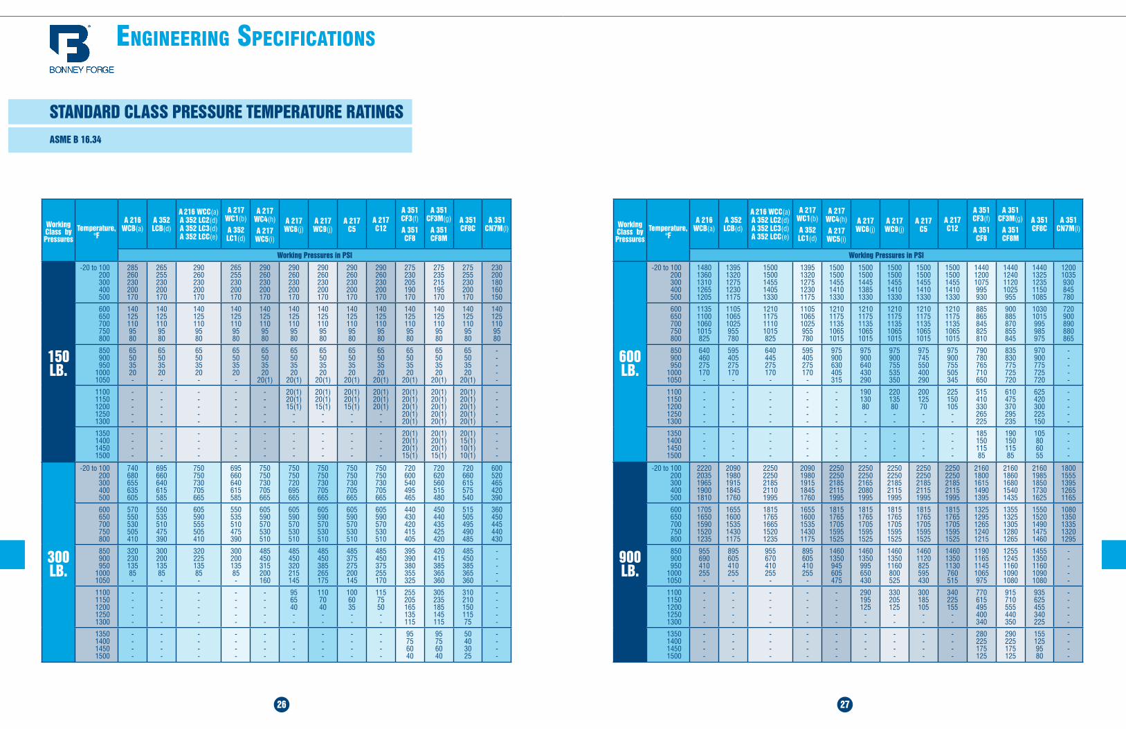
STANDARD CLASS PRESSURE TEMPERATURE RATINGS ASME B 16.34
Working Class by Pressures
Temperature, °F
A 216 WCB(a)
A 352 LCB(d)
A 216 WCC(a) A 352 LC2(d) A 352 LC3(d) A 352 LCC(e)
A 217 WC1(b)
A 352 LC1(d)
A 217 WC4(h)
A 217 WC5(i)
A 217 WC6(j)
A 217 WC9(j)
A 217 C5
A 217 C12
A 351 CF3(f)
A 351 CF8
A 351 CF3M(g)
A 351 CF8M
A 351 CF8C
A 351 CN7M(l)
Working Pressures in PSI
150 LB.
-20 to 100 200 300 400 500
285 260 230 200 170
265 255 230 200 170
290 260 230 200 170
265 255 230 200 170
290 260 230 200 170
290 260 230 200 170
290 260 230 200 170
290 260 230 200 170
290 260 230 200 170
275 230 205 190 170
275 235 215 195 170
275 255 230 200 170
230 200 180 160 150
600 650 700 750 800
140 125 110 95 80
140 125 110 95 80
140 125 110 95 80
140 125 110 95 80
140 125 110 95 80
140 125 110 95 80
140 125 110 95 80
140 125 110 95 80
140 125 110 95 80
140 125 110 95 80
140 125 110 95 80
140 125 110 95 80
140 125 110 95 80
850 900 950
1000 1050
65 50 35 20 -
65 50 35 20 -
65 50 35 20 -
65 50 35 20 -
65 50 35 20
20(1)
65 50 35 20
20(1)
65 50 35 20
20(1)
65 50 35 20
20(1)
65 50 35 20
20(1)
65 50 35 20
20(1)
65 50 35 20
20(1)
65 50 35 20
20(1)
- - - - -
1100 1150 1200 1250 1300
- - - - -
- - - - -
- - - - -
- - - - -
- - - - -
20(1) 20(1) 15(1)
- -
20(1) 20(1) 15(1)
- -
20(1) 20(1) 15(1)
- -
20(1) 20(1) 20(1)
- -
20(1) 20(1) 20(1) 20(1) 20(1)
20(1) 20(1) 20(1) 20(1) 20(1)
20(1) 20(1) 20(1) 20(1) 20(1)
- - - - -
1350 1400 1450 1500
- - - -
- - - -
- - - -
- - - -
- - - -
- - - -
- - - -
- - - -
- - - -
20(1) 20(1) 20(1) 15(1)
20(1) 20(1) 20(1) 15(1)
20(1) 15(1) 10(1) 10(1)
- - - -
Working Class by Pressures
Temperature, °F
A 216 WCB(a)
A 352 LCB(d)
A 216 WCC(a) A 352 LC2(d) A 352 LC3(d) A 352 LCC(e)
A 217 WC1(b)
A 352 LC1(d)
A 217 WC4(h)
A 217 WC5(i)
A 217 WC6(j)
A 217 WC9(j)
A 217 C5
A 217 C12
A 351 CF3(f)
A 351 CF8
A 351 CF3M(g)
A 351 CF8M
A 351 CF8C
A 351 CN7M(l)
Working Pressures in PSI
300 LB.
-20 to 100 200 300 400 500
740 680 655 635 605
695 660 640 615 585
750 750 730 705 665
695 660 640 615 585
750 750 730 705 665
750 750 720 695 665
750 750 730 705 665
750 750 730 705 665
750 750 730 705 665
720 600 540 495 465
720 620 560 515 480
720 660 615 575 540
600 520 465 420 390
600 650 700 750 800
570 550 530 505 410
550 535 510 475 390
605 590 555 505 410
550 535 510 475 390
605 590 570 530 510
605 590 570 530 510
605 590 570 530 510
605 590 570 530 510
605 590 570 530 510
440 430 420 415 405
450 440 435 425 420
515 505 495 490 485
360 450 445 440 430
850 900 950
1000 1050
320 230 135 85 -
300 200 135 85 -
320 225 135 85 -
300 200 135 85 -
485 450 315 200 160
485 450 320 215 145
485 450 385 265 175
485 375 275 200 145
485 450 375 255 170
395 390 380 355 325
420 415 385 365 360
485 450 385 365 360
- - - - -
1100 1150 1200 1250 1300
- - - - -
- - - --
- - - --
- - - - -
- - - - -
95 65 40 - -
110 70 40 - -
100 60 35 - -
115 75 50 - -
255 205 165 135 115
305 235 185 145 115
310 210 150 115 75
- - - - -
1350 1400 1450 1500
- - - -
- - --
- - - -
- - - -
- - - -
- - - -
- - - -
- - - -
- - - -
95 75 60 40
95 75 60 40
50 40 30 25
- -- -
600 LB.
-20 to 100 200 300 400 500
1480 1360 1310 1265 1205
1395 1320 1275 1230 1175
1500 1500 1455 1405 1330
1395 1320 1275 1230 1175
1500 1500 1455 1410 1330
1500 1500 1445 1385 1330
1500 1500 1455 1410 1330
1500 1500 1455 1410 1330
1500 1500 1455 1410 1330
1440 1200 1075 995 930
1440 1240 1120 1025 955
1440 1325 1235 1150 1085
1200 1035 930 845 780
600 650 700 750 800
1135 1100 1060 1015 825
1105 1065 1025 955 780
1210 1175 1110 1015 825
1105 1065 1025 955 780
1210 1175 1135 1065 1015
1210 1175 1135 1065 1015
1210 1175 1135 1065 1015
1210 1175 1135 1065 1015
1210 1175 1135 1065 1015
885 865 845 825 810
900 885 870 855 845
1030 1015 995 985 975
720 900 890 880 865
850 900 950
1000 1050
640 460 275 170
-
595 405 275 170
-
640 445 275 170
-
595 405 275 170
-
975 900 630 405 315
975 900 640 430 290
975 900 755 535 350
975 745 550 400 290
975 900 755 505 345
790 780 765 710 650
835 830 775 725 720
970 900 775 725 720
- - - - -
1100 1150 1200 1250 1300
- - -- -
- - - - -
- - - - -
- - - - -
- - - - -
190 130 80 - -
220 135 80 - -
200 125 70 - -
225 150 105
- -
515 410 330 265 225
610 475 370 295 235
625 420 300 225 150
- - - - -
1350 1400 1450 1500
- - - -
- - - -
- - - -
- - - -
- - - -
- - - -
- - - -
- - - -
- - - -
185 150 115 85
190 150 115 85
105 80 60 55
- - - -
900 LB.
-20 to 100 200 300 400 500
2220 2035 1965 1900 1810
2090 1980 1915 1845 1760
2250 2250 2185 2110 1995
2090 1980 1915 1845 1760
2250 2250 2185 2115 1995
2250 2250 2165 2080 1995
2250 2250 2185 2115 1995
2250 2250 2185 2115 1995
2250 2250 2185 2115 1995
2160 1800 1615 1490 1395
2160 1860 1680 1540 1435
2160 1985 1850 1730 1625
1800 1555 1395 1265 1165
600 650 700 750 800
1705 1650 1590 1520 1235
1655 1600 1535 1430 1175
1815 1765 1665 1520 1235
1655 1600 1535 1430 1175
1815 1765 1705 1595 1525
1815 1765 1705 1595 1525
1815 1765 1705 1595 1525
1815 1765 1705 1595 1525
1815 1765 1705 1595 1525
1325 1295 1265 1240 1215
1355 1325 1305 1280 1265
1550 1520 1490 1475 1460
1080 1350 1335 1320 1295
850 900 950
1000 1050
955 690 410 255
-
895 605 410 255
-
955 670 410 255
-
895 605 410 255
-
1460 1350 945 605 475
1460 1350 995 650 430
1460 1350 1160 800 525
1460 1120 825 595 430
1460 1350 1130 760 515
1190 1165 1145 1065 975
1255 1245 1160 1090 1080
1455 1350 1160 1090 1080
- - - - -
1100 1150 1200 1250 1300
- - - - -
- - - - -
- - - - -
- - - - -
- - - - -
290 195 125
- -
330 205 125
- -
300 185 105
- -
340 225 155
- -
770 615 495 400 340
915 710 555 440 350
935 625 455 340 225
- - - - -
1350 1400 1450 1500
-- - -
- - - -
- - - -
- - - -
- - - -
- - - -
-- - -
- - - -
- - - -
280 225 175 125
290 225 175 125
155 125 95 80
- -- -
28 29
engineering speCifiCaTiOns
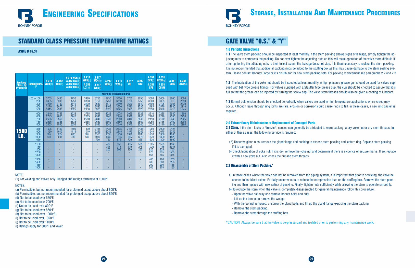
STANDARD CLASS PRESSURE TEMPERATURE RATINGS ASME B 16.34
Working Class by Pressures
Temperature, °F
A 216 WCB(a)
A 352 LCB(d)
A 216 WCC(a) A 352 LC2(d) A 352 LC3(d) A 352 LCC(e)
A 217 WC1(b)
A 352 LC1(d)
A 217 WC4(h)
A 217 WC5(i)
A 217 WC6(j)
A 217 WC9(j)
A 217 C5
A 217 C12
A 351 CF3(f)
A 351 CF8
A 351 CF3M(g)
A 351 CF8M
A 351 CF8C
A 351 CN7M(l)
Working Pressures in PSI
NOTE: (1) For welding end valves only. Flanged end ratings terminate at 1000°F.
NOTES: (a) Permissible, but not recommended for prolonged usage above about 800°F. (b) Permissible, but not recommended for prolonged usage above about 850°F. (d) Not to be used over 650°F. (e) Not to be used over 700°F. (f) Not to be used over 800°F. (g) Not to be used over 850°F. (h) Not to be used over 1000°F. (i) Not to be used over 1050°F. (j) Not to be used over 1100°F. (l) Ratings apply for 300°F and lower.
sTOrage, insTallaTiOn and mainTenanCe prOCedures
GATE VALVE “O.S.” & “Y”1.0 Periodic Inspections1.1 The valve stem packing should be inspected at least monthly. If the stem packing shows signs of leakage, simply tighten the ad-justing nuts to compress the packing. Do not over-tighten the adjusting nuts as this will make operation of the valve more difficult. If, after tightening the adjusting nuts to their fullest extent, the leakage does not stop, it is then necessary to replace the stem packing. It is not recommended that additional packing rings be added to the stuffing box as this may cause damage to the stem sealing sys-tem. Please contact Bonney Forge or it’s distributor for new stem packing sets. For packing replacement see paragraphs 2.2 and 2.3.
1.2 The lubrication of the yoke nut should be inspected at least monthly. A high pressure grease gun should be used for valves sup-plied with ball type grease fittings. For valves supplied with a Stauffer type grease cup, the cup should be checked to assure that it is full so that the grease can be injected by turning the screw cap. The valve stem threads should also be given a coating of lubricant.
1.3 Bonnet bolt tension should be checked periodically when valves are used in high temperature applications where creep may occur. Although leaks through ring joints are rare, erosion or corrosion could cause rings to fail. In these cases, a new ring gasket is required.
2.0 Extraordinary Maintenance or Replacement of Damaged Parts2.1 Stem. If the stem locks or "freezes", causes can generally be attributed to worn packing, a dry yoke nut or dry stem threads. In either of these cases, the following service is required:
a*) Unscrew gland nuts, remove the gland flange and bushing to expose stem packing and lantern ring. Replace stem packing if it is damaged.
b) Check lubrication of yoke nut. If it is dry, remove the yoke nut and determine if there is evidence of seizure marks. If so, replace it with a new yoke nut. Also check the nut and stem threads.
2.2 Disassembly of Stem Packing.*
a) In those cases where the valve can not be removed from the piping system, it is important that prior to servicing, the valve be opened to its fullest extent. Partially unscrew nuts to reduce the compression load on the stuffing box. Remove the stem pack-ing and then replace with new set(s) of packing. Finally, tighten nuts sufficiently while allowing the stem to operate smoothly.
b) To replace the stem when the valve is completely disassembled for general maintenance follow this procedure:- Open the valve half way and remove bonnet bolts and nuts.- Lift up the bonnet to remove the wedge.- With the bonnet removed, unscrew the gland bolts and lift up the gland flange exposing the stem packing.- Remove the stem packing.- Remove the stem through the stuffing box.
*CAUTION: Always be sure that the valve is de-pressurized and isolated prior to performing any maintenance work.
1500 LB.
-20 to 100 200 300 400 500
3705 3395 3270 3170 3015
3480 3300 3190 3075 2930
3750 3750 3640 3520 3325
3480 3300 3190 3075 2930
3750 3750 3640 3530 3325
3750 3750 3610 3465 3325
3750 3750 3640 3530 3325
3750 3750 3640 3530 3325
3750 3750 3640 3530 3325
3600 3000 2690 2485 2330
3600 3095 2795 2570 2390
3600 3310 3085 2880 2710
3000 2590 2330 2110 1945
600 650 700 750 800
2840 2745 2665 2535 2055
2755 2665 2560 2385 1955
3025 2940 2775 2535 2055
2755 2665 2560 2385 1955
3025 2940 2840 2660 2540
3025 2940 2840 2660 2540
3025 2940 2840 2660 2540
3025 2940 2840 2660 2540
3025 2940 2840 2660 2540
2210 2160 2110 2065 2030
2255 2210 2170 2135 2110
2580 2530 2485 2460 2435
1800 2250 2225 2200 2160
850 900 950
1000 1050
1595 1150 685 430
-
1490 1010 685 430
-
1595 1115 685 430
-
1490 1010 685 430
-
2435 2245 1575 1010 790
2435 2245 1595 1080 720
2435 2245 1930 1335 875
2435 1870 1370 995 720
2435 2245 1885 1270 855
1980 1945 1910 1770 1630
2090 2075 1930 1820 1800
2425 2245 1930 1820 1800
- - - - -
1100 1150 1200 1250 1300
- - -- -
- - -- -
- - - - -
- - - - -
- - - - -
480 325 205
- -
550 345 205
- -
495 310 170
- -
565 375 255
- -
1285 1030 825 670 565
1525 1185 925 735 585
1560 1045 755 565 375
- - - - -
1350 1400 1450 1500
- ---
- ---
- - - -
- - - -
- - - -
- - - -
- - - -
- - - -
- - - -
465 380 290 205
480 380 290 205
255 205 155 135
- - - -
30 31
2.3 The procedure to re-assembly the valve is as follows: Re-insert the stem through the stuffing box taking special care to reassemble parts in sequence. Insert the remaining packing rings into the stuffing box and compress using the gland and flange. Then, reassemble nuts and tighten. Note, the stem must slide freely through the stuffing box without applying excessive force. Finally, install the bonnet gasket making sure it is not damaged. The gasket should be replaced if there is any question as to its performance.
2.4 Raise the bonnet, making sure the stem is in a half open position, then connect disc to stem. Lower bonnet on to the valve body making sure that the disc fits exactly into body guides and the bonnet gasket is properly seated. Align holes and tighten bonnet nuts tak-ing care that excessive force is not used, possibly damaging the gasket. Hydrostatically test the valve to assure that there is no leakage.
2.5 Disassembly of yoke nutWhen necessary use the following procedure for disassembling and replacing yoke nut:
a) direct hand-operated valves (handwheel) - remove set screw; - unscrew handwheel nut; - remove handwheel; - unscrew yoke nut retaining nut, removing spot welds if necessary;
Reverse the procedure for re-assembly.
b) bevel gear operated valves - to remove the bevel gear from the valve, unscrew nuts and turn the handwheel in the open direction indicated by the arrow until the drive nuts are disengaged from the stem. - to check the condition of the drive nut or bearing, unscrew the retainer ring and remove the drive nut and bearing. If damaged, a new drive nut or bearing is necessary.
2.6 Wedge and SeatsLeakage through seats and wedges is not always easy to spot when valves are in service. However, when leaks are identified, immediate action is necessary. Any delay can permanently damage seat or wedge seal surfaces.
To repair or replace wedges or seats, the valve must be removed from the line and the following procedure should be applied: - make sure that the valve is not under pressure before unscrewing bonnet nuts; - remove the bonnet, being careful not to damage the gasket; - remove the bonnet when the wedge is in the half open position; - lift up the bonnet until the wedge is disconnected from the guides; - release the wedge from the stem.
If seat surfaces show signs of seizing, pitting, grooves or other defects not deeper that 0.8 mm (1/32") it is possible to repair seating surfaces to its original conditions by relapping the surface with line grain abrasive paste, creating a perfect tightness once again.
Defects having a depth exceeding 0.8 mm (1/32") cannot be repaired by lapping. In this case, parts must be replaced.
It is recommended that the face of the disc be blued to check for contact of seating surface after final lapping. For re-assembly of valves use the procedure outlined under para. 2.4.
sTOrage, insTallaTiOn and mainTenanCe prOCedures
GATE VALVE “O.S.” & “Y” (CONTINUED) GLOBE VALVE “O.S.” & “Y”1.0 Periodic Inspections
1.1 The valve stem packing should be inspected at least monthly. If the stem packing shows signs of leakage, simply tighten the adjusting nuts to compress the packing. Do not over-tighten the adjusting nuts as this will make operation of the valve more difficult. If, after tightening the adjusting nuts to their fullest extent, the leakage does not stop, it is then necessary to replace the stem pack-ing. It is not recommended that additional packing rings be added to the stuffing box as this may cause damage to the stem sealing system. Please contact Bonney Forge or it’s distributor for new stem packing sets. For packing replacement see paragraphs 2.2 and 2.3.
1.2 The lubrication of the yoke nut should be inspected at least monthly. A high pressure grease gun should be used for valves supplied with ball type grease fittings. For valves supplied with a Stauffer type grease cup, the cup should be checked to assure that it is full so that the grease can be injected by turning the screw cap. The valve stem threads should also be given a coating of lubricant.
1.3 Bonnet bolt tension should be checked periodically when valves are used in high temperature applications where creep may occur. Although leaks through ring joints are rare, erosion or corrosion could cause rings to fail. In these cases, a new ring gasket is required.
2.0 Extraordinary Maintenance or Replacement of Damaged Parts
2.1 Stem. If the stem locks or freezes, causes can generally be attributed to worn packing, a dry yoke nut or dry stem threads. In either of these cases, the following service is required:a*) Unscrew gland nuts, remove gland flange and bushing to expose stem packing and lantern ring. Replace stem packing if it is damaged.b) Check lubrication of yoke nut. If it is dry, remove the yoke nut and determine if there is evidence of seizure marks. If so, replace it with a new yoke nut. Also check the nut and stem threads.
2.2 Disassembly of Stem Packing.*a) In those cases where the valve cannot be removed from the piping system, it is important that prior to servicing, the valve be opened to its fullest extent. Partially unscrew nuts to reduce the compression load on the stuffing box. Remove the stem packing and then replace with new set(s) of packing. Reassemble plug and gland flange. Finally, tighten nuts sufficiently while allowing the stem to operate smoothly.
b) To replace the stem when the valve is completely disassembled for general maintenance follow this procedure: - Open the valve and remove the bonnet bolts and nuts. - With the bonnet removed, unscrew the gland bolts and lift up the gland flange exposing the stem packing. - Remove the stem packing. - Remove handwheel, then turn stem to release it from yoke nut and remove from stuffing box. - Check condition of back-seat bushing for seizure marks. If apparent, order replacement parts.
*CAUTION: Always be sure that the valve is de-pressurized and isolated prior to performing any maintenance work.
32
sTOrage, insTallaTiOn and mainTenanCe prOCedures
33
2.3 The procedure to re-assembling the valve is as follows: Re-insert the stem through the stuffing box, taking special care to reassemble parts in sequence. Insert the remaining packing rings into the stuffing box and compress using the gland ring and flange. Then, reassemble nuts and tighten. Note, the stem must slide freely through the stuffing box without applying excessive force. Finally, install the bonnet gasket making sure it is not damaged. The gasket should be replaced if there is any question as to its performance.
2.4 Raise the bonnet assembly, making sure the stem is in the fully open position. Lower bonnet on to the valve body making sure that the disc fits exactly into body guides and the bonnet gasket is properly seated. Align holes and tighten bonnet nuts taking care that excessive force is not used, possibly damaging the gasket. Hydrostatically test the valve to assure that there is no leakage.
2.5 Disassembly of yoke nutWhen necessary use the following procedure for disassembling and replacing yoke nut:
a) direct hand-operated valves (handwheel) - remove set screw; - unscrew handwheel nut; - remove handwheel; - unscrew yoke nut retaining nut, removing spot welds if necessary; - Reverse the procedure for re-assembly.
b) bevel gear operated valves - to remove the bevel gear from the valve, unscrew nuts and turn the handwheel in the open direction indicated by the arrow until the drive nuts are disengaged from the stem. - to check the condition of the drive nut or bearing, unscrew the retainer ring and remove the drive nut and bearing. If damaged, a new drive nut or bearing is necessary.
2.6 Disc and SeatsLeakage through disc and seats is not always easy to spot when valves are in service. However, when leaks are identified, immediate action is necessary. Any delay can permanently damage seat or wedge seal surfaces.
To repair or replace the disc or seats, the valve must be removed from line, then use the following procedure: - make sure that the valve is not under pressure before unscrewing bonnet nuts; - remove bonnet, being careful not to damage the gasket; - remove bonnet when disc is in full open position; - lift up bonnet
If seat surfaces show signs of seizing, pitting, grooves or other defects not deeper that 1.5 mm (1/16") it is possible to repair seating surfaces to its original conditions by relapping the surface with line grain abrasive paste, creating a perfect tightness once again. Defects having a depth exceeding 1.5 mm (1/16") cannot be repaired by lapping. In this case, parts must be replaced.
It is recommended that the face of the disc be blued to check for contact of seating surface after final lapping. For re-assembly of valves use the procedure outlined under para. 2.4.
GLOBE VALVE “O.S.” & “Y” (CONTINUED) SWING CHECK VALVESNo periodic maintenance is necessary. If gasket leaks are detected, correct using the following procedure.
1 - Disassemble all cover bolts and nuts.
2 - For check valves in sizes 16" and larger, lift up the cover by using a lever inserted into the drilled and tapped cover hole. For valves in sizes 14" and smaller, use one or two bolts and nuts inserted into cover holes and, using adequate force, move the cover upwards.
3 - Check that the hinge, nut, and pin are in good condition and firmly connected. Replace damaged parts as necessary.
4 - Lift and remove the disc-hinge assembly. Movement should be free and not hindered by any malfunction of the hinge pin. Where disc travel is not sufficiently smooth, remove plugs or blind flanges and then remove hinge pin. Check surface for seizure marks. If marks are deeper than 1.5 mm (1/16"); re-machine hinge pin and re-assemble. If defect depth is greater than 1.5 mm (1/16") a new hinge pin is necessary. When reassembling hinge pin, it is recommended that the disc be removed by loosening nut.
5 - When leakage is due to deterioration of seal surfaces caused by corrosion or foreign substances, it must be determined whether the disc or seat seal are the cause.
a) Deterioration of disc surfaces: Disassemble disc by removing nut and washer. Repair surface by grinding and relapping using fine grain abrasive paste.
b) Deterioration of seat seal surfaces:When seal surfaces are damaged and defects are confined to a small area but are not deeper than 0.8 mm (1/32"), the seal surface can be repaired. The recommended method is to use a cast iron strap with an outside diameter matching the valve’s raceway. Then using a fine grain abrasive paste between the strap and raceway, it is rotated on the seat to restore original tight-ness. When defects are deeper than 0.8 mm (1/32") and found on the entire seal surface, a new seat is required. To replace the new seat, use preferably a pneumatic tool with a shape to match the dimensions of the valve seat. It is recommended that an anti seizing compound be used when installing the replacement seat to make threading it in to the body easier.
CAUTION: Always be sure that the valve is de-pressurized and isolated prior to performing any maintenance work.
34 35
sTOrage, insTallaTiOn and mainTenanCe prOCedures
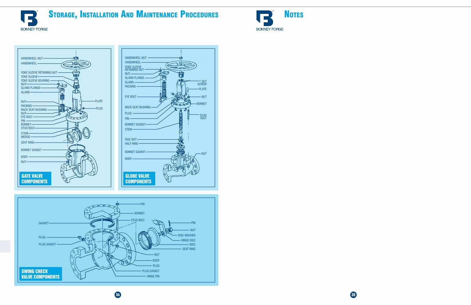
PLATE
PLUG
HANDWHEEL NUT
HANDWHEEL
YOKE SLEEVE RETAINING NUTYOKE SLEEVE
NUTYOKE SLEEVE BEARING
GLAND FLANGEGLAND
NUTPACKINGBACK SEAT BUSHINGNUTEYE BOLTPINBONNETSTUD BOLT
STEMWEDGE
SEAT RING
BONNET GASKET
NUT
BODY
GATE VALVE COMPONENTS
GLOBE VALVE COMPONENTS
PLATE
NUT
HANDWHEEL NUTHANDWHEEL
YOKE SLEEVE RETAINING NUTNUTGLAND FLANGEGLANDPACKING
BACK SEAT BUSHING
PLUG
EYE BOLT
PIN
BONNET GASKET
STEM
DISC NUTHALF RING
BONNET GASKET
BODY
SET SCREW
BONNET
STUD BOLT
NUT
SWING CHECK VALVE COMPONENTS
PIN
NUT
DISC WASHER
HINGE DISC DISC
SEAT RING
PIN
BONNET
STUD BOLT
PLUG
PLUG GASKET
GASKET
NUT
BODY
PLUG GASKET
PLUG
HINGE PIN
nOTes

36
nOTesGENERAL TERMS AND CONDITIONS OF SALE OF: BONNEY FORGE (HEREAFTER REFERRED TO AS “BF”)
Note: The material in this catalog is for general information. For specific performance data and proper material selection, consult your Bonney Forge representative. Although every attempt has been made to ensure that the information contained in this catalog is correct, Bonney Forge reserves the right to change designs, materials or specifications without notice.
CVI 7.16 (1.5M)
WARRANTY All products are warranted to be free from manufacturing defects for a period of one (1) year from date of shipment, and any found to be defective within that period will be replaced without charge, provided (1) that the product was used as recommended and in accordance with approved installation and operating practices. (2) that its failure resulted from a manufacturing defect and not from damage due to corrosive, abrasive, or other wear normally to be expected in the services involved. (3) that the product was not modified or changed (unless written approval was give by BF), and (4) that written notice of such defect is delivered to BF during such one (1) year period. BF will not be responsible for any labor, equipment, engineering or related costs or liability associated with the replacement of a defective product. The Uniform Commercial Code shall not apply to the sale, nor the Michigan statutes adopting the Uniform Commercial Code. This express warranty is in lieu of and excludes all other warranties, guarantees, or representations, expressed or implied. There are no implied warranties of merchantability or of fitness for a particular purpose.
EXCLUSIONS Do not use BF products in aircraft or aerospace applications. No warranties, guarantees or representations of any kind are made with respect to such applications. The Purchaser assumes all risks of any use is such applications and will indemnify and hold harmless BF against and from any claims, costs (including attorneys fees) and liabilities arising out of such use.
PURCHASER’S REMEDIES
The Purchaser’s remedies with respect to any product furnished by BF hereunder that is found not to be in conformity with the terms and conditions of the contract because of breach of contract, breach of express or implied warranty, or negligence shall be limited exclusively to the right of replacement of such defective product or, at our option, repayment of our sale price of the product. In no event shall BF be liable for claims (based upon breach of contract, breach of express or implied warranty, or negligence) for any other damages, whether direct, immediate, foreseeable, consequential, or special or for any expenses incurred by reason of the use or misuse, sale or fabrication of products which do or do not conform to the terms and conditions of the contract.
PRICES Prices, and other terms of sale and payment, are subject to change without notice. Unless a contrary provision appears in this price schedule, quotation or order acknowledgment, prices may be withdrawn without notice at any time. Stenographic or clerical errors are subject to correction.
ACCEPTANCE OF ORDERS
All orders are subject to BF credit department approval prior to acceptance by BF. No assignment of the Purchaser’s rights may be made without the written consent of BF.
REMITTANCES All accounts are payable in United States funds, free of exchange, collection or any other charges. If in the sole discretion of BF the financial condition of the Purchaser at any time so requires, BF retains the right to require full or partial payment in advance.
PARTIAL SHIPMENTS AND PAYMENTS
BF reserves the right to make partial shipments from time to time and to render invoices therefore which shall be due and payable as provided in said invoices and the paragraph entitled. “Remittances” if the Purchaser becomes overdue in any such partial payment, BF shall be entitled to suspend work and or avail itself of other legal remedies.
TAXES Unless otherwise specifically noted, the amount of any sale, use , occupancy, excise tax or other tax, of any nature, federal, state, or local for which BF is legally liable, either initially or through failure of payment by Purchaser, shall be added or be in addition to the price quoted and Purchaser agrees to pay the same to BF.
SHORTAGES & DAMAGES IN TRANSIT
Claims for shortages must be made in writing within ten days after receipt of shipment, but loss of or damage to material in transit is the responsibility of the carrier.
DELAYS All promises of shipment are estimated as closely as possible, and we will use our best efforts to ship within the time promised but do not guarantee to do so, and assume no liability for no doing so. Materials stated to be in stock are subject to prior sale.
CANCELLATION & SUSPENSION
The order or contract is subject to cancellation or instructions to suspend or delay work or delivery only upon receipt of written notification and with our consent, and upon agreement to pay BF’s adjustment charge. Order’s for special products ( usually “price of application” items) may be changed and or cancelled only upon receipt of written instructions with a facit understanding and agreement to make payment for material used and work already performed.
RETURN OF MATERIAL
No product of our manufacture may be returned without written consent. All goods returned are subject to a handling charge plus freight in both directions and charges for any required reconditioning, unless otherwise specified in writing by BF.
PATENTS The Purchaser will indemnify and hold harmless BF against and from any claims, costs (including attorneys fees) and liabilities arising out of any suit alleging infringement of any United States by any product supplied by BF under the contract and made in accordance with the design and or specification furnished by the Purchaser to BF.
GOVERNING LAW The contract shall be governed by, construed, and enforced in accordance with the laws of the Commonwealth of Pennsylvania.
NO WAIVER The failure of BF to insist, in any one or more instances upon the performance of any of the terms, covenants, or conditions of the contract or to exercise any right thereunder shall not be construed as a waiver or relinquishment of the future performance of any such term, covenant or condition or the future exercise of such rights, nor shall it be deemed to be a waiver or relinquishment of any other term, covenant, or condition or the exercise of any other rights under the contract.
DIES, TOOLS AND PATTERNS
Dies, tools and patterns required to produce the article quoted on shall remain the property of BF. Preparation charges for dies, tools and patterns represent only a portion of cost. Payment of such charge does not give you any right, title, or interest in such dies, tools, or other products of preparation. We will not be responsible for retention of dies or patterns on which no orders are received for two years or more.
FORCE MAJEURE Any delays in or failure of performance of BF shall not constitute default or give rise to any claims for damages if and to the extent that such delay or failure is caused by occurrences beyond the control of BF, including but not limited to acts of God or the public enemy, expropriation or confiscation of facilities, compliance with any order or request of any governmental authority, acts of war, rebellion or sabotage or damage result-ing therefrom, embargoes or other export restrictions, fires, floods, explosions, accidents, breakdowns, riots or strikes or other conceived acts of workmen, whether direct or indirect, or any other causes whether or not of the same class or kind as those specifically above named which are not within the control of BF and which by the exercise of reasonable diligence, BF, is unable to prevent or provide against.
PURCHASER’S ACCEPTANCE OF ABOVE CONDITIONS
The contract shall be subject to the terms and conditions contained or referred to in BF’s price schedule, quotation or order acknowledgment and to no others whatsoever. No waiver, alteration, or modification of the terms and conditions in this price schedule, quotation or order acknowledg-ment shall be binding unless in writing and signed by an authorized representative of BF.