
Case study of solutions to screw compressor package vibrations
19
Case study of solutions to screw compressor package vibrations By Wally Bratek, MSc, PEng Principal Consultant Wood Calgary, Canada W[email protected] Umeet Bhachu, P.Eng, PMP, CMRP Sr. Rotating Equipment Engineer Pembina Pipeline Corporation Edmonton, Canada [email protected] Jeffery Barss Field Analyst Wood Calgary, Canada [email protected] GMRC Gas Machinery Conference 29 September to 2 October 2019 San Antonio, TX
Transcript of Case study of solutions to screw compressor package vibrations

Case study of solutions to screw compressor
package vibrations
By
Wally Bratek, MSc, PEng
Principal Consultant
Wood
Calgary, Canada
Umeet Bhachu, P.Eng, PMP, CMRP
Sr. Rotating Equipment Engineer
Pembina Pipeline Corporation
Edmonton, Canada
Jeffery Barss
Field Analyst
Wood
Calgary, Canada
GMRC Gas Machinery Conference
29 September to 2 October 2019
San Antonio, TX

Case study of solutions to screw compressor package vibrations Page 2
GMRC Gas Machinery Conference 2019 Wood and Pembina
Abstract
Screw compressors are used in industrial applications requiring large volumes of gas at high compression ratios. This
rotary-type positive-displacement machine produces a steadier flow than reciprocating compressors, however, risks of
high-frequency vibration and fatigue failure due to the compression process remain and can be especially challenging to
solve.
This paper presents a case study involving three oil-flooded screw compressor packages in propane service. High
vibration on the packages led to excessive noise and failures on small-bore connections. The case study describes the
initial measurements of vibration and pulsation, multi-channel shell-mode vibration measurements of the discharge
separator vessels, and computer simulations of the pulsation and mechanical systems. The data will demonstrate how
compressor volume index (VI) and slide valve position influence pulsation and resonances and will quantify the effects of
constrained-layer damping to reduce mechanical vibration. Optimized solutions to reduce the pulsation and vibration
are presented, including field data of the initial and modified systems.
Purchasers and operators of screw compressors can apply the recommendations presented in this case study to
minimize the risk of vibration-related failures on screw compressor packages. Relevant API and industry guidelines are
also discussed.

Case study of solutions to screw compressor package vibrations Page 3
GMRC Gas Machinery Conference 2019 Wood and Pembina
Introduction
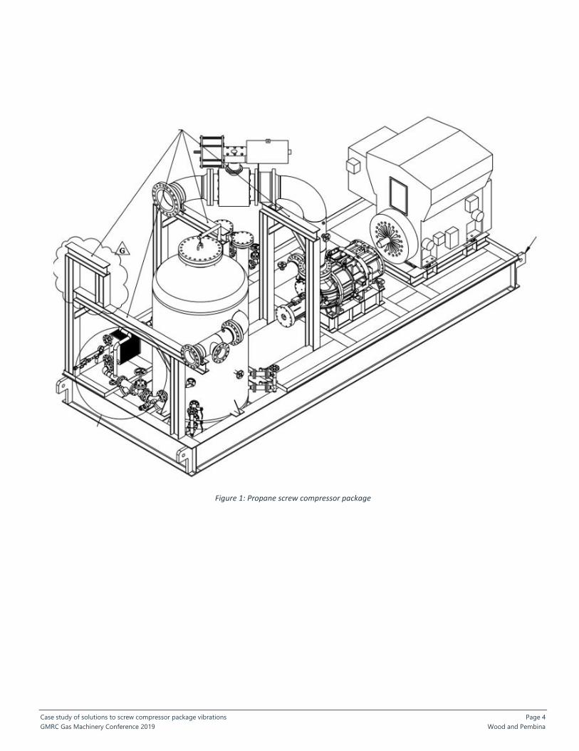
In 2015, Pembina Pipeline Corporation had commissioned three propane refrigeration compressors at a facility in
Alberta, Canada. The Frick screw compressors are driven by 2500 HP fixed-speed electric motors and operate at 3565
RPM. Capacity is controlled by slide valves on the screw compressors, resulting in flows ranging from 7.8 to 28.4 mmscfd.
The operating temperatures and pressures are summarized in Table 1. A drawing of one of the compressor packages is
shown in Figure 1.
Table 1 – Operating conditions
Suction pressure Suction temperature Discharge pressure Discharge temperature
41.7 – 42.5 psig 23 F 165.7 – 198.8 psig 158 F
288 – 293 kpag -5 C 1140 – 1370 kpag 70 C
The compressors provide propane refrigeration cooling for a de-ethanizer system in NGL (natural gas liquids) production
facility. The compressors are running in a closed loop cycle to cool the de-ethanizer column, which then produces
ethane. The vapor pressure of ethane is high, and hence, in order to liquify this, it is necessary to cool the product or
increase the pressure. In this case, the refrigeration loop is cooling the product to ensure a liquid phase recovery of the
ethane.
The screw compressors were chosen based on their lower cost compared to centrifugal compressors, which are
sometimes applied in such applications. (The pressure drop across the refrigeration loop is too small for a reciprocating
compressor.) While centrifugal compressors are less prone to gas pulsations than positive displacement machines, they
can be higher in cost due to their required anti-surge systems and gas seals.
Overall the compressor packages initially operated as designed without major problems. During the initial stages of
commissioning, the VI had to be tuned by the manufacturer and set to ensure that the overall compressor frame
vibration was within an acceptable range. Even though the compressor vibration was acceptable, high-frequency
vibration was observed on some of the piping spans and fatigue cracks had formed on some small-bore connections.
Excessive vibration and noise were also observed emanating from the discharge oil separator vessel wall. These types of
piping and vessel issues are common on screw compressor packages over 1000 HP. This case study highlights the field
analysis, design simulations and solutions that were employed to resolve the residual pulsation and vibration issues and
allow for a safe and efficient operation of the compressor packages.
Case study of solutions to screw compressor package vibrations Page 4
GMRC Gas Machinery Conference 2019 Wood and Pembina
Figure 1: Propane screw compressor package
Case study of solutions to screw compressor package vibrations Page 5
GMRC Gas Machinery Conference 2019 Wood and Pembina
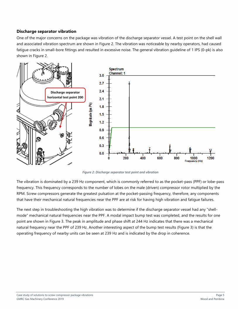
Discharge separator vibration
One of the major concerns on the package was vibration of the discharge separator vessel. A test point on the shell wall
and associated vibration spectrum are shown in Figure 2. The vibration was noticeable by nearby operators, had caused
fatigue cracks in small-bore fittings and resulted in excessive noise. The general vibration guideline of 1 IPS (0-pk) is also
shown in Figure 2.
Figure 2: Discharge separator test point and vibration
The vibration is dominated by a 239 Hz component, which is commonly referred to as the pocket-pass (PPF) or lobe-pass
frequency. This frequency corresponds to the number of lobes on the male (driven) compressor rotor multiplied by the
RPM. Screw compressors generate the greatest pulsation at the pocket-passing frequency, therefore, any components
that have their mechanical natural frequencies near the PPF are at risk for having high vibration and fatigue failures.
The next step in troubleshooting the high vibration was to determine if the discharge separator vessel had any “shell-
mode” mechanical natural frequencies near the PPF. A modal impact bump test was completed, and the results for one
point are shown in Figure 3. The peak in amplitude and phase shift at 244 Hz indicates that there was a mechanical
natural frequency near the PPF of 239 Hz. Another interesting aspect of the bump test results (Figure 3) is that the
operating frequency of nearby units can be seen at 239 Hz and is indicated by the drop in coherence.
Discharge separator
horizontal test point 200

Case study of solutions to screw compressor package vibrations Page 6
GMRC Gas Machinery Conference 2019 Wood and Pembina
Figure 3: Discharge separator modal impact bump test
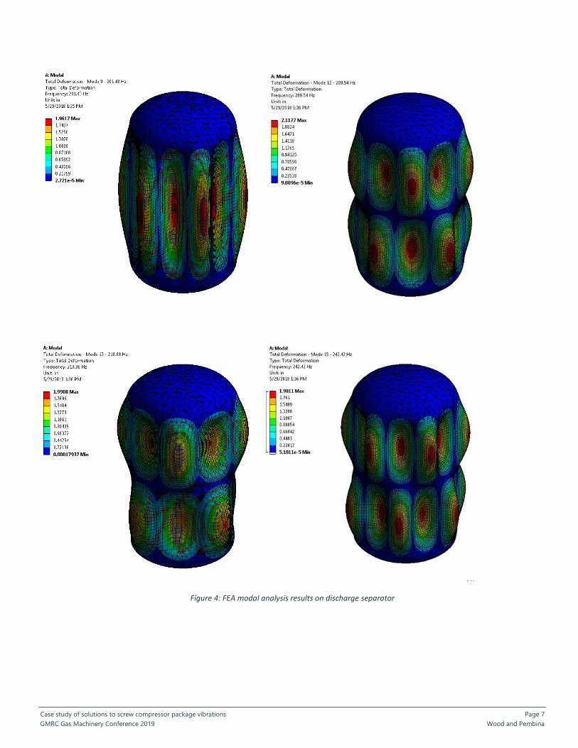
A finite element analysis for a simplified vessel model confirmed numerous shell-mode mechanical natural frequencies
near the PPF of 239 Hz. The shell mode shapes corresponding to frequencies of 201 Hz, 209 Hz, 219 Hz, and 242 Hz are
shown in Figure 4. The field tests and FEA models confirmed that the high vibration was caused by PPF pulsation and
mechanical resonance of the discharge separator shell wall.
Case study of solutions to screw compressor package vibrations Page 7
GMRC Gas Machinery Conference 2019 Wood and Pembina
Figure 4: FEA modal analysis results on discharge separator

Case study of solutions to screw compressor package vibrations Page 8
GMRC Gas Machinery Conference 2019 Wood and Pembina
Another notable aspect of the discharge separator vibration was that the vibration amplitude varied significantly with
slide valve position(see Table 2). Since the compressor is fixed speed, the change in vibration was not the result of
tuning-in a mechanical resonance. Rather, the change in vibration was likely due to a change in the pulsation energy in
the compressor discharge system.
Table 2 – Discharge separator vibration with slide valve position
Slide valve position/load
percentage
Vibration amplitudes (in/s 0-pk)
90 1.00
80 0.71
70 1.3
60 2.12
50 2.45
40 2.68
30 2.54
20 2.55
10 2.65
Pulsation energy changes with slide valve position because the actual compressor volume-index (VI) varies as the slide
valve is moved. The compressor VI determines the compression ratio that exists internally inside the compressor. This
internal compression ratio occurs regardless of the actual operating pressures that are set by the process system design.
When the screw compressor compression ratio, as determined by the VI, does not match the operating pressures, then a
condition of over-compression or under-compression exists, see Figure 5 from Pillis5. For a further discussion of capacity
control and VI see referenced papers by Bruce3 and Smith1. Generally, the greater the over-compression, the larger the
pulsation source strength at the compressor and the higher the pulsation will be in the system. Therefore, slight under-
compression leads to fewer pulsation-induced vibration issues than does over-compression. API 688 provides guidelines
for the amount of overpressure that is desirable. For this application, API 688 would allow 20% of discharge pressure in
over-compression.

Case study of solutions to screw compressor package vibrations Page 9
GMRC Gas Machinery Conference 2019 Wood and Pembina
Figure 5: Screw compressor over-compression and under-compression
Since the position of the slide valve changes the VI of the compressors, it is common to observe pulsation energy
changing with slide valve position as well, as occurred on these screw compressors.
Pulsation simulation
As discussed previously, the likely cause of pulsation energy in the discharge system changing with slide valve position is
due to changes in the compressor Vi. However, it is also possible that an acoustic resonance exists in the system and is
worse at reduced flows due to a decrease in acoustic damping associated with reduced flow velocity. Therefore, a
pulsation model of the discharge system was constructed to investigate the possibility of acoustic resonance. The
pulsation model would also be used to determine if pulsation mitigation devices such as orifice plates or resonators
would be effective at reducing the pulsation in the system.
Pulsation studies on screw compressors differ from pulsation studies on reciprocating compressors due to the higher
frequencies associated with screw compressor excitation. Acoustic simulations in piping systems typically utilize a plane-
wave assumption. Plane wave pulsation means the pressure is the same on a plane or cross-section of the pipe or vessel.
Therefore, a plane-wave simulation will not be able to make predictions about transverse-wave acoustic phenomena,
which can occur at the high frequencies associated with screw compressors. However, despite this limitation, there is still
value in completing the plane-wave simulation to gain insight into the pulsation in the system, and API specifications
such as API-688 recommend pulsation simulations for higher power applications. The simulations have been used
effectively to design orifice plates and resonators and reduce pulsation in many systems. In this case, the average speed
of sound at discharge conditions is 672 ft/s. Therefore, at 239 Hz the wavelength is 2.8 ft. The diameter of the discharge
piping is 10”. Therefore, transverse waves are not expected in the discharge piping, and the plane wave simulation is
accurate at the pocket passing frequency.
The pulsation source strength in screw compressor simulations is also a significant source of uncertainty. In this case the
pulsation source strength was calculated based on the known flow of the compressor and the amount of time that one
of the compressor passages was exposed to the discharge port. A plot of the discharge system pulsation model with the
pulsation amplitudes at the PPF is shown in Figure 6.

Case study of solutions to screw compressor package vibrations Page 10
GMRC Gas Machinery Conference 2019 Wood and Pembina
Figure 6: Pulsation simulation model, discharge system
The API 619 pulsation guideline for this case is 4 psi, pk-pk. Pulsation amplitudes at the compressor discharge are
greater than the API 619 guideline. However, inside the discharge separator vessel, pulsation does appear to meet the
guideline per the simulation, as long as transverse acoustic resonances are not present inside the discharge separator.
Note that the transverse acoustic modes associated with the separator as described in Blevins6. did not match the pocket
passing frequency in this case, therefore, transverse acoustic amplification was not expected.
Field measurements on the discharge separator vessel agree with the simulation models in that pulsation is generally low
inside the vessel. See Figure 7 for a field pulsation measurement. The highest pulsation amplitude is at the pocket
passing frequency of 239 Hz as is typical in screw compressors. Since the field measurements showed low pulsations
inside the discharge separator, we were confident that there was not a significant transverse acoustic wave pulsation
resonance inside the vessel.
Termination node
Discharge Oil
separator
Separator inlet
flange
Screw
compressor
source
Field pressure
measurement
point, see
Figure 7

Case study of solutions to screw compressor package vibrations Page 11
GMRC Gas Machinery Conference 2019 Wood and Pembina
Figure 7: Pulsation measurement on separator shell (pk-pk)
The acoustic simulation was used to test various pulsation attenuation modifications such as orifice plates, a quarter-
wave resonator and a Helmholtz filter. The optimal location for an orifice plate in this case was at the screw compressor
discharge flange. The proposed quarter-wave resonator and Helmholtz filter geometry are shown in Figure 8. The
pulsation amplitude at the separator inlet flange as well as shaking forces in the piping system were used as metrics to
compare the outcome of the various proposed solutions. A summary of the pulsation and associated pressure drop
results are presented in Table 3.
Pulsation at PPF is 1.6
psi pk-pk as measured
in the field

Case study of solutions to screw compressor package vibrations Page 12
GMRC Gas Machinery Conference 2019 Wood and Pembina
Figure 8: Pulsation mitigation options
Quarter-wave resonator Helmholtz filter
Case study of solutions to screw compressor package vibrations Page 13
GMRC Gas Machinery Conference 2019 Wood and Pembina
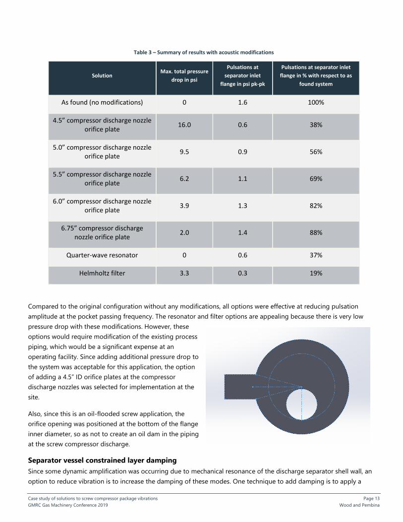
Table 3 – Summary of results with acoustic modifications
Solution Max. total pressure
drop in psi
Pulsations at
separator inlet
flange in psi pk-pk
Pulsations at separator inlet
flange in % with respect to as
found system
As found (no modifications) 0 1.6 100%
4.5” compressor discharge nozzle orifice plate
16.0 0.6 38%
5.0” compressor discharge nozzle orifice plate
9.5 0.9 56%
5.5” compressor discharge nozzle orifice plate
6.2 1.1 69%
6.0” compressor discharge nozzle orifice plate
3.9 1.3 82%
6.75” compressor discharge nozzle orifice plate
2.0 1.4 88%
Quarter-wave resonator 0 0.6 37%
Helmholtz filter 3.3 0.3 19%
Compared to the original configuration without any modifications, all options were effective at reducing pulsation
amplitude at the pocket passing frequency. The resonator and filter options are appealing because there is very low
pressure drop with these modifications. However, these
options would require modification of the existing process
piping, which would be a significant expense at an
operating facility. Since adding additional pressure drop to
the system was acceptable for this application, the option
of adding a 4.5” ID orifice plates at the compressor
discharge nozzles was selected for implementation at the
site.
Also, since this is an oil-flooded screw application, the
orifice opening was positioned at the bottom of the flange
inner diameter, so as not to create an oil dam in the piping
at the screw compressor discharge.
Separator vessel constrained layer damping
Since some dynamic amplification was occurring due to mechanical resonance of the discharge separator shell wall, an
option to reduce vibration is to increase the damping of these modes. One technique to add damping is to apply a
Figure 9: Recommended orifice plate

Case study of solutions to screw compressor package vibrations Page 14
GMRC Gas Machinery Conference 2019 Wood and Pembina
constrained layer damping clamp to the vessel, which consists of a thin layer of damping material and with a steel clamp.
With this configuration, vibratory bending in the shell wall creates deformation and shear of the damping material, which
in turns increases the damping associated with the shell wall modes (Smith1).
For this application 1/8” neoprene was used as the damping material because of its high damping ratio (~50%) and
relatively large allowable operating temperature range of -30ºF to 225ºF. For some applications, the relatively low elastic
modulus of neoprene makes the material ineffective at adding damping to piping systems, however, in this case it
proved to be effective so long as the neoprene layer was thin enough and in compression between the vessel and the
steel clamp. The steel clamp was 1/2” thick.
Figure 10: Constrained layer damping clamp on discharge separator
1/8” Neoprene
Layer
Constrained Layer
Damping Clamp

Case study of solutions to screw compressor package vibrations Page 15
GMRC Gas Machinery Conference 2019 Wood and Pembina
Vibration amplitudes on the separator and noise levels in the surrounding area were generally lower after the clamp was
installed. The decrease in vibrations was observed throughout the full range of load steps, as shown in Table 4. Note that
the vibration measurements shown in Table 4 do not include any acoustic/pulsation modifications such as the orifice
plate described previously.
Table 4 – Discharge separator vibration with damping clamp, Test Point 200
Slide valve position/load
percentage
Original vibration amplitudes (in/s 0-pk)
With damping clamp vibration amplitudes
(in/s 0-pk)
90 1.00 0.56
80 0.71 0.71
70 1.3 0.96
60 2.12 1.45
50 2.45 1.64
40 2.68 1.07
30 2.54 0.82
20 2.55 0.71
10 2.65 0.96
One challenge with adding the constrained layer damping clamp to the existing vessel was positioning the clamp such
that it avoided the many nozzles for instrumentation and level gages, etc. Therefore, the clamp was only effective locally
where it was applied, but there was still high vibration lower on the vessel as shown in Figure 11.
Also, the FEA results shown in Figure 4 for 242 Hz show that the vibration is “nodal” (has zero movement) at the
centerline of the vessel. The 242 Hz mode is the most likely mode shape occurring in the field since its frequency is
closest to the PPF. Since deformation is minimal at the centreline of the vessel, the constrained layer damping clamp at
this location was not optimal. The damping material must be deformed and positioned at a location of high vibration to
add significant damping to vessel modes.
The residual high vibration lower on the shell also occurred near the inlet nozzle connection of the discharge separator,
and this was a concern due to the stress concentration of the nozzle weld. Therefore, a second constrained layer
damping clamp was recommended near the discharge separator inlet nozzle connection as indicated in Figure 11.

Case study of solutions to screw compressor package vibrations Page 16
GMRC Gas Machinery Conference 2019 Wood and Pembina
Figure 11: Vibration on separator vessel shell, after damping clamp installed
The discharge separator vessel with the 2nd constrained layer damping clamp installed is shown in Figure 12. For the final
set of pulsation and vibration measurements, the 2nd constrained layer damping clamp is installed, and the
recommended 4.5” orifice plate was also installed at the compressor outlet nozzle.
Installed clamp
Additional clamp
recommended
High shell
vibration lower
on vessel (1.9 IPS)

Case study of solutions to screw compressor package vibrations Page 17
GMRC Gas Machinery Conference 2019 Wood and Pembina
Figure 12: Discharge separator vessel with two constrained layer damping clamps
A plot of the pulsation measurement with the orifice plate installed is shown in Figure 13. Pulsations had dropped from
1.6 psi, pk-pk to 0.45 psi, pk-pk. Therefore, the orifice plate was effective at reducing the latent pulsation in the system.
The vibration amplitudes on the vessel shell with both the second damping clamp and also the orifice plate installed are
summarized in Table 5. The vibration on the shell wall was successfully reduced to below the 1 IPS vibration guideline.

Case study of solutions to screw compressor package vibrations Page 18
GMRC Gas Machinery Conference 2019 Wood and Pembina
Figure 13: Pulsation measurement on separator shell, after orifice plate installed (pk-pk)
Table 5 – Discharge separator vibration with damping clamps and 4.5” orifice plate, test point 200
Slide valve position/load
percentage
Original vibration
amplitudes (in/s 0-pk)
With damping clamp vibration amplitudes
(in/s 0-pk)
With (2) damping clamps and orifice plate
vibration amplitudes (in/s 0-pk)
90 1.00 0.56 0.61
80 0.71 0.71 0.47
70 1.3 0.96 0.44
60 2.12 1.45 0.62
50 2.45 1.64 0.85
40 2.68 1.07 0.76
30 2.54 0.82 0.45
20 2.55 0.71 0.33
10 2.65 0.96 0.44

Case study of solutions to screw compressor package vibrations Page 19
GMRC Gas Machinery Conference 2019 Wood and Pembina
Conclusions and recommendations
The case study demonstrates that, like reciprocating compressors, screw compressors can have pulsation and vibration
problems since they are positive-displacement machines. Industry standards such as API 619 and API 688 provide
methods to minimize the risks of vibration, and pulsation simulations are recommended for compressors larger than
1000 HP / 750 kW. Orifice plates, resonators and pulsation filters (bottles) can effectively reduce pulsation and vibration
in screw compressor applications. Also, it is important that the VI of the compressors match the expected operating
pressures to avoid excessive over- or under-compression.
Regarding mechanical considerations, small-bore connections and vessel shells are at risk of having vibration issues due
to the higher-frequency pulsation associated with screw compressors. To reduce vibration risks, minimize the number of
small-bore connections and instrumentation and apply robust, proven designs. Also, design vessel shell walls with a 20%
separation margin between the shell-mode mechanical natural frequencies and pocket-passing frequency. Lastly, due to
the high frequency of screw compressors, vibration problems are often due to mechanical resonance of lightly damped
piping components. Therefore, the addition of damping to systems can be beneficial to reduce vibration amplitudes.
Acknowledgements
The authors recognize the contributions from Wood’s field engineers Kevin Park and Michal Gaca for conducting some
of the site testing, and Wood’s acoustic engineer Sina Daneshvar for completing the acoustic simulations. The authors
would also like to thank engineers from Pembina including Albert Mausolf and George Mahovlic for their help and
support for this project.
References
1. Smith, Donald R., Engineering Dynamics Incorporated, Pulsation, Vibration, and Noise Issues with Wet and Dry
Screw Compressors. Proceedings of the Fortieth Turbomachinery Symposium, September 12-15, 2011, Houston,
Texas
2. Price, S.M., Smith, Donald R., Engineering Dynamics Incorporated, Sources and Remedies of High-Frequency
Piping Vibration and Noise. Proceedings of the 28th Turbomachinery Symposium
3. Bruce, Trent, Sage Energy Corp, Screw Compressors: Misconception or Reality, A discussion of the Application
and Operation of Oil Flooded Rotary Screw Compressors and a Comparison to the Conventional Reciprocating
Machines, http://sageenergy.ca/wp-content/uploads/2012-Paper-Screw-Compressors.pdf
4. Pillis, J.W, Frick, Basics of Operation, Application & Troubleshooting of Screw Compressors, January 1998
5. Rahnama, R. Eberle, K, Maculo, Martin, Brink, E, Case Study of Solving Screw Compressor Package Vibrations,
Proceedings of Gas Machinery Conference 2017, Pittsburgh, PA
6. Blevins, Robert D., Formulas for Natural Frequency and Mode Shape, 1979, New York, Krieger Pub Co