Case Study-Based Challenges of Quality Concrete Finishing ...
10
Case Study-Based Challenges of Quality Concrete Finishing for Architecturally Complex Structures Juan D. Manrique 1 ; Mohamed Al-Hussein 2 ; Avi Telyas 3 ; and Geoff Funston 4 Abstract: This paper focuses on the procedure utilized in the construction of tilt-up irregular concrete panels that are constructed on-site using concrete slabs and wooden formwork. The case study required high-quality concrete finishing. The erection and installation procedure called for a maximum panel-to-panel joint tolerance of 1.27 cm 0.5 in., often 90° joints between panels. To meet precision requirements, the casting slabs were leveled and flattened with laser screed technology and smoothed with chemical solutions. To ensure that the final result met expectations, a mock-up model was built using different types of materials and to simulate site constraints. The architectural design is a composition of precast concrete panels like “Lego” pieces assembled similarly to a jigsaw puzzle. The unique construction process required a state-of-the-art analysis to produce the set quality. Quality conditions as set by the owner included creating a smooth concrete surface on all panels while avoiding damages and reducing equipment and material costs. The proposed methodology is described through its implementation on the case study, which is also described in this paper. DOI: 10.1061/ASCE0733-93642007133:3208 CE Database subject headings: Concrete slabs; Panels; Bonding strength; Concrete, reinforced; Buildings, residential; Connections. Introduction Many materials and methods have been implemented to decrease construction costs and accelerate the building process. However, constructing buildings with prefabricated elements is a massive production help to minimize overhead and material costs Hanna and Zenon 2003. Some of the advantages of constructing a facil- ity with such elements are related to the use of less expensive lifting equipment depending on the sizes of the prefabricated modules and fewer installation personnel. This advantage can be exploited by constructors who develop similar facilities in repeti- tion, or those whose focus is on offering a competitive selling cost Chitharanjan 1998. Furthermore, prefabricated concrete ele- ments provide a higher resistance to load solicitations and weather conditions than conventional systems; depending on the mold and the procedure used to precast concrete, the architectural appearance is better than cast in place elements Canadian Precast Prestressed Concrete Institute 2003; West et al. 2002. One defect that can be found when casting concrete elements is the way they shrink. Shrinkage depends on many factors, including the follow- ing: The concrete mix, water content, ambient temperature, curing method, formwork, and so on. During the curing and setting process tensile stresses are cre- ated due to dehydration or loss of moisture, causing the concrete to shrink. When this happens, the concrete reduces its volume and cracks can arise Mehta 1993. In recent years, due to the need for high dimensional accuracy, in order to avoid deformation of con- crete elements, laser cutters have been implemented in the precast method Weimann 2004. This paper focuses on tilt-up construc- tion based on a case study involving a complex construction pro- cess. It also describes the process followed to construct the mock-up model and all the steps required to create a highly smooth concrete surface using concrete slabs. Case Selection Purpose Due to the unforgiving materials and design selected in the case study, precision was a very important consideration in the con- struction. The first challenge was pouring and casting the panels: Measures had to be in place to minimize the concrete tendency to shrink due to climate humidity and mix characteristics. The sec- ond challenge was to fit the concrete panels, cast on-site, with the maximum joint tolerance of 1.27 cm 0.5 in. or 63.5 mm for each panel 0.25 in.. The actual construction obtained the maxi- mum benefit by constructing and testing a structure with similar features. Knowledge was gathered from the correction of flaws discovered in the mock-up model, which was constructed based on engineering knowledge and trial-and-error. Different materials were tested in order to select the most effective concrete mix over 500 m 3 of concrete was needed to pour the 108 concrete panels that compose the facility. As shown in Table 1 Seaview Development Corp., Inc. 2005, eleven elements with different variables were tested in order to analyze the actual construction. 1 MSc Student and Research Assistant, Dept. of Civil and Environmental Engineering, Hole School of Construction, 1-080 Markin/ CNRL Natural Resources Engineering Facility, The Univ. of Alberta, Edmonton AB, Canada T6G 2W2. E-mail: [email protected] 2 Assistant Professor, Dept. of Civil and Environmental Engineering, Hole School of Construction, 3-011 Markin/CNRL Natural Resources Engineering Facility, The Univ. of Alberta, Edmonton AB, Canada T6G 2W2. E-mail: [email protected] 3 President, Seaview LLC Development Corp., General Builder and Contractor, Old Westbury, NY 11568. E-mail: [email protected] 4 Construction Manager, Seaview Development Corp. LLC Corp., Old Westbury, NY 11568. E-mail: [email protected] Note. Discussion open until August 1, 2007. Separate discussions must be submitted for individual papers. To extend the closing date by one month, a written request must be filed with the ASCE Managing Editor. The manuscript for this paper was submitted for review and pos- sible publication on January 11, 2006; approved on May 15, 2006. This paper is part of the Journal of Construction Engineering and Manage- ment, Vol. 133, No. 3, March 1, 2007. ©ASCE, ISSN 0733-9364/2007/ 3-208–216/$25.00. 208 / JOURNAL OF CONSTRUCTION ENGINEERING AND MANAGEMENT © ASCE / MARCH 2007 J. Constr. Eng. Manage. 2007.133:208-216. Downloaded from ascelibrary.org by Tokyo Univ Seisan Gijutsu on 05/14/15. Copyright ASCE. For personal use only; all rights reserved.
Transcript of Case Study-Based Challenges of Quality Concrete Finishing ...

Dow
nloa
ded
from
asc
elib
rary
.org
by
Tok
yo U
niv
Seis
an G
ijuts
u on
05/
14/1
5. C
opyr
ight
ASC
E. F
or p
erso
nal u
se o
nly;
all
righ
ts r
eser
ved.
Case Study-Based Challenges of Quality Concrete Finishingfor Architecturally Complex Structures
Juan D. Manrique1; Mohamed Al-Hussein2; Avi Telyas3; and Geoff Funston4
Abstract: This paper focuses on the procedure utilized in the construction of tilt-up irregular concrete panels that are constructed on-siteusing concrete slabs and wooden formwork. The case study required high-quality concrete finishing. The erection and installationprocedure called for a maximum panel-to-panel joint tolerance of 1.27 cm �0.5 in.�, often 90° joints between panels. To meet precisionrequirements, the casting slabs were leveled and flattened with laser screed technology and smoothed with chemical solutions. To ensurethat the final result met expectations, a mock-up model was built using different types of materials and to simulate site constraints. Thearchitectural design is a composition of precast concrete panels like “Lego” pieces assembled similarly to a jigsaw puzzle. The uniqueconstruction process required a state-of-the-art analysis to produce the set quality. Quality conditions as set by the owner included creatinga smooth concrete surface on all panels while avoiding damages and reducing equipment and material costs. The proposed methodologyis described through its implementation on the case study, which is also described in this paper.
DOI: 10.1061/�ASCE�0733-9364�2007�133:3�208�
CE Database subject headings: Concrete slabs; Panels; Bonding strength; Concrete, reinforced; Buildings, residential; Connections.
Introduction
Many materials and methods have been implemented to decreaseconstruction costs and accelerate the building process. However,constructing buildings with prefabricated elements is a massiveproduction help to minimize overhead and material costs �Hannaand Zenon 2003�. Some of the advantages of constructing a facil-ity with such elements are related to the use of less expensivelifting equipment �depending on the sizes of the prefabricatedmodules� and fewer installation personnel. This advantage can beexploited by constructors who develop similar facilities in repeti-tion, or those whose focus is on offering a competitive selling cost�Chitharanjan 1998�. Furthermore, prefabricated concrete ele-ments provide a higher resistance to load solicitations andweather conditions than conventional systems; depending on themold and the procedure used to precast concrete, the architecturalappearance is better than cast in place elements �Canadian Precast
1MSc Student and Research Assistant, Dept. of Civil andEnvironmental Engineering, Hole School of Construction, 1-080 Markin/CNRL Natural Resources Engineering Facility, The Univ. of Alberta,Edmonton AB, Canada T6G 2W2. E-mail: [email protected]
2Assistant Professor, Dept. of Civil and Environmental Engineering,Hole School of Construction, 3-011 Markin/CNRL Natural ResourcesEngineering Facility, The Univ. of Alberta, Edmonton AB, Canada T6G2W2. E-mail: [email protected]
3President, Seaview LLC Development Corp., General Builder andContractor, Old Westbury, NY 11568. E-mail: [email protected]
4Construction Manager, Seaview Development Corp. LLC Corp., OldWestbury, NY 11568. E-mail: [email protected]
Note. Discussion open until August 1, 2007. Separate discussionsmust be submitted for individual papers. To extend the closing date byone month, a written request must be filed with the ASCE ManagingEditor. The manuscript for this paper was submitted for review and pos-sible publication on January 11, 2006; approved on May 15, 2006. Thispaper is part of the Journal of Construction Engineering and Manage-ment, Vol. 133, No. 3, March 1, 2007. ©ASCE, ISSN 0733-9364/2007/
3-208–216/$25.00.208 / JOURNAL OF CONSTRUCTION ENGINEERING AND MANAGEMENT
J. Constr. Eng. Manage. 2
Prestressed Concrete Institute 2003; West et al. 2002�. One defectthat can be found when casting concrete elements is the way theyshrink. Shrinkage depends on many factors, including the follow-ing: The concrete mix, water content, ambient temperature, curingmethod, formwork, and so on.
During the curing and setting process tensile stresses are cre-ated due to dehydration or loss of moisture, causing the concreteto shrink. When this happens, the concrete reduces its volume andcracks can arise �Mehta 1993�. In recent years, due to the need forhigh dimensional accuracy, in order to avoid deformation of con-crete elements, laser cutters have been implemented in the precastmethod �Weimann 2004�. This paper focuses on tilt-up construc-tion based on a case study involving a complex construction pro-cess. It also describes the process followed to construct themock-up model and all the steps required to create a highlysmooth concrete surface using concrete slabs.
Case Selection Purpose
Due to the unforgiving materials and design selected in the casestudy, precision was a very important consideration in the con-struction. The first challenge was pouring and casting the panels:Measures had to be in place to minimize the concrete tendency toshrink due to climate humidity and mix characteristics. The sec-ond challenge was to fit the concrete panels, cast on-site, with themaximum joint tolerance of 1.27 cm �0.5 in.� or 63.5 mm foreach panel �0.25 in.�. The actual construction obtained the maxi-mum benefit by constructing and testing a structure with similarfeatures. Knowledge was gathered from the correction of flawsdiscovered in the mock-up model, which was constructed basedon engineering knowledge and trial-and-error. Different materialswere tested in order to select the most effective concrete mix�over 500 m3 of concrete was needed to pour the 108 concretepanels that compose the facility�. As shown in Table 1 �SeaviewDevelopment Corp., Inc. 2005�, eleven elements with different
variables were tested in order to analyze the actual construction.© ASCE / MARCH 2007
007.133:208-216.

Dow
nloa
ded
from
asc
elib
rary
.org
by
Tok
yo U
niv
Seis
an G
ijuts
u on
05/
14/1
5. C
opyr
ight
ASC
E. F
or p
erso
nal u
se o
nly;
all
righ
ts r
eser
ved.
All of the eleven elements listed in Table 1 somehow affected thequality of the final product of the construction. For instance, thesurface of the concrete panels has a direct relationship with theconstruction of the concrete slabs; the curing compound, the typeof chairs used, the type of bond breaker, the concrete mix, and thetype of vibration method. The architectural design required a highquality aesthetic surface on the panels. The structural design re-quired perpendicularity in corners and sides in order to allowinterlocking the concrete panels, which will be explained later inthis paper. Shape accuracy is extremely important for this com-plex facility, which called for a maximum panel-to-panel jointtolerance of only 1.27 cm �0.5 in.� or 63.5 mm for each panel�0.25 in.�, often in 90° joints between panels. This demands flatcasting slabs and precise formwork. The purpose of describing theconstruction method used in the case study is to demonstrate theaccuracy and tolerance challenges related to pouring casting slabsfor tilt-up panels. The challenge was to aim at precise floor flat-ness and levelness of the casting slabs in order to achieve theowner’s quality expectations and the structural requirements. Inregards to the surface smoothness, the formwork is the second
Table 1. Mock-Up Model Results �Seaview Development Corp., Inc. �2
Element Variable tested
Casting slab Mix design, finishing techniques, curing compounthickness.
Curing compound Used only expired Silcoseal 2000F as curing com
Form layout Chalk line method only.
Form material Standard 5.08�20.32 cm �2�8 in.� wood planksplywood and coated high density Finnform. All con site.
Form liner Victory Bear radius and drip edges, caulking �Vic2004�.
Rebar Site cut as well as factory precut rebar were used
Chairs Plastic chairs of various heights and configurationtied to rebar, some not.
Lifting hardware Meadow Burke �2002�. Super Lift III lifting inserB-75 bracing inserts.
Bond breaker Silcoseal 2000F. Spray and brush applied. Nozzle0.062 diameter hole with fan-shaped slot, resultincircular spray pattern.
Concrete mix 5,000 psi Plasticizer. 5,000 psi SCC and a 5,000 p
Vibration Mechanical vibrator was placed in the plasticizerpalm sander was used on the forms only for the SSuper P.
key to ensuring the quality production of the concrete panels. The
JOURNAL OF CONSTRUCTION
J. Constr. Eng. Manage. 2
structural designer relied on the results of the mock-up modelanalysis in order to determine the concrete mix design and rein-forcement needed for the concrete panels. Three types of concretemixes with the same strength were tested in order to select themix that provides the best finished surface. The mock-up modelwas constructed using concrete panels that complied with the ac-tual shapes, which interlocked at 90°. The mock-up model wasalso used to verify the following underlying assumption: The sur-face quality of the actual panels is the same �or close� to thesurface quality for the casting slabs.
Proposed Methodology
The proposed methodology is best described in relation to thecase study that involves the construction of an architecturallycomplex residence, as shown in Fig. 1. The goal of the proposedmethodology, which is illustrated in Fig. 2, is to describe a con-struction process specific to precast tilt-up panels including site
Lessons learned
Use laser screed. Specify formal flatness and levelness andmethod of measuring same. Establish specifications foracceptable surface finish. Increase thickness. Use the slumptest on-site.
. Curing compound must be used. Explore other cure/hardener/seal products. Test epoxy coating of slab.
Must increase precision of layout and formwork. Ensurestability of formwork during and after pour with positivemethod.
, 19and
Must seal form to prevent hemicellulose-induced retardation.Must use dimensionally stable lumber �TJI LSL Board�.
ear Use full height �20.32 cm or 8 in.� 0.675 cm �0.25 in.�tapered radius edge form. Use caulking if necessary inmitered joints of edge such as in corners. Caution with airtrapped under radius insert at top edges of forms on panelsthat will be exposed on both sides.
Contractors disliked precut, bundled and delivered rebar,preferring to measure and cut on-site. Abrasive cutting sawcontaminated forms with grinding dust.
e Some chairs more visible than others. Chairs in SCC panelshowed up most. Explore colored chairs, suspending rebar.Explore possibility of eliminating chairs. Investigate whetherincreasing cover of slab runners and not tying chairs to rebarwould help.
Worked well, not visible on panel face. Used oval opening onlifts. Are circular openings better in cases where crane cablesneed to move while placing panel?
ad Clearly misapplied. 90% of all panels dusted and showedsigns of retardation. Spray two coats at right angles to eachother, with manufacturer’s recommended sprayer. Allowproper curing time and do not respray once cured. Explorepossibility of using solvent-based bond breaker.
er P. SCC had the best finish, fewest bug holes and voids.Preferred mix if applied properly. Establish proper slump testprocedure, explore having mixes certified at concrete plant.
dAgain, SCC had least amount of voids. Establish whetherSCC should be vibrated at all and whether allowing vibratorto contact rebar cage contributes to visibility of rebar pattern.
004��
d,
pound
, MDOut by h
tory B
.
s, som
t, M/B
used hg in
si Sup
mix, aCC an
preparation, pouring and casting procedures, and final finishing.
ENGINEERING AND MANAGEMENT © ASCE / MARCH 2007 / 209
007.133:208-216.
Dow
nloa
ded
from
asc
elib
rary
.org
by
Tok
yo U
niv
Seis
an G
ijuts
u on
05/
14/1
5. C
opyr
ight
ASC
E. F
or p
erso
nal u
se o
nly;
all
righ
ts r
eser
ved.
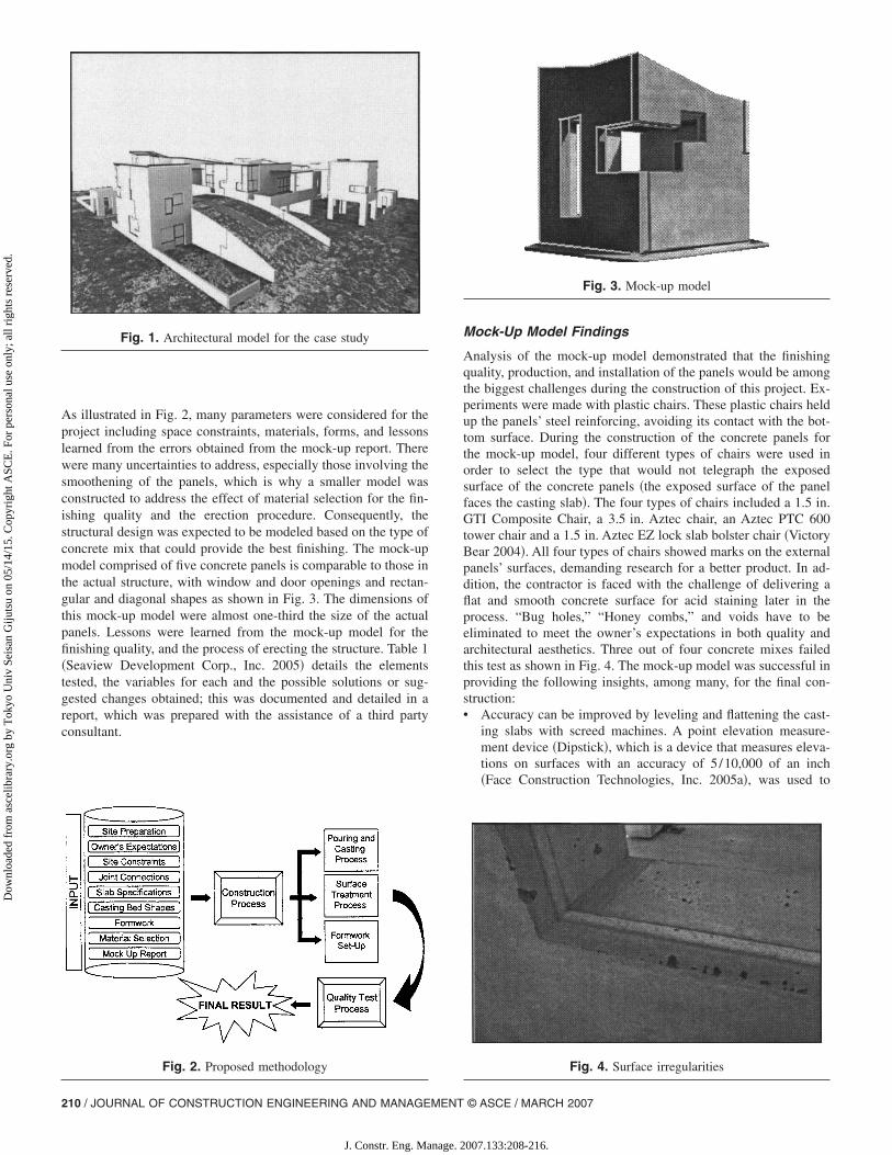
As illustrated in Fig. 2, many parameters were considered for theproject including space constraints, materials, forms, and lessonslearned from the errors obtained from the mock-up report. Therewere many uncertainties to address, especially those involving thesmoothening of the panels, which is why a smaller model wasconstructed to address the effect of material selection for the fin-ishing quality and the erection procedure. Consequently, thestructural design was expected to be modeled based on the type ofconcrete mix that could provide the best finishing. The mock-upmodel comprised of five concrete panels is comparable to those inthe actual structure, with window and door openings and rectan-gular and diagonal shapes as shown in Fig. 3. The dimensions ofthis mock-up model were almost one-third the size of the actualpanels. Lessons were learned from the mock-up model for thefinishing quality, and the process of erecting the structure. Table 1�Seaview Development Corp., Inc. 2005� details the elementstested, the variables for each and the possible solutions or sug-gested changes obtained; this was documented and detailed in areport, which was prepared with the assistance of a third partyconsultant.
Fig. 1. Architectural model for the case study
Fig. 2. Proposed methodology
210 / JOURNAL OF CONSTRUCTION ENGINEERING AND MANAGEMENT
J. Constr. Eng. Manage. 2
Mock-Up Model Findings
Analysis of the mock-up model demonstrated that the finishingquality, production, and installation of the panels would be amongthe biggest challenges during the construction of this project. Ex-periments were made with plastic chairs. These plastic chairs heldup the panels’ steel reinforcing, avoiding its contact with the bot-tom surface. During the construction of the concrete panels forthe mock-up model, four different types of chairs were used inorder to select the type that would not telegraph the exposedsurface of the concrete panels �the exposed surface of the panelfaces the casting slab�. The four types of chairs included a 1.5 in.GTI Composite Chair, a 3.5 in. Aztec chair, an Aztec PTC 600tower chair and a 1.5 in. Aztec EZ lock slab bolster chair �VictoryBear 2004�. All four types of chairs showed marks on the externalpanels’ surfaces, demanding research for a better product. In ad-dition, the contractor is faced with the challenge of delivering aflat and smooth concrete surface for acid staining later in theprocess. “Bug holes,” “Honey combs,” and voids have to beeliminated to meet the owner’s expectations in both quality andarchitectural aesthetics. Three out of four concrete mixes failedthis test as shown in Fig. 4. The mock-up model was successful inproviding the following insights, among many, for the final con-struction:• Accuracy can be improved by leveling and flattening the cast-
ing slabs with screed machines. A point elevation measure-ment device �Dipstick�, which is a device that measures eleva-tions on surfaces with an accuracy of 5/10,000 of an inch�Face Construction Technologies, Inc. 2005a�, was used to
Fig. 3. Mock-up model
Fig. 4. Surface irregularities
© ASCE / MARCH 2007
007.133:208-216.

Dow
nloa
ded
from
asc
elib
rary
.org
by
Tok
yo U
niv
Seis
an G
ijuts
u on
05/
14/1
5. C
opyr
ight
ASC
E. F
or p
erso
nal u
se o
nly;
all
righ
ts r
eser
ved.
check the F-numbers �which will be described in detail later inthis paper�. One of the casting slabs used in the mock-upmodel was tested, producing a FL of 10.83. With this unsatis-factory level of accuracy, the concrete panels barely fit to-gether. F-numbers ranging in values of 55–65 and 45–50 �forfloor flatness �FF� and floor levelness �FL�, respectively� weresuggested for the actual construction �the calculations of thesenumbers will be described later in this paper�. Casting overjoint controls was also not accepted, since they left visiblemarks on the panel surfaces.
• Shape precision for the concrete panels can be improved bycutting the formwork on-site �Table 1�. Tolerance guidelines,as listed in Table 2, were determined to be used for the actualconstruction.
• A concrete mix with plasticizer, self-leveled and self-compacted must be used in order to reduce bug holes andcracks as shown in Fig. 4.
• A curing compound is necessary to enhance the finishing qual-ity �Table 1�. A double-silicon seal coat should be applied toseparate the casting slabs from the panels.
Case Study
The facility used for the case study is a unique private facility inNew York that has been in construction since June 2004. De-signed by Steven Holl �Holl 2004�, this facility uses a construc-tion methodology based on tilt-up panels, which uses reinforcedconcrete panels that are cast on-site and then lifted with a crane.With more than 22,000 squared feet in footprint area, this facilitycomprises four pavilions and includes a library, garden house,gallery, sport, and entertainment facilities. This complex projectincludes 108 tilt-up panels as shown in Fig. 5, and is unique in
Table 2. Tolerances for Tilt-Up Panels �Seaview Development Corp., In
Feature
Height and width up to 30 ft
Each additional 10 ft increment over 30 ft
Thickness of panels
Squareness of panels as measured on two diagonals
Size and location of openings cast into panels
Location of embedded connection
Reinforcing steel cover
Seam width between panels
Offset at face of adjoining panels
Fig. 5. Types of panel-to-panel connections
JOURNAL OF CONSTRUCTION
J. Constr. Eng. Manage. 2
terms of the jigsaw-like shapes, all of which have different sizesand weights as shown in Fig. 6. Many of these panels exceeded10�10 m �35�35 ft� and weighed from 1,356 kg �3,000 lb� to27,572 kg �61,000 lb�. Most of the panels have a thickness of20 cm �8 in.�; but some are 27.94 cm �11 in.�. As shown in Fig.6, each panel is unlike the other, presenting challenges to inter-locking them as one unit. The architectural requirements of theproject necessitated the use of a tilt-up construction method dueto the quality surface and smooth finish that can be transferredfrom the casting slabs to the concrete panels. Since the panels areexposed to the outdoors, the smoothness of the surface plays animportant role in the development of this construction. Anotherimportant feature of this facility is the interlocking precision re-lated to the panel assembly. As was previously mentioned,1.27 cm �0.5 in.� joints separate the ends of the panels from eachother, increasing the difficulty of the construction and installationprocess �Fig. 5�. Some of the panels interlock on the same plane,while others interlock at 90° in corners and as a consequence,have their end sides exposed. The end sides of the panels were notin contact with the casting slabs, but they were in contact with theforms. Polystyrene form liners were used to provide smooth sidesurfaces and rounded corners. The advantage of using form linersis that they provide a more even surface than the casting slabsthemselves. For windows and doors, tapered radius corners werenot used due to future window/door frame installations.
Construction Process
Due to space constraints, a short time for the erection process,high equipment costs �crane rental costs�, the site layout, and thelocation of the cast panels on the casting slabs needed to be assimple as possible to minimize the constraints for the lifting pro-
4��
Min Max
−1/8 in. �−0.317 cm� +0
1/16 in. �−0.158 cm� +0
−1/8 in. �−0.371 cm� +0
−1/4 in. �−0.635 cm� +0
1/16 in. �−0.158 cm� +1/16 in. �+0.158 cm�−1/8 in. �−0.317 cm� +1/8 in. �+0.317 cm�−1/4 in. �−0.635 cm� +1/4 in. �+0.635 cm�1/16 in. �−0.158 cm� +0
1/16 in. �−0.158 cm� +1/16 in. �+0.158 cm�
Fig. 6. 108 concrete panels used for the case study
c. �200
−
−
−
−
ENGINEERING AND MANAGEMENT © ASCE / MARCH 2007 / 211
007.133:208-216.

Dow
nloa
ded
from
asc
elib
rary
.org
by
Tok
yo U
niv
Seis
an G
ijuts
u on
05/
14/1
5. C
opyr
ight
ASC
E. F
or p
erso
nal u
se o
nly;
all
righ
ts r
eser
ved.
cess. The construction process required an adequate capacitycrane for panel installation. The strategy was to rent a technicallyfeasible and most cost effective crane; a crawler crane was se-lected for this purpose �Manitowoc 888,230 t�, �Manrique et al.2005�. The final layout with the concrete panels’ locations on thecasting slabs was the key in enhancing the installation process�Fig. 7�; this process is fully described in the companion paper,“Constructing a Complex Tilt-Up-Panel Structure Utilizing anOptimization Model, 3D CAD, and Animation.” The numbers onFig. 7 represent the crane picking/lifting relocation points for thedifferent subgroups of panels.
The complex nature of this project posed a challenge to opti-mize the construction process. Erecting tilt-up panels is not awidely used technique for residential construction, especially forbuildings with panels that have irregular shapes. The formworkutilized for the construction of the panels is not reusable, as eachpanel is completely different. The panels must also be poured inshort succession for quality purposes �to ensure that the mixwould be the same in a large set of panels with the same textureand aggregate color�. Evaluating the constraints before tilting upeach panel not only reduced cost, time, and labor, but the instal-lation was made safely and provided an acceptable tolerancelevel. Several layouts with different casting slab shapes and dif-ferent panel locations were proposed and experimented with dur-ing the planning stage. The selected casting slabs were placedaround the facility, allowing the crane to move between the houseand the cast panels. The path of the crane �dotted line in Fig. 7�,had a width of 14 m �46 ft�. To avoid cracks and fissures, thegeotechnical engineer required that the crane, should keep a mini-mum distance of 3.65 m or 12 ft from the foundation walls. Oneof the main reasons for leaving such a distance between the craneand the structure was the weight pressure that would be exertedby the crane against the footing and the basement walls. Thecasting slab sizes range from 12.80�12.80 m �42�42 ft� to15.84�15.84 m �52�52 ft�. The total casting slab area was4,316 m2 �46,458 ft2�. Layouts were arranged according to spaceconstraints, which maintained square shapes to avoid concretecracks.
The site was graded with a bulldozer and a 15.24 cm �6 in.�stone base layer was place to avoid future settlement. A rollingvibrator was used to compact the layer until it reached 95% com-paction. This compaction percentage was obtained based on thepermeability test using the maximum dry density of the material.
Fig. 7. Construction layout
If the material is compacted at a higher rate or lower rate, it will
212 / JOURNAL OF CONSTRUCTION ENGINEERING AND MANAGEMENT
J. Constr. Eng. Manage. 2
expand or shrink and damage the casting slab. The minimum jointseparations between casting slabs was set at 2.54 cm �1 in.�, thejoint separations were placed to create rectangular shapes; someof the casting slabs did not match the previously defined panellayout specifications, but ultimately the ratio between width andheight was never less than 0.94. The minimum acceptable sepa-ration between the panel forms was set at 20.32 cm �8 in.� toallow for tilt-up.
Construction of Casting Slabs
The casting slabs used a 3,500 psi concrete mix and did not re-quire reinforcing due to their thickness �10 cm or 4 in.� and timeof pouring �in spring�. A laser screed machine with a 3.65 m�12 ft� arm flattened and leveled the concrete. While the concretewas poured, the laser screed machine ensured the flatness andlevelness of the slab. An automatic laser control system providedan accurate finishing through the use of electrohydraulic controls.Recently, a wide variety of concrete curing and finishing productshave become available for construction projects. In this casestudy, the bond breaker �Nox-Crete 2003� was the product used tocure, seal and harden the casting slabs based on the results and theguidelines obtained from the mock-up model. The bond breakerfulfilled the construction requirements in terms of quality finish-ing, concrete bonding and suitability for the ambient temperatureconditions during the casting process. This product allows con-structors to improve the smoothness and hardness of concretesurfaces, and it also allows the separation between two concretesurfaces. Since the smoothness factor played such an importantrole for panel surface finishing; eliminating the porosity and thevoids on the casting slabs allowed for the quality expectations tobecome somewhat achievable. The treatment process began oncethe casting slabs had solidified. After preparing the chemical mix,the operator sprayed the solution over the slabs. For quality as-surance purposes, the casting slabs were sprayed with the bondbreaker within a 30 min window. Areas that had dried in theelapsed time period had to be sprayed again to provide a homo-geneous result.
Next, the puddles were swept away to create a uniform effecton the casting slabs. Water was then hosed over the surface tohelp the chemical solution penetrate into the concrete surface. Atthe same time, the residue was removed with a broom to avoidstains. The casting slabs were poured during spring and to obtaina high-quality finish on the interior faces of the panels, it wasnecessary to apply three coats of the bond braking compound.The first one was used to cure the concrete slabs, and the secondand third coats were required to facilitate the separation of theconcrete panels from the casting slabs �Nox-Crete 2004�. Thebond breaker requires less water during cold weather conditionswhich is a primary consideration in the curing process. To guar-antee quality, the bond breaker exceeded the moisture retentionrequirements by ASTM as indicated in the reference. However,the chemical solution did not work as it was intended becausesome surface flaws were discovered after tilting up the panels.This is explained in detail later in the section “EncounteredErrors.”
Formwork Setup
After testing the flatness and levelness of the casting slabs, thepanels were outlined with chalk. The rule of 3-4-5 was used totrace squared angles. By tracing two perpendicular lines from the
same origin with 3 and 4 m �or ft�, the length measure from their© ASCE / MARCH 2007
007.133:208-216.
Dow
nloa
ded
from
asc
elib
rary
.org
by
Tok
yo U
niv
Seis
an G
ijuts
u on
05/
14/1
5. C
opyr
ight
ASC
E. F
or p
erso
nal u
se o
nly;
all
righ
ts r
eser
ved.
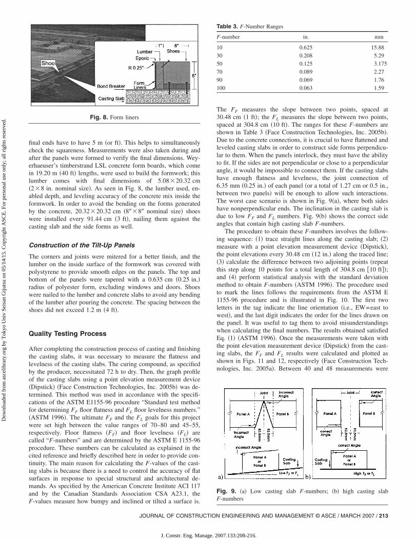
final ends have to have 5 m �or ft�. This helps to simultaneouslycheck the squareness. Measurements were also taken during andafter the panels were formed to verify the final dimensions. Wey-erhaeuser’s timberstrand LSL concrete form boards, which comein 19.20 m �40 ft� lengths, were used to build the formwork; thislumber comes with final dimensions of 5.08�20.32 cm�2�8 in. nominal size�. As seen in Fig. 8, the lumber used, en-abled depth, and leveling accuracy of the concrete mix inside theformwork. In order to avoid the bending on the forms generatedby the concrete, 20.32�20.32 cm �8��8� nominal size� shoeswere installed every 91.44 cm �3 ft�, nailing them against thecasting slab and the side forms as well.
Construction of the Tilt-Up Panels
The corners and joints were mitered for a better finish, and thelumber on the inside surface of the formwork was covered withpolystyrene to provide smooth edges on the panels. The top andbottom of the panels were tapered with a 0.635 cm �0.25 in.�radius of polyester form, excluding windows and doors. Shoeswere nailed to the lumber and concrete slabs to avoid any bendingof the lumber after pouring the concrete. The spacing between theshoes did not exceed 1.2 m �4 ft�.
Quality Testing Process
After completing the construction process of casting and finishingthe casting slabs, it was necessary to measure the flatness andlevelness of the casting slabs. The curing compound, as specifiedby the producer, necessitated 72 h to dry. Then, the graph profileof the casting slabs using a point elevation measurement device�Dipstick� �Face Construction Technologies, Inc. 2005b� was de-termined. This method was used in accordance with the specifi-cations of the ASTM E1155-96 procedure “Standard test methodfor determining FF floor flatness and FL floor levelness numbers.”�ASTM 1996�. The ultimate FF and the FL goals for this projectwere set high between the value ranges of 70–80 and 45–55,respectively. Floor flatness �FF� and floor levelness �FL� arecalled “F-numbers” and are determined by the ASTM E 1155-96procedure. These numbers can be calculated as explained in thecited reference and briefly described here in order to provide con-tinuity. The main reason for calculating the F-values of the cast-ing slabs is because there is a need to control the accuracy of flatsurfaces in response to special structural and architectural de-mands. As specified by the American Concrete Institute ACI 117and by the Canadian Standards Association CSA A23.1, the
Fig. 8. Form liners
F-values measure how bumpy and inclined or tilted a surface is.
JOURNAL OF CONSTRUCTION
J. Constr. Eng. Manage. 2
The FF measures the slope between two points, spaced at30.48 cm �1 ft�; the FL measures the slope between two points,spaced at 304.8 cm �10 ft�. The ranges for these F-numbers areshown in Table 3 �Face Construction Technologies, Inc. 2005b�.Due to the concrete connections, it is crucial to have flattened andleveled casting slabs in order to construct side forms perpendicu-lar to them. When the panels interlock, they must have the abilityto fit. If the sides are not perpendicular or close to a perpendicularangle, it would be impossible to connect them. If the casting slabshave enough flatness and levelness, the joint connection of6.35 mm �0.25 in.� of each panel �or a total of 1.27 cm or 0.5 in.,between two panels� will be enough to allow such interactions.The worst case scenario is shown in Fig. 9�a�, where both sideshave nonperpendicular ends. The inclination in the casting slab isdue to low FF and FL numbers. Fig. 9�b� shows the correct sideangles that contain high casting slab F-numbers.
The procedure to obtain these F-numbers involves the follow-ing sequence: �1� trace straight lines along the casting slab; �2�measure with a point elevation measurement device �Dipstick�,the point elevations every 30.48 cm �12 in.� along the traced line;�3� calculate the difference between two adjoining points �repeatthis step along 10 points for a total length of 304.8 cm �10 ft��;and �4� perform statistical analysis with the standard deviationmethod to obtain F-numbers �ASTM 1996�. The procedure usedto mark the lines follows the requirements from the ASTM E1155-96 procedure and is illustrated in Fig. 10. The first twoletters in the tag indicate the line orientation �i.e., EW=east towest�, and the last digit indicates the order for the lines drawn onthe panel. It was useful to tag them to avoid misunderstandingswhen calculating the final numbers. The results obtained satisfiedEq. �1� �ASTM 1996�. Once the measurements were taken withthe point elevation measurement device �Dipstick� from the cast-ing slabs, the FF and FL results were calculated and plotted asshown in Figs. 11 and 12, respectively �Face Construction Tech-nologies, Inc. 2005a�. Between 40 and 48 measurements were
Table 3. F-Number Ranges
F-number in. mm
10 0.625 15.88
30 0.208 5.29
50 0.125 3.175
70 0.089 2.27
90 0.069 1.76
100 0.063 1.59
Fig. 9. �a� Low casting slab F-numbers; �b� high casting slabF-numbers
ENGINEERING AND MANAGEMENT © ASCE / MARCH 2007 / 213
007.133:208-216.

Dow
nloa
ded
from
asc
elib
rary
.org
by
Tok
yo U
niv
Seis
an G
ijuts
u on
05/
14/1
5. C
opyr
ight
ASC
E. F
or p
erso
nal u
se o
nly;
all
righ
ts r
eser
ved.
taken along the traced lines on each section of the casting slabs.The procedure stated in the ASTM E 1155-96 was used to calcu-late the average of the F-numbers
FF1+2= FF1
· FF2� rq1
+ rq2
rq2· FF1
2 + rq1· FF2
2 �1�
where FFi=floor flatness; and rqi=number of measurements.The composite results for the casting slabs are shown in Table
4, where each result is compounded with the next adjacent section�in this case, six sections�, producing final values of 56.39 and44.31 for the FF and FL numbers, respectively. The expected highnumbers of FF=75 and FL=50 were not accomplished, but theresults were within the acceptable range of quality. A low FF
value means that the surface of the casting slabs would haveirregular bumps or dips. An FF accuracy of 56.39 implies that thecasting slab surface had a height difference of 2.8 mm in304.8 cm �approximately 1/9 in. in 10 ft�. As shown in Fig. 9�a�,this height difference between two points will produce an incli-nation on the casting slab. For the FL, the casting slab had aninclination of 3.58 mm in 304.8 cm �approximately 1/7 in. in
Fig. 10. Floor flatness and floor levelness, Section 1
Fig. 11. Floor flatness results
214 / JOURNAL OF CONSTRUCTION ENGINEERING AND MANAGEMENT
J. Constr. Eng. Manage. 2
10 ft�. Using the maximum panel length of 10.67 m �35 ft�, themaximum dips or bump that would be obtained is 9.8 mm for theFF and 12.53 mm for the FL. The inclination angle obtained withthese two values is not higher than 5.3�10−2°.
Now using a concrete panel thickness of 203.2 mm �8 in.�, themaximum side opening will be 1.86�10−1 mm. This value doesnot represent more than 3% of the maximum joint panel require-ment �6.35 mm or 1/4 in.� as shown in Fig. 9�a�. The F-numbersof 75/50 �for FF and FL, respectively� were not required for thestructural design as explained before, but were obtained for aes-thetic purposes. The FF has to be higher that the FL since it iscalculated on a shorter distance �30.48 cm or 1 ft�; if it is lower,the surface will have more dips and bumps. An assumption wasmade that the side of the panel facing the casting slab will havethe same FF and FL. The F-numbers were not calculated on theconcrete panels’ top surface, which is the interior face; any incli-nation on the internal face of the panel does not affect the struc-ture. The approach for the construction was to cast the concretepanels outdoors. Due to the following:1. Doing the work in a controlled environment could increase
the F-numbers, but only by a small margin, at a higher cost.Due in part to the shear-size of about 20-panels; transporta-tion of these panels could have been possible. It could be ata very high cost of delivery that would include relocatingpower lines and other abstractions in the road. The concretepanels were as wide as 10.70 m �35 ft�.
2. The expected increase of the F-numbers would not justifythe high cost and would not add marginal value to the endproduct as described before.
3. Unless the panels are cast on steal sheets, the reusability ofconcrete slabs could cause imperfection after the first use.Therefore, a casting slab with sufficient size that allows forall the panels to be cast was a preferred option. This optionwould not be acceptable by any manufacturer. The imperfec-
Table 4. Composite F-Number Results
Composition FF FL
Sections 1 and 2 53.5 41.54
Previous and Section 3 52.06 42.83
Previous and Section 4 54.82 42.34
Previous and Section 5 55.30 43.42
Previous and Section 6 56.39 44.31
Fig. 12. Floor levelness results
© ASCE / MARCH 2007
007.133:208-216.
Dow
nloa
ded
from
asc
elib
rary
.org
by
Tok
yo U
niv
Seis
an G
ijuts
u on
05/
14/1
5. C
opyr
ight
ASC
E. F
or p
erso
nal u
se o
nly;
all
righ
ts r
eser
ved.
tions obtained by casting the concrete panels on-site are at-tributed to the methods used for their construction such as:the laser-skid limitations, the environment, and the concreteshrinkage.
For the panels’ layout on the casting slabs, measurements wererepeated three times to verify the correct dimensions of eachpanel. The forms were measured several times in different daysfrom their inside surface, to ensure that the perpendicular anglesbetween the floor and the lumber were not changing over time.After the panels were verified, the next step was to install thereinforcing and rebar required for the structure, including chairs,weld plates, lifting hardware �such as hooks and lifting points�,and electrical ducts. Due to the constant rainfall, each finishedform was covered with a plastic layer to avoid puddles and dirt.From this process, the team discovered that it is better to coverthe forms using a sloped plastic layer rather than a flat one inorder to shed the panel from water. It was impossible to com-pletely avoid the deposition of moisture and dirt on the forms,making it necessary to clean them periodically to neutralize fun-gus and remove excess mud. The following difficulties were en-countered during the cleaning process: Some panels requiredmore steel reinforcement, which left small gaps between the bars,interfering with the reach of the cleaners to the casting slabs. Aircompressors were used with lower air pressure in order to avoiddamage to the surface and removal of the bond breaker.
Encountered Errors
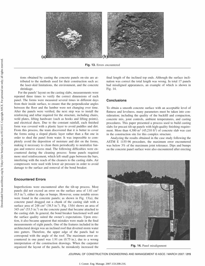
Imperfections were encountered after the tilt-up process. Mostpanels did not exceed an error on the surface area of 1.61 cm2
�0.5 in.2�, either in dips or bumps. However, some notable errorswere found in the concrete panels; as shown in Fig. 13�a�, theconcrete panel dragged out a chunk of the casting slab with asurface area of 248 cm2 �38.5 in.2�. Fig. 13�b� shows an area of345 cm2 �53.5 in.2� on the concrete panel that became attached tothe casting slab. In general, the bond breaker functioned well andthe surface quality suited the owner’s expectations. Upon erec-tion, it also became apparent that mistakes were made in the finalmeasurements of eight panels. One of the features included in thearchitectural design was an inclined roof that diverted storm waterinto gutters. Therefore, the upper edge of the panels had tocorrespond with the angle of the roof. The maximum error en-countered in one panel was 1.91 cm �0.75 in.�, due to a wronginterpretation of the construction drawings. When the carpenter
Fig. 13. Er
organized the layout of the panels, he mistakenly increased the
JOURNAL OF CONSTRUCTION
J. Constr. Eng. Manage. 2
final length of the inclined top ends. Although the surface incli-nation was correct the total length was wrong. In total 17 panelshad misaligned appearances, an example of which is shown inFig. 14.
Conclusions
To obtain a smooth concrete surface with an acceptable level offlatness and levelness, many parameters must be taken into con-sideration; including the quality of the backfill and compaction,concrete mix, joint controls, ambient temperatures, and castingprocedures. This paper presented a process used to build castingslabs for precast tilt-up panels with high-quality finishing require-ment. More than 4,300 m2 �45,210 ft2� of concrete slab was castin the construction site for this complex structure.
Analyzing the results obtained in the case study following theASTM E 1155-96 procedure, the maximum error encounteredwas below 3% of the maximum joint tolerance. Dips and bumpson the concrete panel surface were also encountered after erecting
ncountered
Fig. 14. Panel misalignment
rors e
ENGINEERING AND MANAGEMENT © ASCE / MARCH 2007 / 215
007.133:208-216.

Dow
nloa
ded
from
asc
elib
rary
.org
by
Tok
yo U
niv
Seis
an G
ijuts
u on
05/
14/1
5. C
opyr
ight
ASC
E. F
or p
erso
nal u
se o
nly;
all
righ
ts r
eser
ved.
the panels. This problem was possibly related to the difficulty ofcleaning the casting slabs before the concrete was poured for thepanels. Other reasons for this failure include a lack in efficiencyof the bond breaker, or an even distribution of bond breaker onthe surface. Even though compressed air was used to clean thedirt in the forms, the high amount of reinforcing made it impos-sible to reach, clean and spray some of the inner areas on thebottom of the panels.
All the procedures applied in the construction and installationof the formwork was conducted in accordance with the structuralengineer’s specifications, but mistakes were still made in the cast-ing of the panels with an inclined upper edge. Fortunately, thesemistakes will be covered by the roof. This project was noteworthysince it applied the precision-focused methods of commercialbuilding construction on a residential scale. It is not common forflatness and levelness to be so crucial in the making of castingslabs. In this case, these factors were imperative for flush inter-locking of the rectangular edges of the panels. A small deviationfrom perpendicularity would manifest itself in a noticeable imper-fection at the junctions between panels.
In addition to structural prerogatives, this project also necessi-tated smooth surfaces on the concrete panels to facilitate thearchitect’s vision of a uniform exposed surface. Based on theanalysis results from this construction process, developers canincorporate precision planning concerning materials selection andmanagement into future constructions. The success of this projectreinforced many beliefs that the level of quality required by theowner/architect was impossible to achieve. Lessons learned anddocumented in this paper are of value for future project develop-ments.
Acknowledgments
The information gathered and presented in this document is de-rived from the good practice of engineering and a commitment toimprove and enhance a process that satisfied the owner’s desirefor excellent results. Special thanks to the Seaview DevelopmentCorportation team for providing the opportunity and the means toperform this research, for their help and unconditional support.
Notation
The following symbols are used in this paper:F � floor flatness;
F216 / JOURNAL OF CONSTRUCTION ENGINEERING AND MANAGEMENT
J. Constr. Eng. Manage. 2
FL � floor levelness; andrq � number of measurements.
References
ASTM. �1996�. “Standard test method for determining FF floor flatnessand FL floor levelness numbers.” ASTM E 1155-96. West Consho-hocken, Pa. 1–8.
Canadian Precast Prestressed Concrete Institute �CPCI�. �2003�. “Benefitsand advantages.” �http://www.cpci.ca� �March 17, 2006�.
Chithanranjan, N. �1998�. “A housing kit for mass housing.” Indian Con-crete J., 72�1�, 41–46.
Face Construction Technologies, Inc. �2005a�. “Dipstick elevation stud-ies.” The Dipstick, Norfolk, Va., 1–6.
Face Construction Technologies, Inc. �2005b�. “Dipstick hints and tips—DS2272 version.” The Dipstick, Norfolk, Va., 1–4.
Future Tech Consultants of New York, Inc. �FTC�. �2005�. “Floor flatnessand levelness survey.” �http://www.ftcny.com� �Jan. 5, 2006�.
Hanna, A., and Zenon, Z. �2003�. “Prefabricated concrete foundations forhousing.” Int. J. Housing Science, 27�1�, 41–51.
Holl, S. �2004�. Steven Holl Architecs, Brooklyn, N.Y., �http://www.stevenholl.com/� �December 10, 2005�.
Manrique, J., Al-Hussein, M., Telyas, A., and Funston, G. �2005�. “Con-structing a unique and complex tilt-up-panel structure utilizing 3DCAD and animation.” 22nd Int. Symp. on Automation and Robotics inConstruction—Program and Abstracts, Ferrara, Italy, 98.
Meadow Burk. �2002�. Meadow Burke on tilt-up: The complete tilt-upsystem manual, Meadow Burke Products, Tampa, Fla., 5–81.
Mehta, P. K., and Monteiro, P. J. M. �1993�. Concrete structure, proper-ties, and materials, 2nd Ed., Prentice-Hall, Englwood Cliffs, N.J.
National Geographic Society. �2002�. “Megastructures: Petronas Tow-ers.” Prime time videos, �www.nationalgeographic.com� �October 4,2005�.
Nox-Crete Products Group. �2003�. “Chemical solutions to concreteproblems.” Product data and specifications, Omaha, Neb., 1–8.
Nox-Crete Products Group. �2004�. “Single source solutions for tilt-upconstruction.” Product data and specifications, Omaha, Neb., 3–11.
Seaview Development Corp., Inc. �2004�. “68 Wheatley mock-up panelsinstallation and fabrication.” �www.seaviewcorp.com� �Sepemtber 15,2005�.
Stephens, J. �1976�. Towers, bridges, and other structures. Sterling, NewYork, 116–141.
Victory Bear. �2004�. “Construction products for pre-cast concrete andtilt-up constructions.” �http://www.victorybear.com� �September 22,2005�.
Weimann, M. �2004�. “Application of laser light for the fabrication ofconcrete assembly units.” �www.z-laser.com� �March 2006�.
West, M., Court, S., Melo, J., Thomas, D., Vivas, W., Wiebe, C., andWittman, D. �2002�. “Concrete wall panels.” Materials TechnologyWorkshop, Dept. of Architecture, Univ. of Manitoba.
© ASCE / MARCH 2007
007.133:208-216.

本文献由“学霸图书馆-文献云下载”收集自网络,仅供学习交流使用。
学霸图书馆(www.xuebalib.com)是一个“整合众多图书馆数据库资源,
提供一站式文献检索和下载服务”的24 小时在线不限IP
图书馆。
图书馆致力于便利、促进学习与科研,提供最强文献下载服务。
图书馆导航:
图书馆首页 文献云下载 图书馆入口 外文数据库大全 疑难文献辅助工具