
CASE F! LE COPY
90
CH ME MORAND NASA TM X-2779 CASE F! LE COPY I-% LAT-BYPASS BLEED SYSTEMS FOR __REASING THE STABLE AIRFLOW RANGE MACH 2.50 AXISYMMETRIC INLET 40-PERCENT INTERNAL CONTRACTION _ ,y w S..aers rch Center Ohio ONAUTICS 44135 and Glenn A. Mitchell AND S_E-ADMINiSTRATtON • WASHINGTON,D. C. • MAY 1973 https://ntrs.nasa.gov/search.jsp?R=19730014220 2020-03-23T05:12:49+00:00Z
Transcript of CASE F! LE COPY

CH
ME MORAND
NASA TM X-2779
CASE F! LECOPY
I-%LAT-BYPASS BLEED SYSTEMS FOR
__REASING THE STABLE AIRFLOW RANGE
MACH 2.50 AXISYMMETRIC INLET
40-PERCENT INTERNAL CONTRACTION
_ ,y w S..aersrch Center
OhioONAUTICS
44135
and Glenn A. Mitchell
AND S_E-ADMINiSTRATtON • WASHINGTON,D. C. • MAY 1973
https://ntrs.nasa.gov/search.jsp?R=19730014220 2020-03-23T05:12:49+00:00Z

..... i ..... . ...........
7 ....

1. Report No, 2. Government Accession No.
NASA TM X-2779
4. Title and Subtitle
THROAT-BYPASS BLEED SYSTEMS FOR INCREASING THE
STABLE AIRFLOW RANGE OF A MACH 2.50 AXISYMMETRIC
INLET WITH 40-PERCENT INTERNAL CONTRACTION
7. Author(s)
Bobby W. Sanders and Glenn A. Mitchell
9. Performing Organization Name and Address
Lewis Research Center
National Aeronautics and Space Administration
Cleveland, Ohio 44135
12. Sponsoring Agency Name and Address
National Aeronautics and Space Administration
Washington, D.C. 20546
3. Recipient's Catalog No.
5. Report Date
May 1973
6. Performing Organization Code
8. Performing Organization Report No.
E-7240
10. Work Unit No.
501-24
11. Contract or Grant No.
13. Type of Report and Period Covered
Technical Memorandum
14, Sponsoring Agency Code
15. Supplementary Notes
16. Abstract
The results of an experimental investigation to increase the stable airflow range of a super-
sonic mixed-compression inlet are presented. Various throat-bypass bleeds were located
on the inlet cowl. The bleed types were distributed porous normal holes, a forward-slanted
slot, or distributed educated slots. Large inlet stability margins were obtained with the in-
let throat bleed systems if a constant pressure was maintained in the throat-bypass bleed
plenum. Stability limits were determined for steady-state and limited transient internal air_
flow changes. Limited unstart angle-of-attack data are presented.
17. Key Words (Suggested by Author(s}}
Air intakes; Supersonic-cruise inlets; Shock
stability; Inlet bleed; Throat-bypass bleed
18. Distribution Statement
Unclassified - unlimited
19. Security Classif. (of this report)
Unclassified
20. Security Classif. (of this page) 21. No. of Pages 22. Price*
Unclassified 8 7 $3.00
* For sale by the Nationat Technical Information Service, Springfield, Virginia 22151


THROAT-BYPASS BLEEDSYSTEMS FOR INCREASINGTHE STABLE
AIRFLOW RANGE OFA MACH 2.50AXISYMMETRIC INLET
WITH 40-PERCENTINTERNALCONTRACTION
byBobbyW. Sandersand GlennA. Mitchell
LewisResearchCenter
SUMMARY
An experimental investigation was conducted to evaluate the effectiveness of various
types of inlet throat-bypass bleed in providing an increased inlet stable airflow range.
The inlet used in the investigation was an axisymmetric, bicone, mixed-compression
type with 40 percent of the supersonic area contraction occurring internally at the design
Mach number of 2.50. Data were obtained at this design Mach number for distributed
porous, forward-slanted-slot, and distributed educated-slot bleed types. A porous
boundary-layer bleed arrangement was located on the centerbody in order to achieve high
performance during normal operation.
With the inlet operating at a high-performance condition, each of the throat-bypass
bleed types provided a large stability range prior to inlet unstart. In terms of inlet
diffuser-exit-corrected airflow, each of the bleed types provided a reduction in corrected
airflow prior to unstart (stability range) of 20 percent or greater ff a constant pressure
was maintained in the stability bleed plenum from the initial condition to inlet unstart.
Unstart angle-of-attack tolerance for most of the bleed configurations tested was equal to
or greater than 4.5 °. The maximum unstart angle-of-attack obtained was 7.6 °. Data
show that the angle-of-attack tolerance of the inlet was increased by locating all center-
body bleed upstream of the throat and distributing the cowl bleed over a large axial length
in the inlet throat region.
INTRODUCTION
The function of a supersonic inlet is to supply the airflow required by an engine at
the highest possible pressure level while maintaining minimum drag. To minimize inlet
cowl drag for sustained flight at speeds above Mach 2.0, it becomes essential that some

portion of the supersonic area contraction be accomplished internally. An inlet of this
type is commonly referred to as a mixed-compression inlet. For mixed-compression
inlets, optimum internal performance is provided by maintaining the terminal shock at
the inlet throat. This operation provides high pressure recovery and minimizes distor-
tion at the engine face. These inlets, however, have a discontinuous airflow character-
istic known as unstart. If an airflow transient causes the terminal shock to move up-
stream of the throat, the shock is unstable and is abruptly expelled ahead of the cowling.
This shock expulsion or unstart causes a sharp reduction in mass flow and pressure re-
covery and a large drag increase. Inlet buzz, compressor stall, and/or combustor blow-
out may also occur. Obviously, an inlet unstart is extremely undesirable because of the
adverse effects not only on the propulsion system itself, but also on the aerodynamic
qualities of the aircraft. If inlet unstart does occur, complex mechanical variations to
alter the inlet geometry are required to re-establish initial design operating conditions.
Both external airflow transients such as atmospheric turbulence and internal airflow
changes such as a reduction in engine airflow demand can cause the inlet to unstart. For
an internal airflow change, the inlet should provide a margin in corrected airflow below
the value for optimum performance without incurring unstart. This margin is defined as
the stable airflow range. Conventional mixed-compression inlets may be designed to
have a limited stable range that is provided by the capacity of the performance bleed sys-
tem to spill increased airflow as the terminal shock moves upstream in the throat region.
With performance bleed exit areas that are fixed, this stable range may not be adequate
to absorb many of the airflow transients that are encountered by a supersonic propulsion
system. An increased stable airflow range is currently provided for these inlets by op-
erating them supercritically with a resultant loss in performance. Since any loss in inlet
efficiency is reflected directly as a loss in thrust of the propulsion system, supercritical
operation is undesirable.
To provide the necessary inlet stability without compromising steady-state perform-
ance, the inlet can be designed to allow the throat bleed to function as a throat bypass.
This system prevents unstart by allowing the throat bleed to compensate naturally for
changes in diffuser exit airflow demand. References 1 and 2 have shown that large in-
creases in bleed may be provided as the inlet operation proceeds from supercritical to
minimum stable conditions, without prohibitive amounts of bleed during normal operation,
if the bleed exit area can be controlled to maintain a near-constant pressure in the throat-
bypass bleed plenum. This exit-area variation might be provided either by an active con-
trol that senses shock position and regulates the bleed exit area or by high-speed valves
that react to bleed plenum pressure changes that occur when the terminal shock changes
position. Experimental results that are presented in references 2 and 3 show that high-
speed valves can operate automatically to provide large stable margins.
An inlet test program was undertaken in the Lewis 10- by 10-Foot Supersonic Wind
Tunnel to evaluate the effectiveness of several different types of such stability bleed

systems. This investigation was conducted with a Mach 2.5 mixed-compression inlet
having 40 percent of the design supersonic area contraction occurring internally. Throat-
bypass bleed airflow was removed through either distributed porous holes, distributed
educated slots, or a forward-slanted slot. The open cowl bleed areas were designed to
remove approximately 20 percent of the inlet capture airflow during minimum stable op-
eration if a near-constant bleed plenum pressure was maintained.
Some selected results of this test program are reported in reference 2. Steady-
state and transient inlet stability limits for several different types of throat-bypass-bleed
and bleed-exit-area controls were included. The data presented herein are for variable-
choked-exit bleed plugs that were manually positioned. These plugs were utilized to
backpressure the various types of stability bleed systems and to determine the require-
ments of possible self-acting or automatic valve bleed-exit controls. Inlet stability
limits were determined for steady-state and limited internal airflow transients. Limited
unstart angle-of-attack data are also presented. These data were obtained at a free-
stream Mach number of 2.50 and a Reynolds number, based on the cowl-lip diameter, of
3.88x10⁶.
U. S. customary units were used in the design of the test model and for recording
and computing of the experimental data. These units were converted to the International
System of units (SI) for presentation in this report.
APPARATUS AND PROCEDURE
Inlet Model
The inlet used in this investigation was a Mach 2.50 axisymmetric, mixed-
compression type with 40 percent of the design supersonic area contraction occurring in-
ternally. Figure 1 shows the test model installed in the wind tunnel test section. The in-
let was attached to a cylindrical nacelle 0. 635 meter in diameter in which a J85-GE-13
engine or a cold pipe, choked-exit plug assembly could be installed. At the design Mach
number, sizing of the inlet to match the airflow requirements of the J85-GE-13 resulted
in an inlet capture diameter of 47.32 centimeter. For this study, only the coldpipe was
used. The model incorporated a translating centerbody to effect inlet start. A flight ver-
sion of this inlet with 40-percent internal contraction would require a collapsing center-
body for starting and off-design operation (ref. 3).
Some of the basic inlet design details are presented in figure 2. Local theoretical
airflow conditions on the cowl and centerbody, inlet contours, and diffuser area variation
are shown for the inlet design Mach number and spike position. Initial supersonic com-
pression was accomplished by a two-cone surface, 10 ° and 18.5 °. The internal oblique

shock from the cowl lip was canceled at its impingement point on the centerbody by a
turn in the centerbody surface. The remaining supersonic compression was accom-
plished isentropically to obtain an average theoretical supersonic throat Mach number of
1.30 with an average recovery of 0.9855. At design centerbody position, the geometric
throat was located at x/R c = 3.26. A computer program which incorporated the method
of characteristics was used to design the supersonic portion of the inlet diffuser (ref. 4).
Downstream of the geometric throat, the inlet included a 1° equivalent conical expansion
throat region and a main subsonic diffuser which included an overboard bypass system.
A more complete discussion of the inlet design characteristics is presented in refer-
ence 5. Internal surface coordinates of the inlet in terms of the cowl-lip radius are pre-
sented in table I.
Inlet details are shown in figure 3. Bleed was located in the throat region on the
cowl and centerbody surfaces. Throat-bypass bleed was removed through the cowl sur-
face only. An isometric sketch that shows the ducting of cowl bleeds is presented in fig-
ure 4. Throat-bypass bleed was ducted through the cowling to two coldpipes with choked
plugs, one on either side of the nacelle. Centerbody bleed was ducted through hollow
support struts to exit plugs. Remotely actuated plugs that were used to vary the main
duct and bleed airflows are shown in figure l(b).
The subsonic portion of the inlet diffuser incorporated two remotely controlled by-
pass systems: a high-response sliding-louver overboard system, and a low-speed ejec-
tor bypass for engine and nozzle cooling airflow. For steady-state data, the bypasses
were closed. However, there was a small amount of leakage airflow through these sys-
tems. Cascades were installed in the entrance to the bypass cavity during a previous
test program to eliminate a resonant condition. A discussion of this resonance that re-
sulted from the open cavity is presented in reference 6. Vortex generators were in-
stalled on the centerbody at inlet station 3 (fig. 3). Details of the vortex generator de-
sign are shown in figure 5. These vortex generators were one-half of a NACA-0012 air-
foil with the mean camber line of the airfoil as the parting line. The leading edge was
rounded.
Photographs and sketches of the test model that have been presented thus far have
shown a rather bulky external profile. Since major variations were made in the cowl
bleed and bleed ducting during the investigation, a bulky cowl was used to accommodate
model changes and hence was not representative of flight-type hardware. Low external
cowl drag is essential for a supersonic inlet; therefore, a sketch that shows a possible
arrangement of a stability bleed system in an inlet for flight is presented in figure 6.

Inlet Bleed
The various bleed configurations that were investigated are shown in figures 7 to 9:
distributed porous holes (fig. 7), a forward-slanted slot (fig. 8), and distributed educated
slots (fig. 9). The design of these bleeds was for the most part based on bleed character-
istic information contained in references 7 to 9. These bleed characteristics and the test
data that are reported in references 1 and 5 were used to determine the location and
amount of open bleed area for each of the different bleed types that would provide the de-
sired amount of throat-bypass airflow. Each of the types of throat-bypass bleed was de-
signed to provide a bleed mass-flow ratio of about 0.20 at the inlet minimum stable con-
dition. Open bleed for the distributed porous throat bypass was increased to extend over
the same axial cowl region as the educated stability bleed. This open bleed area gave the
distributed porous bleed a capacity for a bleed mass-flow ratio of about 0.30.
Centerbody performance bleed variations are presented with the porous throat-
bypass configurations in figure 7. Centerbody bleed pattern C was used for most of the
porous cowl bleed configurations and for all forward-slanted slot and educated bleed con-
figurations. All the porous bleed regions in figure 7, cowl and centerbody, were com-
posed of circumferential rows of holes. Holes in adjacent rows were staggered for a
more uniform open-area distribution. These holes were 0.3175 centimeter (0.125 in.
in diameter and were drilled normal to the local inlet surface. They were located on
0.4763-centimeter (0. 1875-in. ) centers to obtain a nominal porosity of 40 percent. Nom-
inal thickness of the metal in the bleed regions was equal to the bleed hole diameter.
As shown in figure 7, the porous pattern and amount of open bleed were varied by
filling selected holes. A pictorial representation of the forward-cowl bleed region with
part of the holes filled is shown. As indicated for the distributed porous configurations,
several bleed patterns for each of the bleed regions were studied. The first configura-
tions (NA, NB, and NC) were tested to obtain a centerbody bleed geometry that was con-
sistent with an acceptable on-design inlet performance and compatible with throat-bypass
bleed systems for inlet shock stability. The intent was not to optimize the centerbody
bleed for performance, but only to obtain a configuration that provided terminal shock
stability ahead of the throat. The remainder of the porous configurations were tested so
that the amount and extent of throat-bypass bleed, as well as variations of forward- and
a/t-cowl bleed, could be studied. As indicated, porous throat-bypass bleed was located
upstream (15 bleed rows) and downstream (8 bleed rows) of the geometric throat. Bleed
variations were as follows: all bleed open, upstream bleed open, and equal amounts of
open bleed upstream and downstream of the geometric throat. All configurations in fig-
ure 7 had only porous bleed except configuration NG, which included a small slot for the
a/t-cowl bleed. Throat-bypass and aft-cowl bleed exhausted into a common plenum;
therefore, the airflow from these two regions is presented in the data as throat-bypass
bleed.

Forward-slanted-slot configurations are presented in figure 8. Two slot sizes areshown. These slots were flush with the local inlet surface andwere slantedupstreamwith a 20° angle. The upstream corner was sharp and the downstream lip was nominally
located at the geometric throat. Four lip shapes were investigated with the large slot:
the basic sharp lip, a rounded lip, a lip relieved to obtain a 10° ramp angle with the local
surface with a sharp leading edge, and a 10° relieved lip with a rounded leading edge.
These large slots had a height of 1. 363 centimeters. An insert was installed on the up-
stream surface of slot SA to obtain the small slot SS. Slot height of this small slot was
0.650 centimeter. Porous forward-cowl bleed was the same for all slot configurations.
Alternate holes in three bleed rows were open. Aft-cowl bleed was sealed; therefore, it
is not shown in figure 8. Centerbody configuration C (fig. 7) was used with all forward-
slanted-slot configurations.
Educated throat-bypass bleed, figure 9, was an approximation of the ideal rearward-
slanted-hole concept. Educated bleeds are designed to limit the amount of bleed through
the perforations when the flow approaching the perforation is supersonic and to permit a
large amount of bleed when the flow approaching the perforations is subsonic. Because
of the difficulty of drilling slanted holes in the cowl surface, circumferential slots rather
than holes were used. In order to educate these slots, the downstream edge was relieved
to obtain a 10 ° angle with the local surface. Slot width was 0. 318 centimeter with
1.27 centimeters between slots. This provides an equivalent local porosity of 25 percent.
These slots covered the same local area of the cowl as the porous configurations of fig-
ure 7. Forward-cowl bleed that was also educated was ducted into the throat-bypass
bleed plenum instead of overboard. Aft-cowl bleed was sealed. Centerbody configura-
tion C (fig. 7) was used with all educated-bleed configurations.
Instrumentation
Static-pressure distributions along the top centerline of the cowl and centerbody
were measured. Axial locations of the static-pressure instrumentation are presented in
tables II and III. Bleed and subsonic diffuser total-pressure instrumentation are pre-
sented in figure 10. Forward-cowl bleed flow rate was determined from a measured
total and static pressure (fig. 10(a)) and the measured exit area. Airflow from the cowl
throat-bypass and centerbody bleeds was determined by coldpipe, choked-exit plug as-
semblies. Throat-bypass bleed total pressure was obtained from two total-pressure
rakes that were located just downstream of the open bleed at x/R c = 4. 051. Pressures
from these rakes were averaged to determine the throat-bypass bleed recovery. Center-
body and overboard bypass total pressures were measured by single tubes, as indicated
in figure 10(a).
6

Total-pressure rakes that are shown in figure 10(b) were used to determine the local
flow profiles in the subsonic diffuser. These rakes are also shown in figure 3. Overall
inlet total-pressure recovery and distortion were determined from six, 10-tube, total-
pressure rakes that were located at the diffuser exit, inlet station 5. Each rake con-
sisted of six equal-area-weighted tubes with additional tubes added at each side of the ex-
treme equal-area-weighted tubes in positions corresponding to an 18-tube area-weighted
rake.
Forward-slanted slot pressure instrumentation is presented in figure 11. Slot rakes
were circumferentially indexed to avoid interference effects. These rakes were located
just upstream and downstream of the upstream shoulder of the slot, and in the slot pas-
sage. Static-pressure tubes on the upstream slot surface are also shown.
RESULTS AND DISCUSSION
This part of the report is presented in five sections. The first section is a discus-
sion of the type of data plots that are used to present inlet stability data. The second,
third, and fourth sections are a presentation of data that were obtained for the distributed
porous, forward-slanted slot, and distributed educated-slot throat bypasses, respec-
tively. The ability of the inlet to absorb transient internal airflow disturbances is pre-
sented in the fifth section.
Inlet Stability Data
The basic types of plots that are used in this report to present inlet shock stability
data are illustrated in figure 12. Several performance conditions have been labeled for
ease of data correlation.
Throat-bypass bleed characteristics are illustrated in figure 12(a). A series of
straight lines (AB, CD, etc. ) represent the bleed performance obtained for several, dif-
ferent, fixed, bleed-exit areas. Inlet performance is presented in figure 12(b) by a stand-
ard pressure-recovery - mass-flow plot. Note that each pressure-recovery - mass-flow
curve is for a fixed bleed-exit area which corresponds to the straight lines (AB, CD,
etc. ) for figure 12(a). Each of these curves is generated by reducing the inlet diffuser-
exit airflow from a supercritical value and causing the terminal shock to move upstream
until unstart occurs. By utilizing this mode of operation, locii (dashed curves) of super-
critical bleed airflows (ACEG) and minimum stable bleed airflows (BDFH) are obtained.
The minimum airflows correspond to supercritical operation, and maximum airflows are
obtained at minimum stable conditions. The supercritical and minimum stable airflow
curves in figure 12(a) are similar to bleed characteristic data that are reported in

references 7 to 9. In these references the performance of different types of bleed is
presented in the form of a flow coefficient as a function of bleed local recovery.
Airflow index (AI) for these inlet conditions is shown in figure 12(c). Values of air-
flow index represent the percentage change in corrected airflow between any inlet operat-
ing condition and the minimum recorded corrected airflow, point H. Figure 12(c) illus-
trates the amount of stable margin available if the bleed-exit area can be controlled from
any inlet operating condition to unstart at point H. As indicated in figure 12(a), the max-
imum throat-bypass airflow is for point H. However, the fixed exit area that is required
to obtain this maximum bleed rate also provides prohibitive amounts of supercritical
bleed, point G. If the fixed bleed-exit area is reduced to obtain an acceptable supercrit-
ical bleed level (point C), the amount of bleed and consequently the stable margin at the
minimum stable condition (point D) is also reduced. Similar results were reported in
references 1 and 2. From an acceptable inlet operating condition at point C (i. e., ac-
ceptable high-recovery level and small amount of bleed), figure 12(c) shows that a rel-
atively large airflow index can be obtained if the bleed-exit area can be varied to obtain
inlet unstart at condition H. An exit-area control of this type is likely to be difficult to
provide, since point H corresponds to a lower bleed plenum total pressure and since a
negative pressure gradient on the bleed plenum is required with increasing exit area.
A more realistic exit-area control would be one that could perhaps provide a near-
constant pressure in the throat-bypass bleed plenum from supercritical to minimum
stable inlet conditions. An inlet stability index map such as illustrated in figure 12(d)
can be generated based on a constant-pressure control. This constant-pressure stability
index is a parameter that is similar to airflow index. The difference between the two
indices is that, whenever a bleed exit control is specified (constant pressure in this
case), the percentage change in corrected airflow will be defined as stability index.
Each point in figure 12(d) represents the stability index available at that condition if it is
assumed that the minimum stable condition is reached by the inlet along a line of constant
bleed pressure (typical constant-pressure control in fig. 12(c)). The values of constant-
pressure stability index are determined from figure 12(c) by using the equation:
1 100 - AIop P/Sicp--loo - 1oo-
where AIop is the airflow index at any inlet operating condition and AImi n s, cp is theairflow index in figure 12(c) where a constant bleed pressure line from the operating
point intersects the minimum stable curve BDFH. The stability index is not a simple
difference of airflow indices. For airflow index AI, the operating point is referenced to
the minimum corrected airflow (point H) to obtain the percentage change in corrected air-
flow. Stability index SI is the ratio of the difference in corrected airflow between the

operating point and the constant-pressure minimum stable point expressed as a percent-
age of the operating-point corrected airflow. The preceding equation accounts for the
difference in reference (minimum stable) airflows between the stability and airflow in-
dices. Inlet bleed conditions with bleed recoveries lower than the maximum bleed con-
dition (point H) are referenced to this condition to determine the stability index. There-
fore, the constant-pressure stability index for the lower bleed recovery conditions in fig-
ure 12(d) are the same as airflow index in figure 12(c).
To obtain a typical inlet performance plot and to allow comparison of different inlet
configurations, figures 12(e) to (g) are shown. The constant-pressure stability index
computed for each inlet operating condition is presented as a function of inlet total-
pressure recovery in figure 12(e). A constant-pressure-stability-index curve (IJKL) as
shown in figure 12(f) is obtained from figure 12(e) by selecting an inlet match total-
pressure recovery as indicated by the dashed line. Figure 12(f) shows the amount of sta-
bility margin that is available when the inlet is operated at the selected match total-
pressure recovery for various amounts of initial cowl bleed airflow. A typical inlet per-
formance plot for point J from figure 12(f) is shown in figure 12(g). The supercritical
inlet performance curve is determined up to the selected inlet recovery by the initial
bleed airflow (point J) and the selected match inlet recovery. The constant-pressure
stability index at point J represents the difference between two corrected airflow lines,
the selected match condition __-Jl(W_/0/6)onI and the other _l(W_/0/5)mi n s|_ inter-one through
secting the locus of minimum stable conditions on the inlet performance map (fig. 12(b))
at the corresponding minimum stable point. Inlet performance between the match condi-
tion and minimum stable operation is represented by a straight line since the true fairing
is unknown.
Distributed Porous Throat Bypass
A comparison of the inlet performance for the distributed porous throat-bypass con-
figurations is presented in figure 13. Data from which these curves were obtained are
presented in figures 14 to 26. From these data a performance curve like the curve pre-
sented in figure 12(f) was obtained. These curves (fig. 13) were generated by selecting
initial inlet-engine match conditions of 89-percent inlet total-pressure recovery and 2-
to 3-percent inlet capture airflow for the total cowl bleed. Mass-flow ratio for the super-
critical portion of the inlet performance curve up to the 89-percent recovery match con-
dition is determined by the initial selected conditions. With these conditions, a
constant-pressure stability index was obtained from plots like figure 12(e). This
constant-pressure stability index represents two corrected airflow curves, one through
the selected match condition and the other intersecting the locus of minimum stable con-
ditions on the inlet performance map. This intersection point is represented in figure 13

by the left-most extent of the performance curve. A straight line was faired from the
match condition, 89-percent recovery, to the minimum stable condition that was deter-
mined from the constant-pressure stability index.
No comparison curves for configurations NA and NB are shown in figure 13. Neither
of these configurations provide an inlet recovery of 89 percent at the selected cowl bleed
amount. The value of 89-percent recovery was selected for comparison purposes only,
since most of the test configurations provided at least this performance level. Figure 13
shows that the largest values of stability index were provided by configurations NF, NG,and NH.
Test data for distributed porous configurations NA to NH are presented in figures 14
to 26. Figures 14 to 19, 21, and 23 present the basic data plots illustrated in figure 12
for each of the porous configurations. These figures also contain, in addition to the
basic plots, the variation of inlet recovery with throat-bypass bleed, centerbody and
forward-cowl bleed performance, and compressor face distortion. Figure 20 presents
pressure distributions through the inlet and total pressures at the throat-exit, mid-
diffuser, and diffuser-exit stations for various selected inlet conditions. Figures 24
to 26 show inlet static-pressure distributions for configurations ND, NE, and NF at ini-
tial conditions and at unstart angles of attack. The porous configurations are presented
in the order in which they were tested for convenience of indicating the desirable and un-
desirable performance characteristics.
Performance for configuration NA is presented in figure 14. Figure 14(a) shows that
large amounts of airflow can be removed through the throat-bypass stability bleed system
at inlet minimum stable conditions for large bleed-exit areas. Mass-flow ratios greater
than 0.20 were obtained. Of course, as previously indicated, a fixed exit that would al-
low these large airflows also provides a prohibitively large supercritical bleed mass-
flow ratio of about 0.14. At constant bleed pressure, configuration NA provided a large
increase in bleed mass-flow ratio from supercritical to minimum stable conditions (0.02
to 0.17 for a constant throat-bypass bleed recovery of 0.36). Although this stability
mass-flow ratio increase of 0.15 was a rather large change in airflow, these large flow
rates were obtained with a considerable loss in inlet total-pressure recovery at the min-
imum stable conditions (fig. 14(b)). Since stability index is a percentage change in cor-
rected airflows which accounts for changes in inlet recovery as well as in mass flow, the
drop in inlet total-pressure recovery at the minimum stable condition tends to reduce the
apparent improvement in stability (fig. 14(c)). A more desirable configuration would pro-
vide higher inlet recovery levels at the maximum bleed, minimum stable conditions and,
therefore, more inlet stability.
Maximum recovery for this configuration was slightly less than 0.89. At this inlet
recovery the constant-pressure stability index was zero (minimum stable condition for
zero throat-bypass bleed), as shown in figure 14(d). For configuration NA the initial
inlet-engine match recovery must be reduced to a lower level before a sizable
10

constant-pressure stability index can be obtained (fig. 14(e}}. For example, a reason-
able level of constant-pressure stability index was obtained if the inlet recovery was re-
duced to obtain an initial total-pressure recovery of 0. 855 at the no-stability bleed con-
dition. At this condition the throat-bypass recovery was 0.39. If this bleed recovery
level was held constant, an increase in bleed mass-flow ratio of about 0.10 from initial
conditions to the unstart limit was obtained (fig. 14(a}}. This provides a constant-
pressure stability index of about 13.7 percent (figs. 14(d} and (e}}. Throat-bypass mass-
flow ratio as a function of inlet recovery is presented in figure 14(f}. Centerbody and
forward-cowl bleed performance are presented in figure 14(g}. The curves in this figure
indicate that both forward-cowl and centerbody bleed mass flows increased as the ter-
minal shock was moved from supercritical (minimum bleed} to minimum stable (max-
imum bleed} conditions. The maximum values of bleed indicated by these data were not
obtained for all minimum stable points. Inlet distortion for configuration NA is pre-
sented in figure 14(h}. The centerbody bleed pattern used in this configuration was the
same as the optimum centerbody bleed presented in reference 5.
Changing the centerbody bleed pattern of configuration NA to obtain configuration NB
(fig. 77 improved inlet total-pressure recovery at the larger bleed minimum stable con-
ditions, as shown in figure 15(b} by the open symbols. This increase in mimimum stable
inlet recovery was primarily the result of opening the mid-centerbody bleed region.
Evidently, bleed in this region was more compatible with the throat-bypass bleed location
on the cowl. Figure 15(a} shows a throat-bypass mass-flow ratio increase of about 0.15
from an initial mass-flow ratio of 0.027 if the bleed recovery was maintained at a con-
stant level of 0.30. Therefore, this configuration, like configuration NA, could provide
a reasonable increase in mass flow to the unstart limit if a constant plenum pressure was
maintained. Even though configuration NB provided higher inlet recoveries than config-
uration NA, it did not provide the performance levels that were selected for comparison
of configurations. The amount of bleed airflow required to provide 89-percent inlet re-
covery was larger than the selected level of 2- to 3-percent total cowl bleed for compar-
ison. At an inlet recovery of 89 percent, the total-cowl-bleed mass-flow ratio for con-
figuration NB was 0. 046 (0. 027 throat-bypass bleed and 0. 019 forward-cowl bleed}. At
this inlet operating condition, the constant-pressure stability index was 12.5 percent
(fig. 15(f}}.
The performance that was obtained for increased centerbody bleed is presented by
the solid symbols in figure 15(b}. For supercritical conditions, the centerbody-bleed
mass-flow ratio was increased from 0. 023 to 0. 031. Although a mass-flow ratio of
0. 031 was slightly larger than the desired level of about 0. 025 (ref. 5}, data show a sig-
nificant improvement in maximum bleed airflow and inlet recovery at minimum stable
conditions (fig. 15(b}}. The results of a basic performance study on this inlet are pre-
sented in reference 5. The increased centerbody bleed was provided by increasing the
choked-exit area of the control plugs, which effectively reduced the bleed plenum
11

pressure. Analysis of the centerbody surface pressure at the forward bleed region and
just inside the bleed plenum for the minimum stable conditions indicates possible bleed
recirculation (ratio of centerbody surface to bleed plenum pressure less than 1.0) for the
small-centerbody-bleed mass-flow ratio of 0. 023 and no recirculation for the increased
bleed. Centerbody bleed regions were not compartmented; therefore, bleed recircula-
tion from the high-pressure (downstream) region to the lower pressure (upstream) region
may have limited the most forward movement of the terminal shock for the smaller cen-
terbody bleed amount by causing the inlet to unstart prematurely. Thus, the maximum
capabilities of the throat-bypass system were not obtained.
Bleed recirculation resulted from a higher plenum pressure than the local surface
pressure. Since this configuration (NB) had a large open unchoked bleed area on the cen-
terbody, a high plenum pressure was necessary to maintain a nominal level of bleed air-
flow (mcb/m 0 = 0.025) for supercritical operation. The data for configuration NB indi-
cate that the desired level of centerbody bleed should be obtained at plenum pressures
that do not cause recirculation. A desired level of bleed could be provided at a reduced
plenum pressure if the amount of open bleed were reduced (unchoked bleed only). This
was accomplished by sealing part of the mid-centerbody bleed of configuration NB to ob-
tain configuration NC, as shown in figure 7.
Data for configuration NC are presented in figure 16. Both forward-cowl and throat-
bypass bleeds, in addition to the centerbody bleed, were changed to obtain this configura-
tion (fig. 7). Performance for configuration NC was similar to configuration NB. Both
of these configurations provided higher inlet total-pressure recoveries at minimum bleed
conditions than did configuration NA. Figure 16(b) shows an inlet total-pressure recov-
ery larger than 0.89 at minimum bleed conditions. Figure 16(a) shows an increase of
throat-bypass mass-flow ratio from supercritical to minimum stable conditions of only
about 0.10 for constant bleed recovery. However, this configuration did provide a fair
amount of stability at minimum bleed flow, as shown in figure 16(f). This figure shows a
constant-pressure stability index of 8.1 and 9.3 percent for total-cowl-bleed mass-flow
ratios of 0.02 and 0.03, respectively. The stability index of 9.3 percent was chosen for
the inlet performance comparison that is presented in figure 13. For the supercritical
condition, the centerbody-bleed mass-flow ratio was 0. 026 (fig. 16(h)). This value was
about equal to the nominal desired level of 0. 025. Configuration NC had an acceptable
centerbody bleed for the inlet stabilization study. This inlet configuration provided ac-
ceptable inlet performance at minimum bleed conditions and provided a reasonable stable
range. The centerbody bleed pattern of configuration NC, with one minor exception for
configuration NH, was used with all the remaining stability bleed systems.
Figure 17 presents the performance of configuration ND. This configuration had the
same amount of open throat-bypass bleed as configuration NC. However, the open
porous region was shifted downstream, as shown in figure 7. A more downstream pos-
ition for the stability bleed resulted in large improvements in inlet performance. The
12

increased performance is evident from a comparison of figures 16(b)and 17(b). Config-uration ND provided inlet performance equalto or greater than the initial designvaluesof 20-percent throat-bypass mass flow at constant bleed recovery from supercritical to
minimum stable conditions (fig. 17(a)). Configuration ND also provided a constant-
pressure stability index of 20 percent for a high-inlet-recovery, low-bleed initial condi-
tion (fig. 17(f)). As shown in figure 17(f) a constant-pressure stability index of 22.6 per-
cent was obtained from initial conditions of 89-percent inlet total-pressure recovery and
a total-cowl-bleed mass-flow ratio of 0.02. These values were selected for the compar-
ison of configurations in figure 13. For this condition the throat-bypass bleed recovery
was 0.35. Diffuser-exit distortion was 12 percent (fig. 17(i)). Figure 17(e) shows that
this configuration can provide a constant-pressure stability index greater than 10 percent
at an initial inlet recovery of 91 percent. This high recovery, however, does require a
larger amount of bleed airflow.
Unstart angles of attack of 4.96 ° and 7.6 ° were obtained from initial inlet conditions
indicated in figure 17Co). The unstart angles of attack were obtained from the initial in-
let conditions (fig. 17(b)) by increasing the model angle of attack until the angle just prior
to inlet unstart was determined. For the 4.96 ° angle-of-attack tolerance, the stability
bleed plugs were closed (sealed). Since the stability airflow was equal to zero for this
condition (forward-cowl bleed only), the data should be similar to that obtained for the
basic inlet model in reference 5. The basic inlet had only performance bleed on the cowl
surface. However, this unstart angle of attack of 4.96 ° was larger than the maximum
value of 3.9 ° that was presented in reference 5. The basic inlet that is presented in this
reference only provided variations in forward- and aft-centerbody bleed. Mid-
centerbody bleed as shown in figure 7 was not available in reference 5 but was incor-
porated in the design of the inlet stability systems. Therefore, the 1.06 ° increase in
angle-of-attack tolerance was probably obtained by a change in centerbody bleed location.
At the initial conditions for the unstart angle of attack of 7.6 °, the throat-bypass per-
formance was about 30-percent recovery at 0.025 bleed mass-flow ratio (fig. 17(a)).
This bleed recovery of 0.30 was maintained at a constant level by varying the throat-
bypass exit plugs as the model angle of attack was increased to inlet unstart. These data
indicate that some amount of bleed airflow through the throat bypass can also provide a
sizable improvement in angle-of-attack tolerance.
Sealing the aft-cowl bleed region of configuration ND to obtain configuration NE
(fig. 7) only slightly changed the inlet performance. The performance of configuration
NE is presented in figure 18. The slight change in performance is reflected in the com-
parison of these configurations in figure 13. As indicated in this figure for the same ini-
tial condition, configuration ND provided a constant-pressure stability index of 22.6 per-
cent compared to 22 percent for configuration NE. Unstart angles of attack that were
obtained for configuration NE are indicated at the initial conditions in figure 18(b).
Unstart angles of attack that were obtained for zero throat-bypass airflow and constant
13

throat-bypass recovery, as indicated in figure 18(b), are the same as for configuration
ND. Maintaining a fixed throat-bypass exit area to inlet unstart from the same initial
conditions as used for the constant throat-bypass recovery unstart angle provided ap-
proximately the same unstartangle as the value obtained for the constant bleed recovery.
Configuration NF utilized the same throat-bypass bleed as configurations ND and NE.
Forward- and aft-cowl bleed regions were sealed. This configuration (fig. 19) did pro-
vide an increased stability margin over configurations ND and NE when compared at an
initial recovery of 0.89 and a total-cowl-bleed mass-flow ratio of 0.02. This compar-
ison (fig. 13) shows that configuration NF provides a constant-pressure stability index of
28.4 percent, while the other two configurations (ND and NE) have about 22 percent. A
comparison of figures 17(b), 18Co), and 19(b) indicates that the increased stable margin
for configuration NF resulted primarily from increased inlet recovery at the maximum-
bleed, minimum stable conditions. An initial inlet-engine match condition with the inlet
total-pressure recovery of 0.89 was chosen for a comparison of stability range since
most of the configurations provide this level of performance. However, configuration NF
can provide a much higher performance level. This configuration at the cost of an addi-
tional supercritical-bleed mass-flow ratio of 0. 007 can provide a constant-pressure sta-
bility index greater than 20 percent at an initial inlet recovery of more than 92 percent
(fig. 19(e)).
An unstart angle of attack of 4.46 ° was obtained for configuration NF for both fixed-
exit and constant-bleed recovery controls. Initial inlet conditions (_ = 0 °) are shown in
figure 19(b). This unstart angle of 4.46 ° was about the same as the angle-of-attack tol-
erance of 4.96 ° that was obtained for configurations ND and NE at zero throat-bypass
airflow conditions. For these unstart angles, ND and NE had a sealed throat-bypass
bleed (plugs closed) and about 1.5-percent bleed through the forward cowl for boundary-
layer removal (figs. 17(h) and 18(h)). Cowl boundary-layer control for configuration NF
was provided by removing a small amount of bleed (about 2.5 percent) through the throat-
bypass bleed region. Therefore, positioning the performance bleed upstream provided
an improvement in angle of attack from 4.46 ° to 4.96 ° . Similar results were reported in
references 3 and 10. In figures 17(b) and 18(b), it can be seen that 4.96 ° angle of attack
was obtained with only forward-cowl bleed and no throat-bypass bleed (for right-most
curve with throat-bypass bleed plugs closed). If the throat-bypass plugs were opened to
allow about 0.02 supercritical mass-flow ratio, the maximum unstart angle of attack in-
creased to 7.4 ° . This improvement, when compared to the 4.96 ° that was obtained with
only forward-cowl bleed, was a function of removing airflow from a larger axial region
on the cowl, as well as a function of additional bleed mass-flow ratio of 0.02 (0. 015 to
0.035).
Figure 20 shows pressure distributions through the inlet and diffuser total-pressure
profiles for configuration NF. One supercritical (86-percent inlet recovery) and several
14

minimum stable conditions are presented. Theseplots are typical of those that are ob-tained for the porous configurations.
Maximum throat-bypass airflow of all the configurations tested wasprovided by con-figuration NG (fig. 21(a}). A mass-flow ratio of 0.295 was obtainedat a bleed recoveryof 0. 324. For this configuration, all the available stability bleedwas open, anda smallforward-slanted slot was installed at the aft-cowl bleed location. Figure 21(b)showsthathigh inlet recoveries were obtainedfor low-bleed conditions andfor the minimum stableconditions. These high inlet recoveries help to provide large values of stability index.The dip in the unstart limit curve of figure 21(a)at about 0.03 bleed mass-flow ratio maybe the result of cowl bleed recirculation which causedthe inlet to unstart prematurely.Possible recirculation of the bleed airflow exists on the cowl whenthe openbleed is dis-tributed over a rather large axial length. High local pressures that are obtained at thedownstreampart of the bleed whenthe terminal shockmovesupstream (minimum stableconditions} can causebleed to recirculate through the low-pressure, or upstream, partof the bleed region. Bleed recirculation pressure ratios for the distributed porous con-figurations are presented in figure 22. For this plot, the local cowl static pressure atthe upstream edgeof the openbleed was ratioed to the bleedplenumpressure (sketch}for each of the data points of the unstart limit curve. Thesepressure ratios are pre-sentedas a function of the minimum-stable-bleed mass flow. A pressure ratio less than1.0 indicates the possibility of bleed recirculation. Figure 22 showspossible bleed re-circulation for all the porous configurations except configuration NB at the lower throat-bypass mass-flow ratios. Therefore, the dip in the unstart limit curve of figure 21(a)for configuration NG may havebeenthe result of bleed recirculation. Thesedata onlysuggestthis possibility and are not conclusive proof. For the large bleed mass flows,figure 22 showsthat the possibility of bleed recirculation is reduced for configurationswhich hadforward-cowl bleed - configurations NA to NE.
Configuration NG at the inlet performance comparison condition had a constant-pressure stability index of 30.4 percent with a total cowl bleed mass-flow ratio of 0.03(fig. 21(f)}. To obtain this stability index a constantthroat-bypass recovery of 0.34 wasrequired. Unstart anglesof attack that are presented in figure 21(b}are much smallerthan those for previous configurations. The initial inlet recovery for the unstart angle-of-attack datawas about 3 percent larger than for previous unstart data. Therefore, acomparison of data cannotbe made.
Configuration NH provided the largest constant-pressure stability index of the porousconfigurations. Data for this configuration are presented in figure 23. The limits of thethroat-bypass bleed were not obtainedbecauseof a restriction in the bleed ducting forthis configuration. This is evident in figure 23(a)becauseof the flat characteristic of theunstart limit curve. This curve does not include a drop in recovery for the largest mass-flow ratios that were obtainedfor previous configurations. If larger bleed ducting areaswere available, this configuration would certainly haveprovided larger amountsof
15

throat-bypass airflow prior to inlet unstart. For example, if a constant throat-bypassrecovery of 0.35 were maintainedfrom supercritical to minimum stable conditions, anextensionof the minimum stable curve in figure 23(a)indicates that mass-flow ratioslarger than 0.30 may havebeenobtainedif large exits were available. At the inlet com-parison condition, figure 23(f) showsthat configuration NH provided a constant-pressurestability index of 32percent at 2-percent total-cowl-bleed mass flow.
Figure 2303)showsthat the unstart anglesof attack for this configuration were 3.13°and 3.44°. A direct comparison of the unstart data with other porous configurations can-not be madebecauseboth cowl and centerbodybleed regions were varied, as showninfigure 7. However, basedon the analysis of the effect of centerbodybleed location onunstart angle in the discussion of figure 17, it is suspectedthat the low unstart angles forconfiguration NH resulted from the sealedforward-centerbody bleed.
Pressure distributions on the leeward side of the cowl and centerbody for configura-
tions ND, NE, and NF at unstart angles of attack are presented in figures 24, 25, and 26,
respectively. For reference, pressures for the initial condition at 0 ° angle of attack are
also presented in the figures. Unstart data for two initial values of throat-bypass bleed
are shown in figure 24. As shown in figures 24(a) and (c) for configuration ND, the pres-
sure distributions at angle of attack indicate that the airflow was compressed to pres-
sures higher than sonic values on the cowl at an x/R c of 3.0. Reference 10 indicates
that this additional compression of the internal supersonic airflow on the leeward side of
the inlet as a result of an angle-of-attack increase was the critical region where local
choking caused the inlet to unstart. As the inlet angle of attack increases, the cowl-lip
oblique shock angle increases as a result of the increased local surface angle relative to
the local airflow. The result was an upstream movement of the shock impingement loca-
tion on the centerbody surface. This shift of shock impingement location is evident in
figure 2403). At 0° angle of attack the shock impingement was at an x/R c of 2.75, while
at the unstart angle-of-attack condition an upstream position of x/R c = 2.6 was obtained.
On design, this cowl shock was canceled at its impingement point; however, at an angle-
of-attack condition it would reflect back to the cowl surface. The additional compression
results in regions where the pressures are higher than sonic values on the cowl surface.
Further increases in angle of attack would unstart the inlet. Similar results are re-
ported in references 3 and 10.
Unstart angle-of-attack pressure distributions for configuration NE are shown in fig-
ure 25. Data for a fixed-throat bypass bleed exit and a variable exit to maintain a near-
constant bleed recovery are presented. These results are similar to those for configura-
tion ND (fig. 24).
Pressure distributions in figure 26(a) for configuration NF at angle of attack do not
show the local choking region on the cowl. A pressure rise is indicated at an x/R c of
about 3.0. However, a choking value that may result in an inlet unstart is not indicated.
A shift in oblique-shock impingement point on the centerbody is indicated in figure 2603).
16

The impingement point movedfrom an x/R c of 2.75 to an x/R c of 2.67. This up-stream movementof the shock impingement on the centerbodywas similar to the resultsthat were obtained for configurations ND and NE, but a choking pressure did not occur on
the cowl.
Inlet unstart can also result from an upstream movement of the terminal shock ahead
of the inlet throat to a position in the supersonic diffuser where it is unstable as the
angle of attack is increased. Normally, the terminal shock is farther upstream on the
windward side of the inlet than on the leeward side at angle of attack (ref. 10). Figure 26
indicates that the terminal shock on the leeward side moved upstream of the initial
= 0 ° condition when the inlet was moved to 4.46 °. The terminal shock moved from an
x/R c of about 3.6 to 3.3, but the shock was still downstream of the geometric throat
(x/R c = 3.26). The terminal shock position on the windward side was unknown since
pressure instrumentation was not installed on this side of the inlet. Although the prob-
able cause of unstart at angle of attack for configuration NF was an upstream movement
of the terminal shock on the windward side of the inlet, the cause of unstart cannot be
verified from the available data. An extension of the unstart angle-of-attack data that
are presented herein for configurations NE and NF is presented in reference 10.
Since the choice of an inlet configuration ultimately depends on its mission, a best
configuration of those that have been presented cannot be selected. These configurations
do, however, provide desirable characteristics that are required for a mixed-
compression inlet. Configuration NE provided high inlet performance for match condi-
tions while providing a large stable range and angle-of-attack tolerance. This configura-
tion provided high throat-bypass bleed recovery levels at minimum stable conditions for
the smaller fixed bleed exits. Higher bleed recoveries result in larger bleed airflows at
the minimum stable condition for a given fixed exit. These high bleed recoveries can
offer an increased inlet stable range if variable bleed exits such as vortex valves are
used. Vortex valves have a relatively steep bleed-recovery - mass-flow characteristic;
therefore, the vortex valve is able to exhaust more airflow at the higher bleed recoveries
before inlet unstart. Bleed airflow characteristics of vortex valves are presented in ref-
erences 2 and 11.
Configuration NF when compared to configuration NE had a smaller angle-of-attack
tolerance but provided a larger stable range. Configuration NH provided the maximum
stability margin but had a rather limited angle-of-attack tolerance when compared to
configurations NE and NF. Of these three configurations, NF was chosen as the porous
configuration for presentation in reference 2. These configurations (NF and NH) have the
advantage of all the cowl bleed exhausting through the throat-bypass bleed region.
Therefore, valves or the secondary airflow pumping of the exhaust nozzle may be used to
control boundary-layer bleed removal as well as the stability airflow. Matching of inlet
bleed to nozzle secondary airflow requirements is presented in reference 12.
17

Forward-Slanted Slot Throat Bypass
Data for the forward-slanted slot configurations are presented in figures 27 to 34.
A comparison of the slot configurations for the same initial inlet engine match condition
as was used for the comparison of the porous configurations is presented in figure 27.
Figure 27 shows that each of the large-slot throat-bypass bleeds provided about the same
constant-pressure stability index of 20 percent. For this comparison, the sharp-lipped
configuration $A and rounded-lip configuration SB provided a slightly larger bleed mass
flow at the minimum stable condition than configurations SC and SD. Configurations SC
and SD obtained about the same stable range by providing a slightly higher inlet recovery
at the minimum stable condition.
Figure 28 shows the performance that was obtained for configuration SA. This slot
had a sharp lip which was flush with the cowl surface (fig. 8). The bleed characteristics
that are presented in figure 28(a) are typical of those that were obtained for the slot con-
figurations. These data indicate that significantly higher bleed recoveries for super-
critical conditions can be achieved with the slot configuration than were obtained with a
typical porous configuration (fig. 19(a)). High bleed recoveries are desirable because of
the payload penalties that are associated with the overboard exhaust of low-energy air-
flows (ref. 13). Maximum throat-bypass mass-flow ratio was 0.19. By referring to fig-
ure 28(a), it is obvious that the slot configuration as for the porous configurations, when
used with a constant throat-bypass pressure control, can provide a large increase in sta-
bility mass-flow range. The large gap in throat-bypass mass-flow ratios between about
0.05 and 0.15 was the result of selecting fixed-exit areas to define the throat-bypass and
inlet performance and was not a result of inconsistent inlet performance.
Inlet performance for slot SA (fig. 2803)) indicates that the increase in inlet recovery
from an initial condition (match comparison condition) to inlet unstart was smaller than
obtained with a porous throat bypass like configuration NF (fig. 19(b)). As indicated in
the comparison of the slot configurations, all configurations provided a constant-
pressure stability index of about 20 percent from the initial inlet condition. Figure 28(f)
shows that configuration SA had a stability index of 19.6 percent at a total-cowl-bleed
mass-flow ratio of 0.02. This mass-flow ratio includes a supercritical forward-cowl
mass-flow ratio of 0. 011 (fig. 28(h)) and a mass-flow ratio of 0.009 through the throat-
bypass slot. Even though configuration SA had one-half the amount of open forward-cowl
bleed of configuration ND, as shown in figure 7, the bleed mass-flow ratio was not re-
duced by one-half. Comparison of the minimum forward-cowl bleed in figures 28(h) and
17(h) shows that the reduction in open bleed area only reduced the bleed mass-flow ratio
from 0. 016 to 0. 011. This indicates unchoked bleed holes since choked bleed does pro-
vide a linear function of bleed amount with open bleed area.
Unstart angles of attack are indicated at the initial inlet performance condition in fig-
ure 2803). From this initial inlet performance, fixed-bleed exits provided an unstart
18
angle-of-attack tolerance of 4.77°. If a near-constant pressure wasmaintained in thethroat-bypass bleed plenum from this same initial condition, the unstart angle increasedto 6.6°. To provide a constantplenumpressure, the throat-bypass bleed plugs hadto beopenedas the inlet angleof attack was increased. Therefore, the increase in unstartangle from 4.77° to 6.6° wasprovided by an increase in the amount of throat-bypassbleed airflow as the inlet movedto the unstart angle.
Performance of configuration SBis presented in figure 29. This forward-slantedslot configuration included a roundeddownstream lip, as shownin figure 8. The throat-bypassperformance, inlet performance, stability index, andunstart angle of attack wereapproximately equalto those that were obtainedfor configuration SA.
Pressure distributions that were recorded for configuration SB at selected inlet con-
ditions are presented in figures 30and 31. Thesepressure distributions are typical forthe forward-slanted slot configurations. Inlet surface static pressures, diffuser total-pressure profiles, slot rake total-pressure profiles, and slot surface static pressuresare shown.
Pressure distributionsfor supercritical inletconditions are presented in figure 30.
Diffuser static-pressure distributions (figs. 30(a) and (b)) indicate that the terminal
shock was downstream of the slot (x/R c = 3.26) at an x/R c of about 3.6 for the larger
diffuser-exit mass flows (low throat-bypass airflow). For these conditions the gradual
pressure rise indicates a shock train. However, the terminal shock was at the slot loca-
tion for the smaller diffuser-exit mass flows. Even though the terminal shock was up-
stream for these conditions, the inlet recovery, as indicated in figures 30(a) and (t)),
was about the same.
Slot total-pressure distributions for the supercritical conditions are presented in
figures 30(f) to (h). Figure 30(f) shows that the total-pressure profile for slot rake A did
not vary for the different amounts of throat-bypass bleed for supercritical inlet opera-
tion. Total-pressure profiles for slot rake B in figure 30(g) indicate a separation region
near the upstream slot surface. The depth of this separation at the rake station was
about equal to the slot height at low throat-bypass mass flows but was equal to about O. 4
of the slot height at maximum throat-bypass mass flows. Reattachment of the airflow
occurs upstream of slot rake C because the pressure profiles that are shown in fig-
ure 30(h) for this slot rake do not indicate separated airflow.
Slot static-pressure distributions in figure 300) indicate an expansion at the slot
shoulder (L/R c = 0). The largest pressure reduction occurs for the larger throat-bypass
airflows (small diffuser-exit mass flows). From this initial expansion, the airflow com-
presses to a location just downstream of the slot lip station (L/R c = 0. 169). Downstream
of this compression the pressure distributions are typical of those that are obtained by
varying the backpressure on a diffuser or diverging nozzle. An increase in bleed-exit
area which decreases the backpressure and allows larger throat-bypass mass flows
19

results in an increased expansion of the airflow to higher Mach numbers prior to the slot
terminal-shock recompression.
Pressure distributions for configuration SB at minimum stable conditions are shown
in figure 31. For comparison, a supercritical condition is also presented. Figure 31(a)
indicates a pressure level above the supercritical values on the cowl surface at an x/Rc
of 2.86, which was upstream of the geometric throat station of x/R c = 3.26. An in-
crease in surface pressure upstream of the throat was also obtained on the centerbody
(fig. 31(b}). This indicates that the terminal shock moved upstream of the geometric
throat for the minimum stable conditions. This higher local pressure in the region of the
forward-cowl bleed results in a more effective bleed system. As a result of an increase
in forward-cowl bleed mass flow from supercritical to minimum stable conditions, the
boundary-layer height at rake A was reduced, as shown in figure 31(f). Figure 31(g)
shows that the separation region at slot rake B was, also, present for the minimum sta-
ble conditions. No separation was evident for rake C (fig. 31(h)). Downstream of the
slot upstream shoulder (L/R c = 0), the pressure distributions in figure 31(i) for minimum
stable conditions are similar to those that were obtained for the supercritical conditions.
However, expansion around the shoulder was not as large. This figure also shows the in-
crease in surface pressure upstream of the shoulder for the minimum stable conditions.
The performance of configuration SC is presented in figure 32. These data are sim-
ilar to the data that were obtained for configurations SA and SB. The effect of relieving
the downstream lip of a forward-slanted slot can be seen by comparing figures 28(a) and
32(a}. Configuration SC (fig. 32(a)} with the downstream lip relieved as shown in figure 8
provided lower bleed recoveries for supercritical conditions than those that were ob-
tained for configuration SA (fig. 28(a)).
The general trend of an inlet stability bleed system for a given exit area is that min-
imum bleed airflows are obtained for supercritical conditions and the bleed mass flow in-
creases as the terminal shock is moved upstream to inlet unstart. Unlike this general
trend, the larger exit areas for configuration SC (fig. 32(a)) provide a reduction and then
an increase in throat-bypass mass flow as the terminal shock was moved from supercrit-
ical to minimum stable conditions. For example, figure 32(a) shows that the supercrit-
ical values of 0.12 mass-flow ratio at 0.36 bleed recovery reduces to 0. 105 mass-flow
ratio at 0.32 bleed recovery prior to increasing to 0.16 mass-flow ratio at 0.50 bleed
recovery for the minimum stable condition. The effect of this decrease in throat-bypass
mass flow can easily be seen in figure 32(b) as an increase in diffuser-exit mass flow
when the inlet recovery was increased from about 0.85 to about 0.90.
Performance of configuration SD was similar to the other large-slot bleeds. Fig-
ure 33 shows the performance that was obtained for this configuration. Additional un-
start angle-of-attack data were recorded for this configuration, as indicated in fig-
ure 33(b}. Unstart angles were recorded for supercritical, critical, and minimum stable
conditions. At the supercritical condition of about 86-percent inlet recovery, a fixed
20

exit area and constant recovery for the throat-bypass bleedprovided aboutthe sameun-start angle of 6.7°. A constant throat-bypass recovery at initial inlet conditions of about90-percent recovery also provided this sameangle, while an angleof 5.47° was obtainedfor a fixed, throat-bypass, bleed exit area. An unstart angle of 1.44° was recorded forboth types of bleed-exit control at the minimum stable condition. The small variation inunstart angles for the initial condition of about90-percent inlet recovery with a fixedbleed-exit area for the slot configurations was the result of a slight changein inlet re-covery. A comparison of the initial condition for unstart angle-of-attack data in fig-ures 28(b}, 29(b), 32(b}, and33(b} showsthat, as the inlet recovery for the initial con-ditions was reduced, the unstart angle changesfrom 4.59° to 5.63°.
Pressure distributions on the leeward side of the cowl and centerbody for configura-tion SB at unstart angleof attack are presented in figure 34, alongwith data for slotrake A. This configuration was selected as being typical of the large-slot configurations.For reference, pressures for the initial 0° condition are also presented. Thesepres-sure distributions are similar to those that were presented for the porous bleeds in fig-
ures 24to 26. Local sonic pressures occur on the cowl at an x/R c of about 3.0 for theunstart angles. Data for slot rake A (fig. 34(c}) indicate an improved boundary layer on
the top, or leeward side, of the inlet for the unstart angle-of-attack conditions. This
improved boundary layer indicates that the forward-cowl bleed was more effective in the
region of higher (sonic) pressures on the cowl. More effective bleed would tend to re-
lieve the local choking for angle-of-attack operation; therefore, without forward-cowl
bleed the inlet would be expected to unstart at a lower angle of attack. These expecta-
tions were substantiated by the previously presented angle-of-attack results of configura-
tions ND, NE, and NF.
Performance for the small-slot configuration SS is presented in figure 35. Slot
height for this configuration was about one-half the height of the large-slot configura-
tions. The largest minimum stable bleed recovery of all configurations tested was ob-
tained with this configuration. Figure 35(a} shows that a throat-bypass recovery of 0.64
was obtained at minimum stable conditions. The lowest supercritical throat-bypass re-
covery of all the forward-slanted slot configurations was obtained for the configuration at
the small bleed-exit areas. A configuration like SS, which has low bleed recovery at
supercritical conditions and high bleed recovery at minimum stable conditions, is desir-
able if vortex valves are to be used as the bleed-exit control. Except for slot size, this
configuration was identical to configuration SA. A comparison of figures 35 and 28 shows
the result of decreasing the slot size. Configuration SS as shown in figure 35(b) provided
high inlet recovery for low-bleed conditions. At an inlet recovery of 0.89 a constant-
pressure stability index of 13.8 percent was obtained. Total-supercritical-cowl-bleed
mass-flow ratio for this condition was 0. 011.
21

Distributed Educated-S lot Th roat Bypass
Comparison of educated bleed configurations in figure 36 shows that both configura-
tions EA (no forward stability bleed) and EB (with forward stability bleed) provided a
large stability range. Of the two configurations, EA provided the larger constant-
pressure stability index of 20 percent.
Performance data for the educated throat-bypass bleed systems are presented in
figures 37 to 40. Typical inlet pressure distributions are shown in figure 38 and pres-
sure distributions for angle-of-attack conditions are presented in figure 40.
These configurations, like the porous and large-slot bleeds, provided a large sta-
bility index if a constant bleed plenum pressure was maintained from supercritical to
minimum stable conditions. When educating bleed, the desire is to reduce the flow coef-
ficient relative to that of normal bleed geometries for supersonic local conditions without
reducing the flow coefficient with local subsonic airflow. A comparison of the flow char-
acteristics of the educated-slot (fig. 37(a)) and porous (fig. 19(a)) bleeds at supercritical
conditions is valid since the open bleed areas for both configurations were approximately
equal and the Mach number over the bleed region was about constant. Except near zero
throat-bypass bleed, the educated bleed (fig. 37(a)) produced lower bleed plenum pres-
sures than the porous normal hole bleed (fig. 19(a)), thus indicating a lower flow coeffi-
cient for the educated bleed. Since the extents of the open bleeds are different (figs. 7
and 9), comparison of bleed types at subsonic local conditions (minimum stable) cannot
be made. Several factors invalidate this comparison. For example, premature inlet un-
start may occur as a result of bleed recirculation because the open bleed was extended
over too large a region on the cowl.
Figure 37Co) shows that the minimum stable inlet pressure recovery rise was sim-
ilar to that of the better porous bleed configurations. Configuration EA provided a
slightly higher unstart angle of attack than a similar porous configuration (NF) - 4.96 °
and 5.53 ° compared to 4.46 °. Neither configuration had forward-cowl bleed. However,
the throat-bypass bleed of configuration EA extended farther upstream than for configura-
tion NF. This upstream bleed, as previously indicated, may have allowed the increased
angle tolerance. Inlet pressure distributions for configuration EA are presented in fig-
ure 38.
Figure 39 shows the performance of configuration EB. This configuration yielded
lower bleed recoveries at the smaller throat-bypass bleeds for minimum stable condi-
tions (fig. 39(a)) than did configuration EA (fig. 37(a)). The unstart limit curve shown in
figure 39(a) is similar to the results of configuration NG that are presented in fig-
ure 21(a). Upstream movement of the terminal shock over the bleed region may have re-
sulted in bleed recirculation since the bleed region had been extended over a large axial
distance on the cowl. Unstart angle-of-attack data were not obtained for this
configuration.
22

Pressure distributions for unstart angles of attack that were recorded for configura-tion EA are shown in figure 40. This configuration did not have a region of local choking
pressures on the forward cowl. As shown in figure 40(a), the pressure rise at an x/R c
of about 3.0 was similar to the results of configuration NF that are presented in fig-
ure 26(a). Configuration EA, like configuration NF, did not have forward-cowl bleed.
Therefore, the cause of inlet unstart was probably the same for both configurations.
Since a local choking pressure was not obtained on the leeward side of the cowl, unstart
probably resulted because of too large an upstream movement of the terminal shock on
the windward side of the inlet into an unstable region.
Transient Stability Index
The ability of the inlet utilizing throat-bypass stability bleed systems to absorb in-
ternal airflow transients was investigated. Unstart limits for inlet configuration NF
when subjected to internal airflow transients are presented in figure 41. Data presented
in this figure are for a small fixed exit area on the throat-bypass bleed. This exit was
downstream of a small and large bleed plenum, as indicated in the figure. The small
plenum included the bleed plenum from the open bleed to a station just downstream of the
throat-bypass total-pressure instrumentation (fig. 10(a)). A small exit area was in-
stalled at this station for the small plenum data. The large bleed plenum included all the
throat-bypass bleed ducting to the choked-exit plugs which were used as the exit area.
Internal airflow disturbances were obtained with initial inlet conditions of 0.90 total-
pressure recovery with about 0.02-mass-flow-ratio fixed bleed through the throat-bypass
bleed system. These internal airflow disturbances were created by moving the over-
board bypass doors toward a closed position. The single sine wave pulse used to reduce
the overboard bypass airflow is shown in figure 41. Bypass door airflow was calibrated
at steady-state conditions in terms of corrected airflow. At each frequency (fig. 41), the
maximum door amplitude that the inlet would tolerate without unstarting was determined
and converted by means of the calibration to a change in corrected airflow. This value
was referenced to the total diffuser-exit airflow at the initial conditions to obtain the
transient stability index that is presented in figure 41.
As shown in this figure, the smallest transient stability index values were obtained
for a small bleed plenum volume. Basically, these data represent the capacity of a con-
ventional inlet and coldpipe to absorb an internal airflow transient. For these data, the
inlet was attached to a coldpipe-plug system which added 2.59 cubic meters to the 1.39
cubic meters of the inlet .subsonic diffuser and overboard-bypass system. Conventional
inlets would normally have a small bleed plenum between the open boundary-layer bleed
and the overboard exit. The change in transient stability index between small- and large-
plenum data indicates the improved capability that can be provided by using a stability
23

bleed system connected to a fixed exit by means of a large plenum. Actually, if only a
system that can absorb the higher frequency transients is required, a system such as the
large plenum and the throat-bypass bleed can provide the capability of absorbing very
large transients, above 50 percent of the engine corrected airflow for a transient with a
frequency of 27 hertz (fig. 41). The capability of this system at low frequencies was
rather limited; therefore, other systems in addition to the throat-bypass bleed and large
plenum are required to provide a large tolerance to internal airflow disturbances for the
entire frequency range. For example, the addition of an overboard bypass such as pre-
sented in reference 14 with only a moderate bypass frequency response to improve the
lower frequency capability would allow a large capability at all frequencies. Another
system is presented in reference 2. Data that are presented in this reference show that
a throat-bypass bleed combined with self-acting pressure relief valves to regulate the
bleed can also provide large values of transient stability index for all airflow transient
frequencies. A stability airflow system which utilizes the exhaust nozzle pumping char-
acteristics may also provide the capacity of absorbing large internal airflow changes,
both steady state and transient. The secondary airflow pumping of an exhaust nozzle has
a characteristic similar to the pressure relief valves of reference 2; therefore, the noz-
zle would provide a large steady-state and low-frequency transient stability index.
Large values of transient stability index at high frequencies would be provided by the
large bleed plenum between the inlet throat-bypass bleed and the exhaust nozzle.
CONCLUDING REMARKS
An experimental program was conducted to evaluate the effectiveness of various
types of inlet throat bleed (or bypass) in providing an increased inlet stable airflow range.
The inlet used in this investigation was an axisymmetric, bicone, mixed-compression
type with 40 percent of the supersonic area contraction occurring internally at the design
Mach number of 2.5. Data were obtained at the inlet design Mach number for distributed
porous, forward-slanted-slot, and distributed educated-slot throat-bypass systems. The
following results were obtained:
1. With an inlet operating at a high-performance condition, a large stable airflow
range can be provided by maintaining a near-constant plenum pressure on an inlet throat-
bypass bleed system.
2. Each of the types of bleed (distributed porous, forward-slanted slot, and distrib-
uted educated slot) provided a large inlet stability range.
3. Centerbody-bleed location is an important factor in the development of an inlet
configuration that provides a large stable airflow range.
4. The largest stable airflow ranges were obtained for the distributed porous bleed
configurations.
24

5. From an initial inlet operating condition of 89-percent recovery and a total-cowl-
bleed mass-flow ratio of about 0.02 (total-inlet-bleed mass-flow ratio of about 0. 046),
each of the throat-bypass bleed types tested provided a bleed configuration with a
constant-pressure stability index greater than 20 percent.
6. The angle-of-attack tolerance of this inlet can be increased by adding centerbody
performance bleed at a position just upstream of the throat station.
7. Locating bleed forward on the cowl surface in the supersonic diffuser can provide
an increase in angle-of-attack tolerance. Distributing the performance bleed over a
large axial region on the cowl surface, with additional bleed airflow, can also provide a
sizable increase in unstart angle-of-attack tolerance.
8. Most of the inlet configurations tested provided unstart angles of attack of about
4.5 ° or larger.
9. Maximum unstart angle-of-attack tolerance obtained was 7.6 ° with selected dis-
tributed porous bleed configurations.
10. The small-forward-slanted-slot configuration provided the lowest and highest
bleed recovery at supercritical and minimum stable conditions, respectively.
11. The ability of an inlet to absorb internal airflow transients is significantly in-
creased by incorporating a large bleed plenum between the open stability bleed and the
bleed plenum exit.
Lewis Research Center,
National Aeronautics and Space Administration,
Cleveland, Ohio, January 17, 1973,
501-24.
25

A
A c
AI
D 5
f
H
h
L
M
m/m 0
P
P
RC
r
SIcp
SI t
S'rA
T
W
x
x/R e
o/
6
0
0l
APPENDIX -SYMBOLS
HOW area, m 2
cowl-lip capture area, 0. 1757 m 2
airflow index, AI= I00{I- I(W_/6)min s/(W_/0/6)oP]5_
inlet distortion, D 5 = [(Pmax- Pmin)/Pav]5
frequency
annulus or rake height at local diffuser station, cm
distance from inlet surface, cm
axial distance from upstream shoulder of slot throat-bypass bleeds, em
Math number
mass-flow ratio
total pressure, N/m 2
static pressure, N/m 2
inlet cowl-lip radius, 23.66 cm
radius, cm
constant-pressure stability index,
SIcp= 100{1- [(W_/0/fi>cp,min s/(WX]O/_>oP]5 }
transient stability index, Sit = 100 {1= [(W_fO/6)t, min s/(W_fO/6)oP]5}
station, cm
total temperature, K
weight flow rate, kg/sec
corrected airflow, kg/sec
axial location, cm
axial distance ratio, inlet radii
angle of attack, deg
P/(10.13×104 S/m 2)
T/288.2 K
cowl -lip position parameter, tan- I [i/(x/Rc)]
circumferential position, deg
26

Subscripts:
av
b
bp
by
cp
ct
gt
l
max
min
min s
op
t
tb
uns
0
5
average
bleed
bleed plenum
overboard bypass
constant bleed pressure
cowl total
geometric throat
local
maximum
minimum
minimum stable inlet operating point
inlet operating point
transient
throat bypass
unstart
free stream
diffuser-exit station
27

REFERENCES
1. Sanders, Bobby W. ; and Cubbison, Robert W. : Effect of Bleed-System Back Pres-
sure and Porous Area on the Performance of an Axisymmetric Mixed-Compression
Inlet at Mach 2.50. NASA TM X-1710, 1968.
2. Sanders, Bobby W. ; and Mitchell, Glenn A. : Increasing the Stable Operating Range
of a Mach 2.5 Inlet. Paper 70-686, AIAA, June 1970.
3. Bowditch, David N. ; Coltrin, Robert E. ; Sanders, Bobby W. ; Sorensen,
Norman E. ; and Wasserbauer, Joseph F. : Supersonic Cruise Inlets. Aircraft
Propulsion. NASA SP-259, 1971, pp. 283-312.
4. Anderson, Bernhard H. : Design of Supersonic Inlets by a Computer Program In-
corporating the Method of Characteristics. NASA TN D-4960, 1969.
5. Wasserbauer, Joseph F. ; and Choby, David A. : Performance of a Bicone Inlet De-
signed for Mach 2.5 with Internal Distributed Compression and 40-Percent Internal
Contraction. NASA TM X-2416, 1972.
6. Coltrin, Robert E. ; and Calogeras, James E. : Supersonic Wind Tunnel Investiga-
tion of Inlet-Engine Compatibility. Paper 69-487, AIAA, June 1969.
7. McLafferty, George: A Stepwise Method for Designing Perforated Supersonic
Diffusers. Rep. R-12133-5, United Aircraft Corp., Nov. 17, 1949.
8. McLafferty, George H. ; and Ranard, E. : Pressure Losses and Flow Coefficients
of Slanted Perforations Discharging from Within a Simulated Supersonic Inlet.
Rep. R-0920-1, United Aircraft Corp., 1958.
9. McLafferty, George: A Study of Perforation Configurations for Supersonic
Diffusers. Rep. R-53372-7, United Aircraft Corp., Dec. 1950.
10. Choby, David A. : Tolerance of Mach 2.50 Axisymmetric Mixed-Compression Inlets
to Upstream Flow Variations. NASA TM X-2433, 1972.
11. Gebben, Vernon D. : High-Capacity Compact Vortex Valve for Increasing Stability
of Supersonic Mixed-Compression Inlets. NASA TN D-6662, 1972.
12. Talbot, J. E. ; and Furness, B. : A Fully Integrated Propulsion System for a Super-
sonic Transport Aircraft. Aerodynamics of Power Plant Installation, Part 2.
AGARDograph 103, pt. 2, 1965, pp. 513-538.
13. Koenig, Robert W. : Inlet Sensitivity Study for a Supersonic Transport.
NASA TN D-3881, 1967.
14. Crosby, Michael J. ; Neiner, George H. ; and Cole, Gary L. : Restart and High Re-
sponse Terminal Shock Control for an Axisymmetric Mixed-Compression Inlet
with 60-Percent Internal Contraction. NASA TM X-1792, 1969.
28

TABLE I. - INLET COORDINATES
(a) Centerbody
Axial distance from Inlet cowl-lip
cone tip, radius ratio,
x/R c r,R c
2,800
2.850
2.900
2.950
3.000
3.050
3. 100
3. 150
3. 200
3.250
3.300
3.350
3.400
3.450
3.500
3.550
3,600
3,650
3.700
3.750
3.800
3.850
3.900
3.950
4.000
4,050
4. I00
4. 150
4.200
4.250
4.300
4.350
4.400
4.450
4.500
4.550
4.600
4.650
4.700
4.750
4.800
4.850
0 0
10 ° Conical section
1.0323 .1820
18.5 ° Conical section
2.7620 ,7608
.7696
.7794
.7874
.7937
.7986
.8025
.8045
.8043
.8030
.8015
.8000
.7982
.7964
,7944
.7925
.7906
.7886
.7862
.7834
.7798
.7757
.77 11
.7655
.7590
.7513
.7426
.7330
.7230
.7133
.7036
.6924
.6810
.6692
.6577
.6455
.6330
.6205
.6085
.5960
.5825
.5700
.5573
Axial distance from
cone tip,
x R c
4.900
4.950
5.000
5.050
5.100
5. 150
5.200
5.250
5.300
5.350
5.400
5.450
5.500
5.550
5,600
5.650
5.700
5.750
5.800
5.850
5.900
5.950
6.000
6.050
6.100
6. 150
6.200
6.250
6.300
6.350
6.400
6.450
6.500
6.550
6.600
6.650
6.700
6.750
6.800
6.850
6,900
6.950
7.000
7.8858
Inlet cowl-lip
radius ratio,
r _R c
0.5448
.5320
.5195
.5075
.4983
.4895
.4805
.4715
.4622
.4534
.4444
.4352
.4264
.4175
.4085
.3995
.3900
.3815
.3732
.3650
.3566
.3488
.3412
.3339
.3266
.3196
.3130
.3068
.2985
.29 lO
.2845
.2780
.2716
.2655
.2597
.2545
.2501
.2464
.2430
.2410
.2400
.2396
.2394
Cylinder
.2394
Axial distance from
cone tip,
x,'R c
2. 1167
2. 150
2.200
2. 250
2.300
2.350
2. 400
2. 450
2.5OO
2.550
2.600
2.650
2.700
2.750
2.800
2.850
2.900
2.950
3.000
3.050
3. 100
3.150
3.200
3.250
3.300
3.350
3.400
3.450
3.500
3.550
3.600
3.650
3.700
3.750
3.800
3.850
3.900
3,950
4.000
4.050
4.100
4.150
4.200
4.250
4.300
4.350
4.400
(b)
Inlet cowl -lip
radius ratio,
r R c
1.0000
1.0028
1.0070
1.0111
I. 0154
1.0193
1.0228
1.0261
1.0290
1.0317
1.0340
1.0360
1.0373
1.0382
1.0386
1.0386
1.0381
1.0370
1.0356
1. 0337
1.0320
1.0304
1.0290
1.0275
1.0262
1.025l
1.0239
1. 0227
1.0215
1. 0204
1. 0192
1. 0176
1.0160
1.0144
1. 0124
1.O100
1.0071
1.0037
1.0000
.9955
.9908
.9858
.9808
.9756
.9702
.9659
.9595
:owl
Axial distance from
cone tip,
Inlet cowl-lip
radius ratio,
r R c
4.450
4,500
4.550
4.600
4.650
4700
4750
4.800
4.850
4.900
4.950
5.000
5.050
5. 100
5. 150
5. 200
5.250
5.300
5.350
5.400
5.450
5.500
5.550
5.600
5.650
5. 700
Cylinder
6. 1747 I
Bypass gap
O. 9538
.9481
.9426
.9374
.9324
.9276
.9232
.9191
.9153
.9120
.9087
9050
.9044
.9049
.9058
,9071
9086
9102
.9118
.9132
.9145
.9157
.9166
.9173
.9177
.9179
.9179
6.7847
6.800
6.850
6.900
6.950
7.000
7.050
7. I00
7. 150
7. 200
7.250
7.300
7.350
7.400
7.450
7.500
7.550
7.600
7.8858
.8868
.8865
.8855
.8846
.8837
.8823
.8805
.8785
.8760
.8734
.8707
.8677
.8654
.8639
.8631
.8627
.8623
.8621
Cylinder
.8621
29

TABLE II. COWL STATIC-PRESSURE TAP LOCATIONS
(a) Distributed porous
configuration
Axial distance from
cone tip,
x/R c
2. 684
2. 807
2. 859
2. 894
2.930
2. 964
2. 999
3.038
3. 066
3. 101
3. 136
3. 170
3. 205
3. 240
3. 275
3.310
3. 345
3. 380
3.434
3. 489
3.639
3. 677
3.779
3. 950
4. 192
4. 519
4. 847
5. 202
5. 529
6. 119
6.742
7.311
[Top centerline, l
(b) Forward-slanted slot
configuration
Axial distance from
cone tip,
x/R c
2.684
2. 807
2. 859
2. 894
2. 930
2. 964
2.999
3. 038
3. 069
3.371
3. 343
3. 390
3. 434
3. 489
3. 639
3. 677
3.779
3. 950
4. 192
4. 519
4. 847
5. 202
5. 529
6. 119
6.742
7.311
(c) Educated configuration
Axial distance from
cone tip,
x/R c
2.684
2.807
2.838
2.892
2.945
2.999
3.053
3.106
3.160
3.213
3. 267
3. 321
3. 375
3. 434
3. 489
3.639
3.677
3.779
3.950
4.192
4. 519
4. 847
5. 202
5. 529
6. 119
6.742
7,311
30

i
r_
0
0
0
p_
C_ _ _ _I _ q_ U'_ ui_ _ L_- _. CO _ i-_ ui_ _
_ f_ _JD L_- L_- L_i _ _0 CO O0 Cr_ v_ vi_ _I C_I C_l
31

mn=
16D_
o
16
D
.2
1.2c=.
.=C:L
D
o_
i:=.m
E
3FM L
L
:E r,.,.I/i l-_O/ =P{/Po = I
(a]) Cowl surface conditions.
L_ 2r'-{:E
.9-
E
E
I I I
o _L_.-_r"-F J i _av,' 0 .... I f I 1
(a2) Inlet contours,
.... 1 M/.D.
Pl/P0
I I I I I I I
0 I 2 3 4 5 6 7 8
Axial distance, X/Rc, inlet radii
(a3) Centerbody surface conditions.
(a) Inlet dimensions and airflow conditions. Free-stream Mach number,
MO= 2.50.
.7
/ITranslating
.61\ portion "'--II /r.nmnr_r _1
N .5= t
.4 II 2 3 4 5 6
Diffuser station, X/Rc, cowl-lip radius
(b) Oiftuser area variation.
Figure 2. - Aerodynamic details. Cowl-lip position parameter, B{ = 25. 27°.
32

inlet
station: 0
Axial distance 0
ratio, X/Rc, Iinlet radii:
Rc - 23.660
±
I.032
10 o
i
2.i17
ICowl bleed region-_
1
18.50
2 3
3. 779 3.965
It4
5.202
I
FFast-adingI overboard bypass
5
7.311
r Cowl bleed pipe6 i
I7.654 I
|!
I _.4,.._=, Throat-bypass
bleedI- Bypass entrance
I i "'_ dual-vane cascade
. _._ Ejector bypass
sr
LCenterbody
bleed region
/
Vortex generators J
/
//
/
II
/
Strut discharge louvers '-/
Figure 3. - Inlet details. Dimensions are in centimeters.
_,,. Centerbodybleed airflow
CD-I1410-.01
Centerbedy
bleed pipe
Overboard bypass--,,
Forward-cowl
""_Forward-cowl
bleed region
Throat-bypassbleed
/
I
"'"LTh roat-bypass bleed
Figure 4. - Sketch of inlet cowl which shows bleed ducting.
CD-ll41]-OI
33

_0.0254 rad
/-Surface coordinates/ from NACA0012airfoil
/
i II(
O.1524
.,,---.-----Chord • 2. 522 ='-
_///////////////////_
!j pair (O)
II
LConverging
l pair (C)
7//////X///_
_--_-4, 62- =!--
,,,c Diffuser-exit total-/," \pressure rakes
" _ _"_ / ./_n _'_- Centerline of
"BY iI //_, .,,_.u - c;nterbody
/ "_//,,"/ support struts/ _-Diverging Flow
1
Figure5. - Vortex generatordesign. Dimensionsare in centimeters.
r-Bleed control valvesBleedplenum._
t, IThroat-bleed region_ \ _I
Airflow _/_'" -__mlllll__
CD-11412-01
Figure6. - Possiblearrangement of a stabilitybleedsystemfor a flight inlet.
34

Cowlbleed Forward-
c0nfig- cowl
urati0n bleed
A eeeeeeee
B eeee_
C ee_eeeee
D
Thr0at-bypass bleed Aft-c0wlbleed
ooooooooooooooooooooooo
ooooc_x_oooooooo_
_ oooco(::]oa•_ 00
O@O•4NNPO0000_ 00000000
o Bleed hole rowopen• Bleed hole row closed
• Alternate holes in row open
Q Everythird h01e in row open
Example:. forward-cowl bleed, configu-
ration A, first three bleed rows
E _eeo_ee eeoeeeeeooooooooooooooo ee Aft-cowl bleed slotF eeeeeeeo eeeeeeeeooooooooooooooo oo for bleed configuration O _o_l
Airflow l_e. _]G (Nleeeeee ooooooooooooocooooooooo Slot -- iv=,,,,=
. ...... ooooooooooooooooooooooo. _.._____ -- l-;olv "_ ' "_×IR_ li'.al/0.226 3.s_6 Io;,]
Axial distance ratio 2.981.,, [3.013 3.462_\ ,,,-3.489 / _
X/Rc, inlet radii. ' 2. 859 '' 3. a2603. 397 /__'_'-
i i iExff area-94. 52 sq cm--_ II __
..,.,-z¢'_//#'2_ WJ_ ," _
cowl _I_ Throat bypass Aft cowl
Forward Mid-centerbody ._Aft centerbodycenterbedy--- _ ,.--,,--.,
.... _ ................ -- .-Vortex enerators
I I IX/Rc, inlet radii: 2.779 2.988 3.180 3.301 3.462 CD-].1413-01
Centerbody-bleed con-
figuration
Forward
bleedMidbody bleed Aft bleed
oooooooo•ooo
oooooooooooo
oeeeeeeeeeee Oooo
............ @@@@
Bleed Cowl-bleed Centerb0dy-
configuration configuration bleed con-
figuration
NA
NBNC
ND
NE
NF
NG
NH
Figure 7. - Sketch of model which includes cowl distributed porous throat-bypass bleed system and centerbedy
performance bleed system. Dimensions are in centimeters.
35

• Closedbleedhole row() Alternate holes in
bleedrow open
Insert to change large slot
to a small slot __--.-
Exit area- 94.52 sq cm--,,, _ x
I '3. 260 (Geometricthroatl Bleed Slot typex]Ro inlet radii: 2.852 3.005
Forward-cowl bleed: •••••(]I_K]I 0. 152 red_,
iO° to localsurface
Roundedlip
_ Relieved
7r I sharp lip
)dRc - 3.411
configurationLip
SA Large Sharp
SB !a Rounded
SC RelievedsharpSD Relievedrounded
SS S II Sharp
O.152red-.,Relievedrounded lip
Figure8. - Forward-slanted-slot throat bypass. Dimensions are in centimeters.
0._14 I,I OpenbleedslotJ L_ m Closedbleedslot
m--fF--i.270--,,_
Typic_
X]Rc, inlet radii: 2.845 3.006 3.260 3.395(Geometric throat)
Bleedconfig- Forward-cowl Throat-bypass bleeduration bleed
EA II II II 00[300000
EB 01-113 00000{-100
36
Figure 9. - Distributed educated-throat bypass. Dimensions are in centimeters.
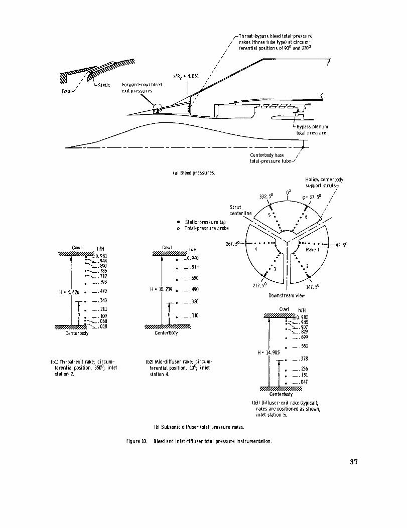
/-Throat-bypass bleed total-pressure/ rakes (three tube type) at circum-
// ferential positions of 90o and 270°/
//
yf /_" _Rc'4O51/"" /'',-staticForwar,cowlb,eedI '_/"Total J exit pressures If
I
L. Bypass plenum
total pressure
(a)Bleedpressures.
Centerbody base /'
total-pressure tube -/
Cowl hlH
_0. Q81
| ,_,_. 785I "_-,._. 712
• _. 593
H-5.626 • _.470
• __ 343
To _. 211
Ih • __.109
I .__ Oh8
Centerbedy
(bl) Throat-exit rake; circum-ferential position, 3900; inlet
station 2.
o _.320
.......J..L...;;."°Centerbody
Hollow centerbodysupport struts7
//
_o= 27.50 /0o
332.5o I
\.,_ / /Strut A ._ ]
centerline / _ • ,'. _ /
• Static-pressuretap _.<".. " °° 3 .0 ..,_/
o Total-pressure probe _ __
cow, 267.5o-I-- -. • ""I, t ..... ".J-92 50_//////////////,,_ hJH \ " '_. .#/ Rake l l '
t • _o.++ \ .: .. /
/ . _.+50 ]-...._H = i0.239 • __. 490 212.50 147.50
Downstream view
Cowl h/H
.__ .945
/ ..,_. 907I __. 8@
. --. 699
| . _. 552H = 14.905
. _ .378
o __. 236
h . __. 151
I [ "--'iiiiiiiiiiiiiii12 7
Centerbedy
(b3) Diffuser-exit rake (typical);
rakes are positioned as shown;inlet station 5.
(b2) Mid-diffuser rake;, circum-
ferential position, 1O°; inlet
station 4.
(b) Subsonic diffuser total-pressure rakes.
Figure 1O. - Bleed and inlet diffuser total-pressure instrumentation.
37

• Static-pressure tap
o Total-pressure probe
x/Rc 3.069 __
.-_ / /Rake A---" JRake B _-RakeC
Reference
station
(dR c = 3.091)
"///////////////////,_ h IH
I -- "
Slot height, H, II1.363 I_l -- .745
_//////_////////////,_,I _ -_:_4
1]363 ,h [_ __ .402
H'i J-H__.I______y _LO0
Upstreamslot surface
"/////////////////////¢(^hlH
1 h_H -u'wo
H= 1.363 I_ __ .605
(a) Rake A; axial distance
ratio, x/R,. = 3.069; cir-cumferen_'ial position, 5°.
(b) Rake B; axial distance
ratio, X/Rc= 3.21_ cir-cumferential position, 20o.
(c) Rake C; axial distance
ratio, )dRc - 3.33.5, cir-cumferential position, 3500.
Slot static-pressure taps,
top centerline
Tube Axial distance from
reference station,
L/Rc
1 0.015
2 .052
3 .088
4 .124
5 .2006 .244
l .204
8 .347
9 .470
10 .613
II .760
Figure ii. - Forward-slanted-slot pressure instrumentation.
38

'6
mm
£a;
8
9-
a:
+
mm
Increasing bleed-exit area
r Inlet minimum_ F _ stable operation
/N bleed-exitarea
•..-.. / \
', \&f_-1
L Supercritical-bleed airflow
Thmat-bypass-bleed mass-flow ratio, mtblm0
(a)Throar-bypass performance.
F- Inlet minimum/" stable operation
H F / D
E C A
,-Lines of
I ,'I constantk'I bleed-exitI I area
Increasing bleed-exit area
Diffuser-exit mass-flow ratio, m5/m0
(b) Inlet performance.
l'ypical constant- rlnlet minimum stableoperation
pressure control / ..--- B
,forS, Icp >] ._ "__ -r" Lines of constant
+,, ...o-.-+/'---_ -- I_ncreas/H E ing
S exit area
bleed-
Airflow index, AI
(c)Airflow index.
Figure ].2. - Inlet stabilitydata.
39

a_° _ _ Lines of constant
__-__d-exit area
-_ H E
J
C
area
Constant-pressure stability index, Slcp
Id) Stability index for constantth roar-bypass bleedrecovery.
r .>.,.-Lines of constantbleed-exit area
I J HDiffuser-exit total-pressure recovery, Ps/Po
(el Variation of constant-pressure stability index with inlet total-pressu re recovery.
I j
Total-cowl-bleed mass-flow ratio, mct/m0
(f_Constant-pressure stability index for an initial inlet total-pressurerecovery of O.89.
Figure 12. - Continued.
4O

8
,=-
0
x
T
...,,__n Iet performance
rom fig. 12(b)
_/ ! /lr _'_"point
_Supercriticalbleed
Rangeofstableinlet operation
(SIcp)
Diffuser-exff mass-flow ratio, ms/m0
(g) Inlet performance for point J as match condition and with constant-pressure control on throat-bypass bleed.
Figure 12. - Concluded.
41

=o
c
o
I!I
I
I
/
/,
It'1
I
o.
0d/_d 'f_a^0_J eJnsseJd-le_0t
r_
._o-
t_
_E
o
o
__°,_
._ _ .
__-£E E -
_'_
c_
42


.5
_.4
eo
,1'
0
•05 .10 .15 .20
Throat-bypass-bleedmass-flow ratio, mtb/m0
la) Throat-bypass performance.
/f
J/
/
5 10 15 20 25 30Airflow index, AT
(cl Airflow index.
.25
L
91 i
ou_
o_
E
o
o
i _1_
.8 " I
.7
i
i
i '!
.9
Mass-flow ratio, mslm 0
(bl Inlet performance.
2
0 5 10 15 20 25
Constant-pressure stability index, SIcp
(dt Stability index for constant throat bypassrecovery,
1.0
Figure 14. - Perlormance of distributed porous configuration NA. Free-stream Mach number, M0 =2.50; angle of attack, a - 0°;overboard-bypassmass-flow ratio, mby/m0 = O.0175.
44

40
30
.80 .84 .88 .92
Total-pressure recovery, Ps/Po
(e) Variation of constant-pressure stability
index with inlet total-pressure recovery..4
,=-to'6 "
o Centerbodyo Forward cowl
O1 .02 .03
Bleed mass-flow ratio, mb/m 0
(g) Forward-cowl and centerbody bleed
performance.
I
I 0 If
1i;
• d5 .10 . ]3 .20
Bleed mass-flow ratio, mtb/m 0
(f) Variation of inlet recovery with throat-bypass bleed.
g-
!51
351
/
.7 .8
Mass-flow ratio, ms/m 0
(hi Distortion.
o
if
I.)
Figure 14. - Concluded.
45

.7
5
4
3
9".2
.,9
!
o__.4
_..2
ao 0 5
"\\ "D-- ......
• .1"
_r_ -,_
0.. O
J
•05 . l_l .15 .20Throat-bypass-bleedmass-flow ratio, mtb/mO
(alThroar-bypassperformance.
1.01-
E
.7.25 .6 .7
Supercrit icalcenterbodybleed,
mb/m0
[]O.023• .031
.9
Mass-flow ratio, ms/m0
(b} Inlet performance.
1.0
l0 15 20Airflow index, AI
(c) Airflow index.
_ .4>......._...__________---o
25 30 0 5 10 15 20 25 30
Constant-pressure stability index, SIcp
(d) Stability index for constant throat bypassrecovery.
35 40
Figure 15. - Performanceof distributedporous configuration NB. Free-streamMach number, M0 • 2.50; angleof attack, n, 0°; overboard-bypassmass-flow ratio, mby/m0 • 0, 0175.
46

8"
x"
•_zo -%
_ lo °,,.
g
o .80 .84 .88 .92 .96 1.00
Total-pressurerecovery, Ps/Po
(e) Variationof constant-pressure stabilityindexwith inlettotal-pressure recovery.
1.0
3O
2O
o---.-__.
"-----.o0.04 .OB .12 .16 .20
Cowl-total-bleed mass-flow ratio, mct/m0
(f) Constant-pressurestability index for an initialinlet total-pressurerecoveryof O.89.
=o
8
o.
.9
.80 •05 .10 .15 .20
Bleedmass-flow ratio,mtb/m0
.3
P
.25 .01
(g) Variationof inlet recoverywith throat-bypassbleed.
.20
_. 15
o
__. 10_.=
.05,.l .8 .9
Mass-flowratio, m5/m0
(i) Distortion.
I/
//
ql
o Centerbody
o Forwardcowl (_I
.02 .03
Bleedmass-flowratio, mb/m0
th) Forward-cowland centerbodybleedperformance.
1.0
Figure15. - Concluded.
47

o__
>o
9-
'6
oa
e:
D(xa
.6
.5
.4I
.]
.2
.i
.6
.5
\% i_\ i
", I
\\\\_i
•0.5 .i0 .15 .20
Throat-bypassbleedmass-flow ratio,mtb/mO
(a)Throat-bypassperformance.
/J \
i\/j2C_,
I
//
/
0
"---o
5 10 15
Airflow index, AI
(c) Airflow index.
o._
8
1.0] T ;
•81.7 .9
Mass-flow ratio, m5/m 0
(b) Inlet performance.
0 5 10 15 20 25
Constant-pressure stability index, SIcp
(d) Stability index for constant throat-bypass recovery.
20 25 50
].r 0
Figure 16. - Performance of distributed porous configuration NC. Free-stream Mach number, M 0 : 2.50; angle
of attack, a = 0°; overboard-bypass mass-flow ratio, mby/m 0 = 0. 0]75.
48

_xI C:r"
o:(._
2O
0.84 .88 .92 .96
Total-pressurerecovery,Ps/P0
(el Variation ofconstant-pressurestability indexwith inlet total-pressure recovery.1.0
20
l C
_'-
1.00 _ 0 .04 .08 .12 .16
Cowl-total-bleedmass-flow ratio, mct/m0
(f) Constant-pressure stability index for an initial inlettotal-pressurerecovery ofO.89.
.20
o.
t_
n=
.9
.80
/ \\
i
•05 .10 .15 .20
Bleedmass-flowratio, mtl_m0
(cj)Variation of inlet recovery with th mat-bypassbleed.
.20
Ia Centetlx)dyo Forwardcowl
J1 .0_ .03 .04
Bleedmass-flow ratio, mb/m0
(h) Forward-cowlandcenterbodybleedperformance.
- . 15
o
o_ . 10¢::
•O.=.7 .8 .9
Mass-flowratio, ms/m0
{i) Distortion.
Ficjure16.- Concluded.
1.0
49

'\%.3
__ .2i
.1
0
,=.
.6
i
.5
.4
.3
.2
.!0
\\\
Y\'I7.. f
• 05 .10 .15 .20
Thmat-bypess-bleed mass-flow ratio, mtb/m 0
(a) Th roat-bypass performance.
\,
D
5 I0 15 20 25
Airflowindex,AI
(c)Airflowindex.
//
/
.25 .6 .7
Figure 17. - Performance for distributed porous configuration ND.
bypass mass-flow ratio, mby/m 0 - O.0175.
a, no. l.6°;
c°Un_ant etb/eO -7
%ns "4"%0; mtbBnO ° 0.0 j
l
Mass-flow ratio, ms/m 0
(b) Inlet performance.
.9 1.0
\ ----...,
5 10 15 20 25 30 35 40
Constant-pressure stability index, SIcp
(d) Stability index for constant throat-bypass recovery.
Free-stream Mach number, M0 - 2.50;, angle of attack, o - 0°; overboard-
50

x"
3
3O
20 i 20
=,-H_w
IC
o 3.80 .84 .88 .' .96 1.00
Total-pressurerecovery,Ps/Po
(elVariation of constant-pressure stability index with in-
let total-pressure recovery.1.0
0 .04 .08 .12 .16 .20
Cowl-total-bleed mass-flow ratio, mcl/m 0
if) Constant-pressure stability index for an initial inlet
total-pressure recovery of O.Bg.
I
=
I
.9
• 05 .10 .15 .20 .25
Bleed mass-flow ratio, mtb/mO
Cente_odyForward cowl
• 01 .02 .03
Bleed mass-flow ratio, mb/m 0
.04
(gl Variation of inlet recovery with throat-bypass bleed.
• 2O
.1.5oI=o
. I0
.05.O
(h) Forward-cowl and centerbody bleed performance.
/
.7 .8
Mass-flow ratio, ms/m 0
(i) Distortion.
.9 1.0
I
II II
Figure 17. - Concluded.
51

.6;
.5
I
.4
I
.3
.2
- .1
,0-
.5
.4
.3
.2
.10
\
\
\
•05 . ]0 . ]5 .20
Throat-bypass-bleedmass-flow ratio, mtb/mO
_a)Throat-bypassperformance.
j/ff
2 ",
---_ --_ _..__
5 i0 15 20
Airflow index, A1
ic)Airflow index.
25 3O
.25
I.C
.9
y_
.8.l
//
/
°uns fi edauns = . , constant Ptb/Po ,7
/I
%ns _ 4. %o mtb/mO = O.0 z
1.9
Mass-flow ratio, ms]m 0
ib) inlet performance.
\%
2 v
]0 5 10 15 20 25 30
Constant-pressure stability index, SIcp
(d) Stability index for constant throat-bypass recovery.
Figure 18. - Performance for distributedporous configuration NE. Free-stream Mach number, M0 =2.50; angleof attack,o =0°; overboard-bypassmass-flow ratio, mby/m0 =0.0175.
1.0
52

-_3o _3o
20 >_ 20
oo .80 .8Zl .B8 .92 .96 1.00 _ 0
Total-pressure recovery, P5/Po
(e) Variation of constant-pressure stability index with inlet
total-pressure recovery.1.0.
_-----------c_.
• 04 .08 .12 .16
Cowl-total-bleed mass-flow ratio, mct/m 0
.2O
(f) Constant-pressure stability index for an initial inlet
total-pressure recovery of O.89.
o
,,?-
[/// \_-\
I-,
.80 • 05 .10 .15 .20
Bleed mass-flow ratio, mtb/m 0
(g) Variation of inlet recovery with th mat-bypass bleed.
• 20
.25
.3
.2
.1.01
Ia Cente rbodyo Forward cowl
• 02 .03
Bleed mass-flow ratio, mb/m 0
. .15
8I=
o
.05.7
(hlForward-cowl and centerbody bleed performance.
e
.9
Mass-flow ratio, ms/m O
(i) Distortion.
.04
Figure 18. - Concluded.
53

.6
.5
.4//
\\
\
/f
•05 .10 .15 .20
Throat-bypass-bleedmass-flow ratio, mtb/m0
(a)Throot-bypassperformance.
.Z5
l o 1 1
9
.7
Ouns - 4.460; fixed exitauns - 4.4@; constant Ptb/Pov
Mass-flowratio, ms/m0
(b)Inletperformance.
//
/
/
1.0
.10
-.\
\
15 20 25Airflow index, AI
(c) Airflow index,
5 I0 30 35 0 5 lO 15 20 25 30 35
Constant-press ure stability index, Slcp
(d) Stability indexforconstantthroat-bypassrecovery.
Figure 19. - Performanceof distributedporous configuration NF. Free-streamMach number, M0 • 2. 50; angleofattack, o - 0°; overboard-
bypassmass-flowratio, mby/m0 - 0.0175.
54

x
,=-C
o_
40
10
0.80 .84 .88 .92 .96 ).00
Total-pressure recovery, Ps/Po
(e) Variation of constant-pressure stability indexwith inlet_ressure recover
1.0
40
3O
0 .O4 .08 .12
Cowl-total-bleedmass-flowratio, mct/m0
(f) Constant-pressurestability indexfor aninitial inlet total-pressure recoveryof O.89.
I:1,.
.80
tII
•05 .10 .15 .20Bleed mass-flowratio, mtb/m0
(g) Variation of inlet recoverywith throat-bypassbleed.
• 25
3
i02 .03 . O4
Bleedmass-flow ratio, mb/m0
(h) Centerbodybleedperformance.
.20.
• 15
o-a .o I
.7 .8 .9 1.0
Mass-flow ratio, ms/m0
(i) Distortion.
Figure 19. - Concluded.
55

•9i
.7 i
.6'
.4 _ o
_ Theoretica \_
/IY !supersonic -_ "- P__ .2 .._. o
_ .1 . _._ -'nc I
,v _ thr°_'_z -Bleed region0 - I I2 ) 4 5
J r_Tot_-pre!su re I Mas!-flowl
/ recovery, rat io,PSi0 m5_o
n 0.94 0.71.94 .72
.94 .72
.95 .81
.94 .91
.93 .92
._ .95
.86 .95 (Super-critical)
.,r
o
m
o
.o
6 ?
(
_.J_--Bleed
regions_ ') amI_['
2 3
i
\
r
,_Geom rlc throat
I 14
Axial distance from cone tip, X/Rc, inlet radii
(a) Internal cowl surface pressure distributions.
I.C
,- LenteL __ r Centerbody _ _L/ _urfa_ _. ' surface0 - _ , _,_-/--_-_,d
.3 .4 .5 .6 .7 .8 .9 l.O .6 .l .8 .9 l.O
Local lotal-pressure recovery, P[/Po
(c) Throat exit, station2. Symbolsat h/H of O (dlMid-diffuser, station4. Symbolsat
and LO represent inlet surface static pressures, h/H of 0 and ]. 0 represent inlet sur-face static pressures.
, , i
n__
/
[heoretical supersonic
6 7 8
(b) Centerbody surface pressure distributions.
,' 1 %_ ._Q."t.._Cowl 0 P
surface _, P
r Centerbody,' surface
.6 .7
I
I
.8 .9 1.0
(e)Diffuser exit rake 6, station 5. Sym-
bolsat h/H of Oand 1.0 represent
inlet surface static pressures.
Figure 20. - Diffuser static- and total-pressure distributions for configuration NF. Distributions are presented for one supercritical condition (throat-
bypassmass-flow ratio, mtb/m 0 - 0) and for all unstart limit data.
56

n
IiE_o"
w
Od/_d '/daAo_aJ aJnssaJd-le_Ol
/k/
I
/I
/
/ //
//
/
//
//
/
N
0d/q_ d '_Ja^o3aJ aJnssaJd-lep_ paal'8
E
o
E
o
0d/ql d '/d_ooaJ aJnssaJd-IE_] Paal8
,/
, / !
\\ /
, !
o_
, _._ _,
o g
z
_ g
o
• ° ,
Od/(P,d '_Ja_o_aJ aJnssaJd-iI_:toiPaall]
_Kr_
_.E
,.-_Eoa
57

40
x"_3o
20
c
80
a_
1.0r_
\ \.84 .88 .92 .96 LO0 L04
Total-pressure recovery, PsIPo
(e) Variationof constant-pressure stabilityindexwith inlet total-ressure recover
30 c_
20 "_-
0 .04 .08 .12 .16 .20 .24
Cowl-total-bleedmass-flow ratio,mct/rn0
(f) Constant-pressurestabilityindexfor an initial inlet total-pressurerecoveryof O.89.
,z
/ t
•05 . ]0 .15 .20 .25
Bleedmass-flowratio,mtb/m0
(g) Variationof inlet recoverywith throat-bypassbleed.
.ZO
1.30 .01
• 15
¢:.o_
.10
c
.05;
0.6
it-- --_
.7
Mass-flowratio, ms/m0
(i) Distortion.
d
1I"
J
.0_ .03
Bleedmass-flowratio, mb/m0
(hi Centerbodybleedperformance.
/I
I/
.9 1.0
.04
Figure 21. - Concluded,
58

.__ 1.6N
E
1.4
o _-
.__d 1.2
I
i
sPbp
Cowl_ Throat bypass
Configuration
o NA
[3 NB
o NC
ND
.4 NE
NF
o NG
o NH
f
A_I-o
1.8---- ] ..... ]---
0 .04 .08 .12 .16 ._0 .2_ _- _Minimum stable throat-bypass-bleed mass-flow ratio, mtb ' m in s/mo
Figure 22. - Distributed-porous-cowl bleed recirculation pressure ratios for minimum stableconditions.
59

,-_ o'_ ////tl ,i i_
I:: I::: I
-_ i=i I
£J]
] = o
I
0d/q] d '_aAo3aJ aJnssaJd-le]olpaal8
Od/qld 'XJaAo3aJ aJnssaJd-iR_o I paal8
"_ _
'S'//
._ 1
o _,
0d/ql d '_a^o_aJ aJnssaJd-l_Ol paa18
E
_, :=z
8.__ o_
_E
6O

x _
o
E
4o
3o
2O
lO
LO
0•80 .84 .88 .92 .96 1.00
Total-pressure recovery, P5/PO
(e_Variation of constant-pressure stability index with inlettotal-pressure recovery.
4O
_" 30
'_ 2c
g 1C
0 •04 .08 .12 .16
Cowl-total-bleed mass-flow ratio, mct/m0
(fl Constant-pressure stability index for an ini-tial inlet total-pressure recoveryof O.89.
.g
.80
.s.....SY J
•05 .10 .15 .20 .25
Bleedmass-flow ratio, mtb/m0
(g) Variation of inlet recovery with th roat-bypassbleed.
.Z5
.20
- .15
1=
o_3"_ . lO
.3O
•o5
0.6 .8
Mass-flow ratio, m.5/m0
(il Distortion.
Figure 23. - Concluded.
.3
.2
.1.0_
.9
Yf
.03 .04
Bleed mass-flow ratio, mb/m0
Ih) Centerbody-bleedperformance.
1.0
61

I.7 _
.6
.5
.4
.3
.2
C, 0
too
E
_a
o
m
o
._o
//
(
_Bt_ _dre_ion:
.8
.7
6 I
Angle Total- Mass- Bleedof pressure flow exit -
attack, recovery, ratio,
a, Ps/Po m 51mo
o 0 0.89 0.94 Closed
a 4.96 .86 .89 Closed
.3 _ 'o
.2/
/.] JjBle j
2
\
\\_ ......Theoretical supersonic
,- Geom ,,tricl
,_= thrr_ :
(al Cowl surface; mtb/m0 =O.O.
J
f
,..o" L j
/
Ancjleof
attack,
deg
o Oo 7.6
Total-
pressurerecovery,
P_Pn
0.89
.83
\
rGeometric
/ throat
4
Theoretical supersonic
5 6
C'
.O" .A3__-- 11 _ ---O
_,, "..S Theoretical supersonic I i
Bie_d _-_ i
i
j ,-Geometric_ ;throat J
(bl Cenlerbody surface; mtb/m 0 = 0. 0.
Mass- Bleed exit -flow
ratio,
ms/m 0
O.g_ ..........................
.85 Varied to maintain constant
bleed recovery
fr
I /'11 r Geometric
., _, !_ro_,47 8 2 3
Axial distance from cone tip, X/Rc, inlet radii
f Theoretical supersonic
-I-- --1----- ,
6 7 8
(c) Cowl surface; mtb/m 0 o 0.026 for _ - 0° condition. (dt Center'body surface, mtb/m 0 =0.026 for a = 0° condition.
Figure 24. - Diffuser static-pressure distributions for configuration ND for an initial operating condition and for the unstart angle-of-attack limit, for
throat-bypass mass-flow ratios mtb/m 0 of 0 and 0._6.
62

.8
.7
.6
.5
.4
E
o .8o
.7
__ .6
.o
g.
I'
ill ___ Angle Total- Mass- Bleed exit -
of pressure flow
attack, recovery, ratio,
-- a, PsIP0 mslm 0deg
. z_ 0 0.89 0.92 Fixed
c J"
-_Blee_ --,- Geometr ic
'regions_. i throa tI n _,_ I I
o 7.38 .84 .86 Sameas a=0 °
_-_ [3 7.60 .83 .84 Varied to main-rain constant
bleed recoveryI. I I I ]
I/, .Theoretical supersonic
(a) Cowl surface.
_o
5
• \\ //--Theoretical supersonic
.2 \,.. -__
ns ........• 1 u / rGeom.et ric
throatI I
2 3 4 5 6 7 8
Axial distance from cone tip, x/Rc, inlet radii
Ib) Centerbody surface.
Figure 25. - Diffuser static-pressure distributions for configuration NEfor an initial operating condition for angle of attack of zero degrees and
for the unstart angle-of-attack limits with fixed bleed exits and variable
bleed exits to maintain a constant bleed recovery.
63

.8
.7
.6
.5
.4
i
--°/
I _ Angle of Total- Mass-
_ _'R-_'-- attack, pressure flow
(_, recovery, ratio,
deg Ps/Po ms/m 0
_ [] 4.6 .87 .90
Geometric
throat-_I , .Bleed
' "" region
-_.3
.2
m
E
0
i
.8L
o
"_ .7
Bleed exit
Fixed exit
Fixed exit and
also for con-
slant bleed
recoveryI l I I
Theoretical supersonic
' -t f I
(alCowl surface.
f.,_ O--f--
__"_ .6 _I1_0
o If,3 %,
f _ _" - Theoretical supersomc.2 '- .
• I Bleedr_ ,-Geometric I
O regions-,_ ,, j, throat[
2 3 4 5 6 7 8
Axial distance from cone tip, X/Rc, inlet radii
(bi Centerbody surface.
Figure 26. - Diffuser static-pressure distributions for configuration NFfor an initial operating condition for angle of attack of zero degrees and
for the unstart angle-of-attack limit with fixed bleed exits and variable
bleed exits to maintain a constant bleed recovery.
64

.95 --
C,,', .go
0._
8
-_ .85
Bleed configuration Stability index,
S1cp
SA 19.6
SB 20
-- --- SC ]g. 2
19. 5_ _'L= _- =._ _..... --- SD
•8a L I , I I I.1 .8 .9 1.0
Mass-flow ratio, ms/m 0
Figure 27. - Comparison of inlet performance for lai'ge-forward-slanted-slot throat-bypass configurations
based on a constant throat-bypass recovery to unstart limit from initial inlet conditions of 89-percent total-
pressure recovery and total-cowl-bleed mass-flow ratio of O.02. Free-stream Mach number, M 0 = 2.50;
angle of attack, o = 0°; overboard-bypass mass-flow ratio, mby/m 0 = O.0175.
65

.6z T
.5
,,?-- 3!
d_
.2I!
d
3
.6
.5
.4
• 05 .10 . ]5 .20
Throat-bypass-bleed mass-flow ratio, mtb/m 0
fa} Throat-bypass performance.
/
.3 t- ....
.20 5 10 15 20 2.5
Airflow index, AI
tO Airflow index.
1.0[
2
, d
o
L
15I---
.9
.8
I
i
Oun s = 4. 770; fixed exit
aun s = 6.60; constant Ptb/Po 7
11
J
2-%
d
L
.7
.4
.8 .9
Mass-flow ratio, ms/m 0
Ib_ Inlet performance•
1.0
.2 ......
0 5 t0 15 20 25 30
Constant-pressure stability index, SIcp
(dl Stability index for constant throat-bypass recovery.
Figure 28. - Performance of forward-slanted-slot configuration SA. Free-stream Mach number, 1'40= 2.50; angle
of attack, u = 0°; overboard-bypass mass-flow ratio, mby/m 0 = 0. 0175.
66

8-3O
-"= 20
10
c
.84 .88 1.00
Total-pressure recovery, Ps/Po
(e_Variation of constant-pressure stability indexwith inlet total-pressure recovery.
1.0
8- 3O
2O
I10
•04 .08 .12 .16
Cowl-total-bleed mass-flow ratio, mct/m0
.20
If) Constant-pressure stability index for an initial inlettotal-pressure recovery of O.89,
6
o
ea
eo
.gl
.80
.....
U
• 05 .10 .15 .20Bleed mass-flow ratio, mtb/m0
(g) Variation of inlet recovery wffh throat-bypassbleed•
•20I
15
_ .lo
.05 ,_
0.1
¢3_
>
_ 2
Centerboctyo Forward cowl
i_dJ
z j
.01 .02 .03Bleed mass-flow ratio, mb/m0
(hi Forward-cowl and centerbody bleedperformance.
1.0
f/
.g
Mass-flow ratio, ms/m0
It) Distortion.
.04
Figure 28. - Concluded•
67

.6
,=-
"._ I I
_ ,
d, . j
"_ i I I J
j I ,
i
I
•05 .lO .15 .20
Throat-bypass-bleedmass-flow ratio,m_Im 0
(at Throat-bypass performance.
.6
10 15 20 25
Airflow index, AI
(c) Airflow index.
IJ
O_
d
o
I.OT
.9_
.8
.I
I
IOun s =4.59o; fixed exit
(]uns = 6"400; constant Ptb/Po-7
i/
• /!
.9
Mass-flow ratio, ms/m 0
(b) Inlet performance.
1.0
.2
.1_ _''° _
0 10 15 20 25
Constant-pressure stability index, Slcp
(d) Stability index for constant th roar-bypass
recovery.
Figure 29. - Performance of forward-slanted-slot configuration SB. Free-stream Math number, M0 = 2.50;
angle of attack, o = 0°; overboard-bypass mass-flow ratio, mby/m 0 = O.017.5.
68
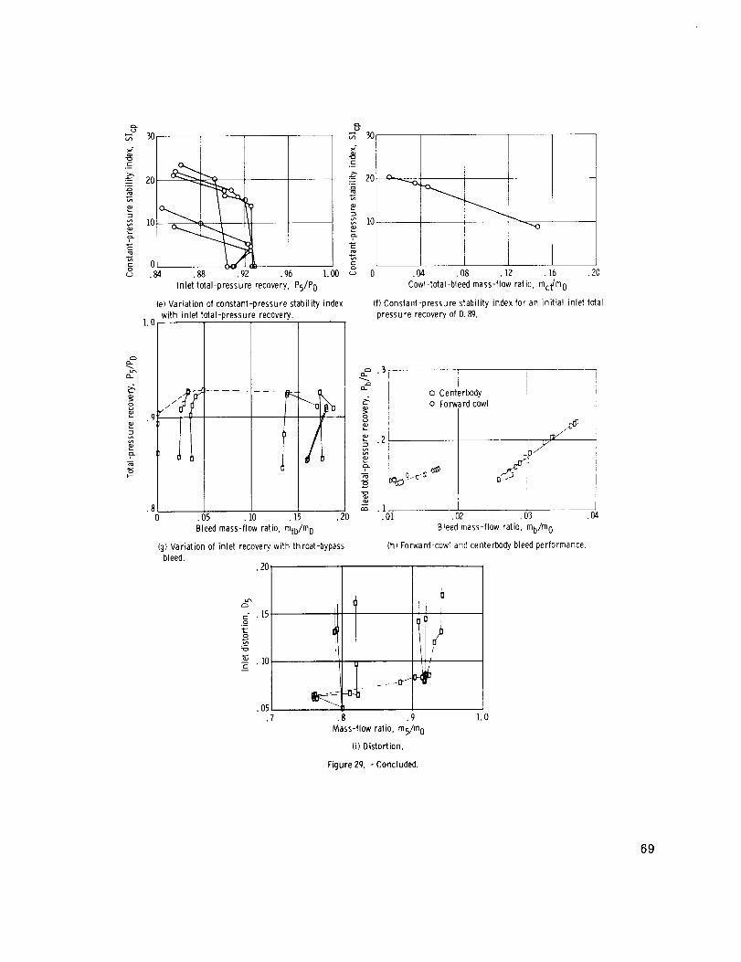
.g
,=-E
o
3O
20 _
0 k•84 .88 .92 .96 I.O0
Inlettotal-pressurerecovery,Ps/Po
(e)Variationofconstant-pressurestabilityindexwithinlettotal-pressurerecovery.
1.0
,%
3O
2O
]0
•04 .08 .12 .16 .20
Cowl-total-bleed mass-flow ratio, met/toO
(f) Constant-pressure stability index for an initial inlet total-pressure recovery of O.89.
,=-
.9
.80
/'/ "0
7.-/ I,
(
• 05 .10 .15
Bleedmass-flow ratio, mtb/m0
(g) Variation of inlet recovery with throat-bypassbleed.
•20
c" • 15
o-N
. ]0c
.05.7
ia Centerbodyo Forward cowl
2[• i
n_
.01 .02 .03 .04
Bleed mass-flow ratio, mb/m0
(ht Forward-cowl and centerbody bleedperformance.
q_i 0"/ >
.8 .9
Mass-flow ratio, ms/m0
(i) Distortion.
!
1.0
Figure 29. - Concluded•
69

1.0
.9
o_
sE
o
"_ .3
8
"_ .2o_
J
"-t Porous-- ...__Geom et ric_Jcowl Pthroal
bleeds.._ _S, IOt
3 4
7
\ ,-, -lheoretical,?upercritical
\r.
Total- Mass-
pressure flow
recovery, ratio,
%/% msmo
0.86 0.79
o .85 .79
_, .85 .79
o .85 .82
c_ .90 .91
v .86 .92
.86 .94
(a) Internal cowl surface pressure distributions.
;U
/
.8 .9 1.0
1.0 !, Cowl I _'v\
sur!face IX
_s--_ I i _r_
o
o ,
E
R .4
8g
g_
.4 .5 .6 .7
Icl Throat-exit local total-pressure recovery,
station 2. Symbolsat h/H of 0andl.0
represent inlet surface static pressures.
6 7 8 2 3 4 5 6 7
Axial distance from cone tip, x/R o inlet radii
{bWCenterbody surface pressure distributions.
cow,surface " "_
\,
_i_ \'1,,/"It _
\i
I[I ,_ iI
,_ Centerbody
surface j
.6 .7 .8 .g 1.0
Local total-pressurerecover3,,P[IPo
(d)Mid-diffuser localtotal-pressurere-
cover,/,station4. Symbols at h/H of
O and 1. 0 represent inlet surface static
pressures.
.6 1.0
"_- Cowl I -'_ -_--._
surface I;1_t_ \_
),/
r Cente rbodysu rface
.7 .8 .9
(el Diffuser-exit rake 6 local total-pressure
recovery, station 5. Symbols at hlH of
0 and I. 0 represent inlet surface static
pressures.
Figure 30. - Inlet diffuser and throat-bypass slot static- and total-pressure distributions for configuration SB. These pressure distributions are for super-
critical conditions that were obtained for several fixed exits.
70

{
.c=
m
Eo
8E
.c:E1=
o
.£
£
oE
E
"6
._o
1.0
.7--
1Total- IVass-
pressure flow
recove ry, rat to,
Ps/P0 ms/m 0
o 0.86 0.79
o .85 .79
z_ .85 .79
o .85 .82
c_ .90 .91
v .86 .92
.86 .94
/}
//
//
.]-Cowl
// surface // I
0 .2 .3 .4 .5 .6 .7 .8 .9
Local total-pressu re recovery, P[/P0
(f) Local total-pressure recovery for slot rake A. Symbols at h/H of 0
)resent inle) _urface static pressures.
1. 0 ,\, _.i_ \ .
Slot
inner _ - -.8 -- surface -- -.__ _
_ "_,\_
.6
1.0
1.C
.4
//3 1 / </z I /fy
r Slot !• ! ,__.upstream,
surface _ _
0 .1 .2 .5 .6 .7 .8 .9 1.0 -.5
Local total-pressure recovery, P/./P0
(h_ Local total-pressure recovery for slot rake C. Symbols at h/H of 0
and 1.0 represent inlet surface static pressures.
.7
.6
.5
.4
o
.l ---- ---2_SIot.
/ upstreamsu rface
/
o
'/ //
.1 .2 .3 .4 .5 .6 .7 .8
Local total-pressure recovery, P_/P0
iIIi
I(g) Local total-pressure recovery for slot rake B. Symbols at h/H of 0
represenl inlet surface static pressures.
Axial distance from slot leading e_e, LIR c, inlet radii
It) Local pressure distributions on upstream surface of bleed slot.
Figure 30. - Concluded.
1.0
1.0
71

1,0
.g
E=. .8
E
._. ,6
o ,4
163
'_ .2._o
.1
1.0
02
. .8
.J:=
.6eu
o
t_3=
E
,4
o
.o_ . 2
#
/!I
!] ".
/ /I r
Porous__ .__r_Oeometric_jcowl , throat
bleed. ' I II -,_Ipsjoti
3 4
:=Cowl
su rface
x _._ ..0...-3f-_ _O-- _ -_
_ ' Total- MaSs- '
pressure flow,//
.u recovery, ratio,x
P5/PO m5/m 0
-- D 0.91 0.76
o I 1& ,
° ir Theoretical
supersomc a .93 .88,' v .93 .90
.90 .93
" o .86 ._ (super-' " critical)"
6 7
Axial distance from cone tip, x/Rc, inlet radii
JBleed -- r IJeomet_'icregions_ r throat
I '_I I I2 3 4
(al Internal cowl surface pressure distributions.
\I_ su rfa
'x
....--It:Jl---_ ==-'__ ==II.'2
\
\
_./r] Theoretical supersonic
5 6 7
(bl Centerbody surface pressure distributions.
0,4
Ir-Centerbody
_ surface.I_ I._;.5
/'J
.6 .7 .8 .9 1.0
(cl Throat-exit local total-pressure recovery,station 2. Symbolsat h/H of Oand 1.0
represent inlet surface static pressures.
lrCente o I surfacei I^J,_
.6 .7 .8 .9 1.0
Localtotal-pressurerecovery,P[/Po
(d)Mid-diffuser local total-pressure re-covery, station 4, Symbols at h/H
of 0 and 1.0 represent inlet surfacestatic pressures.
.6 .7 ,8 .9 1.0
ie} Diffuser-exit rake 6 local total-
pressure recovery, station 5. Sym-bols at h/H of Oand 1.0 representinlet surface static pressures.
Figure 31. - Inlet diffuser andthroat-bypass slot static- and total-pressure distributions for configuration SB. Pressure distributions are for one super-
critical condition (throat-bypass mass-flow ratio, mtblm 0 = O)and all unstarf limit data.
"/2

l.OI
g I I ITotal- Mass-
.8 _- pressure flowrecovery, ratio,
.=_ pS/po m_Im 0'_ .7 --.= a 0.91 0.76
°l ;.6 -- _
o .93 .88.5_
_ .93 .90E 0 .90 .93
>" .4 _ o .86 .941super-critical)
1 J I
.,,-Cowl
, surface _
0 .l .2 .3 .4 .5 .6 .? .8 .g 1.0
1.0
.9--
_- .8
z•$ .7
46
"_ .6.,9
_z .5
" .4
"6.o
.2
Localtotal-pressure recovery, P[/Po
(fl Localtotal-pressure recovery for slot rake A. Symbolsat h/H of 0 rep-resent inlet surface static pressures.
"',s,ot-"1_Z _\
surface
I
\
,f--_Slot _
'-upstream _/ SOrface ,,
.1 .2 .5 .6 .7 .8 .9 1.0
Localtotal-pressurerecovery,P{/Po
(h)Localtotal-pressurerecoveryforslotrakeC. Symbolsat h_ of0
and I.0 representinletsurfacestaticpressures.
-.5
/:f//
__ _Slot
,- upst ream rt_/ surface
/ I
.l .2 .3 .4 .5 .6 .7 .8 .9 1.0
Localtotal-pressurerecovery,P(/Po
(g)Localtotal-pressurerecover3,forslotrakeB. Symbolsat h/H of0 rep-
resentinletsurfacestaticpressures.
/0 .5
A_ial distance from slot leading edge, L/Rc, inlet radii
(i) Local pressure distributions on upstream surface of bleed slot.
1.0
Figure 31. - Concluded.
73

.I
.7
.6
8
.4
,=-
.3
.2
.I
fJl
la
•05 .10 .1.5 .20
Throat-bypass-bleedmass-flow ratio, mtb/m 0
(al Th root-bypass perfo rmance.
I
\
1,0r
(cl Aidl0w index•
"_ .9Q-
>o{3
_a
,=.
Ouns - 5.630; fixed exit
Ouns ° 6.760; constant Ptb/Po 7/
/
/
//
tol
.7
.6
q
_ .5,
_ .4------
L
i I.8 .9
Mass-flow ratio, ms/m 0
(bl Inlet performance.
_.3 0
10 15 20 25 30 35 0 5 10 15 20 25 30 35
Airflow index, AI Constant-pressure stability index, SIcp
(d) Stability index for constant throat-bypass recovery.
Figure 32. - Performance of forward-slanted-slot configuration SC. Free-stream Nlach number, M0 - 2. 50; angle of attack, a • 0°; overboard-
bypass mass-flow ratio, mby/m0 = 0, 0175.
'/4

2O
10
(_ .80 .84 .88 .92 .g6
Inlet total-pressure _cowry, Ps,/Po
(el Variation of constant-pressure stability indexwith inlet total-pressure recovery.
1.0
"_ .$
B-30
_ O
{
.05 .10 .15 .20
Bleed mass-flow ratio, mtb/m0
(g) Variation of inlet recoverywith throat-bypassbleed.
.]0
•04 .08 .12 . [b .20
Cowl-total-bleed mass-flow ratio, mct/m 0
(f) Constant-pressure stability index for an initial inlet total-pressure recovery of O.89.
•41
o Centerbodyo Forward cowl
.01 .02 .03 .04
Bleedmass-flow ratio, mb/m 0
(h) Forward-cowl and centerbody bleed performance.
.25
c" .20
,.9,0
-_ . 15
• ]0
• O5.7
Ita-
.8 .9
Mass-flow ratio, m5/m 0
(i) Distortion.
Figure 32. - Concluded.
1.0
'75

C%
o
o
i
.2
.1
.6
\
• 05 .10 .15 .20
Throat-bypass-bleed mass-flow ratio, mtb/m 0
(a) Throat-bypass performance.
_.5
o> .4 \
.3 - --'_
_.2 . ?-- D 0"
.I
0 5 lO 15 20 25
Airflow index, AI
{cl Airflow index.
1. O
o
e,a
&
I o5.47o;[i I %nsOun s = 1.44°; fixed exit fixed exit [
eun s - 6.76o;Iand constant constant +
1
s%ns = 6. 69o; fixed
Ptb/ PO_
!_ Ptb/PC 7
xff
• 8 %ns = 6.78°; constant Ptb/Po J
.7 .8 .9
Mass-flow ratio, ms./'m0
Ibl Inlet performance.
_!__
0 5 I0 15 20 25
Constant-pressure stability index, SIcp
3O
1.0
<dl Stability index for constant throat-bypass recovery.
Figure 33. - Performance of forward-slanted-slot configuration SD. Free-stream Mach number, M 0 o 2..50; angle
of attack, cz : 0°; overboard-bypass mass-flow ratio, mby/m 0 = O.01.
'76

3Ox"
- o_20
_, 10
g o.84 .88 .92 .96 1.00
Inlet total-pressure recovery, P5/Po
(e} Variation of constant-pressure stability indexwith inlet total-pressure recovery.
1.0 i
8
{
•80 .05 .10 .15 .20
Bleed mass-flow ratio, mtb/mO
qg)Variation of inlet recovery with throat-bypassbleed.
•20_
- 15c '
1=o
c
•05.7
0 .04 .08 .12 .16
Cowl-total-bleed mass-flow ratio, mct/m 0
If) Constant-pressure stability index for an ini-tial inlet total-pressu re recovery of O.89.
8
I
u Centerbodyo Forward cowl
•01 .02 .03Bleed mass-flow ratio, mb/m0
(h) Forward-cowl and centerbody bleedperformance.
.8 .9
Mass-flow ratio, m5/m0
(i) Distortion.
1.0
• /
j/I
Figure 33. - Concluded.
"/7

I.U
.9
_" .8
7
t.o
6E
=
L-
o 4
-_ .3
o .2 /o
• 1-TP0r us-_cow
blee _...02
1.0
fII
\
\ ._-Theoretical supersonic
._c:G ,,omet ic
_ throat
-I F-slot4 5 6 7 8
Axialdistancefrom cone tip,x/Rc, inletradii
(a)(_owlsu dace.
.9
E .8 f _--
_, .o___-I_" .7
E .6
Jfo
.. r,w
"_ \ /--Theoretical supersonic.o_ .<_
Bleed rGeemetric
regions-_-.l _ i t_ roar I
2 3 4 5 6 7
Axialdistancefrom cone tip,x/Rc, inletradii
(b)Centerbodysurface.
Angle of Total- Mass-
attack, pressure flow
a, recovery, ratio,
deg Ps/Po ms/m O
A O 0.91 0.92
o 4.59 .87 .88
o 6.46 .85 .85
Bleed exit -
Fixed exitSame as o =0 °
Constant bleed
recovery
A
o
!- I
r Cowl _
.3 .6 .7 .8 .9 1.0
Local total-pressure recovery, P[/Po
(c) Slot rake A. Symbols at a h/H of 0 represent
inlet surface static pressures.
Figure 34. - Diffuser static-pressure distributions for configuration SB for an initial operating condition and for unstart angles of attack.
Slot rake A data are also presented.
78

.I0 .05 .1o
Throar-bypass-bleedmass-
flowratio,mlb/mo
1.o auns
'auns "6'460; constant Ptb/Po 7
[
• 5. 370; fixed exit
E8
.
t
• l!.8 .9
Mass-flow ratio, mslm0
5 10 ]5 2O
Constant-pressure stability index, Slcp
(d) Stability index for constant throat-bypass recov_
.4
Ib) Inlet performance.
1.0
20
_, 16 --
_, 12
'i
.7
• 84 .88 .92 . go
Total-pressure recovery, P5/Po
(e} Variation of constant • ressure stabilityindex with inlet total- .ressure recovery.
/
_.3>o8
_p
,_".2
o Centerbodyo Forward cowl
.ll.01 .02 .03 .04
Bleedmass-flow ratio, mb/m0
Ig) Forward-cowl andcenterbodybleed performance•
< 5,J
o \
.25¸
q
.] I0 5 10 15
Airflow index, AI
• 2O
g
._5
I
• I°I.05
.8
\
(el Airflow index•
].0
°> .9
.8• 05 . I0
Bleedmass-flow ratio, mtb_'n0
(f) Variation of inlet recoverywith throat-bypass bleed.
.9 1.0
Mass-flow ratio, mslm0
(hi Distorfion.
Figure 35. - Performance of forward-slanted slotconfiguration SS. Free-stream Mach number, M0 - 2. 50; angle of attack,
u - 0°; overboard-bypassmass-flow ratio, mby/m 0 =O.01.
'/9

.9.5--
.90
E
8-
-_. 85--
• 80
Bleed Stabilityconfiguration index,
SIcp
EA 20EB 17.7
I , I J I.8 .9 1.0
Mass-flow ratio, ms/m0
Figure 36. - Comparison of inlet performance for distributed educated-th roat-bypassconfigurations basedonconstant throat-bypass recovery to unstart limit from initial inlet conditions of 8g-percent total-pressurerecovery and total-cowl-bleed mass-flow ratio of O.02to O.03. Free-stream Math number, M0 =2.50; angleof attack, a =0°; overboard-bypassmass-flow ratio, mby/m0 =O.01.
80

.5
_.4
o.2
.1
.5
_.4
iB
_ .Z
m
t I A
•05 .10 .15 .20Throat-bypass-bleed mass-flow ratio, m_/m 0
(a) Throat-bypass performance.
o
CL_
1.0
8.7
1 I
aun s =4.91°; fixed exit%ns = 5. 53o; constant Ptb/Po
! fI
t I
.5
.9
Mass-flow ratio, ms./m0
(b} Inlet performance.
1.0
- IJJ
J/
rl/. j
... --....\
5 lO 15 20 25Airflow index, A!
0
(c) Airflow index.
l]_---o
.--0
3O 0 5 10 15 20 25 30
Constant-pressure stability index, Slop
(d) Stability index for constant throat-bypass recovery.
Figure 37. - Performance of distributed educatedconfiguration EA. Free-stream Mach number, M0 =2.50; angleof
attack, o o 0°; overboard-bypassmass-flow ratio, mby/m0 =O.0I.
81

_aa
Ceo
0
,,?-
3O
2O
I0
0.80
1.0
.g
.80
.84 • 88 .92 .96
Total-pressurerecovery, Ps/Po
(el Variation of constant-pressurestability indexwith inlet total- pressurerecovery.
- j -_o-j_o
•05 .10 .15 .20
Bleed mass-flow ratio, mtb/m0
(gl Variation of inlet recovery with throat-bypassbleed.
.25
3O
l20 j
lO_
0 ._ .08 .12
Cowl-total-bleed mass-flow ratio, mct/m0
Ifl Constant-pressure stability index for aninitial inlet total-pressure recovery of O.89.
L
o,a
.3
.02 .03 .04
Bleed mass-flow ratio, mb/m0
lh) Centerbodybleedperformance.
c
m
•2O
.15
• I0
.o5.8
Mass-flow ratio, m_m 0
li! Distortion.
Figure 37. - Concluded.
II
1.0
82

1.0
.9
cx +8
.7
.6
+i
.4
-- .3 --
,3o
"_ .2.9
1.0
//
¢
Jc.8
..E
== .6
o
to
.o_
\
v _1- I IMass-
pressure flowV" recovery, rat to,
Ps/P0 m5/tn 0
o 0.940 0.773o .940 .789
.944 .807
o .951 .830
c_ .936 .918
v ,925 .927
[; .895 .°A7
I++__ f
+.,p'
/
U)+I
r Geometricthroat
z I
.Bleedregion3 4
"... o .831 .956 (super-" _ critical)
T
5 6 7 B
r r
/ \. _-Theoretical supersonicI%
- Jl= ,-.Geometric _ _ -- _- -- _- -- _ --
Bleed _. I, throatI 1
2 3 4 5 6 7 8
Axial distance from conetip, X/Rc, inlet radii
(a) Internal cowl surface pressure distributions.
su Hate
/
-Centerbo+ J/_.J.i rCenie,o, _." surface / surface
.3 .4 .5 .6 .7 .8 .9 1.0 .6 .7 .8 .9 1.0
Local total-pressure recovery, P[/P0 Localtotal-pressure recovery, P[/P0
(o_Throat exit, station 2. Symbols at h/H of Idl Mid-diffuser, station 4. Symbols at0 and 1.0 represent inlet surface static pres- h/H of 0 and 1.0 represent inlet sur-
su res. face static pressures.
(b) Centerbody surface pressure distributions.
!LCowi i-_
surface _,k "1__ t
r Centerbody _i I surface, L_
.6 .7 .B .9 1.0
Local total-pressure recovery, PS,_/Po
(el Diffuser rake 6, station 5. Symbolsat h/H of 0 and 1.0 represent inlet
surface static pressures.
Figure 38. - Inlet diffuser static- and total-pressure distributions for configuration EA. Distributions are presented for one supercritical condition andall unstart limit data.
83

.4
.2
m
o .'3
.2
Dm
0
t.0
•05 .10 .15 .20Throat-bypass-bleed mass-flow ratio, mtb/m0
(a)Throar-bypassperformance,
5 lO 15 2o 25Airflow index, AI
(c) Airflow index•
(3_
L
c>
.9'
.8.7 .8 .9
Mass-flow ratio, m5/m0
Ib) Inlet performance•
41_'_ _--____________ .°
3\ "'-o
10 5 10 15 20 25
Constant-pressure stability index, SIcp
(d) Stability index for constant t h roar-bypass recovery.
1.0
3O
Figure 39. - Performance of distributed educated bleedconfigurationEB. Free-streamMach number, M0 =2.50;angle of attack, o - 0°; overboard-bypass mass-flow ratio, mby/m0 o 0.01.
84

c
mqo
q
c
gC_3
3O
• 84 .88 .92 .96 1.O0Total-pressure recovery, Ps/Po
(e) Variation of constant-pressure stability indexwith inlet total-pressure recovery.
].0
>_ 20
3 o • _ .08 .12 .16Cowl-total-bleed mass-flow ratio, mct/m 0
(f) Constant-pressure stability index for an ini-tial inlet total-pressure recovery of O.89.
c_
o_
mto
.9
.80
;//z I
i
Eo Centerbody
•05 . ]0 .15 .20
Bleed mass-flow ratio, mtb/m0
(g) Variation of inlet recovery with throat-bypassbleed.
.25
•2O
.15
• I0
•O5
co
c
• 01
I
J
_f_-a
•02 .03
Bleed mass-flow ratio, mb/m0
(hi Centerbodybleedperformance•
.8 .9Mass-flow ratio, ms/m0
(i) Distortion.
1.0
Figure 39. - Concluded.
.O4
85

o
E
o
o
.8
.7
6
5
4
3
2
I
0
.8
.7
.6
.5
.4
.3
.2
.1
0
/
IT
_L-_A_ngl_oof Total- Mass- Bleed ext-
attack, pressure flow__ Q, recovery, ratio, I
deg %/Po mg/mo il_. __ /, 0 0.89 0.94 Fixedexit
I .__ o 4.91 .86 .go Sameas a:O °--_ [3 5.53 .85 .89 Constant bleed
]_i._ - - _] recovery\\ I I ] 1
- Theoretical supersonic
r geometric " -I throat ......j Ij |..-Bleedi/]" region
_'_'_ 1
(at Cowlsurface.
2 3 4 5 6 7 8
Axial distance from conetip, X/Rc, inlet radii
qb)Centerbodysurface.
Figure 40. - Diffuser static-pressure distribution for configuration EAfor an initial operating condition and for unstarl angles of attack.
E Bleed plenum"_ '_ volume,
o: cum_ o 0.01_ (small)
Time o .402 (largel60
5O
x"
.E 30
"E 29
I----
10
I I I I0 10 20 30 40
Transient pulse frequency, ft, Hz
Figure 41. - Unstart limits of inlet system util-izing throat-bypass configuration NFwhensubjected to transient internal disturbances.Free-stream Mach number, M0 =2. 50; angleof attack, a =0°.
86 NASA-La._I_y,1973-- i E-7240


