
Cartridge Valves Technical Information Proportional Valves ... · Proportional valves Cartridge...
52
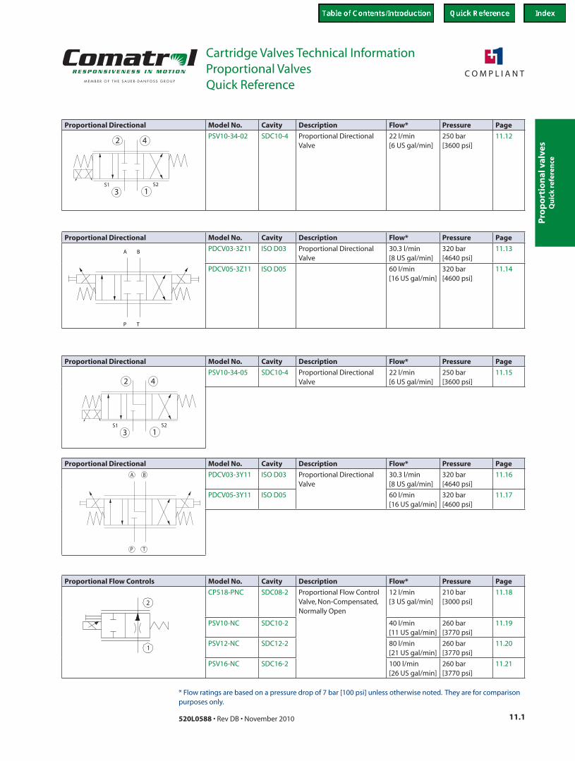
Proportional valves Cartridge Valves Technical Information Proportional Valves 11.1 520L0588 • Rev DB • November 2010 * Flow ratings are based on a pressure drop of 7 bar [100 psi] unless otherwise noted. They are for comparison purposes only. Quick Reference Quick reference Proportional Flow Controls Model No. Cavity Description Flow* Pressure Page 2 1 CP518-PNC SDC08-2 Proportional Flow Control Valve, Non-Compensated, Normally Open 12 l/min [3 US gal/min] 210 bar [3000 psi] 11.18 PSV10-NC SDC10-2 40 l/min [11 US gal/min] 260 bar [3770 psi] 11.19 PSV12-NC SDC12-2 80 l/min [21 US gal/min] 260 bar [3770 psi] 11.20 PSV16-NC SDC16-2 100 l/min [26 US gal/min] 260 bar [3770 psi] 11.21 Proportional Directional Model No. Cavity Description Flow* Pressure Page 3 1 4 2 S2 S1 PSV10-34-02 SDC10-4 Proportional Directional Valve 22 l/min [6 US gal/min] 250 bar [3600 psi] 11.12 Proportional Directional Model No. Cavity Description Flow* Pressure Page 3 1 4 2 S2 S1 PSV10-34-05 SDC10-4 Proportional Directional Valve 22 l/min [6 US gal/min] 250 bar [3600 psi] 11.15 Proportional Directional Model No. Cavity Description Flow* Pressure Page T P A B PDCV03-3Y11 ISO D03 Proportional Directional Valve 30.3 l/min [8 US gal/min] 320 bar [4640 psi] 11.16 PDCV05-3Y11 ISO D05 60 l/min [16 US gal/min] 320 bar [4600 psi] 11.17 Proportional Directional Model No. Cavity Description Flow* Pressure Page P T A B PDCV03-3Z11 ISO D03 Proportional Directional Valve 30.3 l/min [8 US gal/min] 320 bar [4640 psi] 11.13 PDCV05-3Z11 ISO D05 60 l/min [16 US gal/min] 320 bar [4600 psi] 11.14
Transcript of Cartridge Valves Technical Information Proportional Valves ... · Proportional valves Cartridge...
Pro
po
rtio
nal
val
ves
Cartridge Valves Technical InformationProportional Valves
11.1520L0588 • Rev DB • November 2010
* Flow ratings are based on a pressure drop of 7 bar [100 psi] unless otherwise noted. They are for comparison purposes only.
Quick Reference
Qu
ick
refe
ren
ce
Proportional Flow Controls Model No. Cavity Description Flow* Pressure Page
2
1P104 836
CP518-PNC SDC08-2 Proportional Flow Control Valve, Non-Compensated, Normally Open
12 l/min[3 US gal/min]
210 bar[3000 psi]
11.18
PSV10-NC SDC10-2 40 l/min[11 US gal/min]
260 bar[3770 psi]
11.19
PSV12-NC SDC12-2 80 l/min[21 US gal/min]
260 bar[3770 psi]
11.20
PSV16-NC SDC16-2 100 l/min[26 US gal/min]
260 bar[3770 psi]
11.21
Proportional Directional Model No. Cavity Description Flow* Pressure Page
P102 711
3 1
42
S2S1
PSV10-34-02 SDC10-4 Proportional Directional Valve
22 l/min[6 US gal/min]
250 bar[3600 psi]
11.12
Proportional Directional Model No. Cavity Description Flow* Pressure Page
P108 2873 1
42
S2S1
PSV10-34-05 SDC10-4 Proportional Directional Valve
22 l/min[6 US gal/min]
250 bar[3600 psi]
11.15
Proportional Directional Model No. Cavity Description Flow* Pressure Page
TP
A B PDCV03-3Y11 ISO D03 Proportional Directional Valve
30.3 l/min[8 US gal/min]
320 bar[4640 psi]
11.16
PDCV05-3Y11 ISO D05 60 l/min[16 US gal/min]
320 bar[4600 psi]
11.17
Proportional Directional Model No. Cavity Description Flow* Pressure Page
P T
A B
P102 711E
PDCV03-3Z11 ISO D03 Proportional Directional Valve
30.3 l/min[8 US gal/min]
320 bar[4640 psi]
11.13
PDCV05-3Z11 ISO D05 60 l/min[16 US gal/min]
320 bar[4600 psi]
11.14
Pro
po
rtion
al valves
Cartridge Valves Technical InformationProportional Valves
11.2 520L0588 • Rev DB • November 2010
* Flow ratings are based on a pressure drop of 7 bar [100 psi] unless otherwise noted. They are for comparison purposes only.
Quick Reference
Qu
ick reference
Proportional Flow Controls Model No. Cavity Description Flow* Pressure Page
1
2
P104 858
PSVP10-NOR SDC10-2 Proportional Flow Control Valve, Non-Compensated, Normally Open, Poppet Type
45 l/min[12 US gal/min]
260 bar[3770 psi]
11.28
PSVP12-NOR SDC12-2 70 l/min[18 US gal/min]
260 bar[3770 psi]
11.29
PSVP16-NOR SDC16-2 80 l/min[21 US gal/min]
260 bar[3770 psi]
11.30
Proportional Flow Controls Model No. Cavity Description Flow* Pressure Page
CP518-PNO SDC08-2 Proportional Flow Control Valve, Non-Compensated, Normally Open
12 l/min[3 US gal/min]
210 bar[3000 psi]
11.25
PSV10-NO SDC10-2 45 l/min[12 US gal/min]
260 bar[3770 psi]
11.26
PSV12-NO SDC12-2 100 l/min[26 US gal/min]
260 bar[3770 psi]
11.27
Proportional Flow Controls Model No. Cavity Description Flow* Pressure Page
P104 797
PFC10-RC SDC10-2 Proportional Flow Control Valve, Pressure Compensated, Restrictive Type, Normally Closed
30 l/min[8 US gal/min]
260 bar[3770 psi]
11.31
PFC12-RC SDC12-2 65 l/min[17 US gal/min]
260 bar[3770 psi]
11.32
PFC16-RC SDC16-2 90 l/min[24 US gal/min]
260 bar[3770 psi]
11.33
Proportional Flow Controls Model No. Cavity Description Flow* Pressure Page
P104 802
PFC10-RO SDC10-2 Proportional Flow Control Valve, Pressure Compensated, Restrictive Type, Normally Open
30 l/min[8 US gal/min]
260 bar[3770 psi]
11.34
PFC12-RO SDC12-2 60 l/min[16 US gal/min]
260 bar[3770 psi]
11.35
PFC16-RO SDC16-2 85 l/min[22 US gal/min]
260 bar[3770 psi]
11.36
Proportional Flow Controls Model No. Cavity Description Flow* Pressure Page
1
2
P104 854
PSVP10-NCR SDC10-2 Proportional Flow Control Valve, Non-Compensated, Normally Closed, Poppet Type
55 l/min[14 US gal/min]
260 bar[3770 psi]
11.22
PSVP12-NCR SDC12-2 70 l/min[18 US gal/min]
260 bar[3770 psi]
11.23
PSVP16-NCR SDC16-2 90 l/min[24 US gal/min]
260 bar[3770 psi]
11.24
2
1
P104 832
Pro
po
rtio
nal
val
ves
Cartridge Valves Technical InformationProportional Valves
11.3520L0588 • Rev DB • November 2010
* Flow ratings are based on a pressure drop of 7 bar [100 psi] unless otherwise noted. They are for comparison purposes only.
Quick Reference
Qu
ick
refe
ren
ce
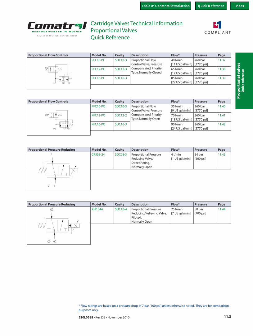
Proportional Pressure Reducing Model No. Cavity Description Flow* Pressure Page
P102 433E
2
1
3
CP558-24 SDC08-3 Proportional Pressure Reducing Valve, Direct Acting, Normally Open
4 l/min[1 US gal/min]
34 bar[500 psi]
11.43
Proportional Pressure Reducing Model No. Cavity Description Flow* Pressure Page
42
3
P102 943
XRP 044 SDC10-4 Proportional Pressure Reducing/Relieving Valve, Piloted, Normally Open
25 l/min[7 US gal/min]
50 bar[700 psi]
11.44
Proportional Flow Controls Model No. Cavity Description Flow* Pressure Page
P104 789
PFC10-PC SDC10-3 Proportional Flow Control Valve, Pressure Compensated, Priority Type, Normally Closed
40 l/min[11 US gal/min]
260 bar[3770 psi]
11.37
PFC12-PC SDC12-3 65 l/min[17 US gal/min]
260 bar[3770 psi]
11.38
PFC16-PC SDC16-3 85 l/min[22 US gal/min]
260 bar[3770 psi]
11.39
Proportional Flow Controls Model No. Cavity Description Flow* Pressure Page
P104 793
PFC10-PO SDC10-3 Proportional Flow Control Valve, Pressure Compensated, Priority Type, Normally Open
35 l/min[9 US gal/min]
260 bar[3770 psi]
11.40
PFC12-PO SDC12-2 70 l/min[18 US gal/min]
260 bar[3770 psi]
11.41
PFC16-PO SDC16-3 90 l/min[24 US gal/min]
260 bar[3770 psi]
11.42

Pro
po
rtion
al valves
Cartridge Valves Technical InformationProportional Valves
11.4 520L0588 • Rev DB • November 2010
* Flow ratings are based on a pressure drop of 7 bar [100 psi] unless otherwise noted. They are for comparison purposes only.
Quick Reference
Qu
ick reference
Proportional Pressure Relieving Model No. Cavity Description Flow* Pressure Page
P103 512
XMP 06 NCS06/2 Proportional Relief Valve, Pilot Operated, Normally Open
50 l/min[13 US gal/min]
315 bar[4500 psi]
11.51
Proportional Pressure Relieving Model No. Cavity Description Flow* Pressure Page
P103 512
XMD 04 NCS04/2 Proportional Pressure Reducing Valve, Direct Acting, Normally Open
5 l/min[1 US gal/min]
250 bar[3600 psi]
11.47
CP558-20 SDC08-2 8 l/min[2 US gal/min]
210 bar[3000 psi]
11.48
Proportional Pressure Relieving Model No. Cavity Description Flow* Pressure Page
1
2
P102 942E
PRV10-POC SDC10-2 Proportional Relief Valve, Pilot Operated, Normally Closed
76 l/min[20 US gal/min]
250 bar[3600 psi]
11.49
PRV12-POC SDC12-2 180 l/min[48 US gal/min]
250 bar[3600 psi]
11.50
Proportional Pressure Reducing Model No. Cavity Description Flow* Pressure Page
P102 433E
2
1
3
PPR10-PAC SDC10-3 Proportional Pressure Reducing/Relieving Valve, Piloted, Normally Closed
18 l/min[5 US gal/min]
250 bar[3625 psi]
11.45
Proportional Pressure Reducing Model No. Cavity Description Flow* Pressure Page
P108 348E
XRP 06 NCS06/3 Proportional Pressure Reducing/Relieving Valve, Piloted, Normally Open
25 l/min[7 US gal/min]
315 bar[4500 psi]
11.46
Pro
po
rtio
nal
val
ves
Cartridge Valves Technical InformationProportional Valves
11.5520L0588 • Rev DB • November 2010
Application Notes
Ap
plic
atio
n n
ote
s
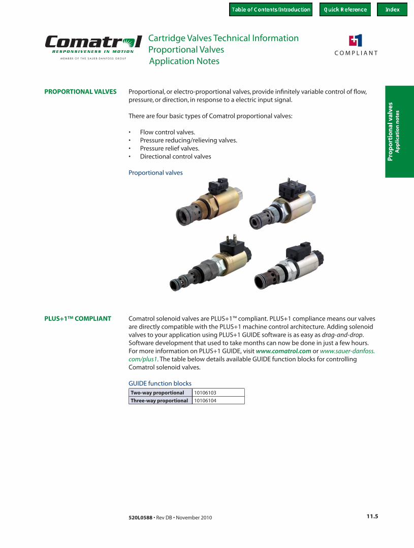
Proportional, or electro-proportional valves, provide infinitely variable control of flow, pressure, or direction, in response to a electric input signal.
There are four basic types of Comatrol proportional valves:
• Flow control valves.• Pressure reducing/relieving valves.• Pressure relief valves.• Directional control valves
PROPORTIONAL VALVES
Proportional valves
PLUS+1™ COMPLIANT Comatrol solenoid valves are PLUS+1™ compliant. PLUS+1 compliance means our valves are directly compatible with the PLUS+1 machine control architecture. Adding solenoid valves to your application using PLUS+1 GUIDE software is as easy as drag-and-drop. Software development that used to take months can now be done in just a few hours. For more information on PLUS+1 GUIDE, visit www.comatrol.com or www.sauer-danfoss.com/plus1. The table below details available GUIDE function blocks for controlling Comatrol solenoid valves.
GUIDE function blocksTwo-way proportional 10106103
Three-way proportional 10106104
Pro
po
rtion
al valves
Cartridge Valves Technical InformationProportional Valves
11.6 520L0588 • Rev DB • November 2010
Application Notes
Ap
plicatio
n n
otes
PROPORTIONAL FLOW CONTROL VALVES
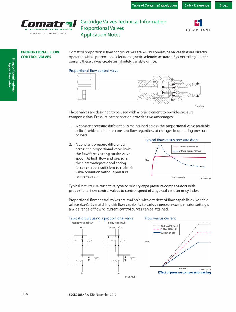
Comatrol proportional flow control valves are 2-way, spool-type valves that are directly operated with a proportional electromagnetic solenoid actuator. By controlling electric current, these valves create an infinitely variable orifice.
P108 349
Proportional flow control valve
These valves are designed to be used with a logic element to provide pressure compensation. Pressure compensation provides two advantages:
1. A constant pressure differential is maintained across the proportional valve (variable orifice), which maintains constant flow regardless of changes in operating pressure or load.
2. A constant pressure differential across the proportional valve limits the flow forces acting on the valve spool. At high flow and pressure, the electromagnetic and spring forces can be insufficient to maintain valve operation without pressure compensation.
Typical circuits use restrictive-type or priority-type pressure compensators with proportional flow control valves to control speed of a hydraulic motor or cylinder.
Proportional flow control valves are available with a variety of flow capabilities (variable orifice sizes). By matching this flow capability to various pressure compensator settings, a wide range of flow vs. current control curves can be attained.
Pressure drop
with compensation
without compensation
Flow
P103 029E
Typical flow versus pressure drop
Restrictive-type circuit Priority-type circuit
In In
OutBypassOut
P103 030E
Typical circuit using a proportional valve
Current
10.3 bar [150 psi]
6.9 bar [100 psi]
3.4 bar [50 psi]
P103 031E
Flow
Flow versus current
Effect of pressure compensator setting
Pro
po
rtio
nal
val
ves
Cartridge Valves Technical InformationProportional Valves
11.7520L0588 • Rev DB • November 2010
Application Notes
Ap
plic
atio
n n
ote
s
PROPORTIONAL PRESSURE REDUCING/RELIEVING VALVES
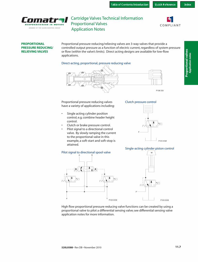
Proportional pressure reducing/relieving valves are 3-way valves that provide a controlled output pressure as a function of electric current, regardless of system pressure or flow (within the valve’s limits). Direct acting designs are available for low-flow applications.
Proportional pressure reducing valves have a variety of applications including:
• Single acting cylinder position control, e.g. combine header height control.
• Clutch or brake pressure control.• Pilot signal to a directional control
valve. By slowly ramping the current to the proportional valve in this example, a soft-start and soft-stop is attained.
P108 350
Direct-acting, proportional, pressure reducing valve
High flow proportional pressure reducing valve functions can be created by using a proportional valve to pilot a differential sensing valve; see differential sensing valve application notes for more information.
W
P
P103 033E
Single-acting cylinder piston control
P
P103 034E
Clutch pressure control
Pilot signal to directional spool valveA B
TPP103 035E
Pro
po
rtion
al valves
Cartridge Valves Technical InformationProportional Valves
11.8 520L0588 • Rev DB • November 2010
Application Notes
Ap
plicatio
n n
otes
PROPORTIONAL PRESSURE RELIEF VALVES
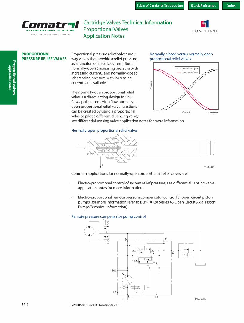
Proportional pressure relief valves are 2-way valves that provide a relief pressure as a function of electric current. Both normally-open (increasing pressure with increasing current), and normally-closed (decreasing pressure with increasing current) are available.
The normally-open proportional relief valve is a direct-acting design for low flow applications. High flow normally-open proportional relief valve functions can be created by using a proportional valve to pilot a differential sensing valve;
Current
Normally-Open
Normally-Closed
Pres
sure
P103 036E
Normally closed versus normally open proportional relief valves
see differential sensing valve application notes for more information.
P
TP103 037E
Normally-open proportional relief valve
Common applications for normally-open proportional relief valves are:
• Electro-proportional control of system relief pressure; see differential sensing valve application notes for more information.
• Electro-proportional remote pressure compensator control for open circuit piston pumps (for more information refer to BLN-10128 Series 45 Open Circuit Axial Piston Pumps Technical Information).
B
P103 038E
X
X
L1S
L2
M2
Remote pressure compensator pump control
Pro
po
rtio
nal
val
ves
Cartridge Valves Technical InformationProportional Valves
11.9520L0588 • Rev DB • November 2010
Application Notes
Ap
plic
atio
n n
ote
s
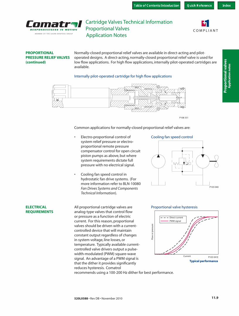
Normally-closed proportional relief valves are available in direct-acting and pilot-operated designs. A direct-acting, normally-closed proportional relief valve is used for low flow applications. For high flow applications, internally pilot-operated cartridges are available.
PROPORTIONAL PRESSURE RELIEF VALVES(continued)
P108 351
Internally pilot-operated cartridge for high flow applications
Common applications for normally-closed proportional relief valves are:
• Electro-proportional control of system relief pressure or electro-proportional remote pressure compensator control for open circuit piston pumps as above, but where system requirements dictate full pressure with no electrical signal.
• Cooling fan speed control in hydrostatic fan drive systems. (For more information refer to BLN-10080 Fan Drives Systems and Components Technical Information).
ELECTRICAL REQUIREMENTS
All proportional cartridge valves are analog-type valves that control flow or pressure as a function of electric current. For this reason, proportional valves should be driven with a current-controlled device that will maintain constant output regardless of changes in system voltage, line losses, or temperature. Typically available current-controlled valve drivers output a pulse-width-modulated (PWM) square-wave signal. An advantage of a PWM signal is that the dither it provides significantly reduces hysteresis. Comatrol
P103 040
Cooling fan speed control
recommends using a 100-200 Hz dither for best performance.
Proportional valve hysteresis
Flo
w o
r pre
ssu
re
Current
Direct current
PWM signal
P103 041E
Typical performance
Pro
po
rtion
al valves
Cartridge Valves Technical InformationProportional Valves
11.10 520L0588 • Rev DB • November 2010
Application Notes
Ap
plicatio
n n
otes
TERMS AND DEFINITIONS Analog Proportional Valves are controlled by electric current, which may be direct current (DC) or a PWM signal.
Compensator is a hydraulic component that maintains a constant pressure drop across a fixed or variable orifice.
Current is the flow of electricity through a conductor or coil, normally measured in amps (A). Steady-state current flow in an electrical circuit can be calculated by Ohm’s Law, as well as voltage and resistance.
Ohm’s Law I = V R
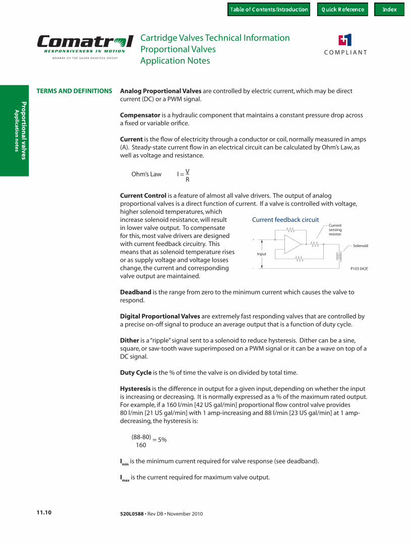
Current Control is a feature of almost all valve drivers. The output of analog proportional valves is a direct function of current. If a valve is controlled with voltage,
Input
Currentsensingresistor
Solenoid
P103 042E
higher solenoid temperatures, which increase solenoid resistance, will result in lower valve output. To compensate for this, most valve drivers are designed with current feedback circuitry. This means that as solenoid temperature rises or as supply voltage and voltage losses change, the current and corresponding valve output are maintained.
Current feedback circuit
Deadband is the range from zero to the minimum current which causes the valve to respond.
Digital Proportional Valves are extremely fast responding valves that are controlled by a precise on-off signal to produce an average output that is a function of duty cycle.
Dither is a “ripple” signal sent to a solenoid to reduce hysteresis. Dither can be a sine, square, or saw-tooth wave superimposed on a PWM signal or it can be a wave on top of a DC signal.
Duty Cycle is the % of time the valve is on divided by total time.
Hysteresis is the difference in output for a given input, depending on whether the input is increasing or decreasing. It is normally expressed as a % of the maximum rated output. For example, if a 160 l/min [42 US gal/min] proportional flow control valve provides 80 l/min [21 US gal/min] with 1 amp-increasing and 88 l/min [23 US gal/min] at 1 amp-decreasing, the hysteresis is:
(88-80) = 5% 160
Imin
is the minimum current required for valve response (see deadband).
Imax
is the current required for maximum valve output.
Pro
po
rtio
nal
val
ves
Cartridge Valves Technical InformationProportional Valves
11.11520L0588 • Rev DB • November 2010
Application Notes
Ap
plic
atio
n n
ote
s
PWM is an acronym for Pulse-Width-Modulation. Most valve drivers use a current-controlled PWM output to reduce valve hysteresis and to allow current control without excessive heat generation. A typical PWM output is a square wave from 80-500 Hz.
Ramping is the application of current to a solenoid with a linear or non-linear ramp, rather than an instantaneous step. Ramping current on and off to a proportional valve provides actuators with soft-starts and soft-stops. Ramps can generally be set or pre-programmed into valve drivers.
Resistance is a component’s opposition to the flow of electrical current, usually measured in ohms (Ω). Resistance depends on the conductivity of the material, as well as size, shape, and temperature. Solenoid resistance can vary greatly with temperature; to compensate for this, current-controlled drivers are generally always used with proportional valves.
Threshold is the minimum current required for valve response; see deadband.
Valve Driver is a generic term for any device that sends a signal to a proportional valve. A valve driver may range from a simple electronic circuit attached to a knob or lever up to a microcontroller with custom software and multiple inputs and outputs.
Voltage is the potential for current to flow in an electric circuit, usually measured in volts (V).
TERMS AND DEFINITIONS(continued)
Pro
po
rtion
al valves
Cartridge Valves Technical InformationProportional Valves
11.12 520L0588 • Rev DB • November 2010
ORDERING INFORMATION
SPECIFICATIONS
DIMENSIONS
OPERATION
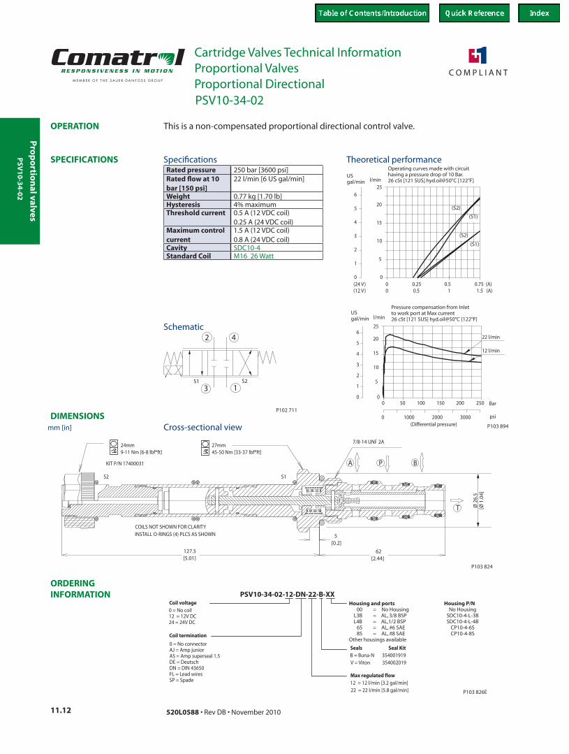
Operating curves made with circuithaving a pressure drop of 10 Bar.26 cSt [121 SUS] hyd.oil@50°C [122°F]
(S2)
(S1)
00
0.25 0.5 0.75 (A)
5
10
15
20
25l/min
0 0.5 1 1.5 (A)(24 V)(12 V)
0
USgal/min
5
4
3
2
1
6
Pressure compensation from Inletto work port at Max current26 cSt [121 SUS] hyd.oil@50°C [122°F]
Bar250
l/min
25
20
15
10
5
200150100500
0
(Differential pressure)300020000 1000 psi
22 l/min
12 l/min
0
USgal/min
5
4
3
2
1
6
(S1)
(S2)
P103 894E
P102 711
3 1
42
S2S1
S1S2
24mm9-11 Nm [6-8 lbf*ft]
KIT P/N 17400031
45-50 Nm [33-37 lbf*ft]27mm
7/8-14 UNF 2A
COILS NOT SHOWN FOR CLARITYINSTALL O-RINGS (4) PLCS AS SHOWN
A P B
T
5[0.2]
127.5[5.01]
62[2.44]
P103 824
Ø 2
6.5
[Ø 1
.04]
Max regulated flow12 = 12 l/min [3.2 gal/min]22 = 22 l/min [5.8 gal/min]
Coil termination
0 = No connectorAJ = Amp juniorAS = Amp superseal 1.5DE = DeutschDN = DIN 43650FL = Lead wiresSP = Spade
PSV10-34-02-12-DN-22-B-XX
Seals Seal KitB = Buna-N 354001919V = Viton 354002019
Coil voltage0 = No coil12 = 12V DC24 = 24V DC
P103 826E
Housing and ports Housing P/N00 = No Housing No Housing
L3B = AL, 3/8 BSP SDC10-4-L-3BL4B = AL,1/2 BSP SDC10-4-L-4B
6S = AL, #6 SAE CP10-4-6S8S = AL, #8 SAE CP10-4-8S
Other housings available
This is a non-compensated proportional directional control valve.
Rated pressure 250 bar [3600 psi]Rated flow at 10 bar [150 psi]
22 l/min [6 US gal/min]
Weight 0.77 kg [1.70 lb]Hysteresis 4% maximumThreshold current 0.5 A (12 VDC coil)
0.25 A (24 VDC coil)Maximum control current
1.5 A (12 VDC coil) 0.8 A (24 VDC coil)
Cavity SDC10-4Standard Coil M16 26 Watt
Theoretical performance
Schematic
Cross-sectional view
Specifications
PSV10-34-02
mm [in]
Proportional Directional
PSV
10
-34
-02
Pro
po
rtio
nal
val
ves
Cartridge Valves Technical InformationProportional Valves
11.13520L0588 • Rev DB • November 2010
ORDERING INFORMATION
SPECIFICATIONS
DIMENSIONS
OPERATION
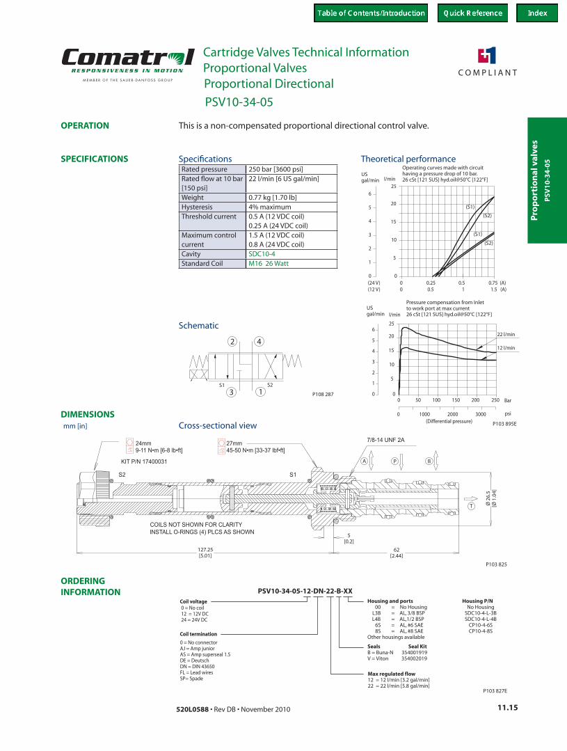
154 SUS (33 cSt) hyd. oil @ 100° F (38° C)
51.3
gpm L/min
Flo
w
50Loop pressure drop (P A B T)
725
bar
psi
0
10
15
20
25
30
35
2.6
4
5.3
6.6
7.9
9.2
100 150 200 250 300 350
1450 2176 2901 3626 4351 5076
154 SUS (33 cSt) hyd. oil @ 100° F (38° C)at 10 bar [145 psi] pressure drop
51
gpm L/min
Flo
w
0.40
10
15
20
25
30
3
4
5
7
8
0.8 1.2 1.6 2 2.4
Code = 30
Code = 15
2.4 A (12 V coil)
1.9 A (12 V coil)
1.4)
A V c(12 oil
Current, Amps (with 12 VDC coil)
P102 939E
P T
A B
P102 711E
Ø 45.7[1.80]
215.9[8.50]
P102 710
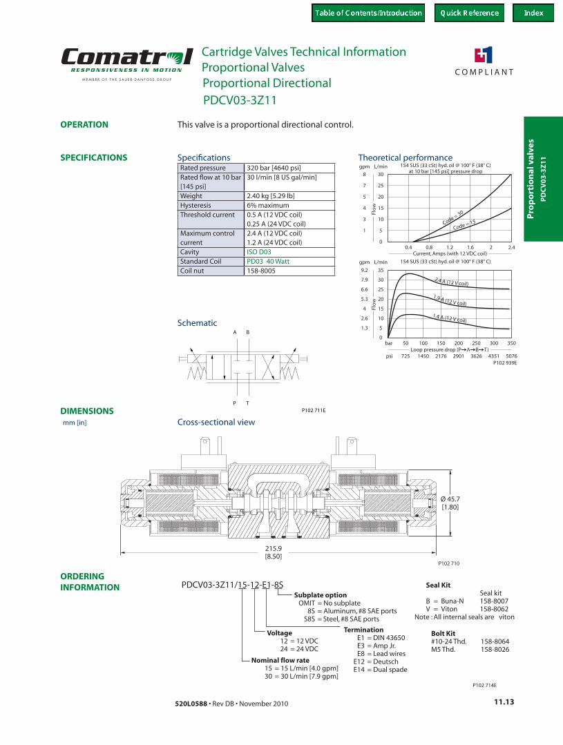
PDCV03-3Z11/15-12-E1-8S
Nominal flow rate15 = 15 L/min [4.0 gpm]30 = 30 L/min [7.9 gpm]
Voltage12 = 12 VDC24 = 24 VDC
TerminationE1 = DIN 43650E3 = Amp Jr.E8 = Lead wires
E12 = DeutschE14 = Dual spade
Subplate optionOMIT = No subplate
8S = Aluminum, #8 SAE portsS8S = Steel, #8 SAE ports
P102 714E
Seal KitSeal kit
B = Buna-N 158-8007V = Viton 158-8062
Note : All internal seals are viton
Bolt Kit#10-24 Thd. 158-8064M5 Thd. 158-8026
This valve is a proportional directional control.
Rated pressure 320 bar [4640 psi]Rated flow at 10 bar [145 psi]
30 l/min [8 US gal/min]
Weight 2.40 kg [5.29 lb]Hysteresis 6% maximumThreshold current 0.5 A (12 VDC coil)
0.25 A (24 VDC coil)Maximum control current
2.4 A (12 VDC coil) 1.2 A (24 VDC coil)
Cavity ISO D03Standard Coil PD03 40 WattCoil nut 158-8005
Theoretical performance
Schematic
Cross-sectional view
Specifications
PDCV03-3Z11
mm [in]
Proportional Directional
PD
CV
03
-3Z
11
Pro
po
rtion
al valves
Cartridge Valves Technical InformationProportional Valves
11.14 520L0588 • Rev DB • November 2010
ORDERING INFORMATION
SPECIFICATIONS
DIMENSIONS
OPERATION
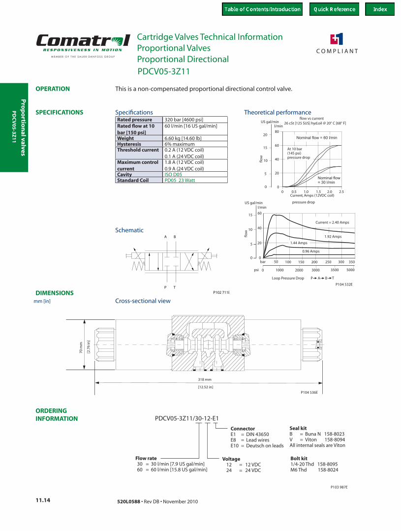
3000
250200
10
20
20
40
60
2.5
80
15
2.00
5
l/min
01.51.00.50
300
5000
bar
3500
40
6015
10
0
5 20
0
20000
150
psi
US gal/min
pressure drop
26 cSt [125 SUS] hyd.oil @ 20° C [68° F]
flow
flow
flow vs current
Current, Amps (12VDC coil)
At 10 bar(145 psi)pressure drop
P104 532E
Nominal flow = 60 l/min
Nominal flow
= 30 l/min
Current = 2.40 Amps
l/minUS gal/min
100 350
Loop Pressure Drop P A B T
1.92 Amps
1.44 Amps
0.96 Amps
50
1000
P T
A B
P102 711E
318 mm
[12.52 in]
70 m
m
[2.7
6 in
]
P104 536E
PDCV05-3Z11/30-12-E1
P103 987E
Voltage12 = 12 VDC24 = 24 VDC
ConnectorE1 = DIN 43650E8 = Lead wiresE10 = Deutsch on leads
Flow rate30 = 30 l/min [7.9 US gal/min]60 = 60 l/min [15.8 US gal/min]
Seal kitB = Buna N 158-8023V = Viton 94All internal seals are Viton
158-80
Bolt kit1/4-20 Thd 158-8095M6 Thd 158-8024
This is a non-compensated proportional directional control valve.
Rated pressure 320 bar [4600 psi]Rated flow at 10 bar [150 psi]
60 l/min [16 US gal/min]
Weight 6.60 kg [14.60 lb]Hysteresis 6% maximumThreshold current 0.2 A (12 VDC coil)
0.1 A (24 VDC coil)Maximum control current
1.8 A (12 VDC coil) 0.9 A (24 VDC coil)
Cavity ISO D05Standard Coil PD05 23 Watt
Theoretical performance
Schematic
Cross-sectional view
Specifications
PDCV05-3Z11
mm [in]
Proportional Directional
PD
CV
05
-3Z
11
Pro
po
rtio
nal
val
ves
Cartridge Valves Technical InformationProportional Valves
11.15520L0588 • Rev DB • November 2010
ORDERING INFORMATION
SPECIFICATIONS
DIMENSIONS
OPERATION
Operating curves made with circuithaving a pressure drop of 10 bar.26 cSt [121 SUS] hyd.oil@50°C [122°F]
(S1)
(S2)
6
1
2
3
4
5
USgal/min
0
12 l/min
22 l/min
psi10000 2000 3000(Differential pressure)
00
50 100 150 200
5
10
15
20
25
l/min
250 Bar
Pressure compensation from Inletto work port at max current26 cSt [121 SUS] hyd.oil@50°C [122°F]
6
1
2
3
4
5
USgal/min
0
(12 V)(24 V)
1.5 (A)10.50
l/min25
20
15
10
5
0.75 (A)0.50.250
0
(S2)
(S1)
P103 895E
P108 2873 1
42
S2S1
P103 825
A P B
T
127.25[5.01]
5[0.2]
62[2.44]
Ø 2
6.5
[Ø 1
.04]
Max regulated flow12 = 12 l/min [3.2 gal/min]22 = 22 l/min [5.8 gal/min]
PSV10-34-05-12-DN-22-B-XX
Seals Seal KitB = Buna-N 354001919V = Viton 354002019
P103 827E
Coil termination
0 = No connectorAJ = Amp juniorAS = Amp superseal 1.5DE = DeutschDN = DIN 43650FL = Lead wiresSP= Spade
Coil voltage0 = No coil12 = 12V DC24 = 24V DC
Housing and ports Housing P/N00 = No Housing No Housing
L3B = AL, 3/8 BSP SDC10-4-L-3BL4B = AL,1/2 BSP SDC10-4-L-4B
6S = AL, #6 SAE CP10-4-6S8S = AL, #8 SAE CP10-4-8S
Other housings available
This is a non-compensated proportional directional control valve.
Rated pressure 250 bar [3600 psi]Rated flow at 10 bar [150 psi]
22 l/min [6 US gal/min]
Weight 0.77 kg [1.70 lb]Hysteresis 4% maximumThreshold current 0.5 A (12 VDC coil)
0.25 A (24 VDC coil)Maximum control current
1.5 A (12 VDC coil) 0.8 A (24 VDC coil)
Cavity SDC10-4Standard Coil M16 26 Watt
Theoretical performance
Schematic
Cross-sectional view
Specifications
PSV10-34-05
mm [in]
Proportional Directional
PSV
10
-34
-05
Pro
po
rtion
al valves
Cartridge Valves Technical InformationProportional Valves
11.16 520L0588 • Rev DB • November 2010
ORDERING INFORMATION
SPECIFICATIONS
DIMENSIONS
OPERATION
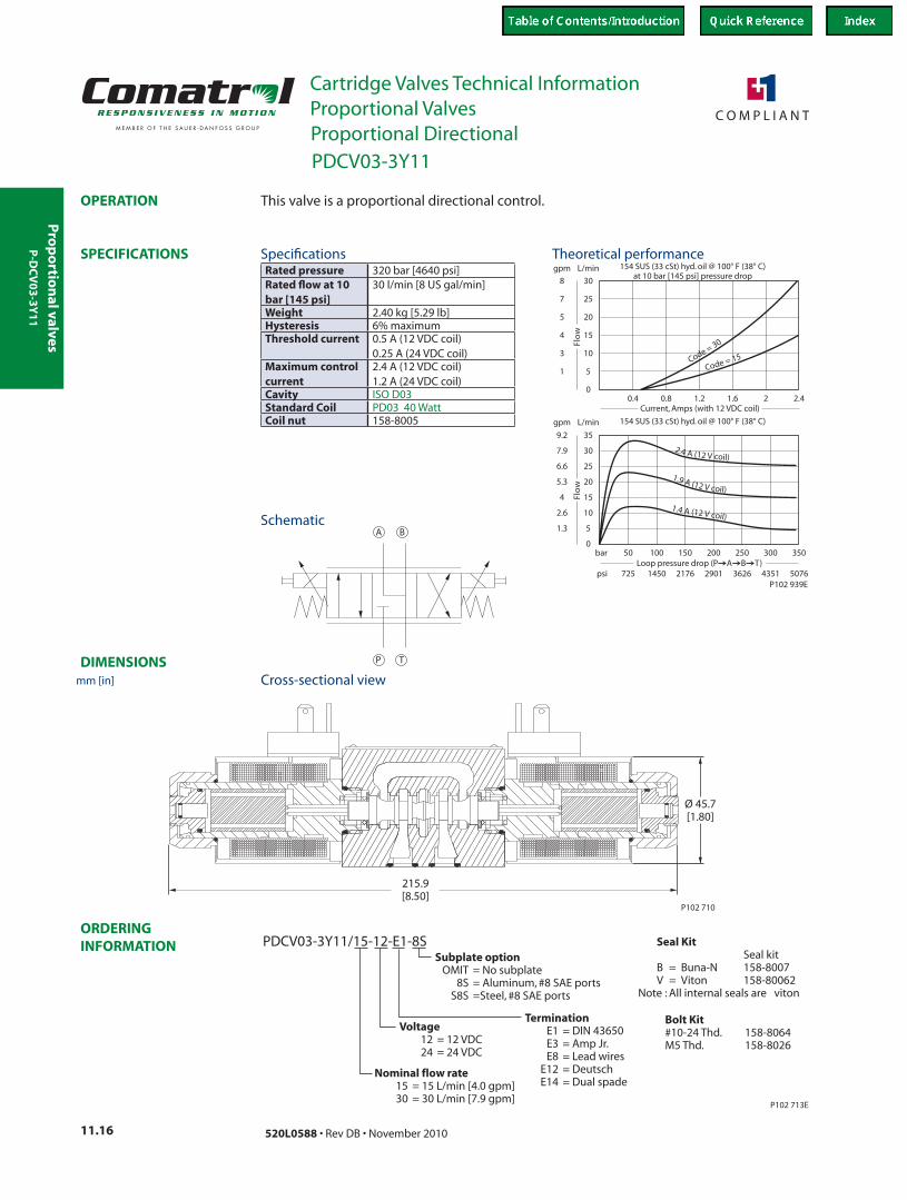
154 SUS (33 cSt) hyd. oil @ 100° F (38° C)
51.3
gpm L/min
Flo
w
50Loop pressure drop (P A B T)
725
bar
psi
0
10
15
20
25
30
35
2.6
4
5.3
6.6
7.9
9.2
100 150 200 250 300 350
1450 2176 2901 3626 4351 5076
154 SUS (33 cSt) hyd. oil @ 100° F (38° C)at 10 bar [145 psi] pressure drop
51
gpm L/min
Flo
w
0.40
10
15
20
25
30
3
4
5
7
8
0.8 1.2 1.6 2 2.4
Code = 30
Code = 15
2.4 A (12 V coil)
1.9 A (12 V coil)
1.4)
A V c(12 oil
Current, Amps (with 12 VDC coil)
P102 939E
TP
A B
Ø 45.7[1.80]
215.9[8.50]
P102 710
PDCV03-3Y11/15-12-E1-8S
Nominal flow rate15 = 15 L/min [4.0 gpm]30 = 30 L/min [7.9 gpm]
Voltage12 = 12 VDC24 = 24 VDC
TerminationE1 = DIN 43650E3 = Amp Jr.E8 = Lead wires
E12 = DeutschE14 = Dual spade
Subplate optionOMIT = No subplate
8S = Aluminum, #8 SAE portsS8S =Steel, #8 SAE ports
P102 713E
Seal KitSeal kit
B = Buna-N 158-8007V = Viton 158-80062
Note : All internal seals are viton
Bolt Kit#10-24 Thd. 158-8064M5 Thd. 158-8026
This valve is a proportional directional control.
Rated pressure 320 bar [4640 psi]Rated flow at 10 bar [145 psi]
30 l/min [8 US gal/min]
Weight 2.40 kg [5.29 lb]Hysteresis 6% maximumThreshold current 0.5 A (12 VDC coil)
0.25 A (24 VDC coil)Maximum control current
2.4 A (12 VDC coil) 1.2 A (24 VDC coil)
Cavity ISO D03Standard Coil PD03 40 WattCoil nut 158-8005
Theoretical performance
Schematic
Cross-sectional view
Specifications
P-D
CV
03
-3Y
11
PDCV03-3Y11
mm [in]
Proportional Directional
Pro
po
rtio
nal
val
ves
Cartridge Valves Technical InformationProportional Valves
11.17520L0588 • Rev DB • November 2010
ORDERING INFORMATION
SPECIFICATIONS
DIMENSIONS
OPERATION
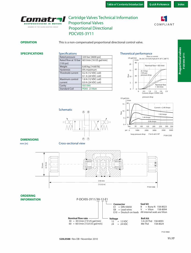
3000
250200
10
20
20
40
60
2.5
80
15
2.00
5
l/min
01.51.00.50
300
5000
bar
3500
40
6015
10
0
5 20
0
20000
150
psi
US gal/min
pressure drop
26 cSt [125 SUS] hyd.oil @ 20° C [68° F]
flow
flow
flow vs current
Current, Amps (12VDC coil)
At 10 bar(145 psi)pressure drop
P104 533E
Nominal flow = 60 l/min
Nominal flow
= 30 l/min
Current = 2.40 Amps
l/minUS gal/min
100 350
loop pressure drop P A B T
1.92 Amps
1.44 Amps
0.96 Amps
50
1000
TP
A B
318 mm
[12.52 in]
70 m
m
[2.7
6 in
]
P104 536E
P-DCV05-3Y11/30-12-E1
P103 986E
Voltage12 = 12 VDC24 = 24 VDC
ConnectorE1 = DIN 43650E8 = Lead wiresE10 = Deutsch on leads
Nominal flow rate30 = 30 l/min [7.9 US gal/min]60 = 60 l/min [15.8 US gal/min]
Seal kitB = Buna N 158-8023V = Viton 94All internal seals are Viton
158-80
Bolt kit1/4-20 Thd 158-8093M6 Thd 158-8024
This is a non-compensated proportional directional control valve.
Rated pressure 320 bar [4600 psi]Rated flow at 10 bar [150 psi]
60 l/min [16 US gal/min]
Weight 6.60 kg [14.60 lb]Hysteresis 6% maximumThreshold current 0.2 A (12 VDC coil)
0.1 A (24 VDC coil)Maximum control current
1.8 A (12 VDC coil) 0.9 A (24 VDC coil)
Cavity ISO D05Standard Coil PD05 23 Watt
Theoretical performance
Schematic
Cross-sectional view
Specifications
P-D
CV
05
-3Y
11
PDCV05-3Y11
mm [in]
Proportional Directional
Pro
po
rtion
al valves
Cartridge Valves Technical InformationProportional Valves
11.18 520L0588 • Rev DB • November 2010
ORDERING INFORMATION
SPECIFICATIONS
DIMENSIONS
OPERATION
P102 940E
0.0 0.2 2.0
0
2
4
6
8
10
12
14
0.5
0.0
1.1
1.6
2.1
2.6
3.2
3.7
Current, Amps (with 12 VDC coil)
gal/min l/min
8H
6H
4H
2H
0
2
4
6
8
10
12
0 2 4 6 8 10 12 14 16 18
4.84.23.73.22.62.11.61.00.50
174
145
116
87
58
29
0
L/min
US gal/min
barpsi
8H
33 cSt [154 SUS] hyd.oil @ 38°C [100° F]
at 5.5 bar [80 psi] pressure drop
Flow vs. Current
33 cSt [154 SUS] hyd.oil @ 38°C [100° F]
At Maximum Control Current
Pressure Drop vs. Flow
6H4H
0.6 0.8 1.21.0 1.4 1.81.60.4
2
1
P104 832
P102 704E
5 N·m MAX.
[44 lbf·in]
86.1 [3.39]
3/4-16 UNF
7/8 HEX
27-34 N·m
[20-25 lbf·ft]
COIL NOT SHOWN FOR CLARITY
INSTALL O-RING AS SHOWN
2
P102 654E
SealsSeal kits
U = Urethane 120591
CP518-PNC-U-6S-2H-24-DE
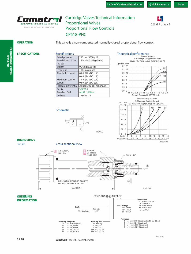
Flow code2H = 5 l/min [1.3 US gal/min] at 5.5 bar [80 psi]4H = 9 l/min [2.4 US gal/min]6H = 11 l/min [2.9 US gal/min]8H = 13 l/min [3.4 US gal/min]
Termination00 = No connector
FL = Lead wires
DE = DeutschDN = DIN 43650Voltage
00 = No coil12 = 12 VDC24 = 24 VDC
Housing and ports Housing P/N0 = Cartridge only No Housing
4S = AL, #4 SAE CP08-2-4S6S = AL, #6 SAE CP08-2-6S2B = AL,1/4 BSP SDC08-2-DG-2B3B = AL, 3/8 BSP SDC08-2-DG-3B
AJ = AMP Jr
This valve is a non-compensated, normally-closed, proportional flow control.
Rated pressure 210 bar [3000 psi]Rated flow at 6 bar [80 psi]
12 l/min [3 US gal/min]
Weight 0.36 kg [0.80 lb]Hysteresis 10% maximumThreshold current 0.8 A (12 VDC coil)
0.4 A (24 VDC coil)Maximum control current
1.8 A (12 VDC coil) 0.9 A (24 VDC coil)
Pressure differential 21 bar [300 psi] maximumCavity SDC08-2Standard Coil M19P 22 WattCoil nut 173802114
Theoretical performance
Schematic
Cross-sectional view
SpecificationsCP
51
8-P
NC
CP518-PNC
mm [in]
Proportional Flow Controls
Pro
po
rtio
nal
val
ves
Cartridge Valves Technical InformationProportional Valves
11.19520L0588 • Rev DB • November 2010
ORDERING INFORMATION
SPECIFICATIONS
DIMENSIONS
OPERATION
2
1
P104 832
86.80[3.42]
32.00[1.26]
Ø26
.50
[Ø1.
04]
3-5 Nm [2.2-3.7bf•ft]
COIL NOT SHOWN FOR CLARITY
1
2
COIL NUT KIT P/N 173802188
26mm45-50 Nm [33-37 lbf•ft]27
7/8-14 UNF 2A
P104 833
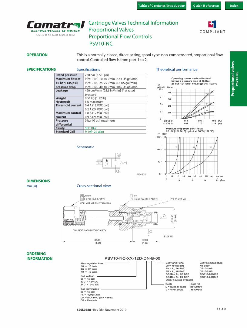
This is a normally-closed, direct-acting, spool-type, non-compensated, proportional flow-control. Controlled flow is from port 1 to 2.
Rated pressure 260 bar [3770 psi]Maximum flow at 10 bar [145 psi] pressure drop
PSV10-NC-10: 10 l/min [2.64 US gal/min]PSV10-NC-25: 25 l/min [6.6 US gal/min]PSV10-NC-40: 40 l/min [10.6 US gal/min]
Leakage 420 cm³/min [25.6 in³/min] @ at rated pressure
Weight 0.51 kg [1.12 lb]Hysteresis 5% maximumThreshold current 0.4 A (12 VDC coil)
0.2 A (24 VDC coil)Maximum control current
1.8 A (12 VDC coil) 0.9 A (24 VDC coil)
Pressure differential
0 bar [0 psi] maximum
Cavity SDC10-2Standard Coil M19P 22 Watt
Theoretical performance
Schematic
Cross-sectional view
Specifications
PSV
10
-NC
PSV10-NC
mm [in]
Proportional Flow Controls

Pro
po
rtion
al valves
Cartridge Valves Technical InformationProportional Valves
11.20 520L0588 • Rev DB • November 2010
ORDERING INFORMATION
SPECIFICATIONS
DIMENSIONS
OPERATION
2
1
P104 832
94.50[3.72]
45.00[1.77]
Ø31
.50
[Ø1.
24]
1-1/16-12 UN68-75 Nm [50-55 lbf*ft]32mm27mm
9-11 Nm [6-8 lbf*ft]
1
2
Coil Nut P/N 17380531
COIL NOT SHOWN FOR CLARITY
P104 841
This is a normally-closed, direct-acting, spool-type, non-compensated, proportional flow-control. Controlled flow is from port 1 to 2.
Rated pressure 260 bar [3770 psi]Maximum flow at 10 bar [145 psi]
PSV12-NC-60: 60 l/min [15.85 US gal/min]PSV12-NC-80: 80 l/min [21.13 US gal/min]
Leakage 420 cm³/min [25.6 in³/min] @ at rated pressure
Weight 0.76 kg [1.68 lb]Hysteresis 5% maximumThreshold current 0.5 A (12 VDC coil)
0.25 A (24 VDC coil)Maximum control current
1.8 A (12 VDC coil) 0.9 A (24 VDC coil)
Pressure differential 0 bar [0 psi] maximumCavity SDC12-2Standard Coil D14E(35W) 35 Watt
Theoretical performance
Schematic
Cross-sectional view
SpecificationsPSV
12
-NC
PSV12-NC
mm [in]
Proportional Flow Controls
Pro
po
rtio
nal
val
ves
Cartridge Valves Technical InformationProportional Valves
11.21520L0588 • Rev DB • November 2010
ORDERING INFORMATION
SPECIFICATIONS
DIMENSIONS
OPERATION
Operating curves made with circuithaving a pressure drop of 10 bar.26 cSt [121 SUS] hyd.oil@50°C [122°F]
24
4
8
12
16
20
USgal/min
0
(12 V)(24 V)
1.8 (A)1.20.60
l/min100
80
60
40
20
0.9 (A)0.60.30
0
0 2010 US gal/min
barpsi
120
80
8060 l/min.4020
0
403
6
9
0
0
Pressure drop
26 cSt [121 SUS] hyd.oil at 50°C [122°F]
100P104 849
2
1
P104 832
97.30[3.83]
3.60[0.14]
47.10[1.85]
Ø37
.80
[Ø1.
49]
38mm122-136 Nm [90-100 lbf*ft]
1 5/16-12 UN
1
2
9-11 Nm [6-8 lbf*ft]27mm
COIL NOT SHOWN FOR CLARITY
Coil Nut P/N 17380531
P104 848
Body Nomencl.No BodySDC16-2-DG-6BSDC16-2-DG-8BCP16-2-12SCP16-2-16S
Body and Ports00 = No housingDG6B = Al, 3/4 BSPDG8B = Al, 1 BSP12S = Al, #12 SAE16S = Al, #16 SAEOther housing available
Max regulated flow100 = 100 l/min
Coil voltage00 = No coil12D = 12V DC24D = 24V DC
Seals Seal KitB = Buna-N seals 354008719V = Viton 354008819
PSV16-NC-100-12D-DN-B-00
Coil termination00 = No coilFL = Flying LeadDN = ISO 4400 (DIN 43650)DE = DeutschAJ = Amp JuniorAS = Amp Superseal
P104 850
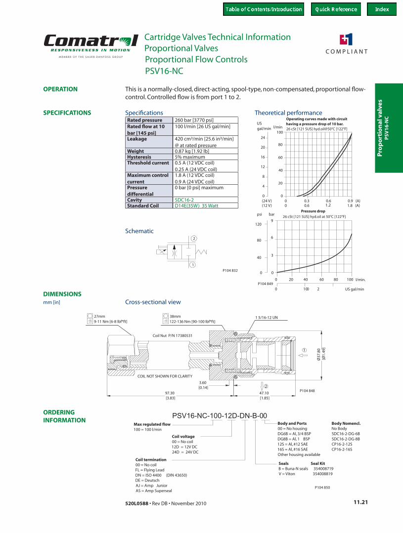
This is a normally-closed, direct-acting, spool-type, non-compensated, proportional flow-control. Controlled flow is from port 1 to 2.
Rated pressure 260 bar [3770 psi]Rated flow at 10 bar [145 psi]
100 l/min [26 US gal/min]
Leakage 420 cm³/min [25.6 in³/min] @ at rated pressure
Weight 0.87 kg [1.92 lb]Hysteresis 5% maximumThreshold current 0.5 A (12 VDC coil)
0.25 A (24 VDC coil)Maximum control current
1.8 A (12 VDC coil) 0.9 A (24 VDC coil)
Pressure differential
0 bar [0 psi] maximum
Cavity SDC16-2Standard Coil D14E(35W) 35 Watt
Theoretical performance
Schematic
Cross-sectional view
Specifications
PSV
16
-NC
PSV16-NC
mm [in]
Proportional Flow Controls
Pro
po
rtion
al valves
Cartridge Valves Technical InformationProportional Valves
11.22 520L0588 • Rev DB • November 2010
ORDERING INFORMATION
SPECIFICATIONS
DIMENSIONS
OPERATION
50 bar
35 bar
20 bar
00
0.3 0.9 (A)
25
75
100
125l/min
0 0.6 1.8 (A)(24 V)(12 V)
0
USgal/min
25
20
15
10
5
30
26 cSt [121 SUS] hyd.oil@50°C [122°F]
50
0.61.2
5
200
400
12020
10 US gal/min
barpsi
800
600
8060 l/min.40
0
20
40
60
0
0
Pressure drop26 cSt [121 SUS] hyd.oil at 50°C [122°F]
100
Operating Curves
P104 85620150 25
1
2
P104 854
107.12[4.22]
31.90[1.26]
Ø26
.50
[Ø1.
04]
7/8-14 UNF 2A45-50 Nm [33-37 lbf*ft]27
COIL NUT KIT P/N 173802188
3-5 Nm [2.2-3.7bf*ft]26mm
COIL NOT SHOWN FOR CLARITY
1
2
P104 855
Body NomenclatureNo BodyCP10-2-6SCP10-2-8SSDC10-2-DG3BSDC10-2-DG4B
Coil termination00 = No coilFL = Flying LeadDN = ISO 4400 (DIN 43650)DE = Deutsch
PSVP10-NCR-12D-DN-B-00Body and Ports00 = No housing6S = Al, #6 SAE8S = Al, #8 SAEDG3B = Al, 3/8 BSPDG4B = Al, 1/2 BSPOther housing available
Seals Seal KitB = Buna-N seals 354004019V = Viton seals 354003419
Coil voltage00 = No coil12D = 12V DC24D = 24V DC
P104 857AJ = AMP Jr
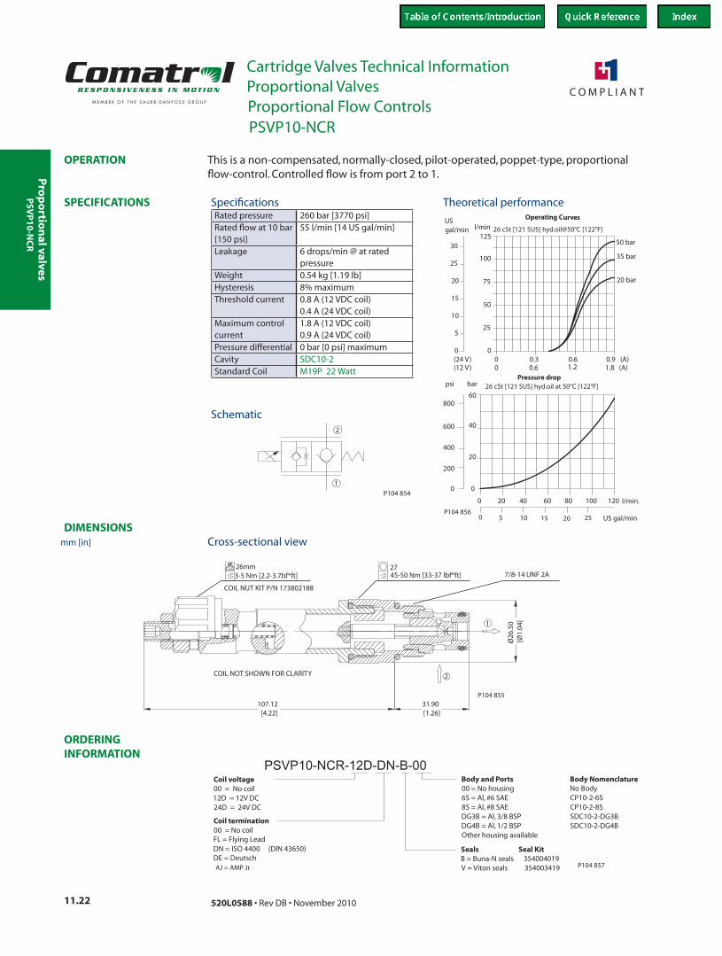
This is a non-compensated, normally-closed, pilot-operated, poppet-type, proportional flow-control. Controlled flow is from port 2 to 1.
Rated pressure 260 bar [3770 psi]Rated flow at 10 bar [150 psi]
55 l/min [14 US gal/min]
Leakage 6 drops/min @ at rated pressure
Weight 0.54 kg [1.19 lb]Hysteresis 8% maximumThreshold current 0.8 A (12 VDC coil)
0.4 A (24 VDC coil)Maximum control current
1.8 A (12 VDC coil) 0.9 A (24 VDC coil)
Pressure differential 0 bar [0 psi] maximumCavity SDC10-2Standard Coil M19P 22 Watt
Theoretical performance
Schematic
Cross-sectional view
Specifications
PSVP10-NCR
mm [in]
Proportional Flow Controls
PSV
P1
0-N
CR

Pro
po
rtio
nal
val
ves
Cartridge Valves Technical InformationProportional Valves
11.23520L0588 • Rev DB • November 2010
ORDERING INFORMATION
SPECIFICATIONS
DIMENSIONS
OPERATION
125
Pressure drop26 cSt [121 SUS] hyd.oil at 50°C [122°F]
0
0
60
40
20
0
50 l/min.75 100
600
800
psi bar
US gal/min15 300
25 150
400
200
50 bar
35 bar
20 bar
1.20.6
60
Operating Cur ves26 cSt [121 SUS] hyd.oil@50°C [122°F]
36
6
12
18
24
30
USgal/min
0
(12 V)(24 V)
1.8 (A)0.60
l/min150
120
90
30
0.9 (A)0.30
0
P104 863
1
2
P104 854
Ø31
.5[
1.24
]Ø
45[1.77]
105.52[4.15]
1
2
COIL NUT KIT P/N 173802188
3-5 Nm [2.2-3.7bf*ft]26mm
68-75 Nm [50-55 lbf*ft]32 mm
1-1/16-12 UN
COIL NOT SHOWN FOR CLARITY
P104 862
Coil voltage00 = No coil12D = 12V DC24D = 24V DC
Seals Seal KitB = Buna-N seals 354008319V = Viton 354008419
Body and Ports00 = No housing10S = Al, #10 SAE12S = Al, #12 SAE4B = Al, 1/2 BSP6B = Al, 3/4 BSPOther housing available
PSVP12-NCR-12D-DN-B-00
Coil termination00 = No coilFL = Flying LeadDN = ISO 4400 (DIN 43650)DE = Deutsch
Body Nomencl.No BodyCP12-3-10SCP12-3-12SCP12-3-4BCP12-3-6B
P104 864
AJ = AMP Jr
This is a non-compensated, normally-closed, pilot-operated, poppet-type, proportional flow-control. Controlled flow is from port 2 to 1.
Rated pressure 260 bar [3770 psi]Rated flow at 10 bar [150 psi]
70 l/min [18 US gal/min]
Leakage 6 drops/min @ at rated pressure
Weight 0.60 kg [1.32 lb]Hysteresis 8% maximumPressure differential
0 bar [0 psi] maximum
Cavity SDC12-2Standard Coil M19P 22 Watt
Theoretical performance
Schematic
Cross-sectional view
Specifications
PSVP12-NCR
mm [in]
Proportional Flow Controls
PSV
P1
2-N
CR
Pro
po
rtion
al valves
Cartridge Valves Technical InformationProportional Valves
11.24 520L0588 • Rev DB • November 2010
ORDERING INFORMATION
SPECIFICATIONS
DIMENSIONS
OPERATION
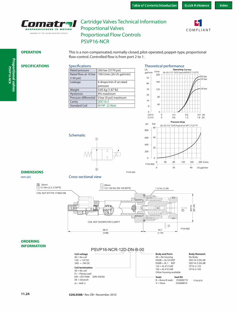
00
0.3 0.9 (A)
40
120
160
200l/min
0 0.6 1.8 (A)(24 V)(12 V)
0
USgal/min
40
32
24
16
8
52
Operating Curves26 cSt [121 SUS] hyd.oil@50°C [122°F]
80
0.61.2
50 bar35 bar
20 bar
200
400
20040
20 US gal/min
barpsi
800
600
120 l/min.80
0
20
40
60
0
0
Pressure drop
26 cSt [121 SUS] hyd.oil at 50°C [122 °F]
160
400
P104 869
2
1
P102 660
98.51[3.88]
44.7[1.76]
Ø37
.8[Ø
1.49
]COIL NUT KIT P/N 173802188
26mm3-5 Nm [2.2-3.7bf*ft] 1 5/16-12 UN
38mm122-136 Nm [90-100 lbf*ft]
2
1
COIL NOT SHOWN FOR CLARITY
P104 868
PSVP16-NCR-12D-DN-B-00Coil voltage00 = No coil12D = 12V DC24D = 24V DC
Seals Seal KitB = Buna-N seals 354008719V = Viton 354008819
Body and Ports00 = No housingDG6B = Al, 3/4 BSPDG8B = Al, 1 BSP12S = Al, #12 SAE16S = Al, #16 SAEOther housing available
Coil termination00 = No coilFL = Flying LeadDN = ISO 4400 (DIN 43650)DE = Deutsch
Body Nomencl.No BodySDC16-2-DG-6BSDC16-2-DG-8BCP16-2-12SCP16-2-16S
P104 870AJ = AMP Jr
This is a non-compensated, normally-closed, pilot-operated, poppet-type, proportional flow-control. Controlled flow is from port 2 to 1.
Rated pressure 260 bar [3770 psi]Rated flow at 10 bar [150 psi]
100 l/min [26 US gal/min]
Leakage 6 drops/min @ at rated pressure
Weight 0.85 kg [1.87 lb]Hysteresis 8% maximumPressure differential 0 bar [0 psi] maximumCavity SDC16-2Standard Coil M19P 22 Watt
Theoretical performance
Schematic
Cross-sectional view
Specifications
PSVP16-NCR
mm [in]
Proportional Flow Controls
PSV
P1
6-N
CR
Pro
po
rtio
nal
val
ves
Cartridge Valves Technical InformationProportional Valves
11.25520L0588 • Rev DB • November 2010
ORDERING INFORMATION
SPECIFICATIONS
DIMENSIONS
OPERATION
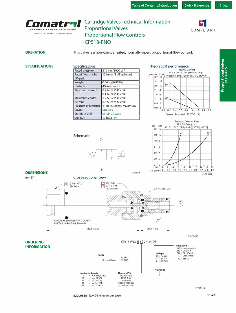
P102 699E
0.0 0.2 1.60
2
4
6
8
10
12
14
0.5
0.0
1.1
1.6
2.1
2.6
3.2
3.7
Current, Amps (with 12 VDC coil)
gal/min l/min
2H
0
2
4
6
8
10
12
0 2 4 6 8 10 12 14 16 184.84.23.73.22.62.11.61.00.50
174
145
116
87
58
29
0L/min
US gal/min
barpsi 33 cSt [154 SUS] hyd.oil @ 38°C [100° F]
Pressure Drop vs. Flow
2H 8H
Coil De-Energized
33 cSt [154 SUS] hyd.oil @ 38°C [100° F]at 5.5 bar [80 psi] pressure drop
Flow vs. Current
0.4 0.6 0.8 1.0 1.41.2
8H
2
1
P102 660
P102 703E
27.7 [1.09]86.1 [3.39]
3/4-16 UNF-2A
7/8 HEX
27-41 N·m
[20-30 lbf·ft]
5 N·m MAX.
[44 lbf·in]
COIL NOT SHOWN FOR CLARITY
INSTALL O-RING AS SHOWN
2
SealsSeal kits
U = Urethane 120591
CP518-PNO-U-6S-2H-24-DE
Flow code2H8H
P102 655E
Termination00 = No connector
FL = Lead wires
DE = DeutschDN = DIN 43650Voltage
00 = No coil12 = 12 VDC24 = 24 VDC
Housing and ports Housing P/N0 = Cartridge only No Housing
4S = AL, #4 SAE CP08-2-4S6S = AL, #6 SAE CP08-2-6S2B = AL,1/4 BSP SDC08-2-DG-2B3B = AL, 3/8 BSP SDC08-2-DG-3B
AJ = AMP Jr
This valve is a non-compensated, normally-open, proportional flow control.
Rated pressure 210 bar [3000 psi]Rated flow at 6 bar [80 psi]
12 l/min [3 US gal/min]
Weight 0.36 kg [0.80 lb]Hysteresis 4% maximumThreshold current 0.2 A (12 VDC coil)
0.1 A (24 VDC coil)Maximum control current
1.2 A (12 VDC coil) 0.6 A (24 VDC coil)
Pressure differential 21 bar [300 psi] maximumCavity SDC08-2Standard Coil M19P 22 WattCoil nut 173802114
Theoretical performance
Schematic
Cross-sectional view
Specifications
CP518-PNO
mm [in]
Proportional Flow Controls
CP
51
8-P
NO
Pro
po
rtion
al valves
Cartridge Valves Technical InformationProportional Valves
11.26 520L0588 • Rev DB • November 2010
ORDERING INFORMATION
SPECIFICATIONS
DIMENSIONS
OPERATION
2
1P104 836
86.80[3.42]
32.00[1.26]
26.5
0[1
.04]
2
1
COIL NOT SHOWN FOR CLARITY
26mm3-5 Nm [2.2-3.7bf*ft]
COIL NUT KIT P/N 173802188
2745-50 Nm [33-37 lbf*ft] 7/8-14 UNF 2A
P104 837
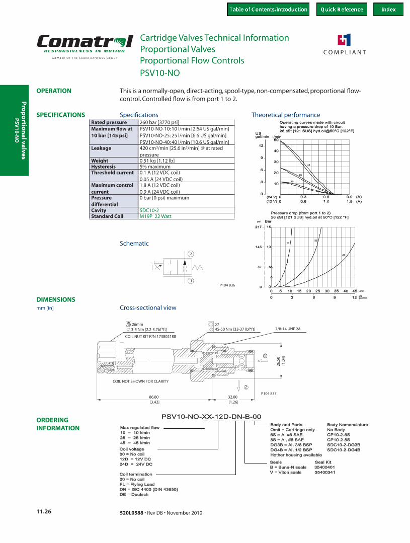
This is a normally-open, direct-acting, spool-type, non-compensated, proportional flow-control. Controlled flow is from port 1 to 2.
Rated pressure 260 bar [3770 psi]Maximum flow at 10 bar [145 psi]
PSV10-NO-10: 10 l/min [2.64 US gal/min]PSV10-NO-25: 25 l/min [6.6 US gal/min]PSV10-NO-40: 40 l/min [10.6 US gal/min]
Leakage 420 cm³/min [25.6 in³/min] @ at rated pressure
Weight 0.51 kg [1.12 lb]Hysteresis 5% maximumThreshold current 0.1 A (12 VDC coil)
0.05 A (24 VDC coil)Maximum control current
1.8 A (12 VDC coil) 0.9 A (24 VDC coil)
Pressure differential
0 bar [0 psi] maximum
Cavity SDC10-2Standard Coil M19P 22 Watt
Theoretical performance
Schematic
Cross-sectional view
Specifications
PSV10-NO
mm [in]
Proportional Flow Controls
PSV
10
-NO
Pro
po
rtio
nal
val
ves
Cartridge Valves Technical InformationProportional Valves
11.27520L0588 • Rev DB • November 2010
ORDERING INFORMATION
SPECIFICATIONS
DIMENSIONS
OPERATION
2
1P104 836
45.50[1.79]
4.00[0.16]
94.50[3.72]
Ø31
.50
[Ø1.
24]
Coil Nut P/N 17380531
2
1
27mm9-11 Nm [6-8 lbf*ft] 68-75 Nm [50-55 lbf*ft]
32mm1-1/16-12 UN
COIL NOT SHOWN FOR CLARITY
P104 845
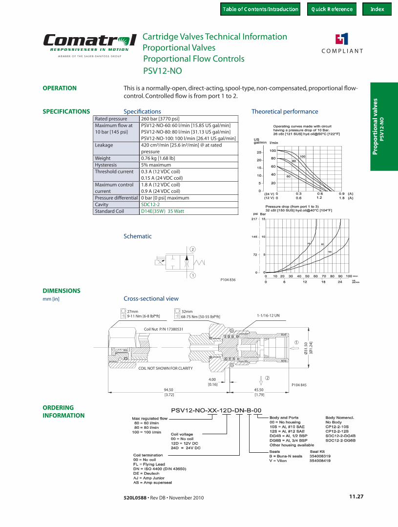
This is a normally-open, direct-acting, spool-type, non-compensated, proportional flow-control. Controlled flow is from port 1 to 2.
Rated pressure 260 bar [3770 psi]Maximum flow at 10 bar [145 psi]
PSV12-NO-60: 60 l/min [15.85 US gal/min]PSV12-NO-80: 80 l/min [31.13 US gal/min]PSV12-NO-100: 100 l/min [26.41 US gal/min]
Leakage 420 cm³/min [25.6 in³/min] @ at rated pressure
Weight 0.76 kg [1.68 lb]Hysteresis 5% maximumThreshold current 0.3 A (12 VDC coil)
0.15 A (24 VDC coil)Maximum control current
1.8 A (12 VDC coil) 0.9 A (24 VDC coil)
Pressure differential 0 bar [0 psi] maximumCavity SDC12-2Standard Coil D14E(35W) 35 Watt
Theoretical performance
Schematic
Cross-sectional view
Specifications
PSV12-NO
mm [in]
Proportional Flow Controls
PSV
12
-NO

Pro
po
rtion
al valves
Cartridge Valves Technical InformationProportional Valves
11.28 520L0588 • Rev DB • November 2010
ORDERING INFORMATION
SPECIFICATIONS
DIMENSIONS
OPERATION
200
400
12020
00
0.3 0.9 (A)
25
75
100
125l/min
0 0.6 1.8 (A)(24 V)(12 V)
0
USgal/min
25
20
15
10
5
30
26 cSt [121 SUS] hyd.oil@50°C [122°F]
50
0.61.2
barpsi
800
600
8060 l/min.40
0
20
40
60
0
0
Pressure drop26 cSt [121 SUS] hyd.oil at 50°C [122°F]
100
Operating Curves
50 bar
35 bar
20 bar
5 20150 2510 US gal/minP104 860
1
2
P104 858
31.9[1.26]
86.8[3.42]
Ø26
.5[Ø
1.04
]
7/8-14 UNF 2A45-50 Nm [33-37 lbf*ft]27
COIL NUT KIT P/N 173802188
3-5 Nm [2.2-3.7bf*ft]26mm
COIL NOT SHOWN FOR CLARITY2
1
P104 859
PSVP10-NOR-12D-DN-B-00Body NomenclatureNo BodyCP10-2-6SCP10-2-8SSDC10-2-DG3BSDC10-2-DG4B
Body and Ports00 = No housing6S = Al, #6 SAE8S = Al, #8 SAEDG3B = Al, 3/8 BSPDG4B = Al, 1/2 BSPOther housing available
Seals Seal KitB = Buna-N seals 354004019V = Viton seals 354003419
Coil voltage00 = No coil12D = 12V DC24D = 24V DC
Coil termination00 = No coilFL = Flying LeadDN = ISO 4400 (DIN 43650)DE = Deutsch
P104 861AJ = AMP Jr
This is a non-compensated, normally-open, pilot-operated, poppet-type, proportional flow-control. Controlled flow is from port 2 to 1.
Rated pressure 260 bar [3770 psi]Rated flow at 10 bar [2600150 psi]
45 l/min [12 US gal/min]
Leakage 6 drops/min @ at rated pressure
Weight 0.54 kg [1.19 lb]Hysteresis 8% maximumPressure differential
0 bar [0 psi] maximum
Cavity SDC10-2Standard Coil M19P 22 Watt
Theoretical performance
Schematic
Cross-sectional view
Specifications
PSVP10-NOR
mm [in]
Proportional Flow Controls
PSV
P1
0-N
OR
Pro
po
rtio
nal
val
ves
Cartridge Valves Technical InformationProportional Valves
11.29520L0588 • Rev DB • November 2010
ORDERING INFORMATION
SPECIFICATIONS
DIMENSIONS
OPERATION
125
Pressure drop26 cSt [121 SUS] hyd.oil at 50°C [122 °F]
0
0
60
40
20
0
50 l/min.75 100
600
800
psi bar
US gal/min15 300
25 150
400
200
1.20.6
60
Operating Curves26 cSt [121 SUS] hyd.oil@50°C [122°F]
36
6
12
18
24
30
USgal/min
0
(12 V)(24 V)
1.8 (A)0.60
l/min150
120
90
30
0.9 (A)0.30
0
50 bar
35 bar
20 bar
P104 866
1
2
P104 858
86.34[3.4]
44.91[1.77]
Ø31
.44
[Ø1.
24]
COIL NOT SHOWN FOR CLARITY
2
1
1-1/16-12 UN
COIL NUT KIT P/N 173802188
3-5 Nm [2.2-3.7bf*ft]26mm
68-75 Nm [50-55 lbf*ft]32 mm
P104 865
Body Nomencl.No BodyCP12-3-10SCP12-3-12SCP12-3-4BCP12-3-6B
Coil termination00 = No coilFL = Flying LeadDN = ISO 4400 (DIN 43650)DE = Deutsch
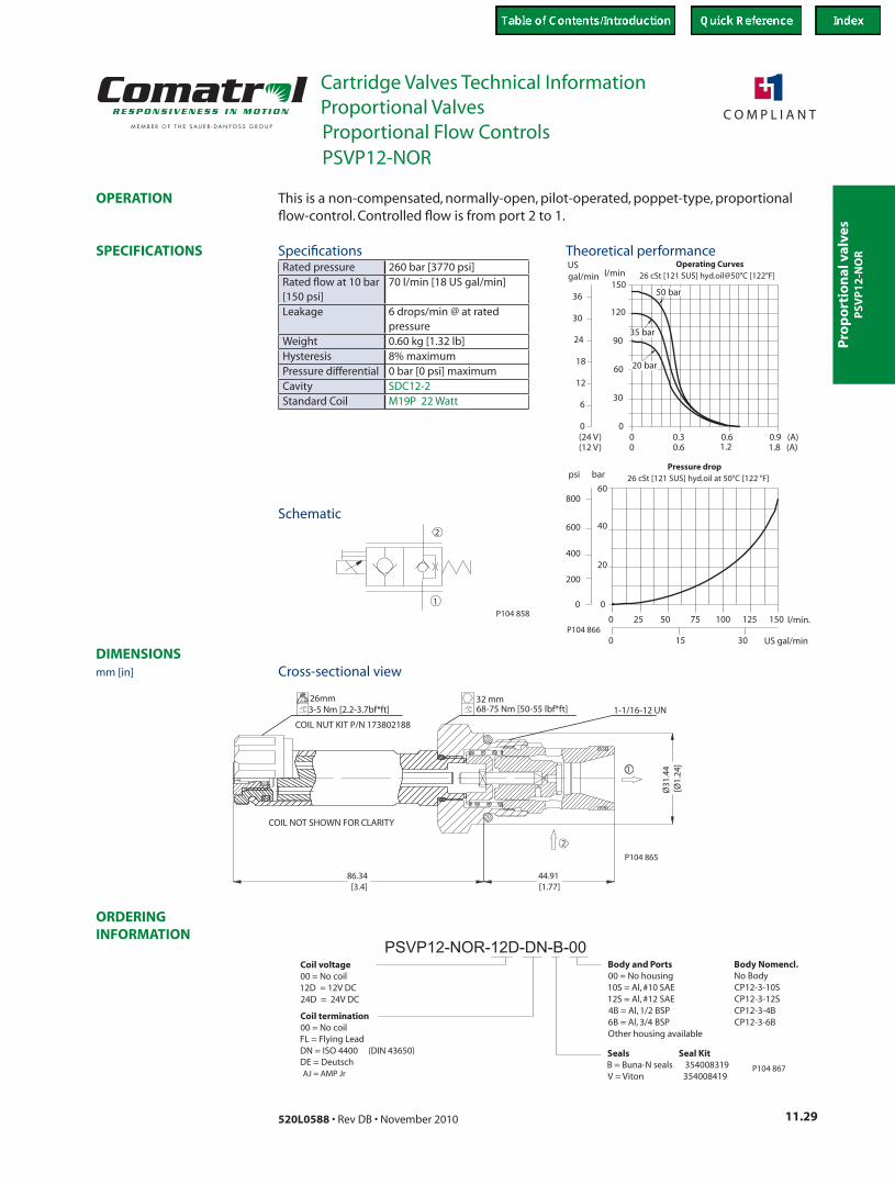
PSVP12-NOR-12D-DN-B-00Body and Ports00 = No housing10S = Al, #10 SAE12S = Al, #12 SAE4B = Al, 1/2 BSP6B = Al, 3/4 BSPOther housing available
Seals Seal KitB = Buna-N seals 354008319V = Viton 354008419
Coil voltage00 = No coil12D = 12V DC24D = 24V DC
P104 867AJ = AMP Jr
This is a non-compensated, normally-open, pilot-operated, poppet-type, proportional flow-control. Controlled flow is from port 2 to 1.
Rated pressure 260 bar [3770 psi]Rated flow at 10 bar [150 psi]
70 l/min [18 US gal/min]
Leakage 6 drops/min @ at rated pressure
Weight 0.60 kg [1.32 lb]Hysteresis 8% maximumPressure differential 0 bar [0 psi] maximumCavity SDC12-2Standard Coil M19P 22 Watt
Theoretical performance
Schematic
Cross-sectional view
Specifications
PSVP12-NOR
mm [in]
Proportional Flow Controls
PSV
P1
2-N
OR
Pro
po
rtion
al valves
Cartridge Valves Technical InformationProportional Valves
11.30 520L0588 • Rev DB • November 2010
ORDERING INFORMATION
SPECIFICATIONS
DIMENSIONS
OPERATION
00
0.3 0.9 (A)
40
120
160
200l/min
0 0.6 1.8 (A)(24 V)(12 V)
0
USgal/min
40
32
24
16
8
52
Operating Curves26 cSt [121 SUS] hyd.oil@50°C [122°F]
80
0.61.2
200
400
20040
20 US gal/min
barpsi
800
600
160120 l/min.80
0
20
40
60
0
0
Pressure drop26 cSt [121 SUS] hyd.oil at 50°C [122 °F]
400
50 bar
35 bar
20 bar
P104 872
1
2
P104 858
44.8[1.76]
Ø37
.8[Ø
1.49
]
89.3[3.52]
1
2
3-5 Nm [2.2-3.7bf*ft]26mm
COIL NUT KIT P/N 173802188
122-136 Nm [90-100 lbf*ft]38mm
1 5/16-12 UN
COIL NOT SHOWN FOR CLARITY
P104 871
Body Nomencl.No BodySDC16-2-DG-6BSDC16-2-DG-8BCP16-2-12SCP16-2-16S
Coil termination00 = No coilFL = Flying LeadDN = ISO 4400 (DIN 43650)DE = Deutsch
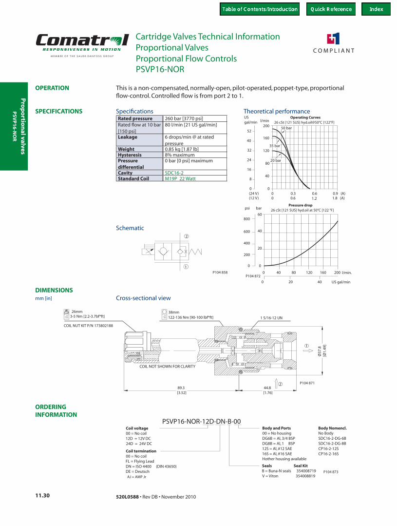
PSVP16-NOR-12D-DN-B-00Body and Ports00 = No housingDG6B = Al, 3/4 BSPDG8B = Al, 1 BSP12S = Al, #12 SAE16S = Al, #16 SAEHother housing available
Seals Seal KitB = Buna-N seals 354008719V = Viton 354008819
Coil voltage00 = No coil12D = 12V DC24D = 24V DC
P104 873AJ = AMP Jr
This is a non-compensated, normally-open, pilot-operated, poppet-type, proportional flow-control. Controlled flow is from port 2 to 1.
Rated pressure 260 bar [3770 psi]Rated flow at 10 bar [150 psi]
80 l/min [21 US gal/min]
Leakage 6 drops/min @ at rated pressure
Weight 0.85 kg [1.87 lb]Hysteresis 8% maximumPressure differential
0 bar [0 psi] maximum
Cavity SDC16-2Standard Coil M19P 22 Watt
Theoretical performance
Schematic
Cross-sectional view
SpecificationsPSV
P1
6-N
OR
PSVP16-NOR
mm [in]
Proportional Flow Controls
Pro
po
rtio
nal
val
ves
Cartridge Valves Technical InformationProportional Valves
11.31520L0588 • Rev DB • November 2010
ORDERING INFORMATION
SPECIFICATIONS
DIMENSIONS
OPERATION
P104 797
P104 798
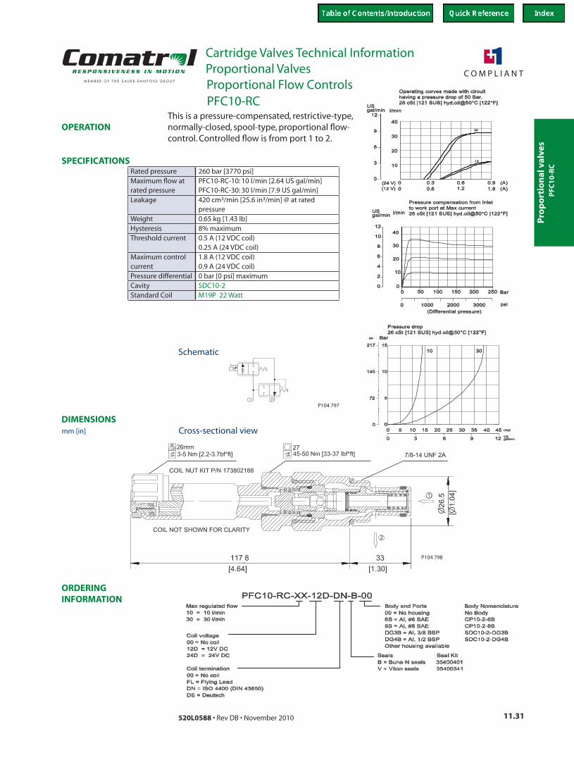
This is a pressure-compensated, restrictive-type, normally-closed, spool-type, proportional flow-control. Controlled flow is from port 1 to 2.
Rated pressure 260 bar [3770 psi]Maximum flow at rated pressure
PFC10-RC-10: 10 l/min [2.64 US gal/min]PFC10-RC-30: 30 l/min [7.9 US gal/min]
Leakage 420 cm³/min [25.6 in³/min] @ at rated pressure
Weight 0.65 kg [1.43 lb]Hysteresis 8% maximumThreshold current 0.5 A (12 VDC coil)
0.25 A (24 VDC coil)Maximum control current
1.8 A (12 VDC coil) 0.9 A (24 VDC coil)
Pressure differential 0 bar [0 psi] maximumCavity SDC10-2Standard Coil M19P 22 Watt
Schematic
Cross-sectional view
PFC10-RC
mm [in]
Proportional Flow Controls
PFC
10
-RC
Pro
po
rtion
al valves
Cartridge Valves Technical InformationProportional Valves
11.32 520L0588 • Rev DB • November 2010
ORDERING INFORMATION
SPECIFICATIONS
DIMENSIONS
OPERATION
P104 797
P104 812
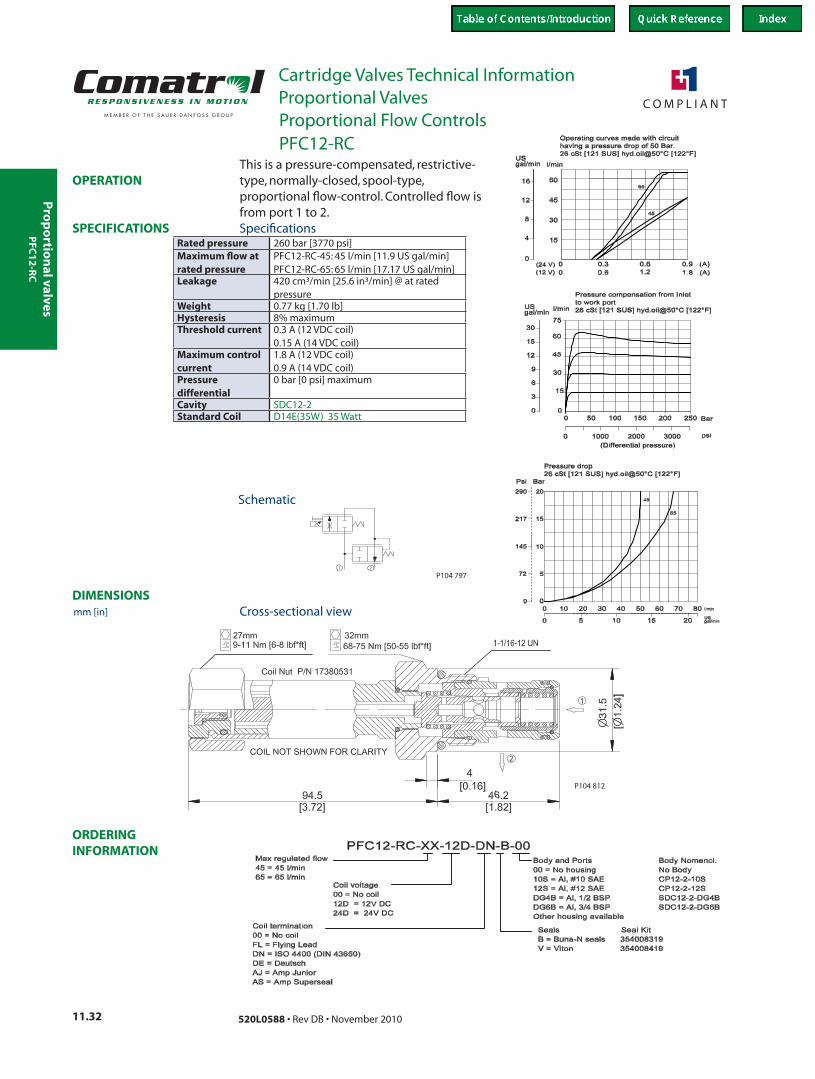
This is a pressure-compensated, restrictive-type, normally-closed, spool-type, proportional flow-control. Controlled flow is from port 1 to 2.
Rated pressure 260 bar [3770 psi]Maximum flow at rated pressure
PFC12-RC-45: 45 l/min [11.9 US gal/min]PFC12-RC-65: 65 l/min [17.17 US gal/min]
Leakage 420 cm³/min [25.6 in³/min] @ at rated pressure
Weight 0.77 kg [1.70 lb]Hysteresis 8% maximumThreshold current 0.3 A (12 VDC coil)
0.15 A (14 VDC coil)Maximum control current
1.8 A (12 VDC coil) 0.9 A (14 VDC coil)
Pressure differential
0 bar [0 psi] maximum
Cavity SDC12-2Standard Coil D14E(35W) 35 Watt
Schematic
Cross-sectional view
Specifications
PFC12-RC
mm [in]
Proportional Flow Controls
PFC
12
-RC
Pro
po
rtio
nal
val
ves
Cartridge Valves Technical InformationProportional Valves
11.33520L0588 • Rev DB • November 2010
ORDERING INFORMATION
SPECIFICATIONS
DIMENSIONS
OPERATION
00
0.3 0.6 0.9 (A)
20
40
60
80
100l/min
0 1.2 1.8 (A)(24 V)(12 V)
0
USgal/min
20
16
12
8
4
24
Operating curves made with circuithaving a pressure drop of 50 bar.
26 cSt [121 SUS] hyd.oil@50°C [122°F]
24
4
8
12
16
20
USgal/min
0
psi10000 2000 3000(Differential pressure)
00
50 100 150 200
20
40
60
80
100
l/min
250 bar
Pressure compensation from Inletto work port at max current
26 cSt [121 SUS] hyd.oil@50°C [122°F]
0.6
P104 826
P104 797
99.90[3.93]
46.40[1.83]
6.40[0.25]
37.8
0
[1.
49]
COIL NOT SHOWN FOR CLARITY
Coil Nut P/N 17380531
27mm9-11 Nm [6-8 lbf*ft] 1 5/16-12 UN122-136 Nm [90-100 lbf*ft]
38mm
2
1
P104 825
Coil termination00 = No coilFL = Flying LeadDN = ISO 4400 (DIN 43650)DE = DeutschAJ = Amp JuniorAS = Amp Superseal
PFC16-RC-90-12D-DN-B-00
Seals Seal KitB = Buna-N seals 354008719V = Viton 354008819
Coil voltage00 = No coil12D = 12V DC24D = 24V DC
Max regulated flow90 = 90 l/min
Body and Ports00 = No housingDG6B = Al, 3/4 BSPDG8B = Al, 1 BSP12S = Al, #12 SAE16S = Al, #16 SAEOther housing available
Body Nomencl.No BodySDC16-2-DG-6BSDC16-2-DG-8BCP16-2-12SCP16-2-16S
P104 827
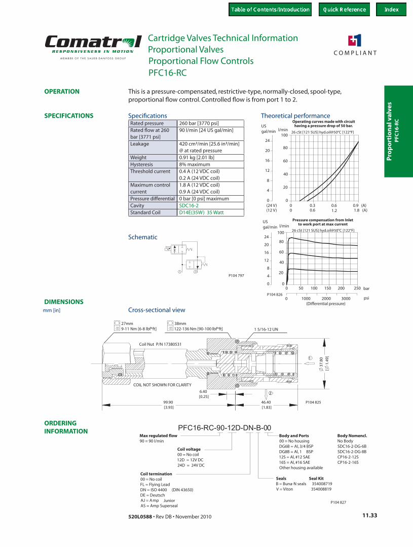
This is a pressure-compensated, restrictive-type, normally-closed, spool-type, proportional flow control. Controlled flow is from port 1 to 2.
Rated pressure 260 bar [3770 psi]Rated flow at 260 bar [3771 psi]
90 l/min [24 US gal/min]
Leakage 420 cm³/min [25.6 in³/min] @ at rated pressure
Weight 0.91 kg [2.01 lb]Hysteresis 8% maximumThreshold current 0.4 A (12 VDC coil)
0.2 A (24 VDC coil)Maximum control current
1.8 A (12 VDC coil) 0.9 A (24 VDC coil)
Pressure differential 0 bar [0 psi] maximumCavity SDC16-2Standard Coil D14E(35W) 35 Watt
Theoretical performance
Schematic
Cross-sectional view
Specifications
PFC16-RC
mm [in]
Proportional Flow Controls
PFC
16
-RC

Pro
po
rtion
al valves
Cartridge Valves Technical InformationProportional Valves
11.34 520L0588 • Rev DB • November 2010
ORDERING INFORMATION
SPECIFICATIONS
DIMENSIONS
OPERATION
P104 802
P104 803
Max regulated flow
30 = 30 l/min
Body NomenclatureNo BodyCP10-2-6SCP10-2-8SSDC10-2-DG3BSDC10-2-DG4B
Coil termination00 = No coilFL = Flying LeadDN = ISO 4400 (DIN 43650)DE = Deutsch
PFC10-RO-30-12D-DN-B-00Body and Ports00 = No housing6S = Al, #6 SAE8S = Al, #8 SAEDG3B = Al, 3/8 BSPDG4B = Al, 1/2 BSPOther housing available
Seals Seal KitB = Buna-N seals 354004019V = Viton seals 354003419
Coil voltage00 = No coil12D = 12V DC24D = 24V DC
P104 805
10 = 10 l/min
AJ = AMP Jr
This is a pressure-compensated, restrictive-type, normally-open, spool-type, proportional flow-control. Controlled flow is from port 1 to 2.
Rated pressure 260 bar [3770 psi]maximum flow at rated pressure
PFC10-RO-10: 10 l/min [2.64 US gal/min]PFC10-RO-30: 30 l/min [7.9 US gal/min]
Leakage 420 cm³/min [25.6 in³/min] @ at rated pressure
Weight 0.65 kg [1.43 lb]Hysteresis 8% maximumThreshold current 0.2 A (12 VDC coil)
0.1 A (24 VDC coil)Maximum control current
1.8 A (12 VDC coil) 0.9 A (24 VDC coil)
Pressure differential
0 bar [0 psi] maximum
Cavity SDC10-2Standard Coil M19P 22 Watt
Theoretical performance
Schematic
Cross-sectional view
Specifications
PFC10-RO
mm [in]
Proportional Flow Controls
PFC
10
-RO
Pro
po
rtio
nal
val
ves
Cartridge Valves Technical InformationProportional Valves
11.35520L0588 • Rev DB • November 2010
ORDERING INFORMATION
SPECIFICATIONS
DIMENSIONS
OPERATION
P104 802
P104 816
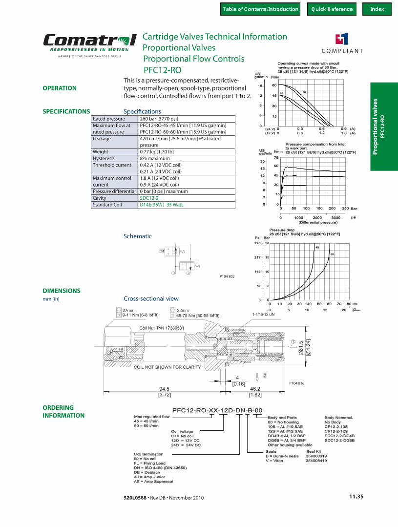
This is a pressure-compensated, restrictive-type, normally-open, spool-type, proportional flow-control. Controlled flow is from port 1 to 2.
Rated pressure 260 bar [3770 psi]Maximum flow at rated pressure
PFC12-RO-45: 45 l/min [11.9 US gal/min]PFC12-RO-60: 60 l/min [15.9 US gal/min]
Leakage 420 cm³/min [25.6 in³/min] @ at rated pressure
Weight 0.77 kg [1.70 lb]Hysteresis 8% maximumThreshold current 0.42 A (12 VDC coil)
0.21 A (24 VDC coil)Maximum control current
1.8 A (12 VDC coil) 0.9 A (24 VDC coil)
Pressure differential 0 bar [0 psi] maximumCavity SDC12-2Standard Coil D14E(35W) 35 Watt
Schematic
Cross-sectional view
Specifications
PFC12-RO
mm [in]
Proportional Flow Controls
PFC
12
-RO
Pro
po
rtion
al valves
Cartridge Valves Technical InformationProportional Valves
11.36 520L0588 • Rev DB • November 2010
ORDERING INFORMATION
SPECIFICATIONS
DIMENSIONS
OPERATION
00
0.3 0.6 0.9 (A)
20
40
60
80
100l/min
0 1.2 1.8 (A)(24 V)(12 V)
0
USgal/min
20
16
12
8
4
24
Operating curves made with circuithaving a pressure drop of 50 bar.26 cSt [121 SUS] hyd.oil@50°C [122°F]
Pressure compensation from Inletto work port at max current
26 cSt [121 SUS] hyd.oil@50°C [122°F]
bar250
l/min
100
80
60
40
20
200150100500
0
(Differential pressure)300020000 1000 psi
0
USgal/min
20
16
12
8
4
24
0.6
P104 830
P104 802
Ø37
.80
[Ø1.
49]
46.40[1.83]
6.40[0.25]
99.90[3.93]
27mm9-11 Nm [6-8 lbf*ft]
2
1
1 5/16-12 UN122-136 Nm [90-100 lbf*ft]38mm
COIL NOT SHOWN FOR CLARITY
Coil Nut P/N 17380531
P104 829
Body Nomencl.No BodySDC16-2-DG-6BSDC16-2-DG-8BCP16-2-12SCP16-2-16S
Body and Ports00 = No housingDG6B = Al, 3/4 BSPDG8B = Al, 1 BSP12S = Al, #12 SAE16S = Al, #16 SAEOther housing available
Max regulated flow85 = 85 l/min
Coil voltage00 = No coil12D = 12V DC24D = 24V DC
Seals Seal KitB = Buna-N seals 354008719V = Viton 354008819
PFC16-RO-85-12D-DN-B-00
Coil termination00 = No coilFL = Flying LeadDN = ISO 4400 (DIN 43650)DE = DeutschAJ = Amp JuniorAS = Amp Superseal
P104 831
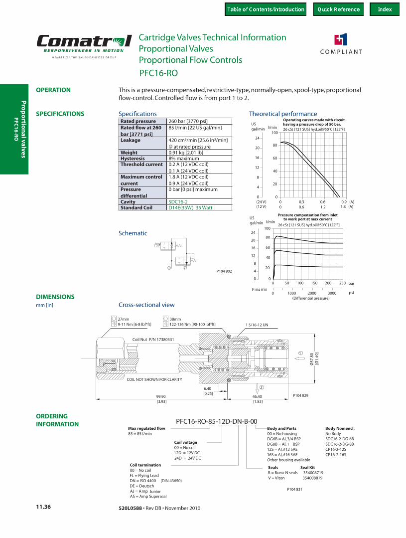
This is a pressure-compensated, restrictive-type, normally-open, spool-type, proportional flow-control. Controlled flow is from port 1 to 2.
Rated pressure 260 bar [3770 psi]Rated flow at 260 bar [3771 psi]
85 l/min [22 US gal/min]
Leakage 420 cm³/min [25.6 in³/min] @ at rated pressure
Weight 0.91 kg [2.01 lb]Hysteresis 8% maximumThreshold current 0.2 A (12 VDC coil)
0.1 A (24 VDC coil)Maximum control current
1.8 A (12 VDC coil) 0.9 A (24 VDC coil)
Pressure differential
0 bar [0 psi] maximum
Cavity SDC16-2Standard Coil D14E(35W) 35 Watt
Theoretical performance
Schematic
Cross-sectional view
Specifications
PFC16-RO
mm [in]
Proportional Flow Controls
PFC
16
-RO
Pro
po
rtio
nal
val
ves
Cartridge Valves Technical InformationProportional Valves
11.37520L0588 • Rev DB • November 2010
ORDERING INFORMATION
SPECIFICATIONS
DIMENSIONS
OPERATION
P104 789
P104 790
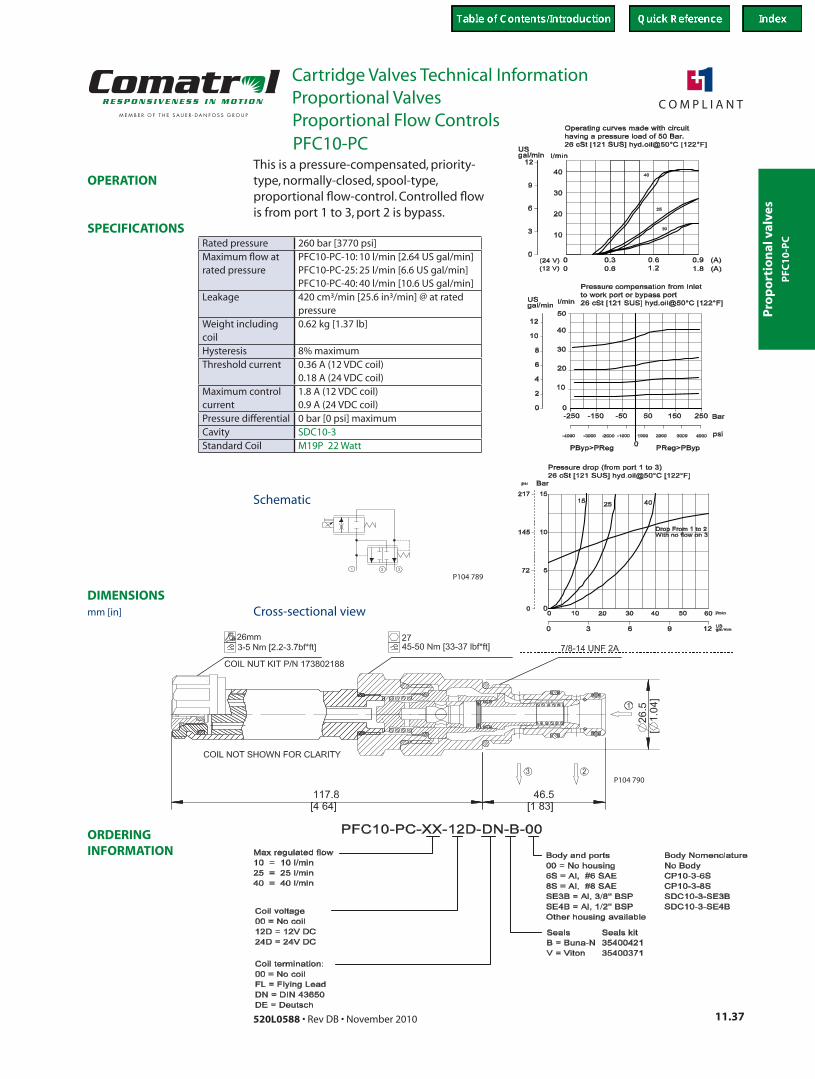
This is a pressure-compensated, priority-type, normally-closed, spool-type, proportional flow-control. Controlled flow is from port 1 to 3, port 2 is bypass.
Rated pressure 260 bar [3770 psi]Maximum flow at rated pressure
PFC10-PC-10: 10 l/min [2.64 US gal/min]PFC10-PC-25: 25 l/min [6.6 US gal/min]PFC10-PC-40: 40 l/min [10.6 US gal/min]
Leakage 420 cm³/min [25.6 in³/min] @ at rated pressure
Weight including coil
0.62 kg [1.37 lb]
Hysteresis 8% maximumThreshold current 0.36 A (12 VDC coil)
0.18 A (24 VDC coil)Maximum control current
1.8 A (12 VDC coil) 0.9 A (24 VDC coil)
Pressure differential 0 bar [0 psi] maximumCavity SDC10-3Standard Coil M19P 22 Watt
Schematic
Cross-sectional view
PFC
10
-PC
PFC10-PC
mm [in]
Proportional Flow Controls
Pro
po
rtion
al valves
Cartridge Valves Technical InformationProportional Valves
11.38 520L0588 • Rev DB • November 2010
ORDERING INFORMATION
SPECIFICATIONS
DIMENSIONS
OPERATION
P104 789
P104 806
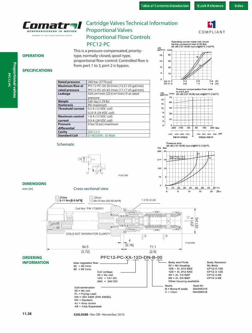
This is a pressure-compensated, priority-type, normally-closed, spool-type, proportional flow-control. Controlled flow is from port 1 to 3, port 2 is bypass.
Rated pressure 260 bar [3770 psi]Maximum flow at rated pressure
PFC12-PC-50: 50 l/min [13.21 US gal/min]PFC12-PC-65: 65 l/min [17.17 US gal/min]
Leakage 420 cm³/min [25.6 in³/min] @ at rated pressure
Weight 0.81 kg [1.79 lb]Hysteresis 8% maximumThreshold current 0.5 A (12 VDC coil)
0.25 A (24 VDC coil)Maximum control current
1.8 A (12 VDC coil) 0.9 A (24 VDC coil)
Pressure differential
0 bar [0 psi] maximum
Cavity SDC12-3Standard Coil D14E(35W) 35 Watt
Cross-sectional view
PFC
12
-PC
PFC12-PC
mm [in]
Proportional Flow Controls
Schematic
Pro
po
rtio
nal
val
ves
Cartridge Valves Technical InformationProportional Valves
11.39520L0588 • Rev DB • November 2010
ORDERING INFORMATION
SPECIFICATIONS
DIMENSIONS
OPERATION
1.2
USgal/min
Operating curves made with circuithaving a pressure drop of 50 bar.
26 cSt [121 SUS] hyd.oil@50°C [122°F]
USgal/min
Pressure compensation from Inletto work port
26 cSt [121 SUS] hyd.oil@50°C [122°F]
4000-4000 -3000 30002000
bar
psiP104 820
P104 789
6.4[0.25]
P104 819
Max regulated flow85 = 85 l/min
Coil termination00 = No coilFL = Flying LeadDN = ISO 4400 (DIN 43650)DE = DeutschAJ = Amp JuniorAS = Amp Superseal
PFC16-PC-85-12D-DN-B-00
Coil voltage00 = No coil12D = 12V DC24D = 24V DC
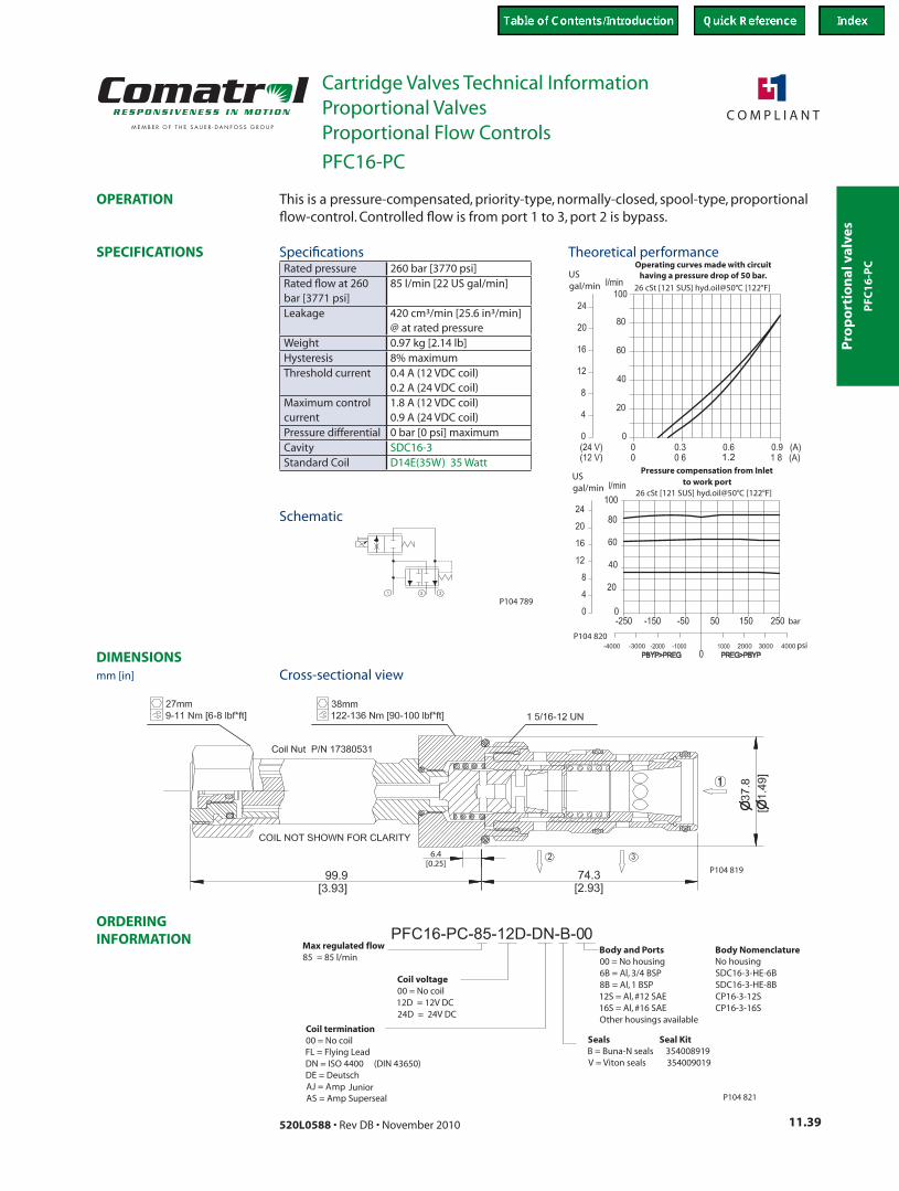
Body NomenclatureNo housingSDC16-3-HE-6BSDC16-3-HE-8BCP16-3-12SCP16-3-16S
Body and Ports00 = No housing6B = Al, 3/4 BSP8B = Al, 1 BSP12S = Al, #12 SAE16S = Al, #16 SAEOther housings available
Seals Seal KitB = Buna-N seals 354008919V = Viton seals 354009019
P104 821
This is a pressure-compensated, priority-type, normally-closed, spool-type, proportional flow-control. Controlled flow is from port 1 to 3, port 2 is bypass.
Rated pressure 260 bar [3770 psi]Rated flow at 260 bar [3771 psi]
85 l/min [22 US gal/min]
Leakage 420 cm³/min [25.6 in³/min] @ at rated pressure
Weight 0.97 kg [2.14 lb]Hysteresis 8% maximumThreshold current 0.4 A (12 VDC coil)
0.2 A (24 VDC coil)Maximum control current
1.8 A (12 VDC coil) 0.9 A (24 VDC coil)
Pressure differential 0 bar [0 psi] maximumCavity SDC16-3Standard Coil D14E(35W) 35 Watt
Theoretical performance
Schematic
Cross-sectional view
Specifications
PFC
16
-PC
PFC16-PC
mm [in]
Proportional Flow Controls
Pro
po
rtion
al valves
Cartridge Valves Technical InformationProportional Valves
11.40 520L0588 • Rev DB • November 2010
ORDERING INFORMATION
SPECIFICATIONS
DIMENSIONS
OPERATION
P104 793
P104 794
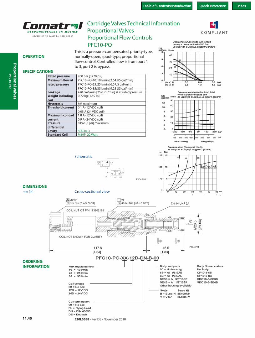
This is a pressure-compensated, priority-type, normally-open, spool-type, proportional flow-control. Controlled flow is from port 1 to 3, port 2 is bypass.
Rated pressure 260 bar [3770 psi]Maximum flow at rated pressure
PFC10-PO-10: 10 l/min [2.64 US gal/min]PFC10-PO-25: 25 l/min [6.6 US gal/min]PFC10-PO-35: 35 l/min [9.25 US gal/min]
Leakage 420 cm³/min [25.6 in³/min] @ at rated pressureWeight including coil
0.72 kg [1.59 lb]
Hysteresis 8% maximumThreshold current 0.1 A (12 VDC coil)
0.05 A (24 VDC coil)Maximum control current
1.8 A (12 VDC coil) 0.9 A (24 VDC coil)
Pressure differential
0 bar [0 psi] maximum
Cavity SDC10-3Standard Coil M19P 22 Watt
Schematic
Cross-sectional view
PFC10-PO
mm [in]
Proportional Flow Controls
PFC
10
-PO
Pro
po
rtio
nal
val
ves
Cartridge Valves Technical InformationProportional Valves
11.41520L0588 • Rev DB • November 2010
ORDERING INFORMATION
SPECIFICATIONS
DIMENSIONS
OPERATION
P104 793
P104 809
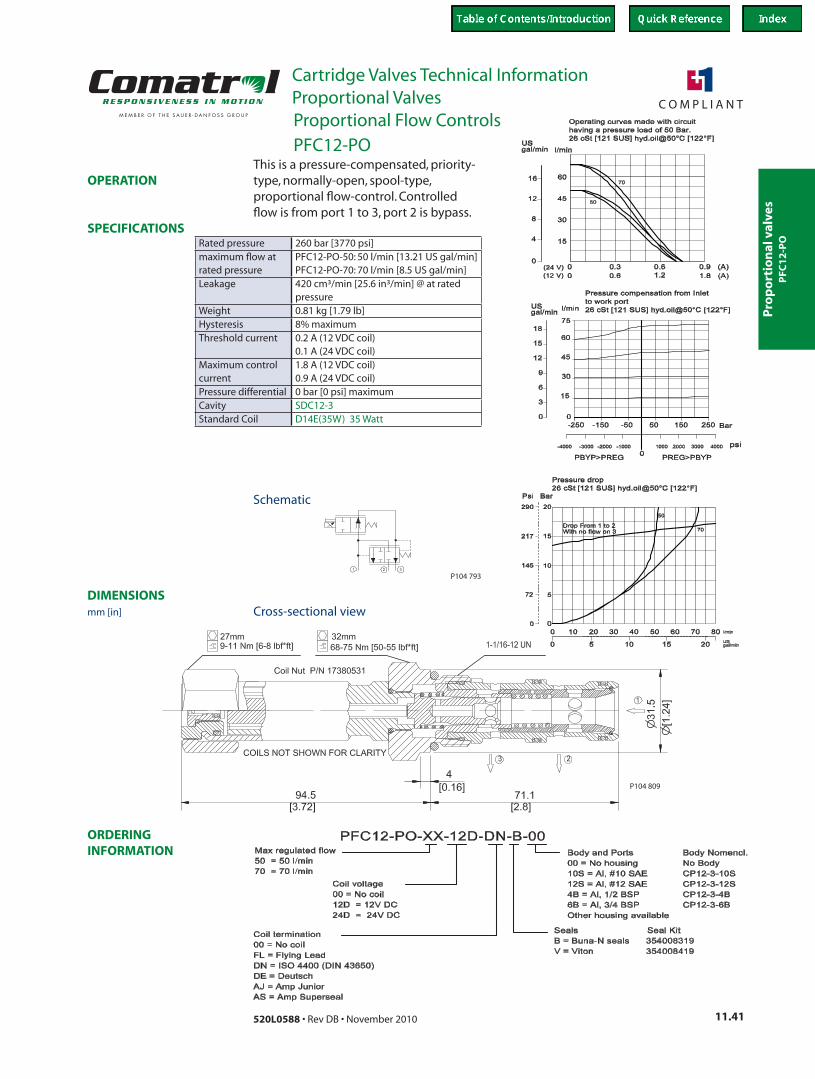
This is a pressure-compensated, priority-type, normally-open, spool-type, proportional flow-control. Controlled flow is from port 1 to 3, port 2 is bypass.
Rated pressure 260 bar [3770 psi]maximum flow at rated pressure
PFC12-PO-50: 50 l/min [13.21 US gal/min]PFC12-PO-70: 70 l/min [8.5 US gal/min]
Leakage 420 cm³/min [25.6 in³/min] @ at rated pressure
Weight 0.81 kg [1.79 lb]Hysteresis 8% maximumThreshold current 0.2 A (12 VDC coil)
0.1 A (24 VDC coil)Maximum control current
1.8 A (12 VDC coil) 0.9 A (24 VDC coil)
Pressure differential 0 bar [0 psi] maximumCavity SDC12-3Standard Coil D14E(35W) 35 Watt
Schematic
Cross-sectional view
PFC12-PO
mm [in]
Proportional Flow Controls
PFC
12
-PO
Pro
po
rtion
al valves
Cartridge Valves Technical InformationProportional Valves
11.42 520L0588 • Rev DB • November 2010
ORDERING INFORMATION
SPECIFICATIONS
DIMENSIONS
OPERATION
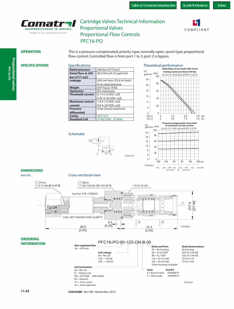
1.2
USgal/min
Operating curves made with circuithaving a pressure drop of 50 bar.
26 cSt [121 SUS] hyd.oil@50°C [122°F]
USgal/min
Pressure compensation from Inletto work port at max current
26 cSt [121 SUS] hyd.oil@50°C [122°F]
bar
psi-2000 2000
P104 823
P104 793
P104 822
Coil voltage00 = No coil12D = 12V DC24D = 24V DC
Seals Seal KitB = Buna-N seals 354008919V = Viton seals 354009019
Body and Ports00 = No housing6B = Al, 3/4 BSP8B = Al, 1 BSP12S = Al, #12 SAE16S = Al, #16 SAEOther housings available
PFC16-PO-90-12D-DN-B-00
Coil termination00 = No coilFL = Flying LeadDN = ISO 4400 (DIN 43650)DE = DeutschA J = Amp JuniorAS = Amp Superseal
Body NomenclatureNo housingSDC16-3-HE-6BSDC16-3-HE-8BCP16-3-12SCP16-3-16S
Max regulated flow90 = 90 l/min
P104 824
This is a pressure-compensated, priority-type, normally-open, spool-type, proportional flow-control. Controlled flow is from port 1 to 3, port 2 is bypass.
Rated pressure 260 bar [3770 psi]Rated flow at 260 bar [3771 psi]
90 l/min [24 US gal/min]
Leakage 420 cm³/min [25.6 in³/min] @ at rated pressure
Weight 0.97 kg [2.14 lb]Hysteresis 8% maximumThreshold current 0.1 A (12 VDC coil)
0.05 A (24 VDC coil)Maximum control current
1.8 A (12 VDC coil) 0.9 A (24 VDC coil)
Pressure differential
0 bar [0 psi] maximum
Cavity SDC16-3Standard Coil D14E(35W) 35 Watt
Theoretical performance
Schematic
Cross-sectional view
Specifications
PFC16-PO
mm [in]
Proportional Flow Controls
PFC
16
-PO
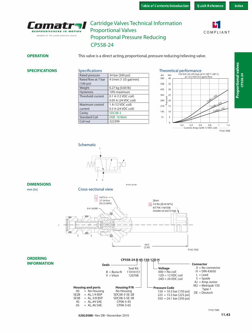
Pro
po
rtio
nal
val
ves
Cartridge Valves Technical InformationProportional Valves
11.43520L0588 • Rev DB • November 2010
ORDERING INFORMATION
SPECIFICATIONS
DIMENSIONS
OPERATION
573
psi bar
Pre
ssu
re
0.20
10
15
20
25
30
35
40
145
218
290
363
435
508
580
0.4 0.6 0.8 1 1.2
Code = 350
Code = 225
Code = 150
154 SUS (33 cSt) hyd. oil @ 100° F (38° C)at 1.0 L/min [0.3 gpm] flow
Current, Amps (with 12 VDC coil)P102 700E
P102 433E
2
1
3
64.9[2.56]
1
2 3
3/4-16UNF
ht
0.875 in27-34 N.m[20-25 lbf.ft]
P102 705E
26mm3-5 Nm [26-44 lbf*in]KIT P/N 11041556includes nut and O-rings
CP558-24-B-4S-150-12D-H
SealsSeal Kit
B = Buna-N 11016151V = Viton 120708
Connector0 = No connectorH = DIN 43650L = LeadS = Spade
AJ = Amp JuniorM2 = Metripak 150
Type 1DE = Deutsch
Pressure Code150 = 10.3 bar [150 psi]225 = 15.5 bar [225 psi]350 = 24.1 bar [350 psi]
P102 708E
Voltage000 = No coil12D = 12 VDC coil24D = 24 VDC coil
Housing and ports Housing P/N00 = No Housing No Housing
SE2B = AL,1/4 BSP SDC08-3-SE-2BSE3B = AL, 3/8 BSP SDC08-3-SE-3B
4S = AL, #4 SAE CP08-3-4S6S = AL, #6 SAE CP08-3-6S
This valve is a direct acting, proportional, pressure reducing/relieving valve.
Rated pressure 34 bar [500 psi]Rated flow at 7 bar [100 psi]
4 l/min [1 US gal/min]
Weight 0.27 kg [0.60 lb]Hysteresis 10% maximumThreshold current 0.1 A (12 VDC coil)
0.05 A (24 VDC coil)Maximum control current
1 A (12 VDC coil) 0.5 A (24 VDC coil)
Cavity SDC08-3Standard Coil D08 16 WattCoil nut 322399
Theoretical performance
Schematic
Cross-sectional view
Specifications
CP558-24
mm [in]
Proportional Pressure Reducing
CP
55
8-2
4
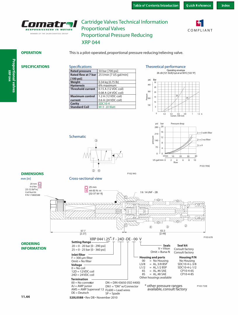
Pro
po
rtion
al valves
Cartridge Valves Technical InformationProportional Valves
11.44 520L0588 • Rev DB • November 2010
ORDERING INFORMATION
SPECIFICATIONS
DIMENSIONS
OPERATION
US gal/min
l/min
10
16
8
12
20280
210
140
0
70
psi bar
4
0
86420
40302010
Pressure drop
pre
ssu
re
flow
2 3 with filter
2 3 no filter
3 4
P103 705E
Operating envelope26 cSt [121 SUS] hyd.oil at 50ウC [122 ウF]
5
10
15
20
Bar
0 0.2 0.4 0.6 0.8
25
30
1.21 A
psi
100
200
300
400
2520
Current, (12D Coil)
Pres
sure
42
3
P102 943
63.3[2.49]
57.7[2.27]
4 3 2
P103 678
20 mm4-6 Nm
[35-53 lbf*in]Coil Nut KitP/N 173800588
ht 25 mm
44-50 N m[32-37 lbf ft] 14UNF - 2B7/8
XRP 044 \ 25 - F - 24D -DE - 00 - V
P103 733E
F = filterOmit = No filter
300 µm
Seals
Inlet filter
V = VitonOmit = Buna-N
Voltage0 = No coil12D = 12VDC coil24D = 24VDC coil
Termination00 = No connectorAJ = AMP juniorAMS = AMP Superseal 1.5DE = Deutsch
DN = DIN 43650 (ISO 4400)DN1 = “DN” w/ConnectorFL600 = Lead wiresSP = Spade
Housing and ports Housing P/N00 = No Housing No Housing
L3/8 = AL, 3/8 BSP SDC10-4-L-3/8L1/2 = AL,1/2 BSP SDC10-4-L-1/2
6S = AL, #6 SAE CP10-4-6S8S = AL, #8 SAE CP10-4-8S
Other housings available
* other pressure ranges available, consult factory
*
Seal kitConsult factoryConsult factory
Setting Range20 = 0 - 20 bar [0 - 290 psi]25 = 0 - 25 bar [0 - 360 psi]
This is a pilot-operated, proportional pressure reducing/relieving valve.
Rated pressure 50 bar [700 psi]Rated flow at 7 bar [100 psi]
25 l/min [7 US gal/min]
Weight 0.34 kg [0.75 lb]Hysteresis 6% maximumThreshold current 0.15 A (12 VDC coil)
0.08 A (24 VDC coil)Maximum control current
1.2 A (12 VDC coil) 0.6 A (24 VDC coil)
Cavity SDC10-4Standard Coil M13 20 Watt
Theoretical performance
Schematic
Cross-sectional view
Specifications
XRP 044
mm [in]
Proportional Pressure Reducing
XR
P 0
44
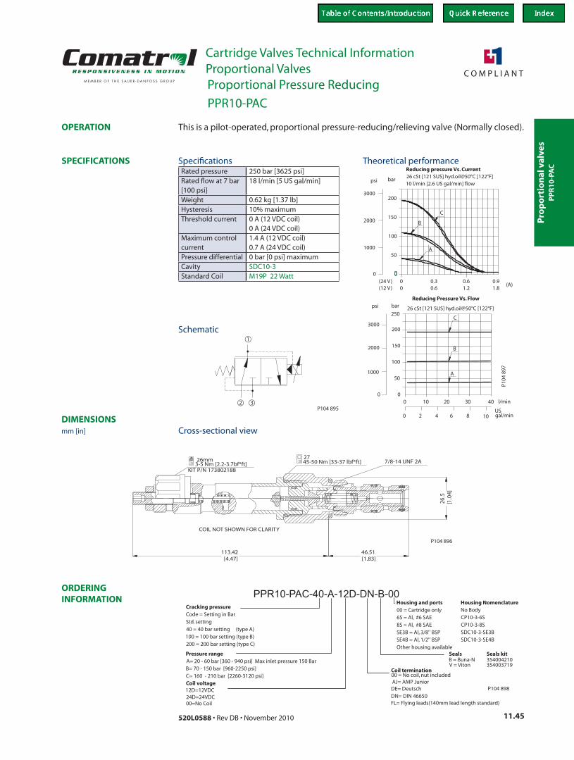
Pro
po
rtio
nal
val
ves
Cartridge Valves Technical InformationProportional Valves
11.45520L0588 • Rev DB • November 2010
ORDERING INFORMATION
SPECIFICATIONS
DIMENSIONS
OPERATION
Reducing pressure Vs. Current26 cSt [121 SUS] hyd.oil@50°C [122°F]10 l/min [2.6 US gal/min] flow
0
A
B
C
(A)
psi
3000
2000
1000
0.9
50
100
150
200
bar
1.8(24 V)(12 V) 1.2
0.60.60.3
00
A
B
C
psi bar
3000
2000
100050
100
150
200
250
USgal/min2 6 840 10
00
10 20 30 40 l/min
Reducing Pressure Vs. Flow
26 cSt [121 SUS] hyd.oil@50°C [122°F]
0
P104
897
1
2 3P104 895
113.42[4.47]
26.5
[1.0
4]
46.51[1.83]
7/8-14 UNF 2A45-50 Nm [33-37 lbf*ft]27
KIT P/N 1738021883-5 Nm [2.2-3.7bf*ft]26mm
COIL NOT SHOWN FOR CLARITY
P104 896
Seals kit354004210354003719
PPR10-PAC-40-A-12D-DN-B-00
SealsB = Buna-NV = Viton
Coil voltage12D=12VDC24D=24VDC00=No Coil
Coil termination00 = No coil, nut includedAJ= AMP JuniorDE= DeutschDN= DIN 46650FL= Flying leads(140mm lead length standard)
Cracking pressureCode = Setting in BarStd. setting40 = 40 bar setting (type A)100 = 100 bar setting (type B)200 = 200 bar setting (type C)
Pressure rangeA= 20 - 60 bar [360 - 940 psi] Max inlet pressure 150 BarB= 70 - 150 bar [960-2250 psi]C= 160 - 210 bar [2260-3120 psi]
Housing and ports00 = Cartridge only6S = Al, #6 SAE8S = Al, #8 SAESE3B = Al, 3/8'' BSPSE4B = Al, 1/2'' BSPOther housing available
Housing NomenclatureNo BodyCP10-3-6SCP10-3-8SSDC10-3-SE3BSDC10-3-SE4B
P104 898
This is a pilot-operated, proportional pressure-reducing/relieving valve (Normally closed).
Rated pressure 250 bar [3625 psi]Rated flow at 7 bar [100 psi]
18 l/min [5 US gal/min]
Weight 0.62 kg [1.37 lb]Hysteresis 10% maximumThreshold current 0 A (12 VDC coil)
0 A (24 VDC coil)Maximum control current
1.4 A (12 VDC coil) 0.7 A (24 VDC coil)
Pressure differential 0 bar [0 psi] maximumCavity SDC10-3Standard Coil M19P 22 Watt
Theoretical performance
Schematic
Cross-sectional view
Specifications
PPR10-PAC
mm [in]
Proportional Pressure Reducing
PP
R1
0-P
AC

Pro
po
rtion
al valves
Cartridge Valves Technical InformationProportional Valves
11.46 520L0588 • Rev DB • November 2010
ORDERING INFORMATION
SPECIFICATIONS
DIMENSIONS
OPERATION
P103 617E
0.0 0.2 2.0
0
435
870
1305
1740
2175
2610
3045
30
0
60
90
120
150
180
210
Current, Amps (with 12 VDC coil)
bar psi
210
150
70
25
0
1
2
3
4
5
6
0 2 4 6 8 10 12 14 16 18
4.84.23.73.22.62.11.61.00.50
87
73
58
44
29
15
0
L/min
US gal/min
barpsi
at 5 L/min [1.3 US gal/min] Flow Rate
Pressure vs. Current
26 cSt [123 SUS] hyd.oil @ 50 C [122° F]
Pressure Drop vs. Flow
2 to 1
0.4 0.6 0.8 1.21.0 1.4 1.81.6
26 cSt [123 SUS] hyd.oil @ 50 C [122° F]
50
P108 348E
104.4[4.11]
27 mm44-50 N m[32-37 lbf ft]
47.6[1.87]
3 2
1
M 22 x 1.5
P103 612
26mm3-5 Nm [26-44 lbf*in]KIT P/N 173802188
XRP 06 - 70 - 12D -DE - EN - 00 - V
25 = 6-25 bar50
[90-360 psi]= 6-55 bar [90-800 psi]
70 = 5-75 bar [90-1100 psi]150 = 8-155 bar [120-2200 psi]210 = 9-210 bar [130-3100 psi]
P103 732E0 = P0 ush control (Standard)EN = Screw control
SealsSetting range
Manual override
V = VitonOmit = Buna-N
Voltage00 = No coil12D = 12VDC24D = 24VDC
Termination
Housing and ports Housing P/N00 = No Housing No Housing
SE6S = AL, #6 SAE NCS06/3-SE-6SSE8S = AL, #8 SAE NCS06/3-SE-8SSE3/8 = AL, 3/8 BSP NCS06/3-SE-3/8SE1/2 = AL, 1/2 BSP NCS06/3-SE-1/2
00 = No connector DNAJ = AMP Jr
= DIN 43650 (ISO 4400)
FL600 = Lead wiresDE = Deutsch
Seals230000110230000070
DN1 = “DN” w/Connector
This is a pilot-operated, proportional pressure reducing/relieving valve.
Rated pressure 315 bar [4500 psi]Rated flow at 7 bar [100 psi]
25 l/min [7 US gal/min]
Weight 0.55 kg [1.21 lb]Hysteresis 3% maximumThreshold current 0 A (12 VDC coil)
0 A (24 VDC coil)Maximum control current
1.8 A (12 VDC coil) 0.9 A (24 VDC coil)
Cavity NCS06/3Standard Coil M19P 22 Watt
Theoretical performance
Schematic
Cross-sectional view
Specifications
XRP 06
mm [in]
Proportional Pressure Reducing
XR
P 0
6
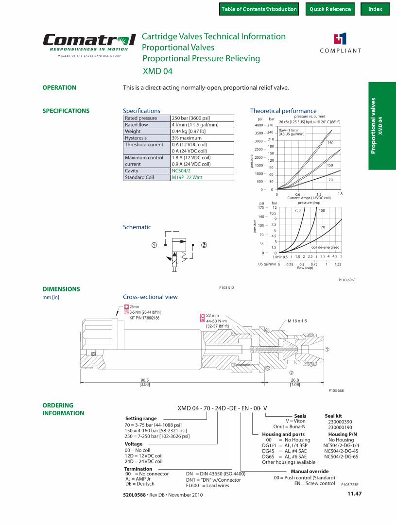
Pro
po
rtio
nal
val
ves
Cartridge Valves Technical InformationProportional Valves
11.47520L0588 • Rev DB • November 2010
ORDERING INFORMATION
SPECIFICATIONS
DIMENSIONS
OPERATION
1.5
0L/min
0
0 0.6 1.2 1.800
500 30
60
90
120
pre
ssu
re
150
180
210
240
barpsi
270
3
4.5
6
7.5
9
psi bar
10.5
12
00.5 1 1.5 2 2.5 3 3.5 4
flow=1 l/min
175
35
70
105
140
10.5 0.750.25
1000
1500
2000
2500
3000
3500
4000
1.25
4.5 5
US gal/min
pressure vs. current
26 cSt [125 SUS] hyd.oil @ 20° C [68° F]
250
150
70
250 150
70
pre
ssu
re
Current, Amps (12VDC coil)
flow (cap)
P103 696E
pressure drop
coil de-energised
(0.3 US gal/min)
P103 512
[3.56]90.5
[1.06]26.8
2
1
M 18 x 1.522 mm44-50 N m[32-37 lbf ft]
P103 668
26mm3-5 Nm [26-44 lbf*in]KIT P/N 173802188
XMD 04 - 70 - 24D -DE - EN - 00 - V
70 = 3-75 bar [44-1088 psi]150 = 4-160 bar [58-2321 psi]250 = 7-250 bar [102-3626 psi]
P103 723E
Housing and ports Housing P/N00 = No Housing No Housing
DG1/4 = AL,1/4 BSP NCS04/2-DG-1/4DG4S = AL, #4 SAE NCS04/2-DG-4SDG6S = AL, #6 SAE NCS04/2-DG-6SOther housings available
0 = P0 ush control (Standard)EN = Screw control
SealsSetting range
Manual override
V = VitonOmit = Buna-N
Voltage00 = No coil12D = 12VDC coil24D = 24VDC coil
Termination
Seal kit230000390230000190
00 = No connector DNAJ = AMP Jr
= DIN 43650 (ISO 4400)
FL600 = Lead wiresDE = DeutschDN1 = “DN” w/Connector
This is a direct-acting normally-open, proportional relief valve.
Rated pressure 250 bar [3600 psi]Rated flow 4 l/min [1 US gal/min]Weight 0.44 kg [0.97 lb]Hysteresis 3% maximumThreshold current 0 A (12 VDC coil)
0 A (24 VDC coil)Maximum control current
1.8 A (12 VDC coil) 0.9 A (24 VDC coil)
Cavity NCS04/2Standard Coil M19P 22 Watt
Theoretical performance
Schematic
Cross-sectional view
Specifications
XMD 04
mm [in]
Proportional Pressure Relieving
XM
D 0
4
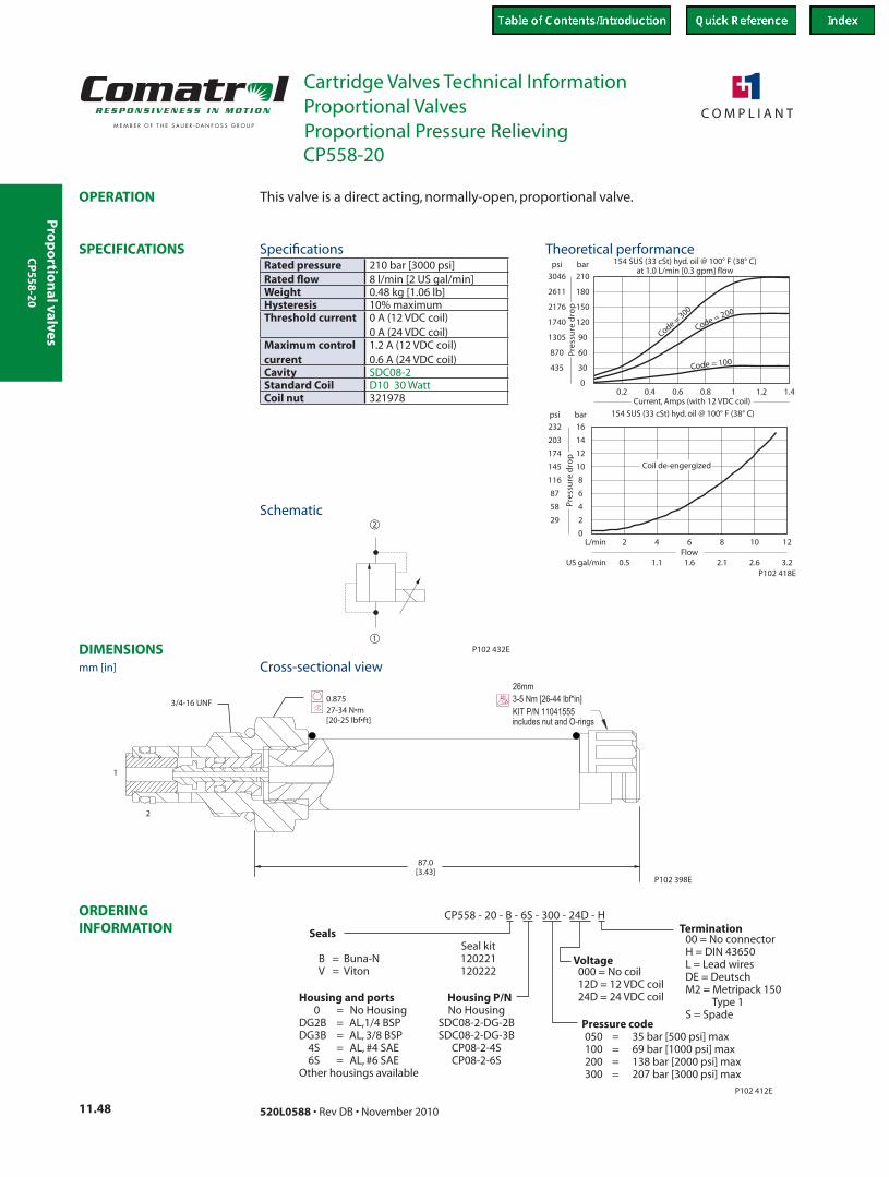
Pro
po
rtion
al valves
Cartridge Valves Technical InformationProportional Valves
11.48 520L0588 • Rev DB • November 2010
ORDERING INFORMATION
SPECIFICATIONS
DIMENSIONS
OPERATION
30435
psi bar
Pre
ssu
re d
rop
0.20
154 SUS (33 cSt) hyd. oil @ 100° F (38° C)at 1.0 L/min [0.3 gpm] flow
60
90
120
150
180
210
870
1305
1740
2176
2611
3046
0.4 0.6 0.8 1 1.2 1.4
154 SUS (33 cSt) hyd. oil @ 100° F (38° C)
229
psi bar
Pre
ssu
re d
rop
2Flow
0.5
L/min
US gal/min
0
4
6
8
10
12
14
16
58
87
116
145
174
203
232
4 6 8 10 12
1.1 1.6 2.1 2.6 3.2
Cd
=0
oe
30
Code = 200
Code = 100
Coil de-engergized
Current, Amps (with 12 VDC coil)
P102 418E
1
2
P102 432E
87.0[3.43]
ht
0.87527-34 N•m[20-25 lbf•ft]
3/4-16 UNF
1
2
P102 398E
26mm3-5 Nm [26-44 lbf*in]KIT P/N 11041555includes nut and O-rings
CP558 - 20 - B - 6S - 300 - 24D - H
SealsSeal kit
B = Buna-N 120221V = Viton 120222
Pressure code050 = 35 bar [500 psi] max100 = 69 bar [1000 psi] max200 = 138 bar [2000 psi] max300 = 207 bar [3000 psi] max
P102 412E
Housing and ports Housing P/N0 = No Housing No Housing
DG2B = AL,1/4 BSP SDC08-2-DG-2BDG3B = AL, 3/8 BSP SDC08-2-DG-3B
4S = AL, #4 SAE CP08-2-4S6S = AL, #6 SAE CP08-2-6S
Other housings available
Voltage000 = No coil12D = 12 VDC coil24D = 24 VDC coil
Termination00 = No connectorHL = Lead wiresDE = DeutschM2 = Metripack 150
Type 1S = Spade
= DIN 43650
This valve is a direct acting, normally-open, proportional valve.
Rated pressure 210 bar [3000 psi]Rated flow 8 l/min [2 US gal/min]Weight 0.48 kg [1.06 lb]Hysteresis 10% maximumThreshold current 0 A (12 VDC coil)
0 A (24 VDC coil)Maximum control current
1.2 A (12 VDC coil) 0.6 A (24 VDC coil)
Cavity SDC08-2Standard Coil D10 30 WattCoil nut 321978
Theoretical performance
Schematic
Cross-sectional view
Specifications
CP558-20
mm [in]
Proportional Pressure Relieving
CP
55
8-2
0
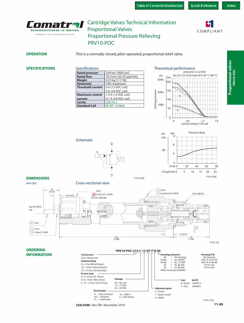
Pro
po
rtio
nal
val
ves
Cartridge Valves Technical InformationProportional Valves
11.49520L0588 • Rev DB • November 2010
ORDERING INFORMATION
SPECIFICATIONS
DIMENSIONS
OPERATION
US gal/min
l/min 806040200
0
250 10 20155
12
8
480
160
barpsi
psi
3000
2000
1000
1.80
50
100
150
200
bar
1.20.60
Sett
ing
pre
ssu
re
Pressure drop
26 cSt [125 SUS] hyd.oil @ 20° C [68° F]pressure vs. current
P104 534E
current (amps) 12V coil
C
B
A
1
2
P102 942E
P103 756
EN
PRV10-POC-215-C-12-DT-F-B-00
Seals Seal KitB = Buna-N 354000719V = Viton 354000819
Adjustment option:E = ExternalF = Tamper resistantH = Hidden
Crack pressureCode = Setting in barStandard settings55 = 55 bar [800 psi] Range A135 = 135 bar 1960 B[ psi] Range215 = 215 bar 3120 C[ psi] RangePressure rangeA= 25 - 65 bar [360 - 940 psi]B= 65 - 155 bar [940-2250 psi]C= 155 - 215 bar [2250-3120 psi]
P103 776E
Housing and ports Housing P/N00 = No Housing No Housing
DG3B = AL,3/8 BSP SDC10-2-DG-3BDG4B = AL, 1/2 BSP SDC10-2-DG-4B
6S = AL, #6 SAE CP10-2-6S8S = AL, #8 SAE CP10-2-8S
Other housings available
Voltage
00 = No coil12 = 12 VDC24 = 24 VDC
Termination
0 = No connectorDEFL = Lead wires
= Deutsch AAJ = AMP Jr
= DIN 43650
This is a normally-closed, pilot-operated, proportional relief valve.
Rated pressure 250 bar [3600 psi]Rated flow 76 l/min [20 US gal/min]Weight 0.53 kg [1.17 lb]Hysteresis 10% maximumThreshold current 0 A (12 VDC coil)
0 A (24 VDC coil)Maximum control current
1.4 A (12 VDC coil) 0.7 A (24 VDC coil)
Cavity SDC10-2Standard Coil M19P 22 Watt
Theoretical performance
Schematic
Cross-sectional view
Specifications
PRV10-POC
mm [in]
Proportional Pressure Relieving
PR
V1
0-P
OC
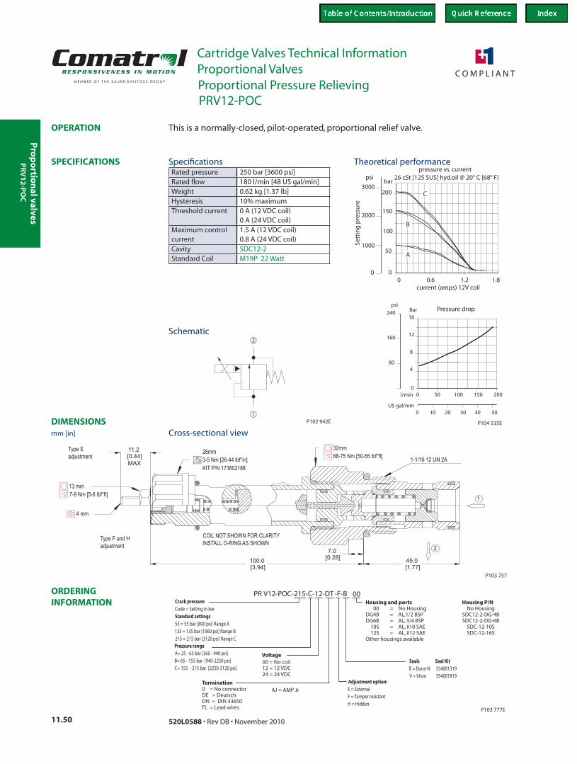
Pro
po
rtion
al valves
Cartridge Valves Technical InformationProportional Valves
11.50 520L0588 • Rev DB • November 2010
ORDERING INFORMATION
SPECIFICATIONS
DIMENSIONS
OPERATION
psi
160
804
8
12
10 30 40200 50
00
50 100 150 200l/min
0 0.6 1.2
bar
200
150
100
50
01.8
2000
3000
psi
16240 Bar
US gal/min
0
Sett
ing
pre
ssu
re
Pressure drop
26 cSt [125 SUS] hyd.oil @ 20° C [68° F]pressure vs. current
P104 535E
current (amps) 12V coil
C
B
A
1000
1
2
P102 942E
13 mm
7.0
[0.28]
11.2
[0.44]
100.0
[3.94]
45.0
[1.77]
MAX
COIL NOT SHOWN FOR CLARITY
INSTALL O-RING AS SHOWN
4 mm
7-9 Nm [5-6 lbf*ft]
68-75 Nm [50-55 lbf*ft]
32mm26mm
3-5 Nm [26-44 lbf*in]
KIT P/N 173802188
1-1/16-12 UN 2A
2
1
Type F and H
adjustment
Type E
adjustment
P103 757
PR V12-POC-215-C-12-DT -F-B 00
P103 777E
Adjustment option:E = ExternalF = Tamper resistantH = Hidden
Crack pressureCode = Setting in barStandard settings55 = 55 bar [800 psi] Range A135 = 135 bar 1960 B[ psi] Range215 = 215 bar 3120 C[ psi] RangePressure rangeA= 25 - 65 bar [360 - 940 psi]B= 65 - 155 bar [940-2250 psi]C= 155 - 215 bar [2250-3120 psi]
Housing and ports Housing P/N00 = No Housing No Housing
DG4B = AL,1/2 BSP SDC12-2-DG-4BDG6B = AL, 3/4 BSP SDC12-2-DG-6B
10S = AL, #10 SAE SDC-12-10S12S = AL, #12 SAE SDC-12-16S
Other housings available
Voltage00 = No coil12 = 12 VDC24 = 24 VDC
Termination
Seals Seal KitB = Buna-N 354001319V = Viton 354001819
0 = No connectorDE
FL = Lead wires
= DeutschDN = DIN 43650
AJ = AMP Jr
This is a normally-closed, pilot-operated, proportional relief valve.
Rated pressure 250 bar [3600 psi]Rated flow 180 l/min [48 US gal/min]Weight 0.62 kg [1.37 lb]Hysteresis 10% maximumThreshold current 0 A (12 VDC coil)
0 A (24 VDC coil)Maximum control current
1.5 A (12 VDC coil) 0.8 A (24 VDC coil)
Cavity SDC12-2Standard Coil M19P 22 Watt
Theoretical performance
Schematic
Cross-sectional view
Specifications
PRV12-POC
mm [in]
Proportional Pressure Relieving
PR
V1
2-P
OC
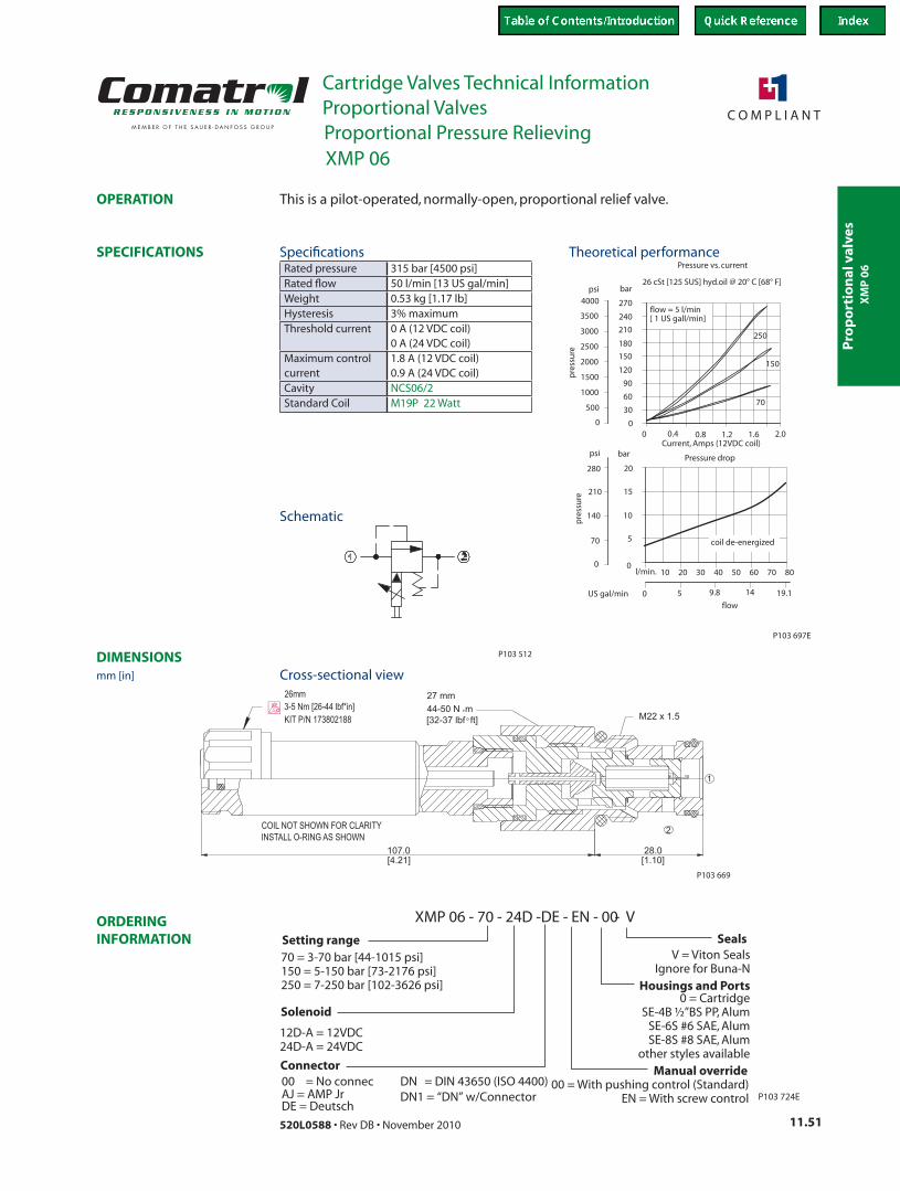
Pro
po
rtio
nal
val
ves
Cartridge Valves Technical InformationProportional Valves
11.51520L0588 • Rev DB • November 2010
ORDERING INFORMATION
SPECIFICATIONS
DIMENSIONS
OPERATION
0
20
15
10
570
020 40l/min. 60 8010 30 50 70
140
210
280
psi bar
000
500 30
60
90
120
pre
ssu
re
150
180
210
240
barpsi
270
1000
1500
2000
2500
3000
3500
4000
0.4 0.8 1.2 1.6 2.0
flow = 5 l/min
Pressure vs. current
26 cSt [125 SUS] hyd.oil @ 20° C [68° F]
250
150
70
Current, Amps (12VDC coil)
pre
ssu
re
9.8 19.11450US gal/minflow
P103 697E
Pressure drop
coil de-energized
[ 1 US gall/min]
P103 512
27 mm44-50 N m[32-37 lbf ft]
[4.21]107.0
2
[1.10]28.0
1
M22 x 1.5
P103 669
COIL NOT SHOWN FOR CLARITYINSTALL O-RING AS SHOWN
26mm3-5 Nm [26-44 lbf*in]KIT P/N 173802188
XMP 06 - 70 - 24D -DE - EN - 00 - VSeals
V = Viton SealsIgnore for Buna-N
Housings and Ports
Setting range70 = 3-70 bar [44-1015 psi]150 = 5-150 bar [73-2176 psi]250 = 7-250 bar [102-3626 psi]
Manual override0 =0 With pushing control (Standard)
EN = With screw control
Solenoid
12D-A = 12VDC 24D-A = 24VDC
0 = CartridgeSE-4B ½”BS PP, Alum
SE-6S #6 SAE, AlumSE-8S #8 SAE, Alum
other styles available
P103 724E
Connector00 = No connec DNAJ = AMP Jr
= DIN 43650 (ISO 4400)
DE = DeutschDN1 = “DN” w/Connector
This is a pilot-operated, normally-open, proportional relief valve.
Rated pressure 315 bar [4500 psi]Rated flow 50 l/min [13 US gal/min]Weight 0.53 kg [1.17 lb]Hysteresis 3% maximumThreshold current 0 A (12 VDC coil)
0 A (24 VDC coil)Maximum control current
1.8 A (12 VDC coil) 0.9 A (24 VDC coil)
Cavity NCS06/2Standard Coil M19P 22 Watt
Theoretical performance
Schematic
Cross-sectional view
Specifications
XMP 06
mm [in]
Proportional Pressure Relieving
XM
P 0
6

Pro
po
rtion
al valves
Cartridge Valves Technical InformationProportional Valves
11.52 520L0588 • Rev DB • November 2010
Notes


![Cartridge Valves Technical Information Proportional Valves Quick … · 2020. 5. 19. · PSV12-NO SDC12-2 100 l/min [26 US gal/min] 260 bar [3770 psi] 11.27 Proportional Flow Controls](https://static.fdocuments.net/doc/165x107/612d59851ecc51586942224f/cartridge-valves-technical-information-proportional-valves-quick-2020-5-19.jpg)


