Carter Pressure Fueling Nozzle - Eatonpub/@eaton/@aero/documents/... · 2 EATON Aerospace Group...
6
Carter ® Pressure Fueling Nozzle Model 64200
-
Upload
hoanghuong -
Category
Documents
-
view
227 -
download
2
Transcript of Carter Pressure Fueling Nozzle - Eatonpub/@eaton/@aero/documents/... · 2 EATON Aerospace Group...
Carter®
Pressure Fueling Nozzle Model 64200
2 EATON Aerospace Group TF100-100C May 2013
Eaton’s Carter product line of ground fueling equipment includes several underwing refueling nozzle models. Building on the success of ear-lier Carter Model 64348, the lightweight and rugged Model 64200 Pressure Refueling Nozzle is designed to increase durability and decrease mainte-nance costs.Model 64200 uses the same accessories as the earlier Model 64348 nozzle. All of these accessories now have stainless steel wear rings in swivel ball joints.
The interlock mechanism is internal to the nozzle body, therefore there are no pins to wear aircraft adapter slots. It has no collar or other moving parts on the exterior of the nozzle (with the exception of the operating lever), thereby reducing the need to replace worn components. The handles are made of a very rugged standard composite material and do not include any metal, thereby eliminating potential bending of the handles.
Options include a “U” bracket for nozzle stowage and a one-piece stirrup handle with stowage capability — no need to use the aircraft adapter or a special type of stowage device.
The operating lever, replaceable from the exterior of the nozzle and made of less expensive, more ductile material, is backed up with a boss on the nozzle body to prevent bending. The operating lever has a replaceable knob to eliminate razor-sharp abrasion wear patterns prevalent on competitor’s nozzles. The lever has also been designed to turn in a counter-clockwise direction (the earlier Model 64348 was clockwise). This eliminates interference with some aircraft that are not designed to standards.
Features
y Connects to 3-lug international standard aircraft adapter
y Self-adjusting pressure- loaded nose seal. No mechanical adjustments or springs used.
y Sampling fitting installation is standard
y Leak-free under extreme side loads, worn adapters and extreme temperatures
y Low pressure drop
y Two threaded ports in nozzle body for simultane-ous vacuum breaker and product sampling
y 2, 2½ and 3-inch NPT and BSPP threaded quick disconnect (QD) inlets available
y Optional 40, 60 & 100-mesh screens retained with snap ring for ease of removal
y 35 psi (2.413 bar), 45 psi (3.103 bar) and 55 psi (3.792) Hose End Control Valves (HECV) available. See catalog sheet TF100-76 for detailed information.
y Double redundant safety lock on/easy off QD
y Easier swiveling under all conditions. Swivel independent of QD.
y Choice of ball valve or dry break disconnect for easy strainer inspection available
Design Concepts
Model 64200BR6H
Includes 60-mesh screen, holder bracket, male adapter and standard quick disconnect
Model 64200B2F46H
Includes 60-mesh screen, 45 psi (3.103 bar) HECV with swivel end, male adapter and standard quick disconnect with 2½-inch NPT thread inlet
EATON Aerospace Group TF100-100C May 2013 3
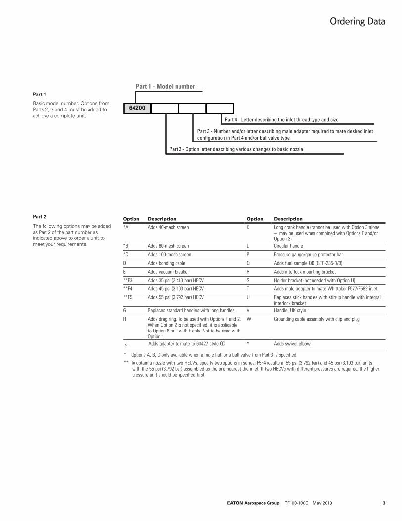
64200
Part 1 - Model number
Part 2 - Option letter describing various changes to basic nozzle
Part 3 - Number and/or letter describing male adapter required to mate desired inlet configuration in Part 4 and/or ball valve type
Part 4 - Letter describing the inlet thread type and size
Part 1
Basic model number. Options from Parts 2, 3 and 4 must be added to achieve a complete unit.
Option Description Option Description
*A Adds 40-mesh screen K Long crank handle (cannot be used with Option 3 alone – may be used when combined with Options F and/or Option 3).
*B Adds 60-mesh screen L Circular handle
*C Adds 100-mesh screen P Pressure gauge/gauge protector bar
D Adds bonding cable Q Adds fuel sample QD (GTP-235-3/8)
E Adds vacuum breaker R Adds interlock mounting bracket
**F3 Adds 35 psi (2.413 bar) HECV S Holder bracket (not needed with Option U)
**F4 Adds 45 psi (3.103 bar) HECV T Adds male adapter to mate Whittaker F577/F582 inlet
**F5 Adds 55 psi (3.792 bar) HECV U Replaces stick handles with stirrup handle with integral interlock bracket
G Replaces standard handles with long handles V Handle, UK style
H Adds drag ring. To be used with Options F and 2. When Option 2 is not specified, it is applicable to Option 6 or T with F only. Not to be used with Option 1.
W Grounding cable assembly with clip and plug
J Adds adapter to mate to 60427 style QD Y Adds swivel elbow
* Options A, B, C only available when a male half or a ball valve from Part 3 is specified** To obtain a nozzle with two HECVs, specify two options in series. F5F4 results in 55 psi (3.792 bar) and 45 psi (3.103 bar) units
with the 55 psi (3.792 bar) assembled as the one nearest the inlet. If two HECVs with different pressures are required, the higher pressure unit should be specified first.
Part 2
The following options may be added as Part 2 of the part number as indicated above to order a unit to meet your requirements.
Ordering Data
4 EATON Aerospace Group TF100-100C May 2013
Ordering Data
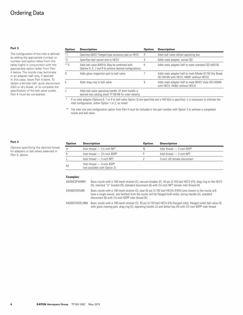
Option Description Option Description
*1 Specifies 60427 flanged-type accessory pad on HECV R Adds ball valve defuel operating key
*2 Specifies ball swivel end to HECV 4 Adds male adapter, swivel QD
**3 Adds ball valve (64015). May be combined with Options D, E, J and R to achieve desired configurations.
6 Adds male adapter half to mate standard QD (44316)
D Adds glass inspection port to ball valve 7 Adds male adapter half to mate Model 61154 Dry Break QD (44185 with HECV; 44697 without HECV)
E Adds drag ring to ball valve 9 Adds male adapter half to mate 60427 style QD (43046 with HECV; 44362 without HECV)
J Adds ball valve operating handle. (If short handle is desired see catalog sheet TF100-88 for order details).
* If no inlet adapter (Options 6, 7 or 9 or ball valve Option 3) are specified and a HECV(s) is specified, it is necessary to indicate the inlet configuration, either Option 1 or 2, as noted
** The inlet size and configuration option from Part 4 must be included in the part number with Option 3 to achieve a completed nozzle and ball valve
Part 3
The configuration of the inlet is defined by adding the appropriate number or number and option letter from the table (right) in conjunction with the appropriate option letter from Part 4 below. The nozzle may terminate in an adapter half only, if desired. In this case, leave Part 4 blank. To obtain a female half, quick disconnect (QD) or dry break, or to complete the specification of the ball valve outlet, Part 4 must be completed.
Option Description Option Description
H Inlet thread — 2½-inch NPT N Inlet thread — 2-inch BSPP
K Inlet thread — 2½-inch BSPP P Inlet thread — 2-inch NPT
L Inlet thread — 3-inch NPT Z 3-inch JIS female disconnect
M Inlet thread — 3-inch BSPP (not available with Option 3)
Part 4
Options specifying the desired thread for adapters or ball valves selected in Part 3, above.
Examples:64200CDF4HR6H Basic nozzle with a 100-mesh strainer (C), vacuum breaker (E), 45 psi (3.103 bar) HECV (F4), drag ring on the HECV
(H), interlock “U” bracket (R), standard disconnect (6) with 2½-inch NPT female inlet thread (H)
64200CF5F5U6K Basic nozzle with a 100-mesh strainer (C), dual 55 psi (3.792 bar) HECVs (F5F5) (one closest to the nozzle will have a single swivel, one farthest from the nozzle will be flanged both ends), stirrup handle (U), standard disconnect (6) with 2½-inch BSPP inlet thread (K)
64200CF43DEJR6K Basic nozzle with a 100-mesh strainer (C), 45 psi (3.103 bar) HECV (F4) (flanged inlet), flanged outlet ball valve (3) with glass viewing port, drag ring (E), operating handle (J) and defuel key (R) with 2½-inch BSPP inlet thread
EATON Aerospace Group TF100-100C May 2013 5
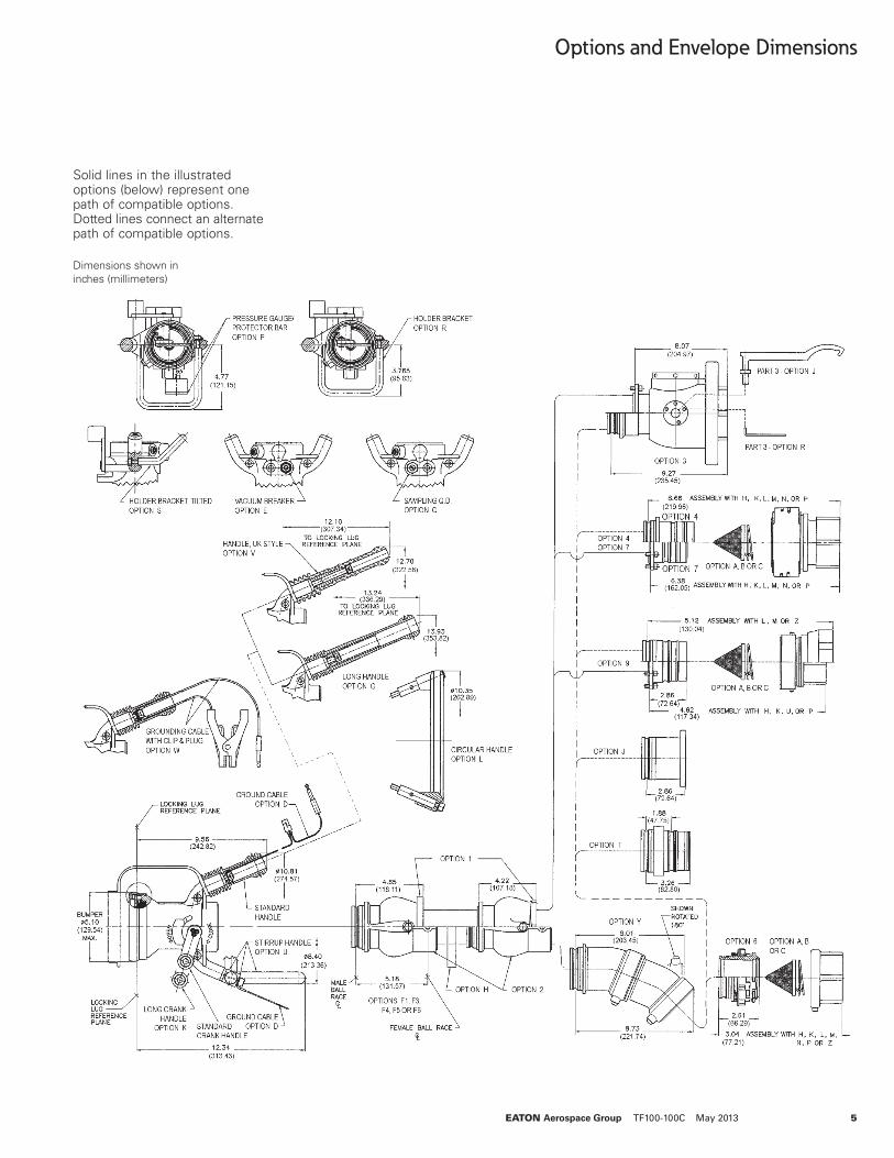
Options and Envelope Dimensions
Dimensions shown in inches (millimeters)
Solid lines in the illustrated options (below) represent one path of compatible options. Dotted lines connect an alternate path of compatible options.

Copyright © 2013 EatonAll Rights ReservedForm No. TF100-100CMay 2013
Eaton Aerospace Group 9650 Jeronimo Road Irvine, California 92618 Phone: (949) 452 9500 Fax: (949) 452 9555 www.eaton.com/aerospace
EatonAerospace GroupFluid & Electrical Distribution Division9650 Jeronimo RoadIrvine, California 92618Phone: (949) 452 9500Fax: (949) 452 9992E-mail: [email protected]