Carl J. Larosche, PE
39
Evaluation of Existing Structures Using ACI 562 Carl J. Larosche, PE
Transcript of Carl J. Larosche, PE
Evaluation of Existing Structures Using ACI 562
Carl J. Larosche, PE

Air Force Base – Academic Center
Historic Structure
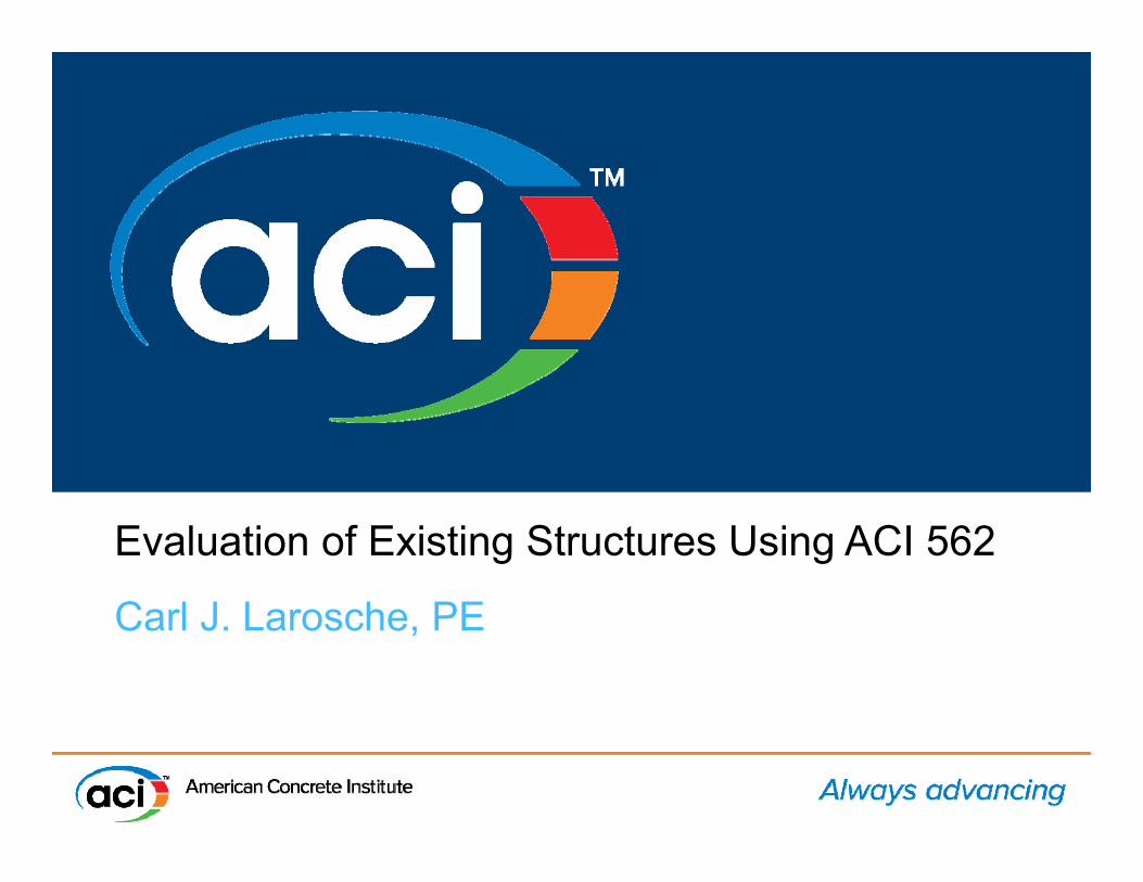
Academic BuildingAcademic Building
• Built in the 1930s• New HVAC system
October 2011
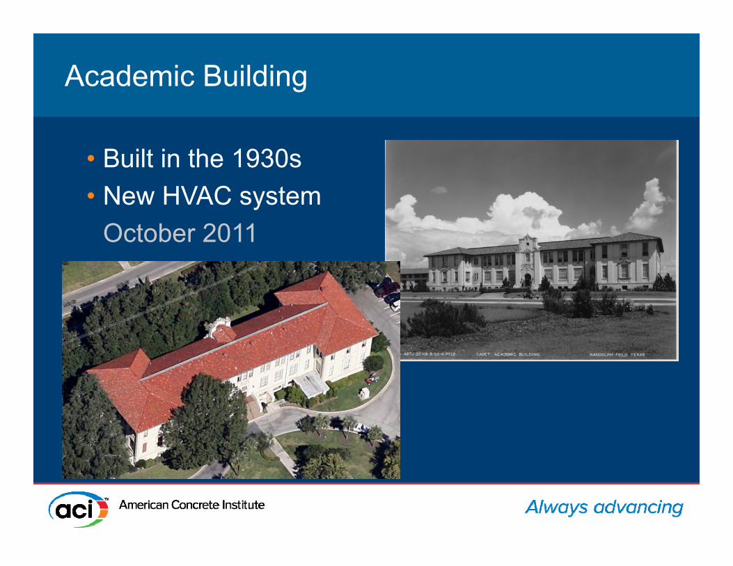
Requirements for Structural EvaluationRequirements for Structural Evaluation
• 6.1.1 - A structural evaluation shall comprise a structural assessment, structural analysis, or both.
• 6.1.2 – “A structural evaluation shall be performed if, during the preliminary evaluation, as described in Section 4.3, it is determined that an existing member, portions of a structure, or entire structure exhibit signs of deterioration, structural deficiency, …...”

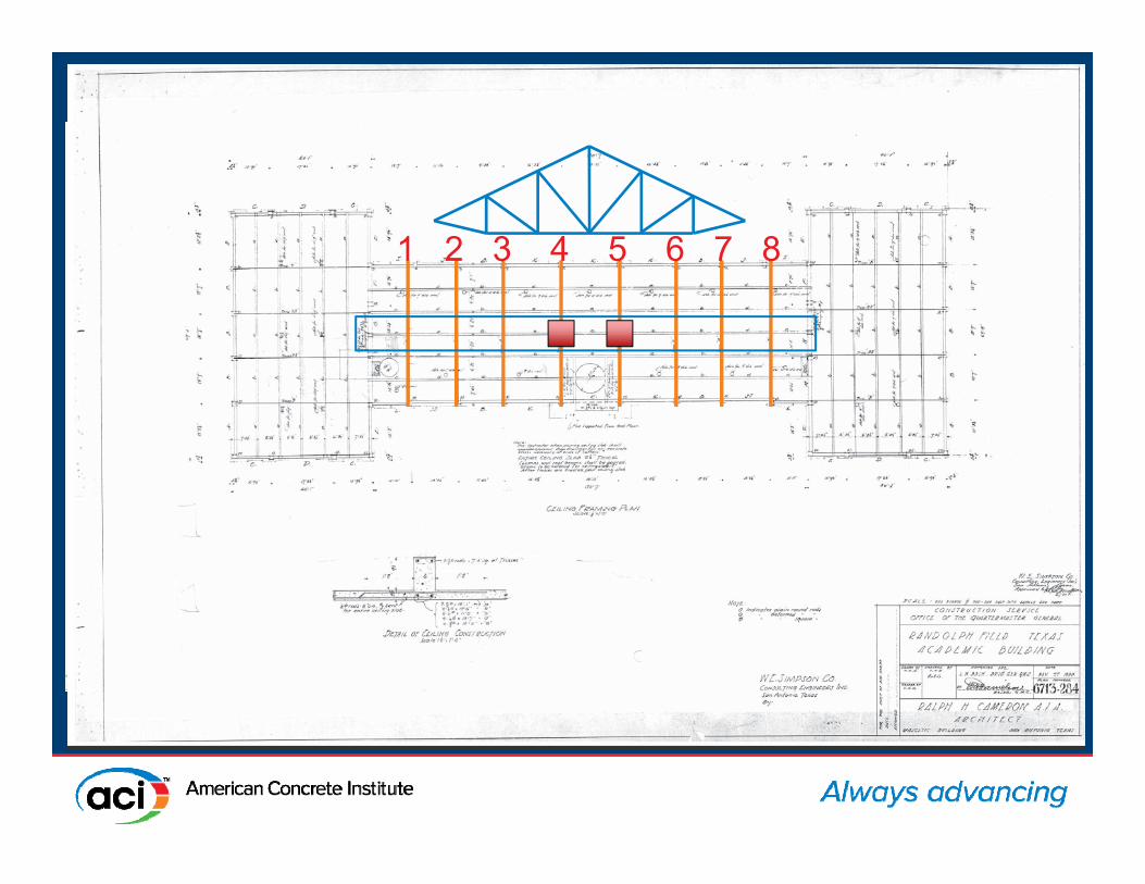
1 2 3 4 5 6 7 8

Visual AssessmentVisual Assessment
• 6.1.3 A structural evaluation shall be performed when there is a reason to question the design strength of the member or structure and insufficient information is available to determine if a member, portion, or all of the existing structure is capable of supporting existing or new design loads.

Structural Evaluation – Analysis Structural Evaluation – Analysis
• 6.2.3 - If an analysis is required, the structural assessment shall document the requirements of 6.2.2 and (a) through (c).
(a) As-measured structural member section properties and dimensions.
(b) The presence and effect of any alterations to the structural system.
(c) Loads, occupancy, or usage different from the original design.
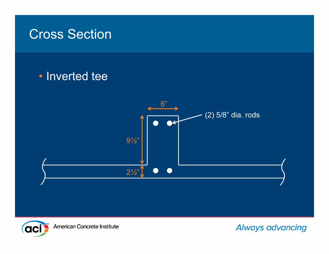
Cross SectionCross Section
• Inverted tee
(2) 5/8” dia. rods6”
9½”
2½”
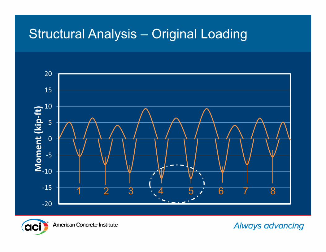
Structural Analysis – Original LoadingStructural Analysis – Original Loading
‐20
‐15
‐10
‐5
0
5
10
15
20
Mom
ent (kip‐ft)
1 2 3 4 5 6 7 8
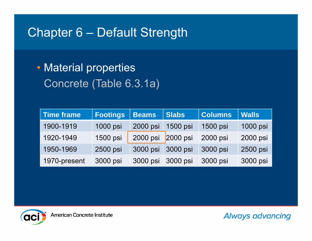
Chapter 6 – Default StrengthChapter 6 – Default Strength
• Material propertiesConcrete (Table 6.3.1a)
Time frame Footings Beams Slabs Columns Walls1900-1919 1000 psi 2000 psi 1500 psi 1500 psi 1000 psi1920-1949 1500 psi 2000 psi 2000 psi 2000 psi 2000 psi1950-1969 2500 psi 3000 psi 3000 psi 3000 psi 2500 psi1970-present 3000 psi 3000 psi 3000 psi 3000 psi 3000 psi

Chapter 6 – Default StrengthChapter 6 – Default Strength
• Material propertiesSteel (Table 6.3.1b)Time frame Grade 33 40 50 60 65 70 75
Fy,min (ksi) 33 40 50 60 65 70 70Ft,min (ksi) 55 70 80 90 75 80 100
1911-1959 X X X — X — —1959-1966 X X X X X X X1966-1972 — X X X X X —1972-1974 — X X X X X —1974-1987 — X X X X X —1987-present — X X X X X —
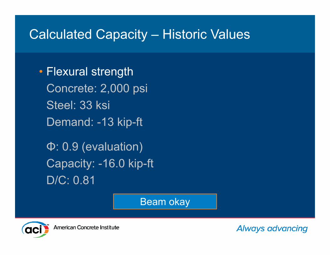
Calculated Capacity – Historic ValuesCalculated Capacity – Historic Values
• Flexural strengthConcrete: 2,000 psiSteel: 33 ksiDemand: -13 kip-ft
Φ: 0.9 (evaluation)Capacity: -16.0 kip-ftD/C: 0.81
Beam okay
1 2 3 4 5 6 7 8

Structural Analysis – Revised LoadingStructural Analysis – Revised Loading
‐20
‐15
‐10
‐5
0
5
10
15
20
Mom
ent (kip‐ft)
1 2 3 4 5 6 7 8

Calculated Capacity – Historic ValuesCalculated Capacity – Historic Values
• Flexural strengthConcrete: 2,000 psiSteel: 33 ksiDemand: -19.8 kip-ft
Φ: 0.9 (evaluation)Capacity: -16.0 kip-ftD/C: 1.24
Strengthen beam

Determine Material Strength (Testing)Determine Material Strength (Testing)
• Concrete cores
• §6.4.3-equivalent specified concrete strength
• Measured dimensions of beam

Determine Material Strength (Testing)Determine Material Strength (Testing)
• Steel coupons
• §6.4.6-equivalent specified yield strength (reinf.).
• Measured locations of bars
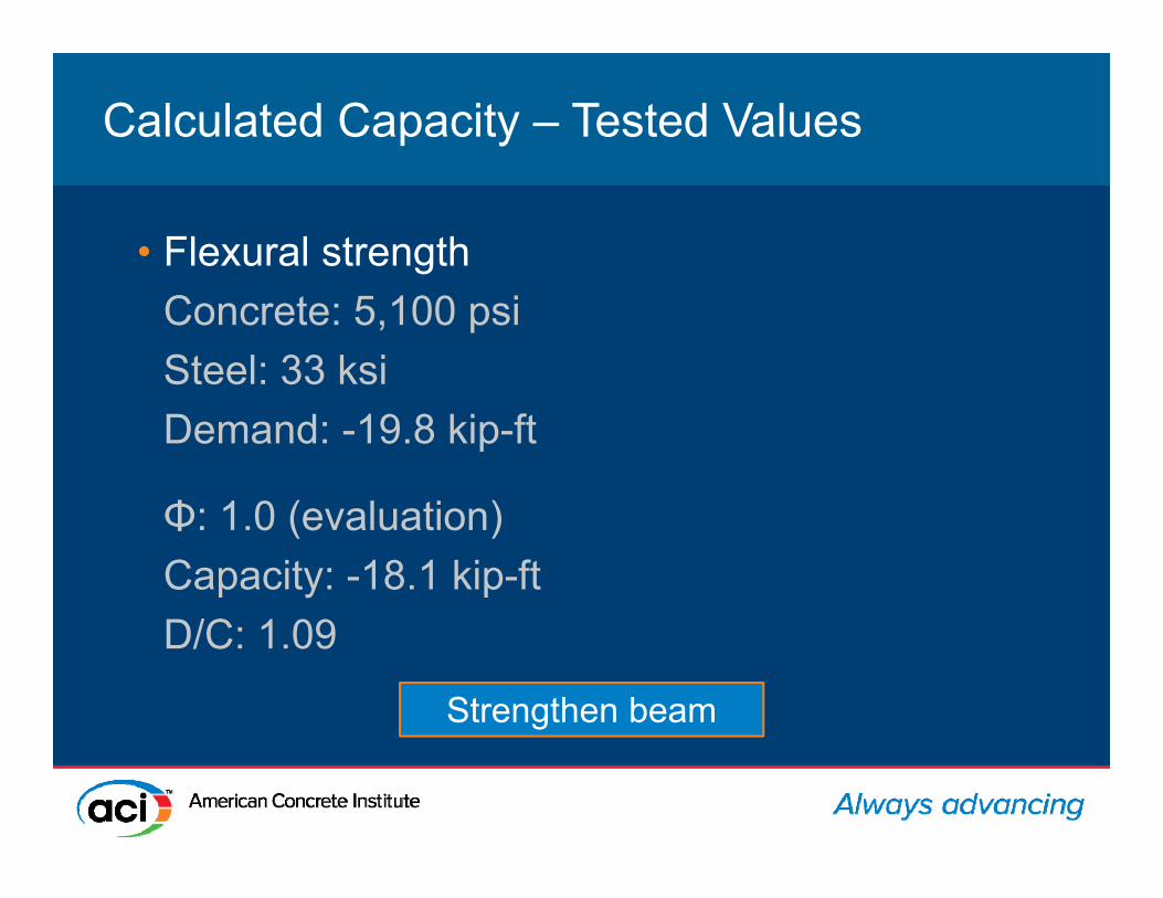
Calculated Capacity – Tested ValuesCalculated Capacity – Tested Values
• Flexural strengthConcrete: 5,100 psiSteel: 33 ksiDemand: -19.8 kip-ft
Φ: 1.0 (evaluation)Capacity: -18.1 kip-ftD/C: 1.09
Strengthen beam

RepairRepair
• Flexural strengthConcrete: 5,100 psiSteel: 33 ksiDemand: -19.8 kip-ft
6”
9½”
2½”
(2) layers of FRP

RepairRepair
• Flexural strengthΦ: 0.9 (design)Demand: -19.8 kip-ftCapacity: -37 kip-ftD/C: 0.54 6”
9½”
2½”
(2) layers of FRP

External Reinforcing SystemsExternal Reinforcing Systems
• 5.5.1 For repairs achieved with unprotected external reinforcing systems, the required strength U of a structure without repair shall be at least equal to the effects of factored loads in Eq. (5.5.1).
Uex ³ 1.2D + 0.5L + Ak + 0.2S (5.5.1)
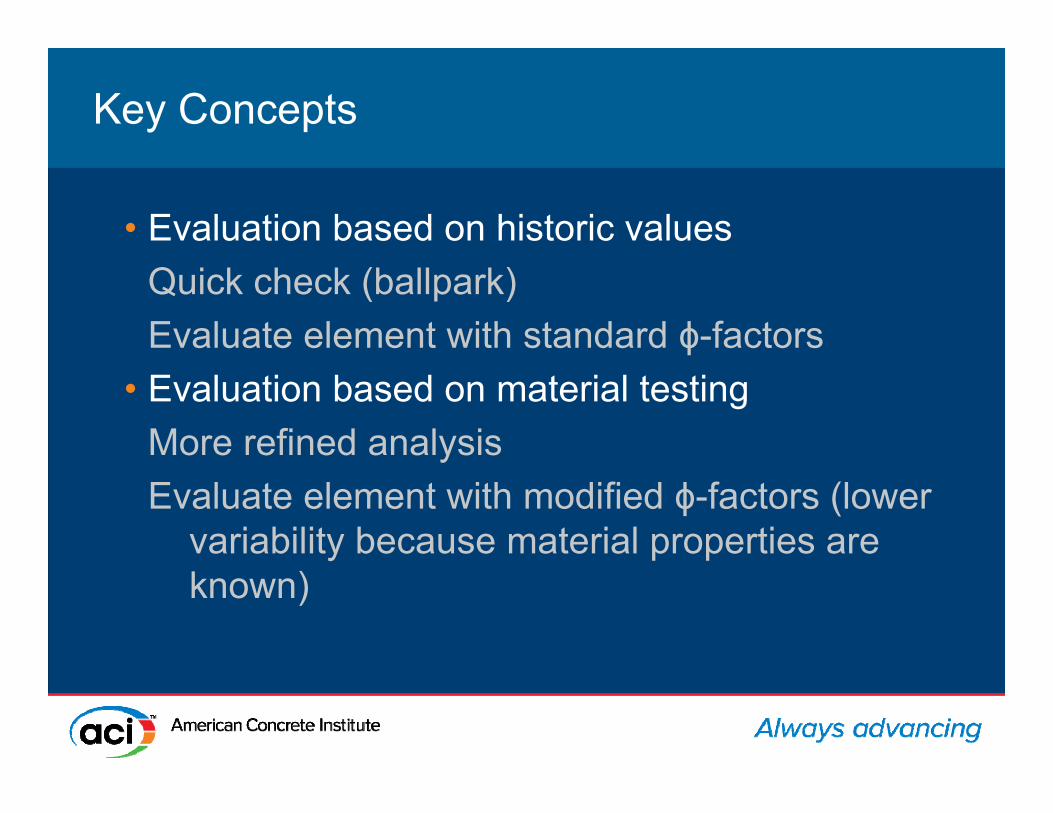
Key ConceptsKey Concepts
• Evaluation based on historic valuesQuick check (ballpark)Evaluate element with standard ϕ-factors
• Evaluation based on material testingMore refined analysisEvaluate element with modified ϕ-factors (lower
variability because material properties are known)
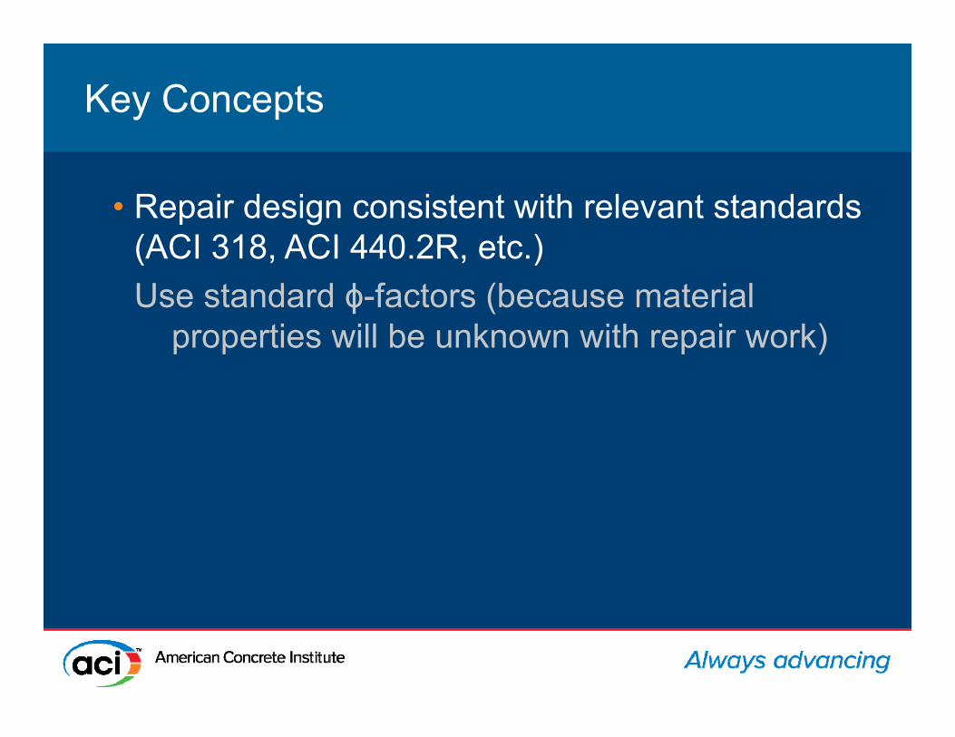
Key ConceptsKey Concepts
• Repair design consistent with relevant standards (ACI 318, ACI 440.2R, etc.)Use standard ϕ-factors (because material
properties will be unknown with repair work)
Turner-Roberts Recreation Center
New Structure

Project BackgroundProject Background
• Construction in 2008• 7,700 sf joint-use facility• Reinforced-concrete beams,
drilled piers, and steel joist roof
• Indoor gymnasium, multi-purpose rooms, weight room, and other rooms
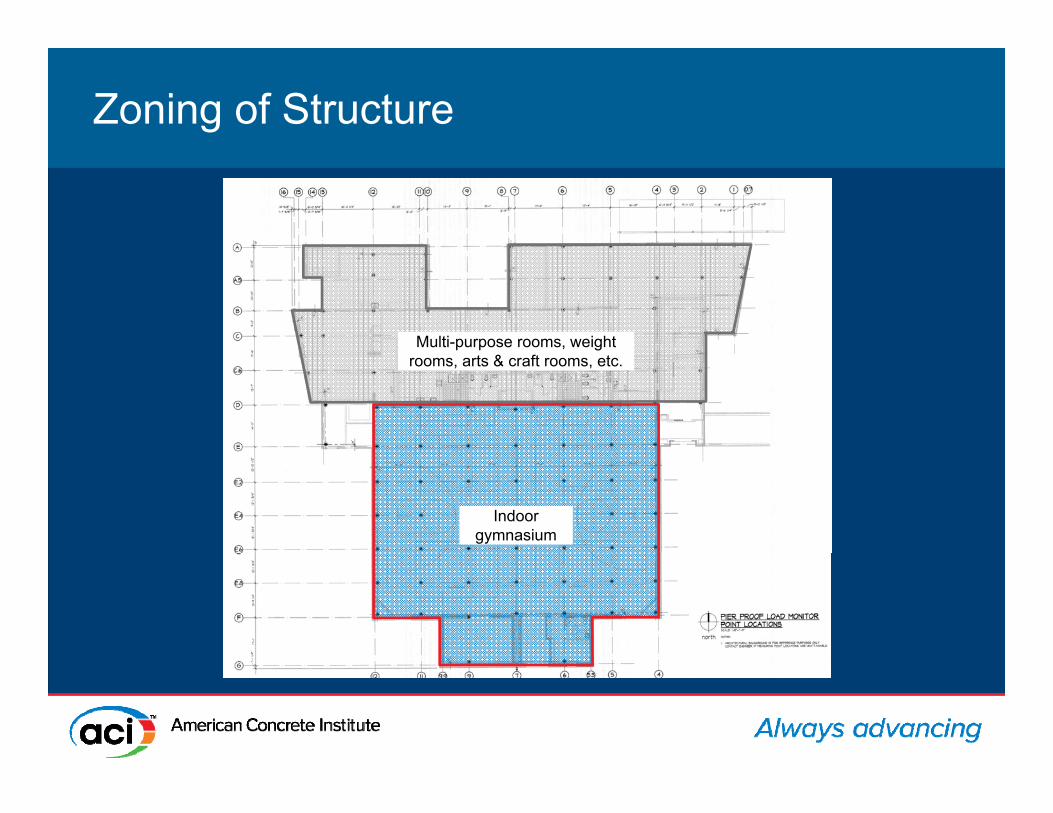
Zoning of StructureZoning of Structure
Indoor gymnasium
Multi-purpose rooms, weight rooms, arts & craft rooms, etc.
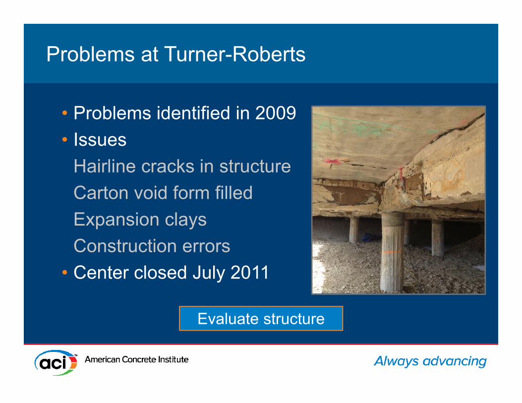
Problems at Turner-RobertsProblems at Turner-Roberts
• Problems identified in 2009• Issues
Hairline cracks in structureCarton void form filledExpansion claysConstruction errors
• Center closed July 2011
Evaluate structure

Evaluation Approaches for Existing StructuresEvaluation Approaches for Existing Structures
• Analytical (sectional analysis based on construction drawings)
• Experimental (load test)ACI 437

Demolition of StructureDemolition of Structure
Owner directed demolition of
this area
Load test this area

562 Load Test Procedures – Two Types562 Load Test Procedures – Two Types
• MonotonicApply load in four equal increments
and measure responseHold load for 24 hoursMeasure response and unload loadMeasure final response
• Acceptance criteriaEvidence of failureMaximum and residual deflections

Load Test ProceduresLoad Test Procedures
• Cyclic
• Acceptance criteriaEvidence of failureDeviation from linearity and permanency ratio
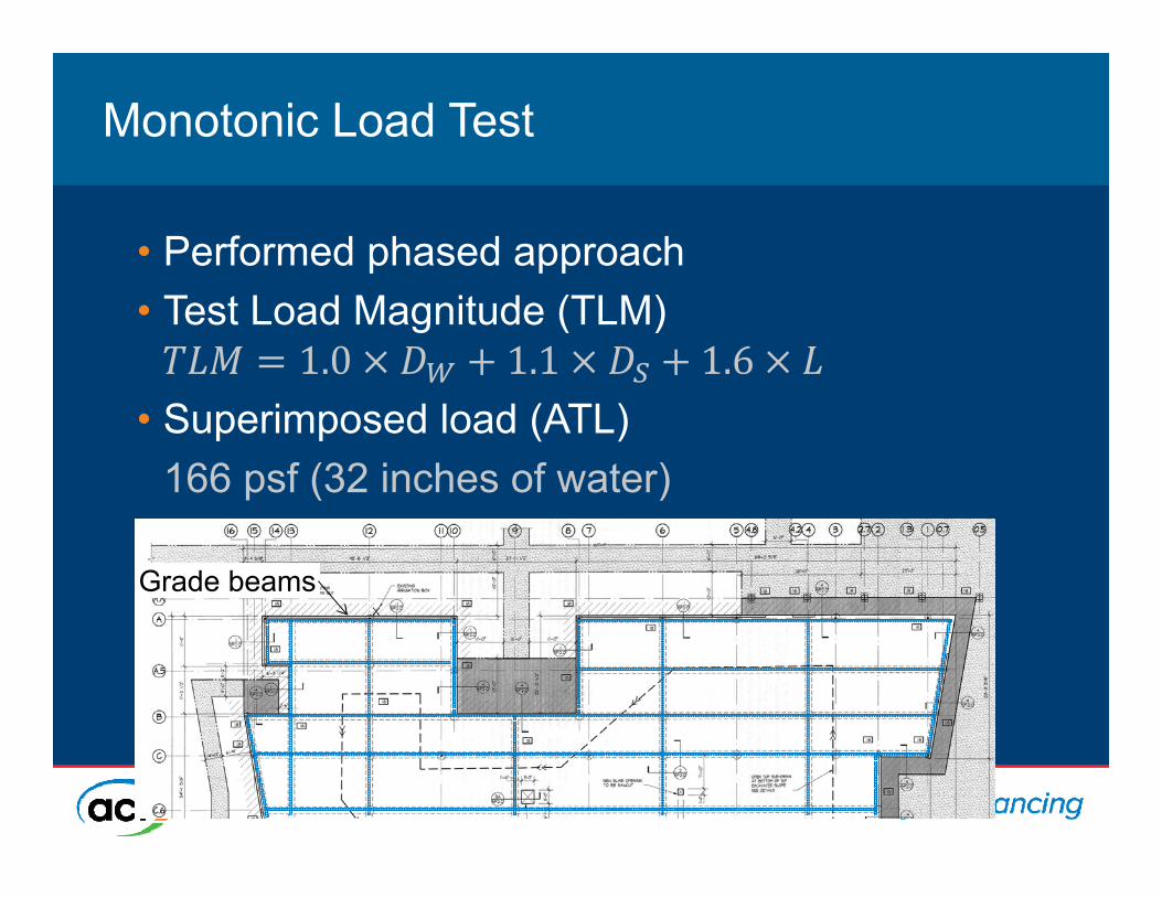
Monotonic Load TestMonotonic Load Test
• Performed phased approach• Test Load Magnitude (TLM)
• Superimposed load (ATL)166 psf (32 inches of water)
Grade beams
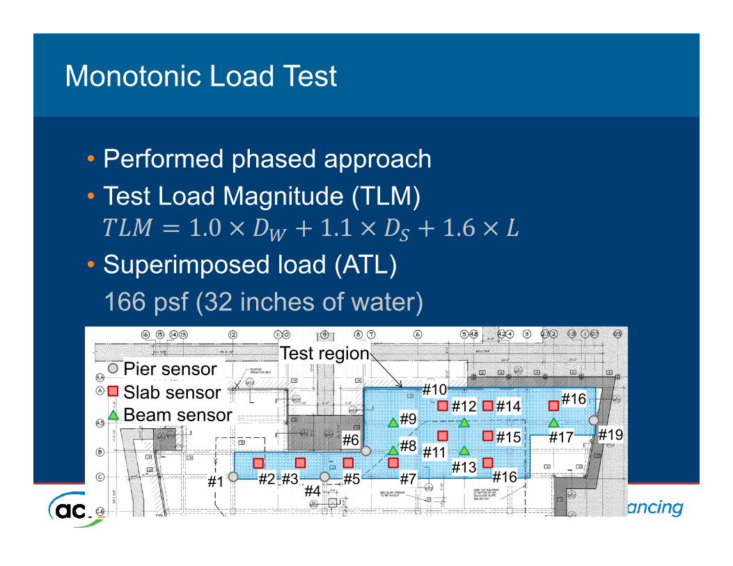
Monotonic Load TestMonotonic Load Test
• Performed phased approach• Test Load Magnitude (TLM)
• Superimposed load (ATL)166 psf (32 inches of water)
Test region
#1 #4
Pier sensorSlab sensorBeam sensor
#19#6
#3#2 #5 #7
#8
#9
#10
#11#13
#12 #14
#15
#16
#16
#17

Load TestLoad Test
Loading increments

0
40
80
120
160
200
0.00 0.01 0.02 0.03 0.04 0.05 0.06
Applied load
(psf)
Measured deflection (in.)
Behavior During Loading - LinearBehavior During Loading - Linear
Slab
Pier
Grade beam
Maximum is less than ACI criteria &
no cracks were identified
0
40
80
120
160
200
0.00 0.01 0.02 0.03 0.04 0.05 0.06
Applied load
(psf)
Measured deflection (in.)
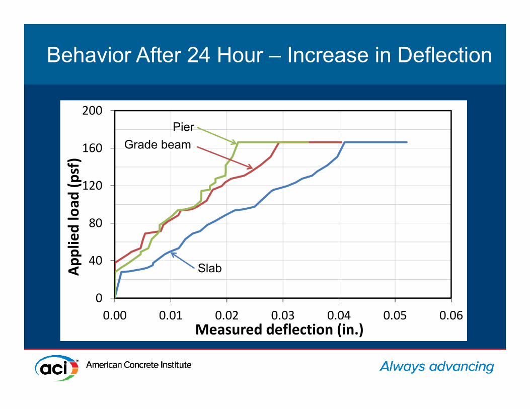
Behavior After 24 Hour – Increase in DeflectionBehavior After 24 Hour – Increase in Deflection
Slab
PierGrade beam

0
40
80
120
160
200
0.00 0.01 0.02 0.03 0.04 0.05 0.06
Applied load
(psf)
Measured deflection (in.)
Behavior During UnloadingBehavior During Unloading
Slab
PierGrade beam
Did not satisfy residual criterion

Key ConceptsKey Concepts
• Monotonic testing is essentially a proof testSlower to perform (24-hr hold)Generally easy to perform (water, sand, etc.)Criteria is based on deflections
• Cyclic testing is more of a performance standardFaster to perform with hydraulics (no 24-hr hold)Can be difficult to perform (hydraulics need to
react against something)Criteria is based on stiffness

Thank youFor the most up-to-date information please
visit the American Concrete Institute at:www.concrete.org