Carel pRack Koelcentrales
80
pRack pR100 Compressor rack controller User manual Integrated Control Solutions & Energy Savings
Transcript of Carel pRack Koelcentrales
+030xxx pRack pR100– rel 1.0 – xx/xx/2009 1
pRack pR100 Compressor rack controller
User manual
I n t e g r a t e d C o n t r o l S o l u t i o n s & E n e r g y S a v i n g s

+030xxx pRack pR100– rel 1.0 – xx/xx/2009 2

+0300011EN pRack pR100– rel 1.0 – 10/02/2010
IMPORTANT
CAREL bases the development of its products on decades of experience in HVAC, on the continuous investments in technological innovations to products, procedures and strict quality processes with in-circuit and functional testing on 100% of its products, and on the most innovative production technology available on the market. CAREL and its subsidiaries nonetheless cannot guarantee that all the aspects of the product and the software included with the product respond to the requirements of the final application, despite the product being developed according to start-of-the-art techniques. The customer (manufacturer, developer or installer of the final equipment) accepts all liability and risk relating to the configuration of the product in order to reach the expected results in relation to the specific final installation and/or equipment. CAREL may, based on specific agreements, act as a consultant for the positive commissioning of the final unit/application, however in no case does it accept liability for the correct operation of the final equipment/system.
The CAREL product is a state-of-the-art product, whose operation is specified in the technical documentation supplied with the product or can be downloaded, even prior to purchase, from the website www.CAREL.com. Each CAREL product, in relation to its advanced level of technology, requires setup / configuration / programming / commissioning to be able to operate in the best possible way for the specific application. The failure to complete such operations, which are required/indicated in the user manual, may cause the final product to malfunction; CAREL accepts no liability in such cases. Only qualified personnel may install or carry out technical service on the product. The customer must only use the product in the manner described in the documentation relating to the product. In addition to observing any further warnings described in this manual, the following warnings must be heeded for all CAREL products: Prevent the electronic circuits from getting wet. Rain, humidity and all types of
liquids or condensate contain corrosive minerals that may damage the electronic circuits. In any case, the product should be used or stored in environments that comply with the temperature and humidity limits specified in the manual.
Do not install the device in particularly hot environments. Too high temperatures may reduce the life of electronic devices, damage them and deform or melt the plastic parts. In any case, the product should be used or stored in environments that comply with the temperature and humidity limits specified in the manual.
Do not attempt to open the device in any way other than described in the manual.
Do not drop, hit or shake the device, as the internal circuits and mechanisms may be irreparably damaged.
Do not use corrosive chemicals, solvents or aggressive detergents to clean the device.
Do not use the product for applications other than those specified in the technical manual.
All of the above suggestions likewise apply to the controllers, serial boards, programming keys or any other accessory in the CAREL product portfolio. CAREL adopts a policy of continual development. Consequently, CAREL reserves the right to make changes and improvements to any product described in this document without prior warning. The technical specifications shown in the manual may be changed without prior warning. The liability of CAREL in relation to its products is specified in the CAREL general contract conditions, available on the website www.CAREL.com and/or by specific agreements with customers; specifically, to the extent where allowed by applicable legislation, in no case will CAREL, its employees or subsidiaries be liable for any lost
earnings or sales, losses of data and information, costs of replacement goods or services, damage to things or people, downtime or any direct, indirect, incidental, actual, punitive, exemplary, special or consequential damage of any kind whatsoever, whether contractual, extra-contractual or due to negligence, or any other liabilities deriving from the installation, use or impossibility to use the product, even if CAREL or its subsidiaries are warned of the possibility of such damage. DISPOSAL
INFORMATION FOR USERS ON THE CORRECT HANDLING OF WASTE ELECTRICAL AND ELECTRONIC EQUIPMENT (WEEE) In reference to European Union directive 2002/96/EC issued on 27 January 2003 and the related national legislation, please note that: WEEE cannot be disposed of as municipal waste and such waste must be
collected and disposed of separately; the public or private waste collection systems defined by local legislation must
be used. In addition, the equipment can be returned to the distributor at the end of its working life when buying new equipment;
the equipment may contain hazardous substances: the improper use or incorrect disposal of such may have negative effects on human health and on the environment;
the symbol (crossed-out wheeled bin) shown on the product or on the packaging and on the instruction sheet indicates that the equipment has been introduced onto the market after 13 August 2005 and that it must be disposed of separately;
in the event of illegal disposal of electrical and electronic waste, the penalties are specified by local waste disposal legislation.
KEY TO THE ICONS
NOTE: to bring attention to a very important subject; in particular, regarding the practical use of the various functions of the product.
IMPORTANT: to bring critical issues regarding the use of the pRack PR100 to the attention of the user. TUTORIAL: some simple examples to accompany the user in configuring the most common settings.

+0300011EN pRack pR100– rel 1.0 – 10/02/2010 4

+0300011EN pRack pR100– rel 1.0 – 10/02/2010 5
CONTENTS 1. INTRODUCTION......................................................................................................................................................................................................................6
1.1 Main features .....................................................................................................................................................................................................................6 1.2 Components and accessories ........................................................................................................................................................................................6 1.3 System configurations and input and output configuration ...................................................................................................................................7
2. HARDWARE FEATURES AND INSTALLATION...................................................................................................................................................................9 2.2 Description of the pRack pR100 S, M, L, XL boards................................................................................................................................................12
3. INSTALLATION.......................................................................................................................................................................................................................18 3.1 General installation instructions ..................................................................................................................................................................................18 3.2 Power supply....................................................................................................................................................................................................................18 3.3 Connecting the analogue inputs .................................................................................................................................................................................19 3.4 Connecting the digital inputs .......................................................................................................................................................................................20 3.5 Connecting the analogue outputs...............................................................................................................................................................................21 3.6 Connecting the digital outputs.....................................................................................................................................................................................21 3.7 pLAN electrical connections .........................................................................................................................................................................................22
4. START UP.................................................................................................................................................................................................................................23 4.1 Starting the first time ......................................................................................................................................................................................................23
5. USER INTERFACE ...................................................................................................................................................................................................................25 5.1 Graphic terminal..............................................................................................................................................................................................................25 5.2 Description of the display .............................................................................................................................................................................................25 5.3 Password ...........................................................................................................................................................................................................................25 5.4 Description of the menu ...............................................................................................................................................................................................26
6. FUNCTIONS............................................................................................................................................................................................................................28 6.1 Unit On-Off.......................................................................................................................................................................................................................28 6.2 Control ...............................................................................................................................................................................................................................28 6.3 Compressors ....................................................................................................................................................................................................................30 6.4 Fans ....................................................................................................................................................................................................................................35 6.5 Energy saving ...................................................................................................................................................................................................................36 6.6 Accessory functions ........................................................................................................................................................................................................37 6.7 Settings ..............................................................................................................................................................................................................................41 6.8 Managing the default values ........................................................................................................................................................................................41
7. PARAMETERS TABLE .............................................................................................................................................................................................................42 8. ALARMS ...................................................................................................................................................................................................................................63
8.1 Alarm management........................................................................................................................................................................................................63 8.2 Compressor alarms.........................................................................................................................................................................................................63 8.3 Pressure and prevent alarms........................................................................................................................................................................................64
9. Supervisory and commissioning systems........................................................................................................................................................................66 10. UPDATING THE SOFTWARE ...............................................................................................................................................................................................67 11. Appendix..................................................................................................................................................................................................................................68
A.1 System configurations available ..................................................................................................................................................................................68 A.2 System configurations with more than one pLAN board......................................................................................................................................72 A.3 Example of configuring a system with 2 suction and condenser lines using the Wizard ..............................................................................73 A.4 Alarm table .......................................................................................................................................................................................................................75
+0300011EN pRack pR100– rel 1.0 – 10/02/2010 6
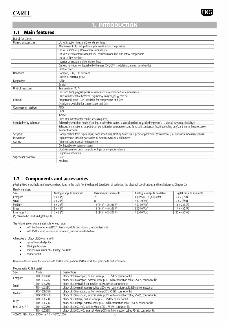
1. INTRODUCTION 1.1 Main features List of functions: Main characteristics Up to 2 suction lines and 2 condenser lines Management of scroll, piston, digital scroll, screw compressors Up to 12 scroll or piston compressors per line Up to 2 screw compressors per line, maximum one line with screw compressors Up to 16 fans per line Inverter on suction and condenser lines Generic functions configurable by the user (ON/OFF, modulation, alarms, time bands) Heat recovery Hardware Compact, S, M, L, XL versions Built-in or external pGD1 Languages Italian English Unit of measure Temperature: °C, °F Pressure: barg, psig (all pressure values are also converted to temperature) Date format settable between: dd/mm/yy, mm/dd/yy, yy.mm.dd Control Proportional band (P, PI) available for compressors and fans Dead zone available for compressors and fans Compressor rotation FIFO LIFO Timed Fixed (the on/off order can be set as required) Scheduling by calendar Scheduling available: heating/cooling, 4 daily time bands, 5 special periods (e.g.: closing period), 10 special days (e.g.: holidays) Schedulable functions: set point compensation for compressors and fans, split condenser (heating/cooling only), anti noise, heat recovery,
generic functions Set point Compensation from digital input, from scheduling, floating based on supervisor parameter (compressors) or outside temperature (fans) Prevention High pressure, including activation of heat recovery or ChillBooster Alarms Automatic and manual management Configurable compressor alarms Double signal on digital outputs for high or low priority alarms Log from application Supervisor protocol Carel Modbus
1.2 Components and accessories pRack pR100 is available in 5 hardware sizes, listed in the table (for the detailed description of each size, the electrical specifications and installation see Chapter 2.):
Hardware sizes: Size Analogue inputs available Digital inputs available Analogue outputs available Digital outputs available Compact 2 + 6 (*) 2 1 (PWM) + 1 (0-10 Vdc) 5 + 2 (SSR) Small 3 + 2 (*) 8 4 (0-10 Vdc) 6 + 2 (SSR) Medium 6 + 2 (*) 12 (24 V) + 2 (230 V) 4 (0-10 Vdc) 11 + 2 (SSR) Large 6 + 4 (*) 14 (24 V) + 4 (230 V) 6 (0-10 Vdc) 14 + 4 (SSR) Extra large NO 6 + 2 (*) 12 (24 V) + 2 (230 V) 4 (0-10 Vdc) 25 + 4 (SSR) (*) can also be used as digital inputs The following versions are available for each size:
with built-In or external PGD1 terminal, white background , without terminal with RS485 serial interface incorporated, without serial interface
All models of pRack pR100 come with:
optically-isolated pLAN black plastic cover maximum number of SSR relays available connector kit
Below are the codes of the models with RS485 serial, without RS485 serial, the spare parts and accessories. Models with RS485 serial: Size Code Description
PRK100X3B0 pRack pR100 compact, built-in white pGD1, RS485, connector kit Compact PRK100X3BK pRack pR100 compact, external white pGD1 with connection cable, RS485, connector kit. PRK100S3B0 pRack pR100 small, built-in white pGD1, RS485, connector kit Small PRK100S3BK pRack pR100 small, external white pGD1 with connection cable, RS485, connector kit PRK100M3B0 pRack pR100 medium, built-in white pGD1, RS485, connector kit Medium PRK100M3BK pRack pR100 medium, external white pGD1 with connection cable, RS485, connector kit PRK100L3B0 pRack pR100 large, built-in white pGD1, RS485, connector kit Large PRK100L3BK pRack pR100 large, external white pGD1 with connection cable, RS485, connector kit PRK100Z3B0 pRack pR100 XL NO, built-in white pGD1, RS485, connector kit Extra large NO PRK100Z3BK pRack pR100 XL NO, external white pGD1 with connection cable, RS485, connector kit
+0300011EN pRack pR100– rel 1.0 – 10/02/2010 7
PRK100S3AK pRack pR100 XL NO, external white pGD1 with connection cable, RS485, connector kit
Models without RS485 serial: Size Code Description
PRK100S3A0 pRack pR100 small, built-in white pGD1, connector kit Small PRK100S3AK pRack pR100 small, external white pGD1 with connection cable, connector kit PRK100M3A0 pRack pR100 medium, built-in white pGD1, connector kit Medium PRK100M3AK pRack pR100 medium, external white pGD1 with connection cable, connector kit PRK100L3A0 pRack pR100 large, built-in white pGD1, connector kit Large PRK100L3AK pRack pR100 large, external white pGD1 with connection cable, connector kit PRK100Z3A0 pRack pR100 XL NO, built-in white pGD1, connector kit Extra large NO PRK100Z3A0 pRack pR100 XL NO, external white pGD1 with connection cable, connector kit
Spare parts: Code Description PRK100X0B0 pRack pR100 compact, without terminal, RS485, connector kit PRK100S0A0 pRack pR100 small, without terminal, connector kit. PRK100M0A0 pRack pR100 medium, without terminal, connector kit. PRK100L0A0 pRack pR100 large, without terminal, connector kit. PRK100Z0A0 pRack pR100 XL, without terminal, connector kit.
Accessories: Code Description PGD1RK0FX0 PGD1 user terminal for pRack pR100 CONV0/10A0 Module for converting a PWM output to a linear 0 to 10 V and 4 to 20 mA analogue output CONVONOFF0 Module for converting a 0 to 10 V analogue output to an SPDT digital output PCOS004850 RS485 serial connection card CVSTDUTLF0 USB/RS485 serial converter with telephone connector CVSTDUMOR0 USB/RS485 serial converter with 3 pin terminal PCOSO0AKY0 Smart key (programming key) PCOSO0AKC0 PC Smart Key USB converter S90CONN002 Terminal connection cable l=0.8 m S90CONN000 Terminal connection cable l=1.5 m S90CONN001 Terminal connection cable l=3 m SPKT*R* e SPKC00* 0 to 5 Vdc ratiometric pressure probes SPK*C*, SPK1*, SPK2*, SPK3* 4 to 20 mA active pressure probes NTC* NTC temperature probes -50T90°C NTC*HT* NTC temperature probes -0T150°C
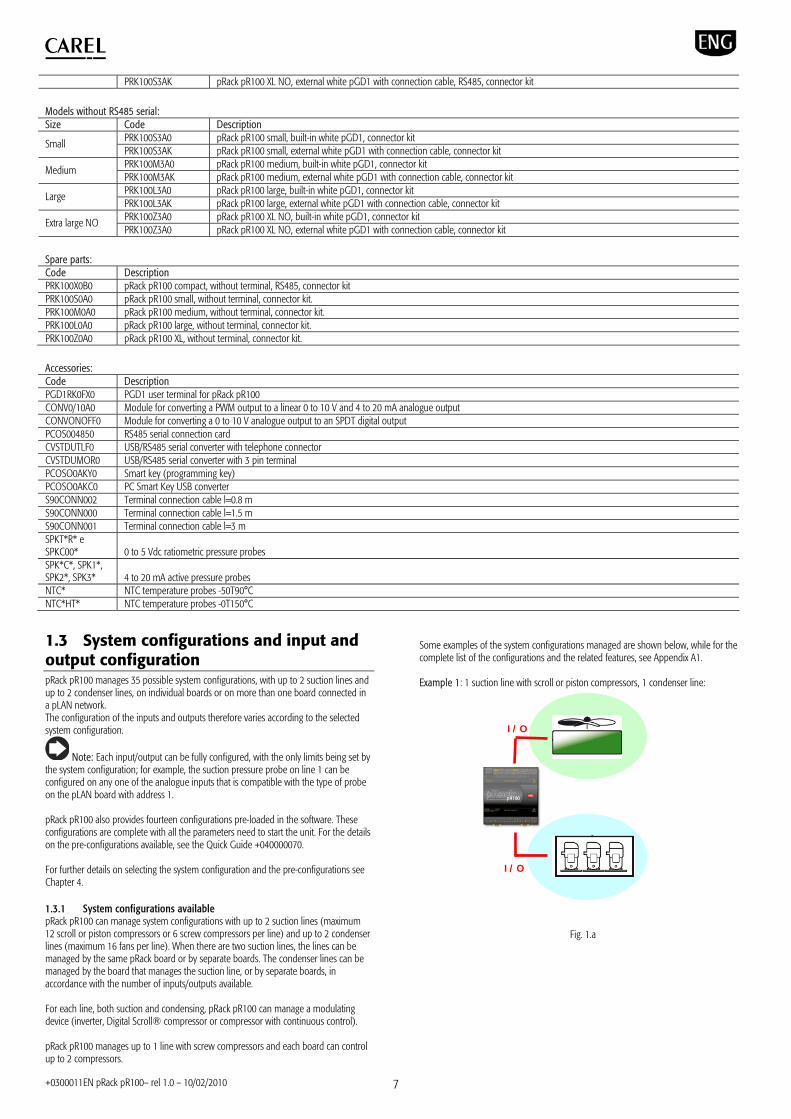
1.3 System configurations and input and output configuration pRack pR100 manages 35 possible system configurations, with up to 2 suction lines and up to 2 condenser lines, on individual boards or on more than one board connected in a pLAN network. The configuration of the inputs and outputs therefore varies according to the selected system configuration.
Note: Each input/output can be fully configured, with the only limits being set by the system configuration; for example, the suction pressure probe on line 1 can be configured on any one of the analogue inputs that is compatible with the type of probe on the pLAN board with address 1. pRack pR100 also provides fourteen configurations pre-loaded in the software. These configurations are complete with all the parameters need to start the unit. For the details on the pre-configurations available, see the Quick Guide +040000070. For further details on selecting the system configuration and the pre-configurations see Chapter 4. 1.3.1 System configurations available pRack pR100 can manage system configurations with up to 2 suction lines (maximum 12 scroll or piston compressors or 6 screw compressors per line) and up to 2 condenser lines (maximum 16 fans per line). When there are two suction lines, the lines can be managed by the same pRack board or by separate boards. The condenser lines can be managed by the board that manages the suction line, or by separate boards, in accordance with the number of inputs/outputs available. For each line, both suction and condensing, pRack pR100 can manage a modulating device (inverter, Digital Scroll® compressor or compressor with continuous control). pRack pR100 manages up to 1 line with screw compressors and each board can control up to 2 compressors.
Some examples of the system configurations managed are shown below, while for the complete list of the configurations and the related features, see Appendix A1. Example 1: 1 suction line with scroll or piston compressors, 1 condenser line:
Fig. 1.a
I/O
I/O

+0300011EN pRack pR100– rel 1.0 – 10/02/2010 8
Example 2: 2 suction lines on the same board with scroll or piston compressors, 1 condenser line:
Fig. 1.b
Example 3: 2 suction lines on the same board with scroll or piston compressors, 2 condenser lines on the same board:
Fig. 1.c
Example 4: 2 suction lines on separate boards (scroll or piston compressors), 2 condenser lines (one for each suction line board)
Fig. 1.d
Example 5: 2 suction lines on separate boards with scroll or piston compressors, 2 condenser lines on separate boards:
Fig. 1.e
I/O
I/O I/O
pLAN
I/O
I/O
I/O I/O
pLAN
I/O
pLAN
I/O
I/O
I/O
I/O
I/O
I/O
I/O

+0300011EN pRack pR100– rel 1.0 – 10/02/2010 9
2. HARDWARE FEATURES AND INSTALLATION 2.1 Description of the pRack pR100 Compact
Fig. 2.a 2.1.1 Meaning of the inputs/outputs on the pRack pR100 Compact board connector signal description J1-1 G 24 Vac or 36/72 Vdc power supply J1-2 G0 power supply reference J2-1 SYNC synchronicity input for phase control (G0 is the reference) J2-2 B1 universal analogue input 1 (NTC, 0 to 1 V, 0 to 5 V ratiometric, 0 to 10 V, 0 to 20 mA, 4 to 20 mA) J2-3 B2 universal analogue input 2 (NTC, 0 to 1 V, 0 to 5 V ratiometric, 0 to 10 V, 0 to 20 mA, 4 to 20 mA) J2-4 B3 universal analogue input 3 (NTC, 0/1 V, PT1000) J2-5 B4 universal analogue input 4 (NTC, 0/1 V, PT1000) J2-6 B5 universal analogue input 5 (NTC, 0 to 1 V, 0 to 5 V ratiometric, 0 to 10 V, 0 to 20 mA, 4 to 20 mA, ON/OFF) J2-7 B6 universal analogue input 6 (NTC, 0 to 1 V, 0 to 5 V ratiometric, 0 to 10 V, 0 to 20 mA, 4 to 20 mA, ON/OFF) J2-6 GND analogue input reference J2-8 +5Vref power supply for 0/5 V ratiometric probes J2-9 +VDC 21 Vdc power supply for active probes J2-10 ID1 digital input no. 1 J2-11 GND common for digital inputs and analogue inputs J3-1 C1 common for relay: 1 J3-2 --- Not used J3-3 NO1 normally open contact, relay no. 1 SSR 24 Vac/Vdc J4 6-pin telephone connector for connecting the standard user terminal J5-1 RX-/TX- RX-/TX- connector for RS485 connection to the pLAN network J5-2 RX+/TX+ RX+/TX+ connector for RS485 connection to the pLAN network J5-3 GND reference for RS485 connection to the pLAN network J6 4-pin connector for connecting the user terminal pLD (not used) J7-1 TLAN tLAN network connector J7-2 GND tLAN network connection reference J8-1 RX-/TX- RX-/TX- connector for RS485 connection to the optically-isolated “Field-bus” network J8-2 RX+/TX+ RX+/TX+ connector for RS485 connection to the optically-isolated “Field-bus” network J8-3 GND reference for RS485 connection to the optically-isolated “Field-bus” network J9-1 Y1 analogue output no. 1 PWM (for phase cutting speed controllers) J9-2 Y2 analogue output no. 2 0/10 V J9-3 GND analogue output reference J10-1 NO2 normally open contact, relay no. 2 SSR 24 Vac/Vdc J10-2 C2 common for relay: 2 J11-1 C3 common for relays: 3, 4, 5, 6, 7 J11-2 NO3 normally open contact, relay no. 3 J11-3 NO4 normally open contact, relay no. 4 J11-4 NO5 normally open contact, relay no. 5 J11-5 NO6 normally open contact, relay no. 6 J11-6 NO7 normally open contact, relay no. 7 J11-7 C3 common for relays: 3, 4, 5, 6, 7 J12-1 GND common for digital inputs and analogue inputs J12-2 B7 passive analogue input 7 (NTC, ON/OFF) J12-3 B8 passive analogue input 8 (NTC, ON/OFF)
Description of the pRack pR100 Compact board Key 1 power supply connector (G+, G0-) 24 Vac or 36 Vmin to 72 Vmax 2 “SYNC“ synchronicity inputs for phase control;
NTC, 0 to 1 V, 0 to 5 V, 0 to 20 mA, 4 to 20 mA analogue inputs ; +5 Vref to supply 5 V ratiometric probes; + VDC (+21 Vdc) for power to active probes; digital input
3 SSR digital output 24 Vac/Vdc 4 connector for pGD1 terminal and for downloading the application program 5 pLAN network connector 6 connector for pLD terminals (not used) 7 tLAN network connector (not used) 8 optically-isolated “Field-bus” serial connector 9 0 to 10 V analogue and PWM phase control outputs 10 SSR digital output 24 Vac/Vdc 11 5 A SPST digital output 12 NTC analogue inputs and digital input

+0300011EN pRack pR100– rel 1.0 – 10/02/2010 10
2.1.2 Technical specifications of the pRack pR100 Compact board Analogue inputs Analogue conversion 10-bit A/D converter embedded in CPU Maximum number 8
Type
Universal: 2 (inputs B1, B2) - CAREL NTC (-50T90°C; R/T 10 k±1% at 25°C), NTC HT0T150 °C - Voltage 0 to 1 Vdc, 0 to 10 Vdc, 0 to 5 Vdc ratiometric - Current 0 to 20 mA or 4 to 20 mA. Input resistance: 100 Universal: 2 (inputs B3, B4) - CAREL NTC (-50T90°C; R/T 10 k±1% at 25°C) NTC HT0T150 °C - Voltage 0 to 1 Vdc - PT1000 (-100T200 °C; R/T 1000 at 0°C) Universal: 2 (inputs B5, B6) - CAREL NTC (-50T90°C; R/T 10 k±1% at 25°C) NTC HT0T150 °C - Voltage 0 to 1 Vdc, 0 to 10 Vdc, 0 to 5 Vdc ratiometric - Voltage-free digital inputs, 5 mA Passive: 2 (inputs B7, B8) -CAREL NTC (-50T90°C; R/T 10k±1% at 25°C) NTC HT0T150 °C - Voltage-free digital inputs, 5 mA Selectable via software
Time constant 0.5 s Input precision ± 0.3 % of full scale Classification of the measurement circuits Category 1 (IEC EN 61010-1)
Important: the 21 Vdc available at terminal +VDC (J2) can be used to power any active probes. The maximum current is Imax=60 mA, thermally protected against short-circuits. To power the 0 to 5 Vdc ratiometric probes, use the 5V available at terminal +5Vref (J2). The maximum current is Imax=60 mA, thermally protected against short-circuits. Digital inputs Type Not optically-isolated, voltage-free contact Maximum number 6: 2 + 4 multifunction analogue inputs
Normally open (open-closed-open) 250 ms Minimum digital input impulse detection time Normally closed (closed-open-closed) 250 ms
Power supply internal Analogue outputs Type Not optically-isolated
Maximum number 2: 1 PWM phase control output (Y1) with 5V pulse of programmable duration and 1 x 0 to 10 Vdc output (Y2)
Power supply internal Precision ± 2% of full scale on Y2 Resolution 8 bit Settling time 2 s on Y2 Maximum load 1 k (10 mA) for 0 to 10 Vdc and 470 (10 mA) for PWM
Note: the synchronicity for the PWM phase control output is taken from the SYNC input and G0 (J2). Digital outputs
Important: The outputs can be divided into groups, depending on the insulation distance. The relays belonging to the same group have basic insulation between each other and therefore must have the same power supply (24 Vac or 110 to 230 Vac). Between groups there is double insulation and consequently these may have different voltages.
Group 1 (J3) Group 2 (J10) Group 3 (J11)
Makeup of the groups Type of relay Type A Available with NC and NO contacts
Type A Available with NO contacts
Type B Available with NO contacts
Features
MOSFET photovoltaic relay Operating voltage 24 Vac/Vdc Maximum power 10 W.
MOSFET photovoltaic relay Operating voltage 24 Vac/Vdc Maximum power 10 W.
SPST, 1250 VA, 250 Vac, 5 A resistive. Approval available: UL873: 1 A resistive, 1 A FLA, 6 A LRA, 250 Vac, D300 pilot duty (30,000 cycles). EN 60730-1: 1 A resistive, 1 A inductive, cosφ=0.6, 1(1) A (100,000 cycles).
Maximum number 7 Number of changeover contacts 1 (J3) Number of SSR outputs 2: outputs NO1 and NO2 (J3 and J10);
Important: the groups that the digital outputs are divided into have two common pole terminals to simplify wiring. Make sure that the current running through the common terminals does not exceed the rated current of an individual terminal, that is, 8 A. To connect the digital outputs use a cable with minimum cross-section of 1.5 mm2.
Important: the SSR digital outputs must be powered at 24 Vac/Vdc, with a maximum power of 10 W, otherwise they may be damaged.

+0300011EN pRack pR100– rel 1.0 – 10/02/2010 11
2.1.3 Electrical specifications of the pRack pR100 Compact board Isolated power supply 24 Vac +10/-15 % 50/60 Hz and 48 Vdc (36 Vmin to 72 Vmax) Maximum current P=11 W, P=14 VA, Imax=700 mA Terminal block with male/female plug-in connectors (250 Vac max, 8 A max) Cable cross-section min 0.5 mm2 – max 2.5 mm2
CPU H8SX/1651 32 bit, 50 MHz Program memory (FLASH) 2+2 MByte Data memory (SRAM) 512 Kbyte at 16 bit Parameter data memory (EEPROM) 13 Kbyte +32 kB NAND FLASH memory 32 MByte Working cycle duration 0.3 s (application of average complexity) Clock with battery Available as standard and integrated into main board Battery Lithium button battery, code CR2430, voltage 3 Vdc, dimensions 24x3 mm
2.1.4 Mechanical specifications of the pRack pR100 Compact board Physical dimensions 6 DIN modules: 105x110x60 mm
Assembly Fitted on DIN rail as per DIN 43880 and IEC EN 50022 Material technopolymer Flame retardance V2 (UL94) and 960°C (IEC 695) Ball pressure test 125 °C Resistance to creeping current 250 V
Plastic case Colour Grey RAL7016
2.1.5 Other specifications of the pRack pR100 Compact board Operating conditions -10T60 °C, 90% RH non-condensing Storage conditions -20T70 °C, 90% RH non-condensing Index of protection IP20, IP40 on the front panel only Environmental pollution 2 Class according to protection against electric shock to be integrated into Class 1 and/or 2 appliances Period of stress across the insulating parts long Type of action 1C Type of disconnection or microswitching microswitching Category of resistance to heat and fire Category D (UL94-V0) Immunity against voltage surges Category 1I Ageing characteristics (operating hours) 80,000 No. of automatic operating cycles 100,000 (EN 60730-1); 30,000 (UL 873) Software class and structure Class A Category of immunity to voltage surges (IEC EN 61000-4-5) Category 2 (IEC EN 61000-4-5)
Error at 25°C ±5.3 min/year Error in the temperature range –10T60 °C ±27 min/year Ageing < ± 5ppm (±2.7min/year) Battery duration typically 6 months (8 months maximum)
Clock
Recharge time typically 5 hours (< 8 hours maximum) 2.1.6 pRack pR100 Compact dimensions
105 60
110
Fig, 2.b
2.1.7 pRack pR100 Compact product certification UL 873 and C22.2 No. 24-93: “Temperature-indicating and regulating equipment”.

+0300011EN pRack pR100– rel 1.0 – 10/02/2010 12
2.2 Description of the pRack pR100 S, M, L, XL boards pRack pR100 S:
9 10 13 11
765 24 143 151 Fig, 2.c
pRack pR100 M:
9 10 13
7 765 54 4143 151 2
Key
1 power supply connector (G+, G0-) 2 yellow power LED and 3 status LEDs;
3 additional power supply for the terminal and 0 to 5 V ratiometric probes;
4 universal NTC, 0 to 1 V, 0 to 5 V - ratiometric, 0 to 10 V, 0 to 20 mA, 4 to 20 mA analogue inputs;
5 passive NTC, PT1000, ON/OFF analogue inputs; 6 0 to 10 V analogue outputs;
7 24 Vac/Vdc digital inputs; 8 230 Vac or 24 Vac/Vdc digital inputs;
9 display terminal connector (not used);
10 connector for pGD1 terminal and for downloading the application program 11 relay digital outputs;
12 I/O expansion board connector (not used); 13 pLAN network connector;
14 cover for inserting the supervisor and telemaintenance option (available on models PRK100*3B*);
15 cover for inserting the field card option;
Fig. 2.d pRack pR100 L:
9 10 13
7 765 5
12
11
4 4143 151 2
8
6
5
7
Fig. 2.e pRack pR100 XL
Fig. 2.f

+0300011EN pRack pR100– rel 1.0 – 10/02/2010 13
2.2.1 Meaning of the inputs/outputs on the pRack pR100 S, M, L, XL boards Version Connector Signal Description
J1-1 G +24 Vdc or 24 Vac power supply J1-2 G0 power supply reference J2-1 B1 universal analogue input 1 (NTC, 0 to 1 V, 0 to 5 V ratiometric, 0 to 10 V, 0 to 20 mA, 4 to 20 mA) J2-2 B2 universal analogue input 2 (NTC, 0 to 1 V, 0 to 5 V ratiometric, 0 to 10 V, 0 to 20 mA, 4 to 20 mA) J2-3 B3 universal analogue input 3 (NTC, 0 to 1 V, 0 to 5 V ratiometric, 0 to 10 V, 0 to 20 mA, 4 to 20 mA) J2-4 GND common for analogue inputs J2-5 +VDC 21 Vdc power supply for active probes (maximum current 200 mA) J3-1 B4 passive analogue input 4 (NTC, PT1000, ON/OFF) J3-2 BC4 common for analogue input 4 J3-3 B5 passive analogue input 5 (NTC, PT1000, ON/OFF) J3-4 BC5 common for analogue input 5 J4-1 VG power to optically-isolated analogue output, 24 Vac/Vdc J4-2 VG0 power to optically-isolated analogue output, 0 Vac/Vdc J4-3 Y1 analogue output no. 1, 0 to 10 V J4-4 Y2 analogue output no. 2, 0 to 10 V J4-5 Y3 analogue output no. 3, 0 to 10 V J4-6 Y4 analogue output no. 4, 0 to 10 V J5-1 ID1 digital input no. 1, 24 Vac/Vdc J5-2 ID2 digital input no. 2, 24 Vac/Vdc J5-3 ID3 digital input no. 3, 24 Vac/Vdc J5-4 ID4 digital input no. 4, 24 Vac/Vdc J5-5 ID5 digital input no. 5, 24 Vac/Vdc J5-6 ID6 digital input no. 6, 24 Vac/Vdc J5-7 ID7 digital input no. 7, 24 Vac/Vdc J5-8 ID8 digital input no. 8, 24 Vac/Vdc J5-9 IDC1 common for digital inputs from 1 to 8 (negative pole for DC power supply) J6-1 B6 universal analogue input 6 (NTC, 0 to 1 V, 0 to 5 V ratiometric, 0 to 10 V, 0 to 20 mA, 4 to 20 mA) J6-2 B7 universal analogue input 7 (NTC, 0 to 1 V, 0 to 5 V ratiometric, 0 to 10 V, 0 to 20 mA, 4 to 20 mA) J6-3 B8 universal analogue input 8 (NTC, 0 to 1 V, 0 to 5 V ratiometric, 0 to 10 V, 0 to 20 mA, 4 to 20 mA) J6-4 GND common for analogue inputs J7-1 ID9 digital input no. 9, 24 Vac/Vdc J7-2 ID10 digital input no. 10, 24 Vac/Vdc J7-3 ID11 digital input no. 11, 24 Vac/Vdc J7-4 ID12 digital input no. 12, 24 Vac/Vdc J7-5 IDC9 common for digital inputs from 9 to 12 (negative pole for DC power supply) J8-1 ID13H digital input no. 13, 230 Vac J8-2 ID13 digital input no. 13, 24 Vac/Vdc J8-3 IDC13 common for digital inputs 13 and 14 (negative pole for DC power supply) J8-4 ID14 digital input no. 14, 24 Vac/Vdc J8-5 ID14H digital input no. 14, 230 Vac J9 8-pin telephone connector for connecting a display terminal (not used) J10 6-pin telephone connector for connecting the standard pGD1 user terminal J11-1 RX-/TX- RX-/TX- connector for RS485 connection to the pLAN network J11-2 RX+/TX+ RX+/TX+ connector for RS485 connection to the pLAN network J11-3 GND GND connector for RS485 connection to the pLAN network J12-1 C1 common for relays: 1, 2, 3 J12-2 NO1 normally open contact, relay no. 1 J12-3 NO2 normally open contact, relay no. 2 J12-4 NO3 normally open contact, relay no. 3 J12-5 C1 common for relays: 1, 2, 3 J13-1 C4 common for relays: 4, 5, 6 J13-2 NO4 normally open contact, relay no. 4 J13-3 NO5 normally open contact, relay no. 5 J13-4 NO6 normally open contact, relay no. 6 J13-5 C4 common for relays: 4, 5, 6 J14-1 C7 common for relay no. 7 J14-2 NO7 normally open contact, relay no. 7 SSR 24 Vac/Vdc J14-3 C7 common for relay no. 7 J15-1 NO8 normally open contact, relay no. 8 (SSR 24 Vac/Vdc, only S board) J15-2 C8 common for relay no. 8
S, M, L, XL
J15-3 NC8/--- normally closed contact, relay no. 8 (not used, only S board) J16-1 C9 common for relays: 9, 10, 11 J16-2 NO9 normally open contact, relay no. 9 J16-3 NO10 normally open contact, relay no. 10 J16-4 NO11 normally open contact, relay no. 11 J16-5 C9 common for relays: 9, 10, 11 J17-1 NO12 normally open contact, relay no. 12 SSR 24 Vac/Vdc J17-2 C12 common for relay no. 12
M, L, XL
J17-3 --- not used

+0300011EN pRack pR100– rel 1.0 – 10/02/2010 14
J18-1 NO13 normally open contact, relay no. 13 J18-2 C13 common for relay no. 13 J18-3 NC13 normally closed contact, relay no. 13 J19-1 ID15H digital input no. 15, 230 Vac J19-2 ID15 digital input no. 15, 24 Vac/Vdc J19-3 IDC15 common for digital inputs 15 and 16 (negative pole for DC power supply) J19-4 ID16 digital input no. 16, 24 Vac/Vdc J19-5 ID16H digital input no. 16, 230 Vac J20-1 Y5 analogue output no. 5, 0 to 10 V J20-2 Y6 analogue output no. 6, 0 to 10 V J20-3 B9 passive analogue input 9 (NTC, PT1000, ON/OFF) J20-4 BC9 common for analogue input 9 J20-5 B10 passive analogue input 10 (NTC, PT1000, ON/OFF) J20-6 BC10 common for analogue input 10 J20-7 ID17 digital input no. 17, 24 Vac/Vdc J20-8 ID18 digital input no. 18, 24 Vac/Vdc J20-9 IDC17 common for digital inputs 17 and 18 (negative pole for DC power supply) J21-1 NO14 normally open contact, relay no. 14 SSR 24 Vac/Vdc J21-2 C14 common for relay no. 14 J21-3 --- not used J21-4 NO15 normally open contact, relay no. 15 SSR 24 Vac/Vdc J21-5 C15 common for relay no. 15 J21-6 --- not used J22-1 C16 common for relays: no. 16, 17, 18 J22-2 NO16 normally open contact, relay no. 16 J22-3 NO17 normally open contact, relay no. 17 J22-4 NO18 normally open contact, relay no. 18 J22-5 C16 common for relays: no. 16, 17, 18 J23-1 E- terminal E- for RS485 connection to the I/O expansion modules (not used) J23-2 E+ terminal E+ for RS485 connection to the I/O expansion modules (not used)
L
J23-3 GND GND terminal for RS485 connection to the I/O expansion modules (not used) J19-1 C21 common for relays: no. 21, 22, 23, 24 J19-2 NO21 normally open contact, relay no. 21 J19-3 NO22 normally open contact, relay no. 22 J19-4 NO23 normally open contact, relay no. 23 J19-5 NO24 normally open contact, relay no. 24 J19-6 C21 common for relays: no. 21, 22, 23, 24 J20-1 C25 common for relays: no. 25, 26, 27, 28, 29 J20-2 NO25 normally open contact, relay no. 25 J20-3 NO26 normally open contact, relay no. 26 J20-4 NO27 normally open contact, relay no. 27 J20-5 NO28 normally open contact, relay no. 28 J20-6 NO29 normally open contact, relay no. 29 J20-7 C25 common for relays: no. 25, 26, 27, 28, 29 J21-1 C14 common for relays: no. 14, 15, 16 J21-2 NO14 normally open contact, relay no. 14 J21-3 NO15 normally open contact, relay no. 15 J21-4 NO16 normally open contact, relay no. 16 J21-5 C14 common for relays: no. 14, 15, 16 J22-1 C17 common for relays: no. 17, 18, 19, 20 J22-2 NO17 normally open contact, relay no. 17 J22-3 NO18 normally open contact, relay no. 18 J22-4 NO19 normally open contact, relay no. 19 J22-5 NO20 normally open contact, relay no. 20
XL
J22-6 C17 common for relay: no. 17, 18, 19, 20 J23-1 E- terminal E- for RS485 connection to the I/O expansion modules (not used) J23-2 E+ terminal E+ for RS485 connection to the I/O expansion modules (not used) L, XL J23-3 GND GND terminal for RS485 connection to the I/O expansion modules (not used) J24-1 +V term additional power supply terminal Aria (not used) J24-2 GND power supply common S, M, L, XL J24-3 +5 Vref power supply for 0/5 V ratiometric probes
2.2.2 Technical specifications of the pRack pR100 S, M, L, XL boards Analogue inputs Analogue conversion 10-bit A/D converter embedded in CPU
pRack pR100 S pRack pR100 M, XL pRack pR100 L Maximum number 5 8 10

+0300011EN pRack pR100– rel 1.0 – 10/02/2010 15
Type
Universal: 6 (inputs B1, B2, B3, B6, B7, B8) -CAREL NTC (-50T90°C; R/T 10 k±1% at 25°C) or HT NTC(0T150°C) -Voltage: 0 to 1 Vdc, 0 to 5 Vdc ratiometric or 0 to 10 Vdc -Current: 0 to 20 mA or 4 to 20 mA. Input resistance: 100 Passive: 4 (inputs B4, B5, B9, B10) -CAREL NTC (-50T90°C; R/T 10k ±1% at 25°C), -PT1000 (-100T200°C; R/T 1 k at 0 °C) or digital input from voltage-free contact Selectable via software.
Normally open (open-closed-open) 250 ms Minimum normally-open voltage-free digital input detection time Normally closed (closed-open-closed) 250 ms NTC input precision ± 0.5 °C PT1000 input precision ± 1 °C 0-1 V input precision ± 3 mV 0-10 V input precision ± 30 mV 0-5 V input precision ± 15 mV 0-20 mA input precision ± 0.06 mA
Important: the 21 Vdc available at terminal +VDC (J2) can be used to power any active probes. The maximum current is 150 mA, thermally protected against short-circuits. To power the 0/5 V ratiometric probes use the 5 V available at terminal +5Vref (J24). The maximum current is 60 mA. Digital inputs Type optically-isolated
no. of 24 Vac 50/60 Hz or 24 Vdc optically-isolated inputs
no. of 24 Vac 50/60 Hz or 230 Vac 50/60 Hz optically-isolated inputs Total
pRack pR100 S 8 0 8 pRack pR100 M, XL 12 2 14
Maximum number pRack pR100 L 14 2+2 18
Normally open (open-closed-open) 200 ms Minimum digital input impulse detection time Normally closed (closed-open-closed) 400 ms
230 Vac or 24 Vac (50/60 Hz) +10/-15 % Power supply to the inputs External 24 Vdc +10/-20 % Classification of the measurement circuits (IEC EN 61010-1)
Category 1 24 Vac/Vdc Category 2 230 Vac
Important: the 2 inputs, 230 Vac or 24 Vac/Vdc, present at terminals J8 (ID13, ID14) have the same common pole and therefore must be set to the same voltage (230 Vac or 24 Vac/Vdc). There is basic insulation between the 2 inputs. The same is true for J19 (ID15, ID16).
Important: in the event of direct current (24 Vdc), connect the negative pole to the common terminal. Analogue outputs Type optically-isolated
pRack pR100 S, M, XL 4 x 0 to 10 Vdc outputs (Y1-Y4) Maximum number pRack pR100 L 6 x 0 to 10 Vdc outputs (Y1-Y6)
Power supply external 24 Vac/Vdc outputs Y1-Y4 ± 2 % of full scale Precision outputs Y5-Y6 -2/+5 % of full scale
Resolution 8 bit outputs Y1-Y4 2 s Settling time outputs Y5-Y6 2 s or 15 s (selectable via software)
Maximum load 1 k (10 mA) Digital outputs
Important: The outputs can be divided into groups, depending on the insulation distance. The relays belonging to the same group have basic insulation between each other and therefore must have the same power supply (24 Vac or 230 Vac). Between groups there is double insulation and consequently these may have different voltages.
Reference for relays with the same insulation Group 1 Group 2 Group 3 Group 4 Group 5 Group 6 Group 7
pRack pR100 S 1-7 8 Type of relay Type A Type A pRack pR100 M 1-7 8 9-13 Type of relay Type A Type A Type A pRack pR100 L 1-7 8 9-13 14-18 Type of relay Type A Type A Type A Type A pRack pR100 XL 1-7 8 9-13 14-16 17-20 21-24 25-29
Makeup of the groups
Type of relay Type A Type A Type A Type B Type B Type B Type B

+0300011EN pRack pR100– rel 1.0 – 10/02/2010 16
Number of changeover contacts
pRack pR100 S: 1 (output 8: J15); pRack pR100 M, XL: 3 (outputs 8, 12 and 13: J15, J17, J18); pRack pR100 L: 5 (outputs 8, 12, 13, 14 and 15: J15, J17, J18, J21)
Relay ratings SPDT, 2000 VA, 250 Vac, 8 A resistive UL873 2.5 A resistive, 2 A FLA, 12 A LRA, 250 Vac, C300 pilot duty (30,000 cycles) Relay type A
Approval EN 60730-1 2 A resistive, 2 A inductive, cos=0.6, 2(2)A (100,000 cycles)
Relay ratings SPDT, 1250 VA, 250 Vac, 5 A resistive UL873 2.5 A resistive, 2 A FLA, 12 A LRA, 250 Vac, C300 pilot duty (30,000 cycles)
Switchable power
Relay type B Approval
EN 60730-1 2 A resistive, 2 A inductive, cos=0.6, 2(2)A (100,000 cycles) Number of SSR outputs pRack pR100 S: 2 (outputs 7 and 8);
pRack pR100 M: 2 (outputs 7 and 12); pRack pR100 L, XL: 4 (outputs 7, 12, 14 and 15)
SSR contact specifications
Operating voltage 24 Vac/Vdc Maximum power 10 W.
Important: the groups that the digital outputs are divided into have two common pole terminals to simplify wiring. Make sure that the current running through the common terminals does not exceed the rated current of an individual terminal, that is, 8 A. To connect the digital outputs use a cable with minimum cross-section of 1.5 mm2.
Important: the SSR digital outputs must be powered at 24 Vac/Vdc, with a maximum power of 10 W, otherwise they may be damaged. 2.2.3 Electrical specifications of the pRack pR100 S, M, L, XL boards Power supply 24 Vac +10/-15 % 50/60 Hz and 28-36 Vdc +10/-20 % Maximum current with terminal connected 40 VA (Vac) / 15 W (Vdc) Type of insulation of power supply from the rest of the controller - Terminal block with male/female plug-in connectors (250 Vac max, 8 A max) Cable cross-section min 0.5 mm2 – max 2.5 mm2
CPU H8S2320, 16 bit, 24 MHz Program memory (FLASH) 2+2MByte (Dual Bank) organised to 16 bit Data memory (RAM) 512 Kbyte at 16 bit Parameter data memory (EEPROM) 13 Kbyte + 32KByte Working cycle duration 0.2 s (application of average complexity) Clock with battery standard 2.2.4 Mechanical specifications of the pRack pR100 S, M, L, XL boards
pRack pR100 S 13 DIN modules 110x227.5x60 mm Physical dimensions: pRack pR100 M, L, XL 18 DIN modules 110x315x60 mm
Plastic case:
Assembly Fitted on DIN rail as per DIN 43880 and IEC EN 50022 Material Technopolymer Flame retardance V0 (UL94) and 960 °C (IEC 695) Ball pressure test 125 °C Resistance to creeping current 250 V Colour Grey RAL7016
2.2.5 Other specifications of the pRack pR100 S, M, L, XL boards Operating conditions -25T70°C, 90 % RH non-condensing Storage conditions -40T70°C, 90 % RH non-condensing Index of protection IP20, IP40 on the front panel only Environmental pollution 2 Class according to protection against electric shock to be integrated into Class 1 and/or 2 appliances PTI of the insulating materials 250 V Period of stress across the insulating parts long Type of action 1C Type of disconnection or microswitching microswitching, for all relay outputs Category of resistance to heat and fire Category D Immunity against voltage surges Category 1 Ageing characteristics (operating hours) 80,000 No. of automatic operating cycles 100,000 (EN 60730-1); 30,000 (UL 873) Software class and structure Class A Category of immunity to voltage surges (IEC EN 61000-4-5) Category 2
Error at 25°C ±5.3 min/year Error in the temperature range –10T60 °C ±27 min/year Ageing < ± 5ppm (±2.7min/year) Battery duration typically 6 months (8 months maximum)
Clock
Recharge time typically 5 hours (< 8 hours maximum)

+0300011EN pRack pR100– rel 1.0 – 10/02/2010 17
2.2.6 pRack pR100 S board dimensions
Fig. 2.g
2.2.7 pRack pR100 M, L, XL board dimensions
Fig. 2.h
2.2.8 pRack pR100 S, M, L, XL product certification IEC EN 50155: “Railway applications • Electronic equipment used on rolling stock”; UL 873 and C22.2 No. 24-93: “Temperature-indicating and regulating equipment”; EC regulations 37/2005 of 12 January 2005; in particular, if the electronic controller is fitted with standard Carel NTC probes, it is compliant with standard EN13485 on “Thermometers for measuring the air temperature in applications on units for the conservation and sale of refrigerated, frozen and deep-frozen food and ice cream”.
Note: for further details on the pRack boards, see the pCO sistema manual, code +030220335.
+0300011EN pRack pR100– rel 1.0 – 10/02/2010 18
3. INSTALLATION 3.1 General installation instructions 3.1.1 Installation procedure Environmental conditions Avoid assembling the pRack pR100 and the terminal in environments with the following characteristics:
temperature and humidity that do not conform to the rated operating data of the product;
strong vibrations or knocks; exposure to aggressive and polluting atmospheres(e.g.: sulphur
and ammonia fumes, saline mist, smoke) so as to avoid corrosion and/or oxidation;
strong magnetic and/or radio frequency interference (therefore avoid installing the units near transmitting antennae);
exposure of the pRack pR100 to direct sunlight and to the elements in general;
large and rapid fluctuations in the room temperature; environments containing explosives or mixes of flammable gases; exposure to dust (formation of corrosive patina with possible
oxidation and reduction of insulation).
Positioning the instrument inside the panel The position of the instrument in the electrical cabinet must be chosen so as to guarantee correct physical separation of the instrument from the power components (solenoids, contactors, actuators, inverters, ...) and the connected cables. Proximity to such devices/cables may create random malfunctions that are not immediately evident. The structure of the panel must allow the correct flow of cooling air.
3.1.2 Wiring procedure When laying the wiring, "physically " separate the power part from the control part. The proximity of these two sets of wires will, in most cases, cause problems of induced disturbance or, over time, malfunctions or damage to the components. The ideal solution is to house these two circuits in two separate cabinets. Sometimes this is not possible, and therefore the power part and the control part must be installed inside the same panel. For the control signals, it is recommended to use shielded cables with twisted wires. If the control cables have to cross over the power cables, the intersections must be as near as possible to 90 degrees, always avoiding running the control cables parallel to the power cables.
Use cable ends suitable for the corresponding terminals. Loosen each screw and insert the cable ends, then tighten the screws. When the operation is completed, slightly tug the cables to check they are sufficiently tight;
separate as much as possible the sensor signal, digital input and serial line cables from the cables carrying inductive loads and power cables to avoid possible electromagnetic disturbance. Never insert power cables (including the electrical cables) and probe signal cables in the same conduits. Do not install the sensor cables in the immediate vicinity of power devices (contactors, circuit breakers or similar);
reduce the path of the sensor cables as much as possible, and avoid spiral paths that enclose power devices;
avoid touching or nearly touching the electronic components fitted on the boards to avoid electrostatic discharges (extremely damaging) from the operator to the components;
if the power transformer secondary is earthed, check that the earth wire corresponds to the wire that runs to the controller and enters terminal G0; this applies to all the devices connected to the pRack pR100;
do not secure the cables to the terminals by pressing the screwdriver with excessive force, to avoid damaging the pRack pR100;
for applications subject to considerable vibrations (1.5 mm pk-pk 10/55 Hz), secure the cables connected to the pRack pR100around 3 cm from the connectors using clamps;
if the product is installed in industrial environments (application of the EN 61000-6-2 standard) the length of the connections must be less than 30 m;
all the very low voltage connections (analogue and 24 Vac/Vdc digital inputs, analogue outputs, serial bus connections, power supplies) must have reinforced or double insulation from the mains network;
in residential environments, the connection cable between the pRack pR100and the terminal must be shielded;
there is no limit to the number of cables that can be connected to an individual terminal. The only limitation concerns the maximum current crossing each terminal: this must not exceed 8 A;
the maximum cross-section of the cable that connected to a terminal is 2.5 mm2 (12 AWG);
the maximum value of the twisting torque to tighten the screw on the terminal (torque tightening) is 0.6 Nm;
Important: Installation must be performed according to the standards and
legislation in force in the country where the device is used; for safety reasons the equipment must be housed inside an
electrical panel, so that the only accessible part is the display and the keypad;
in the event of malfunctions, do not attempt to repair the device, but rather contact the CAREL service centre;
the connector kit also contains the stick-on labels.
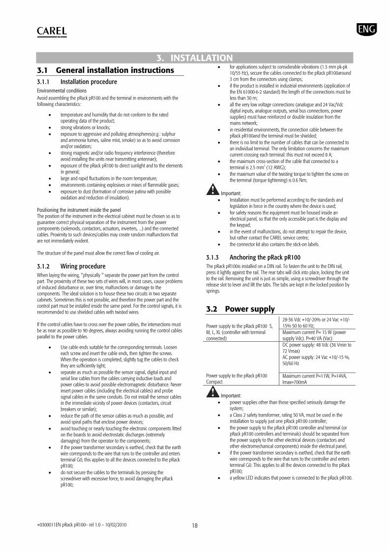
3.1.3 Anchoring the pRack pR100 The pRack pR100is installed on a DIN rail. To fasten the unit to the DIN rail, press it lightly against the rail. The rear tabs will click into place, locking the unit to the rail. Removing the unit is just as simple, using a screwdriver through the release slot to lever and lift the tabs. The tabs are kept in the locked position by springs.
3.2 Power supply 28-36 Vdc +10/-20% or 24 Vac +10/-15% 50 to 60 Hz; Power supply to the pRack pR100 S,
M, L, XL (controller with terminal connected)
Maximum current P= 15 W (power supply Vdc). P=40 VA (Vac) DC power supply: 48 Vdc (36 Vmin to 72 Vmax) AC power supply: 24 Vac +10/-15 %, 50/60 Hz
Power supply to the pRack pR100 Compact
Maximum current P=11W, P=14VA, Imax=700mA
Important: power supplies other than those specified seriously damage the
system; a Class 2 safety transformer, rating 50 VA, must be used in the
installation to supply just one pRack pR100 controller; the power supply to the pRack pR100 controller and terminal (or
pRack pR100 controllers and terminals) should be separated from the power supply to the other electrical devices (contactors and other electromechanical components) inside the electrical panel;
if the power transformer secondary is earthed, check that the earth wire corresponds to the wire that runs to the controller and enters terminal G0. This applies to all the devices connected to the pRack pR100;
a yellow LED indicates that power is connected to the pRack pR100.

+0300011EN pRack pR100– rel 1.0 – 10/02/2010 19
3.3 Connecting the analogue inputs The analogue inputs on the pRack pR100 can be configured for the most common sensors on the market: 0 to 1 V, 0 to 10 V, 0 to 20 mA, 4 to 20 mA. The different types of sensors can be selected by setting a parameter on the user terminal. 3.3.1 Connecting universal NTC temperature sensors The analogue inputs are compatible with 2-wire NTC sensors. The inputs must be set for NTC signals from the user terminal or using the default value installation procedure. The connection diagram is shown below:
Fig. 3.a
Hardware version
Terminals NTC probe cable
GND 1 Compact B1, B2, B3, B4, B5, B6, B7, B8 2 GND, BC4, BC5 1 S B1, B2, B3, B4, B5 2 GND, BC4, BC5 1 M, XL B1, B2, B3, B4, B5, B6, B7, B8 2 GND, BC4, BC5, BC9, BC10 1 L B1, B2, B3, B4, B5, B6, B7, B8, B9, B10 2
Note: the two wires of the NTC sensors are equivalent, as they have no polarity, therefore it is not necessary to follow any specific order when connecting to the terminal block.
3.3.2 Connecting PT1000 temperature sensors The pRack pR100 can be connected to 2-wire PT1000 sensors for all high temperature applications; the operating range is: -100 to 200 °C. The inputs must be pre-configured for PT1000 signals from the user terminal or using the default value installation procedure. The connection diagram is shown below:
Fig. 3.b
Hardware version
Terminals PT1000 probe cable
GND 1 Compact B3, B4 2 BC4, BC5 1 S, M, XL B4, B5 2 BC4, BC5, BC9, BC10 1 L B4, B5, B9, B10 2
Important: for correct measurements using the PT1000 sensor, each sensor wire must be connected to an individual terminal, as shown in the figure.
Note: the two wires of the PT1000 sensors are equivalent, as they have no polarity, therefore it is not necessary to follow any specific order when connecting to the terminal block.
3.3.3 Connecting current pressure probes pRack pR100 can be connected to all CAREL SPK* series active pressure probes or any other pressure sensors available on the market with 0 to 20 mA or 4 to 20 mA signal. The inputs must be set for 0 to 20 mA or 4 to 20 mA signals from the user terminal or using the default value installation procedure. The connection diagram is shown below:
Fig. 3.c
Hardware version
Terminals Probe wire colour
Description
+VDC brown power supply Compact B1, B2, B5, B6 white signal +VDC brown power supply S, M, L, XL B1, B2, B3, B6, B7, B8 white signal

+0300011EN pRack pR100– rel 1.0 – 10/02/2010 20
3.3.4 Connecting 0 to 5 V ratiometric pressure probes
pRack pR100 can be connected to any other pressure probes available on the market with 0 to 5 V ratiometric sensor. The inputs must be set for 0 to 5 V signals from the user terminal or using the default value installation procedure. The connection diagram is shown below:
Fig. 3.d
Hardware version
Terminals Probe wire colour
Description
+5Vref black power supply GND green power supply
reference
Compact
B1, B2, B5, B6 white signal +5 Vref black power supply GND green power supply
reference
S, M, L, XL
B1, B2, B3, B6, B7, B8 white signal
3.3.5 Connecting 0 to 10 V active probes PRack pR100 can be connected to 0 to 10 V sensors. The inputs must be set for 0 to 10 V signals from the user terminal or using the default value installation procedure. The connection diagram is shown below:
Fig. 3.e
Hardware version
Terminals Probe wire colour
Description
+VDC brown power supply (any)
GND - reference
Compact
B1, B2, B5, B6 - signal +VDC brown power supply
(any) S, M, L, XL
GND - reference
3.3.6 Connecting the analogue inputs selected as
ON/OFF The pRack pR100 allows some analogue inputs to be configured as voltage-free digital inputs. The inputs must be pre-configured as voltage-free digital inputs from the user terminal or using the default value installation procedure.
Fig. 3.f
Hardware version
Terminals Digital input wire
GND 1 Compact B5, B5 2 BC4, BC5 1 S, M, XL B4, B5 2 BC4, BC5, BC9, BC10 1 S, M, L, XL B4, B5, B9, B10 2
Important: the maximum current available at the digital input is 5 mA (thus the rating of the external contact must be at least 5 mA). These inputs are not optically isolated.
3.3.7 Remote connection of the analogue inputs The sizes of the cables for the remote connection of the analogue inputs are shown in the following table:
type of input size (mm2) for length up to 50 m
size (mm2) for length up to 100 m
NTC 0.5 1.0 PT1000 0.75 1.5 current 0.25 0.5 voltage 0.25 0.5
If the product is installed in industrial environments (application of the EN 61000-6-2 standard) the length of the connections must be less than 30 m. This length shouldn’t be exceeded in any case, to avoid measurement errors.
3.4 Connecting the digital inputs The pRack pR100 features digital inputs for connecting safety devices, alarms, device status and remote switches. These inputs are all optically isolated from the other terminals. They can work at 24 Vac, 24 Vdc and some at 230 Vac.
Note: separate the sensor signal and digital input cables as much as possible from the inductive load and power cables, to avoid possible electromagnetic disturbance.
Important: if the control voltage is drawn in parallel with a coil, fit a dedicated RC filter in parallel with the coil (the typical ratings are 100 , 0.5 µF, 630 V).
Important: If connecting the digital inputs to safety systems (alarms), remember that: the presence of voltage across the contact must be the normal operating condition, while no voltage must represent an alarm situation. This will ensure that any interruption (or disconnection) of the input will also be signalled. Do not connect the neutral in place of an open digital input. Always interrupt the phase. The 24 Vac/Vdc digital inputs have a resistance of around 5 k.

+0300011EN pRack pR100– rel 1.0 – 10/02/2010 21
3.4.1 Digital input connections The following figure represents one of the most common diagrams for connecting the 24 Vac and 24 Vdc digital inputs.
Fig. 3.g To maintain the optical isolation of the digital inputs, a separate power supply must be used just for the digital inputs The connection diagrams shown in these figures, which while being the more common and the more convenient, do not exclude the possibility of powering the digital inputs independently from the power supply to the pRack pR100. In any case, the inputs only have functional insulation from the rest of the controller. 3.4.2 Remote connection of the digital inputs
Important note: do not connect other devices to the IDn inputs. The sizes of the cables for the remote connection of the digital inputs are shown in the following table:
size (mm2) for length up to 50 m size (mm2) for length until 100 m 0.25 0.5
If the product is installed in industrial environments (application of the EN 61000-6-2 standard) the length of the connections must be less than 30 m. This length shouldn’t be exceeded in any case, to avoid measurement errors.
3.5 Connecting the analogue outputs 3.5.1 Connecting 0 to 10 V analogue outputs The pRack pR100 provides 0 to 10 V optically-isolated analogue outputs, powered externally at 24 Vac/Vdc. The figure below shows the electrical connection diagram; the 0V (zero) of the power supply is also the reference for the output voltage:
Fig. 3.h
Hardware version
Terminals Reference
Compact Y2 G0 S, M, XL Y1, Y2, Y3, Y4 VG0 L Y1, Y2, Y3, Y4, Y5, Y6 VG0
3.5.2 Connecting PWM analogue outputs The pRack pR100 Compact version provides a PWM analogue output (5 V pulses) for phase cutting speed controllers. The following figure shows a connection example:
Fig. 3.i
Hardware version
Terminals Reference
Compact Y1 G0 S, M, L, XL Non available
Note: the power supply to the circuit measuring the zero crossing is at terminal SYNC on the pRack pR100 Compact and must be 24 Vac, in phase with the power supply to the actuator: for three-phase power supply, use the same phase to power the pRack pR100 Compact and the actuator. 3.5.3 Optional modules Module for converting a PWM analogue output to a linear 0 to 10 V and 4 to 20 mA analogue output (code CONV0/10A0) The module is used to convert a PWM output (5 V pulses) to a linear 0 to 10 V and 4 to 20 mA analogue output (code CONV0/10A0). The control signal (at the input terminals optically-isolated from the rest of the module) must have a maximum amplitude of 5V and a period between 8 ms and 200 ms. The 0 to 10 V output voltage can be connected to a maximum load of 2 k, with a maximum ripple of 100 mV. The 4 to 20 mA current output can be connected to a maximum load of 280 , with maximum overshoot of 0.3 mA. The mechanical dimensions of the module are 87x36x60 mm (2 DIN modules) with IP20 index of protection. Module for converting a 0 to 10 V analogue output to an SPDT digital output (code CONVONOFF0) The module is used to convert a 0 to 10 V analogue output to an ON/OFF relay output. The control signal (at the input terminals, optically-isolated from the rest of the module), to ensure the switching of the relay from OFF to ON, must have a maximum amplitude of 3.3 V. The relay is SPDT, with max current of 10 A and max inductive load of 1/3 HP. The mechanical dimensions of the module are 87x36x60 mm (2 DIN modules) with IP20 index of protection.
3.6 Connecting the digital outputs 3.6.1 Electromechanical relay digital outputs The pRack pR100 features digital outputs with electromechanical relays. For ease of installation, the common terminals of some of the relays have been grouped together. If the following diagram is used, the current at the common terminals must not exceed the rating (nominal current) of a single terminal (8 A).
Fig. 3.j
The relays are divided into groups, according to the degree of insulation. Inside each group, the relays have just basic insulation and thus must have the same voltage (generally 24V ac or 110 to 230 Vac).

+0300011EN pRack pR100– rel 1.0 – 10/02/2010 22
Between the groups there is double insulation and thus the groups can have different voltages. There is also double insulation from the rest of the controller. Changeover outputs Some relays feature changeover outputs:
Hardware version Changeover relay reference
Terminal
Compact 1 J3 S 8 J15 M, XL 8, 12, 13 J15, J17, J18 L 8, 12, 13, 14, 15 J15, J17, J18, J21
3.6.2 Solid state relay (SSR) digital outputs The pRack pR100 also features a version with solid state relays (SSR) for controlling devices that require an unlimited number of switching cycles and thus would not be supported by electromechanical relays (e.g. screw compressor valves). They are dedicated to loads powered at 24 Vac/Vdc with a maximum power Pmax = 10 W.
Fig. 3.k
Hardware version SSR relay reference Terminal Compact 1, 2 J3 S 7, 8 J14, J15 M 7, 12 J14, J15 L, XL 7, 12, 14, 15 J14, J15, J21
Important: the SSR relay load is powered at 24 Vac/Vdc, thus all the other terminals in the group must be powered at 24 Vac/Vdc due to the absence of double insulation within the group. Moreover, the other terminals of the group can be powered at 110-230 Vac using a safety transformer (Class 2). 3.6.3 Summary table of digital outputs according to
the versions available Hardware version
NO contacts
NC contacts
changeover contacts
total no. of outputs
SSR relays
Compact 6 - 1 (1) 7 2 (1, 2) S 7 - 1 (8) 8 2 (7, 8) M 10 - 3 (8, 12,
13) 13 2 (7, 12)
L 13 - 5 (8, 12, 13, 14, 15)
18 4 (7, 12, 14, 15)
XL 26 - 3 (8, 12, 13)
29 4 (7, 12, 14, 15)
3.6.4 Remote connection of the digital outputs The sizes of the cables for the remote connection of the digital outputs are shown in the following table: AWG Size (mm2) Current 20 0.5 2 A 15 1.5 6 A 14 2.5 8 A If the product is installed in industrial environments (application of the EN 61000-6-2 standard) the length of the connections must be less than 30 m. This length shouldn’t be exceeded in any case, to avoid measurement errors.
3.7 pLAN electrical connections If the selected system configuration involves the connection of more than one pRack pR100 board in a pLAN, AWG20/22 twisted pair shielded cable must be used, with capacitance between the wires less than 90 PF/m. The maximum length of the pLAN network is 500 m with AWG22 twisted pair shielded cable. The boards should be connected in parallel with reference to plug-in connector J5 (pRack Compact) or J11 (versions S, M, L, XL).
Important: follow the network polarity: RX/TX+ on one board must be connected to RX/TX+ on the other boards; the same applies to RX/TX-. The figure shows the diagram for more than one board connected in a pLAN network powered by the same transformer; this is a typical application with more than one board connected inside the same electrical panel.
Fig. 3.l
Important: pLAN connections are also possible with multiple boards powered by different transformers, for further details see the pCO sistema manual, code: +030220335.

+0300011EN pRack pR100– rel 1.0 – 10/02/2010 23
4. START UP
4.1 Starting the first time After having correctly installed pRack, a number of preliminary operations are required to configure the installation.
Tutorial: pRack pR100 is ready to be configured immediately with system configurations that feature just one board and up to one terminal, by simply powering the board and connecting the terminal (if not built-in). Only for more complex configurations (e.g. more than one board in pLAN or multiple terminals) do additional operations need to be performed before switching on pRack pR100, as described in Appendix A.2. The procedure for configuring an installation described below is the same for all system configurations that feature just one pRack pR100 board, and for system configurations with more than one board connected in a pLAN. When first starting the pRack pR100 board, after waiting around 1 minute, a screen is shown for choosing the language used to display the program (English or Italian). Press ENTER () to select the language displayed.
Note: If no option is chosen within a time set by parameter and visible on the screen, the current language remains selected. After having selected the user interface language, the pRack pR100 software shows a screen for choosing between three possible system configuration solutions, as follows:
Pre-configurations Wizard
Advanced configuration
Note: after having selected a type of system configuration, it can be modified by repeating the same procedure.
4.1.1 Pre-configurations
Fig. 4.a This option is used to choose between fourteen configurations pre-loaded in the pRack pR100 software. For the description of the pre-configurations see the table below, while for the complete description of each configuration see Appendix A1.
Summary of pre-configurations
compressors fans
No.
inde
x
lines
type
No.
capa
city
steps
mod
ulat
ion
No. o
f com
p. a
larm
s
No.
inve
rter
pRac
k pR
100
vers
ion
1 RS2 1 Piston - Scroll 2 - - 1 2 - Compact
2 RS3 1 Piston - Scroll 3 - - 1 3 - Small
3 RS3p 1 Piston - Scroll 3 1 - 2 1 Inverter Medium
4 RS3i 1 Piston - Scroll 3 Inverter 3 1 Inverter Medium
5 RS4 1 Piston - Scroll 4 - - 2 4 - Medium
6 RS4i 1 Piston - Scroll 4 - Inverter 3 1 Inverter Large
7 SL3d 1 Scroll 3 - Digital 1 2 - Medium
8 SL5d 1 Scroll 5 - Digital 1 1 Inverter Medium
9 SW1 1 Screw 1 2 - 2 2 - Small
10 SW2 1 Screw 2 2 - 2 1 Inverter Small
11 SW3 1 Screw 4 2 Stepless 2 1 Inverter Medium+Small
2 - - 1 12 d-RS2 2 Piston - Scroll
2 - - 1 2 - Medium
3 - - 1 3 - 13 d-RS3 2 Piston - Scroll
3 - - 1 3 - Large
4 - Inverter 3 1 Inverter 14 d-RS4 2 Piston - Scroll
4 - Inverter 3 1 Inverter Medium + Medium

+0300011EN pRack pR100– rel 1.0 – 10/02/2010 24
4.1.2 Wizard
Fig. 4.b This is used to obtain the recommended configuration for the specific installation. By responding to a series of questions, screen by screen, the user is guided through the selection of the devices present. Once the procedure for selecting the various factors that affect the final configuration has been completed, the end result (report) is shown, and if the configuration is suitable the parameters to start operation of the pRack pR100 can be installed directly.
Note: after having configured the parameters using the Wizard, the configuration can be modified manually, within the context of the selected system configuration.
Important: before starting the pRack pR100, carefully check the settings made automatically by the software. 4.1.3 Advanced configuration
Fig. 4.c This is used to establish the configuration of the pLAN structure required for correct system operation. Once the procedure for selecting the various factors that affect the final configuration has been completed, the pRack pR100 software verifies whether
the pLAN configuration is exact and prepares the user interface for configuration of the parameters that need to be set manually by the user.
Important: this configuration solution is only recommended for expert users, as all the system parameters need to be set manually. 4.1.4 Associating the inputs and outputs When using pre-configurations and the wizard, pRack PR100 automatically associates the inputs and outputs on the board to the various functions. The association criteria used are described below. Digital outputs pRack PR100 assigns in order:
Compressor outputs: first the SSR for screw or Digital Scroll then the starting outputs, the capacity control valves and the inverter, if present
Fan outputs Global alarm
Digital inputs pRack PR100 assigns in order:
High and low pressure switches (HP and LP) Compressor alarms Fan alarms
Note: pRack PR100 can also use certain analogue inputs as digital inputs, nonetheless the common HP and LP pressure switches are always associated with actual digital inputs. Analogue inputs pRack PR100 assigns in order:
Pressure or temperature control probes for 1 or 2 lines, according to the settings made. The types of probe assigned as default are 4 to 20 mA or 0 to 5 V (first 4 to 20 mA, then 0 to 5 V if necessary) for the pressure probes, NTC for the suction temperature probes and HTNTC for the condensing temperature probes
Suction temperature probe on line 1: if possible this is associated with input B3, otherwise the first free input
Discharge temperature probe on line 1 Suction temperature probe on line 2 Discharge temperature probe on line 2
Analogue outputs pRack PR100 assigns in order:
Compressor inverters for 1 or 2 lines Fan inverters for 1 or 2 lines
+0300011EN pRack pR100– rel 1.0 – 10/02/2010 25
5. USER INTERFACE
5.1 Graphic terminal The pRack pR100 user interface is represented by the pGD1 terminal, in the wall, panel or built-in versions. The functions associated with the 6 buttons on the pGD1 terminal are described in the table below. Functions of the 6 main buttons Button Function associated
- (Alarm) displays the list of active alarms and accesses the alarm log
used to enter the main menu tree
returns to the higher level screen
- (Up) scrolls a list upwards or increases the value highlighted by the cursor
- (Down) scrolls a list downwards or decreases the value highlighted by the cursor
- (Enter) enters the selected submenu or confirms the set value. The LEDs associated with the buttons have the following meanings. Meaning of the LEDs LED Meaning
Red Flashing: active alarms present and not acknowledged Steady: alarms present and acknowledged
Yellow pRack pR100 on Green pRack pR100 powered
5.2 Description of the display There are three fundamental types of screens shown to the user:
Main screen Menu screen Screen for displaying/setting the parameters
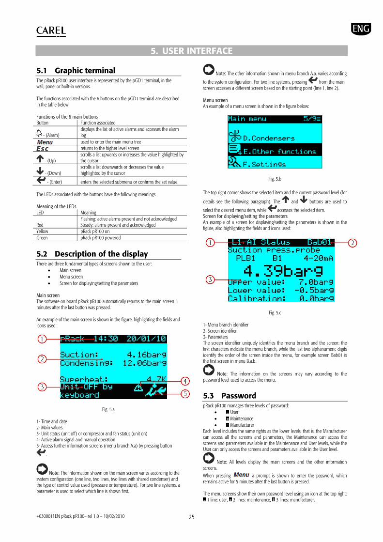
Main screen The software on board pRack pR100 automatically returns to the main screen 5 minutes after the last button was pressed. An example of the main screen is shown in the figure, highlighting the fields and icons used:
Fig. 5.a 1- Time and date 2- Main values. 3- Unit status (unit off) or compressor and fan status (unit on) 4- Active alarm signal and manual operation 5- Access further information screens (menu branch A.a) by pressing button
.
Note: The information shown on the main screen varies according to the system configuration (one line, two lines, two lines with shared condenser) and the type of control value used (pressure or temperature). For two line systems, a parameter is used to select which line is shown first.
Note: The other information shown in menu branch A.a. varies according
to the system configuration. For two line systems, pressing from the main screen accesses a different screen based on the starting point (line 1, line 2). Menu screen An example of a menu screen is shown in the figure below:
Fig. 5.b The top right corner shows the selected item and the current password level (for
details see the following paragraph). The and buttons are used to
select the desired menu item, while accesses the selected item. Screen for displaying/setting the parameters An example of a screen for displaying/setting the parameters is shown in the figure, also highlighting the fields and icons used:
Fig. 5.c 1- Menu branch identifier 2- Screen identifier 3- Parameters The screen identifier uniquely identifies the menu branch and the screen: the first characters indicate the menu branch, while the last two alphanumeric digits identify the order of the screen inside the menu, for example screen Bab01 is the first screen in menu B.a.b.
Note: The information on the screens may vary according to the password level used to access the menu.
5.3 Password pRack pR100 manages three levels of password:
User Maintenance Manufacturer
Each level includes the same rights as the lower levels, that is, the Manufacturer can access all the screens and parameters, the Maintenance can access the screens and parameters available in the Maintenance and User levels, while the User can only access the screens and parameters available in the User level.
Note: All levels display the main screens and the other information screens.
When pressing a prompt is shown to enter the password, which remains active for 5 minutes after the last button is pressed. The menu screens show their own password level using an icon at the top right:
1 line: user, 2 lines: maintenance, 3 lines: manufacturer.

+0300011EN pRack pR100– rel 1.0 – 10/02/2010 26
The password level can be changed from menu branch F.d. at any time. The password can also be changed in the corresponding menu branch.
5.4 Description of the menu Main menu – Function tree The following general rules apply to the user interface:
The parameters are grouped by functions and where necessary repeated, for example the status of the compressors inputs/outputs is visible in both branch C.a.a, and in branch B.a
The parameters are grouped by type of access, first User then Maintenance then Manufacturer
The most frequently used parameters are indicated first, the less frequently used are last
Each user only sees the parameters and menu items that are available for that access level
Only the screens and parameters corresponding to the selected system configuration are visible, that is, corresponding to the devices configured. The exception to this rule involves the screens relating to functions that can be enabled/disabled (e.g. set point compensation), which are visible even when disabled.
Regardless of the current screen displayed, pressing the Menu button accesses the main menu, as shown below:
(*)
(*)
(*)
(*)
(*)
(*)
(*)
(*)
(*)
(*)
(*)
(*)
(*)
(*)

+0300011EN pRack pR100– rel 1.0 – 10/02/2010 27
(*)
(*)
(*)
(*)
(*)
(*)
(*)
(*)
(*)
(*)
(*)
(*) this menu level is only visible for system configurations with two lines.
Note: The figure illustrates the maximum menu configuration visible with the Manufacturer password. If accessing with the User or Maintenance password, only the menu items available are visible.
Note: For some menu items, access is possible with different password levels (e.g. I/O status), but the information available on the screens changes.

+0300011IT pRack pR100– rel 1.0 – 10/02/2010 28
6. FUNCTIONS pRack PR100 can manage up to 2 suction lines and 2 condenser lines. Many of the functions described in this chapter apply in the same way to all the lines (e.g.: control, rotation), while others apply in the same way to the suction lines (e.g.: oil management). The exception involves the generic functions that apply, irrespective of line, suction or condenser, to pRack boards with pLAN addresses from 1 to 4. Where not expressly indicated or where it is clear that the description refers to one specific line rather than another (e.g.: compressor or fan management), the descriptions are considered as being common to all lines; any specific situations are described on a case-by-case basis. Below is a chart of the main functions described and their field of application:
Function L1 suction L2 suction L1 cond. L2 cond.. Unit On-Off P+I control Control in dead zone Modulation in dead zone
Cont
rol
Control with backup probes Rotation Modulation device Screw compressors - - - Reciprocating and scroll compressors - -
Com
pres
sors
Digital Scroll compressors
- -
Fan management - - Set point compensation
Ener
gy
savin
g
Floating set point
Oil management - - Subcooling - - Economizer - - Liquid injection - - Heat recovery - - Generic functions (*) ChillBooster - -
Acce
ssor
y fu
nctio
ns
DSS - - (*) not linked to lines, but rather the pLAN address of the boards The functions are described in detail in the following paragraphs.
6.1 Unit On-Off The unit can be switched on and off from:
User terminal Supervisor Digital input
On-off from the user terminal and the configuration parameters are available under the main menu, branch A.c, and are differentiated based on the access level; the User password allows display only. On-off from the supervisor and from the digital input and start-up after a blackout (with specific delay, to avoid continuous starts and stops in the event of instability in the power supply) must be enabled using the parameters visible only with the Manufacturer password. On-off from the digital input is equivalent to an enabling signal, that is, if the digital input is Off the unit cannot be switched on in any other way, while if is On, the unit can be switched on or off in any other way, with the same priority
(the most recent control has precedence, whatever the origin), as shown in the figure:
Fig. 6.1.a When there are two suction and condenser lines, on-off is independent for each line, while when there are two suction lines and one condenser line, it is independent for the suction lines, while the condenser line stops when both suction lines are off, and starts when at least one suction line is on.
Note: Certain special conditions or functions in the pRack software cause the unit to shutdown:
Configuration of some parameters: e.g. inputs/outputs, configuration of compressors, inverter parameters.
Installation of default parameters Manual management
6.2 Control pRack PR100 can manage two types of control:
Proportional band (P, P+I) Dead zone (fixed times, variable times)
Both types of control can be applied to both compressors and condensers, according to the settings defined during start-up or in main menu branches C.a.b/C.b.b and D.a.b/D.b.b. The type of control chosen is independent for each line present, either suction or condenser. In addition, pRack PR100 can use as the reference for control either the pressure or the converted temperature, or the temperature read by probe if there is no pressure probe, even if reference is only made to pressure below. The control set point can be compensated by an offset linked to digital inputs, probes, supervisor or time bands, for details see paragraph 6.5 relating to compressor and fan energy saving. Both types of control are described below, and are valid for both control of suction pressure and condensing pressure, and operation with backup probes and/or probes not working. 6.2.1 Proportional band The operating principle is normal proportional or proportional + integral control (P, P+I). The control set point is central, consequently - for proportional control only - operation is schematised in the following figure:
Digital Input
User interface
Supervisor
Unit On-Off

+0300011IT pRack pR100– rel 1.0 – 10/02/2010 29
Fig. 6.2.a For example, for 4 devices with the same capacity and proportional only control, start-up occurs as shown in the figure:
Fig. 6.2.b With P+I control, added to the effect of the proportional action described above is the integral action, used to achieve a null control error in steady operation, as shown in the figure:
Fig. 6.2.c
The integral action depends on the time and modifies the control request in proportion to the deviation from the set point. The higher is the deviation, the more intense the integral action; in addition, the lower the value of the integral time, the more intense the action. It is recommended to not set a value that is too low for the integral time, to avoid instability.
Note: the set point is in the centre of the activation band, therefore when reaching the set point some devices are on, even with purely proportional control. 6.2.2 Dead zone The operating principle is schematised in the following figure:
Fig. 6.2.d
Inside the dead zone the capacity request sent by the controller is constant (except when there is a modulation device and modulation is enabled inside the dead zone, as described in the following paragraph) and the value satisfies the temperature control request in those specific operating conditions, which means that the value of the control request changes according to how the controlled value enters the dead zone. In the decrease zone, the request also decreases at a rate that depends on the deviation from the set point, and vice-versa in the increase zone the request increases proportionally to the deviation. For the increase and decrease zones, the following can be used:
Fixed times: the request decreases or increases constantly as time elapses.
Variable times: the request decreases or increases more quickly (according to the settings) as the deviation from the set point increases.
Note: The previous figure shows the increase and decrease with fixed times. For control in dead zone, the parameters shown in the figure must be set:
Fig. 6.2.e As well as the decrease and increase differentials, 4 times need to be set, two for each zone, which represent the maximum and minimum time to reach the request, equal to 0% or 100%, for the decrease and increase respectively. In the situation shown in the figure, the request sent by the controller decreases/increases slowly as soon as the controlled value is outside of the dead zone, while it decreases/increases quickly the further the controlled value moves away from the dead zone; in this way the response of the system is faster when further from steady conditions.
P
P+I
Setpoint
time
Control variable
Diff. Diff.
Max time 0%
Decr. Diff. Control probe value
NZ timings
Decreasing zone Neutral zone Increasing zone
Setpoint
Min time 0%
Max time 100%
Min time 100%
Incr. Diff.
Diff. Diff.
100 %
Force off Control probe value
Control request
Decreasing zone Neutral zone Increasing zone
Setpoint
Differential Differential
Setpoint
Suction pressure
Devices activation
C1 C2 C3 C4
Differential Differential
100 %
Setpoint
Control probe value
Control request

+0300011IT pRack pR100– rel 1.0 – 10/02/2010 30
Note: When using fixed times, the maximum and minimum must be set to the same value. In this case, the request sent by the controller decreases/increases constantly inside the deactivation/activation differential.
TUTORIAL: the decrease/increase times (minimum and maximum) represent the time needed to change from maximum to minimum capacity and vice-versa, and not the time between the deactivation/activation of the individual device. For example, in the case of 4 devices with the same capacity, an increase time of 180 seconds means that one device is activated every 45 seconds. 6.2.3 Modulation in dead zone pRack PR100 can activate a specific function inside the dead zone if modulating devices are used (e.g.: inverters). This function can be enabled in main menu branch C.a.g/C.b.g or D.a.g/D.b.g. Modulation in dead zone is used to vary the request sent by the controller inside the dead zone proportionally so as to enter the decrease zone with the minimum request and the increase zone with the maximum request, meaning a device can be immediately deactivated/activated when exiting the dead zone. An example of this operation is shown in the figure:
Fig. 6.2.f
When entering the dead zone, the pRack PR100 software calculates how the request needs to change in order to exit the dead zone at minimum or maximum output, and applies one of the two values according to the trend in variation in the control variable. For example, at point P1 in the figure, the trend of the two requests is represented by the segments with thin lines, and the request ‘reverses’ because at that point the control variable has started increasing in value again.
Note: When exiting the dead zone, it is possible that the request is not at the minimum or maximum value, where limitation is enabled for the modulating device. 6.2.4 Control with backup probes and/or probes not working pRack PR100 can use backup control probes that are activated when the normal control probes are not working. The backup probes must be enabled in main menu branch C.a.g/C.b.g or D.a.g/D.b.g. When different pRack boards are used to manage the suction and condenser lines, the backup suction pressure probe must be connected to the board that manages the suction line, while the backup condensing pressure probe can be connected either to the board that manages the suction line or the board that manages the condenser line. If the main control probes are not working and no backup probes are fitted, or the backup probes are also not working, fixed values are used for the control request, set in main menu branch C.a.g/C.b.g or D.a.g/D.b.g.
6.3 Compressors pRack PR100 can manage up to 2 suction lines with different types of compressors and capacity modulation devices, applying common types of device rotation and controlling both the start mode and the safety times for each type of compressor, as well as a number of accessory functions. These features are described in detail in the following paragraphs. 6.3.1 Possible compressor configurations pRack PR100 can manage different types of compressors:
Reciprocating Scroll Screw
Moreover, a capacity modulation device is allowed for each suction line, which may be one of the following, according to the type of compressor: Compressors and modulation devices Compressor Modulation devices Reciprocating Inverter
Scroll Inverter Digital Scroll
Screw Inverter Continuous capacity control
Note: The same modulation device is used on each line. The maximum number of compressors and load stages per line varied according to the type of compressor: Compressors and modulation devices Compressor Maximum number Load stages Reciprocating 12 24 total Scroll 12 24 total Screw 2 4
Note: Screw compressors can only be configured on line 1. The compressors can have a maximum of 4 different capacities and a different number of load stages, but compressors of the same capacity must have the same number of load stages. The only exception is when the compressors all have the same capacity, some with load stages and some without load stages.
TUTORIAL: Below are examples of some possible configurations: One line, 4 reciprocating compressors of the same capacity, the
first with inverter One line, 4 scroll compressors of the same capacity, the first Digital
Scroll One line, 4 reciprocating compressors of the same capacity, the
first two with 4 load stages, the two other not capacity-controlled. One line, 4 reciprocating compressors of the same capacity, with 4
load stages each. Two lines, line 1 with 2 screw compressors of the same capacity,
the first with continuous modulation, line 2 with 4 reciprocating compressors in two different capacities, the first two of the same capacity T1 with 4 load stages, the two other capacity T2 with 2 load stages.
Two lines, line 1 with 4 scroll compressors, the first Digital Scroll, line 2 with 4 reciprocating compressors the first with inverter
6.3.2 Rotation pRack PR100 can manage different types of device rotation:
FIFO (First In First Out): the first device to start is also the first to stop
LIFO (Last In First Out): the last device to start is the first to stop By time: the device with the least number of operating hours starts
and the device with highest number of operating hours stops Custom: the on/off sequences are defined by the user
Note: Different sizes of compressors can only be managed with Custom rotation.
100 %
Control probe value
Control request
P1
Neutral zone

+0300011IT pRack pR100– rel 1.0 – 10/02/2010 31
The type of rotation is selected and the corresponding parameters set during the start-up procedure or in main menu branch C.a.f/C.b.f. The activation thresholds are calculated differently depending on whether FIFO, LIFO, time or Custom rotation is used: Device activation threshold calculation Rotation Threshold calculation FIFO LIFO By time
Static: the range of variation of the control request is divided equally between the number of stages available
Custom Dynamic: the thresholds are calculated depending on the capacity effectively available
Example 1: FIFO rotation, 4 compressors of the same capacity without load stages. The activation thresholds are 25, 50, 75 and 100 %.
Fig. 6.2.f
Example 2: Custom rotation, 4 compressors with capacities of 10, 20, 30 and 40 kW. The activation thresholds with all the compressors available are 10, 30, 60, 100 %.
Fig. 6.2.h
If an alarm is active on compressor 3, the recalculated activation thresholds are 10, 30, 70 %
Fig. 6.2.i
Activation of the compressors and load stages may be:
Grouped (CpppCppp): first all the load stages are activated on one compressor before starting the next one
Balanced (CCpppppp): first all the compressors are started at minimum capacity and then the corresponding load stages are activated, one for each compressor, in sequence.
6.3.3 Rotation with modulation devices pRack PR100 can also manage compressor rotation when a capacity modulation device is fitted (inverter, Digital Scroll or continuous control). The type of modulating device is selected and the corresponding parameters set during the start-up procedure or in main menu branch C.a.f/C.b.f and C.a.g/C.b.g The modulating device is always the first to start and the last to stop, the other devices start or stop according to the type of rotation selected.
Note: The compressor with modulation device is also assumed to be the first. The trend in capacity delivered by the modulation device depends on the capacity of the compressor with the modulating device compared to the other compressors available. Three cases can be identified:
compressors all with the same capacity and range of capacity variation of the modulating device greater than or equal to the capacity of the compressors
compressors all with the same capacity and range of capacity variation of the modulating device less than the capacity of the compressors
compressors with different capacities In the first case, the modulating device manages to continuously cover the range of variation of the control request, while in the second case some discontinuous variations remain. The behaviour in the third case varies according to the capacities involved, and in any case reflects one of the two previous cases. To configure the compressor capacity when an inverter is used, the minimum and maximum operating frequencies need to be set relating to the minimum and maximum value of the analogue output and the rated capacity delivered at rate frequency, so that the pRack PR100 software can calculate the capacity the compressor can deliver with the inverter and use this value for control. In addition, for inverters the variation in capacity delivered can be limited by setting the increase and decrease times. If these times have already been configured on the inverter, the higher time set has priority.
Example 1: two compressors without capacity control, with the same capacity, 20 kW each, modulating device with variable capacity between 30 and 60 kW. The figure shows the trend when the request sent by the controller increases and then decreases continuously between 0 and 100 %.
Fig. 6.3.a
Example 2: two compressors without capacity control, with the same capacity, 30 kW each, modulating device with variable capacity between 20 and 40 kW.
Control request
Actual capacity [kW]
100
20
80
60
40
Step compressors capacity
Inverter capacity Total capacity
10% 30% 70%
C2 C4
Control request
10% 30% 60% 100% Control request
C1 C2 C3 C4
25% 50% 75% 100% Control request
C1 C2 C3 C4
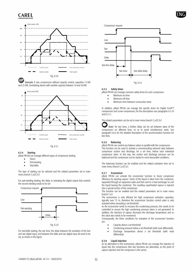
+0300011IT pRack pR100– rel 1.0 – 10/02/2010 32
Fig. 6.3.b
Example 3: two compressors without capacity control, capacities 15 kW and 25 kW, modulating device with variable capacity between 10 and 30 kW.
Fig. 6.3.c 6.3.4 Starting pRack PR100 can manage different types of compressor starting:
Direct Part-winding Star/delta
The type of starting can be selected and the related parameters set in main menu branch C.a.f/C.b.f. For part-winding starting, the delay in activating the digital output that controls the second winding needs to be set:
Fig. 6.3.d For star/delta starting, the star time, the delay between the activation of the line and star digital input, and between the delta and star digital input all need to be set, as shown in the figure:
Fig. 6.3.e 6.3.5 Safety times pRack PR100 can manage common safety times for each compressor:
Minimum on time Minimum off time Minimum time between consecutive starts
In addition, pRack PR100 can manage the specific times for Digital Scroll compressors and screw compressors; for the descriptions see paragraphs 6.3.10 and 6.3.11. The related parameters can be set in main menu branch C.a.f/C.b.f.
Note: for two lines, a further delay can be set between starts of the compressors on different lines, so as to avoid simultaneous starts. See paragraph 6.6.6 for the detailed description of the synchronisation function for two lines. 6.3.6 Balancing pRack PR100 can control any balance valves in parallel with the compressors. This function can be used to activate a communicating solenoid valve between compressor suction and discharge, for a set time, before each individual compressor starts. In this way, the suction and discharge pressure can be balanced and the compressor can be started in more favourable conditions. The balancing function can be enabled and the related activation time set in main menu branch C.a.f/C.b.f. 6.3.7 Economizer pRack PR100 can activate the economizer function to boost compressor efficiency by injecting vapour. Some of the liquid is taken from the condenser, expanded through an expansion valve and then sent to a heat exchanger to cool the liquid leaving the condenser. The resulting superheated vapour is injected into a special section of the compressor. The function can be enabled and the related parameters set in main menu branch C.a.f. The economizer is only efficient for high compressor activation capacities, typically over 75 %, therefore the economizer function control valve is only activated when exceeding a set threshold. As the economizer tends to increase the condensing pressure, this needs to be controlled to ensure the high condensing pressure alarm is not generated. In addition, the injection of vapour decreases the discharge temperature and so this value also needs to be monitored. Consequently, the three conditions for activation of the economizer function are:
Capacity above a set threshold Condensing pressure below a set threshold (with reset differential) Discharge temperature above a set threshold (with reset
differential) 6.3.8 Liquid injection As an alternative to the economizer, pRack PR100 can manage the injection of liquid into the compressors (the two functions are alternative, as the point of vapour injection into the compressor is the same).
Control request
Actual capacity [kW]
70
10
50
30
Step compressors capacity
Inverter capacity Total capacity
Control request
Actual capacity [kW]
100
20
80
60
40
Step compressors capacity
Inverter capacity Total capacity
Line
Star
Compressor request
Star time
Delta
Star-line delay
Star-delta delay
Line
Part-winding
Compressor request
Delay
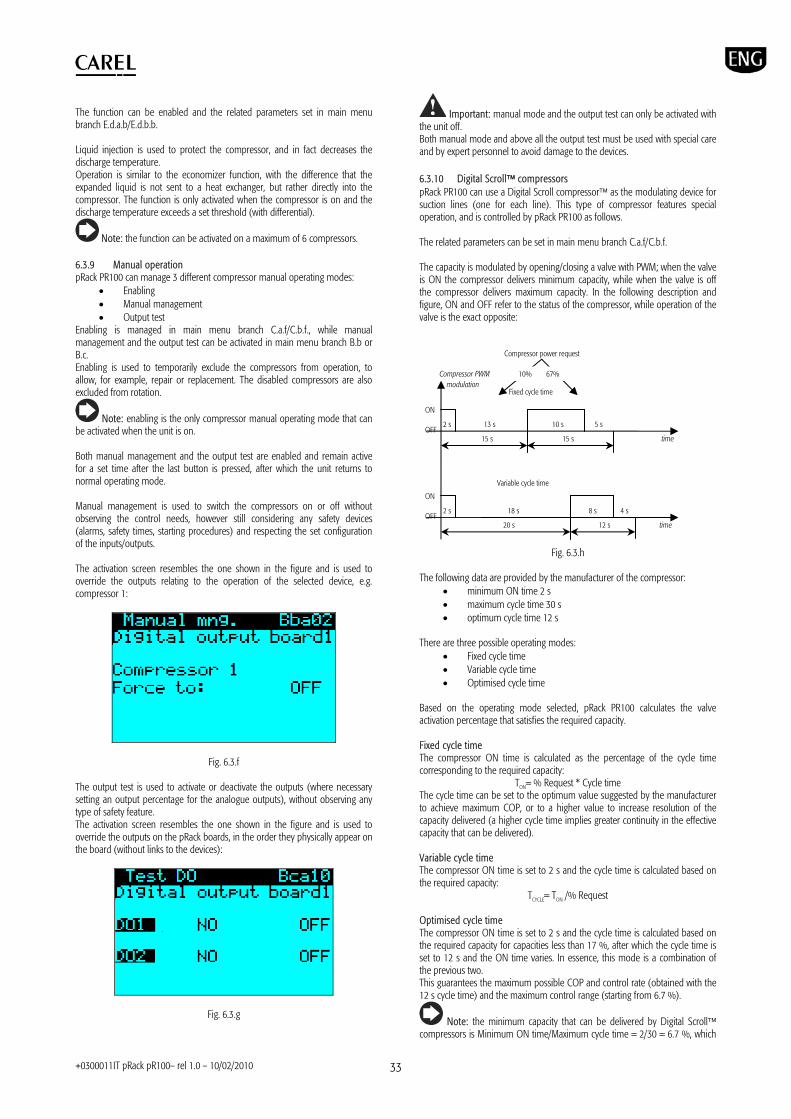
+0300011IT pRack pR100– rel 1.0 – 10/02/2010 33
The function can be enabled and the related parameters set in main menu branch E.d.a.b/E.d.b.b. Liquid injection is used to protect the compressor, and in fact decreases the discharge temperature. Operation is similar to the economizer function, with the difference that the expanded liquid is not sent to a heat exchanger, but rather directly into the compressor. The function is only activated when the compressor is on and the discharge temperature exceeds a set threshold (with differential).
Note: the function can be activated on a maximum of 6 compressors. 6.3.9 Manual operation pRack PR100 can manage 3 different compressor manual operating modes:
Enabling Manual management Output test
Enabling is managed in main menu branch C.a.f/C.b.f., while manual management and the output test can be activated in main menu branch B.b or B.c. Enabling is used to temporarily exclude the compressors from operation, to allow, for example, repair or replacement. The disabled compressors are also excluded from rotation.
Note: enabling is the only compressor manual operating mode that can be activated when the unit is on. Both manual management and the output test are enabled and remain active for a set time after the last button is pressed, after which the unit returns to normal operating mode. Manual management is used to switch the compressors on or off without observing the control needs, however still considering any safety devices (alarms, safety times, starting procedures) and respecting the set configuration of the inputs/outputs. The activation screen resembles the one shown in the figure and is used to override the outputs relating to the operation of the selected device, e.g. compressor 1:
Fig. 6.3.f The output test is used to activate or deactivate the outputs (where necessary setting an output percentage for the analogue outputs), without observing any type of safety feature. The activation screen resembles the one shown in the figure and is used to override the outputs on the pRack boards, in the order they physically appear on the board (without links to the devices):
Fig. 6.3.g
Important: manual mode and the output test can only be activated with the unit off. Both manual mode and above all the output test must be used with special care and by expert personnel to avoid damage to the devices. 6.3.10 Digital Scroll compressors pRack PR100 can use a Digital Scroll compressor as the modulating device for suction lines (one for each line). This type of compressor features special operation, and is controlled by pRack PR100 as follows. The related parameters can be set in main menu branch C.a.f/C.b.f. The capacity is modulated by opening/closing a valve with PWM; when the valve is ON the compressor delivers minimum capacity, while when the valve is off the compressor delivers maximum capacity. In the following description and figure, ON and OFF refer to the status of the compressor, while operation of the valve is the exact opposite:
Fig. 6.3.h
The following data are provided by the manufacturer of the compressor:
minimum ON time 2 s maximum cycle time 30 s optimum cycle time 12 s
There are three possible operating modes:
Fixed cycle time Variable cycle time Optimised cycle time
Based on the operating mode selected, pRack PR100 calculates the valve activation percentage that satisfies the required capacity. Fixed cycle time The compressor ON time is calculated as the percentage of the cycle time corresponding to the required capacity:
TON= % Request * Cycle time The cycle time can be set to the optimum value suggested by the manufacturer to achieve maximum COP, or to a higher value to increase resolution of the capacity delivered (a higher cycle time implies greater continuity in the effective capacity that can be delivered). Variable cycle time The compressor ON time is set to 2 s and the cycle time is calculated based on the required capacity:
TCYCLE= TON /% Request Optimised cycle time The compressor ON time is set to 2 s and the cycle time is calculated based on the required capacity for capacities less than 17 %, after which the cycle time is set to 12 s and the ON time varies. In essence, this mode is a combination of the previous two. This guarantees the maximum possible COP and control rate (obtained with the 12 s cycle time) and the maximum control range (starting from 6.7 %).
Note: the minimum capacity that can be delivered by Digital Scroll compressors is Minimum ON time/Maximum cycle time = 2/30 = 6.7 %, which
Fixed cycle time
15 s 15 s time
2 s 13 s 10 s 5 s
Variable cycle time
2 s 18 s 8 s 4 s
20 s 12 s time
ON OFF
ON OFF
10% 67%Compressor PWM modulation
Compressor power request

+0300011IT pRack pR100– rel 1.0 – 10/02/2010 34
also depends on the selected control mode (for example, in the first case shown in the figure the minimum capacity delivered is Minimum ON time/Cycle time = 2/15 = 13%).
Note: if high pressure prevention is enabled with activation/deactivation of the devices, the Digital Scroll compressor delivers the minimum possible capacity. Starting procedure pRack PR100 can manage the specific starting procedure for Digital Scroll compressors, as represented as in the following figure:
Fig. 6.3.i
There are three stages:
1. balance: the PWM valve is activated for 4 s, so that the compressor delivers minimum capacity
2. compressor activation with 50 % capacity for 3 minutes 3. forced operation at 100 % for 1 minute
During the starting procedure, the request sent by the controller is ignored and only at the end of the procedure does the capacity delivered start reflecting the request. If the request is cancelled during the starting procedure, the compressor stops at the end, then the minimum ON time for these types of compressors is set to 244 s.
Note: the safety times for Digital Scroll compressors are established by the manufacturer, and are as follows:
Minimum ON time: 244 s (starting procedure) Minimum OFF time: 180 s Minimum time between restarts: 360 s
Alarms pRack PR100 can manage, in addition to the common alarms for all types of compressors (see chapter 8 for details), some specific alarms for Digital Scroll compressors:
high oil temperature oil dilution high discharge temperature
These alarms are managed as specified by the manufacturer of the compressor, and therefore pRack PR100 can only enable or disable them. Activation of these alarms requires an oil temperature probe, which can also be the common probe (see the paragraph relating to oil management) and the compressor discharge temperature probe.
Note: pRack PR100 does not manages the envelope for Digital Scroll compressors and consequently there is no corresponding alarm when operating outside the envelope. 6.3.11 Screw compressors pRack PR100 can manage up to two screw compressors, with control in stages or continuous control (only the first compressor with continuous control, used as modulation device for the suction line), which can be a generic device or pre-configured in accordance with the most common devices supplied by the main manufacturers. Advanced functions are also available, for example envelope control, described further on. The parameters relating to screw compressors can be set in main menu branch C.a.f/C.b.f.
Screw compressors are fitted with up to 4 capacity control valves (hereinafter V1, V2, V3, V4), which can have 4 types of behaviour:
ON: the valve is open
OFF: the valve is closed Intermittent: the valve is open/closed alternatively (around 10
to 15 s) Pulsating: the valve is open/closed alternatively with very short
opening/closing times (around 1 to 2 s)
Important: pulsating valves must be associated with an SSR relay output, to avoid damage. V1, V2, V3 and V4 can be managed to obtain stage or continuous compressor control. Stage control For the control in stages, normally involving four load stages, 25, 50, 75, 100 %, a table needs to be created that shows the behaviour of each valve in the different conditions (starting, 25 %, 50 %, 75 %, 100 %). The figure shows one possible example (see the documents supplied by the manufacturer of the compressor for how to complete the table):
V1 V2 V3 V4 Start 25% 50% 75% 100%
If intermittent valves are used, the cycle time also needs to be set.
Note: normally operation at minimum capacity (25 %) is only possible for a limited time, after which the compressor must switch to the next stage. This function can be enabled and the corresponding time can be set. Continuous control For continuous control, a table needs to be created that shows the behaviour of each valve in the different conditions (start/stop, increase, decrease, standby). The figure shows one possible example:
V1 V2 Start/Stop Increase (25 to 100%) Decrease (25 to 100%) Standby
If intermittent/pulsating valves are used, the cycle time also needs to be set. Intermittent valves are opened/closed for 50 % of the set time, while for pulsating valves the opening and closing time in theory depend on the difference between the position of the slide and the capacity request. As the position of the slide is generally not measurable, the variation in the request is used to calculate the times for pulsating valves.
Note: in continuous control, operation is normally only allowed for an undetermined time when the capacity exceeds 50 %. Starting procedure pRack PR100 can manage the starting procedure for the screw compressors by considering, following the star/delta or part-winding starting selected, a further time of operation at minimum capacity, established by the manufacturer or set to 60 s for generic compressors. Once the starting procedure has ended, the compressor starts varying the capacity according to the control request and if necessary considering the duration at minimum capacity. Series of compressors supported pRack PR100 can manage several series of screw compressors made by the main manufacturers, (Bitzer, Refcomp, Hanbell, …) which come with the parameters described above already set. For manufacturers or series of compressors that are not supported, the generic type can be used and the corresponding parameters set as described previously.
4s 180s 60s
50% 100%
Startup
Request
Valve
Comp.
Time

+0300011IT pRack pR100– rel 1.0 – 10/02/2010 35
Note: for further details on the series of compressors supported and the related pre-configured parameters, contact Carel. Envelope For screw compressors, pRack PR100 can manage control of the envelope, which can either be pre-set or defined by the user. pRack PR100 accepts the envelope control settings for the Bitzer CSH series compressors, and these simply need to be enabled in main menu branch C.a.g. For all other series of compressors, the envelope can be managed by enabling and setting all the related parameters in main menu branch C.a.g. The following parameters need to be set in order to manage the envelope:
Definition of the points (maximum 30) Definition of the zone (maximum 12). Each zone can be made up
of one or more polygons (total maximum 14, which must be closed and convex)
Definition of the behaviour of the compressor in the different zones (capacity and duration)
The meaning of the parameters is shown in the figure:
Fig. 6.3.j
pRack PR100 can also manage the variation in the envelope as the capacity delivered changes, for example in the case of variation in frequency for inverter-driven compressors.
Note: for further details on configuration of the envelope, contact Carel.
6.4 Fans pRack PR100 can manage up to 2 condenser lines with up to 16 fans and one speed modulation device each, applying common types of device rotation and controlling both the starting mode and some accessory functions. The modulation device may be an inverter or a phase fired controller. The functions are described in detail below. 6.4.1 Control pRack PR100 can manage – as described in paragraph 6.2 – proportional band and dead zone control, by pressure or temperature. For details on the control modes, see the corresponding paragraph, while below is the description only of the features relating to the fans. Fan operation depending on the compressors The operation of the fans can be bound to the operation of the compressors by setting a parameter in main menu branch D.a.b/D.b.b, in this case the fans only start if at least one compressor is on. This setting is ignored if the fans are controlled by a dedicated pRack PR100 board and the pLAN network is disconnected. Cut-off pRack PR100 can manage a control cut-off for the fans, as shown in the figure:
Fig. 6.3.k
The function can be enabled and the related parameters set in main menu branch D.a.b/D.b.b For the cut-off a percentage value, a set point, a differential and hysteresis can be set. 6.4.2 Rotation pRack PR100 can manage rotation of the fans, much in the same way as described for the compressors, therefore:
LIFO, FIFO, time, Custom rotation Management of a modulation device on each line
The substantial difference compared to the compressors concerns the possibility to manage different capacities and load stages, which are obviously not featured for the fans. In addition, pRack PR100 can specially manage inverter driven fans. In fact, a multiple number of inverter driven fans can be set. If there is more than one fan, however the number of inverter driven fans is set to 1, the fans are started and stopped at the same time, and the fans will always all be at the same power. If there is more than one inverter driven fan, as well as being able to use an alarm digital input for each, it is assumed that the weight of the modulating device is proportional to the number of fans, therefore the first case is applied, as described in paragraph 6.3.3.
Example 1: six fans, three of which inverter driven fans, correspond to four fans in which the first has triple the power of the others.
Note: some fans can be excluded from the rotation, for example in the winter; to do this use the split condenser function described in paragraph 6.4.5. 6.4.3 Fast start (speed up) pRack PR100 can manage the fast start function (speed up), used to overcome the initial inertia of the fans. The function can be enabled and the related parameters set in main menu branch D.a.g/D.b.g If speed up is enabled, a start time can be set in which the fan speed is forced to 100%. If the outside temperature sensor is used, moreover, a threshold can be set (with reset differential) below which speed up is disabled, so as to not drastically lower the condensing pressure at start-up.
Note: speed up has lower priority than the silencer function (see the following paragraph for the details), therefore if the silencer function is active, this is disabled. 6.4.4 Silencer pRack PR100 can manage the silencer function, used to limit fan speed at certain times of the day or in specific conditions, enabled by digital input. The function can be enabled and the related parameters set in main menu branch D.a.g/D.b.g. Enabling fan speed limitation from the digital input or based on time bands is independent, consequently the speed is limited to the set value when at least one of the two conditions is active.
Differential
MAX
Control probe value
Control request
Cut-off value
Hyst. Setpoint
Zone 1 (Pol. 1)
Discharge pressure
Suction pressure
P1
(Pol. 2)
(Pol. 3)
Zone 2
P2 P3
P4
P5
P6 P7 P8

+0300011IT pRack pR100– rel 1.0 – 10/02/2010 36
Up to 4 activation bands can be set for each day of the week. 6.4.5 Split condenser pRack PR100 can manage the possibility to exclude some fans from operation, for example to reduce condenser operation in winter, using the split condenser function. The function can be enabled and the related parameters set in main menu branch D.a.g/D.b.g. Split condenser can be used to exclude from rotation fans whose index is:
even odd higher than a settable value lower than a settable value
The function can be activated by:
time bands (winter/summer seasons) digital input supervisor outside temperature (set threshold and differential)
Note: the split condenser function can be disabled by parameter if the high pressure prevention function is activated (see paragraph 8.3.3). If split condenser is disabled due to activation of the high pressure prevention function, it remains disabled for a set time, after which it is reactivated.
Note: split condenser cannot be enabled if there is a speed modulation device that controls all the fans. 6.4.6 Manual operation pRack PR100 can also manage the same three manual operating modes for the fans as described for the compressors:
Enabling Manual management Output test
Enabling is managed in main menu branch D.a.f/D.b.f., while manual management and the output test can be activated in main menu branch B.b or B.c. For the detailed description of the three modes, see paragraph 6.3.9. 6.4.7 Alarms pRack PR100 can manage both a common alarm for the fans and separate alarms for each fan. When the common alarm is active the alarm is signalled, but no fan is stopped, while for separate alarms the fan that the alarm refers to is stopped. For details on the fan alarms, see Chapter 8.
6.5 Energy saving pRack PR100 can activate energy saving functions by adjusting the suction and condensing pressure set points. The suction and condensing pressure set points can be applied with two different offsets, one for the closing period and one for the winter period, activated by:
Digital input Time band Supervisor
As well as set point compensation, two further energy saving functions are available, and involve floating suction and condensing pressure set point. While compensation is similar for the suction and condensing pressure, floating set point works differently (see the description in the following paragraphs). The effects of compensation and floating set points are independent. The functions can be enabled and the related parameters set in main menu branch C.a.d/C.b.d and D.a.d/D.b.d.
6.5.1 Set point compensation The following description applies to both the suction and condensing pressure set points. Two different offsets can be defined, which apply to:
Closing periods, defined by the scheduler, activation of a digital input or supervisor
Winter period, defined by the scheduler The two offsets add to the set point defined by the user when the corresponding condition is active.
Example 1: closing offset 0.3 barg, winter offset 0.2 barg, suction pressure compensation from scheduler and from digital input activated. When the digital input is activated, for example with a day/night function, 0.3 barg is added to the operating set point, and when the winter period is in progress a further 0.2 barg is added. The operation can be schematised in the following figure:
Fig. 6.5.a
Note: the same digital input is used for set point compensation on each line, so if suction and condensing pressure set point compensation is activated by digital input, both compensation functions are active at the same time. 6.5.2 Floating suction pressure set point For the suction line, the floating set point is managed by the supervisor. The suction pressure set point set by the user is changed by the supervisor in range between a settable minimum and maximum. The operation is illustrated in the following figure:
Fig. 6.5.b
The set point is calculated by the supervisor and acquired by the pRack PR100 controller at set intervals, the maximum variation allowed for the set point in each sampling period can also be set; if the value acquired differs from the previous value by more than the maximum variation allowed, the variation is limited to the maximum value. If the supervisor is disconnected, after 10 minutes (fixed) the pRack PR100 controller starts decreasing the set point with variations equal to the maximum variation allowed each sampling period, until reaching the minimum set point allowed with floating condensing pressure.
Note: if set point compensation is also active, the floating set point is the value that the variation is applied to, that is, the two effects are summed.
Max variation
Floating setpointMax
Min
Sampling time time
Real variation
Digital Input e.g.:day/night
Cool/Heat
Setpoint user setpoint +0,5 barg
time
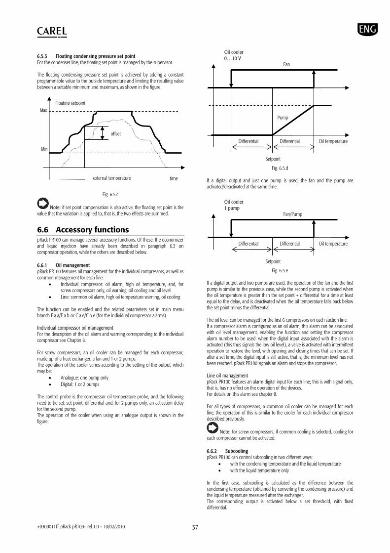
+0300011IT pRack pR100– rel 1.0 – 10/02/2010 37
6.5.3 Floating condensing pressure set point For the condenser line, the floating set point is managed by the supervisor. The floating condensing pressure set point is achieved by adding a constant programmable value to the outside temperature and limiting the resulting value between a settable minimum and maximum, as shown in the figure:
Fig. 6.5.c
Note: if set point compensation is also active, the floating set point is the value that the variation is applied to, that is, the two effects are summed.
6.6 Accessory functions pRack PR100 can manage several accessory functions. Of these, the economizer and liquid injection have already been described in paragraph 6.3 on compressor operation, while the others are described below. 6.6.1 Oil management pRack PR100 features oil management for the individual compressors, as well as common management for each line:
Individual compressor: oil alarm, high oil temperature, and, for screw compressors only, oil warning, oil cooling and oil level
Line: common oil alarm, high oil temperature warning, oil cooling The function can be enabled and the related parameters set in main menu branch E.a.a/E.a.b or C.a.e/C.b.e (for the individual compressor alarms). Individual compressor oil management For the description of the oil alarm and warning corresponding to the individual compressor see Chapter 8. For screw compressors, an oil cooler can be managed for each compressor, made up of a heat exchanger, a fan and 1 or 2 pumps. The operation of the cooler varies according to the setting of the output, which may be:
Analogue: one pump only Digital: 1 or 2 pumps
The control probe is the compressor oil temperature probe, and the following need to be set: set point, differential and, for 2 pumps only, an activation delay for the second pump. The operation of the cooler when using an analogue output is shown in the figure:
Fig. 6.5.d
If a digital output and just one pump is used, the fan and the pump are activated/deactivated at the same time:
Fig. 6.5.e
If a digital output and two pumps are used, the operation of the fan and the first pump is similar to the previous case, while the second pump is activated when the oil temperature is greater than the set point + differential for a time at least equal to the delay, and is deactivated when the oil temperature falls back below the set point minus the differential. The oil level can be managed for the first 6 compressors on each suction line. If a compressor alarm is configured as an oil alarm, this alarm can be associated with oil level management, enabling the function and setting the compressor alarm number to be used: when the digital input associated with the alarm is activated (this thus signals the low oil level), a valve is activated with intermittent operation to restore the level, with opening and closing times that can be set. If after a set time, the digital input is still active, that is, the minimum level has not been reached, pRack PR100 signals an alarm and stops the compressor. Line oil management pRack PR100 features an alarm digital input for each line; this is with signal only, that is, has no effect on the operation of the devices. For details on this alarm see chapter 8. For all types of compressors, a common oil cooler can be managed for each line; the operation of this is similar to the cooler for each individual compressor described previously.
Note: for screw compressors, if common cooling is selected, cooling for each compressor cannot be activated. 6.6.2 Subcooling pRack PR100 can control subcooling in two different ways:
with the condensing temperature and the liquid temperature with the liquid temperature only
In the first case, subcooling is calculated as the difference between the condensing temperature (obtained by converting the condensing pressure) and the liquid temperature measured after the exchanger. The corresponding output is activated below a set threshold, with fixed differential.
Differential Differential
Setpoint
Oil temperature
Fan/Pump
Oil cooler 1 pump
Differential Differential
Pump
Setpoint
Oil temperature
Fan
Oil cooler 0…10 V
offset
Floating setpoint Max
Min
time external temperature
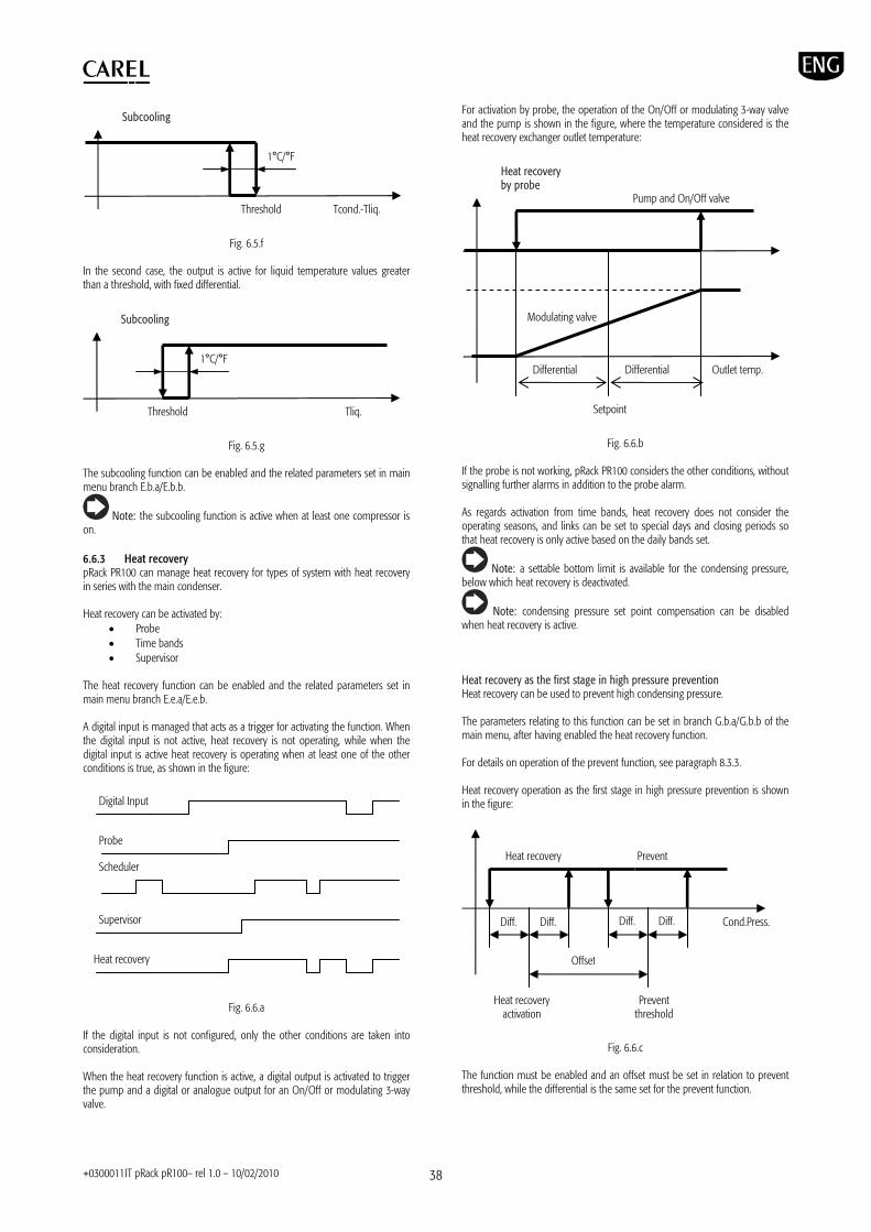
+0300011IT pRack pR100– rel 1.0 – 10/02/2010 38
Fig. 6.5.f In the second case, the output is active for liquid temperature values greater than a threshold, with fixed differential.
Fig. 6.5.g The subcooling function can be enabled and the related parameters set in main menu branch E.b.a/E.b.b.
Note: the subcooling function is active when at least one compressor is on. 6.6.3 Heat recovery pRack PR100 can manage heat recovery for types of system with heat recovery in series with the main condenser. Heat recovery can be activated by:
Probe Time bands Supervisor
The heat recovery function can be enabled and the related parameters set in main menu branch E.e.a/E.e.b. A digital input is managed that acts as a trigger for activating the function. When the digital input is not active, heat recovery is not operating, while when the digital input is active heat recovery is operating when at least one of the other conditions is true, as shown in the figure:
Fig. 6.6.a
If the digital input is not configured, only the other conditions are taken into consideration. When the heat recovery function is active, a digital output is activated to trigger the pump and a digital or analogue output for an On/Off or modulating 3-way valve.
For activation by probe, the operation of the On/Off or modulating 3-way valve and the pump is shown in the figure, where the temperature considered is the heat recovery exchanger outlet temperature:
Fig. 6.6.b If the probe is not working, pRack PR100 considers the other conditions, without signalling further alarms in addition to the probe alarm. As regards activation from time bands, heat recovery does not consider the operating seasons, and links can be set to special days and closing periods so that heat recovery is only active based on the daily bands set.
Note: a settable bottom limit is available for the condensing pressure, below which heat recovery is deactivated.
Note: condensing pressure set point compensation can be disabled when heat recovery is active. Heat recovery as the first stage in high pressure prevention Heat recovery can be used to prevent high condensing pressure. The parameters relating to this function can be set in branch G.b.a/G.b.b of the main menu, after having enabled the heat recovery function. For details on operation of the prevent function, see paragraph 8.3.3. Heat recovery operation as the first stage in high pressure prevention is shown in the figure:
Fig. 6.6.c The function must be enabled and an offset must be set in relation to prevent threshold, while the differential is the same set for the prevent function.
Differential Differential
Modulating valve
Setpoint
Outlet temp.
Pump and On/Off valve
Heat recovery by probe
Digital Input
Probe
Scheduler
Supervisor
Heat recovery
1°C/°F
Tliq.
Subcooling
Threshold
1°C/°F
Tcond.-Tliq.
Subcooling
Threshold
Prevent threshold
Diff.
Heat recovery activation
Diff. Diff.
Offset
Diff. Cond.Press.
Heat recovery Prevent

+0300011IT pRack pR100– rel 1.0 – 10/02/2010 39
6.6.4 Generic functions pRack PR100 can use the free inputs /outputs and certain internal variables for generic functions.
Important: The generic functions are available on pRack PR100 boards with pLAN addresses from 1 to 4, that is, on all boards that manage a suction or condensing line, nonetheless only the parameters corresponding to the functions managed by boards 1 and 2 are sent to the supervisory system. The following generic functions are available for each board:
5 stages 2 modulations 2 alarms 1 scheduler
Each function can be enabled/disabled by digital input and from the user interface. The generic functions can be enabled and the related parameters set in main menu branch E.f. To be able to use the free inputs, these must be configured as generic probes from A to E (analogue inputs) and generic inputs from F to J (digital inputs), consequently a maximum of 5 analogue and 5 digital inputs can be used. After having configured the generic probes, the associated variables can be used as control variables and the digital inputs as enabling variables. As well as the generic probes and inputs, pRack PR100 software internal variables can be used, depending on the system configuration. Some examples are, for analogue variables:
Suction pressure Condensing pressure Saturated suction temperature Saturated condensing temperature % of compressors active % of fans active Superheat
And for the digital variables: High suction pressure alarm Low suction pressure alarm High condensing pressure alarm Low suction pressure alarm Sign of life
Each generic function can be associated with a unit of measure and a description. Below is a description of the operation of four types of generic functions. Stages pRack PR100 can manage up to 5 stage functions, with either direct or reverse operation. In both cases, a set point and a differential can be set; the operation of the corresponding output is shown in the figure for both cases:
Fig. 6.6.d If an enabling variable has been set, the corresponding output is active if the enabling is also active. For each stage, a high alarm threshold and a low alarm threshold can be set, and are absolute. For each alarm, the activation delay and priority can be set. See chapter 8 for details on the alarms. One example of using the generic stage functions may be activation of the fans on the room units based on the temperature. Modulation pRack PR100 can manage up to 2 modulation functions, with either direct or reverse operation. In both cases, a set point and a differential can be set; the operation of the corresponding output is shown in the figure for direct mode, with the cut-off function also enabled:
Fig. 6.6.e
If an enabling variable has been set, the corresponding output is active if the enabling is also active. For each modulation, a high alarm threshold and a low alarm threshold can be set, and are absolute. For each alarm, the activation delay and priority can be set. See chapter 8 for details on the alarms. For modulation a minimum and maximum value can also be set for the output, and the cut-off function can be enabled, with operation as shown in the previous figure. Alarms pRack PR100 can manage up to 2 alarm functions, with settable digital variable to be monitored, activation delay, priority and description. One example of using the generic alarm functions involves detecting gas leaks.
Hysteresis Differential
MAX
Control variable
Direct modulation
MIN (Cut-off Value)
Setpoint
Control variable
Direct stage
Setpoint
Diff. Diff.
Reverse stage
Setpoint
Diff. Diff. Control variable
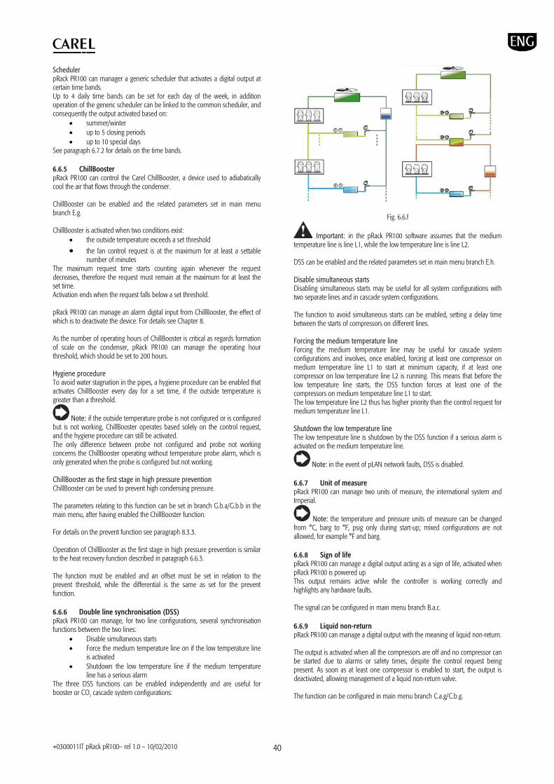
+0300011IT pRack pR100– rel 1.0 – 10/02/2010 40
Scheduler pRack PR100 can manager a generic scheduler that activates a digital output at certain time bands. Up to 4 daily time bands can be set for each day of the week, in addition operation of the generic scheduler can be linked to the common scheduler, and consequently the output activated based on:
summer/winter up to 5 closing periods up to 10 special days
See paragraph 6.7.2 for details on the time bands. 6.6.5 ChillBooster pRack PR100 can control the Carel ChillBooster, a device used to adiabatically cool the air that flows through the condenser. ChillBooster can be enabled and the related parameters set in main menu branch E.g. ChillBooster is activated when two conditions exist:
the outside temperature exceeds a set threshold
the fan control request is at the maximum for at least a settable number of minutes
The maximum request time starts counting again whenever the request decreases, therefore the request must remain at the maximum for at least the set time. Activation ends when the request falls below a set threshold. pRack PR100 can manage an alarm digital input from ChillBooster, the effect of which is to deactivate the device. For details see Chapter 8. As the number of operating hours of ChillBooster is critical as regards formation of scale on the condenser, pRack PR100 can manage the operating hour threshold, which should be set to 200 hours. Hygiene procedure To avoid water stagnation in the pipes, a hygiene procedure can be enabled that activates ChillBooster every day for a set time, if the outside temperature is greater than a threshold.
Note: if the outside temperature probe is not configured or is configured but is not working, ChillBooster operates based solely on the control request, and the hygiene procedure can still be activated. The only difference between probe not configured and probe not working concerns the ChillBooster operating without temperature probe alarm, which is only generated when the probe is configured but not working. ChillBooster as the first stage in high pressure prevention ChillBooster can be used to prevent high condensing pressure. The parameters relating to this function can be set in branch G.b.a/G.b.b in the main menu, after having enabled the ChillBooster function. For details on the prevent function see paragraph 8.3.3. Operation of ChillBooster as the first stage in high pressure prevention is similar to the heat recovery function described in paragraph 6.6.3. The function must be enabled and an offset must be set in relation to the prevent threshold, while the differential is the same as set for the prevent function. 6.6.6 Double line synchronisation (DSS) pRack PR100 can manage, for two line configurations, several synchronisation functions between the two lines:
Disable simultaneous starts Force the medium temperature line on if the low temperature line
is activated Shutdown the low temperature line if the medium temperature
line has a serious alarm The three DSS functions can be enabled independently and are useful for booster or CO2 cascade system configurations:
Fig. 6.6.f
Important: in the pRack PR100 software assumes that the medium temperature line is line L1, while the low temperature line is line L2. DSS can be enabled and the related parameters set in main menu branch E.h. Disable simultaneous starts Disabling simultaneous starts may be useful for all system configurations with two separate lines and in cascade system configurations. The function to avoid simultaneous starts can be enabled, setting a delay time between the starts of compressors on different lines. Forcing the medium temperature line Forcing the medium temperature line may be useful for cascade system configurations and involves, once enabled, forcing at least one compressor on medium temperature line L1 to start at minimum capacity, if at least one compressor on low temperature line L2 is running. This means that before the low temperature line starts, the DSS function forces at least one of the compressors on medium temperature line L1 to start. The low temperature line L2 thus has higher priority than the control request for medium temperature line L1. Shutdown the low temperature line The low temperature line is shutdown by the DSS function if a serious alarm is activated on the medium temperature line.
Note: in the event of pLAN network faults, DSS is disabled. 6.6.7 Unit of measure pRack PR100 can manage two units of measure, the international system and Imperial.
Note: the temperature and pressure units of measure can be changed from °C, barg to °F, psig only during start-up; mixed configurations are not allowed, for example °F and barg. 6.6.8 Sign of life pRack PR100 can manage a digital output acting as a sign of life, activated when pRack PR100 is powered up. This output remains active while the controller is working correctly and highlights any hardware faults. The signal can be configured in main menu branch B.a.c. 6.6.9 Liquid non-return pRack PR100 can manage a digital output with the meaning of liquid non-return. The output is activated when all the compressors are off and no compressor can be started due to alarms or safety times, despite the control request being present. As soon as at least one compressor is enabled to start, the output is deactivated, allowing management of a liquid non-return valve. The function can be configured in main menu branch C.a.g/C.b.g.

+0300011IT pRack pR100– rel 1.0 – 10/02/2010 41
6.7 Settings 6.7.1 Clock pRack PR100 features an internal clock with backup battery that keeps the time and date for all related functions (see Chapter 2 for details). The date on pRack PR100 can be set as follows:
day, month, year (dd/mm/yy) month, day, year (mm/dd/yy) year, month, day (yy/mm/dd)
The current date and time can be set, the day of the week corresponding to set date displayed, plus changeover to daylight saving can be enabled by setting the changeover date and the deviation. The related parameters can be set during start-up or in main menu branch F.a.
Note: the date and time are managed on pRack boards with addresses 1 and 2; on power-up and whenever the pLAN network is reconnected, the software on pRack synchronises the settings on board 2, sending the date and time set on board 1. If the clock card is not operating, an alarm is generated and the functions relating to the time bands described in the following paragraph are not available. 6.7.2 Time bands pRack PR100 allows the operating seasons, the closing periods and weekends to only be set once, and consequently these are common to all the system functions. As well as these settings, each function can be associated with a weekly scheduler, setting up to 4 different daily activation bands for each day of the week. For each time band, the start and end time can be set and settings made can be copied to the others days of the week. The priority, from lowest to highest, is:
weekly scheduler closing periods special days
For example, if the weekly scheduler requires activation of a function, yet a closing period is in progress, and requires deactivation of the same function, then the function is deactivated. The following functions allow the setting of time bands:
Split-condenser: the function is active only based on the operating seasons, and consequently special days, closing periods and daily time bands are ignored.
Silencer: the function is only active with daily time bands, there is no link to operating seasons, special days and closing periods
Heat recovery: the function is active with daily time bands, special days and closing periods, no link to operating seasons. The link to the general scheduler can be disabled, considering the time bands only.
Set point compensation: active with operating seasons, special days, closing periods and daily time bands (two different offsets).
Generic functions: the generic scheduling function is active with the operating seasons, special days, closing periods and daily time bands. Operation of the generic functions can be separated from the generic scheduler, considering the daily time bands only.
For details on the functions that use time bands, see the corresponding paragraphs.
6.8 Managing the default values pRack PR100 can manage two different sets of default values:
user defaults Carel defaults
The two functions can be activated in main menu branch I.d.
Important: after having reset the default values, the pRack pR100 board need to be switched off and on again.
6.8.1 Saving and resetting the user default values pRack PR100 can save the exact configuration set by the user inside the instrument, allowing it to be recalled at any time. All the set values are saved, therefore loading user defaults restores the exact same conditions that the pRack PR100 controller was in when the data were saved.
Note: only one user default configuration can be saved, therefore when the data is next saved, this overwrites the previous data.
Important: the Carel default reset procedure totally deletes the pRack PR100 permanent memory, and consequently is an irreversible operation.
Important: The user values cannot be reset after updating the software on the pRack PR100, nonetheless see Chapter 10 for details on how to save the parameters for versions different of the software. 6.8.2 Resetting the Carel default values The Carel default values are shown in the Parameters table in Chapter 7. The values pre-set by Carel can be installed at any time, restoring the pRack PR100 default settings, and requiring the startup procedure described in Chapter 4 to be repeated.
Important: the Carel default reset procedure totally deletes the pRack PR100 permanent memory, and consequently is an irreversible operation; nonetheless, the user settings can still be restored if these have already been saved. Given that pRack PR100, following the installation of the Carel default values requires the startup procedure to be repeated, select the first pre-configuration and then restore the user defaults.

+0300011IT pRack pR100– rel 1.0 – 10/02/2010 42
7. PARAMETERS TABLE
“Mask index”: indicates the unique address of each screen and consequently the path needed to reach the parameters available on this screen; for example, to reach the parameters corresponding to the suction pressure probe with mask index Bab01, proceed as follows:
Main menu Below is the table of the parameters that can be displayed on the terminal. The values indicated with ‘---‘ are not significant or are not set, while the values indicated with ‘…’ may vary according to the configuration, with the possible options visible on the user terminal. A row of ‘…’ means that there are a series of parameters similar to the previous ones.
Note: Not all the screens and parameters shown in the table are always visible or can be set, the screens and parameters that are visible or can be set depend on the configuration and the access level. Mask index
Display description Description Default UOM Values
--- Insert password Password for access level management
0000 (User) 1234 (Service) 1234 (Manufacturer)0
--- 0….9999
Ab12 Setpoint Setpoint without compensation (suction line 1) 3.5 barg … …(**)
Ab13 Setpoint Setpoint without compensation (condensing line 1)
12.0 barg … …(**)
Ab14 Setpoint Setpoint without compensation (suction line 2) 3.5 barg … …(**)
Ab15 Setpoint Setpoint without compensation (condensing line 2) 12.0 barg … …(**)
Status (only visualization) Unit status Off from keypad ---
Waiting.. Unit On/ Off from alarm Off from blackout Off from BMS Off by default
Off by DIN Off from keypad Manual oper. Prevent HP
Ac01
--- Keypad on-off (line 1) OFF --- OFF ON
--- Unit status (display only) Off from keypad --- …(See above)
--- Keypad on-off (line 1) OFF --- OFF ON Ac02
--- Keypad on-off (line 2) OFF --- OFF ON
Enable of unit OnOff By digit input Enable unit On/Off from digit input (line 1) NO --- NO
YES
By supervisor Enable unit On/Off from supervisor (line 1) NO --- NO YES
Ac03
By black out Enable unit On/Off from black out (line 1) NO --- NO YES
Ac04 Unit on delay after blackout System on delay after black out (line 1) 0 s 0…999
DI Unit On/Off DI position (line 1) --- --- ---, 01…18, B1…B10
Status (only visualization) Status of unit on/off DI (line 1) --- --- Closed Open
Logic Logic of unit On/Off DI (line 1) NC --- NC NO
Ac05
Function (only visualization) Unit On/Off by DI function status (line 1) --- --- Not active
Active Ac06 Enable of unit OnOff
By digit input Enable unit On/Off by digit input (line 2) NO --- NO
YES
… … … … … … Ac08 Function (only
visualization) Unit On/Off by DI function status (line 2) --- --- Not active
Active
(See Paragraph A3 of the User Manual for the complete list of inputs and outputs available, the following are only examples) DI Alarm 1 for compressor 1 DI position (line 1) 03 --- ---, 01…18, B1…B10 (****)
Status (only visualization) Status of alarm 1 for compressor 1 DI (line 1) --- --- Closed Open
Logic Logic of alarm 1 for compressor 1 DI (line 1) NC --- NC NO
Baa02
Function (only visualization) Alarm 1 for compressor 1 function status (line 1) --- --- Not active
Active … … … … … …
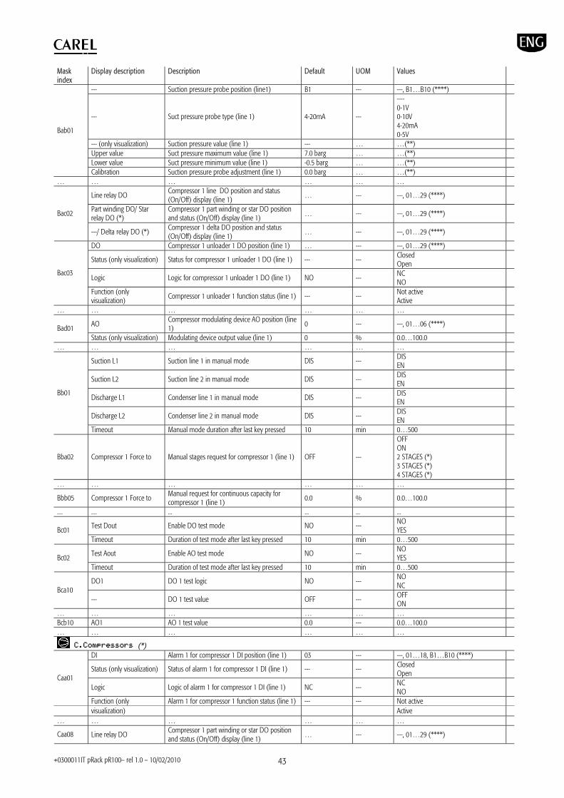
+0300011IT pRack pR100– rel 1.0 – 10/02/2010 43
Mask index
Display description Description Default UOM Values
--- Suction pressure probe position (line1) B1 --- ---, B1…B10 (****)
--- Suct pressure probe type (line 1) 4-20mA ---
---- 0-1V 0-10V 4-20mA 0-5V
--- (only visualization) Suction pressure value (line 1) --- … …(**) Upper value Suct pressure maximum value (line 1) 7.0 barg … …(**) Lower value Suct pressure minimum value (line 1) -0.5 barg … …(**)
Bab01
Calibration Suction pressure probe adjustment (line 1) 0.0 barg … …(**) … … … … … …
Line relay DO Compressor 1 line DO position and status (On/Off) display (line 1) … --- ---, 01…29 (****)
Part winding DO/ Star relay DO (*)
Compressor 1 part winding or star DO position and status (On/Off) display (line 1)
… --- ---, 01…29 (****) Bac02
---/ Delta relay DO (*) Compressor 1 delta DO position and status (On/Off) display (line 1)
… --- ---, 01…29 (****)
DO Compressor 1 unloader 1 DO position (line 1) … --- ---, 01…29 (****)
Status (only visualization) Status for compressor 1 unloader 1 DO (line 1) --- --- Closed Open
Logic Logic for compressor 1 unloader 1 DO (line 1) NO --- NC NO
Bac03
Function (only visualization)
Compressor 1 unloader 1 function status (line 1) --- --- Not active Active
… … … … … …
AO Compressor modulating device AO position (line 1) 0 --- ---, 01…06 (****) Bad01
Status (only visualization) Modulating device output value (line 1) 0 % 0.0…100.0 … … … … … …
Suction L1 Suction line 1 in manual mode DIS --- DIS EN
Suction L2 Suction line 2 in manual mode DIS --- DIS EN
Discharge L1 Condenser line 1 in manual mode DIS --- DIS EN
Discharge L2 Condenser line 2 in manual mode DIS --- DIS EN
Bb01
Timeout Manual mode duration after last key pressed 10 min 0…500
Bba02 Compressor 1 Force to Manual stages request for compressor 1 (line 1) OFF ---
OFF ON 2 STAGES (*) 3 STAGES (*) 4 STAGES (*)
… … … … … …
Bbb05 Compressor 1 Force to Manual request for continuous capacity for compressor 1 (line 1) 0.0 % 0.0…100.0
.... .... ... ... ... ...
Test Dout Enable DO test mode NO --- NO YES Bc01
Timeout Duration of test mode after last key pressed 10 min 0…500
Test Aout Enable AO test mode NO --- NO YES Bc02
Timeout Duration of test mode after last key pressed 10 min 0…500
DO1 DO 1 test logic NO --- NO NC
Bca10 --- DO 1 test value OFF --- OFF
ON … … … … … … Bcb10 AO1 AO 1 test value 0.0 --- 0.0…100.0 … … … … … …
(*) DI Alarm 1 for compressor 1 DI position (line 1) 03 --- ---, 01…18, B1…B10 (****)
Status (only visualization) Status of alarm 1 for compressor 1 DI (line 1) --- --- Closed Open
Logic Logic of alarm 1 for compressor 1 DI (line 1) NC --- NC NO
Caa01
Function (only Alarm 1 for compressor 1 function status (line 1) --- --- Not active visualization) Active … … … … … …
Caa08 Line relay DO Compressor 1 part winding or star DO position and status (On/Off) display (line 1)
… --- ---, 01…29 (****)

+0300011IT pRack pR100– rel 1.0 – 10/02/2010 44
Mask index
Display description Description Default UOM Values
Part winding DO/ Star relay DO (*)
Compressor 1 delta DO position and status (On/Off) display (line 1)
… --- ---, 01…29 (****)
---/ Delta relay DO (*) Compressor 1 line DO position and status (On/Off) display (line 1) … --- ---, 01…29 (****)
… … … … … …
DO Unloader 1 for compressor 1 DO position (line 1)
… --- ---, 01…29 (****)
Status (only visualization) Status of unloader 1 for compressor 1 DI (line 1) --- --- Closed Open
Logic Logic of unloader 1 for compressor 1 DI (line 1) NC --- NC NO
Caa09
Function (only visualization)
Unloader 1 for compressor 1 function status (line 1)
--- --- Not active Active
… … … … … …
AO Compressor modulating device AO position (line 1)
0 --- ---, 01…06 (****) Caa14 Status (only visualization) Modulating device output value (line 1) 0 % 0.0…100.0
… … … … … … --- Suction pressure probe position (line1) B1 --- ---, B1…B10 (****)
--- Suct pressure probe type (line 1) 4-20mA ---
---- 0-1V 0-10V 4-20mA 0-5V
--- (only visualization) Suction temperature value (line 1) --- … …(**) Upper value Suct pressure maximum limit (line 1) 7.0 barg … …(**) Lower value Suct pressure minimum limit (line 1) -0.5 barg … …(**)
Caaa1
Calibration Suction pressure probe adjustment (line 1) 0.0 barg … …(**) … … … … … …
Regulation by Compressor control by temperature or pressure (line 1) PRESSURE --- PRESSURE
TEMPERATURE Cab01
Regulation type Compressor control type (line 1) DEAD ZONE --- PROPORTIONAL BAND DEAD ZONE
Minimum Compressor setpoint lower limit (line 1) …(**) … …(**) Cab02 Maximum Compressor setpoint higher limit (line 1) …(**) … …(**)
Cab03 Setpoint Compressor setpoint (line 1) …(**) … …(**)
Reg.type Type for proportional control (line 1) PROPORTIONAL --- PROPORTIONAL PROP.+INT.
Cab04/Cab6 (**)
Integral time Integral time for proportional control (line 1) 300 s 0…999 Cab05/Cab7 (**) Differential Differential for proportional control (line 1) …(**) … …(**)
NZ diff. Dead zone control differential (line 1) …(**) … …(**)
Activ.diff. Dead zone control differential for device activation (line 1)
…(**) … …(**) Cab08/Cab10 (**)
Deact.diff. Dead zone control differential for device deactivation (line 1)
…(**) … …(**)
En.force off power Enable capacity immediate decreasing to 0 (line 1) NO --- NO
YES Cab09/Cab11 (**)
Setp.for force off Threshold for capacity decreasing to 0 (line 1) …(**) … …(**) Power load to 100% min time
Minimum time to increase capacity request to 100%, dead zone control (suction line 1)
15 s 0…9999 Cab12
Power load to 100% max time
Maximum time to increase capacity request to 100%, dead zone control (suction line 1)
90 s 0…9999
Power unload to 0% min time
Minimum time to decrease capacity request to 0%, dead zone control (suction line 1) 30 s 0…9999
Cab13 Power unload to 0% max time
Maximum time to decrease capacity request to 0%, dead zone control (suction line 1)
180 s 0…9999
Compressor 1 Working hours
Compressor 1 operating hours (line 1) --- --- 0…999999 Cac01 (Check in …) Compressor 1 remaining operating hours (line 1) … --- 0…999999
… … … … … …
Cac13 Compressor threshold Working hours
Compressor maintenance threshold hours (line 1) 88000 --- 0…9999999
Cac14 Compressor hours reset Reset compressor operating hours (line 1) N --- N Y
Cad01 Enable suction setpoint compensation
Enable setpoint compensation (suction line 1) NO --- NO YES
Winter offset Offset applied for Winter period 0.0 … -999.9…999.9 Cad02 Closing offset Offset applied for closing period 0.0 … -999.9…999.9
Cad03 Enable setpoint compensation by
Enable scheduler setpoint compensation (suction line 1) NO --- NO
YES

+0300011IT pRack pR100– rel 1.0 – 10/02/2010 45
Mask index
Display description Description Default UOM Values
scheduler
TB1: --:-- -> --:-- Time band 1 enabling and definition: start hour and minute, end hour and minute (suction line 1)
--- … …
… … … … …
TB4: --:-- -> --:-- Time band 4 enabling and definition: start hour and minute, end hour and minute (suction line 1)
--- … …
Changes Time band change action --- ---
--- CONFIRM&SAVE LOAD PREVIOUS CLEAR ALL
Cad04
Copy to Copy settings to other days 0 --- MONDAY...SUNDAY; MON-FRI; MON-SAT; SAT&SUN; ALL DAYS
Cad05 Change set by DI Enable setpoint compensation by digital input (suct/cond line 1)
NO --- NO YES
Cad08 Enable floating suction setpoint
Enable floating setpoint (suction line 1) NO --- NO YES
Maximum floating setpoint
Max compressor floating setpoint settable (line 1) …(**) … …(**)
Cad09 Minimum floating setpoint Minimum compressor floating setpoint settable
(line 1) …(**) … …(**)
Max.setpoint variation accepted
Maximum delta admitted for floating setpoint (suction line 1)
…(**) … …(**) Cad10
Offline decreasing time Reduction time when supervisor is offline for floating setpoint (suction line 1) 0 min 0…999
Cae01 Number of alarms for each compressor
Number of alarms for each compressor (line 1) 1/4 (*) --- 0…4/7 (*)
Cae02 Alarm1 description Selection of the first compressor alarm description: Generic, Overload, High pressure, Low pressure, Oil (line 1)
… --- (Not available) (Not selected) (Selected)
Cae03 Alarm1 description (*) Selection of the first compressor alarm description: Rotation, Oil warning (line 1)
… --- (Not available) (Not selected) (Selected)
Activ.delay Activation delay for compressor alarm 1 during working (line 1) 0 s 0…999
Start up delay Activation delay for compressor alarm 1 at start up (line 1)
0 s 0…999
Reset Type of reset for compressor alarm 1 (line 1) AUT. --- AUT. MAN.
Cae04
Priority Type of priority for compressor alarm 1 (line 1) SERIOUS --- LIGHT SERIOUS
… … … … … … High alarm High suction pressure alarm threshold …(**) … …(**) Cae24 Alarm diff. High suction pressure alarm differential …(**) … …(**) Suction pressure high alarm
Type of high suction pressure alarm threshold ABSOLUTE --- ABSOLUTE RELATIVE Cae25
Alarm delay High suction pressure alarm delay 120 s 0…999 Low alarm Low suction pressure alarm threshold …(**) … …(**) Cae26 Alarm diff. Low suction pressure alarm differential …(**) … …(**) Suction pressure low alarm
Type of low suction pressure alarm threshold ABSOLUTE --- ABSOLUTE RELATIVE Cae27
Alarm delay Low suction pressure alarm delay 30 s 0…999 Enable oil temperature alarm management (*)
Enable Digital Scroll oil temperature alarm (line 1)
NO --- NO YES
Cae28 Enable discharge temp. alarm management (*)
Enable Digital Scroll discharge temperature alarm (line 1)
NO --- NO YES
Low superheat alarm threshold Threshold for low superheat alarm (line 1) 3.0 K 0.0…99.9
Alarm diff. Low superheat alarm differential (line 1) 1.0 K 0.0…9.9 Cae29
Alarm delay Low superheat alarm delay (line 1) 30 s 0…999 Time of semi-automatic alarm evaluation
Time of semi-automatic alarm evaluation for screw compressors out of envelope (line 1)
2 min 0…999 Cae30
N° of retries before alarms becomes manual
Number of retries before alarm becomes manual (line 1) 3 --- 0…9
Compressors type Type of compressors (line 1) RECIPROCATING --- RECIPROCATING SCROLL SCREW Caf02
Compressors number Number of compressors (line 1) 2/3 (*) --- 1…6/12 (*)
Caf03 Cmp1,… Enable compressors (line 1) EN --- EN DIS
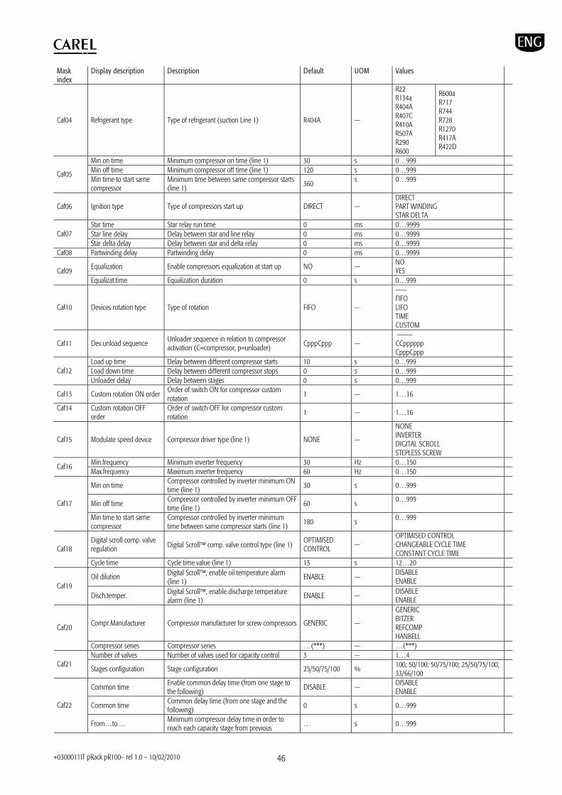
+0300011IT pRack pR100– rel 1.0 – 10/02/2010 46
Mask index
Display description Description Default UOM Values
Caf04 Refrigerant type Type of refrigerant (suction Line 1) R404A ---
R22 R134a R404A R407C R410A R507A R290 R600
R600a R717 R744 R728 R1270 R417A R422D
Min on time Minimum compressor on time (line 1) 30 s 0…999 Min off time Minimum compressor off time (line 1) 120 s 0…999 Caf05 Min time to start same compressor
Minimum time between same compressor starts (line 1) 360 s 0…999
Caf06 Ignition type Type of compressors start up DIRECT --- DIRECT PART WINDING STAR DELTA
Star time Star relay run time 0 ms 0…9999 Star line delay Delay between star and line relay 0 ms 0…9999 Caf07 Star delta delay Delay between star and delta relay 0 ms 0…9999
Caf08 Partwinding delay Partwinding delay 0 ms 0…9999
Equalization Enable compressors equalization at start up NO --- NO YES Caf09
Equalizat.time Equalization duration 0 s 0…999
Caf10 Devices rotation type Type of rotation FIFO ---
------ FIFO LIFO TIME CUSTOM
Caf11 Dev.unload sequence Unloader sequence in relation to compressor activation (C=compressor, p=unloader)
CpppCppp --- -------- CCpppppp CpppCppp
Load up time Delay between different compressor starts 10 s 0…999 Load down time Delay between different compressor stops 0 s 0…999 Caf12 Unloader delay Delay between stages 0 s 0…999
Caf13 Custom rotation ON order Order of switch ON for compressor custom rotation
1 --- 1…16
Caf14 Custom rotation OFF order
Order of switch OFF for compressor custom rotation
1 --- 1…16
Caf15 Modulate speed device Compressor driver type (line 1) NONE ---
NONE INVERTER DIGITAL SCROLL STEPLESS SCREW
Min.frequency Minimum inverter frequency 30 Hz 0…150 Caf16 Max.frequency Maximum inverter frequency 60 Hz 0…150
Min on time Compressor controlled by inverter minimum ON time (line 1) 30 s 0…999
Min off time Compressor controlled by inverter minimum OFF time (line 1)
60 s 0…999 Caf17
Min time to start same compressor
Compressor controlled by inverter minimum time between same compressor starts (line 1)
180 s 0…999
Digital scroll comp. valve regulation Digital Scroll comp. valve control type (line 1)
OPTIMISED CONTROL ---
OPTIMISED CONTROL CHANGEABLE CYCLE TIME CONSTANT CYCLE TIME Caf18
Cycle time Cycle time value (line 1) 13 s 12…20
Oil dilution Digital Scroll, enable oil temperature alarm (line 1)
ENABLE --- DISABLE ENABLE
Caf19 Disch.temper. Digital Scroll, enable discharge temperature
alarm (line 1) ENABLE --- DISABLE
ENABLE
Compr.Manufacturer Compressor manufacturer for screw compressors GENERIC ---
GENERIC BITZER REFCOMP HANBELL
Caf20
Compressor series Compressor series …(***) --- …(***) Number of valves Number of valves used for capacity control 3 --- 1…4
Caf21 Stages configuration Stage configuration 25/50/75/100 % 100; 50/100; 50/75/100; 25/50/75/100;
33/66/100
Common time Enable common delay time (from one stage to the following)
DISABLE --- DISABLE ENABLE
Common time Common delay time (from one stage and the following)
0 s 0…999 Caf22
From…to… Minimum compressor delay time in order to reach each capacity stage from previous … s 0…999
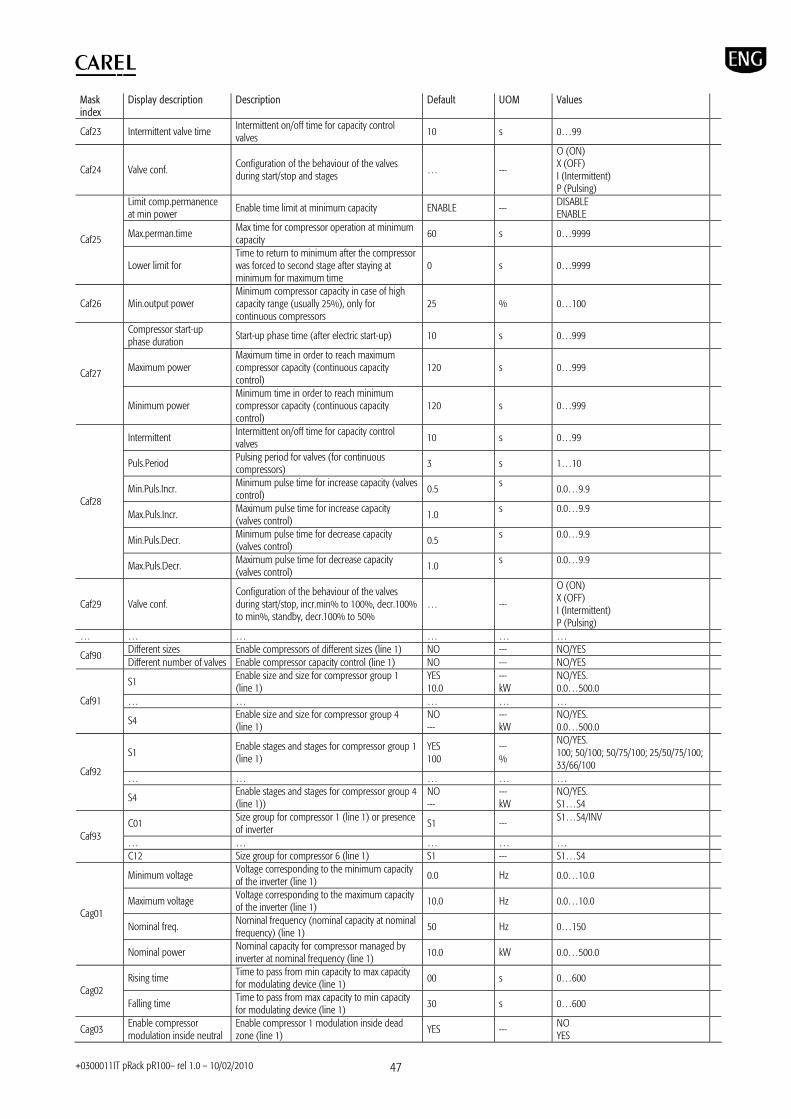
+0300011IT pRack pR100– rel 1.0 – 10/02/2010 47
Mask index
Display description Description Default UOM Values
Caf23 Intermittent valve time Intermittent on/off time for capacity control valves
10 s 0…99
Caf24 Valve conf. Configuration of the behaviour of the valves during start/stop and stages … ---
O (ON) X (OFF) I (Intermittent) P (Pulsing)
Limit comp.permanence at min power Enable time limit at minimum capacity ENABLE --- DISABLE
ENABLE
Max.perman.time Max time for compressor operation at minimum capacity
60 s 0…9999 Caf25
Lower limit for Time to return to minimum after the compressor was forced to second stage after staying at minimum for maximum time
0 s 0…9999
Caf26 Min.output power Minimum compressor capacity in case of high capacity range (usually 25%), only for continuous compressors
25 % 0…100
Compressor start-up phase duration Start-up phase time (after electric start-up) 10 s 0…999
Maximum power Maximum time in order to reach maximum compressor capacity (continuous capacity control)
120 s 0…999 Caf27
Minimum power Minimum time in order to reach minimum compressor capacity (continuous capacity control)
120 s 0…999
Intermittent Intermittent on/off time for capacity control valves
10 s 0…99
Puls.Period Pulsing period for valves (for continuous compressors) 3 s 1…10
Min.Puls.Incr. Minimum pulse time for increase capacity (valves control)
0.5 s 0.0…9.9
Max.Puls.Incr. Maximum pulse time for increase capacity (valves control)
1.0 s 0.0…9.9
Min.Puls.Decr. Minimum pulse time for decrease capacity (valves control) 0.5 s 0.0…9.9
Caf28
Max.Puls.Decr. Maximum pulse time for decrease capacity (valves control)
1.0 s 0.0…9.9
Caf29 Valve conf. Configuration of the behaviour of the valves during start/stop, incr.min% to 100%, decr.100% to min%, standby, decr.100% to 50%
… ---
O (ON) X (OFF) I (Intermittent) P (Pulsing)
… … … … … … Different sizes Enable compressors of different sizes (line 1) NO --- NO/YES Caf90 Different number of valves Enable compressor capacity control (line 1) NO --- NO/YES
S1 Enable size and size for compressor group 1 (line 1)
YES 10.0
--- kW
NO/YES. 0.0…500.0
… … … … … Caf91
S4 Enable size and size for compressor group 4 (line 1)
NO ---
--- kW
NO/YES. 0.0…500.0
S1 Enable stages and stages for compressor group 1 (line 1)
YES 100
--- %
NO/YES. 100; 50/100; 50/75/100; 25/50/75/100; 33/66/100
… … … … … Caf92
S4 Enable stages and stages for compressor group 4 (line 1))
NO ---
--- kW
NO/YES. S1…S4
C01 Size group for compressor 1 (line 1) or presence of inverter
S1 --- S1…S4/INV
… … … … … Caf93
C12 Size group for compressor 6 (line 1) S1 --- S1…S4
Minimum voltage Voltage corresponding to the minimum capacity of the inverter (line 1)
0.0 Hz 0.0…10.0
Maximum voltage Voltage corresponding to the maximum capacity of the inverter (line 1) 10.0 Hz 0.0…10.0
Nominal freq. Nominal frequency (nominal capacity at nominal frequency) (line 1)
50 Hz 0…150 Cag01
Nominal power Nominal capacity for compressor managed by inverter at nominal frequency (line 1)
10.0 kW 0.0…500.0
Rising time Time to pass from min capacity to max capacity for modulating device (line 1) 00 s 0…600
Cag02 Falling time Time to pass from max capacity to min capacity
for modulating device (line 1) 30 s 0…600
Cag03 Enable compressor modulation inside neutral
Enable compressor 1 modulation inside dead zone (line 1)
YES --- NO YES

+0300011IT pRack pR100– rel 1.0 – 10/02/2010 48
Mask index
Display description Description Default UOM Values
zone
Cag04 Enable suction press.backup probe
Enable screens for suction pressure backup probe configuration (line 1)
NO --- NO YES
Cag05 Regulation value in case of probe fault
Compressor forcing value in case of suction probes fault (line 1) 50.0 % 0.0…100.0
Cag06 Enable anti return of liquid Enable liquid non return function (line 1) NO --- NO YES
Cag07 Enable compressor envelop management (*)
Enable compressor envelope management NO --- NO YES
The following parameters refer to line 2, for details see the corresponding parameters for line 1 above DI Alarm 1 for compressor 1 DI position (line 2) 03 --- ---, 01…18, B1…B10 (****)
Status (only visualization) Status of alarm 1 for compressor 1 DI (line 2) --- --- Closed Open
Logic Logic of alarm 1 for compressor 1 DI (line 2) NC --- NC NO
Cba01
Function (only visualization)
Alarm 1 for compressor 1 function status (line 2) --- --- Not active Active
… … … … … …
Regulation by Compressor control by temperature or pressure (line 2) PRESSURE --- PRESSURE
TEMPERATURE Cbb01
Regulation type Compressor control type (line 2) DEAD ZONE --- PROPORTIONAL BAND DEAD ZONE
… … … … … …
Cbc01 Compressor 1 Working hours
Compressor 1 max operating hours (line 2) 0 --- 0…999999
… … … … … …
Cbd01 Enable suction setpoint compensation Enable setpoint compensation (suction line 2) NO --- NO
YES
… … … … … …
Cbe01 Number of alarms for each compressor
Number of alarms for each compressor (line 2) 0 --- 0…7 (*)
… … … … … …
Compressors type Type of compressors (line 1) RECIPROCATING --- RECIPROCATING SCROLL SCREW Cbf02
Compressors number Number of compressors (line 1) 2/3 (*) --- 1…6/12 (*) … … … … … …
Mininum voltage Voltage corresponding at the minimum capacity of the inverter (line 1)
0.0 Hz 0.0…10.0
Maximum voltage Voltage corresponding at the maximum capacity of the inverter (line 1) 10.0 Hz 0.0…10.0
Nominal freq. Nominal frequency (nominal capacity at nominal frequency) (line 1)
50 Hz 0…150 Cbg01
Nominal power Nominal capacity for compressor managed by inverter at nominal frequency (line 1)
10.0 kW 0.0…500.0
… … … … … …
DI Fan 1 overload DI position (line 1) … --- ---, 01…18, B1…B10 (****)
Status (only visualization) Status of fan 1 overload DI (line 1) --- --- Closed Open
Logic Logic of fan 1 overload DI (line 1) NC --- NC NO
Daa01
Function (only visualization)
Fan 1 overload function status (line 1) --- --- Not active Active
… … … … … …
--- Condensing pressure backup probe position (line1)
B1 --- ---, B1…B10 (****)
--- Condensing pressure backup probe type (line 1) 4-20mA ---
---- 0-1V 0-10V 4-20mA 0-5V
--- (only visualization) Condensing pressure backup probe value (line 1)
--- … …(**)
Upper value Cond. pressure backup probe max. limit (line 1) 30.0 barg … …(**) Lower value Cond. pressure backup probe min. limit (line 1) 0.0 barg … …(**)
Daa18
Calibration Cond. pressure backup probe adjustment (line 1)
0.0 barg … …(**)
… … … … … … Daa21 DO Fan 1 DO position (line 1) 03 --- ---, 01…29 (****)
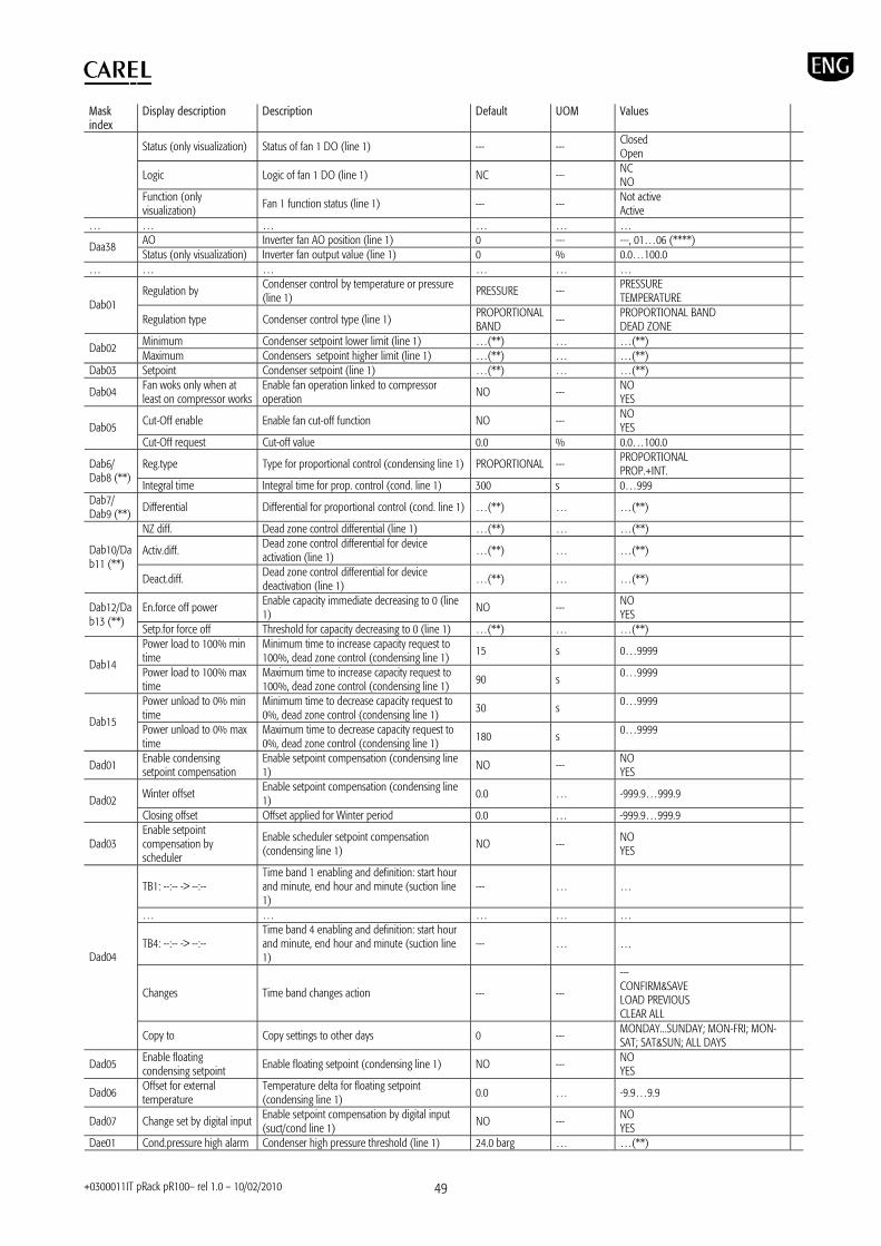
+0300011IT pRack pR100– rel 1.0 – 10/02/2010 49
Mask index
Display description Description Default UOM Values
Status (only visualization) Status of fan 1 DO (line 1) --- --- Closed Open
Logic Logic of fan 1 DO (line 1) NC --- NC NO
Function (only visualization)
Fan 1 function status (line 1) --- --- Not active Active
… … … … … … AO Inverter fan AO position (line 1) 0 --- ---, 01…06 (****) Daa38 Status (only visualization) Inverter fan output value (line 1) 0 % 0.0…100.0
… … … … … …
Regulation by Condenser control by temperature or pressure (line 1)
PRESSURE --- PRESSURE TEMPERATURE Dab01
Regulation type Condenser control type (line 1) PROPORTIONAL BAND --- PROPORTIONAL BAND
DEAD ZONE Minimum Condenser setpoint lower limit (line 1) …(**) … …(**) Dab02 Maximum Condensers setpoint higher limit (line 1) …(**) … …(**)
Dab03 Setpoint Condenser setpoint (line 1) …(**) … …(**)
Dab04 Fan woks only when at least on compressor works
Enable fan operation linked to compressor operation
NO --- NO YES
Cut-Off enable Enable fan cut-off function NO --- NO YES Dab05
Cut-Off request Cut-off value 0.0 % 0.0…100.0
Reg.type Type for proportional control (condensing line 1) PROPORTIONAL --- PROPORTIONAL PROP.+INT. Dab6/
Dab8 (**) Integral time Integral time for prop. control (cond. line 1) 300 s 0…999
Dab7/ Dab9 (**)
Differential Differential for proportional control (cond. line 1) …(**) … …(**)
NZ diff. Dead zone control differential (line 1) …(**) … …(**)
Activ.diff. Dead zone control differential for device activation (line 1)
…(**) … …(**) Dab10/Dab11 (**)
Deact.diff. Dead zone control differential for device deactivation (line 1) …(**) … …(**)
En.force off power Enable capacity immediate decreasing to 0 (line 1)
NO --- NO YES
Dab12/Dab13 (**)
Setp.for force off Threshold for capacity decreasing to 0 (line 1) …(**) … …(**) Power load to 100% min time
Minimum time to increase capacity request to 100%, dead zone control (condensing line 1)
15 s 0…9999 Dab14
Power load to 100% max time
Maximum time to increase capacity request to 100%, dead zone control (condensing line 1) 90 s 0…9999
Power unload to 0% min time
Minimum time to decrease capacity request to 0%, dead zone control (condensing line 1)
30 s 0…9999
Dab15 Power unload to 0% max time
Maximum time to decrease capacity request to 0%, dead zone control (condensing line 1)
180 s 0…9999
Dad01 Enable condensing setpoint compensation
Enable setpoint compensation (condensing line 1) NO --- NO
YES
Winter offset Enable setpoint compensation (condensing line 1)
0.0 … -999.9…999.9 Dad02 Closing offset Offset applied for Winter period 0.0 … -999.9…999.9
Dad03 Enable setpoint compensation by scheduler
Enable scheduler setpoint compensation (condensing line 1)
NO --- NO YES
TB1: --:-- -> --:-- Time band 1 enabling and definition: start hour and minute, end hour and minute (suction line 1)
--- … …
… … … … …
TB4: --:-- -> --:-- Time band 4 enabling and definition: start hour and minute, end hour and minute (suction line 1)
--- … …
Changes Time band changes action --- ---
--- CONFIRM&SAVE LOAD PREVIOUS CLEAR ALL
Dad04
Copy to Copy settings to other days 0 --- MONDAY...SUNDAY; MON-FRI; MON-SAT; SAT&SUN; ALL DAYS
Dad05 Enable floating condensing setpoint Enable floating setpoint (condensing line 1) NO --- NO
YES
Dad06 Offset for external temperature
Temperature delta for floating setpoint (condensing line 1)
0.0 … -9.9…9.9
Dad07 Change set by digital input Enable setpoint compensation by digital input (suct/cond line 1)
NO --- NO YES
Dae01 Cond.pressure high alarm Condenser high pressure threshold (line 1) 24.0 barg … …(**)
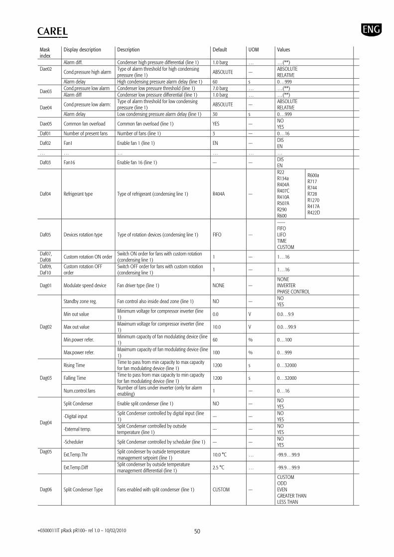
+0300011IT pRack pR100– rel 1.0 – 10/02/2010 50
Mask index
Display description Description Default UOM Values
Alarm diff. Condenser high pressure differential (line 1) 1.0 barg … …(**)
Cond.pressure high alarm Type of alarm threshold for high condensing pressure (line 1)
ABSOLUTE --- ABSOLUTE RELATIVE
Dae02
Alarm delay High condensing pressure alarm delay (line 1) 60 s 0…999 Cond.pressure low alarm Condenser low pressure threshold (line 1) 7.0 barg … …(**) Dae03 Alarm diff Condenser low pressure differential (line 1) 1.0 barg … …(**)
Cond.pressure low alarm: Type of alarm threshold for low condensing pressure (line 1) ABSOLUTE --- ABSOLUTE
RELATIVE Dae04 Alarm delay Low condensing pressure alarm delay (line 1) 30 s 0…999
Dae05 Common fan overload Common fan overload (line 1) YES --- NO YES
Daf01 Number of present fans Number of fans (line 1) 3 --- 0…16
Daf02 Fan1 Enable fan 1 (line 1) EN --- DIS EN
… … … … … …
Daf03 Fan16 Enable fan 16 (line 1) --- --- DIS EN
Daf04 Refrigerant type Type of refrigerant (condensing line 1) R404A ---
R22 R134a R404A R407C R410A R507A R290 R600
R600a R717 R744 R728 R1270 R417A R422D
Daf05 Devices rotation type Type of rotation devices (condensing line 1) FIFO ---
------ FIFO LIFO TIME CUSTOM
Daf07, Daf08 Custom rotation ON order Switch ON order for fans with custom rotation
(condensing line 1) 1 --- 1…16
Daf09, Daf10
Custom rotation OFF order
Switch OFF order for fans with custom rotation (condensing line 1)
1 --- 1…16
Dag01 Modulate speed device Fan driver type (line 1) NONE --- NONE INVERTER PHASE CONTROL
Standby zone reg. Fan control also inside dead zone (line 1) NO --- NO YES
Min out value Minimum voltage for compressor inverter (line 1)
0.0 V 0.0…9.9
Max out value Maximum voltage for compressor inverter (line 1) 10.0 V 0.0…99.9
Min.power refer. Minimum capacity of fan modulating device (line 1)
60 % 0…100
Dag02
Max.power refer. Maximum capacity of fan modulating device (line 1)
100 % 0…999
Rising Time Time to pass from min capacity to max capacity for fan modulating device (line 1) 1200 s 0…32000
Falling Time Time to pass from max capacity to min capacity for fan modulating device (line 1)
1200 s 0…32000 Dag03
Num.control.fans Number of fans under inverter (only for alarm enabling)
1 --- 0…16
Split Condenser Enable split condenser (line 1) NO --- NO YES
-Digital input Split Condenser controlled by digital input (line 1)
--- --- NO YES
-External temp. Split Condenser controlled by outside temperature (line 1)
--- --- NO YES
Dag04
-Scheduler Split Condenser controlled by scheduler (line 1) --- --- NO YES
Ext.Temp.Thr Split condenser by outside temperature management setpoint (line 1)
10.0 °C … -99.9…99.9 Dag05
Ext.Temp.Diff Split condenser by outside temperature management differential (line 1)
2.5 °C … -99.9…99.9
Dag06 Split Condenser Type Fans enabled with split condenser (line 1) CUSTOM ---
CUSTOM ODD EVEN GREATER THAN LESS THAN

+0300011IT pRack pR100– rel 1.0 – 10/02/2010 51
Mask index
Display description Description Default UOM Values
--- Only when enabling type is GREATER THAN or LESS THAN, number of fans to consider for splitting (line 1)
0 --- 0…16
TB1: --:-- -> --:-- Time band 1 enabling and definition: start hour and minute, end hour and minute (condensing line 1)
--- … …
… … … … …
TB4: --:-- -> --:-- Time band 4 enabling and definition: start hour and minute, end hour and minute (condensing line 1)
--- … …
Changes Time band changes action --- ---
--- CONFIRM&SAVE LOAD PREVIOUS CLEAR ALL
Dag08
Copy to Copy settings to other days 0 --- MONDAY...SUNDAY; MON-FRI; MON-SAT; SAT&SUN; ALL DAYS
Disable split condenser as first stage of HP pressostat
Disable split condenser when high condensing pressure prevent occurs (line 1) NO --- NO
YES Dag09
for Duration of split condenser deactivation for high condensing pressure prevent (line 1)
0 h 0…24
Anti-noise Enable silencer (line 1) DISABLED --- DISABLED ENABLED
Max output Maximum request allowed when silencer function is active (line 1) 75.0 % % 0.0…100.0
-Digital input Silencer controlled by digital input (condensing line 1)
NO --- NO YES
Dag10
-Scheduler Silencer controlled by scheduler (condensing line 1)
NO --- NO YES
TB1: --:-- -> --:-- Time band 1 enabling and definition: start hour and minute, end hour and minute (condensing line 1)
--- … …
… … … … …
TB4: --:-- -> --:-- Time band 4 enabling and definition: start hour and minute, end hour and minute (condensing line 1)
--- … …
Changes Time band changes action --- ---
--- CONFIRM&SAVE LOAD PREVIOUS CLEAR ALL
Dag12
Copy to Copy settings to other days 0 --- MONDAY...SUNDAY; MON-FRI; MON-SAT; SAT&SUN; ALL DAYS
Speed Up Enable speed up (condensing line 1) YES --- NO YES
Speed Up time Speed up time (condensing line 1) 5 s 0…60
Ext.Temp.Manage Enable speed up management by outside temperature (condensing line 1) DIS --- DIS
EN
Ext.Temp.Thr. Outside temperature threshold for speed up management (condensing line 1)
25.0 °C … -99.9…99.9
Dag13
Ext.Temp.Diff. Outside temperature differential for speed up management (condensing line 1)
2.5 °C … -99.9…99.9
Dag14 Enable Condensing press.backup probe
Enable the screens for condensing pressure backup probe configuration (condensing line 1) NO --- NO
YES
Dag15 Regulation value in case of probe fault
Value of fans forcing in case of condensing probes fault (line 1)
50.0 % 0.0…100.0
The following parameters refer to line 2, for details see the corresponding parameters for line 1 above DI Fan 1 overload DI position (line 1) … --- ---, 01…18, B1…B10 (****)
Status (only visualization) Status of fan 1 overload DI (line 1) --- --- Closed Open
Logic Logic of fan 1 overload DI (line 1) NC --- NC NO
Dba01
Function (only visualization) Fan 1 overload function status (line 1) --- --- Not active
Active … … … … … …
Regulation by Condenser control by temperature or pressure (line 1)
PRESSURE --- PRESSURE TEMPERATURE Dbb01
Regulation type Condenser control type (line 1) PROPORTIONAL BAND
--- PROPORTIONAL BAND DEAD ZONE
… … … … … …
Dbd01 Enable condensing setpoint compensation
Enable setpoint compensation (condensing line 1) NO --- NO
YES
… … … … … … Dbe01 Cond.pressure high alarm Condenser high pressure threshold (line 1) 24.0 barg … …(**)

+0300011IT pRack pR100– rel 1.0 – 10/02/2010 52
Mask index
Display description Description Default UOM Values
Alarm diff. Condenser high pressure differential (line 1) 1.0 barg … …(**) … … … … … … Dbf01 Number of present fans Number of fans (line 1) 3 --- 0…16 … … … … … …
Dbg01 Modulate speed device Fan driver type (line 1) NONE --- NONE INVERTER PHASE CONTROL
… … … … … …
--- Oil temperature probe position (line1) B1 --- ---, B1…B10 (****)
--- Oil temperature probe type (line 1) 4-20mA ---
--- NTC PT1000 0-1V 0-10V 4-20mA 0-5V HTNTC
--- (only visualization) Oil temperature probe value (line 1) --- … …(**) Upper value Oil temperature probe max. limit (line 1) 30.0 barg … …(**) Lower value Oil temperature probe min. limit (line 1) 0.0 barg … …(**)
Eaaa04
Calibration Oil temperature probe adjustment (line 1) 0.0 barg … …(**) … … … … … …
Oil pumps number Number of oil pumps for common oil cooler (line 1)
0 --- 0…1 (analogue output) 0…2 (digital output) Eaab04
Enable Aout pump Enable AO of common oil cooler pump (line 1) YES --- NO (digital output) YES (analogue output)
Setpoint Common oil cooler setpoint (line 1) 0.0 °C … …(**) Eaab05 Differential Common oil cooler differential (line 1) 0.0 °C … -9.9…9.9
Eaab06 Pump start delay Time delay before the start-up of pump 2 after pump1 turns on (line 1) 0 s 0…999
Oil pumps number Screw compressors: number of oil cooler pumps enabled (line1)
0 --- 0…1 (analogue output) 0…2 (digital output) Eaab07
Enable Aout pump Screw compressors: enable AO for oil cooler pump (line 1)
YES --- NO (digital output) YES (analogue output)
Setpoint Screw compressors: oil temperature setpoint (line 1) 0.0 °C/°F …
Eaab08 Differential Screw compressors: oil temperature differential
(line 1) 0.0 °C/°F …
Threshold Common oil high temperature alarm threshold (line 1)
100.0 °C °C/°F …
Differential Common oil high temperature alarm differential (line 1) 10.0 °C °C/°F … Eaab09
Delay Common oil high temperature alarm delay (line 1) 120.0 °C s 0…32767
En.oil lev.manag. Enable oil level management (line 1) NO --- NO YES Eaab10
Num.alarm oil level Number of compressor alarm associated with oil level (line 1) 0 --- 0…4/7 (*)
Time open Opening time of the valve for oil level (line 1) 0 s 0…999 Time close Closing time of the valve for oil level (line 1) 0 s 0…999 Eaab11 Time max Maximum time allowed to reach oil level (line 1) 0 s 0…999 DO Subcooling valve DO position (line 1) … --- ---, 01…29 (****)
Status (only visualization) Status of subcooling valve DO (line 1) --- --- Closed Open
Logic Logic of subcooling valve (line 1) NO --- NC NO
Ebaa01
Function (only visualization) Subcooling valve function status (line 1) --- --- Not active
Active
Subcooling contr. Enable subcooling function (line 1) NO --- NO YES
--- Subcooling control type (line 1) BY COND&LIQUID.TEMP.
--- BY COND&LIQUID.TEMP. ONLY BY LIQUID TEMP.
Threshold Threshold for subcooling control (line 1) 0.0 °C … -9999.9…9999.9
Ebab01
Subcooling (only visualization)
Subcooling value (line 1) 0.0 °C … -999.9…999.9
Economizer Enable economizer function (line 1) NO --- NO YES
Ecab04 (*)
Compr.Power Thr. Capacity percentage threshold for economizer activation (line 1)
0 % 0…100
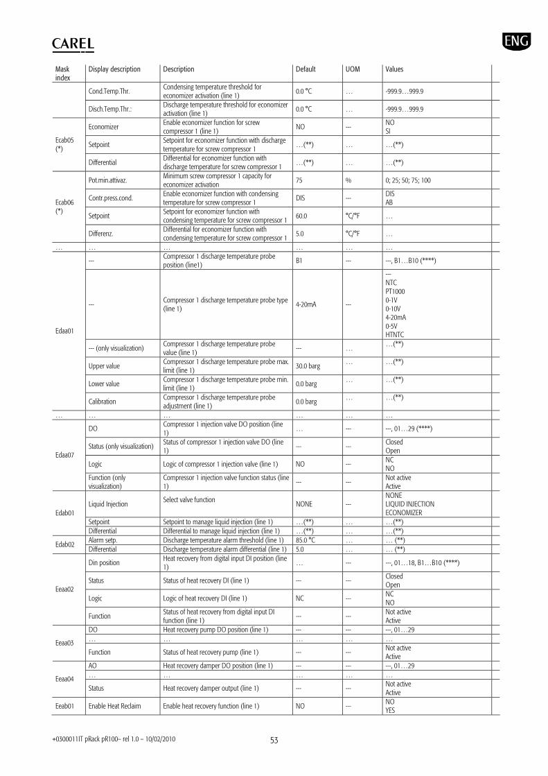
+0300011IT pRack pR100– rel 1.0 – 10/02/2010 53
Mask index
Display description Description Default UOM Values
Cond.Temp.Thr. Condensing temperature threshold for economizer activation (line 1)
0.0 °C … -999.9…999.9
Disch.Temp.Thr.: Discharge temperature threshold for economizer activation (line 1) 0.0 °C … -999.9…999.9
Economizer Enable economizer function for screw compressor 1 (line 1)
NO --- NO SI
Setpoint Setpoint for economizer function with discharge temperature for screw compressor 1
…(**) … …(**) Ecab05 (*)
Differential Differential for economizer function with discharge temperature for screw compressor 1 …(**) … …(**)
Pot.min.attivaz. Minimum screw compressor 1 capacity for economizer activation
75 % 0; 25; 50; 75; 100
Contr.press.cond. Enable economizer function with condensing temperature for screw compressor 1
DIS --- DIS AB
Setpoint Setpoint for economizer function with condensing temperature for screw compressor 1 60.0 °C/°F …
Ecab06 (*)
Differenz. Differential for economizer function with condensing temperature for screw compressor 1
5.0 °C/°F …
… … … … … …
--- Compressor 1 discharge temperature probe position (line1)
B1 --- ---, B1…B10 (****)
--- Compressor 1 discharge temperature probe type (line 1) 4-20mA ---
--- NTC PT1000 0-1V 0-10V 4-20mA 0-5V HTNTC
--- (only visualization) Compressor 1 discharge temperature probe value (line 1)
--- … …(**)
Upper value Compressor 1 discharge temperature probe max. limit (line 1)
30.0 barg … …(**)
Lower value Compressor 1 discharge temperature probe min. limit (line 1) 0.0 barg … …(**)
Edaa01
Calibration Compressor 1 discharge temperature probe adjustment (line 1)
0.0 barg … …(**)
… … … … … …
DO Compressor 1 injection valve DO position (line 1)
… --- ---, 01…29 (****)
Status (only visualization) Status of compressor 1 injection valve DO (line 1) --- --- Closed
Open
Logic Logic of compressor 1 injection valve (line 1) NO --- NC NO
Edaa07
Function (only visualization)
Compressor 1 injection valve function status (line 1)
--- --- Not active Active
Liquid Injection Select valve function NONE ---
NONE LIQUID INJECTION ECONOMIZER
Setpoint Setpoint to manage liquid injection (line 1) …(**) … …(**) Edab01
Differential Differential to manage liquid injection (line 1) …(**) … …(**) Alarm setp. Discharge temperature alarm threshold (line 1) 85.0 °C … … (**) Edab02 Differential Discharge temperature alarm differential (line 1) 5.0 … … (**)
Din position Heat recovery from digital input DI position (line 1)
… --- ---, 01…18, B1…B10 (****)
Status Status of heat recovery DI (line 1) --- --- Closed Open
Logic Logic of heat recovery DI (line 1) NC --- NC NO
Eeaa02
Function Status of heat recovery from digital input DI function (line 1)
--- --- Not active Active
DO Heat recovery pump DO position (line 1) --- --- ---, 01…29 … … … … … Eeaa03 Function Status of heat recovery pump (line 1) --- --- Not active
Active AO Heat recovery damper DO position (line 1) --- --- ---, 01…29 … … … … … Eeaa04 Status Heat recovery damper output (line 1) --- --- Not active
Active
Eeab01 Enable Heat Reclaim Enable heat recovery function (line 1) NO --- NO YES

+0300011IT pRack pR100– rel 1.0 – 10/02/2010 54
Mask index
Display description Description Default UOM Values
Eeab02 Condensing Pressure Lower Limit
Condensing pressure lower limit for heat recovery (line 1)
0.0 barg … … (**)
Eeab03 Modulation by temperature
Enable heat recovery control by discharge temperature (line 1) NO --- NO
YES
Setpoint Heat recovery: discharge temperature setpoint (line 1)
0.0 °C … … (**) Eeab04
Differential Heat recovery: discharge temperature differential (line 1)
0.0 °C … 0.0…99.9
Eeab05 Enable activation by Scheduler
Enable heat recovery control by scheduler (line 1) NO --- NO
YES
TB1: --:-- -> --:-- Time band 1 enabling and definition: start hour and minute, end hour and minute (condensing line 1)
--- … …
… … … … …
TB4: --:-- -> --:-- Time band 4 enabling and definition: start hour and minute, end hour and minute (condensing line 1)
--- … …
Changes Time band changes action --- ---
--- CONFIRM&SAVE LOAD PREVIOUS CLEAR ALL
Eeab06
Copy to Copy settings to other days 0 --- MONDAY...SUNDAY; MON-FRI; MON-SAT; SAT&SUN; ALL DAYS
Gen.Funct.1 Enable generic stage function 1 DISABLE --- DISABLE ENABLE
… .. … … … Efa05
Gen.Funct.5 Enable generic stage function 5 DISABLE --- DISABLE ENABLE
Regulation variable Control variable for generic stage function 1 --- --- … Efa06
Mode Direct or reverse control DIRECT --- DIRECT REVERSE
Enable Enabling variable for generic stage function 1 --- --- …
Description: Enable description change SKIP --- SKIP CHANGE Efa07
--------------- Description --- --- …
Setpoint Setpoint for generic stage function 1 0.0 °C … … (**) Efa08 Differential Differential for generic stage function 1 0.0 °C … … (**)
High alarm High alarm enabling for generic stage function 1 DISABLE --- DISABLE ENABLE
High alarm High alarm threshold for generic stage function 1 0.0 °C … … (**) Delay time High alarm delay for generic stage function 1 0 s 0…9999
Low alarm Low alarm enabling for generic stage function 1 DISABLE --- DISABLE ENABLE
Low alarm Low alarm threshold for generic stage function 1 0.0 °C … … (**)
Efa09
Delay time Low alarm delay for generic stage function 1 0 s 0…9999 … … … … … …
Gen.Modulat.1 Enable generic modulating function 1 management
DISABLE --- DISABLE ENABLE Efb05
Gen.Modulat.2 Enable generic modulating function 2 management
DISABLE --- DISABLE ENABLE
Regulation variable Control variable for generic modulating function 1 --- --- …
Efb06 Mode Direct or reverse modulation DIRECT --- DIRECT
REVERSE
Enable Enabling variable for generic modulating function 1
--- --- …
Description Enable description change SKIP --- SKIP CHANGE
Efb07
--------------- Description --- --- … Setpoint Setpoint for generic modulating function 1 0.0 °C … … (**) Efb08 Differential Differential for generic modulating function 1 0.0 °C … … (**)
High alarm High alarm enabling for generic modulating function 1
DISABLE --- DISABLE ENABLE
High alarm High alarm threshold for generic modulating function 1
0.0 °C … … (**)
Delay time High alarm delay for generic modulating function 1 0 s 0…9999
Efb09
Low alarm Low alarm enabling for generic modulating function 1
DISABLE --- DISABLE ENABLE
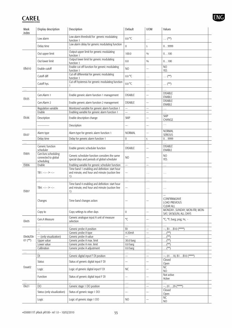
+0300011IT pRack pR100– rel 1.0 – 10/02/2010 55
Mask index
Display description Description Default UOM Values
Low alarm Low alarm threshold for generic modulating function 1
0.0 °C … … (**)
Delay time Low alarm delay for generic modulating function 1 0 s 0…9999
Out upper limit Output upper limit for generic modulating function 1
100.0 % 0…100
Out lower limit Output lower limit for generic modulating function 1
0.0 % 0…100
Enable cutoff Enable cut off function for generic modulating function 1 NO --- NO
YES
Cutoff diff Cut off differential for generic modulating function 1
0.0 °C … … (**)
Efb010
Cutoff hys. Cut off hysteresis for generic modulating function 1
0.0 °C … … (**)
… … … … … …
Gen.Alarm 1 Enable generic alarm function 1 management DISABLE --- DISABLE ENABLE
Efc05 Gen.Alarm 2 Enable generic alarm function 2 management DISABLE --- DISABLE
ENABLE Regulation variable Monitored variable for generic alarm function 1 --- --- … Enable Enabling variable for generic alarm function 1 --- --- …
Description Enable description change SKIP --- SKIP CHANGE
Efc06
--------------- Description --- --- …
Alarm type Alarm type for generic alarm function 1 NORMAL --- NORMAL SERIOUS Efc07
Delay time Delay for generic alarm function 1 0 s 0…9999 … … … … … …
Generic function scheduler
Enable generic scheduler function DISABLE --- DISABLE ENABLE
Efd05 Gen.func.scheduling connected to global scheduling
Generic scheduler function considers the same special days and periods of global scheduler NO --- NO
YES
Efd06 Enable Enabling variable for generic scheduler function --- --- …
TB1: --:-- -> --:-- Time band 1 enabling and definition: start hour and minute, end hour and minute (suction line 1)
--- … …
… … … … …
TB4: --:-- -> --:-- Time band 4 enabling and definition: start hour and minute, end hour and minute (suction line 1)
--- … …
Changes Time band changes action --- ---
--- CONFIRM&SAVE LOAD PREVIOUS CLEAR ALL
Efd07
Copy to Copy settings to other days 0 --- MONDAY...SUNDAY; MON-FRI; MON-SAT; SAT&SUN; ALL DAYS
Gen.A Measure Generic analogue input A unit of measure selection
°C --- °C; °F; barg; psig; %; - Efe05 … … … … … --- Generic probe A position B1 --- ---, B1…B10 (****) --- Generic probe A type 4-20mA --- …(**) --- (only visualization) Generic probe A value --- … …(**) Upper value Generic probe A max. limit 30.0 barg … …(**) Lower value Generic probe A min. limit 0.0 barg … …(**)
Efe06/Efe07 (**)
Calibration Generic probe A adjustment 0.0 barg … …(**) … ... ... … … …
DI Generic digital input F DI position --- --- ---, 01…18, B1…B10 (****)
Status Status of generic digital input F DI --- --- Closed Open
Logic Logic of generic digital input F DI NC --- NC NO
Eeaa02
Function Status of generic digital input F DI --- --- Not active Active
… ... ... … … … DO Generic stage 1 DO position … --- ---, 01…29 (****)
Status (only visualization) Status of generic stage 1 DO --- --- Closed Open
Efe21
Logic Logic of generic stage 1 DO NO --- NC NO

+0300011IT pRack pR100– rel 1.0 – 10/02/2010 56
Mask index
Display description Description Default UOM Values
Function (only visualization)
Generic stage 1 DO function status --- --- Not active Active
… … … … … … Modulating1 Generic modulating 1 AO position 0 --- ---, 01…06 (****) Efe29 Status (only visualization) Generic modulating 1 output value 0 % 0.0…100.0
… … … … … … DI ChillBooster fault DI position (line 1) --- --- ---, 01…18, B1…B10 (****)
Status Status of ChillBooster fault DI (line 1) --- --- Closed Open
Logic Logic of ChillBooster fault DI (line 1) NC --- NC NO
Egaa01
Function Status of ChillBooster fault (line 1) --- --- Not active Active
DO ChillBooster DO position (line 1) … --- ---, 01…29 (****)
Status (only visualization) Status of ChillBooster DO (line 1) --- --- Closed Open
Logic Logic of ChillBooster DO (line 1) NO --- NC NO
Egaa02
Function (only visualization)
Status of ChillBooster function (line 1) --- --- Not active Active
Device present Enable ChillBooster function (line 1) NO --- NO YES
Egab01 Deactivation when fans power falls under
Fan capacity under which ChillBooster is deactivated (line 1)
95 % 0…100
Before the activation, fans at max for
Fans work at maximum capacity at least for this time before ChillBooster activation (line 1)
5 min 0…300 Egab02
Ext.Temp.Thr Outside temperature threshold for ChillBooster activation (line 1) 30.0 °C … …(**)
Sanitary proc. Enable hygiene procedure (line 1) DISABLE --- DISABLE ENABLE
Start at Hygiene procedure starting time (line 1) 00:00 --- … Duration Hygiene procedure duration (line 1) 0 min 0…30
Egab03
Ext.temp.thr Outside temperature threshold for hygiene procedure activation (line 1)
5.0 °C … …(**)
Chillbooster requires maintenance after ChillBooster maximum running time (line 1) 200 h 0…999
Egab04 Reset maintenance time ChilllBooster maintenance time reset (line 1) NO --- NO
YES Avoid simultaneous pulse betw. lines
Enable simultaneous compressor start up inhibition
NO --- NO YES Ehb01
Delay Delay between start up for compressors on different lines 0 s 0…999
Force off L2 Comp.s for line 1 fault
Enable line 2 compressor switch OFF due to line 1 compressor fault
NO --- NO YES Ehb03
Delay Delay for line 2 compressor switch off after serious alarm on line 1 compressors
0 s 0…999
Switch on L1 Comp.s for L2 activation
Enable line 1 compressor switch ON due to line 2 compressor switch ON NO --- NO
YES Ehb04
Delay Delay for line1 compressor switch on for line 2 compressor switch on
0 s 0…999
The following parameters refer to line 2, for details see the corresponding parameters for line 1 above --- Oil temperature probe position (line 2) B1 --- ---, B1…B10 (****)
--- Oil temperature probe type (line 2) 4-20mA ---
--- NTC PT1000 0-1V 0-10V 4-20mA 0-5V HTNTC
--- (only visualization) Oil temperature probe value (line 2) --- … …(**) Upper value Oil temperature probe max. limit (line 2) 30.0 barg … …(**) Lower value Oil temperature probe min. limit (line 2) 0.0 barg … …(**)
Eaba04
Calibration Oil temperature probe adjustment (line 2) 0.0 barg … …(**) … … … … … …
Oil pumps number Number of oil pumps for common oil cooler (line 2) 0 --- 0…1 (analogue output)
0…2 (digital output) Eabb04
Enable Aout pump Enable AO of common oil cooler pump (line 2) YES --- NO (digital output) YES (analogue output)
… … … … … … Ebba01 DO Subcooling valve DO position (line 1) … --- ---, 01…29 (****)
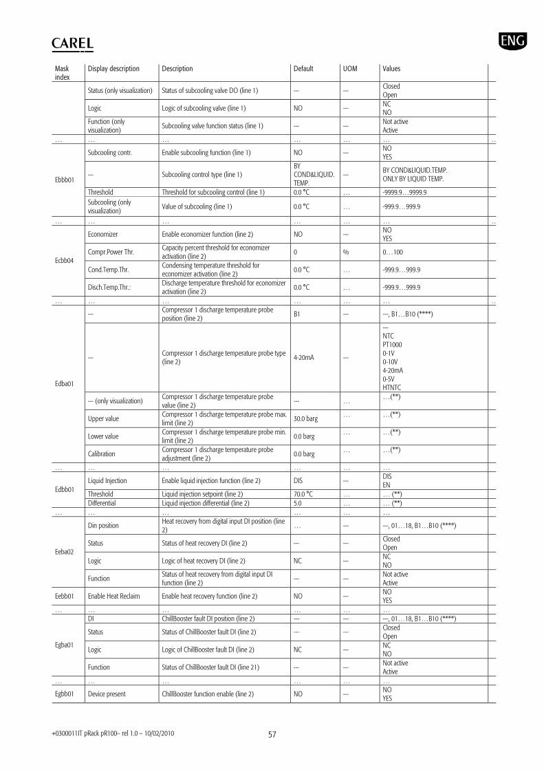
+0300011IT pRack pR100– rel 1.0 – 10/02/2010 57
Mask index
Display description Description Default UOM Values
Status (only visualization) Status of subcooling valve DO (line 1) --- --- Closed Open
Logic Logic of subcooling valve (line 1) NO --- NC NO
Function (only visualization)
Subcooling valve function status (line 1) --- --- Not active Active
… … … … … … …
Subcooling contr. Enable subcooling function (line 1) NO --- NO YES
--- Subcooling control type (line 1) BY COND&LIQUID.TEMP.
--- BY COND&LIQUID.TEMP. ONLY BY LIQUID TEMP.
Threshold Threshold for subcooling control (line 1) 0.0 °C … -9999.9…9999.9
Ebbb01
Subcooling (only visualization)
Value of subcooling (line 1) 0.0 °C … -999.9…999.9
… … … … … … …
Economizer Enable economizer function (line 2) NO --- NO YES
Compr.Power Thr. Capacity percent threshold for economizer activation (line 2)
0 % 0…100
Cond.Temp.Thr. Condensing temperature threshold for economizer activation (line 2) 0.0 °C … -999.9…999.9
Ecbb04
Disch.Temp.Thr.: Discharge temperature threshold for economizer activation (line 2)
0.0 °C … -999.9…999.9
… … … … … … …
--- Compressor 1 discharge temperature probe position (line 2)
B1 --- ---, B1…B10 (****)
--- Compressor 1 discharge temperature probe type (line 2) 4-20mA ---
--- NTC PT1000 0-1V 0-10V 4-20mA 0-5V HTNTC
--- (only visualization) Compressor 1 discharge temperature probe value (line 2)
--- … …(**)
Upper value Compressor 1 discharge temperature probe max. limit (line 2)
30.0 barg … …(**)
Lower value Compressor 1 discharge temperature probe min. limit (line 2) 0.0 barg … …(**)
Edba01
Calibration Compressor 1 discharge temperature probe adjustment (line 2)
0.0 barg … …(**)
… … … … … …
Liquid Injection Enable liquid injection function (line 2) DIS --- DIS EN
Threshold Liquid injection setpoint (line 2) 70.0 °C … … (**) Edbb01
Differential Liquid injection differential (line 2) 5.0 … … (**) … … … … … …
Din position Heat recovery from digital input DI position (line 2) … --- ---, 01…18, B1…B10 (****)
Status Status of heat recovery DI (line 2) --- --- Closed Open
Logic Logic of heat recovery DI (line 2) NC --- NC NO
Eeba02
Function Status of heat recovery from digital input DI function (line 2) --- --- Not active
Active
Eebb01 Enable Heat Reclaim Enable heat recovery function (line 2) NO --- NO YES
… … … … … … DI ChillBooster fault DI position (line 2) --- --- ---, 01…18, B1…B10 (****)
Status Status of ChillBooster fault DI (line 2) --- --- Closed Open
Logic Logic of ChillBooster fault DI (line 2) NC --- NC NO
Egba01
Function Status of ChillBooster fault DI (line 21) --- --- Not active Active
… … … … … …
Egbb01 Device present ChillBooster function enable (line 2) NO --- NO YES
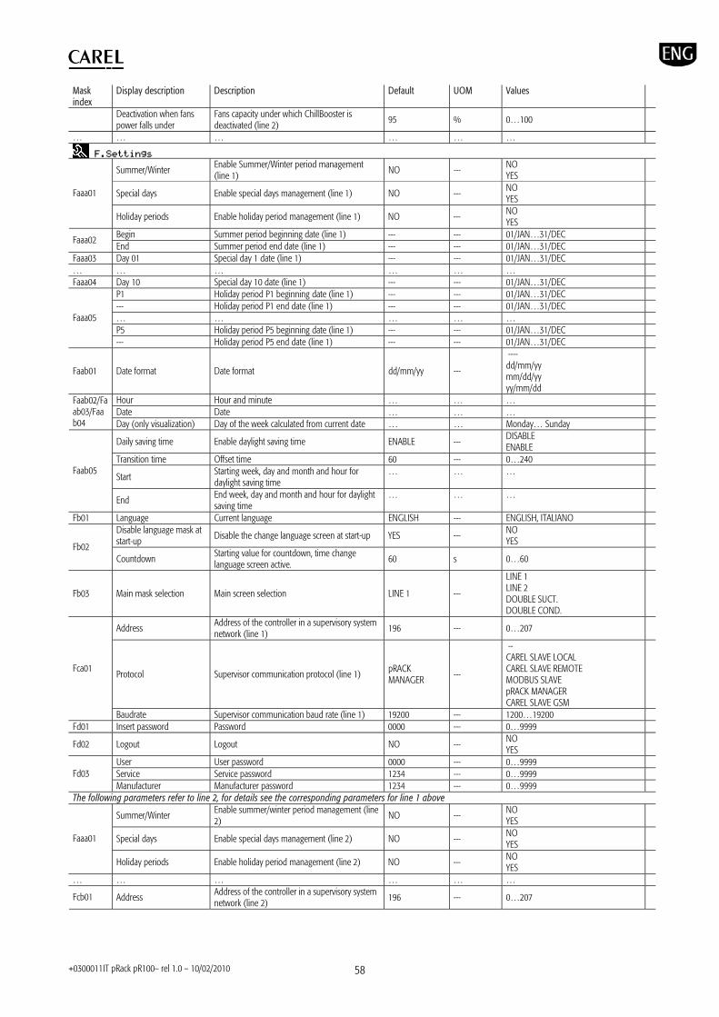
+0300011IT pRack pR100– rel 1.0 – 10/02/2010 58
Mask index
Display description Description Default UOM Values
Deactivation when fans power falls under
Fans capacity under which ChillBooster is deactivated (line 2)
95 % 0…100
… … … … … …
Summer/Winter Enable Summer/Winter period management (line 1)
NO --- NO YES
Special days Enable special days management (line 1) NO --- NO YES
Faaa01
Holiday periods Enable holiday period management (line 1) NO --- NO YES
Begin Summer period beginning date (line 1) --- --- 01/JAN…31/DEC Faaa02 End Summer period end date (line 1) --- --- 01/JAN…31/DEC
Faaa03 Day 01 Special day 1 date (line 1) --- --- 01/JAN…31/DEC … … … … … … Faaa04 Day 10 Special day 10 date (line 1) --- --- 01/JAN…31/DEC
P1 Holiday period P1 beginning date (line 1) --- --- 01/JAN…31/DEC --- Holiday period P1 end date (line 1) --- --- 01/JAN…31/DEC … … … … … P5 Holiday period P5 beginning date (line 1) --- --- 01/JAN…31/DEC
Faaa05
--- Holiday period P5 end date (line 1) --- --- 01/JAN…31/DEC
Faab01 Date format Date format dd/mm/yy ---
---- dd/mm/yy mm/dd/yy yy/mm/dd
Hour Hour and minute … … … Date Date … … …
Faab02/Faab03/Faab04 Day (only visualization) Day of the week calculated from current date … … Monday… Sunday
Daily saving time Enable daylight saving time ENABLE --- DISABLE ENABLE
Transition time Offset time 60 --- 0…240
Start Starting week, day and month and hour for daylight saving time
… … … Faab05
End End week, day and month and hour for daylight saving time
… … …
Fb01 Language Current language ENGLISH --- ENGLISH, ITALIANO Disable language mask at start-up
Disable the change language screen at start-up YES --- NO YES Fb02
Countdown Starting value for countdown, time change language screen active. 60 s 0…60
Fb03 Main mask selection Main screen selection LINE 1 ---
LINE 1 LINE 2 DOUBLE SUCT. DOUBLE COND.
Address Address of the controller in a supervisory system network (line 1)
196 --- 0…207
Protocol Supervisor communication protocol (line 1) pRACK MANAGER
---
-- CAREL SLAVE LOCAL CAREL SLAVE REMOTE MODBUS SLAVE pRACK MANAGER CAREL SLAVE GSM
Fca01
Baudrate Supervisor communication baud rate (line 1) 19200 --- 1200…19200 Fd01 Insert password Password 0000 --- 0…9999
Fd02 Logout Logout NO --- NO YES
User User password 0000 --- 0…9999 Service Service password 1234 --- 0…9999 Fd03 Manufacturer Manufacturer password 1234 --- 0…9999
The following parameters refer to line 2, for details see the corresponding parameters for line 1 above
Summer/Winter Enable summer/winter period management (line 2)
NO --- NO YES
Special days Enable special days management (line 2) NO --- NO YES
Faaa01
Holiday periods Enable holiday period management (line 2) NO --- NO YES
… … … … … …
Fcb01 Address Address of the controller in a supervisory system network (line 2)
196 --- 0…207
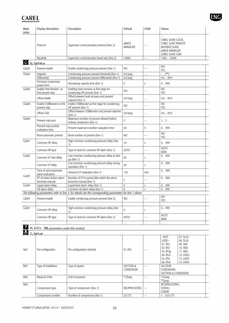
+0300011IT pRack pR100– rel 1.0 – 10/02/2010 59
Mask index
Display description Description Default UOM Values
Protocol Supervisor communication protocol (line 2) pRACK MANAGER
---
-- CAREL SLAVE LOCAL CAREL SLAVE REMOTE MODBUS SLAVE pRACK MANAGER CAREL SLAVE GSM
Baudrate Supervisor communication baud rate (line 2) 19200 --- 1200…19200
Gba01 Prevent enable Enable condensing pressure prevent (line 1) NO --- NO YES
Setpoint Condensing pressure prevent threshold (line 1) 0.0 barg … … (**) Differential Condensing pressure prevent differential (line 1) 0.0 barg … 0.0…99.9
Gba02
Decrease compressor power time
Decreasing capacity time (line 1) 0 s 0…999
Enable Heat Reclaim as first prevent step
Enabling heat recovery as first stage for condensing HP prevent (line 1)
NO --- NO YES
Gba03
Offset HeatR. Offset between heat recovery and prevent setpoint (line 1) 0.0 barg … 0.0…99.9
Enable ChillBooster as first prevent step
Enable ChillBooster as first stage for condensing HP prevent (line 1)
NO --- NO YES
Gba04
Offset Chill. Offset between ChillBooster and prevent setpoint (line 1)
0.0 barg … 0.0…99.9
Prevent max.num Maximum number of prevent allowed before locking compressor (line 1) 3 --- 1…5
Prevent max.number evaluation time
Prevent maximum number evaluation time 60 h 0…999
Gba05
Reset automatic prevent Reset number of prevent (line 1) NO --- NO YES
Common HP delay High common condensing pressure delay (line 1) 10 s 0…999 Gca01
Common HP type Type of reset for common HP alarm (line 1) AUTO --- AUTO MAN
Common LP start delay Low common condensing pressure delay at start up (line 1)
60 s 0…999 Gca02
Common LP delay Low common condensing pressure delay during operation (line 1) 20 s 0…999
Time of semi-automatic alarm evaluation
Period of LP evaluation (line 1) 120 min 0…999
Gca03 N° of retries before alarm becomes manual
Number of LP in period after which the alarm becomes manual (line 1)
5 --- 0…999
Liquid alarm delay Liquid level alarm delay (line 1) 0 s 0…999 Gca04 Oil alarm delay Common oil alarm delay (line 1) 0 s 0…999
The following parameters refer to line 2, for details see the corresponding parameters for line 1 above
Gbb01 Prevent enable Enable condensing pressure prevent (line 2) NO --- NO YES
… … … … … …
Common HP delay High common condensing pressure delay (line 2) 0 s 0…999 Gcb01
Common HP type Type of reset for common HP alarm (line 2) AUTO --- AUTO MAN
… … … … … …
o parameters under this section)
Ia01 Pre-configuration Pre-configuration selected 01. RS2 ---
--NOT USED— 01. RS2 02. RS3 03. RS3p 04. RS3i 05. RS4 06. RS4i
07. SL3d 08. SL5d 09. SW1 10. SW2 11. SW3 12. d-RS2 13. d-RS3 14. d-RS4
Ib01 Type of Installation Type of system SUCTION & CONDENSER
--- SUCTION CONDENSER SUCTION & CONDENSER
Ib02 Measure Units Unit of measure °C/barg --- °C/barg °F/psig
Compressors type Type of compressors (line 1) RECIPROCATING --- RECIPROCATING SCROLL SCREW
Ib03
Compressors number Number of compressors (line 1) 2/3 (*) --- 1…6/12 (*)

+0300011IT pRack pR100– rel 1.0 – 10/02/2010 60
Mask index
Display description Description Default UOM Values
Ib04 Number of alarms for each compressor
Number of alarms for each compressor (line 1) 1 --- 0…4/7 (*)
Ib05
Modulate speed device Modulating speed device for first compressor (line 1) NONE ---
NONE INVERTER ---/DIGITAL SCROLL (*) ---/STEPLESS (*)
Ib30 Compressors sizes Compressors sizes (line 1)
SAME CAPACITY & SAME STAGE CONF.
--- SAME CAPACITY & SAME STAGE CONF. SAME CAPACITY & DIFF. STAGE CONF. DEFINE SIZES
S1 Enable size and size for compressor group 1 (line 1)
YES 10.0
--- kW
NO/YES. 0.0…500.0
… … … … … Ib34
S4 Enable size and size for compressor group 4 (line 1)
NO ---
--- kW
NO/YES. 0.0…500.0
S1 Enable stages and stages for compressor group 1 (line 1)
YES 100
--- %
NO/YES. 100; 50/100; 50/75/100; 25/50/75/100; 33/66/100
… … … … … Ib35
S4 Enable stages and stages for compressor group 4 (line 1))
NO ---
--- kW
NO/YES. S1…S4
C01 Size group for compressor 1 (line 1) or presence of inverter
S1 --- S1…S4/INV
… … … … … Ib36
C12 Size group for compressor 12 (line 1) S1 --- S1…S4
Compr.Manufacturer Compressor manufacturer for screw compressors GENERIC ---
GENERIC BITZER REFCOMP HANBELL
Ib10
Compressor series Compressor series …(***) --- …(***)
Ib11 Compressors sizes Compressor sizes (line 1) SAME CAPACITY --- SAME CAPACITY DEFINE SIZES
S1 Enable size and size for compressor group 1 (line 1)
YES 10.0
--- kW
NO/YES. 0.0…500.0
… … … … … Ib16
S4 Enable size and size for compressor group 4 (line 1)
NO ---
--- kW
NO/YES. 0.0…500.0
C01 Size group for compressor 1 (line 1) or presence of inverter S1 --- S1…S4/INV
… … … … …
Ib17
C06 Size group for compressor 12 (line 1) --- --- S1…S4
Ib20 Compressors sizes Compressors sizes (line 1) SAME CAPACITY --- SAME CAPACITY DEFINE
S1 Enable size and size for compressor group 1 (line 1)
YES 10.0
--- kW
NO/YES. 0.0…500.0
… … … … … Ib21
S4 Enable size and size for compressor group 4 (line 1)
NO ---
--- kW
NO/YES. 0.0…500.0
C01 Size group for compressor 1 (line 1) or presence of inverter
S1 --- S1…S4/INV
… … … … … Ib22
C12 Size group for compressor 6 (line 1) S1 --- S1…S4
Regulation by Compressor control by temperature or pressure (line 1)
PRESSURE --- PRESSURE TEMPERATURE
Measure unit Unit of measure (line 1) barg --- …
Ib40
Refrigerant Type of refrigerant (suction Line 1) R404A ---
R22 R134a R404A R407C R410A R507A R290 R600
R600a R717 R744 R728 R1270 R417A R422D
Regulation type Compressor control type (line 1) DEAD ZONE --- PROPORTIONAL BAND DEAD ZONE Ib41
Enable integral time action Enable integral time for proportional suction line control (line 1)
NO --- NO YES
Setpoint Setpoint without compensation (suction line 1) 3.5 barg …(**) …(**) Ib42 Differential Differential (suction line 1) 0.3 barg …(**) …(**)
Ib43 Configure another suction line? Second suction line configuration NO --- NO
YES
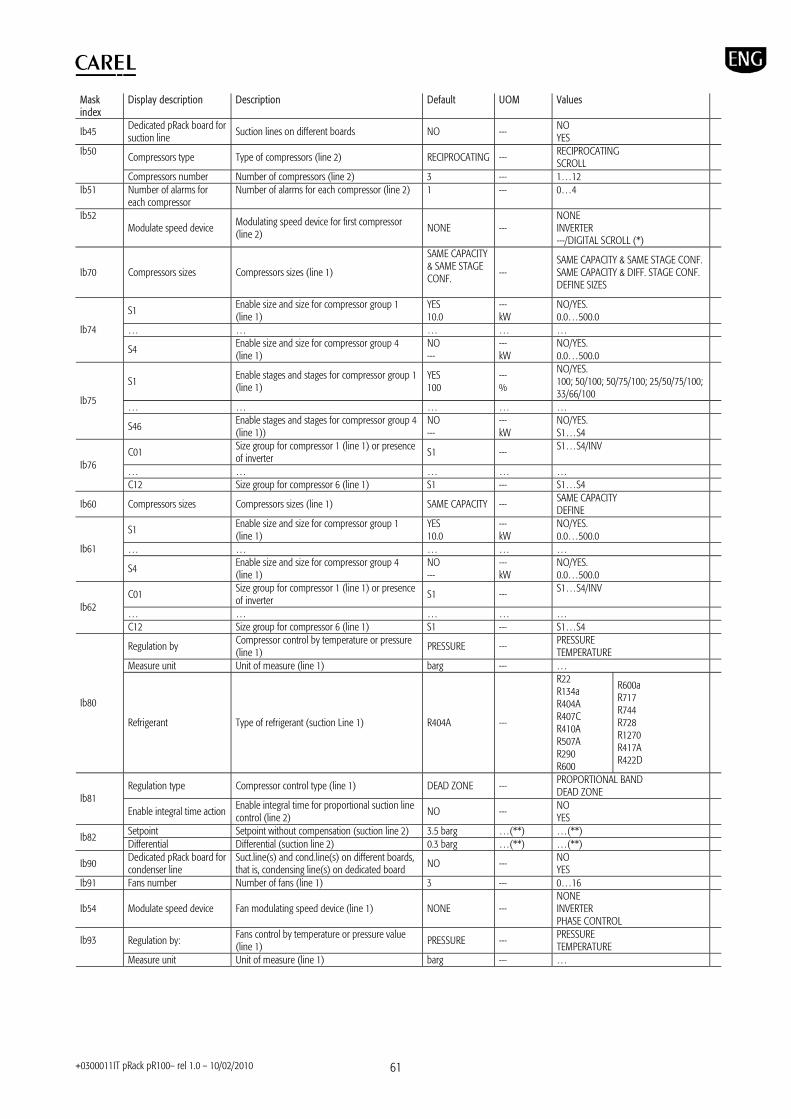
+0300011IT pRack pR100– rel 1.0 – 10/02/2010 61
Mask index
Display description Description Default UOM Values
Ib45 Dedicated pRack board for suction line
Suction lines on different boards NO --- NO YES
Compressors type Type of compressors (line 2) RECIPROCATING --- RECIPROCATING SCROLL
Ib50
Compressors number Number of compressors (line 2) 3 --- 1…12 Ib51 Number of alarms for
each compressor Number of alarms for each compressor (line 2) 1 --- 0…4
Ib52 Modulate speed device Modulating speed device for first compressor
(line 2) NONE ---
NONE INVERTER ---/DIGITAL SCROLL (*)
Ib70 Compressors sizes Compressors sizes (line 1)
SAME CAPACITY & SAME STAGE CONF.
--- SAME CAPACITY & SAME STAGE CONF. SAME CAPACITY & DIFF. STAGE CONF. DEFINE SIZES
S1 Enable size and size for compressor group 1 (line 1)
YES 10.0
--- kW
NO/YES. 0.0…500.0
… … … … … Ib74
S4 Enable size and size for compressor group 4 (line 1)
NO ---
--- kW
NO/YES. 0.0…500.0
S1 Enable stages and stages for compressor group 1 (line 1)
YES 100
--- %
NO/YES. 100; 50/100; 50/75/100; 25/50/75/100; 33/66/100
… … … … … Ib75
S46 Enable stages and stages for compressor group 4 (line 1))
NO ---
--- kW
NO/YES. S1…S4
C01 Size group for compressor 1 (line 1) or presence of inverter S1 --- S1…S4/INV
… … … … …
Ib76
C12 Size group for compressor 6 (line 1) S1 --- S1…S4
Ib60 Compressors sizes Compressors sizes (line 1) SAME CAPACITY --- SAME CAPACITY DEFINE
S1 Enable size and size for compressor group 1 (line 1)
YES 10.0
--- kW
NO/YES. 0.0…500.0
… … … … … Ib61
S4 Enable size and size for compressor group 4 (line 1)
NO ---
--- kW
NO/YES. 0.0…500.0
C01 Size group for compressor 1 (line 1) or presence of inverter
S1 --- S1…S4/INV
… … … … … Ib62
C12 Size group for compressor 6 (line 1) S1 --- S1…S4
Regulation by Compressor control by temperature or pressure (line 1)
PRESSURE --- PRESSURE TEMPERATURE
Measure unit Unit of measure (line 1) barg --- …
Ib80
Refrigerant Type of refrigerant (suction Line 1) R404A ---
R22 R134a R404A R407C R410A R507A R290 R600
R600a R717 R744 R728 R1270 R417A R422D
Regulation type Compressor control type (line 1) DEAD ZONE --- PROPORTIONAL BAND DEAD ZONE Ib81
Enable integral time action Enable integral time for proportional suction line control (line 2)
NO --- NO YES
Setpoint Setpoint without compensation (suction line 2) 3.5 barg …(**) …(**) Ib82 Differential Differential (suction line 2) 0.3 barg …(**) …(**)
Ib90 Dedicated pRack board for condenser line
Suct.line(s) and cond.line(s) on different boards, that is, condensing line(s) on dedicated board NO --- NO
YES
Ib91 Fans number Number of fans (line 1) 3 --- 0…16
Ib54 Modulate speed device Fan modulating speed device (line 1) NONE --- NONE INVERTER PHASE CONTROL
Regulation by: Fans control by temperature or pressure value (line 1) PRESSURE --- PRESSURE
TEMPERATURE Ib93
Measure unit Unit of measure (line 1) barg --- …

+0300011IT pRack pR100– rel 1.0 – 10/02/2010 62
Mask index
Display description Description Default UOM Values
Refrigerant Type of refrigerant (condensing line 1) R404A ---
R22 R134a R404A R407C R410A R507A R290 R600
R600a R717 R744 R728 R1270 R417A R422D
Regulation type Fan control type (line 1) PROPORTIONAL BAND --- PROPORTIONAL BAND
DEAD ZONE Ib94
Enable integral time action Enable integral time for proportional band control
NO --- NO YES
Setpoint Setpoint without compensation (condensing line 1)
12.0 barg …(**) …(**) Ib95 Differential Differential (condensing line 1) 2.0 barg …(**) …(**)
Ib96 Configure another condensing line? Second condensing line configuration NO --- NO
YES
Ib1a Fans number Number of fans (line 2) 3 --- 0…16 … … … … … … Ib1e Differential Differential (condensing line 2) 2.0 barg …(**) …(**) Ic01 Type of Installation Type of plant SUCTION &
CONDENSER --- SUCTION
CONDENSER SUCTION & CONDENSER
Ic02 Measure Units Unit of measure °C/barg --- °C/barg °F/psig
Ic03 Number of suction lines Number of suction lines 1 --- 0…2
Ic04 Dedicated pRack board for suction line
Suction lines are on different boards NO --- NO YES
Compressors type Type of compressors (line 1) RECIPROCATING --- RECIPROCATING SCROLL SCREW
Ic05
Compressors number Number of compressors (line 1) 4 --- 1…6/12 (*)
Compressors type Type of compressors (line 2) RECIPROCATING --- RECIPROCATING SCROLL SCREW
Ic06
Compressors number Number of compressors (line 2) 0 --- 1…6 Ic07 Number of condensing
line Number of condensing lines in the system 1 --- 0…2
Line1 Number of fans (line 1) 4 --- 0…16 Ic08 Line2 Number of fans (line 2) 0 --- 0…16
Ic09 Dedicated pRack board for condenser line
Condenser lines are on different boards NO --- NO YES
Save configuration Save Manufacturer configuration NO --- NO YES
Id01 Load configuration Manual installation of Manufacturer configuration NO --- NO
YES
Id02 Restore default Manual installation of Carel default values NO --- NO YES
(*) Depending on the type of compressor (**)Depending on the unit of measure selected (***)Depending on the compressor manufacturer (****)Depending on the hardware size

+0300011IT pRack pR100– rel 1.0 – 10/02/2010 63
8. ALARMS pRack PR100 can manage both alarms relating to the status of the digital inputs and to operation of the system. For each alarm, the following are controlled:
The actions on the devices, if necessary The output relays (one global and two with different priorities, if
configured) The red LED on the terminal and the buzzer, where present The type of acknowledgement (automatic, manual, semiautomatic) Any activation delay
The complete list of alarms, with the related information as described above, is available in Appendix A.4.
8.1 Alarm management All alarms feature the following behaviour:
When an alarm is activated, the red LED flashes and the buzzer is activated (where present); the output relays corresponding to the global alarm and to any alarms with priority are activated (if configured)
Pressing the (Alarm) button, the red LED stays on steady, the buzzer is muted and the alarm screen is shown
If there is more than one active alarm, these can be scrolled using
(Up) (Down). This condition is signalled by an arrow at the bottom right of the screen
Pressing the (Alarm) button again for at least 3 seconds acknowledges the alarms manually, and these are cleared from the display unless others are active (they are saved in the log)
8.1.1 Priority For certain alarms, the alarm output relay can be set with two types of priority:
R1: serious alarm R2: normal alarm
The corresponding relays, once configured, are activated when an alarm with the corresponding priority occurs. For the other alarms, the priority is fixed and is associated by default with one of the two relays.
8.1.2 Acknowledgement The alarms can have manual, automatic or semiautomatic acknowledgement:
Manual: the alarm is acknowledged by pressing the (Alarm) button twice, the first time displays the corresponding alarm screen and mutes the buzzer, the second (extended, for at least 3 seconds) cancels the alarm (which is saved in the log). If the alarm is still active, acknowledgement has no effect and the signal is shown again.
Automatic: when the alarm condition ceases, the alarm is automatically reset, the LED comes on steady and the
corresponding screen remains displayed until the (Alarm) button is pressed and held; the alarm is saved in the log.
Semiautomatic: acknowledgement is automatic, until a maximum number of activations in set time. If the number reaches the maximum set, acknowledgement becomes manual.
8.1.3 Log The alarm log can be accessed:
from branch G.a of the main menu
by pressing the (Alarm) button and then (Enter) when there are no active alarms
by pressing (Enter) after having scrolled all the alarms. The alarm log screens show:
1. Order of activation (no. 01 is the oldest alarm) 2. Hour and date the alarm was activated 3. Short description 4. Main values recorded at the moment the alarm was activated
(suction pressure and condensing pressure)
Note: A maximum of 50 alarms can be logged; after this limit any new events overwrite the oldest ones, which are therefore deleted.
8.2 Compressor alarms The number of alarms for each compressor can be set during the configuration phase using the Wizard or subsequently from branch C.a.e/C.b.e of the main menu. The number is the same for all the compressors on the same line.
Fig. 8.a
Note: The maximum number of alarms that can be configured for each compressor depends not only on the type of compressor, but also on the size of pRack and the number of compressors fitted. After having selected the number of alarms (maximum 4 for the reciprocating or scroll compressors and 7 for screw compressors), the settings can be configured for each alarm, choosing a description from the options shown in the table, the output relay, the type of reset, delay and priority. The effect of the alarm on the devices is set and involves stopping the compressor, except for the oil warning. Possible descriptions for compressor alarms
Reciprocating or scroll Screw Generic Generic Overload Overload High pressure High pressure Low pressure Low pressure Oil Oil Screw rotation Oil warning (Filter Blocked)
An example of a screen for selecting the description of the alarm is shown in the figure:
Fig. 8.b After having selected the ‘generic’ description, no other description can be selected. In general, the descriptions are divided into four groups:
generic others (overload, oil, high pressure , low pressure) screw rotation oil warning
After a description has been selected for a certain group, descriptions from a different group can not be selected for that alarm. For example, generic only, or overload + oil, or rotation only or overload + high pressure., etc. can be selected.

+0300011IT pRack pR100– rel 1.0 – 10/02/2010 64
Each alarm will have one alarm screen, which will show all the descriptions associated to that alarm. Based on the number of alarms selected, the descriptions associated by default are shown in the table below Default descriptions based on the number of alarms
Number of alarms Descriptions 1 Generic
Overload 2 HP-LP Overload HP-LP 3 Oil Overload HP LP
4
Oil Overload HP LP Oil
5
Oil warning Overload HP LP Oil Oil warning
6
Rotation Overload HP LP Oil Oil warning Rotation
7
Generic
Note: for oil alarms, special management is available whereby the alarm is interpreted as an oil level alarm. When the alarm is activated, a number of attempts are made to restore the level for a set time before the alarm is signalled and the compressor stopped; see paragraph 6.6.1 for details. If a modulating device is used for the compressors, further alarms become available: compressor inverter warning, common for the entire suction line,
when the device is an inverter oil sump temperature alarm, high discharge temperature and oil
dilution, for Digital Scroll compressors For each compressor, two alarm variables are sent to the supervisor, one for each priority. As well as the alarm signal, the description of the alarm is also sent to the supervisor, using the values shown in the table: Description of alarms sent to the supervisor
Description value Meaning 1 Generic 2 Overload 4 High pressure 6 Overload + high pressure 8 Low pressure 10 Overload + low pressure 16 Oil 18 Overload + oil 20 High pressure + oil 22 Overload + high pressure + oil 24 Low pressure + oil 26 Overload + low pressure + oil 32 Rotation (screw compressors only) 64 Oil warning (screw compressors only)
8.3 Pressure and prevent alarms pRack PR100 can manage pressure alarms from a pressure switch or probe, according to the following diagram. Alarms from pressure switch:
Low suction pressure High condensing pressure
Alarms from probe: Low suction pressure High suction pressure Low condensing pressure High condensing pressure
One possible example for the low pressure alarms is shown in the figure:
Fig. 8.c
In addition, the high pressure alarm features a prevent function, also available using additional functions, such as heat recovery and ChillBooster.
8.3.1 Pressure alarms from pressure switch The parameters corresponding to these alarms can be set in branch G.c.a/G.c.b of the main menu. Low suction pressure from pressure switch This alarm features semiautomatic reset, and both the monitoring time and the number of activations in the specified period can be set. If the number of activations is higher, reset becomes manual. In addition, the delay after which the alarm is activated on both start-up and during operation can be set. The delay at start-up only applies to unit start-up and not compressor power-up. The low suction pressure alarm from pressure switch has the effect of stopping all the compressors, ignoring the times. High condensing pressure from pressure switch This alarm features manual or automatic reset, as configured by the user. The delay after which the alarm is activated can also be set. The high condensing pressure alarm from pressure switch has the effect of stopping all the compressors, ignoring the times and forcing the fans on at maximum speed.
8.3.2 Pressure alarms from probe The parameters corresponding to these alarms can be set in branch C.a.e/C.b.e of the main menu for the suction pressure and D.a.e/D.b.e for the condensing pressure. For these types of alarms, reset is automatic and the activation threshold and differential can be set, as well as the type of threshold, which may be absolute or relative to the control set point. The figure shows an example of setting the threshold to relative.
Fig. 8.d
Low suction pressure from probe
Setpoint
Differential
Relative threshold Pressure
HP
Alarm
Pressure switch l
Differential
Probe alarm
Pressure
LP

+0300011IT pRack pR100– rel 1.0 – 10/02/2010 65
The low suction pressure alarm from probe has the effect of stopping all the compressors, ignoring the times. High suction pressure from probe The high suction pressure alarm from probe has the effect of forcing all the compressors on, ignoring the control times, but observing the compressor protection times. Low condensing pressure from probe The low condensing pressure alarm from probe has the effect of stopping all the fans, ignoring the times. High condensing pressure from probe The high condensing pressure alarm from probe has the effect of forcing all the fans on and stopping all the compressors, ignoring the times.
8.3.3 High pressure prevention pRack PR100 can manage 3 types of high condensing pressure prevention actions, involving:
overriding the compressors and fans activating heat recovery activating ChillBooster
Prevent by overriding the compressors and fans The parameters relating to this function can be set in branch G.b.a/G.b.b of the main menu. The effect of this type of prevent action is to force all the fans on and switch all the compressors off (except the minimum capacity stage), ignoring the control times but observing the compressor protection times. As well as the activation threshold, which is always absolute, and the activation differential, a compressor deactivation time can be set, corresponding to the time needed to switch off all the compressors, except for the minimum capacity stage. In addition, both the monitoring time and the number of activations in the specified period can be set. If the number of activations is higher, reset becomes manual. Prevent by activating heat recovery The parameters relating to this function can be set in branch G.b.a/G.b.b of the main menu, if the heat recovery function is present. As well as enabling the function, an offset from the activation threshold for the prevent by overriding devices function must be set. The activation differential for this function is the same as set for the prevent by overriding devices function. When reaching the threshold, pRack PR100 activates the heat recovery function, if the conditions allow; see paragraph 6.6.3 for details. Prevent by activating ChillBooster The parameters relating to this function can be set in branch G.b.a/G.b.b of the main menu, if the ChillBooster function is present. As well as enabling the function, an offset from the activation threshold for the prevent by overriding devices function must be set. The activation differential for this function is the same as set for the prevent by overriding devices function. When reaching the threshold, pRack PR100 force activates the ChillBooster, if the conditions allow; see paragraph 6.6.5 for details. The following figure illustrates the activation thresholds for the prevent function and the safety devices:
Fig. 8.e
Prevent
HP by pressure switch
Offset
HP by probe
Heat recovery or ChillBooster
Pressure
Time

+0300011IT pRack pR100– rel 1.0 – 10/02/2010 66
9. SUPERVISORY AND COMMISSIONING SYSTEMS pRack pR100 can be connected to various supervisory systems, specifically the Carel and Modbus communication protocols can be used. For the Carel protocol, the PlantVisor PRO and PlantWatch PRO models are available. In addition, pRack pR100 can be connected to the pRack Manager commissioning software. 9.1.1 PlantVisor PRO and PlantWatch PRO supervisory systems Connection to Carel PlantVisor PRO and PlantWatch PRO supervisor systems uses the RS485 card already fitted on some models of pRack pR100. For details on the models of card available, see Chapter 1.
Note: In general, the pRack boards that manage the suction lines must be fitted with the supervisor connection card, consequently boards with pLAN address 1 or 2. Three different models of PlantVisor PRO and PlantWatch PRO are available, used to supervise system configurations with one or two lines:
L1 – one line: can be used for system configurations with just one suction and/or condenser line.
L2 – one line: can be used for system configurations with two suction and/or condenser lines, and the two suction lines are managed by separate boards.
Two lines: can be used for system configurations with two suction and/or condenser lines, and the two suction lines are managed by the same board.
Important: model L2 – One line must be used only in association with model L1 – One line. For supervision of system configurations with just one line only model L1 – One line can be used. Some examples of using PlantVisor PRO and PlantWatch PRO are illustrated in the figure below.
Fig. 9.a
The complete list of supervisor variables, with the corresponding addresses and descriptions, can be supplied upon request.
9.1.2 Commissioning software pRack Manager is configuration and real-time monitoring software used to check the operation of pRack pR100, for commissioning, debug and maintenance operations. The software is available on the internet at http://ksa.CAREL.com in the section “download support software utilities”.The installation includes, in addition to the program, the user manual and the necessary drivers. pRack Manager can be used to set the configuration parameters, modify the values of volatile and permanent variables, save graphs of the main system values to file, manually manage the unit I/Os using simulation files and monitor/reset alarms on the unit where the device is installed. pRack pR100 is able to virtualise all the inputs and outputs, both digital and analogue, therefore each input and output can be overridden by pRack Manager. pRack Manager manages <file name>.DEV files that contain the user parameter configurations and that can be downloaded from the pRack pR100 board and then subsequently uploaded. To use the pRack Manager program, a serial converter output RS485 with CVSTDUTLF0 (telephone connector) or CVSTDUMOR0 (3 pin terminal) must be connected to the board. The connection to pRack Manager can be made:
1. Via the RS485 serial port used for the “pLAN” connection 2. Via the BMS serial port with RS485 serial card and activating the
pRack Manager protocol by parameter on screen Fca01 or connecting pRack Manager and selecting SearchDevice = Auto (BMS or FB) on the “Connection settings” tab. In this case, the connection is established after around 15-20 seconds.
The following figure shows an example of connection to the PC via the RS485 serial port used for the “pLAN” connection
Fig. 9.b
Note: for further details see the pRack Manager program online help.

+0300011IT pRack pR100– rel 1.0 – 10/02/2010 67
10. UPDATING THE SOFTWARE The pRack PR100 boards are supplied with the software already loaded. If an update is required, the following can be used:
pRack Manager SmartKey programming key
10.1.1 Updating using pRack Manager The software resident in the pRack pR100 boards can be updated from a PC. For the connection procedure see Chapter 9, while for further details see the pRack Manager program online help.
Note: The pRack PR100 software is protected by digital signature and cannot be loaded onto hardware other than pRack PR100 (e.g. pCO3), otherwise after 5 minutes of operation the software locks up, all the relays open and the warning “INVALID OEM IDENTIFIER” is shown.
Note: The pCOLoad program can also be used to update the pRack pR100 software, however Winload cannot be used. 10.1.2 Updating using SmartKey The SMARTKEY programming key can copy the contents of one pRack pR100 board to another identical board, using the telephone connector on the terminal (the pLAN must be disconnected). From a PC, with the SmartKey Programmer software running, the key can be configured to perform specific operations: acquire log files, program applications, etc. The SmartKey Programmer software is installed together with pRack Manager. The following figure shows the connection of the SmartKey to the PC using the PCOSO0AKY0 converter.
Fig. 10.a
Note: for further details on using the SmartKey, see the corresponding instruction sheet. For details on the SmartKey Programmer see the online manual. 10.1.3 Saving parameters between different software versions The configuration parameters can be saved and loaded after having updated the software, using the following procedure (for details see the pRack Manager online manual):
1. Connect pRack Manager 2. From Commissioning/Settings select the .2cf file relating to the
current version on pRack PR100, e.g. 1.0 3. From Device Configuration, read all the variables and save them to
an .xls file (required). 4. Update the software version on pRack PR100 5. Reconnect pRack Manager 6. From Commissioning/Settings select the .2cf file relating to the new
software version on pRack PR100, e.g. 1.1 7. From Device Configuration, import the .xls file saved previously.

+0300011IT pRack pR100– rel 1.0 – 10/02/2010 68
11. APPENDIX
A.1 System configurations available The system configurations available are shown in the table:
System configurations: Configuration number
Description Suction lines
Condenser lines
Compressors L1/L2
Maximum number of compressors per line L1/L2
Units present in pLAN (in addition to the terminal)
Reference diagram
1 No suction line, one condenser line 0 1 - - 1 a 2 No suction line, two condenser lines 0 2 - - 1 a
3 1 suction line (scroll or piston compressors), no condenser line 1 0 scroll, piston 12 1 a
4 1 suction line (scroll or piston compressors), 1 condenser line 1 1 scroll, piston 12 1 a
5 1 suction line (scroll or piston compressors), 1 condenser line on a separate board 1 1 scroll, piston 12 1, 3 b
6 2 suction lines on the same board (scroll or piston compressors), no condenser line 2 0
scroll, piston/scroll, piston 12 1 c
7 2 suction lines on the same board (scroll or piston compressors), 1 condenser line 2 1
scroll, piston/scroll, piston 12 1 c
8 2 suction lines on the same board (scroll or piston compressors), 1 condenser line on a separate board 2 1
scroll, piston/scroll, piston 12 1, 3 e
9 2 suction lines (scroll or piston compressors), 2 condenser lines on the same board 2 2
scroll, piston/scroll, piston 12 1 f
10 2 suction lines on the same board (scroll or piston compressors), 2 condenser lines on separate boards 2 2
scroll, piston/scroll, piston 12 1, 3 g
11 2 suction lines on separate boards (scroll or piston compressors), 1 condenser line on suction line 1 board 2 1
scroll, piston/scroll, piston 12 1, 2 h
12 2 suction lines on separate boards (scroll or piston compressors), 1 condenser line on a separate board 2 1
scroll, piston/scroll, piston 12 1, 2 .3 d
13 2 suction lines on separate boards (scroll or piston compressors), 2 condenser lines (one for each suction line board) 2 2
scroll, piston/scroll, piston 12 1, 2 h
14 2 suction lines on separate boards (scroll or piston compressors), 2 condenser lines on separate boards 2 2
scroll, piston/scroll, piston 12 1, 2, 3, 4 i
15 1 suction line (up to 2 screw compressors), no condenser line 1 0 screw 2 1 a
16 1 suction line (up to 2 screw compressors), 1 condenser line 1 1 screw 2 1 a
17 1 suction line (up to 2 screw compressors), 1 condenser line on a separate board 1 1 screw 2 1, 3 b
18
2 suction lines on separate boards (up to 2 screw compressors on line 1 and scroll or piston compressors on line 2), 1 condenser line on suction line 1 board 2 1 screw/scroll, piston 2/ 12 1, 2 h
19
2 suction lines on separate boards (up to 2 screw compressors on line 1 and scroll or piston compressors on line 2), 1 condenser line on a separate board 2 1 screw/scroll, piston 2/ 12 1, 2, 3 d
20
2 suction lines on separate boards (up to 2 screw compressors on line 1 and scroll or piston compressors on line 2), 2 condenser lines (one for each suction line board) 2 2 screw/scroll, piston 2/ 12 1, 2 h
21
2 suction lines on separate boards (up to 2 screw compressors on line 1 and scroll or piston compressors on line 2), 2 condenser lines on separate boards 2 2 screw/scroll, piston 2/ 12 1, 2, 3, 4 i
22 1 suction line (up to 4 screw compressors), no condenser line 1 0 screw 4 1, 5 a
23 1 suction line (up to 4 screw compressors), 1 condenser line 1 1 screw 4 1, 5 a
24 1 suction line (up to 4 screw compressors), 1 condenser line on a separate board 1 1 screw 4 1, 3, 5 b

+0300011IT pRack pR100– rel 1.0 – 10/02/2010 69
25
2 suction lines on separate boards (up to 4 screw compressors on line 1 and scroll or piston compressors on line 2), 1 condenser line on suction line 1 board 2 1 screw/scroll, piston 4/ 12 1, 2, 5 h
26
2 suction lines on separate boards (up to 4 screw compressors on line 1 and scroll or piston compressors on line 2), 1 condenser line on a separate board 2 1 screw/scroll, piston
4/ 12
1, 2, 3, 5 d
27
2 suction lines on separate boards (up to 4 screw compressors on line 1 and scroll or piston compressors on line 2), 2 condenser lines (one for each suction line board) 2 2 screw/scroll, piston
4/ 12
1, 2, 5 h
28
2 suction lines on separate boards (up to 4 screw compressors on line 1 and scroll or piston compressors on line 2), 2 condenser lines on separate boards 2 2 screw/scroll, piston
4/ 12
1, 2, 3, 4, 5 i
29 1 suction line (up to 6 screw compressors), no condenser line 1 0 screw 6 1, 5, 7 a
30 1 suction line (up to 6 screw compressors), 1 condenser line 1 1 screw 6 1, 5, 7 a
31 1 suction line (up to 6 screw compressors), 1 condenser line on a separate board 1 1 screw 6 1, 3, 5, 7 b
32
2 suction lines on separate boards (up to 6 screw compressors on line 1 and scroll or piston compressors on line 2), 1 condenser line on suction line 1 board 2 1 screw/scroll, piston 6/ 12 1, 2, 5, 7 h
33
2 suction lines on separate boards (up to 6 screw compressors on line 1 and scroll or piston compressors on line 2), 1 condenser line on a separate board 2 1 screw/scroll, piston 6/ 12 1, 2, 3, 5, 7 d
34
2 suction lines on separate boards (up to 6 screw compressors on line 1 and scroll or piston compressors on line 2), 2 condenser lines (one for each suction line board) 2 2 screw/scroll, piston 6/ 12 1, 2, 5, 7 h
35
2 suction lines on separate boards (up to 6 screw compressors on line 1 and scroll or piston compressors on line 2), 2 condenser lines on separate boards 2 2 screw/scroll, piston 6/ 12
1, 2, 3, 4, 5, 7 i

+0300011IT pRack pR100– rel 1.0 – 10/02/2010 70
The system configurations available refer to the following diagrams:
Note: For screw compressors, each pRack pR100 board can manage up to two compressors, consequently in the following diagrams one board can be used for each pair of compressors. a) up to 1 suction line (scroll or piston compressors) and up to 1 condenser line on just one pRack pR100 board:
Fig. A1.a b) 1 suction line (scroll or piston compressors) and 1 condenser line on a separate board:
Fig. A1.b
c) 2 suction lines on the same board (scroll or piston compressors) and up to 1 condenser line:
Fig. A1.c
d) 2 suction lines on separate boards (up to 2 screw compressors on line 1 and scroll or piston compressors on line 2), 1 condenser line on a separate board:
Fig. A1.d e) 2 suction lines on the same board (scroll or piston compressors), 1 condenser line on a separate board:
I/O
I/O I/O
pLAN
d pLAN
I/O
I/O
a
I/O
I/O
pLAN b
I/O
I/O
I/O
c
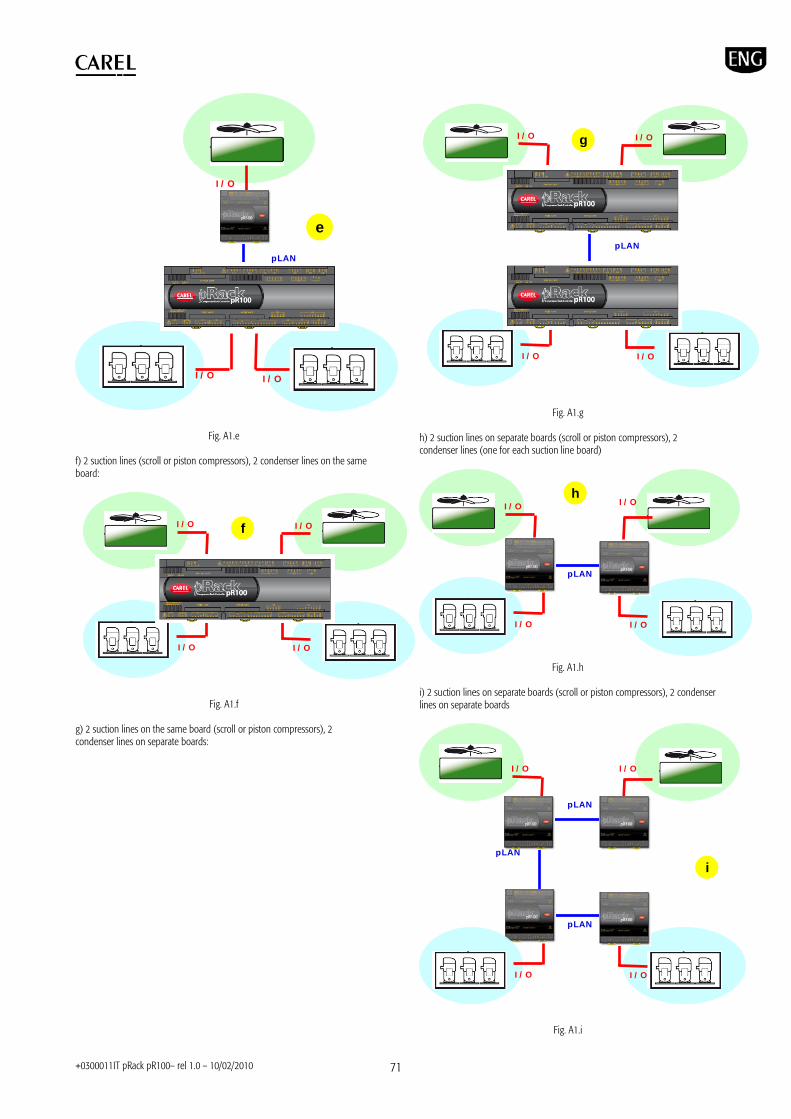
+0300011IT pRack pR100– rel 1.0 – 10/02/2010 71
Fig. A1.e f) 2 suction lines (scroll or piston compressors), 2 condenser lines on the same board:
Fig. A1.f g) 2 suction lines on the same board (scroll or piston compressors), 2 condenser lines on separate boards:
Fig. A1.g h) 2 suction lines on separate boards (scroll or piston compressors), 2 condenser lines (one for each suction line board)
Fig. A1.h
i) 2 suction lines on separate boards (scroll or piston compressors), 2 condenser lines on separate boards
Fig. A1.i
I/O
I/O I/O
pLAN
i pLAN
I/O
pLAN
I/O
I/O I/O
pLAN
h I/O
I/O
I/O
I/O
I/O
g
pLAN
I/O
I/O
I/O
e
pLAN
I/O
I/O
I/O
I/O
f

+0300011IT pRack pR100– rel 1.0 – 10/02/2010 72
A.2 System configurations with more than one pLAN board If the system configuration involves the connection of more than one board in a pLAN, the addresses must be set correct before select a solution of configuration. For the addresses to be assigned to the pRack pR100 boards see Appendix A.1. pRack pR100 can use two user terminals (as well as a built-in terminal) with addresses 31 and 32. The default user terminal address is 32, so only if a second terminal is required must the address of this be set to 31, as described below. The address of the terminal is also required when having to set the address of the pRack pR100 boards, when multiple boards are connected to the pLAN. After having correctly connected and configured the pLAN network of pRack pR100 boards, the system can be configured as described in paragraph 4.1. 11.2.1 Setting the address of the terminal The pRack pR100 user terminal is supplied with the default address 32, allowing the terminal to be used without requiring any additional operations; nonetheless, in order to use an additional terminal or configure the pLAN address of the boards, it needs to be changed according to the following procedure:
1. power the terminal via the special telephone connector;
2. press the 3 buttons, , and together for at least 5 seconds; the terminal will display a screen similar to the one below, with the cursor flashing in the top left corner:
.
Fig. A2.a
3. press once: the cursor will move to the “Display address setting” field;
4. select the desired value using and , and confirm by pressing
again; if the value selected is different from the value saved, the following screen will be displayed and the new value will be saved to the display’s permanent memory.
Fig. A2.b
Note: if the address field is set to 0, the “I/O Board address” field is no longer displayed, as it has no meaning.
Important: if the settings are not made correctly, the text and the images on the display will be displayed incorrectly and out of order.
Important: if during this operation the terminal detects inactivity of the pRack board whose output is being displayed, the display is cleared and a message similar to the one below is shown.
Fig. A2.b If the terminal detects inactivity of the entire pLAN network, that is, it does not receive any messages from the network for 10 seconds consecutively, it clears the display and shows the following message:
Fig. A2.d
11.2.2 Setting the address of the pRack pR100 board The pLAN address of the pRack boards can be set from any pGD1 terminal, using the following procedure:
1. set address 0 on the terminal (see the previous paragraph for details on how to set this address);
2. power down the pRack pR100 board; 3. disconnect any pLAN connections to other boards from the pRack pR100
board; 4. connect the terminal to the pRack pR100 board;
5. power up the pRack pR100 board, while pressing the and buttons on the terminal together. After a few seconds the pRack pR100 board begins the start-up sequence and the display shows a screen similar to the one below:
Fig. A2.e
6. when this screen is displayed, wait 10 seconds and then release the buttons;
7. the pRack pR100 board interrupts the start-up sequence and shows a configuration screen, similar to the one below:
Fig. A2.f
Then set the pLAN address using the and buttons on the terminal.
8. Confirm the address by pressing : the pRack pR100 board completes the start-up sequence and uses the set address.

+0300011IT pRack pR100– rel 1.0 – 10/02/2010 73
A.3 Example of configuring a system with 2 suction and condenser lines using the Wizard Below is a possible example of using the Wizard to configure a typical system like the one shown in the figure, with 2 suction lines and 2 condenser lines on different boards:
Fig. A3.a
The preliminary operations to be completed before configuration are as follows:
1. with the boards not connected in the pLAN, power up the second pRack board and set the pLAN address to 2 (for details see Appendix A.2)
2. power down and connect the two boards in the pLAN, plus any terminals, as described in paragraph 3.7
3. power up the boards and wait for the Wizard selection screen to be displayed
Then select the type of system as SUCTION & CONDENSER:
Fig. A3.b Set the type of compressors and control for suction line 1, answering the questions prompted by the pRack PR100 software, e.g.:
Fig. A3.c
Fig. A3.d
Fig. A3.e After having configured suction line 1, a prompt will be shown to configure another suction line, obviously the answer is YES:
Fig. A3.f To the next question, which prompts if there is a pRack board dedicated to the second line, answer YES; in this way, the pRack PR100 software prepares to configure the board with address 2 in the pLAN:
Fig. A3.g After having answered the questions for the configuration of the second suction line, the software then asks if there is a pLAN board dedicated to condenser line 1. In the case shown in the example, answer NO.
I/O
I/O I/O
pLAN
I/O

+0300011IT pRack pR100– rel 1.0 – 10/02/2010 74
Fig. A3.h After having configured condenser line 1, the software asks if condenser line 2 is used; answer YES:
Fig. A3.i After having also configured the second condenser line, the software asks if a summary should be displayed of the settings made:
Fig. A3.j If the settings are correct, the set values can be installed:
Fig. A3.k After waiting a few seconds, the unit can be started.
Fig. A3.l
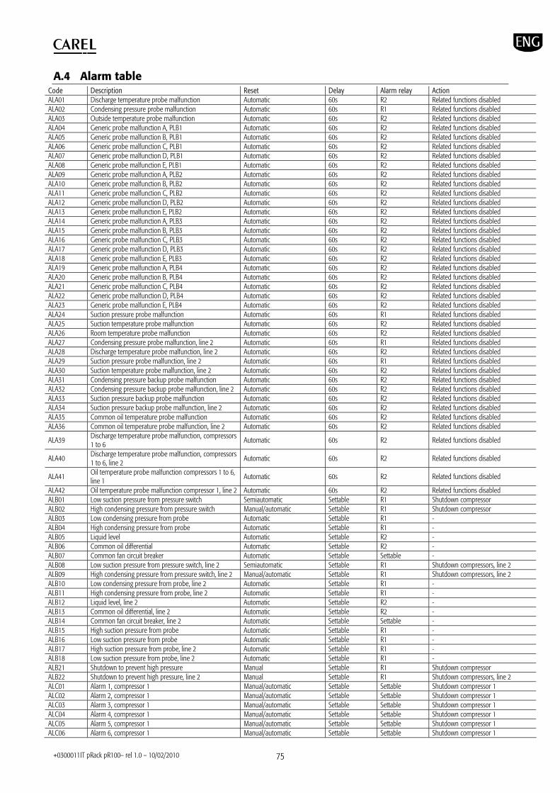
+0300011IT pRack pR100– rel 1.0 – 10/02/2010 75
A.4 Alarm table Code Description Reset Delay Alarm relay Action ALA01 Discharge temperature probe malfunction Automatic 60s R2 Related functions disabled ALA02 Condensing pressure probe malfunction Automatic 60s R1 Related functions disabled ALA03 Outside temperature probe malfunction Automatic 60s R2 Related functions disabled ALA04 Generic probe malfunction A, PLB1 Automatic 60s R2 Related functions disabled ALA05 Generic probe malfunction B, PLB1 Automatic 60s R2 Related functions disabled ALA06 Generic probe malfunction C, PLB1 Automatic 60s R2 Related functions disabled ALA07 Generic probe malfunction D, PLB1 Automatic 60s R2 Related functions disabled ALA08 Generic probe malfunction E, PLB1 Automatic 60s R2 Related functions disabled ALA09 Generic probe malfunction A, PLB2 Automatic 60s R2 Related functions disabled ALA10 Generic probe malfunction B, PLB2 Automatic 60s R2 Related functions disabled ALA11 Generic probe malfunction C, PLB2 Automatic 60s R2 Related functions disabled ALA12 Generic probe malfunction D, PLB2 Automatic 60s R2 Related functions disabled ALA13 Generic probe malfunction E, PLB2 Automatic 60s R2 Related functions disabled ALA14 Generic probe malfunction A, PLB3 Automatic 60s R2 Related functions disabled ALA15 Generic probe malfunction B, PLB3 Automatic 60s R2 Related functions disabled ALA16 Generic probe malfunction C, PLB3 Automatic 60s R2 Related functions disabled ALA17 Generic probe malfunction D, PLB3 Automatic 60s R2 Related functions disabled ALA18 Generic probe malfunction E, PLB3 Automatic 60s R2 Related functions disabled ALA19 Generic probe malfunction A, PLB4 Automatic 60s R2 Related functions disabled ALA20 Generic probe malfunction B, PLB4 Automatic 60s R2 Related functions disabled ALA21 Generic probe malfunction C, PLB4 Automatic 60s R2 Related functions disabled ALA22 Generic probe malfunction D, PLB4 Automatic 60s R2 Related functions disabled ALA23 Generic probe malfunction E, PLB4 Automatic 60s R2 Related functions disabled ALA24 Suction pressure probe malfunction Automatic 60s R1 Related functions disabled ALA25 Suction temperature probe malfunction Automatic 60s R2 Related functions disabled ALA26 Room temperature probe malfunction Automatic 60s R2 Related functions disabled ALA27 Condensing pressure probe malfunction, line 2 Automatic 60s R1 Related functions disabled ALA28 Discharge temperature probe malfunction, line 2 Automatic 60s R2 Related functions disabled ALA29 Suction pressure probe malfunction, line 2 Automatic 60s R1 Related functions disabled ALA30 Suction temperature probe malfunction, line 2 Automatic 60s R2 Related functions disabled ALA31 Condensing pressure backup probe malfunction Automatic 60s R2 Related functions disabled ALA32 Condensing pressure backup probe malfunction, line 2 Automatic 60s R2 Related functions disabled ALA33 Suction pressure backup probe malfunction Automatic 60s R2 Related functions disabled ALA34 Suction pressure backup probe malfunction, line 2 Automatic 60s R2 Related functions disabled ALA35 Common oil temperature probe malfunction Automatic 60s R2 Related functions disabled ALA36 Common oil temperature probe malfunction, line 2 Automatic 60s R2 Related functions disabled
ALA39 Discharge temperature probe malfunction, compressors 1 to 6
Automatic 60s R2 Related functions disabled
ALA40 Discharge temperature probe malfunction, compressors 1 to 6, line 2
Automatic 60s R2 Related functions disabled
ALA41 Oil temperature probe malfunction compressors 1 to 6, line 1 Automatic 60s R2 Related functions disabled
ALA42 Oil temperature probe malfunction compressor 1, line 2 Automatic 60s R2 Related functions disabled ALB01 Low suction pressure from pressure switch Semiautomatic Settable R1 Shutdown compressor ALB02 High condensing pressure from pressure switch Manual/automatic Settable R1 Shutdown compressor ALB03 Low condensing pressure from probe Automatic Settable R1 - ALB04 High condensing pressure from probe Automatic Settable R1 - ALB05 Liquid level Automatic Settable R2 - ALB06 Common oil differential Automatic Settable R2 - ALB07 Common fan circuit breaker Automatic Settable Settable - ALB08 Low suction pressure from pressure switch, line 2 Semiautomatic Settable R1 Shutdown compressors, line 2 ALB09 High condensing pressure from pressure switch, line 2 Manual/automatic Settable R1 Shutdown compressors, line 2 ALB10 Low condensing pressure from probe, line 2 Automatic Settable R1 - ALB11 High condensing pressure from probe, line 2 Automatic Settable R1 - ALB12 Liquid level, line 2 Automatic Settable R2 - ALB13 Common oil differential, line 2 Automatic Settable R2 - ALB14 Common fan circuit breaker, line 2 Automatic Settable Settable - ALB15 High suction pressure from probe Automatic Settable R1 - ALB16 Low suction pressure from probe Automatic Settable R1 - ALB17 High suction pressure from probe, line 2 Automatic Settable R1 - ALB18 Low suction pressure from probe, line 2 Automatic Settable R1 - ALB21 Shutdown to prevent high pressure Manual Settable R1 Shutdown compressor ALB22 Shutdown to prevent high pressure, line 2 Manual Settable R1 Shutdown compressors, line 2 ALC01 Alarm 1, compressor 1 Manual/automatic Settable Settable Shutdown compressor 1 ALC02 Alarm 2, compressor 1 Manual/automatic Settable Settable Shutdown compressor 1 ALC03 Alarm 3, compressor 1 Manual/automatic Settable Settable Shutdown compressor 1 ALC04 Alarm 4, compressor 1 Manual/automatic Settable Settable Shutdown compressor 1 ALC05 Alarm 5, compressor 1 Manual/automatic Settable Settable Shutdown compressor 1 ALC06 Alarm 6, compressor 1 Manual/automatic Settable Settable Shutdown compressor 1
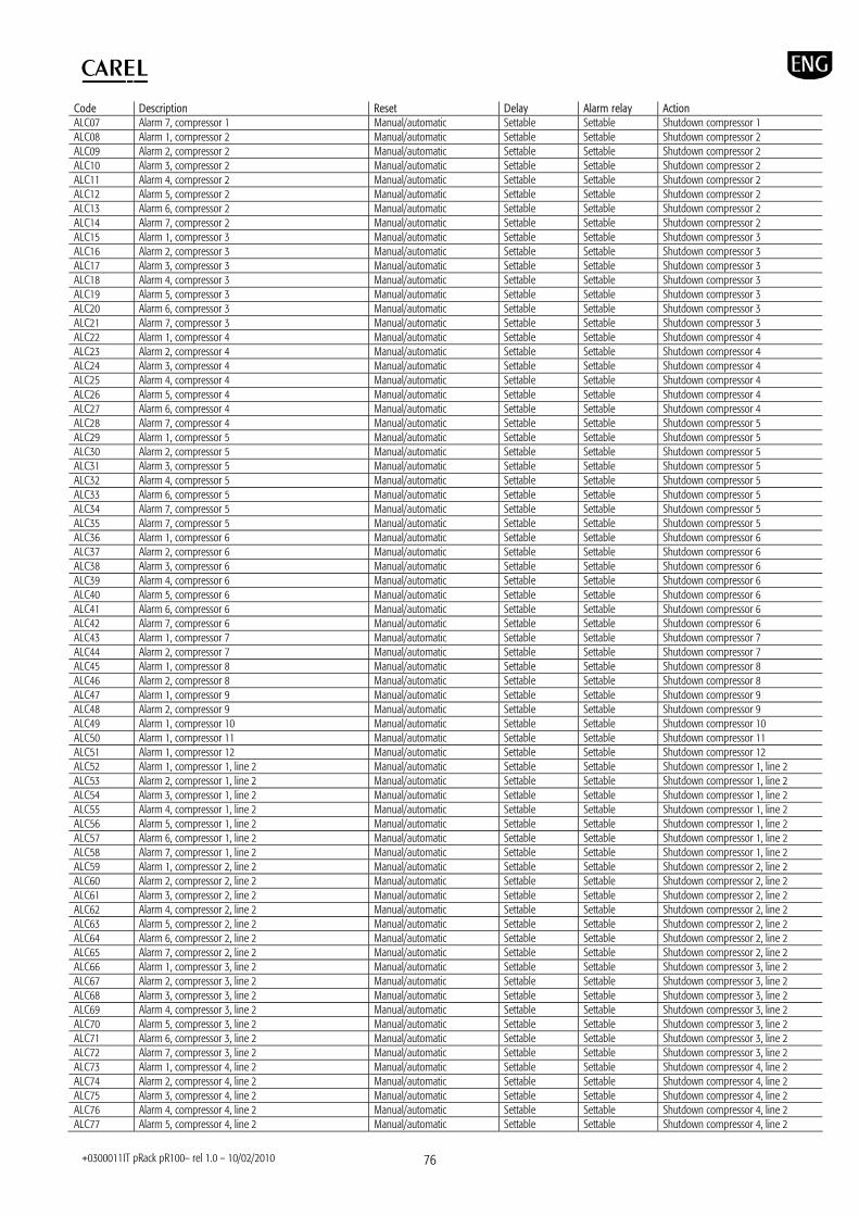
+0300011IT pRack pR100– rel 1.0 – 10/02/2010 76
Code Description Reset Delay Alarm relay Action ALC07 Alarm 7, compressor 1 Manual/automatic Settable Settable Shutdown compressor 1 ALC08 Alarm 1, compressor 2 Manual/automatic Settable Settable Shutdown compressor 2 ALC09 Alarm 2, compressor 2 Manual/automatic Settable Settable Shutdown compressor 2 ALC10 Alarm 3, compressor 2 Manual/automatic Settable Settable Shutdown compressor 2 ALC11 Alarm 4, compressor 2 Manual/automatic Settable Settable Shutdown compressor 2 ALC12 Alarm 5, compressor 2 Manual/automatic Settable Settable Shutdown compressor 2 ALC13 Alarm 6, compressor 2 Manual/automatic Settable Settable Shutdown compressor 2 ALC14 Alarm 7, compressor 2 Manual/automatic Settable Settable Shutdown compressor 2 ALC15 Alarm 1, compressor 3 Manual/automatic Settable Settable Shutdown compressor 3 ALC16 Alarm 2, compressor 3 Manual/automatic Settable Settable Shutdown compressor 3 ALC17 Alarm 3, compressor 3 Manual/automatic Settable Settable Shutdown compressor 3 ALC18 Alarm 4, compressor 3 Manual/automatic Settable Settable Shutdown compressor 3 ALC19 Alarm 5, compressor 3 Manual/automatic Settable Settable Shutdown compressor 3 ALC20 Alarm 6, compressor 3 Manual/automatic Settable Settable Shutdown compressor 3 ALC21 Alarm 7, compressor 3 Manual/automatic Settable Settable Shutdown compressor 3 ALC22 Alarm 1, compressor 4 Manual/automatic Settable Settable Shutdown compressor 4 ALC23 Alarm 2, compressor 4 Manual/automatic Settable Settable Shutdown compressor 4 ALC24 Alarm 3, compressor 4 Manual/automatic Settable Settable Shutdown compressor 4 ALC25 Alarm 4, compressor 4 Manual/automatic Settable Settable Shutdown compressor 4 ALC26 Alarm 5, compressor 4 Manual/automatic Settable Settable Shutdown compressor 4 ALC27 Alarm 6, compressor 4 Manual/automatic Settable Settable Shutdown compressor 4 ALC28 Alarm 7, compressor 4 Manual/automatic Settable Settable Shutdown compressor 5 ALC29 Alarm 1, compressor 5 Manual/automatic Settable Settable Shutdown compressor 5 ALC30 Alarm 2, compressor 5 Manual/automatic Settable Settable Shutdown compressor 5 ALC31 Alarm 3, compressor 5 Manual/automatic Settable Settable Shutdown compressor 5 ALC32 Alarm 4, compressor 5 Manual/automatic Settable Settable Shutdown compressor 5 ALC33 Alarm 6, compressor 5 Manual/automatic Settable Settable Shutdown compressor 5 ALC34 Alarm 7, compressor 5 Manual/automatic Settable Settable Shutdown compressor 5 ALC35 Alarm 7, compressor 5 Manual/automatic Settable Settable Shutdown compressor 5 ALC36 Alarm 1, compressor 6 Manual/automatic Settable Settable Shutdown compressor 6 ALC37 Alarm 2, compressor 6 Manual/automatic Settable Settable Shutdown compressor 6 ALC38 Alarm 3, compressor 6 Manual/automatic Settable Settable Shutdown compressor 6 ALC39 Alarm 4, compressor 6 Manual/automatic Settable Settable Shutdown compressor 6 ALC40 Alarm 5, compressor 6 Manual/automatic Settable Settable Shutdown compressor 6 ALC41 Alarm 6, compressor 6 Manual/automatic Settable Settable Shutdown compressor 6 ALC42 Alarm 7, compressor 6 Manual/automatic Settable Settable Shutdown compressor 6 ALC43 Alarm 1, compressor 7 Manual/automatic Settable Settable Shutdown compressor 7 ALC44 Alarm 2, compressor 7 Manual/automatic Settable Settable Shutdown compressor 7 ALC45 Alarm 1, compressor 8 Manual/automatic Settable Settable Shutdown compressor 8 ALC46 Alarm 2, compressor 8 Manual/automatic Settable Settable Shutdown compressor 8 ALC47 Alarm 1, compressor 9 Manual/automatic Settable Settable Shutdown compressor 9 ALC48 Alarm 2, compressor 9 Manual/automatic Settable Settable Shutdown compressor 9 ALC49 Alarm 1, compressor 10 Manual/automatic Settable Settable Shutdown compressor 10 ALC50 Alarm 1, compressor 11 Manual/automatic Settable Settable Shutdown compressor 11 ALC51 Alarm 1, compressor 12 Manual/automatic Settable Settable Shutdown compressor 12 ALC52 Alarm 1, compressor 1, line 2 Manual/automatic Settable Settable Shutdown compressor 1, line 2 ALC53 Alarm 2, compressor 1, line 2 Manual/automatic Settable Settable Shutdown compressor 1, line 2 ALC54 Alarm 3, compressor 1, line 2 Manual/automatic Settable Settable Shutdown compressor 1, line 2 ALC55 Alarm 4, compressor 1, line 2 Manual/automatic Settable Settable Shutdown compressor 1, line 2 ALC56 Alarm 5, compressor 1, line 2 Manual/automatic Settable Settable Shutdown compressor 1, line 2 ALC57 Alarm 6, compressor 1, line 2 Manual/automatic Settable Settable Shutdown compressor 1, line 2 ALC58 Alarm 7, compressor 1, line 2 Manual/automatic Settable Settable Shutdown compressor 1, line 2 ALC59 Alarm 1, compressor 2, line 2 Manual/automatic Settable Settable Shutdown compressor 2, line 2 ALC60 Alarm 2, compressor 2, line 2 Manual/automatic Settable Settable Shutdown compressor 2, line 2 ALC61 Alarm 3, compressor 2, line 2 Manual/automatic Settable Settable Shutdown compressor 2, line 2 ALC62 Alarm 4, compressor 2, line 2 Manual/automatic Settable Settable Shutdown compressor 2, line 2 ALC63 Alarm 5, compressor 2, line 2 Manual/automatic Settable Settable Shutdown compressor 2, line 2 ALC64 Alarm 6, compressor 2, line 2 Manual/automatic Settable Settable Shutdown compressor 2, line 2 ALC65 Alarm 7, compressor 2, line 2 Manual/automatic Settable Settable Shutdown compressor 2, line 2 ALC66 Alarm 1, compressor 3, line 2 Manual/automatic Settable Settable Shutdown compressor 3, line 2 ALC67 Alarm 2, compressor 3, line 2 Manual/automatic Settable Settable Shutdown compressor 3, line 2 ALC68 Alarm 3, compressor 3, line 2 Manual/automatic Settable Settable Shutdown compressor 3, line 2 ALC69 Alarm 4, compressor 3, line 2 Manual/automatic Settable Settable Shutdown compressor 3, line 2 ALC70 Alarm 5, compressor 3, line 2 Manual/automatic Settable Settable Shutdown compressor 3, line 2 ALC71 Alarm 6, compressor 3, line 2 Manual/automatic Settable Settable Shutdown compressor 3, line 2 ALC72 Alarm 7, compressor 3, line 2 Manual/automatic Settable Settable Shutdown compressor 3, line 2 ALC73 Alarm 1, compressor 4, line 2 Manual/automatic Settable Settable Shutdown compressor 4, line 2 ALC74 Alarm 2, compressor 4, line 2 Manual/automatic Settable Settable Shutdown compressor 4, line 2 ALC75 Alarm 3, compressor 4, line 2 Manual/automatic Settable Settable Shutdown compressor 4, line 2 ALC76 Alarm 4, compressor 4, line 2 Manual/automatic Settable Settable Shutdown compressor 4, line 2 ALC77 Alarm 5, compressor 4, line 2 Manual/automatic Settable Settable Shutdown compressor 4, line 2

+0300011IT pRack pR100– rel 1.0 – 10/02/2010 77
Code Description Reset Delay Alarm relay Action ALC78 Alarm 6, compressor 4, line 2 Manual/automatic Settable Settable Shutdown compressor 4, line 2 ALC79 Alarm 7, compressor 4, line 2 Manual/automatic Settable Settable Shutdown compressor 4, line 2 ALC80 Alarm 1, compressor 5, line 2 Manual/automatic Settable Settable Shutdown compressor 5, line 2 ALC81 Alarm 2, compressor 5, line 2 Manual/automatic Settable Settable Shutdown compressor 5, line 2 ALC82 Alarm 3, compressor 5, line 2 Manual/automatic Settable Settable Shutdown compressor 5, line 2 ALC83 Alarm 4, compressor 5, line 2 Manual/automatic Settable Settable Shutdown compressor 5, line 2 ALC84 Alarm 5, compressor 5, line 2 Manual/automatic Settable Settable Shutdown compressor 5, line 2 ALC85 Alarm 6, compressor 5, line 2 Manual/automatic Settable Settable Shutdown compressor 5, line 2 ALC86 Alarm 7, compressor 5, line 2 Manual/automatic Settable Settable Shutdown compressor 5, line 2 ALC87 Alarm 1, compressor 6, line 2 Manual/automatic Settable Settable Shutdown compressor 6, line 2 ALC88 Alarm 2, compressor 6, line 2 Manual/automatic Settable Settable Shutdown compressor 6, line 2 ALC89 Alarm 3, compressor 6, line 2 Manual/automatic Settable Settable Shutdown compressor 6, line 2 ALC90 Alarm 4, compressor 6, line 2 Manual/automatic Settable Settable Shutdown compressor 6, line 2 ALC91 Alarm 5, compressor 6, line 2 Manual/automatic Settable Settable Shutdown compressor 6, line 2 ALC92 Alarm 6, compressor 6, line 2 Manual/automatic Settable Settable Shutdown compressor 6, line 2 ALC93 Alarm 7, compressor 6, line 2 Manual/automatic Settable Settable Shutdown compressor 6, line 2 ALC94 Alarm 1, compressor 7, line 2 Manual/automatic Settable Settable Shutdown compressor 7, line 2 ALC95 Alarm 2, compressor 7, line 2 Manual/automatic Settable Settable Shutdown compressor 7, line 2 ALC96 Alarm 1, compressor 8, line 2 Manual/automatic Settable Settable Shutdown compressor 8, line 2 ALC97 Alarm 2, compressor 8, line 2 Manual/automatic Settable Settable Shutdown compressor 8, line 2 ALC98 Alarm 1, compressor 9, line 2 Manual/automatic Settable Settable Shutdown compressor 9, line 2 ALC99 Alarm 2, compressor 9, line 2 Manual/automatic Settable Settable Shutdown compressor 9, line 2 ALCaa Alarm 1, compressor 10, line 2 Manual/automatic Settable Settable Shutdown compressor 10, line 2 ALCab Alarm 1, compressor 11, line 2 Manual/automatic Settable Settable Shutdown compressor 11, line 2 ALCac Alarm 1, compressor 12, line 2 Manual/automatic Settable Settable Shutdown compressor 12, line 2 ALCad High oil sump temperature, Digital Scroll™ Manual/automatic Settable R2 Shutdown compressor ALCae High discharge temperature, Digital Scroll™ Manual/automatic Settable R2 Shutdown compressor ALCaf High oil dilution, Digital Scroll™ Manual/automatic Settable R2 Shutdown compressor ALCag High oil sump temperature, Digital Scroll™, line 2 Manual/automatic Settable R2 Shutdown compressor ALCah High discharge temperature, Digital Scroll™, line 2 Manual/automatic Settable R2 Shutdown compressor ALCai High oil dilution, Digital Scroll™, line 2 Manual/automatic Settable R2 Shutdown compressor ALCal High discharge temperature compressors 1 to 6 Automatic 60s R2 Related functions disabled ALCam High discharge temperature compressors 1 to 6, line 2 Automatic 60s R2 Related functions disabled AlCan Compressor envelope Manual Settable R1 Shutdown compressor ALCao High compressor oil temperature, line 1 Automatic Settable R2 - AlCap High compressor oil temperature, line 2 Automatic Settable R2 - ALF01 Fan circuit breaker Manual/automatic Settable R2 Shutdown fans ALF02 Fan circuit breaker, line 2 Manual/automatic Settable R2 Shutdown fans ALG01 Clock error Automatic - R2 Related functions disabled ALG02 Extended memory error Automatic - R2 Related functions disabled ALG11 Generic high temperature alarms 1 to 5, PLB1 Manual/automatic Settable Settable - ALG12 Generic high temperature alarms 1 to 5, PLB2 Manual/automatic Settable Settable - ALG13 Generic high temperature alarms 1 to 5, PLB3 Manual/automatic Settable Settable - ALG14 Generic high temperature alarms 1 to 5, PLB4 Manual/automatic Settable Settable - ALG15 Generic low temperature alarms 1 to 5, PLB1 Manual/automatic Settable Settable - ALG16 Generic low temperature alarms 1 to 5, PLB2 Manual/automatic Settable Settable - ALG17 Generic low temperature alarms 1 to 5, PLB3 Manual/automatic Settable Settable - ALG18 Generic low temperature alarms 1 to 5, PLB4 Manual/automatic Settable Settable - ALG19 Generic high modulation alarms 6 and 7, PLB1 Manual/automatic Settable Settable - ALG20 Generic high modulation alarms 6 and 7, PLB2 Manual/automatic Settable Settable - ALG21 Generic high modulation alarms 6 and 7, PLB3 Manual/automatic Settable Settable - ALG22 Generic high modulation alarms 6 and 7, PLB4 Manual/automatic Settable Settable - ALG23 Generic low modulation alarms 6 and 7, PLB1 Manual/automatic Settable Settable - ALG24 Generic low modulation alarms 6 and 7, PLB2 Manual/automatic Settable Settable - ALG25 Generic low modulation alarms 6 and 7, PLB3 Manual/automatic Settable Settable - ALG26 Generic low modulation alarms 6 and 7, PLB4 Manual/automatic Settable Settable - ALG27 Normal alarm generic functions 8/9, PLB1 Manual/automatic Settable Settable - ALG28 Serious alarm generic functions 8/9, PLB1 Manual/automatic Settable Settable - ALG29 Normal alarm generic functions 8/9, PLB2 Manual/automatic Settable Settable - ALG30 Serious alarm generic functions 8/9, PLB2 Manual/automatic Settable Settable - ALG31 Normal alarm generic functions 8/9, PLB3 Manual/automatic Settable Settable - ALG32 Serious alarm generic functions 8/9, PLB3 Manual/automatic Settable Settable - ALG33 Normal alarm generic functions 8/9, PLB4 Manual/automatic Settable Settable - ALG34 Serious alarm generic functions 8/9, PLB4 Manual/automatic Settable Settable - ALH01 ChillBooster fault Automatic Settable R2 Disable ChillBooster ALH02 ChillBooster fault, line 2 Automatic Settable R2 Disable ChillBooster ALO02 pLAN malfunction Automatic 60s R1 Shutdown unit ALT01 Compressor maintenance request Manual - Not featured - ALT02 Compressor maintenance request, line 2 Manual - Not featured - ALT03 ChillBooster maintenance request manual 0s Not featured - ALT04 ChillBooster maintenance request, line 2 manual 0s Not featured -

+0300011IT pRack pR100– rel 1.0 – 10/02/2010 78
Code Description Reset Delay Alarm relay Action ALU01 Configuration not allowed Automatic Not featured Not featured Shutdown unit ALU02 Control probes missing Automatic Not featured Not featured Shutdown unit
ALW01 High pressure prevent warning Automatic Settable Not featured Shutdown compressor, except minimum load stage
ALW02 High pressure prevent warning, line 2 Automatic Settable Not featured Shutdown compressor line 2, except minimum load stage
ALW03 Compressor inverter warning Automatic Not featured Not featured - ALW04 Compressor inverter warning, line 2 Automatic Not featured Not featured - ALW05 Fan inverter warning Automatic Not featured Not featured - ALW06 Fan inverter warning, line 2 Automatic Not featured Not featured -
ALW07 Envelope warning: refrigerant not compatible with compressor series Automatic Not featured Not featured -
ALW08 Envelope warning: custom envelope not configured Automatic Not featured Not featured -
ALW09 Envelope warning: suction or condensing probes not configured
Automatic Not featured Not featured -
ALW10 Low superheat warning Automatic Not featured Not featured - ALW11 Low superheat warning, line 2 Automatic Not featured Not featured - ALW12 Warning, ChillBooster operating without outside sensor Automatic 0s Not featured -
ALW13 Warning, ChillBooster operating without outside sensor, line 2
Automatic 0s Not featured -
ALW14 Warning, probe type configured not allowed Automatic Not featured Not featured - ALW15 Warning, error during self-configuration Automatic Not featured Not featured -
CAREL reserves the right to modify or change its products without prior warning

+0300011IT pRack pR100– rel 1.0 – 10/02/2010 79

+0300011IT pRack pR100– rel 1.0 – 10/02/2010 80
CAREL INDUSTRIES HQs Via dell’Industria, 11 - 35020 Brugine - Padova (Italy) Tel. (+39) 049.9716611 Fax (+39) 049.9716600 http://www.carel.com - e-mail: [email protected]
+030
0011
EN p
Rack
pR1
00–
rel 1
.0 –
10/
02/2
010