Care and Operation - Hearth N Homedownloads.hearthnhome.com/installManuals/2310_971.pdf · Care and...
37
1 Heat & Glo • PRIMO48, PRIMO48ST, PRIMO60, PRIMO60ST, PRIMO72, PRIMO72ST Owner’s Manual • 2310-971 Rev. M • 12/17 Owner’s Manual Care and Operation NOTICE: DO NOT discard this manual! In the Commonwealth of Massachusetts installation must be performed by a licensed plumber or gas fitter. See appliance Installation Manual for additional Commonwealth of Massachusetts requirements. INSTALLER: Leave this manual with party responsible for use and operation. OWNER: Retain this manual for future reference. Contact your dealer with questions regarding installation, operation or service. This appliance may be installed as an OEM installation in manufactured home (USA only) or mobile home and must be installed in accordance with the manufacturer’s instructions and the Manufactured Home Construction and Safety Standard, Title 24 CFR, Part 3280 in the United States, or the Standard for Installation in Mobile Homes, CAN/CSA Z240 MH Series, in Canada. This appliance is only for use with the type(s) of gas indicated on the rating plate. This appliance is not convertible for use with other gases, unless a certified kit is used. DANGER HOT GLASS WILL CAUSE BURNS. DO NOT TOUCH GLASS UNTIL COOLED. NEVER ALLOW CHILDREN TO TOUCH GLASS. A (glass) barrier designed to reduce the risk of burns from the hot viewing glass is provided with this appliance and shall be installed for the protection of children and other at-risk individuals. • DO NOT store or use gasoline or other flam- mable vapors and liquids in the vicinity of this or any other appliance. • What to do if you smell gas - DO NOT try to light any appliance. - DO NOT touch any electrical switch. DO NOT use any phone in your building. - Leave the building immediately. - Immediately call your gas supplier from a neighbor’s phone. Follow the gas sup- plier’s instructions. - If you cannot reach your gas supplier, call the fire department. • Installation and service must be performed by a qualified installer, service agency, or the gas supplier. WARNING: FIRE OR EXPLOSION HAZARD Failure to follow safety warnings exactly could result in serious injury, death, or property damage. This appliance comes standard with patented SafeSurface TM Glass which keeps the surface temperature of the barrier glass at a safe level and will still be hot to the touch when operated for long periods of time. SafeSurface TM Glass complies with the barrier requirements of ANSI Z21.50-2014 CSA 2.22-2014 for vented gas fireplaces.If the barrier glass is removed, the inner glass temperature will be very hot and cause burns. Models: PRIMO48 PRIMO48ST PRIMO60 PRIMO60ST PRIMO72 PRIMO72ST Pour demander un exemplaire en français de ce Manuel du propriétaire, visitez www.heatnglo.com/translations.
-
Upload
nguyenkhue -
Category
Documents
-
view
221 -
download
2
Transcript of Care and Operation - Hearth N Homedownloads.hearthnhome.com/installManuals/2310_971.pdf · Care and...

1Heat & Glo • PRIMO48, PRIMO48ST, PRIMO60, PRIMO60ST, PRIMO72, PRIMO72ST Owner’s Manual • 2310-971 Rev. M • 12/17
Owner’s ManualCare and Operation
NOTICE: DO NOT discard this manual!
In the Commonwealth of Massachusetts installation must be performed by a licensed plumber or gas fitter.See appl iance Instal lat ion Manual for addit ional Commonwealth of Massachusetts requirements.
INSTALLER: Leave this manual with party responsible for use and operation.OWNER: Retain this manual for future reference. Contact your dealer with questions regarding
installation, operation or service.
This appliance may be installed as an OEM installation in manufactured home (USA only) or mobile home and must be installed in accordance with the manufacturer’s instructions and the Manufactured Home Construction and Safety Standard, Title 24 CFR, Part 3280 in the United States, or the Standard for Installation in Mobile Homes, CAN/CSA Z240 MH Series, in Canada.This appliance is only for use with the type(s) of gas indicated on the rating plate. This appliance is not convertible for use with other gases, unless a certified kit is used.
DANGERHOT GLASS WILL CAUSE BURNS.
DO NOT TOUCH GLASS UNTIL COOLED.
NEVER ALLOW CHILDREN TO TOUCH GLASS.
A (glass) barrier designed to reduce the risk of burns from the hot viewing glass is provided with this appliance and shall be installed for the protection of children and other at-risk individuals.
• DO NOT store or use gasoline or other flam-mable vapors and liquids in the vicinity of this or any other appliance.
• What to do if you smell gas - DO NOT try to light any appliance.- DO NOT touch any electrical switch. DO
NOT use any phone in your building.- Leave the building immediately.- Immediately call your gas supplier from
a neighbor’s phone. Follow the gas sup-plier’s instructions.
- If you cannot reach your gas supplier, call the fire department.
• Installation and service must be performed by a qualified installer, service agency, or the gas supplier.
WARNING: FIRE OR EXPLOSION HAZARDFailure to follow safety warnings exactly could result in serious injury, death, or property damage.
This appliance comes standard with patented SafeSurfaceTM Glass which keeps the surface temperature of the barrier glass at a safe level and will still be hot to the touch when operated for long periods of time. SafeSurfaceTM Glass complies with the barrier requirements of ANSI Z21.50-2014 CSA 2.22-2014 for vented gas fireplaces.If the barrier glass is removed, the inner glass temperature will be very hot and cause burns.
Models:PRIMO48PRIMO48STPRIMO60PRIMO60STPRIMO72PRIMO72ST
Pour demander un exemplaire en français de ce Manuel du propriétaire, visitez www.heatnglo.com/translations.
Heat & Glo • PRIMO48, PRIMO48ST, PRIMO60, PRIMO60ST, PRIMO72, PRIMO72ST Owner’s Manual • 2310-971 Rev. M • 12/17 2
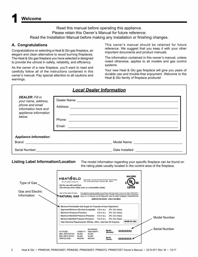
Listing Label Information/Location
A. CongratulationsCongratulations on selecting a Heat & Glo gas fireplace, an elegant and clean alternative to wood burning fireplaces. The Heat & Glo gas fireplace you have selected is designed to provide the utmost in safety, reliability, and efficiency.As the owner of a new fireplace, you’ll want to read and carefully follow all of the instructions contained in this owner’s manual. Pay special attention to all cautions and warnings.
This owner’s manual should be retained for future reference. We suggest that you keep it with your other important documents and product manuals.The information contained in this owner’s manual, unless noted otherwise, applies to all models and gas control systems.Your new Heat & Glo gas fireplace will give you years of durable use and trouble-free enjoyment. Welcome to the Heat & Glo family of fireplace products!
Gas and Electric Information
Serial Number
Type of Gas
The model information regarding your specific fireplace can be found on the rating plate usually located in the control area of the fireplace.
Model Number
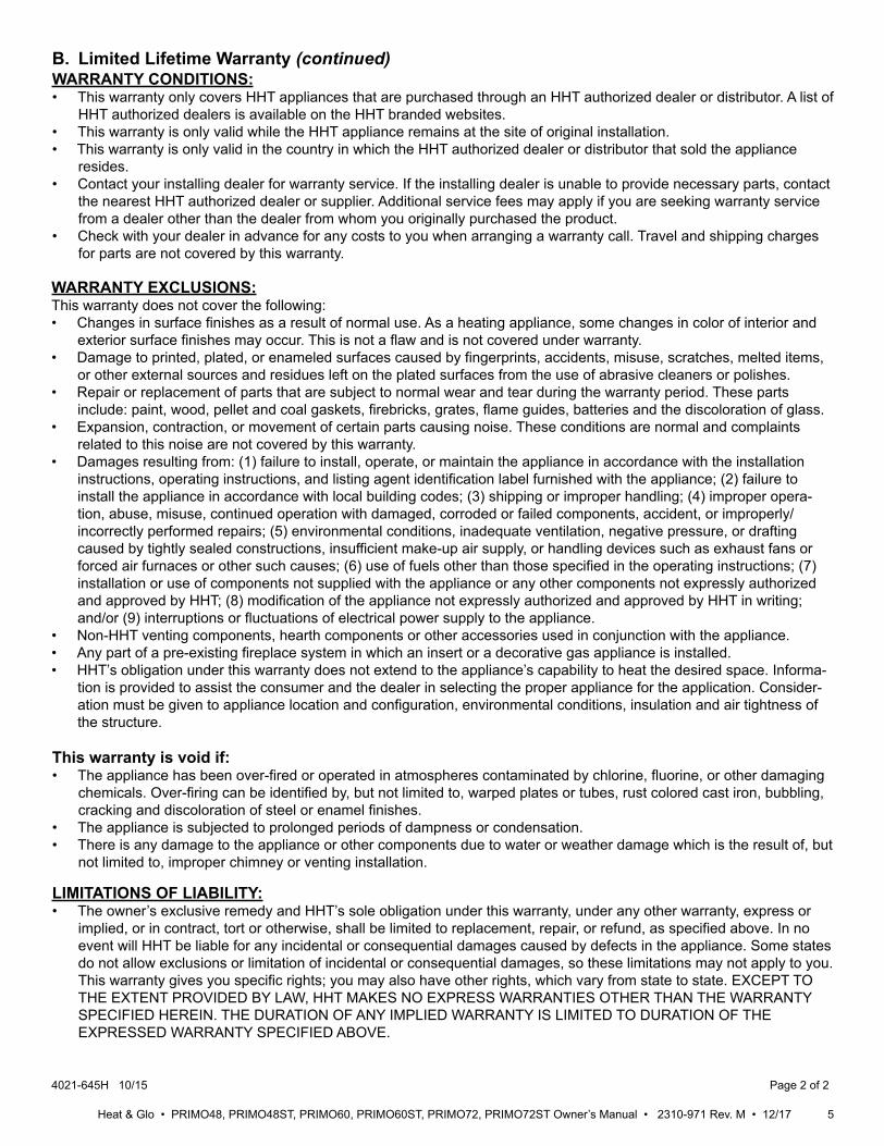
Not Not for for use use with with solid solid fuel.fuel.((Ne Ne doit doit pas pas entre entre utilise utilise avec avec un un combustible combustible solide).solide).
This This appliance appliance must must be be installed installed in in accordance accordance with with local local codes, codes, if if any; any; if if not, not, follow follow ANSI ANSI Z223.1Z223.1in in the the USA USA or or CAN/CGA CAN/CGA B149 B149 installation installation codes. codes. (Installer (Installer l’appareil l’appareil selon selon les les codes codes ou ou reglementsreglementslocaux locaux ou, ou, en en l’absence l’absence de de tels tels reglements, reglements, selon selon les les codes codes d’installation d’installation CAN/CGA-B149.)CAN/CGA-B149.)
Type Type of of Gas Gas (Sorte (Sorte De De Gaz)Gaz)::
NNAATURALTURAL GASGAS
MADE MADE IN IN USAUSA
Minimum Minimum Permissible Permissible Gas Gas Supply Supply for for Purposes Purposes of of Input Input Adjustment.Adjustment.Approved Approved Minimum Minimum (De (De Gaz) Gaz) AcceptableAcceptable 0.00.0 in in w.c.w.c. (Po. (Po. Col. Col. d’eau)d’eau)Maximum Maximum Pressure Pressure (Pression)(Pression) 0.00.0 in in w.c.w.c. (Po. (Po. Col. Col. d’eau)d’eau)Maximum Maximum Manifold Manifold Pressure Pressure (Pression)(Pression) 0.00.0 in in w.c.w.c. (Po. (Po. Col. Col. d’eau)d’eau)Minimum Minimum Manifold Manifold Pressure Pressure (Pression)(Pression) 0.00.0 in in w.c.w.c. (Po. (Po. Col. Col. d’eau)d’eau)
Model:Model:(Modele):(Modele):
SerialSerial(Serie):(Serie):
ANSI ANSI Z21XX-XXXX Z21XX-XXXX · · CSA CSA 2.XX-MXX 2.XX-MXX
XXXXXXXXXXXXXXXXIN IN CANADACANADA
ALTITUDE:ALTITUDE: 0-0000 0-0000 FT.FT. 0000-0000FT.0000-0000FT.MAX. MAX. INPUT INPUT BTUH:BTUH: 00,00000,000 00,00000,000MIN. MIN. INPUT INPUT BTUH:BTUH: 00,00000,000 00,00000,000ORIFICE ORIFICE SIZE:SIZE: #XXXXX#XXXXX #XXXXX#XXXXX XXXXXXXXXXXXXXXX
Total Total Electrical Electrical Requirements: Requirements: 000Vac, 000Vac, 00Hz., 00Hz., less less than than 00 00 AmperesAmperes
Heat & Glo, a brand of Hearth & Home Technologies7571 215th Street West, Lakeville, MN 55044
Read this manual before operating this appliance. Please retain this Owner’s Manual for future reference.
Read the Installation Manual before making any installation or finishing changes.
1 Welcome
Brand: ________________________________________________ Model Name: ___________________________
Serial Number: __________________________________________ Date Installed: __________________________
Appliance Information:
Local Dealer InformationDEALER: Fill in your name, address, phone and email information here and appliance information below.
Dealer Name: ________________________________________________________
Address: ____________________________________________________________
____________________________________________________________
Phone: _____________________________________________________________
Email: _____________________________________________________________
3Heat & Glo • PRIMO48, PRIMO48ST, PRIMO60, PRIMO60ST, PRIMO72, PRIMO72ST Owner’s Manual • 2310-971 Rev. M • 12/17
Safety Alert Key:• DANGER! Indicates a hazardous situation which, if not avoided will result in death or serious injury.• WARNING! Indicates a hazardous situation which, if not avoided could result in death or serious injury.• CAUTION! Indicates a hazardous situation which, if not avoided, could result in minor or moderate injury.• NOTICE: Used to address practices not related to personal injury.
Table of Contents
1 Welcome A. Congratulations . . . . . . . . . . . . . . . . . . . . . . . . . . . . . . . . . 2B. Limited Lifetime Warranty . . . . . . . . . . . . . . . . . . . . . . . . . . 4
2 Product Specific Information A. Appliance Certification . . . . . . . . . . . . . . . . . . . . . . . . . . . . 6B. Glass Specifications . . . . . . . . . . . . . . . . . . . . . . . . . . . . . . 6C. BTU Specifications . . . . . . . . . . . . . . . . . . . . . . . . . . . . . . . 6
3 Important Safety and Operating Information A. Appliance Safety . . . . . . . . . . . . . . . . . . . . . . . . . . . . . . . . 7B. General Operating Parts . . . . . . . . . . . . . . . . . . . . . . . . . . 8C. Fuel Specifications . . . . . . . . . . . . . . . . . . . . . . . . . . . . . . . 8D. Good Faith Wall Surface/TV Guidelines . . . . . . . . . . . . . . 8E. Before Lighting Appliance. . . . . . . . . . . . . . . . . . . . . . . . . 10F. Lighting Instructions (IPI) . . . . . . . . . . . . . . . . . . . . . . . . . 11G. Appliance Break-In . . . . . . . . . . . . . . . . . . . . . . . . . . . . . . 12H. Heat Management . . . . . . . . . . . . . . . . . . . . . . . . . . . . . . 12I. Operation During A Power Outage . . . . . . . . . . . . . . . . . . 12J. Detailed Component Operating Instructions . . . . . . . . . . . 13
4 Maintenance and Service A. Maintenance: Frequency and Tasks . . . . . . . . . . . . . . . . 16B. Maintenance Tasks: Homeowner . . . . . . . . . . . . . . . . . . 16C. Maintenance Tasks: Qualified Service Technician . . . . . 18
5 Frequently Asked Questions and Troubleshooting A. Frequently Asked Questions . . . . . . . . . . . . . . . . . . . . . . 22B. Troubleshooting . . . . . . . . . . . . . . . . . . . . . . . . . . . . . . . . 23C. PVLP-SLP Power Vent Troubleshooting . . . . . . . . . . . . . 25D. PVI-SLP-B Power Vent Troubleshooting. . . . . . . . . . . . . . 26
6 Reference Materials A. Accessories . . . . . . . . . . . . . . . . . . . . . . . . . . . . . . . . . . . 27B. Service Parts . . . . . . . . . . . . . . . . . . . . . . . . . . . . . . . . . . 28C. Contact Information . . . . . . . . . . . . . . . . . . . . . . . . . . . . . 37
= Contains updated information.
Heat & Glo • PRIMO48, PRIMO48ST, PRIMO60, PRIMO60ST, PRIMO72, PRIMO72ST Owner’s Manual • 2310-971 Rev. M • 12/17 4
B. Limited Lifetime Warranty
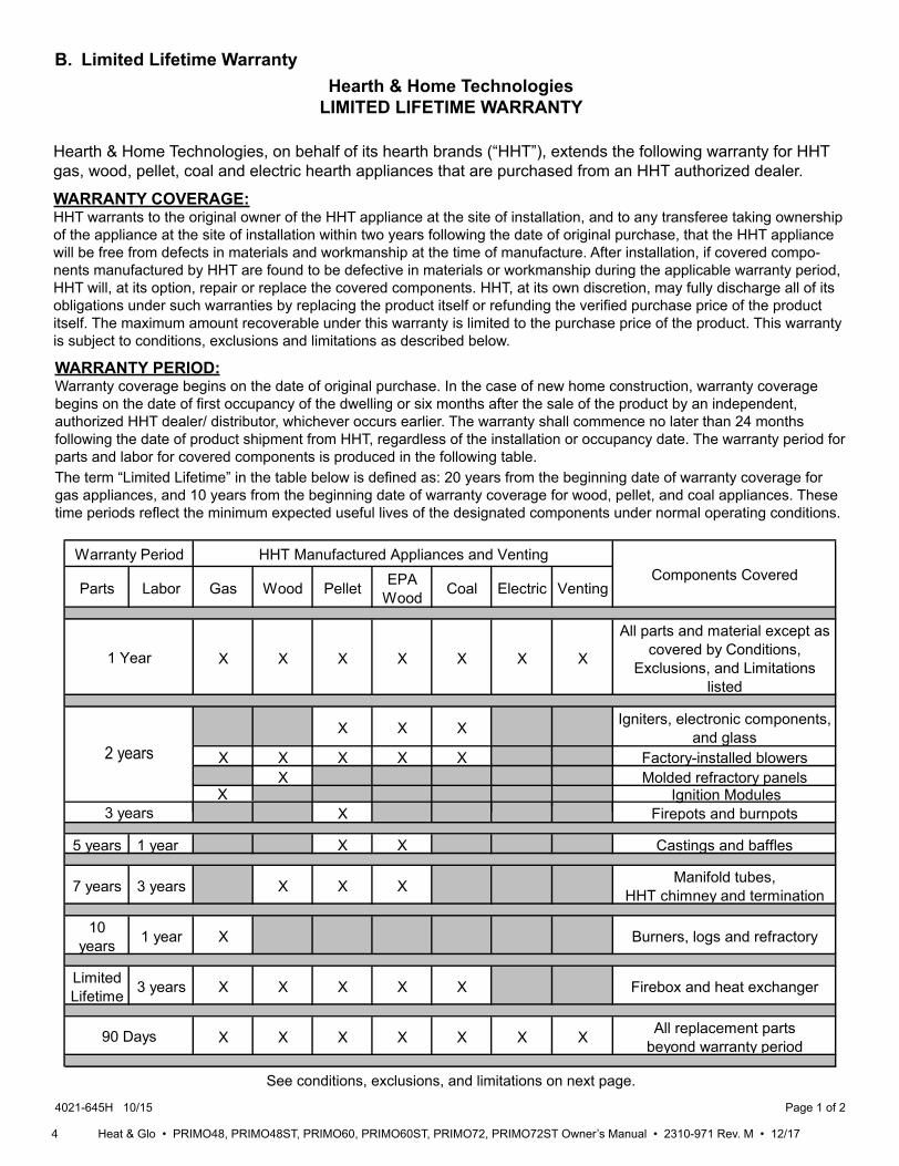
X Molded refractory panels
4021-645H 10/15 Page 1 of 2
Hearth & Home TechnologiesLIMITED LIFETIME WARRANTY
Hearth & Home Technologies, on behalf of its hearth brands (“HHT”), extends the following warranty for HHT gas, wood, pellet, coal and electric hearth appliances that are purchased from an HHT authorized dealer.
WARRANTY COVERAGE:HHT warrants to the original owner of the HHT appliance at the site of installation, and to any transferee taking ownership of the appliance at the site of installation within two years following the date of original purchase, that the HHT appliance will be free from defects in materials and workmanship at the time of manufacture. After installation, if covered compo-nents manufactured by HHT are found to be defective in materials or workmanship during the applicable warranty period, HHT will, at its option, repair or replace the covered components. HHT, at its own discretion, may fully discharge all of its obligations under such warranties by replacing the product itself or refunding the verified purchase price of the product itself. The maximum amount recoverable under this warranty is limited to the purchase price of the product. This warranty is subject to conditions, exclusions and limitations as described below.
WARRANTY PERIOD:Warranty coverage begins on the date of original purchase. In the case of new home construction, warranty coverage begins on the date of first occupancy of the dwelling or six months after the sale of the product by an independent, authorized HHT dealer/ distributor, whichever occurs earlier. The warranty shall commence no later than 24 months following the date of product shipment from HHT, regardless of the installation or occupancy date. The warranty period for parts and labor for covered components is produced in the following table.The term “Limited Lifetime” in the table below is defined as: 20 years from the beginning date of warranty coverage for gas appliances, and 10 years from the beginning date of warranty coverage for wood, pellet, and coal appliances. These time periods reflect the minimum expected useful lives of the designated components under normal operating conditions.
See conditions, exclusions, and limitations on next page.
Parts Labor Gas Wood Pellet EPAWood Coal Electric Venting
X X X X X X X
All parts and material except as covered by Conditions,
Exclusions, and Limitations listed
X X X Igniters, electronic components, and glass
X X X X X Factory-installed blowers
X Firepots and burnpots
5 years 1 year X X Castings and baffles
7 years 3 years X X X Manifold tubes, HHT chimney and termination
10years 1 year X Burners, logs and refractory
Limited Lifetime 3 years X X X X X Firebox and heat exchanger
X X X X X X X All replacement partsbeyond warranty period
Warranty Period HHT Manufactured Appliances and Venting
1 Year
Components Covered
3 years
2 years
90 Days
X Ignition Modules
5Heat & Glo • PRIMO48, PRIMO48ST, PRIMO60, PRIMO60ST, PRIMO72, PRIMO72ST Owner’s Manual • 2310-971 Rev. M • 12/17
B. Limited Lifetime Warranty (continued)WARRANTY CONDITIONS:• This warranty only covers HHT appliances that are purchased through an HHT authorized dealer or distributor. A list of
HHT authorized dealers is available on the HHT branded websites.• This warranty is only valid while the HHT appliance remains at the site of original installation.• This warranty is only valid in the country in which the HHT authorized dealer or distributor that sold the appliance
resides.• Contact your installing dealer for warranty service. If the installing dealer is unable to provide necessary parts, contact
the nearest HHT authorized dealer or supplier. Additional service fees may apply if you are seeking warranty service from a dealer other than the dealer from whom you originally purchased the product.
• Check with your dealer in advance for any costs to you when arranging a warranty call. Travel and shipping charges for parts are not covered by this warranty.
This warranty is void if:• The appliance has been over-fired or operated in atmospheres contaminated by chlorine, fluorine, or other damaging
chemicals. Over-firing can be identified by, but not limited to, warped plates or tubes, rust colored cast iron, bubbling, cracking and discoloration of steel or enamel finishes.
• The appliance is subjected to prolonged periods of dampness or condensation.• There is any damage to the appliance or other components due to water or weather damage which is the result of, but
not limited to, improper chimney or venting installation.
LIMITATIONS OF LIABILITY:• The owner’s exclusive remedy and HHT’s sole obligation under this warranty, under any other warranty, express or
implied, or in contract, tort or otherwise, shall be limited to replacement, repair, or refund, as specified above. In no event will HHT be liable for any incidental or consequential damages caused by defects in the appliance. Some states do not allow exclusions or limitation of incidental or consequential damages, so these limitations may not apply to you. This warranty gives you specific rights; you may also have other rights, which vary from state to state. EXCEPT TO THE EXTENT PROVIDED BY LAW, HHT MAKES NO EXPRESS WARRANTIES OTHER THAN THE WARRANTY SPECIFIED HEREIN. THE DURATION OF ANY IMPLIED WARRANTY IS LIMITED TO DURATION OF THE EXPRESSED WARRANTY SPECIFIED ABOVE.
WARRANTY EXCLUSIONS:This warranty does not cover the following:• Changes in surface finishes as a result of normal use. As a heating appliance, some changes in color of interior and
exterior surface finishes may occur. This is not a flaw and is not covered under warranty.• Damage to printed, plated, or enameled surfaces caused by fingerprints, accidents, misuse, scratches, melted items,
or other external sources and residues left on the plated surfaces from the use of abrasive cleaners or polishes.• Repair or replacement of parts that are subject to normal wear and tear during the warranty period. These parts
include: paint, wood, pellet and coal gaskets, firebricks, grates, flame guides, batteries and the discoloration of glass.• Expansion, contraction, or movement of certain parts causing noise. These conditions are normal and complaints
related to this noise are not covered by this warranty.• Damages resulting from: (1) failure to install, operate, or maintain the appliance in accordance with the installation
instructions, operating instructions, and listing agent identification label furnished with the appliance; (2) failure to install the appliance in accordance with local building codes; (3) shipping or improper handling; (4) improper opera-tion, abuse, misuse, continued operation with damaged, corroded or failed components, accident, or improperly/ incorrectly performed repairs; (5) environmental conditions, inadequate ventilation, negative pressure, or drafting caused by tightly sealed constructions, insufficient make-up air supply, or handling devices such as exhaust fans or forced air furnaces or other such causes; (6) use of fuels other than those specified in the operating instructions; (7) installation or use of components not supplied with the appliance or any other components not expressly authorized and approved by HHT; (8) modification of the appliance not expressly authorized and approved by HHT in writing; and/or (9) interruptions or fluctuations of electrical power supply to the appliance.
• Non-HHT venting components, hearth components or other accessories used in conjunction with the appliance.• Any part of a pre-existing fireplace system in which an insert or a decorative gas appliance is installed.• HHT’s obligation under this warranty does not extend to the appliance’s capability to heat the desired space. Informa-
tion is provided to assist the consumer and the dealer in selecting the proper appliance for the application. Consider-ation must be given to appliance location and configuration, environmental conditions, insulation and air tightness of the structure.
4021-645H 10/15 Page 2 of 2
Heat & Glo • PRIMO48, PRIMO48ST, PRIMO60, PRIMO60ST, PRIMO72, PRIMO72ST Owner’s Manual • 2310-971 Rev. M • 12/17 6
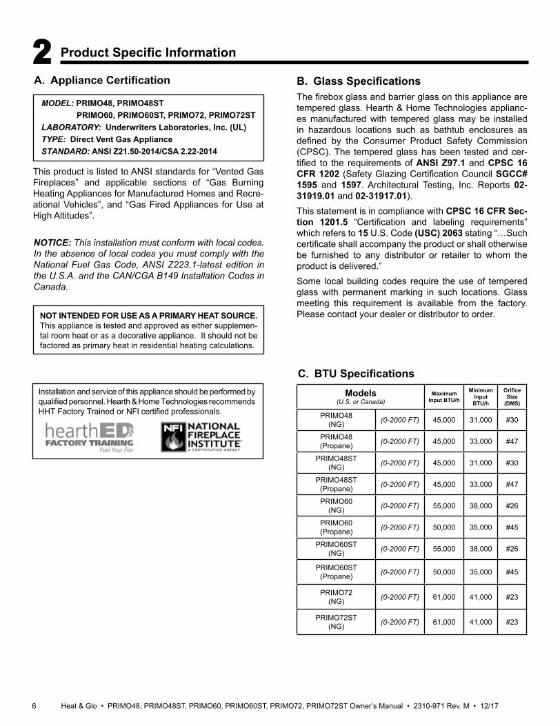
A. Appliance Certification
NOT INTENDED FOR USE AS A PRIMARY HEAT SOURCE. This appliance is tested and approved as either supplemen-tal room heat or as a decorative appliance. It should not be factored as primary heat in residential heating calculations.
NOTICE: This installation must conform with local codes. In the absence of local codes you must comply with the National Fuel Gas Code, ANSI Z223.1-latest edition in the U.S.A. and the CAN/CGA B149 Installation Codes in Canada.
2 Product Specific Information
C. BTU Specifications
This product is listed to ANSI standards for “Vented Gas Fireplaces” and applicable sections of “Gas Burning Heating Appliances for Manufactured Homes and Recre-ational Vehicles”, and “Gas Fired Appliances for Use at High Altitudes”.
B. Glass SpecificationsThe firebox glass and barrier glass on this appliance are tempered glass. Hearth & Home Technologies applianc-es manufactured with tempered glass may be installed in hazardous locations such as bathtub enclosures as defined by the Consumer Product Safety Commission (CPSC). The tempered glass has been tested and cer-tified to the requirements of ANSI Z97.1 and CPSC 16 CFR 1202 (Safety Glazing Certification Council SGCC# 1595 and 1597. Architectural Testing, Inc. Reports 02-31919.01 and 02-31917.01).This statement is in compliance with CPSC 16 CFR Sec-tion 1201.5 “Certification and labeling requirements” which refers to 15 U.S. Code (USC) 2063 stating “…Such certificate shall accompany the product or shall otherwise be furnished to any distributor or retailer to whom the product is delivered.”Some local building codes require the use of tempered glass with permanent marking in such locations. Glass meeting this requirement is available from the factory. Please contact your dealer or distributor to order.
MODEL: PRIMO48, PRIMO48ST PRIMO60, PRIMO60ST, PRIMO72, PRIMO72STLABORATORY: Underwriters Laboratories, Inc. (UL)TYPE: Direct Vent Gas ApplianceSTANDARD: ANSI Z21.50-2014/CSA 2.22-2014
Models(U.S. or Canada)
MaximumInput BTU/h
MinimumInput BTU/h
OrificeSize
(DMS)
PRIMO48(NG) (0-2000 FT) 45,000 31,000 #30
PRIMO48(Propane) (0-2000 FT) 45,000 33,000 #47
PRIMO48ST(NG) (0-2000 FT) 45,000 31,000 #30
PRIMO48ST(Propane) (0-2000 FT) 45,000 33,000 #47
PRIMO60(NG) (0-2000 FT) 55,000 38,000 #26
PRIMO60(Propane) (0-2000 FT) 50,000 35,000 #45
PRIMO60ST(NG) (0-2000 FT) 55,000 38,000 #26
PRIMO60ST(Propane) (0-2000 FT) 50,000 35,000 #45
PRIMO72(NG) (0-2000 FT) 61,000 41,000 #23
PRIMO72ST(NG) (0-2000 FT) 61,000 41,000 #23
Installation and service of this appliance should be performed by qualified personnel. Hearth & Home Technologies recommends HHT Factory Trained or NFI certified professionals.
7Heat & Glo • PRIMO48, PRIMO48ST, PRIMO60, PRIMO60ST, PRIMO72, PRIMO72ST Owner’s Manual • 2310-971 Rev. M • 12/17
3 Important Safety and Operating Information
Over FiringThe appliance is considered to be over firing if the flames are contacting the top of the firebox. Call a qualified service technician to service the appliance.
WARNING! DO NOT operate fireplace before reading and understanding operating instructions. Failure to operate fireplace according to operating instructions could cause fire or injury.
Young children should be carefully supervised when they are in the same room as the appliance. Toddlers, young children and others may be susceptible to accidental contact burns.
A. Appliance Safety
WARNING! Choking Hazard! Keep media out of reach of children.
• A physical barrier is recommended if there are at risk individuals in the house.
• To restrict access to a fireplace or stove, install an adjustable safety gate to keep toddlers, young children and other at risk individuals out of the room and away from hot surfaces.
• Install a switch lock or a wall/remote control with child protection lockout feature.
• Keep remote controls out of reach of children.• Never leave children alone near a hot fireplace, whether
operating or cooling down.• Teach children to NEVER touch the fireplace.• Consider not using the fireplace when children will be
present.• Glass service and cleaning of the inside of the glass must
be performed by a qualified service technician.Contact your dealer for more information, or visit: www.hpba.org/safety-information.
To prevent unintended operation when not using your fire-place for an extended period of time (summer months, vacations, trips, etc):• Remove batteries from remote controls.• Turn off wall controls.• Unplug 6 volt adapter plug.
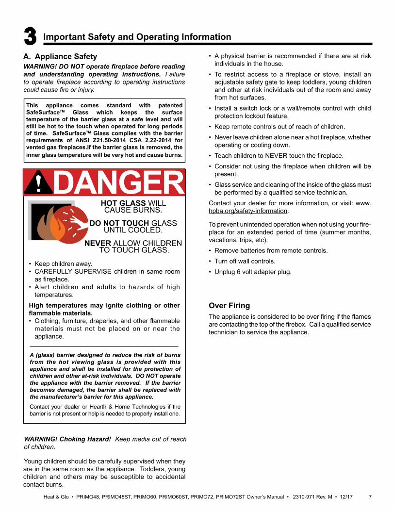
A (glass) barrier designed to reduce the risk of burns from the hot viewing glass is provided with this appliance and shall be installed for the protection of children and other at-risk individuals. DO NOT operate the appliance with the barrier removed. If the barrier becomes damaged, the barrier shall be replaced with the manufacturer’s barrier for this appliance. Contact your dealer or Hearth & Home Technologies if the barrier is not present or help is needed to properly install one.
DANGERHOT GLASS WILL CAUSE BURNS.
DO NOT TOUCH GLASS UNTIL COOLED.
NEVER ALLOW CHILDREN TO TOUCH GLASS.
• Keep children away.• CAREFULLY SUPERVISE children in same room
as fireplace.• Alert children and adults to hazards of high
temperatures.High temperatures may ignite clothing or other flammable materials.• Clothing, furniture, draperies, and other flammable
materials must not be placed on or near the appliance.
This appliance comes standard with patented SafeSurfaceTM Glass which keeps the surface temperature of the barrier glass at a safe level and will still be hot to the touch when operated for long periods of time. SafeSurfaceTM Glass complies with the barrier requirements of ANSI Z21.50-2014 CSA 2.22-2014 for vented gas fireplaces.If the barrier glass is removed, the inner glass temperature will be very hot and cause burns.
Heat & Glo • PRIMO48, PRIMO48ST, PRIMO60, PRIMO60ST, PRIMO72, PRIMO72ST Owner’s Manual • 2310-971 Rev. M • 12/17 8
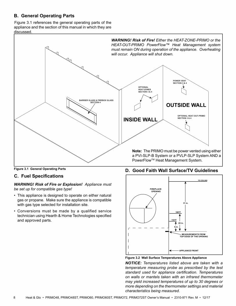
Figure 3.1 General Operating Parts
B. General Operating Parts
C. Fuel Specifications
WARNING! Risk of Fire or Explosion! Appliance must be set up for compatible gas type!• This appliance is designed to operate on either natural
gas or propane. Make sure the appliance is compatible with gas type selected for installation site.
• Conversions must be made by a qualified service technician using Hearth & Home Technologies specified and approved parts.
Figure 3.1 references the general operating parts of the appliance and the section of this manual in which they are discussed.
BARRIER GLASS & FIREBOX GLASS SECTION 4
OPTIONALHEAT-ZONESSECTION 3 & 4
OPTIONAL HEAT-OUT-PRIMOSECTION 3 & 4
POWER VENTSECTION 3 & 4
OUTSIDE WALL
INSIDE WALL
Figure 3.2 Wall Surface Temperatures Above Appliance
MEASUREMENTS FROMTOP EDGE OF THE OPENING
6 in.
TO CEILING
110°F
APPLIANCE FRONT
31 in.
FIREPLACE OPENING
100°F
20 in.
Note: The PRIMO must be power vented using either a PVI-SLP-B System or a PVLP-SLP System AND a PowerFlowTM Heat Management System.
WARNING! Risk of Fire! Either the HEAT-ZONE-PRIMO or the HEAT-OUT-PRIMO PowerFlow™ Heat Management system must remain ON during operation of the appliance. Overheating will occur. Appliance will shut down.
D. Good Faith Wall Surface/TV Guidelines
NOTICE: Temperatures listed above are taken with a temperature measuring probe as prescribed by the test standard used for appliance certification. Temperatures on walls or mantels taken with an infrared thermometer may yield increased temperatures of up to 30 degrees or more depending on the thermometer settings and material characteristics being measured.
9Heat & Glo • PRIMO48, PRIMO48ST, PRIMO60, PRIMO60ST, PRIMO72, PRIMO72ST Owner’s Manual • 2310-971 Rev. M • 12/17
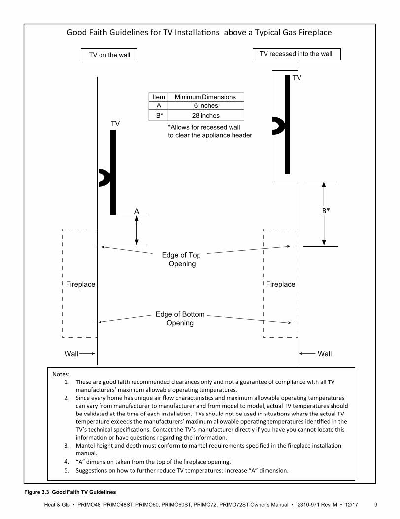
Good Faith Guidelines for TV Installations above a Typical Gas Fireplace
Fireplace
TV
A
Notes: 1. These are good faith recommended clearances only and not a guarantee of compliance with all TV
manufacturers’ maximum allowable operating temperatures. 2. Since every home has unique air flow characteristics and maximum allowable operating temperatures
can vary from manufacturer to manufacturer and from model to model, actual TV temperatures should be validated at the time of each installation. TVs should not be used in situations where the actual TV temperature exceeds the manufacturers’ maximum allowable operating temperatures identified in the TV’s technical specifications. Contact the TV’s manufacturer directly if you have you cannot locate this information or have questions regarding the information.
3. Mantel height and depth must conform to mantel requirements specified in the fireplace installation manual.
4. “A” dimension taken from the top of the fireplace opening. 5. Suggestions on how to further reduce TV temperatures:
Fireplace
B*
TV on the wall TV recessed into the wall
Edge of Top Opening
Edge of BottomOpening
Increase “A” dimension.
Wall Wall
Item Minimum DimensionsA 6 inches
28 inches B*
*Allows for recessed wallto clear the appliance header
TV
Figure 3.3 Good Faith TV Guidelines
Heat & Glo • PRIMO48, PRIMO48ST, PRIMO60, PRIMO60ST, PRIMO72, PRIMO72ST Owner’s Manual • 2310-971 Rev. M • 12/17 10
E. Before Lighting ApplianceBefore operating this fireplace for the first time, have a qualified service technician:• Verify all shipping materials have been removed from
inside and/or underneath the firebox.• Review proper placement of logs and media, if installed.• Check the wiring.• Check the air shutter adjustment.• Ensure that there are no gas leaks.• Ensure that the firebox glass is sealed and in the proper
position and that the integral glass barrier is in place.• Ensure the appliance is vented with the approved power
vent system: PVI-SLP-B or PVLP-SLP.• Ensure the appliance is equipped with HEAT-ZONE-
PRIMO and/or HEAT-OUT-PRIMO.• Barrier glass is installed properly with “THIS SIDE
OUT” text on outside. See Section 4.C.• Ensure there is a vertical gap of approximately 3/8 inch
between the bottom of the barrier glass and the transi-tion media tray for adequate air flow.
• Verify proper damper adjustment setting. See appli-ance installation manual.
WARNING! Risk of Fire or Asphyxiation! DO NOT op-erate fireplace with firebox glass assembly removed.
11Heat & Glo • PRIMO48, PRIMO48ST, PRIMO60, PRIMO60ST, PRIMO72, PRIMO72ST Owner’s Manual • 2310-971 Rev. M • 12/17
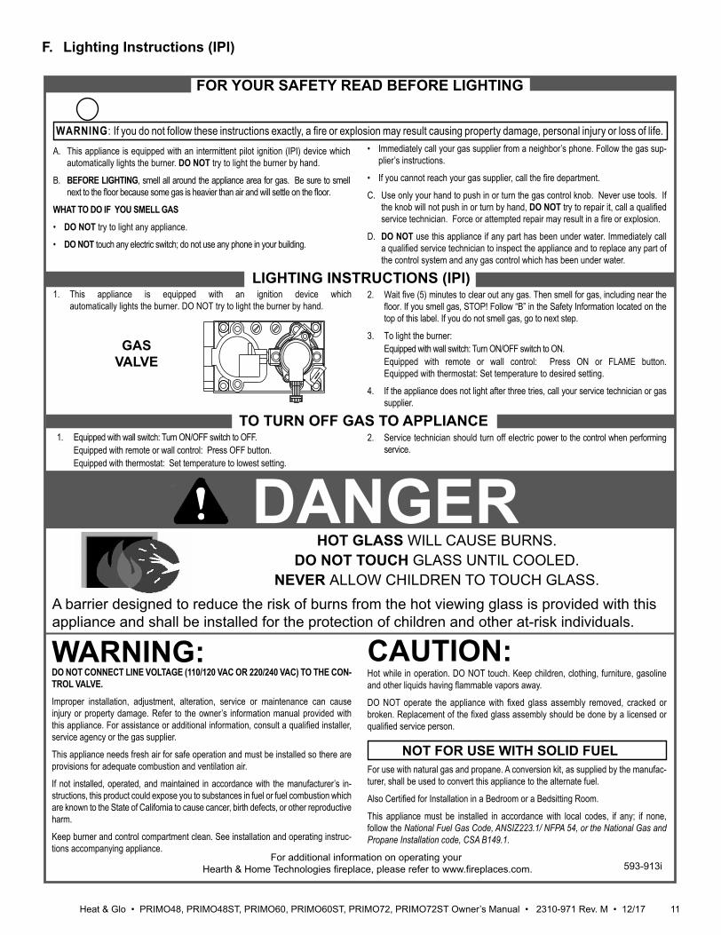
F. Lighting Instructions (IPI)
FOR YOUR SAFETY READ BEFORE LIGHTING
TO TURN OFF GAS TO APPLIANCE
1. This appliance is equipped with an ignition device whichautomatically lights the burner. DO NOT try to light the burner by hand.
1. Equipped with wall switch: Turn ON/OFF switch to OFF. Equipped with remote or wall control: Press OFF button. Equipped with thermostat: Set temperature to lowest setting.
WARNING: If you do not follow these instructions exactly, a fi re or explosion may result causing property damage, personal injury or loss of life.
WARNING:
NOT FOR USE WITH SOLID FUEL
GASVALVE
For additional information on operating your Hearth & Home Technologies fi replace, please refer to www.fi replaces.com.
A. This appliance is equipped with an intermittent pilot ignition (IPI) device which automatically lights the burner. DO NOT try to light the burner by hand.
B. BEFORE LIGHTING, smell all around the appliance area for gas. Be sure to smell next to the fl oor because some gas is heavier than air and will settle on the fl oor.
WHAT TO DO IF YOU SMELL GAS• DO NOT try to light any appliance.
• DO NOT touch any electric switch; do not use any phone in your building.
DO NOT CONNECT LINE VOLTAGE (110/120 VAC OR 220/240 VAC) TO THE CON-TROL VALVE.Improper installation, adjustment, alteration, service or maintenance can cause injury or property damage. Refer to the owner’s information manual provided with this appliance. For assistance or additional information, consult a qualifi ed installer, service agency or the gas supplier.
This appliance needs fresh air for safe operation and must be installed so there are provisions for adequate combustion and ventilation air.
If not installed, operated, and maintained in accordance with the manufacturer’s in-structions, this product could expose you to substances in fuel or fuel combustion which are known to the State of California to cause cancer, birth defects, or other reproductive harm.
Keep burner and control compartment clean. See installation and operating instruc-tions accompanying appliance.
Hot while in operation. DO NOT touch. Keep children, clothing, furniture, gasoline and other liquids having fl ammable vapors away.
DO NOT operate the appliance with fi xed glass assembly removed, cracked or broken. Replacement of the fi xed glass assembly should be done by a licensed or qualifi ed service person.
• Immediately call your gas supplier from a neighbor’s phone. Follow the gas sup-plier’s instructions.
• If you cannot reach your gas supplier, call the fi re department.
C. Use only your hand to push in or turn the gas control knob. Never use tools. If the knob will not push in or turn by hand, DO NOT try to repair it, call a qualifi ed service technician. Force or attempted repair may result in a fi re or explosion.
D. DO NOT use this appliance if any part has been under water. Immediately call a qualifi ed service technician to inspect the appliance and to replace any part of the control system and any gas control which has been under water.
For use with natural gas and propane. A conversion kit, as supplied by the manufac-turer, shall be used to convert this appliance to the alternate fuel.
Also Certifi ed for Installation in a Bedroom or a Bedsitting Room.
This appliance must be installed in accordance with local codes, if any; if none, follow the National Fuel Gas Code, ANSIZ223.1/ NFPA 54, or the National Gas and Propane Installation code, CSA B149.1.
LIGHTING INSTRUCTIONS (IPI)2. Wait fi ve (5) minutes to clear out any gas. Then smell for gas, including near the
fl oor. If you smell gas, STOP! Follow “B” in the Safety Information located on the top of this label. If you do not smell gas, go to next step.
3. To light the burner: Equipped with wall switch: Turn ON/OFF switch to ON. Equipped with remote or wall control: Press ON or FLAME button.
Equipped with thermostat: Set temperature to desired setting.
4. If the appliance does not light after three tries, call your service technician or gas supplier.
2. Service technician should turn off electric power to the control when performing service.
DANGERHOT GLASS WILL CAUSE BURNS.
DO NOT TOUCH GLASS UNTIL COOLED.NEVER ALLOW CHILDREN TO TOUCH GLASS.
CAUTION:
A barrier designed to reduce the risk of burns from the hot viewing glass is provided with this appliance and shall be installed for the protection of children and other at-risk individuals.
593-913i
Heat & Glo • PRIMO48, PRIMO48ST, PRIMO60, PRIMO60ST, PRIMO72, PRIMO72ST Owner’s Manual • 2310-971 Rev. M • 12/17 12
G. Appliance Break-InInitial Break-in Procedure• The fireplace should be run three to four hours
continuously on high.• Turn the fireplace off and allow it to completely cool.• Have a qualified service technician remove barrier glass
and firebox glass. See Section 4.• Have a qualified service technician clean firebox glass.
See Section 4.• Have a qualified service technician replace the barrier
glass and firebox glass. Run appliance continuously on high an additional 12 hours.
This cures the materials used to manufacture the fire-place.NOTICE! Open windows for air circulation during fire-place break-in.
• Some people may be sensitive to smoke and odors.• Smoke detectors may activate.
H. Heat ManagementBurn RateThe PRIMO models have a variable burn rate which is controlled by the remote control. Therefore the flame height is adjustable. The flame height may be adjusted as desired by locating the flame option on the remote control and adjusting up or down to desired flame height.
The PRIMO requires a PowerFlow™ Heat Management System. It may be either a HEAT-ZONE-PRIMO, which diverts heat into an adjacent room, and/or a HEAT-OUT-PRIMO which will divert heat outside the home/building.
HEAT-ZONE-PRIMOUse the optional HEAT-ZONE-PRIMO systems for heat management with the PRIMO. The HEAT-ZONE-PRIMO must be installed by a qualified service technician at the time of appliance installation. The PRIMO will not function properly unless the HEAT-ZONE-PRIMO systems are properly installed. HEAT-ZONE-PRIMO systems are designed to keep the barrier glass from overheating and to keep the controls and gas train cool.
HEAT-OUT-PRIMOUse the optional HEAT-OUT-PRIMO for heat manage-ment with the PRIMO. The HEAT-OUT-PRIMO allows the heat to be removed from the home while the fireplace is in operation. This feature is useful when heat is not needed,
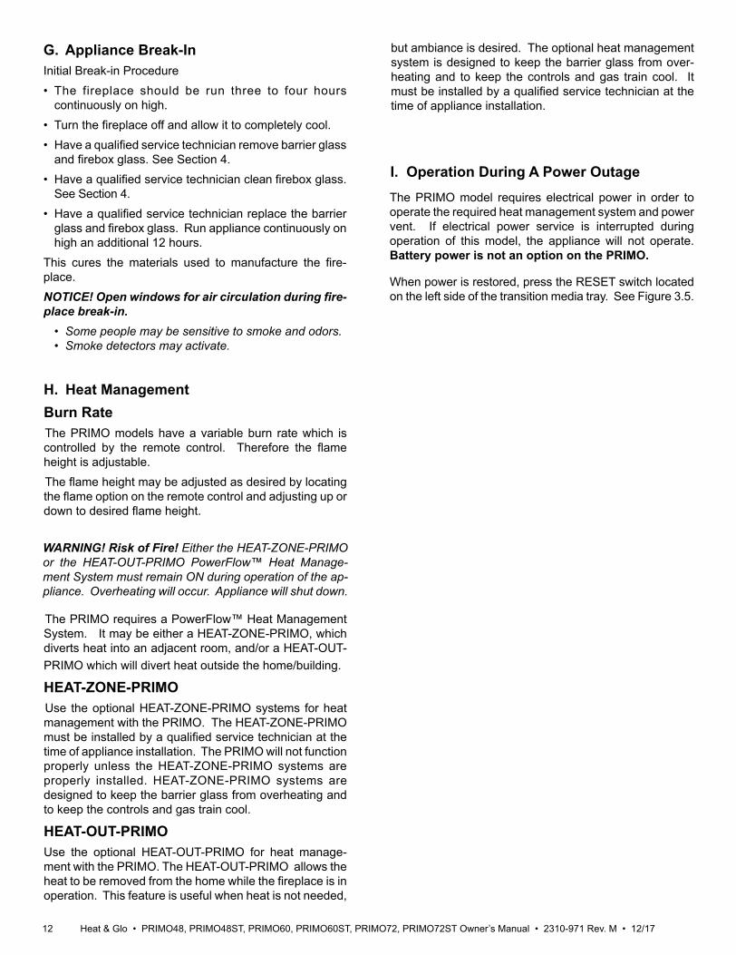
I. Operation During A Power Outage The PRIMO model requires electrical power in order to operate the required heat management system and power vent. If electrical power service is interrupted during operation of this model, the appliance will not operate. Battery power is not an option on the PRIMO.
When power is restored, press the RESET switch located on the left side of the transition media tray. See Figure 3.5.
WARNING! Risk of Fire! Either the HEAT-ZONE-PRIMO or the HEAT-OUT-PRIMO PowerFlow™ Heat Manage-ment System must remain ON during operation of the ap-pliance. Overheating will occur. Appliance will shut down.
but ambiance is desired. The optional heat management system is designed to keep the barrier glass from over-heating and to keep the controls and gas train cool. It must be installed by a qualified service technician at the time of appliance installation.
13Heat & Glo • PRIMO48, PRIMO48ST, PRIMO60, PRIMO60ST, PRIMO72, PRIMO72ST Owner’s Manual • 2310-971 Rev. M • 12/17
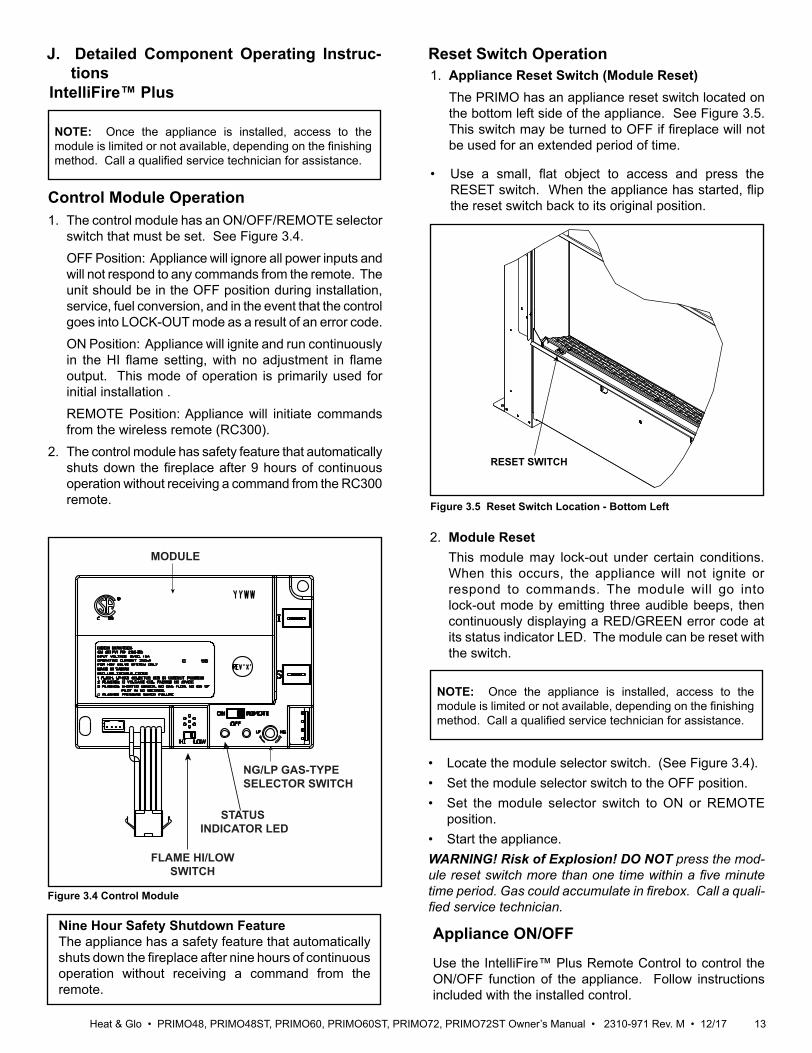
Figure 3.4 Control Module
Control Module Operation1. The control module has an ON/OFF/REMOTE selector
switch that must be set. See Figure 3.4. OFF Position: Appliance will ignore all power inputs and
will not respond to any commands from the remote. The unit should be in the OFF position during installation, service, fuel conversion, and in the event that the control goes into LOCK-OUT mode as a result of an error code.
ON Position: Appliance will ignite and run continuously in the HI flame setting, with no adjustment in flame output. This mode of operation is primarily used for initial installation .
REMOTE Position: Appliance will initiate commands from the wireless remote (RC300).
2. The control module has safety feature that automatically shuts down the fireplace after 9 hours of continuous operation without receiving a command from the RC300 remote.
2. Module Reset This module may lock-out under certain conditions.
When this occurs, the appliance will not ignite or respond to commands. The module will go into lock-out mode by emitting three audible beeps, then continuously displaying a RED/GREEN error code at its status indicator LED. The module can be reset with the switch.
Nine Hour Safety Shutdown FeatureThe appliance has a safety feature that automatically shuts down the fireplace after nine hours of continuous operation without receiving a command from the remote.
J. Detailed Component Operating Instruc-tions
Appliance ON/OFF
Use the IntelliFire™ Plus Remote Control to control the ON/OFF function of the appliance. Follow instructions included with the installed control.
IntelliFire™ Plus
NG/LP GAS-TYPESELECTOR SWITCH
FLAME HI/LOW SWITCH
STATUS INDICATOR LED
MODULE
Figure 3.5 Reset Switch Location - Bottom Left
RESET SWITCH
Reset Switch Operation1. Appliance Reset Switch (Module Reset) The PRIMO has an appliance reset switch located on
the bottom left side of the appliance. See Figure 3.5. This switch may be turned to OFF if fireplace will not be used for an extended period of time.
NOTE: Once the appliance is installed, access to the module is limited or not available, depending on the finishing method. Call a qualified service technician for assistance.
• Locate the module selector switch. (See Figure 3.4).• Set the module selector switch to the OFF position.• Set the module selector switch to ON or REMOTE
position.• Start the appliance.WARNING! Risk of Explosion! DO NOT press the mod-ule reset switch more than one time within a five minute time period. Gas could accumulate in firebox. Call a quali-fied service technician.
NOTE: Once the appliance is installed, access to the module is limited or not available, depending on the finishing method. Call a qualified service technician for assistance.
• Use a small, flat object to access and press the RESET switch. When the appliance has started, flip the reset switch back to its original position.
Heat & Glo • PRIMO48, PRIMO48ST, PRIMO60, PRIMO60ST, PRIMO72, PRIMO72ST Owner’s Manual • 2310-971 Rev. M • 12/17 14
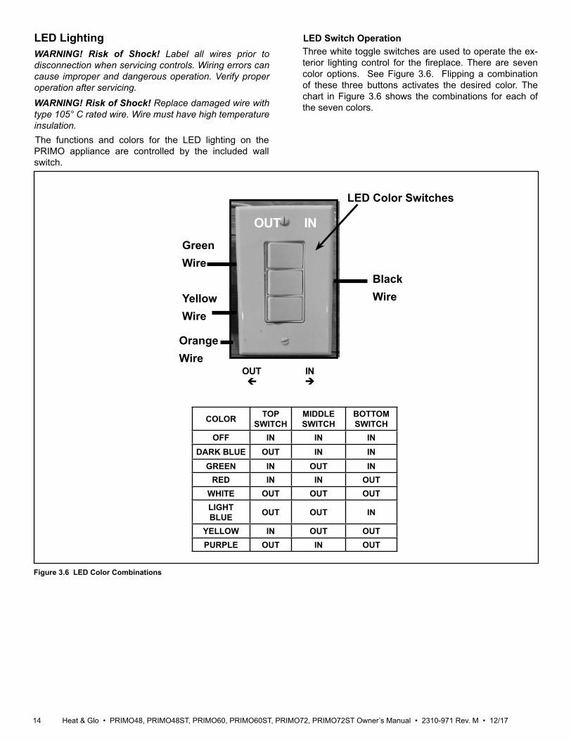
Figure 3.6 LED Color Combinations
LED Switch OperationThree white toggle switches are used to operate the ex-terior lighting control for the fireplace. There are seven color options. See Figure 3.6. Flipping a combination of these three buttons activates the desired color. The chart in Figure 3.6 shows the combinations for each of the seven colors.
OUT IN
OUT IN
Black Wire
GreenWire
OrangeWire
YellowWire
LED Color Switches
LED LightingWARNING! Risk of Shock! Label all wires prior to disconnection when servicing controls. Wiring errors can cause improper and dangerous operation. Verify proper operation after servicing.WARNING! Risk of Shock! Replace damaged wire with type 105° C rated wire. Wire must have high temperature insulation.The functions and colors for the LED lighting on the PRIMO appliance are controlled by the included wall switch.
COLOR TOP SWITCH
MIDDLE SWITCH
BOTTOM SWITCH
OFF IN IN INDARK BLUE OUT IN IN
GREEN IN OUT INRED IN IN OUT
WHITE OUT OUT OUTLIGHT BLUE OUT OUT IN
YELLOW IN OUT OUTPURPLE OUT IN OUT

15Heat & Glo • PRIMO48, PRIMO48ST, PRIMO60, PRIMO60ST, PRIMO72, PRIMO72ST Owner’s Manual • 2310-971 Rev. M • 12/17
HEAT-ZONE-PRIMOThe HEAT-ZONE-PRIMO is operated using a tempera-ture switch. When the appliance is turned on, the HEAT-ZONE-PRIMO will automatically turn on when the appli-ance stabilizes at its operating temperature. This process will take approximately 10-20 minutes.After a qualified service technician has installed the ap-pliance, including the Heat-Zones®, follow the instruction supplied with the appliance manual for operation. Contact your dealer if you have questions.
WARNING! Risk of Fire! Either the HEAT-ZONE-PRIMO or the HEAT-OUT-PRIMO must remain ON during opera-tion of the appliance. Overheating will occur. Appliance will shut down.
Wall Switch
HEAT-ZONE-PRIMO & HEAT-OUT-PRIMO Toggle
LED COLOR SWITCHES
Figure 3.7 PowerFlowTM Heat Management and LED Switch
HEAT-OUT-PRIMOThe HEAT-OUT-PRIMO is operated using a temperature switch. When the appliance is turned on, the HEAT-OUT-PRIMO will not turn on until the temperature switch has reached a predetermined temperature. This process will take approximately 10-20 minutes.After a qualified service technician has installed the ap-pliance, including the PowerFlow™ Heat Management system, follow the instructions supplied with the appliance manual for operation. Contact your dealer if you have questions.For additional information, see the instructions included with the HEAT-ZONE-PRIMO or HEAT-OUT-PRIMO product.
PowerFlow™ Heat Management System
The PRIMO requires a PowerFlow™ Heat Management System. It may be either a HEAT-ZONE-PRIMO, which diverts heat into an adjacent room, and/or HEAT-OUT-PRIMO which will divert heat outside the home/building.
Power Vent SystemPVI-SLP-B or PVLP-SLP
WARNING! Risk of Fire! PRIMO models must be power vented using PVI-SLP-B or PVLP-SLP. Failure to vent properly could cause overheating and fire.
A qualified service technician will install desired power vent system at the time of appliance installation. The PRIMO comes standard with a 2 minute pre-purge function designed to remove cold air and excess gas from the gas lines.The PRIMO comes standard with a 20 minute post-purge function designed to eliminate condensation in the venting system components.For additional information, see the instructions included with the power vent product.
Heat & Glo • PRIMO48, PRIMO48ST, PRIMO60, PRIMO60ST, PRIMO72, PRIMO72ST Owner’s Manual • 2310-971 Rev. M • 12/17 16
B. Maintenance Tasks: Homeowner
The following tasks may be performed annually by the homeowner. If you are uncomfortable performing any of the listed tasks, please call your dealer for a service ap-pointment.More frequent cleaning may be required due to lint from carpeting or other factors. Control compartment, burner and circulating air passageway of the fireplace must be kept clean.CAUTION! Risk of Burns! The fireplace should be turned off and cooled before servicing.
Any safety screen or guard removed for servicing must be replaced prior to operating the fireplace.
Installation and repair should be done by a qualified service technician only. The fireplace should be inspected before use and at least annually by a professional service person.
4 Maintenance and Service
Task Frequency To be completed by
Decorative Surrounds, Finishes Annually
Homeowner
Remote Control SeasonallyVenting SeasonallyHEAT-ZONE-PRIMO SeasonallyHEAT-OUT-PRIMO SeasonallyPower Vent Seasonally
Firebox Glass Cleaning Seasonally
Qualified Service Technician
Barrier Glass Cleaning SeasonallyGasket Seal and Glass Inspection Annually
Log Inspection Annually Firebox Inspection AnnuallyControl Compartment & Firebox Top Annually
Burner Ignition & Operation Annually
A. Maintenance: Frequency and TasksThe matrix below is an overview of maintenance tasks to be performed on the appliance. Sections B and C give details and instructions needed to assist the appropriate person in performing the tasks.
When properly maintained, your fireplace will give you many years of trouble-free service. Contact your dealer to answer questions regarding proper operation, trou-bleshooting and service for your appliance. Visit www.heatnglo.com to locate a dealer. We recommend annual service by a qualified service technician.
Decorative Surrounds, FinishesFrequency: AnnuallyBy: HomeownerTools needed: Protective gloves • Inspect for scratches, dents or other damage. Call a
qualified service technician for assistance if any damage is found.
• Verify the 3/8 in. gap between barrier glass and transition media tray is not blocked.
• Dust barrier glass and finishing material.
Remote ControlFrequency: SeasonallyBy: HomeownerTools needed: Replacement batteries and remote con-trol instructions.• Locate and verify operation of remote. Refer to remote
control operation instructions for proper calibration and setup procedure.
• Place batteries as needed in remote.• Place remote control out of reach of children.If not using your fireplace for an extended period of time (summer months, vacations/trips, etc), to prevent unin-tended operation:• Remove batteries from remote controls.• Turn reset switch to off.
17Heat & Glo • PRIMO48, PRIMO48ST, PRIMO60, PRIMO60ST, PRIMO72, PRIMO72ST Owner’s Manual • 2310-971 Rev. M • 12/17
HEAT-ZONE-PRIMOFrequency: SeasonallyBy: HomeownerTools Needed: Protective gloves and safety glasses.• Inspect venting and air register(s) clean and free of any
blockage or obstructions.• Verify fan is working properly.
HEAT-OUT-PRIMOFrequency: SeasonallyBy: HomeownerTools Needed: Protective gloves and safety glasses.• Inspect venting and termination cap for blockage or
obstructions inside such plants, bird nests, leaves, snow, debris, etc.
• Verify termination cap clearance to subsequent construc-tion (building additions, decks, fences, or sheds).
• Verify fan is working properly.
Power Vent SystemFrequency: SeasonallyBy: HomeownerTools Needed: Protective gloves and safety glasses.• Inspect venting and termination cap for blockage or
obstruction such plants, bird nests, leaves, snow, debris, etc.
• Verify termination cap clearance to subsequent construc-tion (building additions, decks, fences, or sheds).
• Verify fan is working properly.
WARNING! Risk of Shock! Before performing any main-tenance or repair to the power vent assembly, make sure electrical power to the fireplace is disconnected.• Access Panel: Inspect at least annually. Ensure vertical
gap, located between transition media tray and bottom edge of the barrier glass, is free of dust and debris.
VentingFrequency: SeasonallyBy: HomeownerTools needed: Protective gloves and safety glasses.• Inspect venting and termination cap for blockage or
obstruction such plants, bird nests, leaves, snow, debris, etc.
• Verify termination cap clearance to subsequent construc-tion (building additions, decks, fences, or sheds).
• Inspect for corrosion or separation.• Verify weather stripping, sealing and flashing remains
intact.• Inspect draft shield to verify it is not damaged or missing.
Note: The PRIMO must be power-vented using either a PVI-SLP-B system or a PVLP-SLP system.
WARNING! Risk of Fire! Either the HEAT-ZONE-PRIMO or the HEAT-OUT-PRIMO must remain ON during opera-tion of the appliance. Overheating will occur. Appliance will shut down.
PowerFlow™ Heat Management System
Heat & Glo • PRIMO48, PRIMO48ST, PRIMO60, PRIMO60ST, PRIMO72, PRIMO72ST Owner’s Manual • 2310-971 Rev. M • 12/17 18
C. Maintenance Tasks: Qualified Service Technician
The following tasks must be performed by a qualified ser-vice technician.
Glass CleaningFrequency: SeasonallyBy: Qualified Service TechnicianTools Needed: Protective gloves, glass cleaner, suction cups, drop cloth and a stable work surface.WARNING! Risk of Asphyxiation! Handle firebox glass assembly with care. Inspect the gasket to ensure it is undamaged and inspect the glass for cracks, chips or scratches. • DO NOT strike, slam or scratch glass.• DO NOT operate fireplace with glass removed, cracked,
broken or scratched.• Replace as a complete assembly.CAUTION! Risk of Injury! Glass assembly installation and removal must be performed by a qualified service technician. See chart below for glass assembly weights.• PRIMO60 AND PRIMO72 MODELS: It is recom-
mended that Glass installation and removal be per-formed by two qualified service technicians.
CAUTION! Risk of Cuts or Abrasions. Wear protective gloves and safety glasses during installation. Sheet metal edges are sharp.
WARNING! Risk of Injury! Glass is heavy. Use suction cups to handle glass.
WARNING! Handle glass with care. Glass is breakable. Inspect the gasket to ensure it is undamaged and inspect the glass for cracks, chips or scratches.
• Avoid striking, scratching or slamming glass.• Avoid abrasive cleaners.• DO NOT clean glass while it is hot.
• Replace as a complete assembly.• Prepare a work area large enough to accommodate
firebox glass assembly and barrier glass by placing a drop cloth on a flat, stable surface.
Note: Firebox glass assembly and gasketing may have residue that can stain carpeting or floor surfaces.
Cleaning Barrier Glass and Firebox Glass• See below for proper glass removal instructions.• Clean glass with a non-abrasive commercially avail-
able cleaner.- Light deposits: Use a soft cloth with soap and water.- Heavy deposits: Use commercial fireplace glass
cleaner (consult with your dealer).
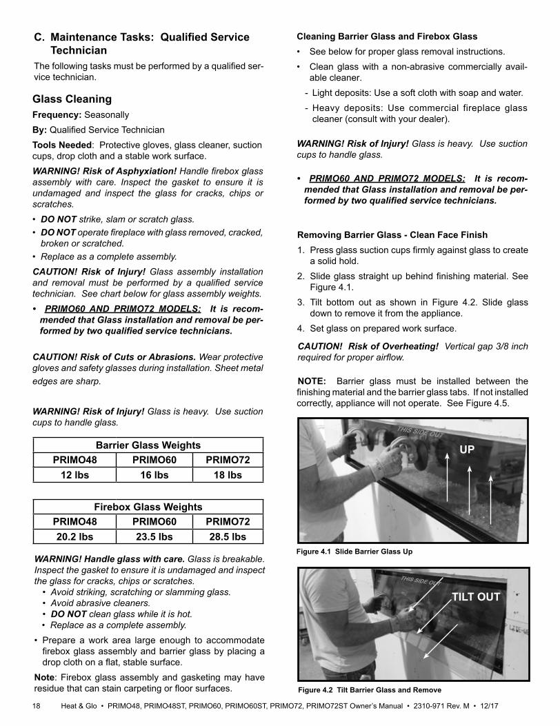
Figure 4.1 Slide Barrier Glass Up
Figure 4.2 Tilt Barrier Glass and Remove
Barrier Glass WeightsPRIMO48 PRIMO60 PRIMO72
12 lbs 16 lbs 18 lbs
UP
TILT OUT
WARNING! Risk of Injury! Glass is heavy. Use suction cups to handle glass.
Removing Barrier Glass - Clean Face Finish1. Press glass suction cups firmly against glass to create
a solid hold. 2. Slide glass straight up behind finishing material. See
Figure 4.1.3. Tilt bottom out as shown in Figure 4.2. Slide glass
down to remove it from the appliance.4. Set glass on prepared work surface.
Firebox Glass WeightsPRIMO48 PRIMO60 PRIMO7220.2 lbs 23.5 lbs 28.5 lbs
• PRIMO60 AND PRIMO72 MODELS: It is recom-mended that Glass installation and removal be per-formed by two qualified service technicians.
CAUTION! Risk of Overheating! Vertical gap 3/8 inch required for proper airflow.
THIS SIDE OUT
THIS SIDE OUT
NOTE: Barrier glass must be installed between the finishing material and the barrier glass tabs. If not installed correctly, appliance will not operate. See Figure 4.5.

19Heat & Glo • PRIMO48, PRIMO48ST, PRIMO60, PRIMO60ST, PRIMO72, PRIMO72ST Owner’s Manual • 2310-971 Rev. M • 12/17
Figure 4.3 Remove Barrier Glass - Black Granite Finish
BARRIER GLASS
GLASS SUPPORT BRACKET
D-SHAPED RETAINING TAB
THIS
SID
E OU
TTH
IS S
IDE
OUT
NOTE: INSTALL BARRIER GLASS PRINTED SIDE OUT.“THIS SIDE OUT” MUST BE LEGIBLE ON BARRIER GLASS.
GLASS GASKET BULB LOCATED BEHIND GRANITE
Removing Barrier Glass - Black Granite Finish 1. Slide side granite pieces inward toward center of fire-
place to disengage from the key slots. See appliance installation manual.
2. Remove (unscrew) D-shaped retaining tabs.3. The glass rests against the barrier glass support
bracket. See Figure 4.3.4. Use suction cups to remove barrier glass.5. Rotate/tilt the bottom of the glass outward to remove.
See Figure 4.2.6. Set the glass on a prepared work surface.
Figure 4.4 Glass Gasket Detail - Black Granite Finish
GLASS GASKET BULB
TOP
BOTTOM
Figure 4.5 Replace Barrier Glass - Clean Face Finish
BARRIER GLASS TABS
THIS SIDE OUT
NOTE: INSTALL BARRIER GLASS PRINTED SIDE OUT.“THIS SIDE OUT” MUST BE LEGIBLE ON BARRIER GLASS.
3/8 IN. VERTICAL
GAP REQUIRED
Heat & Glo • PRIMO48, PRIMO48ST, PRIMO60, PRIMO60ST, PRIMO72, PRIMO72ST Owner’s Manual • 2310-971 Rev. M • 12/17 20
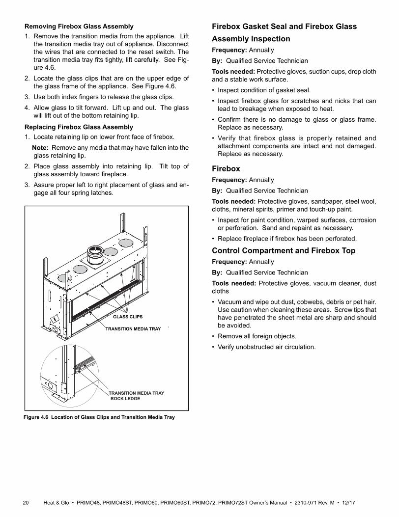
Removing Firebox Glass Assembly1. Remove the transition media from the appliance. Lift
the transition media tray out of appliance. Disconnect the wires that are connected to the reset switch. The transition media tray fits tightly, lift carefully. See Fig-ure 4.6.
2. Locate the glass clips that are on the upper edge of the glass frame of the appliance. See Figure 4.6.
3. Use both index fingers to release the glass clips. 4. Allow glass to tilt forward. Lift up and out. The glass
will lift out of the bottom retaining lip.
Replacing Firebox Glass Assembly1. Locate retaining lip on lower front face of firebox. Note: Remove any media that may have fallen into the
glass retaining lip.2. Place glass assembly into retaining lip. Tilt top of
glass assembly toward fireplace.3. Assure proper left to right placement of glass and en-
gage all four spring latches.
Figure 4.6 Location of Glass Clips and Transition Media Tray
GLASS CLIPS
TRANSITION MEDIA TRAY
TRANSITION MEDIA TRAYROCK LEDGE
Firebox Gasket Seal and Firebox Glass Assembly InspectionFrequency: AnnuallyBy: Qualified Service TechnicianTools needed: Protective gloves, suction cups, drop cloth and a stable work surface.• Inspect condition of gasket seal.• Inspect firebox glass for scratches and nicks that can
lead to breakage when exposed to heat. • Confirm there is no damage to glass or glass frame.
Replace as necessary.• Verify that firebox glass is properly retained and
attachment components are intact and not damaged. Replace as necessary.
FireboxFrequency: AnnuallyBy: Qualified Service TechnicianTools needed: Protective gloves, sandpaper, steel wool, cloths, mineral spirits, primer and touch-up paint.• Inspect for paint condition, warped surfaces, corrosion
or perforation. Sand and repaint as necessary.• Replace fireplace if firebox has been perforated.
Control Compartment and Firebox TopFrequency: AnnuallyBy: Qualified Service TechnicianTools needed: Protective gloves, vacuum cleaner, dust cloths• Vacuum and wipe out dust, cobwebs, debris or pet hair.
Use caution when cleaning these areas. Screw tips that have penetrated the sheet metal are sharp and should be avoided.
• Remove all foreign objects.• Verify unobstructed air circulation.
21Heat & Glo • PRIMO48, PRIMO48ST, PRIMO60, PRIMO60ST, PRIMO72, PRIMO72ST Owner’s Manual • 2310-971 Rev. M • 12/17
Burner Ignition and OperationFrequency: AnnuallyBy: Qualified Service TechnicianTools needed: Protective gloves, vacuum cleaner, whisk broom, flashlight, voltmeter, indexed drill bit set, and a manometer.• Verify burner is properly secured and aligned with pilot
or igniter.• Clean off burner tube, inspect for plugged ports, corrosion
or deterioration. Replace burner if necessary.• Inspect for lifting or other flame problems.• Verify air shutter setting is correct. See Installation
Manual for required air shutter setting. Verify air shutter is clear of dust and debris.
• Inspect orifice for soot, dirt and corrosion. Verify orifice size is correct. See Service Parts List for proper orifice sizing.
• Verify manifold and inlet pressures. Adjust regulator as required.
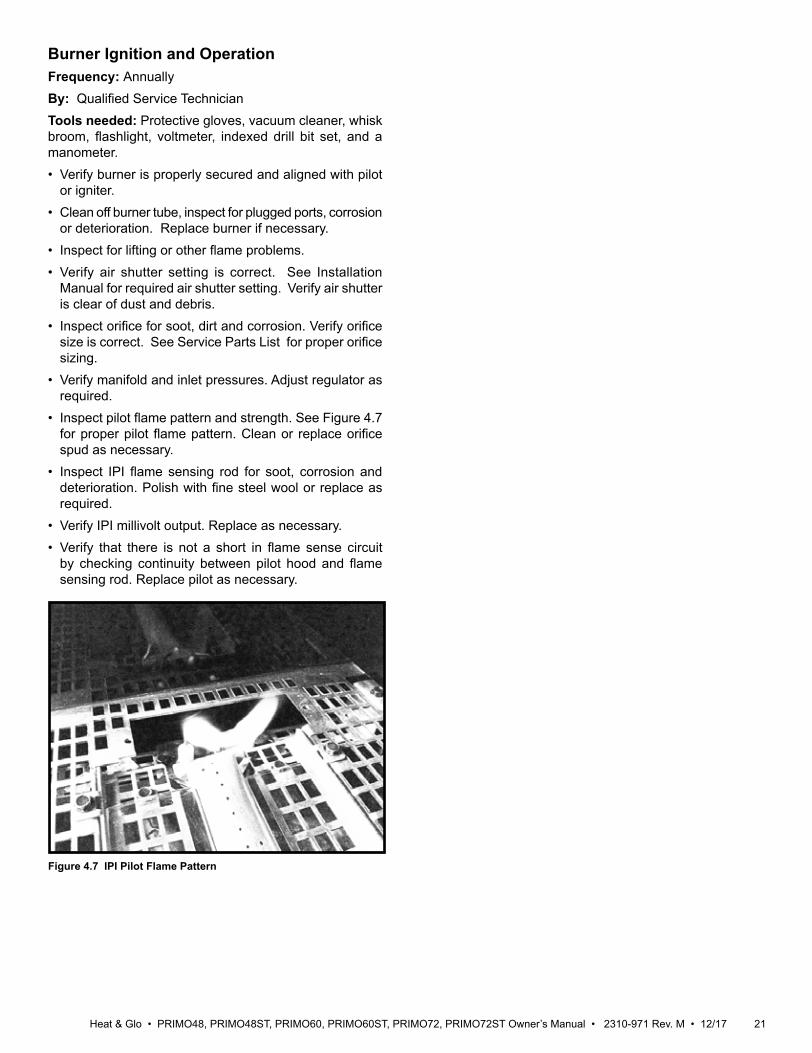
• Inspect pilot flame pattern and strength. See Figure 4.7 for proper pilot flame pattern. Clean or replace orifice spud as necessary.
• Inspect IPI flame sensing rod for soot, corrosion and deterioration. Polish with fine steel wool or replace as required.
• Verify IPI millivolt output. Replace as necessary.• Verify that there is not a short in flame sense circuit
by checking continuity between pilot hood and flame sensing rod. Replace pilot as necessary.
Figure 4.7 IPI Pilot Flame Pattern
Heat & Glo • PRIMO48, PRIMO48ST, PRIMO60, PRIMO60ST, PRIMO72, PRIMO72ST Owner’s Manual • 2310-971 Rev. M • 12/17 22
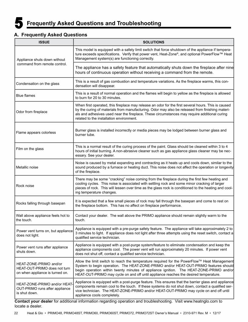
5 Frequently Asked Questions and Troubleshooting
A. Frequently Asked QuestionsISSUE SOLUTIONS
Appliance shuts down without command from remote control.
This model is equipped with a safety limit switch that force shutdown of the appliance if tempera-ture exceeds specifications. Verify that power vent, Heat-Zone®, and optional PowerFlow™ Heat Management system(s) are functioning correctly.
The appliance has a safety feature that automatically shuts down the fireplace after nine hours of continuous operation without receiving a command from the remote.
Condensation on the glass This is a result of gas combustion and temperature variations. As the fireplace warms, this con-densation will disappear.
Blue flames This is a result of normal operation and the flames will begin to yellow as the fireplace is allowed to burn for 20 to 30 minutes.
Odor from fireplace
When first operated, this fireplace may release an odor for the first several hours. This is caused by the curing of materials from manufacturing. Odor may also be released from finishing materi-als and adhesives used near the fireplace. These circumstances may require additional curing related to the installation environment.
Flame appears colorless Burner glass is installed incorrectly or media pieces may be lodged between burner glass and burner tube.
Film on the glass This is a normal result of the curing process of the paint. Glass should be cleaned within 3 to 4 hours of initial burning. A non-abrasive cleaner such as gas appliance glass cleaner may be nec-essary. See your dealer.
Metallic noiseNoise is caused by metal expanding and contracting as it heats up and cools down, similar to the sound produced by a furnace or heating duct. This noise does not affect the operation or longevity of the fireplace.
Rock noise
There may be some “cracking” noise coming from the fireplace during the first few heating and cooling cycles. This noise is associated with settling rock and some minor cracking of larger pieces of rock. This will lessen over time as the glass rock is conditioned to the heating and cool-ing temperature changes.
Rocks falling through basepan It is expected that a few small pieces of rock may fall through the basepan and come to rest on the fireplace bottom. This has no affect on fireplace performance.
Wall above appliance feels hot to the touch.
Contact your dealer. The wall above the PRIMO appliance should remain slightly warm to the touch.
Power vent turns on, but appliance does not light.
Appliance is equipped with a pre-purge safety feature. The appliance will take approximately 2 to 3 minutes to light. If appliance does not light after three attempts using the reset switch, contact a qualified service technician.
Power vent runs after appliance shuts down.
Appliance is equipped with a post-purge system/feature to eliminate condensation and keep the appliance components cool. The power vent will run approximately 20 minutes. If power vent does not shut off, contact a qualified service technician.
HEAT-ZONE-PRIMO and/or HEAT-OUT-PRIMO does not turn on when appliance is turned on.
Allow the limit switch to reach the temperature required for the PowerFlowTM Heat Management System to begin operation. The HEAT-ZONE-PRIMO and/or HEAT-OUT-PRIMO features should begin operation within twenty minutes of appliance ignition. The HEAT-ZONE-PRIMO and/or HEAT-OUT-PRIMO may cycle on and off until appliance reaches the desired temperature.
HEAT-ZONE-PRIMO and/or HEAT-OUT-PRIMO runs after appliance is shut down.
Appliance is equipped with a post-purge feature. This ensures that the barrier glass and appliance components remain cool to the touch. If these systems do not shut down, contact a qualified ser-vice technician. The HEAT-ZONE-PRIMO and/or HEAT-OUT-PRIMO may cycle on and off until appliance cools completely.
Contact your dealer for additional information regarding operation and troubleshooting. Visit www.heatnglo.com to locate a dealer.
23Heat & Glo • PRIMO48, PRIMO48ST, PRIMO60, PRIMO60ST, PRIMO72, PRIMO72ST Owner’s Manual • 2310-971 Rev. M • 12/17
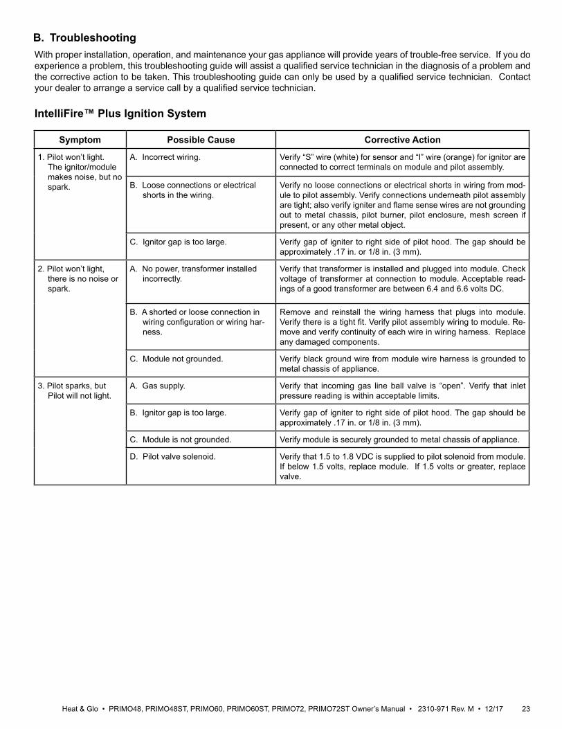
With proper installation, operation, and maintenance your gas appliance will provide years of trouble-free service. If you do experience a problem, this troubleshooting guide will assist a qualified service technician in the diagnosis of a problem and the corrective action to be taken. This troubleshooting guide can only be used by a qualified service technician. Contact your dealer to arrange a service call by a qualified service technician.
B. Troubleshooting
IntelliFire™ Plus Ignition System
Symptom Possible Cause Corrective Action
1. Pilot won’t light. The ignitor/module makes noise, but no spark.
A. Incorrect wiring. Verify “S” wire (white) for sensor and “I” wire (orange) for ignitor are connected to correct terminals on module and pilot assembly.
B. Loose connections or electrical shorts in the wiring.
Verify no loose connections or electrical shorts in wiring from mod-ule to pilot assembly. Verify connections underneath pilot assembly are tight; also verify igniter and flame sense wires are not grounding out to metal chassis, pilot burner, pilot enclosure, mesh screen if present, or any other metal object.
C. Ignitor gap is too large. Verify gap of igniter to right side of pilot hood. The gap should be approximately .17 in. or 1/8 in. (3 mm).
2. Pilot won’t light, there is no noise or spark.
A. No power, transformer installed incorrectly.
Verify that transformer is installed and plugged into module. Check voltage of transformer at connection to module. Acceptable read-ings of a good transformer are between 6.4 and 6.6 volts DC.
B. A shorted or loose connection in wiring configuration or wiring har-ness.
Remove and reinstall the wiring harness that plugs into module. Verify there is a tight fit. Verify pilot assembly wiring to module. Re-move and verify continuity of each wire in wiring harness. Replace any damaged components.
C. Module not grounded. Verify black ground wire from module wire harness is grounded to metal chassis of appliance.
3. Pilot sparks, but Pilot will not light.
A. Gas supply. Verify that incoming gas line ball valve is “open”. Verify that inlet pressure reading is within acceptable limits.
B. Ignitor gap is too large. Verify gap of igniter to right side of pilot hood. The gap should be approximately .17 in. or 1/8 in. (3 mm).
C. Module is not grounded. Verify module is securely grounded to metal chassis of appliance.
D. Pilot valve solenoid. Verify that 1.5 to 1.8 VDC is supplied to pilot solenoid from module. If below 1.5 volts, replace module. If 1.5 volts or greater, replace valve.
Heat & Glo • PRIMO48, PRIMO48ST, PRIMO60, PRIMO60ST, PRIMO72, PRIMO72ST Owner’s Manual • 2310-971 Rev. M • 12/17 24
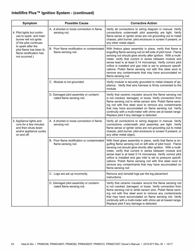
Intellifire Plus™ Ignition System - (continued)
Symptom Possible Cause Corrective Action
4. Pilot lights but contin-ues to spark, and main burner will not ignite. (If the pilot continues to spark after the pilot flame has been lit, flame rectification has not occurred.)
A. A shorted or loose connection in flame sensing rod.
Verify all connections to wiring diagram in manual. Verify connections underneath pilot assembly are tight. Verify flame sense or igniter wires are not grounding out to metal chassis, pilot burner, pilot enclosure or screen if present, or any other metal object.
B. Poor flame rectification or contaminated flame sensing rod.
With firebox glass assembly in place, verify that flame is engulfing flame sensing rod on left side of pilot hood. Flame sensing rod should glow shortly after ignition. With a multi-meter, verify that current in series between module and sense lead is at least 0.14 microamps. Verify correct pilot orifice is installed and gas inlet is set to pressure specifi-cations. Polish flame sensing rod with fine steel wool to remove any contaminants that may have accumulated on flame sensing rod.
C. Module is not grounded. Verify module is securely grounded to metal chassis of ap-pliance. Verify that wire harness is firmly connected to the module.
D. Damaged pilot assembly or contami-nated flame sensing rod.
Verify that ceramic insulator around the flame sensing rod is not cracked, damaged, or loose. Verify connection from flame sensing rod to white sensor wire. Polish flame sens-ing rod with fine steel wool to remove any contaminants that may have accumulated on flame sensing rod. Verify continuity with a multi-meter with ohms set at lowest range. Replace pilot if any damage is detected.
5. Appliance lights and runs for a few minutes and then shuts down and/or appliance cycles on and off.
A. A shorted or loose connection in flame sensing rod.
Verify all connections to wiring diagram in manual. Verify connections underneath pilot assembly are tight. Verify flame sense or igniter wires are not grounding out to metal chassis, pilot burner, pilot enclosure or screen if present, or any other metal object.
B. Poor flame rectification or contaminated flame sensing rod.
With fixed glass assembly in place, verify that flame is en-gulfing flame sensing rod on left side of pilot hood. Flame sensing rod should glow shortly after ignition. With a multi-meter, verify that current in series between module and sense lead is at least 0.14 microamps. Verify correct pilot orifice is installed and gas inlet is set to pressure specifi-cations. Polish flame sensing rod with fine steel wool to remove any contaminants that may have accumulated on flame sensing rod.
C. Logs are set up incorrectly. Remove and reinstall logs per the log placement instructions.
D. Damaged pilot assembly or contami-nated flame sensing rod.
Verify that ceramic insulator around the flame sensing rod is not cracked, damaged, or loose. Verify connection from flame sensing rod to white sensor wire. Polish flame sens-ing rod with fine steel wool to remove any contaminants that may have accumulated on flame sensing rod. Verify continuity with a multi-meter with ohms set at lowest range. Replace pilot if any damage is detected.
25Heat & Glo • PRIMO48, PRIMO48ST, PRIMO60, PRIMO60ST, PRIMO72, PRIMO72ST Owner’s Manual • 2310-971 Rev. M • 12/17
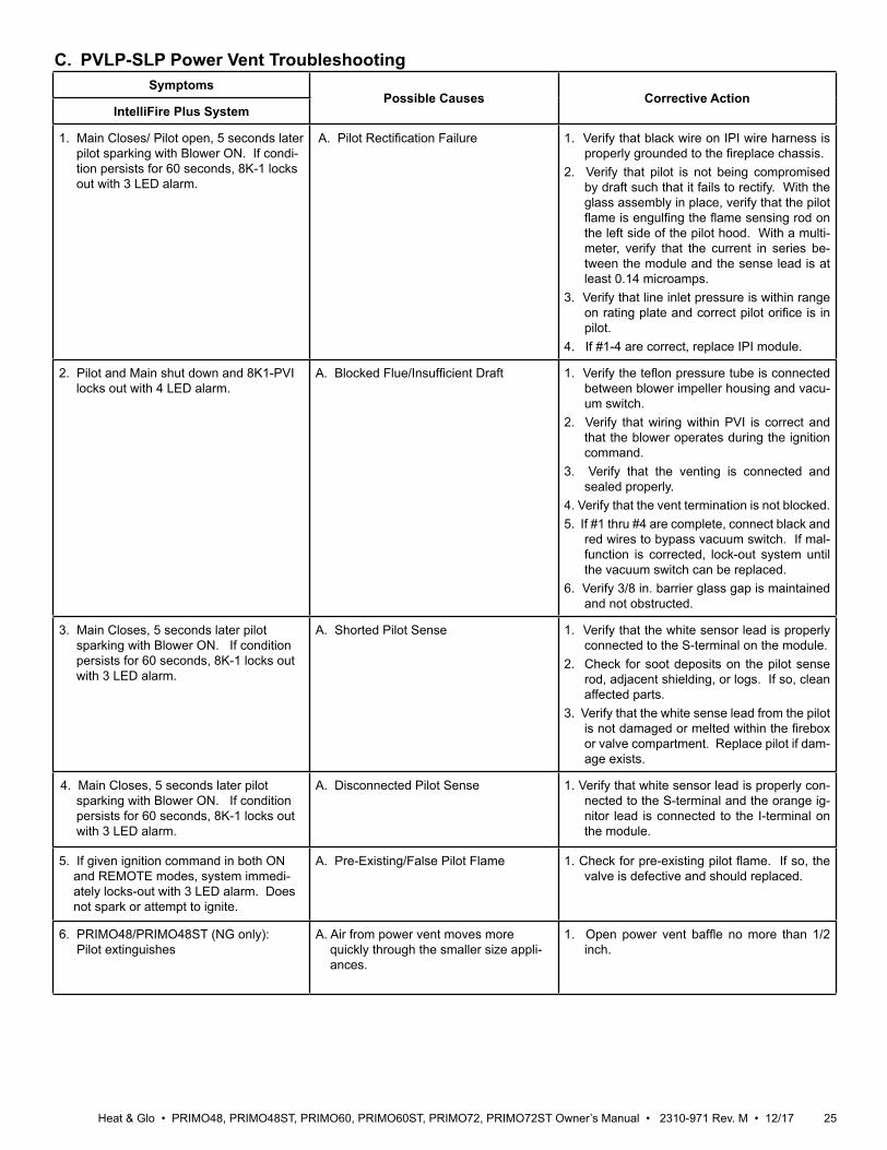
C. PVLP-SLP Power Vent TroubleshootingSymptoms
Possible Causes Corrective ActionIntelliFire Plus System
1. Main Closes/ Pilot open, 5 seconds later pilot sparking with Blower ON. If condi-tion persists for 60 seconds, 8K-1 locks out with 3 LED alarm.
A. Pilot Rectification Failure 1. Verify that black wire on IPI wire harness is properly grounded to the fireplace chassis.
2. Verify that pilot is not being compromised by draft such that it fails to rectify. With the glass assembly in place, verify that the pilot flame is engulfing the flame sensing rod on the left side of the pilot hood. With a multi-meter, verify that the current in series be-tween the module and the sense lead is at least 0.14 microamps.
3. Verify that line inlet pressure is within range on rating plate and correct pilot orifice is in pilot.
4. If #1-4 are correct, replace IPI module.
2. Pilot and Main shut down and 8K1-PVI locks out with 4 LED alarm.
A. Blocked Flue/Insufficient Draft 1. Verify the teflon pressure tube is connected between blower impeller housing and vacu-um switch.
2. Verify that wiring within PVI is correct and that the blower operates during the ignition command.
3. Verify that the venting is connected and sealed properly.
4. Verify that the vent termination is not blocked. 5. If #1 thru #4 are complete, connect black and
red wires to bypass vacuum switch. If mal-function is corrected, lock-out system until the vacuum switch can be replaced.
6. Verify 3/8 in. barrier glass gap is maintained and not obstructed.
3. Main Closes, 5 seconds later pilot sparking with Blower ON. If condition persists for 60 seconds, 8K-1 locks out with 3 LED alarm.
A. Shorted Pilot Sense 1. Verify that the white sensor lead is properly connected to the S-terminal on the module.
2. Check for soot deposits on the pilot sense rod, adjacent shielding, or logs. If so, clean affected parts.
3. Verify that the white sense lead from the pilot is not damaged or melted within the firebox or valve compartment. Replace pilot if dam-age exists.
4. Main Closes, 5 seconds later pilot sparking with Blower ON. If condition persists for 60 seconds, 8K-1 locks out with 3 LED alarm.
A. Disconnected Pilot Sense 1. Verify that white sensor lead is properly con-nected to the S-terminal and the orange ig-nitor lead is connected to the I-terminal on the module.
5. If given ignition command in both ON and REMOTE modes, system immedi-ately locks-out with 3 LED alarm. Does not spark or attempt to ignite.
A. Pre-Existing/False Pilot Flame 1. Check for pre-existing pilot flame. If so, the valve is defective and should replaced.
6. PRIMO48/PRIMO48ST (NG only): Pilot extinguishes
A. Air from power vent moves more quickly through the smaller size appli-ances.
1. Open power vent baffle no more than 1/2 inch.
Heat & Glo • PRIMO48, PRIMO48ST, PRIMO60, PRIMO60ST, PRIMO72, PRIMO72ST Owner’s Manual • 2310-971 Rev. M • 12/17 26
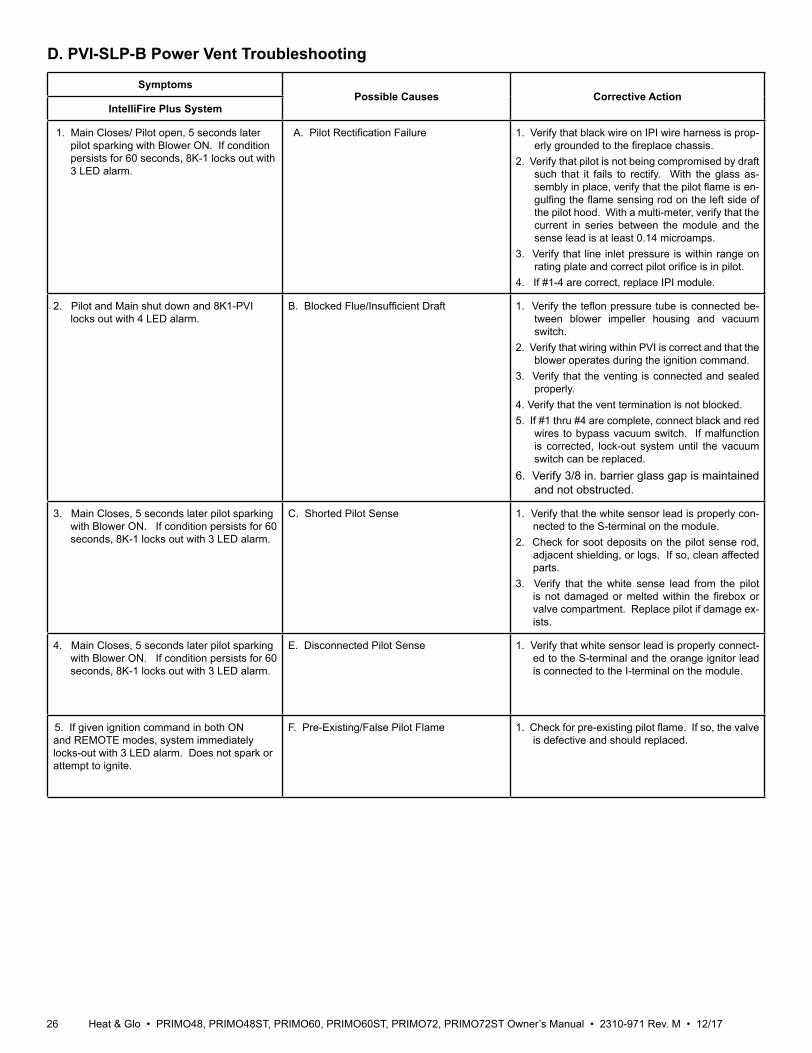
SymptomsPossible Causes Corrective Action
IntelliFire Plus System
1. Main Closes/ Pilot open, 5 seconds later pilot sparking with Blower ON. If condition persists for 60 seconds, 8K-1 locks out with 3 LED alarm.
A. Pilot Rectification Failure 1. Verify that black wire on IPI wire harness is prop-erly grounded to the fireplace chassis.
2. Verify that pilot is not being compromised by draft such that it fails to rectify. With the glass as-sembly in place, verify that the pilot flame is en-gulfing the flame sensing rod on the left side of the pilot hood. With a multi-meter, verify that the current in series between the module and the sense lead is at least 0.14 microamps.
3. Verify that line inlet pressure is within range on rating plate and correct pilot orifice is in pilot.
4. If #1-4 are correct, replace IPI module.
2. Pilot and Main shut down and 8K1-PVI locks out with 4 LED alarm.
B. Blocked Flue/Insufficient Draft 1. Verify the teflon pressure tube is connected be-tween blower impeller housing and vacuum switch.
2. Verify that wiring within PVI is correct and that the blower operates during the ignition command.
3. Verify that the venting is connected and sealed properly.
4. Verify that the vent termination is not blocked. 5. If #1 thru #4 are complete, connect black and red
wires to bypass vacuum switch. If malfunction is corrected, lock-out system until the vacuum switch can be replaced.
6. Verify 3/8 in. barrier glass gap is maintained and not obstructed.
3. Main Closes, 5 seconds later pilot sparking with Blower ON. If condition persists for 60 seconds, 8K-1 locks out with 3 LED alarm.
C. Shorted Pilot Sense 1. Verify that the white sensor lead is properly con-nected to the S-terminal on the module.
2. Check for soot deposits on the pilot sense rod, adjacent shielding, or logs. If so, clean affected parts.
3. Verify that the white sense lead from the pilot is not damaged or melted within the firebox or valve compartment. Replace pilot if damage ex-ists.
4. Main Closes, 5 seconds later pilot sparking with Blower ON. If condition persists for 60 seconds, 8K-1 locks out with 3 LED alarm.
E. Disconnected Pilot Sense 1. Verify that white sensor lead is properly connect-ed to the S-terminal and the orange ignitor lead is connected to the I-terminal on the module.
5. If given ignition command in both ON and REMOTE modes, system immediately locks-out with 3 LED alarm. Does not spark or attempt to ignite.
F. Pre-Existing/False Pilot Flame 1. Check for pre-existing pilot flame. If so, the valve is defective and should replaced.
D. PVI-SLP-B Power Vent Troubleshooting
27Heat & Glo • PRIMO48, PRIMO48ST, PRIMO60, PRIMO60ST, PRIMO72, PRIMO72ST Owner’s Manual • 2310-971 Rev. M • 12/17
6 Reference Materials
A. Accessories
WARNING! Risk of Fire and Electric Shock! Use ONLY Hearth & Home Technologies-approved optional acces-sories with this appliance. Using non-listed accessories could result in a safety hazard and will void the warranty.
PowerFlow™ Heat Management SystemAfter a qualified service technician has installed the appli-ance and the PowerFlow™ Heat Management System, follow the instructions included with the heat manage-ment system to operate it. One or both of the following heat management systems must be installed:HEAT-OUT-PRIMO: A heat management system in which the heat may be transferred outside the home/building. HEAT-ZONE-PRIMO: A heat management system in which the heat can be transferred to another room with in the home/building.For safety: • Verify that the heat management fan(s) is not blocked
or obstructed.• Verify that the heat management fan(s) is operational. Contact your dealer if you have questions.
Fire ArtFire art accessories may be installed by a qualified ser-vice technician following the instructions included with the accessory.Optional accessories include modern logs and crushed glass and iced fog media options. Contact your dealer for details.
Finish OptionsThe PRIMO has two finishing options. Each option is explained in detail in the appliance installation manual.Black Granite Surround (Black Granite Interior)This option includes a four piece black granite surround and interior granite panels.Clean Face Finish (Black Glass Interior)This option includes interior black glass panels.
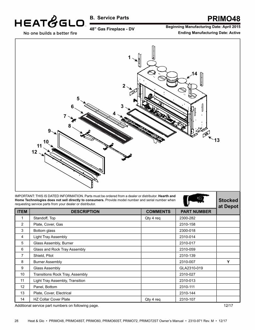
Heat & Glo • PRIMO48, PRIMO48ST, PRIMO60, PRIMO60ST, PRIMO72, PRIMO72ST Owner’s Manual • 2310-971 Rev. M • 12/17 28
Service Parts
IMPORTANT: THIS IS DATED INFORMATION. Parts must be ordered from a dealer or distributor. Hearth and Home Technologies does not sell directly to consumers. Provide model number and serial number when requesting service parts from your dealer or distributor.
Stocked at Depot
ITEM DESCRIPTION COMMENTS PART NUMBER1 Standoff, Top Qty 4 req 2300-2822 Plate, Cover, Gas 2310-1583 Bottom glass 2300-0184 Light Tray Assembly 2310-0145 Glass Assembly, Burner 2310-0176 Glass and Rock Tray Assembly 2310-0597 Shield, Pilot 2310-1398 Burner Assembly 2310-007 Y9 Glass Assembly GLA2310-01910 Transitions Rock Tray, Assembly 2310-02711 Light Tray Assembly, Transition 2310-01312 Panel, Bottom 2310-11113 Plate, Cover, Electrical 2310-14414 HZ Collar Cover Plate Qty 4 req 2310-107
Additional service part numbers on following page. 12/17
48” Gas Fireplace - DV
PRIMO48Beginning Manufacturing Date: April 2015
Ending Manufacturing Date: Active
1
2
34
56
7
89
1011
12
13
14
B. Service Parts
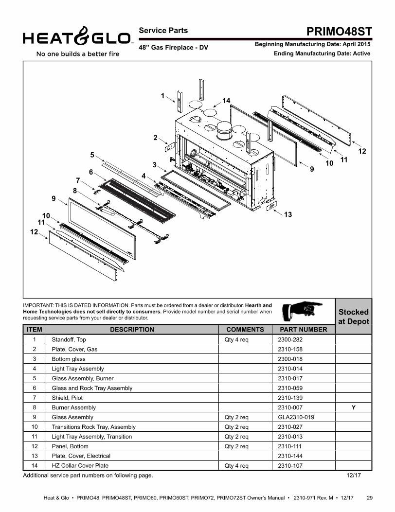
29Heat & Glo • PRIMO48, PRIMO48ST, PRIMO60, PRIMO60ST, PRIMO72, PRIMO72ST Owner’s Manual • 2310-971 Rev. M • 12/17
Service Parts
IMPORTANT: THIS IS DATED INFORMATION. Parts must be ordered from a dealer or distributor. Hearth and Home Technologies does not sell directly to consumers. Provide model number and serial number when requesting service parts from your dealer or distributor.
Stocked at Depot
ITEM DESCRIPTION COMMENTS PART NUMBER1 Standoff, Top Qty 4 req 2300-2822 Plate, Cover, Gas 2310-1583 Bottom glass 2300-0184 Light Tray Assembly 2310-0145 Glass Assembly, Burner 2310-0176 Glass and Rock Tray Assembly 2310-0597 Shield, Pilot 2310-1398 Burner Assembly 2310-007 Y9 Glass Assembly Qty 2 req GLA2310-01910 Transitions Rock Tray, Assembly Qty 2 req 2310-02711 Light Tray Assembly, Transition Qty 2 req 2310-01312 Panel, Bottom Qty 2 req 2310-11113 Plate, Cover, Electrical 2310-14414 HZ Collar Cover Plate Qty 4 req 2310-107
Additional service part numbers on following page. 12/17
48” Gas Fireplace - DV
PRIMO48STBeginning Manufacturing Date: April 2015
Ending Manufacturing Date: Active
1
2
34
5
67
89
1011
12
13
910 11
12
14
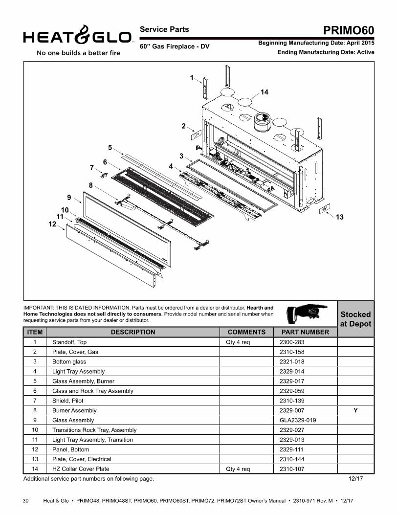
Heat & Glo • PRIMO48, PRIMO48ST, PRIMO60, PRIMO60ST, PRIMO72, PRIMO72ST Owner’s Manual • 2310-971 Rev. M • 12/17 30
Service Parts
IMPORTANT: THIS IS DATED INFORMATION. Parts must be ordered from a dealer or distributor. Hearth and Home Technologies does not sell directly to consumers. Provide model number and serial number when requesting service parts from your dealer or distributor.
Stocked at Depot
ITEM DESCRIPTION COMMENTS PART NUMBER1 Standoff, Top Qty 4 req 2300-2832 Plate, Cover, Gas 2310-1583 Bottom glass 2321-0184 Light Tray Assembly 2329-0145 Glass Assembly, Burner 2329-0176 Glass and Rock Tray Assembly 2329-0597 Shield, Pilot 2310-1398 Burner Assembly 2329-007 Y9 Glass Assembly GLA2329-01910 Transitions Rock Tray, Assembly 2329-02711 Light Tray Assembly, Transition 2329-01312 Panel, Bottom 2329-11113 Plate, Cover, Electrical 2310-14414 HZ Collar Cover Plate Qty 4 req 2310-107
Additional service part numbers on following page. 12/17
60” Gas Fireplace - DV
PRIMO60Beginning Manufacturing Date: April 2015
Ending Manufacturing Date: Active
1
2
34
5
67
8 9
1011
1213
14
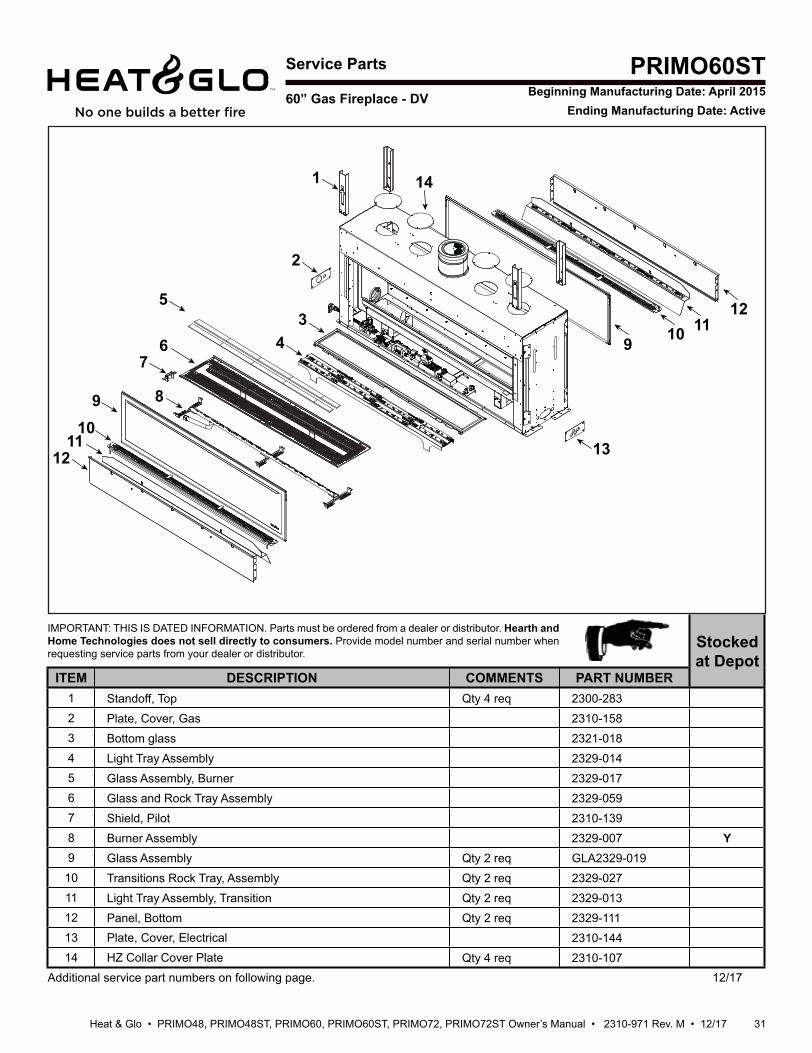
31Heat & Glo • PRIMO48, PRIMO48ST, PRIMO60, PRIMO60ST, PRIMO72, PRIMO72ST Owner’s Manual • 2310-971 Rev. M • 12/17
Service Parts
IMPORTANT: THIS IS DATED INFORMATION. Parts must be ordered from a dealer or distributor. Hearth and Home Technologies does not sell directly to consumers. Provide model number and serial number when requesting service parts from your dealer or distributor.
Stocked at Depot
ITEM DESCRIPTION COMMENTS PART NUMBER1 Standoff, Top Qty 4 req 2300-2832 Plate, Cover, Gas 2310-1583 Bottom glass 2321-0184 Light Tray Assembly 2329-0145 Glass Assembly, Burner 2329-0176 Glass and Rock Tray Assembly 2329-0597 Shield, Pilot 2310-1398 Burner Assembly 2329-007 Y9 Glass Assembly Qty 2 req GLA2329-01910 Transitions Rock Tray, Assembly Qty 2 req 2329-02711 Light Tray Assembly, Transition Qty 2 req 2329-01312 Panel, Bottom Qty 2 req 2329-11113 Plate, Cover, Electrical 2310-14414 HZ Collar Cover Plate Qty 4 req 2310-107
Additional service part numbers on following page. 12/17
60” Gas Fireplace - DV
PRIMO60STBeginning Manufacturing Date: April 2015
Ending Manufacturing Date: Active
1
2
34
5
67
8910
1112 13
14
9 10 1112
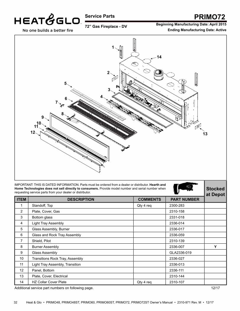
Heat & Glo • PRIMO48, PRIMO48ST, PRIMO60, PRIMO60ST, PRIMO72, PRIMO72ST Owner’s Manual • 2310-971 Rev. M • 12/17 32
Service Parts
IMPORTANT: THIS IS DATED INFORMATION. Parts must be ordered from a dealer or distributor. Hearth and Home Technologies does not sell directly to consumers. Provide model number and serial number when requesting service parts from your dealer or distributor.
Stocked at Depot
ITEM DESCRIPTION COMMENTS PART NUMBER1 Standoff, Top Qty 4 req 2300-2832 Plate, Cover, Gas 2310-1583 Bottom glass 2331-0184 Light Tray Assembly 2336-0145 Glass Assembly, Burner 2336-0176 Glass and Rock Tray Assembly 2336-0597 Shield, Pilot 2310-1398 Burner Assembly 2336-007 Y9 Glass Assembly GLA2336-01910 Transitions Rock Tray, Assembly 2336-02711 Light Tray Assembly, Transition 2336-01312 Panel, Bottom 2336-11113 Plate, Cover, Electrical 2310-14414 HZ Collar Cover Plate Qty 4 req 2310-107
Additional service part numbers on following page. 12/17
PRIMO72Beginning Manufacturing Date: April 2015
Ending Manufacturing Date: Active
1
34
5
76
8
2
910
1112 13
14
72” Gas Fireplace - DV
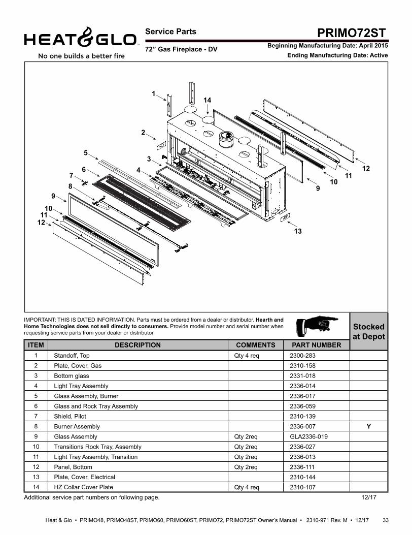
33Heat & Glo • PRIMO48, PRIMO48ST, PRIMO60, PRIMO60ST, PRIMO72, PRIMO72ST Owner’s Manual • 2310-971 Rev. M • 12/17
Service Parts
IMPORTANT: THIS IS DATED INFORMATION. Parts must be ordered from a dealer or distributor. Hearth and Home Technologies does not sell directly to consumers. Provide model number and serial number when requesting service parts from your dealer or distributor.
Stocked at Depot
ITEM DESCRIPTION COMMENTS PART NUMBER1 Standoff, Top Qty 4 req 2300-2832 Plate, Cover, Gas 2310-1583 Bottom glass 2331-0184 Light Tray Assembly 2336-0145 Glass Assembly, Burner 2336-0176 Glass and Rock Tray Assembly 2336-0597 Shield, Pilot 2310-1398 Burner Assembly 2336-007 Y9 Glass Assembly Qty 2req GLA2336-01910 Transitions Rock Tray, Assembly Qty 2req 2336-02711 Light Tray Assembly, Transition Qty 2req 2336-01312 Panel, Bottom Qty 2req 2336-11113 Plate, Cover, Electrical 2310-14414 HZ Collar Cover Plate Qty 4 req 2310-107
Additional service part numbers on following page. 12/17
PRIMO72STBeginning Manufacturing Date: April 2015
Ending Manufacturing Date: Active
141
2
34
5
678
9
1011
1213
910
1112
72” Gas Fireplace - DV
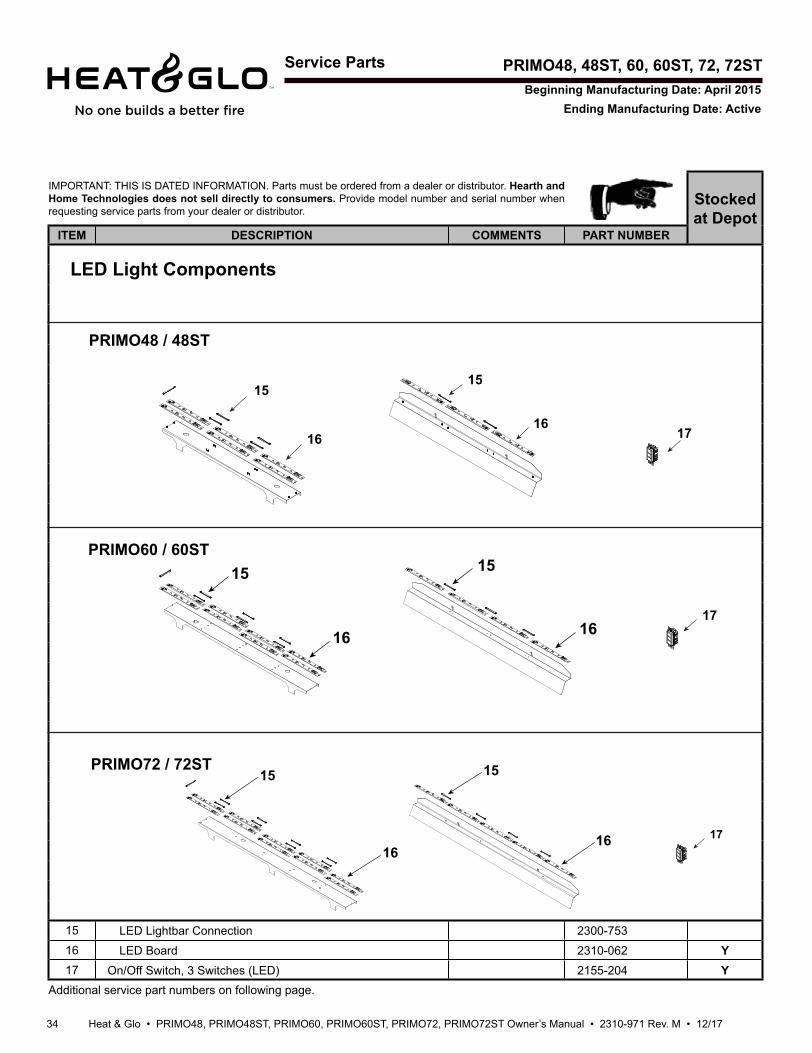
Heat & Glo • PRIMO48, PRIMO48ST, PRIMO60, PRIMO60ST, PRIMO72, PRIMO72ST Owner’s Manual • 2310-971 Rev. M • 12/17 34
Service Parts PRIMO48, 48ST, 60, 60ST, 72, 72ST
IMPORTANT: THIS IS DATED INFORMATION. Parts must be ordered from a dealer or distributor. Hearth and Home Technologies does not sell directly to consumers. Provide model number and serial number when requesting service parts from your dealer or distributor.
Stocked at Depot
ITEM DESCRIPTION COMMENTS PART NUMBER
15 LED Lightbar Connection 2300-75316 LED Board 2310-062 Y17 On/Off Switch, 3 Switches (LED) 2155-204 Y
Additional service part numbers on following page.
Beginning Manufacturing Date: April 2015Ending Manufacturing Date: Active
LED Light Components
15
16 17
15
16
17
15 15
1616
17
15
16
15
16
PRIMO48 / 48ST
PRIMO60 / 60ST
PRIMO72 / 72ST
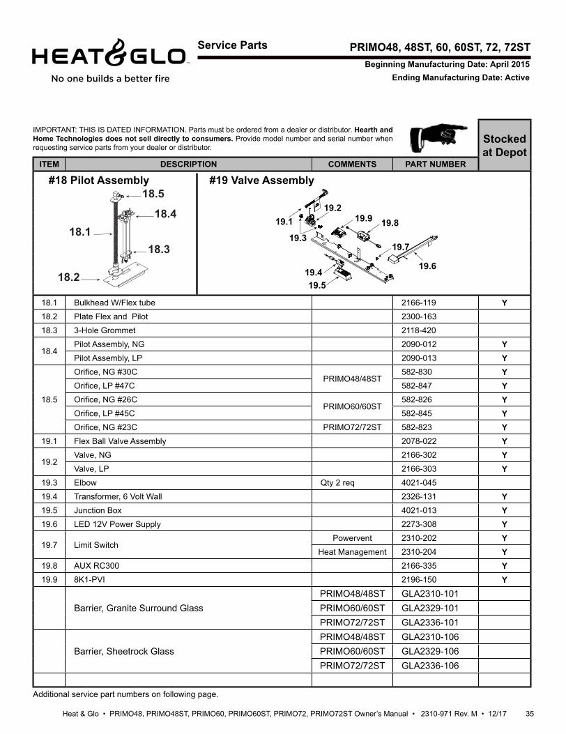
35Heat & Glo • PRIMO48, PRIMO48ST, PRIMO60, PRIMO60ST, PRIMO72, PRIMO72ST Owner’s Manual • 2310-971 Rev. M • 12/17
Service Parts
IMPORTANT: THIS IS DATED INFORMATION. Parts must be ordered from a dealer or distributor. Hearth and Home Technologies does not sell directly to consumers. Provide model number and serial number when requesting service parts from your dealer or distributor.
Stocked at Depot
ITEM DESCRIPTION COMMENTS PART NUMBER
18.1 Bulkhead W/Flex tube 2166-119 Y18.2 Plate Flex and Pilot 2300-163
18.3 3-Hole Grommet 2118-420
18.4Pilot Assembly, NG 2090-012 YPilot Assembly, LP 2090-013 Y
18.5
Ori ce, NG #30CPRIMO48/48ST
582-830 YOri ce, LP #47C 582-847 YOri ce, NG #26C
PRIMO60/60ST582-826 Y
Ori ce, LP #45C 582-845 YOri ce, NG #23C PRIMO72/72ST 582-823 Y
19.1 Flex Ball Valve Assembly 2078-022 Y
19.2Valve, NG 2166-302 YValve, LP 2166-303 Y
19.3 Elbow Qty 2 req 4021-045
19.4 Transformer, 6 Volt Wall 2326-131 Y19.5 Junction Box 4021-013 Y19.6 LED 12V Power Supply 2273-308 Y
19.7 Limit SwitchPowervent 2310-202 Y
Heat Management 2310-204 Y19.8 AUX RC300 2166-335 Y19.9 8K1-PVI 2196-150 Y
Barrier, Granite Surround GlassPRIMO48/48ST GLA2310-101PRIMO60/60ST GLA2329-101PRIMO72/72ST GLA2336-101
Barrier, Sheetrock GlassPRIMO48/48ST GLA2310-106PRIMO60/60ST GLA2329-106PRIMO72/72ST GLA2336-106
Additional service part numbers on following page.
PRIMO48, 48ST, 60, 60ST, 72, 72ST
18.1
18.2
18.3
18.4
18.5#18 Pilot Assembly #19 Valve Assembly
Beginning Manufacturing Date: April 2015Ending Manufacturing Date: Active
19.119.2
19.3
19.419.5
19.6
19.7
19.819.9
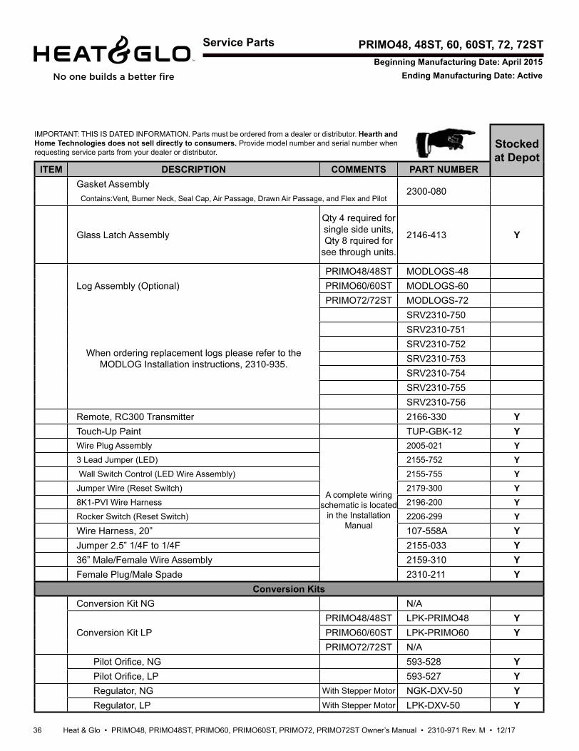
Heat & Glo • PRIMO48, PRIMO48ST, PRIMO60, PRIMO60ST, PRIMO72, PRIMO72ST Owner’s Manual • 2310-971 Rev. M • 12/17 36
Service Parts
IMPORTANT: THIS IS DATED INFORMATION. Parts must be ordered from a dealer or distributor. Hearth and Home Technologies does not sell directly to consumers. Provide model number and serial number when requesting service parts from your dealer or distributor.
Stocked at Depot
ITEM DESCRIPTION COMMENTS PART NUMBERGasket Assembly
2300-080 Contains:Vent, Burner Neck, Seal Cap, Air Passage, Drawn Air Passage, and Flex and Pilot
Glass Latch Assembly
Qty 4 required for single side units, Qty 8 rquired for
see through units.
2146-413 Y
Log Assembly (Optional)PRIMO48/48ST MODLOGS-48PRIMO60/60ST MODLOGS-60PRIMO72/72ST MODLOGS-72
When ordering replacement logs please refer to the MODLOG Installation instructions, 2310-935.
SRV2310-750SRV2310-751SRV2310-752SRV2310-753SRV2310-754SRV2310-755SRV2310-756
Remote, RC300 Transmitter 2166-330 YTouch-Up Paint TUP-GBK-12 YWire Plug Assembly
A complete wiring schematic is located
in the Installation Manual
2005-021 Y3 Lead Jumper (LED) 2155-752 Y Wall Switch Control (LED Wire Assembly) 2155-755 YJumper Wire (Reset Switch) 2179-300 Y8K1-PVI Wire Harness 2196-200 YRocker Switch (Reset Switch) 2206-299 YWire Harness, 20” 107-558A YJumper 2.5” 1/4F to 1/4F 2155-033 Y36” Male/Female Wire Assembly 2159-310 YFemale Plug/Male Spade 2310-211 Y
Conversion KitsConversion Kit NG N/A
Conversion Kit LPPRIMO48/48ST LPK-PRIMO48 YPRIMO60/60ST LPK-PRIMO60 YPRIMO72/72ST N/A
Pilot Ori ce, NG 593-528 YPilot Ori ce, LP 593-527 YRegulator, NG With Stepper Motor NGK-DXV-50 YRegulator, LP With Stepper Motor LPK-DXV-50 Y
PRIMO48, 48ST, 60, 60ST, 72, 72STBeginning Manufacturing Date: April 2015
Ending Manufacturing Date: Active

37Heat & Glo • PRIMO48, PRIMO48ST, PRIMO60, PRIMO60ST, PRIMO72, PRIMO72ST Owner’s Manual • 2310-971 Rev. M • 12/17
Heat & Glo, a brand of Hearth & Home Technologies7571 215th Street West, Lakeville, MN 55044
www.heatnglo.com
C. Contact Information
Please contact your Heat & Glo dealer with any questions or concerns. For the location of your nearest Heat & Glo dealer,
please visit www.heatnglo.com.
- NOTES -
________________________________________________________________________________
________________________________________________________________________________
________________________________________________________________________________
________________________________________________________________________________
________________________________________________________________________________
________________________________________________________________________________
________________________________________________________________________________
________________________________________________________________________________
________________________________________________________________________________
DO NOT DISCARD THIS MANUAL
NOTICE
• Leave this manual with party responsible for use and operation.
• Important operating and maintenance instructions included.
• Read, understand and follow these instructions for safe installation and operation.
Printed in U.S.A. - Copyright 2017
This product may be covered by one or more of the following patents: (United States) 5613487, 5647340, 5890485, 5941237, 6006743, 6019099, 6053165, 6145502, 6374822, 6484712, 6601579, 6769426, 6863064, 7077122, 7098269, 7258116, 7470729, 8147240 or other U.S. and foreign patents pending.
2000-945C