Cardiovascular implantable electronic devices: a review · PDF filecardiovascular implantable...
14
REVIEW Cardiovascular implantable electronic devices: a review of the dangers and difficulties in MR scanning and attempts to improve safety Pei Ghim Poh 1,2 & Charlene Liew 1 & Colin Yeo 3 & Le Roy Chong 1 & Andrew Tan 1 & Angeline Poh 1 Received: 22 December 2016 /Revised: 4 April 2017 /Accepted: 28 April 2017 /Published online: 17 June 2017 # The Author(s) 2017. This article is an open access publication Abstract An increasing number of patients are being treated with cardiovascular implantable electronic devices (CIEDs), many of which are MR conditional. There is a lack of literature on the safe scanning of MR conditional CIEDs. This review article discusses MR imaging safety in patients with implanted CIEDs. Guidelines on safe use and indications of imaging patients with MR conditional CIEDs are described, followed by a pictorial essay of the radiographic features of these devices. We also discuss the challenges of monitoring the patient in the MR environ- ment, advances in MRI conditional imaging of devices, availability, limitations and workflow including vendor- specific and other collaborative efforts to simplify the scanning process. Radiologists must be able to facilitate the safe utilization of MR imaging in patients who have CIEDs. A thorough knowledge of the hazards of imaging non-MR compatible devices is required as well as know- ing how to correctly identify and manage the imaging of patients with MR conditional CIEDs. Finally, we propose steps required to facilitate the safe scanning of patients with MR conditional CIEDs adopted in our institution and a contingency plan in the event that an inadvertent MR scan of a patient with a MRI unsafe CIED should occur. Main Messages • Risks of MR imaging in patients who have CIEDs have been worked around. • There are many technical limitations in enabling safe MR scanning of CIEDs. • Radiological identification of MRI-conditional status of CIEDs is useful. • Standardizing conditions for safe MRI scanning is important. • We offer example algorithms for facilitating safe MRI scan- ning of CIEDs. Keywords Equipment safety . Equipment design . Magnetic resonance imaging . Pacemaker . Artificial . Physics Introduction Magnetic resonance imaging (MRI) has steadily increased in use worldwide [1]. We believe that there is a foreseeable in- crease in the number of patients with cardiovascular implant- able electronic devices (CIEDs) who will require a MRI. An * Pei Ghim Poh [email protected] Charlene Liew [email protected] Colin Yeo [email protected] Le Roy Chong [email protected] Andrew Tan [email protected] Angeline Poh [email protected] 1 Department of Radiology, Changi General Hospital, 2 Simei Street 3, Singapore 529889, Singapore 2 Singhealth Radiology Residency, 167 Jalan Bukit Merah #17-10 Tower 5, Singapore 150167, Singapore 3 Department of Cardiology, Changi General Hospital, 2 Simei Street 3, Singapore 529889, Singapore Insights Imaging (2017) 8:405–418 DOI 10.1007/s13244-017-0556-3
Transcript of Cardiovascular implantable electronic devices: a review · PDF filecardiovascular implantable...

REVIEW
Cardiovascular implantable electronic devices: a reviewof the dangers and difficulties in MR scanning and attemptsto improve safety
Pei Ghim Poh1,2& Charlene Liew1
& Colin Yeo3 & Le Roy Chong1 & Andrew Tan1&
Angeline Poh1
Received: 22 December 2016 /Revised: 4 April 2017 /Accepted: 28 April 2017 /Published online: 17 June 2017# The Author(s) 2017. This article is an open access publication
AbstractAn increasing number of patients are being treated withcardiovascular implantable electronic devices (CIEDs),many of which are MR conditional. There is a lack ofliterature on the safe scanning of MR conditionalCIEDs. This review article discusses MR imaging safetyin patients with implanted CIEDs. Guidelines on safe useand indications of imaging patients with MR conditionalCIEDs are described, followed by a pictorial essay of theradiographic features of these devices. We also discuss thechallenges of monitoring the patient in the MR environ-ment, advances in MRI conditional imaging of devices,availability, limitations and workflow including vendor-
specific and other collaborative efforts to simplify thescanning process. Radiologists must be able to facilitatethe safe utilization of MR imaging in patients who haveCIEDs. A thorough knowledge of the hazards of imagingnon-MR compatible devices is required as well as know-ing how to correctly identify and manage the imaging ofpatients with MR conditional CIEDs. Finally, we proposesteps required to facilitate the safe scanning of patientswith MR conditional CIEDs adopted in our institutionand a contingency plan in the event that an inadvertentMR scan of a patient with a MRI unsafe CIED shouldoccur.
Main Messages• Risks of MR imaging in patients who have CIEDs have beenworked around.
• There are many technical limitations in enabling safe MRscanning of CIEDs.
• Radiological identification of MRI-conditional status ofCIEDs is useful.
• Standardizing conditions for safe MRI scanning isimportant.
• We offer example algorithms for facilitating safe MRI scan-ning of CIEDs.
Keywords Equipment safety . Equipment design .Magneticresonance imaging . Pacemaker . Artificial . Physics
Introduction
Magnetic resonance imaging (MRI) has steadily increased inuse worldwide [1]. We believe that there is a foreseeable in-crease in the number of patients with cardiovascular implant-able electronic devices (CIEDs) who will require a MRI. An
* Pei Ghim [email protected]
Charlene [email protected]
Colin [email protected]
Le Roy [email protected]
Andrew [email protected]
Angeline [email protected]
1 Department of Radiology, Changi General Hospital, 2 Simei Street 3,Singapore 529889, Singapore
2 Singhealth Radiology Residency, 167 Jalan Bukit Merah #17-10Tower 5, Singapore 150167, Singapore
3 Department of Cardiology, Changi General Hospital, 2 Simei Street3, Singapore 529889, Singapore
Insights Imaging (2017) 8:405–418DOI 10.1007/s13244-017-0556-3

estimated 75% of patients with CIEDs will have an indicationrequiring MRI during their lifetime [ 2].
This review article discusses the safe use ofMRI in patientswho have implanted CIEDs. Radiologists should have a basicgrasp of the principles behind the re-design and engineering ofthese devices, once considered to be an absolute contraindica-tion to scanning.
The known hazards of MRI unsafe CIEDs are described,followed by guidelines on safe use, indications and limitationsof imaging patients with MR conditional CIEDs, including abrief pictorial essay of the radiographic features of thesedevices.
Finally, we also offer steps to facilitate the safe scan-ning of patients with MR conditional CIEDs in the formof a proposed guideline, which was adopted in our insti-tution, and a contingency plan if an inadvertent MR scanof a patient with a MRI unsafe CIED should occur. Thesehave been ratified by the authors’ institutional medicalboard review process and have been implemented suc-cessfully at the time of writing.
What are MRI safe devices?
Implants, devices or materials should routinely undergo eval-uation prior to a MRI procedure if known, and are categorizedas safe, conditional or unsafe [3].
Safe devices are safe within the MR environment. Theobject is usually made from non-ferromagnetic components.There are no MR safe cardiovascular implantable devices atthe time of writing.
Conditional devices are safe for the patient undergoingMRI only if specific conditions are met. This is usually oftendue to the presence of a weakly ferromagnetic component inthe implantable device. Current recommendations supportsafe scanning at 1.5 T although several studies with scanningat 3 T exists.
Unsafe devices pose potential risk(s) to an individual in theMR environment, for which the physical concepts arediscussed below.
Hazards of imaging MRI unsafe cardiovasculardevices
A cardiac pacemaker system is composed of leads and a pulsegenerator. Within the pulse generator are connectors, circuitryand a battery which may be ferromagnetic. This results ininteractions with the magnetic field or RF pulse in MR envi-ronments [1, 2].
Magnetic field interactions include torque effect, inducedelectrical currents and reed/Hall sensor switch activation. RFpulse effects may also cause induced electrical currents andthe antenna effect. All reported MRI-induced burns originate
from electromagnetic induction or the antenna effect. Previousstudies [4, 5] identifying issues regarding such interactionshave formed the basis for the engineering of MR conditionaldevices (See Fig. 1).
Torque effect
The presence of ferromagnetic materials in the device maylead to movement or vibration in a MR environment. Theforces are directly related to the shape and amount of theferromagnetic material as well as the field strength and itslocation within the magnetic field [6]. The torque inducedby the magnetic field may result in movement of internalcomponents or dislodgement of i ts components.Prospective studies on conventional and MRI-conditionalpacemakers have not demonstrated significant adverse ef-fects [7, 8].
Induced electrical currents
Electromagnetic energy may conduct through the pacing sys-tem due to a change in magnetic flux, sources of which in-clude the pulsed radiofrequency energy from a surface coil [9]and the time-varying magnetic fields used for the spatial lo-calization of signals [10].
The transfer of magnetic radiofrequency energy to heat andelectrical energy depends on the pulse sequence parameters,the whole-body averaged and specific absorption rates (SAR),spatial relation and orientation with regards to the coil andconfiguration of the lead (composition, length and orientation)[6].
Induced electrical currents may mimic intrinsic cardiacactivity. This may result in oversensing (where activity isinterpreted as ventricular tachycardia) or undersensing(failure to sense native cardiac activity) resulting in aninappropriate high rate or an inhibition of pacing inCIEDs. In implantable cardioverter defibrillators (ICDs),this may result in inappropriate shock therapy [3].Heating may also cause direct tissue damage such asoedema and formation of scar tissue at the lead-tissueinterface [1, 11].
Antenna effect
Another mechanism, which can result in heating, occurs whena wire of appropriate length is exposed to RF frequency andacts as an antenna. The amplitude of this effect is maximizedat the resonant length of the antenna, generating electromag-netic oscillation, mainly at the antinodes or lead tips [12, 13].This results in heat generation at the ends of the wire.
Subsequently, resultant sensing or capture threshold chang-es occur and may result in rapid pacing or loss of signal
406 Insights Imaging (2017) 8:405–418

capture [10, 14], potentially causing inappropriate inhibitionof demand pacing or tachycardia therapies.
Reed switch activation
Older devices have a magnetically-activated reed switch,consisting of two metal strips in a glass capsule and can beactivated or inactivated by an external magnetic field.Activation or deactivation depends on the orientation of theswitch in relation to the static magnetic field (See Fig. 2).
When kept in open/closed positions, the CIED may alsopermanently disable tachycardia therapies or result in asyn-chronous pacing and this may be life-threatening in patientswith recent myocardial infarction, hypoxemia or major elec-trolyte imbalance. Activation of the reed switch results in apreset pacing rate and may theoretically induce VF or aggra-vate myocardial ischemia. There may also be accelerated bat-tery depletion [3, 15].
Engineering CIEDs to make them MR conditional
Almost all hazards related to CIEDs in MR environmentsare due to the presence of ferromagnetic content. Thereare two main ways to reduce magnetic field interaction.Firstly, through the minimization of ferromagnetic contentof the generator and leads. This limits the choice of ma-terial which should be conductive, durable and biocom-patible. The second method is to prevent the ferromagnet-ic content from interacting with the magnetic field, whichcan be achieved by using a lower magnetic field strengthor by modification of the lead design. MRI-compatibleleads can be identified by their vendor-specific identifierwhich will be covered in a separate section (See Fig. 3).
Lead modification
Any wire in contact with soft tissue can result in tissuedamage from heating and thus, insulation is required.However, as insulation thickness increases, local SAR al-so increases, resulting in increased heating at the tip.However, with specially designed leads, heating can belimited to below 1–2 degrees Celsius. An example of leaddesign changes in a MR conditional lead is a change inthe pitch of the inner coil. Other methods include havingfewer coiled filars, increasing the number of windingturns and, therefore, increasing lead inductance. Thislimits the radiofrequencies that can resonate through thelead filaments [16].
The use of bipolar sensing and low-pass filters reducesconducted and radiated interference. Additionally, feed-through capacitor filters are utilized to prevent electromagnet-ic induction from a wide range of frequencies [10].
Lead-tissue interface
Whilst most of the lead is insulated, a lead-tissue interfaceallows bare wire to be in contact with soft tissue. In someanimal models, noise or loss of capture in tips was noted afterbeing exposed to MRI [17]. It was found that there was anincrease in the lead tip temperature as well as oedema at thelead-tissue interface. Steroid-elution technology is one of themethods used to try to reduce inflammation at site of contactand to prevent threshold changes to produce consistent opti-mal threshold behaviour [18].
The use of titanium nitride, a biocompatible alloy, tocoat electrodes has also been shown to avoid interfer-ence caused by noise by shifting the frequency of theband pass towards the lower frequency spectrum, there-by improving sensing performance [19]. Increased sur-face area of the lead tip in contact with soft tissue canresult in reduced torque effects and a better coolingmechanism. For example, St Jude Medical employs theuse of soft silicone pads at the tips, allowing a largertip to be introduced through a smaller introducer due tothe soft nature of the material, effectively reducing thetip pressure by approximately 50% in their test reports[20]. Allowing 6 weeks to elapse post-implantation al-lows better wound healing and fixation, thus reducingthe effects of torque [9].
Pulse generator shielding
Hermetically-sealed titanium or stainless steel cases are typi-cally used to shield CIED generators and recently,nanomagnetic insulation has been used in leads to improveshielding from radiofrequency and time-varying gradientmagnetic fields [10].
Safety mechanisms
A magnet-activated switch such as a reed switch was de-signed to prevent adverse effects due to magnetic fieldinteractions. This was considered unreliable and has nowbeen replaced with Hall sensors. Hall sensors are based onthe generation of voltage across an electrical conductor(See Fig. 4).
When the magnetic field is perpendicular to the direction ofthe conductor current flow, varied output voltage is generatedin response to a magnetic field. Thus, this has a more predict-able behaviour compared to a reed switch and can be ‘lockedout’ when undergoing MRI. These switches function as trans-ducers to trigger an electronic switch to ‘ON’ or ‘OFF’ whenactivated by a magnetic field. This halts inappropriate treat-ment during scanning [4, 5].
Insights Imaging (2017) 8:405–418 407

Challenges of monitoring patients in the MRenvironment
A cardiologist should clear the patient for scanning and pa-tients are supervised by a healthcare professional with appro-priate training throughout the procedure, usually a cardiologistor pacemaker nurse. During scanning, sensing is stopped anddiagnostics testing will be unavailable.
Pulse oximetry and ECG are standard devices that are in-tegrated into the MRI room. These contain circuitry with spe-cially designed ECG electrodes containing a minimal amountof metal. Standard ECG electrodes and leads may potentiallyburn the patient due to excessive heating. Artefacts may alsoaffect ECG readings which are crucial for gated MRI proce-dures. Several techniques have been shown to reduce ECGartefacts, for example: positioning the line parallel to the mag-netic field flux lines and placing limb electrodes close to eachother [21, 22].
Back-up therapy should be available, some of which mayhave to be placed outside the MRI room. Other devices that
can be modified include gurneys, oxygen tanks, stethoscopes,suction devices, infusion pumps and power injectors.Ventilators must also be modified due to the presence of me-chanical switches or ferromagnetic components. Some venti-lators only operate at a ‘safe’ distance from the MRI machinedue to their ferromagnetic components [23]. These devices areMRI-conditional. Where temperature must be monitored,fluoroptic thermometry can be used [24].
Although no strict monitoring standard exists, a set of rec-ommendations has been published in a joint statement by theCanadian Heart Rhythm Society and Canadian Association ofRadiologists [25].
MRI modes
MRI mode refers to changing CIED settings to accommodatean MRI environment such that oversensing and inappropriatetherapy can be minimized and restoration of prescan programstates and values are simplified [26]. MRI modes for MRI-conditional devices vary between different devices and man-ufacturer instructions should be followed. No standard ap-proach exists between the different devices, but the conceptsare akin to those in non-MRI-conditional devices.
It remains contradictory that in day-to-day radiology prac-tice there have been clinical studies which show relative safetyof scanning patients with CIEDs that are not MRI-conditionalwhilst most regulatory bodies continue to advocate scanningonly MRI-conditional devices. This is may be revised in thefuture with an updated regulatory framework. In non-conditional devices, several parameters can be changed tomake scanning safer. Patients with pacemakers are generallysplit between pacemaker-dependent patients and non-pacemaker dependent patients. ICD devices also require de-activation. These are clearly documented in the ESC guide-lines and discussed below [27].
Fig. 1 MR hazards which pose arisk to patients with MRI unsafecompatible CIEDs
Fig. 2 Diagram shows reed switch activation by a magnetic field
408 Insights Imaging (2017) 8:405–418
Sensing only mode
This is often used in non-pacemaker-dependent patients. Thepacemaker is programmed to off/sub-threshold outputs andthe lead polarity is changed to bipolar [28].
Asynchronous mode (DOO/VOO/AOO)
This is often used in pacemaker-dependent patients who are ina higher-risk group. In asynchronous mode, pacing occurs at a
fixed rate which is well tolerated for short periods of time.There is an extremely low risk of developing VF during asyn-chronous pacing, and; hence, prolonged asynchronous pacingshould be avoided [28].
ICD temporary deactivation
ICD devices may falsely detect VT and subsequently deliverpacing, cardioversion or defibrillation therapies which maylead to actual arrhythmias. Although an in-built safety
Fig. 3 Schematic diagram details the various components of CIEDs, which have been re-engineered to make these MR-conditional
Fig. 4 A Hall sensor varies itsoutput voltage in response to amagnetic field
Insights Imaging (2017) 8:405–418 409

mechanism exists within the device, such as reed and Hall-sensor switches, deactivation remains a safer and predictableoption.
Although scanning patients with non-conditional MRI de-vices carry additional risks, the actual rate of adverse eventsremains very low. A multicentre study (MagnaSafe Registry)has shown that in 1000 cases in which patients had a non-conditional MRI pacemaker and 500 cases in which patientshad a non-conditional MRI ICD, only one ICD required im-mediate replacement, and the said device was not pro-grammed appropriately before the MRI. Device parameterchanges were common but only exceeded pre-specifiedthresholds in a small number of cases. Six cases of self-terminating atrial fibrillation/flutter and six cases of partial
electrical reset were observed. There were no cases in whichfull electrical reset of the device
occurred [29].At the time of this writing, the ESC strongly recommends
against scanning patients with non-MRI-conditional pace-makers, especially those who are pacemaker-dependent. It isprudent to consider MRI as a last resort although perspectivesmay change with the release of additional data [30].
It is also important to note that pacemaker dependentpatients who have an ICD are excluded from theMagnasafe Registry. No validated guideline exists for thissubset of patients but asynchronous VOO mode with de-activation of ICD parameters appears to be a reasonableapproach [31].
Fig. 6 Radiographic images(magnified) demonstrate identifi-er labels on a a MR conditionalpacemaker (Accent™ MRI, usedwith permission) b MR condi-tional lead (Tendril™, used withpermission) c MRI unsafe pace-maker (Accent™, used withpermission)
Fig. 5 Flowchart demonstratinga streamlined workflow with theincorporation of a hand-held ex-ternal activator (St Jude Medical,used with permission)
410 Insights Imaging (2017) 8:405–418

MRI of non-conditional CIEDs should not be considered asroutine. Special precautions and patient selection is neededincluding requiring a cardiologist who has working knowl-edge to interrogate pacemakers and ICDs and where available,assistance of an industry device representative. The risk oflead removal for scanning is still probably higher than scan-ning non-MRI-conditional CIEDs under close surveillance[32].
Difficulties faced in MR scanning of CIEDand attempts to improve the scanning process
The need to follow the vendor-specific protocol for eachMR conditional device
Each company has their own specific algorithm to program aCIED to ‘MRI-mode’. Common features include disablingbradycardia and tachycardia therapy. Once the patient hasbeen removed from the scanner, the device will be pro-grammed back to pre-scan settings.
Each manufacturer usually provides their own genericcheck list and algorithm specifics. It is impossible for radio-logical staff to remember the specific manufacturer-definedsafety conditions for every single device.
Recently, there have been attempts to simplify and reducethe number of steps within the algorithm and reduce theamount of time the patient remains in MRI mode. The careprogram pathway by St Jude is a proposed workflow for prep-aration of patients with pacemakers undergoing MRI. Thegoal is to minimize the time the patient is required to be inMRI mode. The time the patient needs to be in ‘MRI mode’can be further reduced by external hand-held activators whichsimplify access to MRI settings [31, 33] (See Fig. 5).
Key considerations for an effective framework for the safescanning of CIED patients are:
1) Registry to find out the specific model for the implant2) Details regarding certain conditions in which the device is
MRI-conditional3) Parameters for scanning which will need to be adjusted
for the specific device4) Re-programming to pre-scan conditions after scanning
Philips has proposed its own method to simplify this pro-cess using a mechanism known as BScanwise^. Scanwise al-lows automatic scan parameter adjustments to match eachspecific MR conditional implant. The technology is also ableto reduce near metal susceptibility artefacts but this is mainlytargeted at orthopaedic implants, and the efficacy in reducingartefacts from CIEDs is unknown [34].
The Sorin group has also its automatic MRI mode exclu-sively available in its KORA 100 and KORA 250 models,where the device can switch automatically to asynchronousmode when a strong magnetic field is detected. The device
Fig. 7 Magnified radiographicimages demonstrate Medtronicmanufacturer specific markers(images used with permission). a-b pacemakers which are MRconditional cMR conditional leadd MRI unsafe pacemakeridentifier
Fig. 8 Enhanced radiographic image of the radiopaque marker for theBiotronik EviaTM device (image used with permission). This device hasno specific marker to show that it is MR-conditional; hence, there is aneed to identify the device model and family
Insights Imaging (2017) 8:405–418 411

switches back 5 min after the patient is removed from themagnetic field [35].
Coordination and communication with cardiologistsand manufacturer cooperation
A cardiologist or pacemaker technician should be present forthe device to be switched into MR compatible-mode althoughthis may change in the future. Lack of familiarity or inabilityto identify the device model may affect decision-making onthe type of scan, and a scan may be rejected based on safetygrounds. Radiologists should take the initiative to advise re-ferring clinicians when a MRI scan is warranted but has notbeen considered due to presence of an implant.
Ideally, a central repository by manufacturers for the iden-tification and instructions for use and MRI conditional avail-ability of all their devices, should be created for cardiologists,radiologists and referring clinicians. Another solution is to
create a standard industry design platform to allow manufac-turers to standardize the process in which MRI-conditionaldevices are activated. However, availability of differentmodels may result in difficulty in implementing a standard-ized algorithm, and the issue of propriety systems will furtherprevent vendors from cooperating to create a one-size-fits-allsystem.
Availability and limitations of novel devices
The availability of MRI-compatible cardiac implantable elec-tronic devices varies by country, but this is driven primarily bycountry-specific regulatory approvals.
In most countries around the world, MRI compatible car-diac devices should be available for use, although specificmodel availability would differ. For example, the KORA100and KORA 250 are not available for sale or distribution in theUSA.
Fig. 9 Magnified radiographicimages demonstrate radiopaqueidentifiers from BostonScientificdevices aMR conditional devicesb MRI unsafe devices and c MR-conditional lead. (images usedwith permission)
Fig. 10 Sorin Group MRIcompatible pacemakers. Look fortheMSPYidentifier. (images usedwith permission)
412 Insights Imaging (2017) 8:405–418

Limitations of MR conditional devices
MR-conditional devices must be used within a set of definedparameters for these to function safely during a scan.
Patients must wait 6 weeks after implantation prior toMRI,and many of these devices are not recommended within a fieldstrength above certain field strengths. Pre-existing devices,old leads and pulse generators must be removed for replace-ment if a new pacemaker is to be inserted.
Certain CIED models cannot be scanned with the iso-center over the thorax, although newer models have no zonalrestriction. Some devices still require specialized personneland monitoring.
Lastly, there is increased cost compared to conventionaldevices. Therefore, MR-conditional CIEDs are often more
favourable for younger patients or in those who are morelikely to require MR studies in their lifetime [36].
Pictorial review of the radiographic featuresof MR-conditional devices
Plain radiographs may be used to identify the pacemaker as aMR-conditional device as there are manufacturer and model-specific markers. In cases where the device model cannot beread due to positioning, certain features of the markers andcomponents may be used to indicate if a CIED is MR-conditional [37]. Unfortunately, these markers are unique toeach manufacturer and conditions prior to scanning differfrom model to model.
In the rare occasion where the patient’s implantation re-cords are unavailable, it is often useful to be able to visually
Fig. 11 Table demonstrates magnified device radiopaque markers from various manufacturers
Fig. 12 Chest radiograph demonstrating an AICD in situ. A limitednumber of AICDs are MR-conditional, such as the Medtronic Evera™MRI ICD and BioTronik ProMRI® AICD
Fig. 13 The subcutaneous electrode is implanted in the left parasternalposition. There is currently only one manufacturer with this device(Cameroon Health/Boston Scientific)
Insights Imaging (2017) 8:405–418 413

identify if a device is MR-compatible. The following is apictorial review of the different types of CIEDs and methodsto identify the model and MR compatibility across severalmanufacturers.
St Jude [37] (See Fig. 6)
Medtronic [38] (See Fig. 7)
Biotronik (See Fig. 8)
Boston Scientific (See Fig. 9)
Sorin Group [36] (See Fig. 10)
Summary diagram (See Fig. 11)
MR conditional implantable cardioverter-defibrillator(ICD) [37, 39]
This is radiographically similar to pacemakers apart fromhigh-voltage defibrillation coils which appear as thick bandsat the SVC and RVapex (See Fig. 12).
Subcutaneous ICDs (SICD)
A SICD has no transvenous leads and does not make con-tact with the heart. The pulse generator is usually locatedalong the left lateral chest wall.
A study of 22 examinations (15 patients) showed noevidence of tissue injury, device malfunction or interac-tion with programmed parameters during MR scanning.Unlike transvenous ICDs, heating of the electrode doesnot harm the myocardium but may cause severe discom-fort. Even so, more data is required to support the SICDas a MRI conditional device (See Fig. 13) [40].
Implantable loop recorders (ILR)
This is a leadless device with the appearance of aBUSB stick^ or cricket-bat. The device is MR-conditional,although device memory/ECG recording will be inaccu-rate during scanning. Artefacts may mimic arrhythmia,and this should be taken into consideration. Prior to scan-ning, the patient should be warned about a tugging sensa-tion (See Fig. 14) [41].
Permanent leadless pacemakers (PLP)
PLPs are implanted within the heart, often within theright ventricle. These are not detectable on physical ex-amination and may not be sensed by a metal detector.Recently, MRI-compatible devices have been released in-to the market [42].
Abandoned leads
A single-lead right-sided pacemaker is present. There isalso an abandoned left-sided lead without the pulse generatorunit, indicated by an arrow (See Fig. 15).
An abandoned lead is disconnected from the pulse genera-tor, left behind due to fracture, insulation breaks, dislodgmentor other failure. Langman DA, et al. showed that abandonedleads exhibited increased lead tip heating compared to
Fig. 15 A single-lead right-sided pacemaker is present. There is also anabandoned left-sided lead without the pulse generator unit, indicated byan arrow.
Fig. 14 A single-lead right-sided pacemaker is present. There is also anabandoned left-sided lead without the pulse generator unit
414 Insights Imaging (2017) 8:405–418
pacemaker-attached leads [43]. Even if the lead is MR com-patible, MRI is not recommended.
Algorithm and protocols
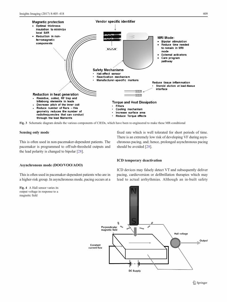
MRI-conditional algorithm
An algorithm has been developed in our institution toensure that patients with CIEDs can be MR scanned safe-ly. The first two steps of this algorithm include a mecha-nism in-built into the hospital computerized order entrysystem where the requesting clinicians also are requiredto complete a set of checklists as a part of the patient’scare pathway (See Fig. 16).
Proposed inadvertent scanning prevention algorithm
Another algorithm was developed in our institution to preventinadvertent scanning of patients with CIEDs. Three funda-mental actions are incorporated (See Fig. 17):
• checking clinical history• checking for prior chest radiograph• sweeping with a metal detector.
Fig. 16 Algorithm for the MR scanning of patients with CIEDs
Fig. 17 Algorithm for the prevention of inadvertent scanning of patientswith CIEDs (Both MR-conditional and non-MR conditional)
Insights Imaging (2017) 8:405–418 415
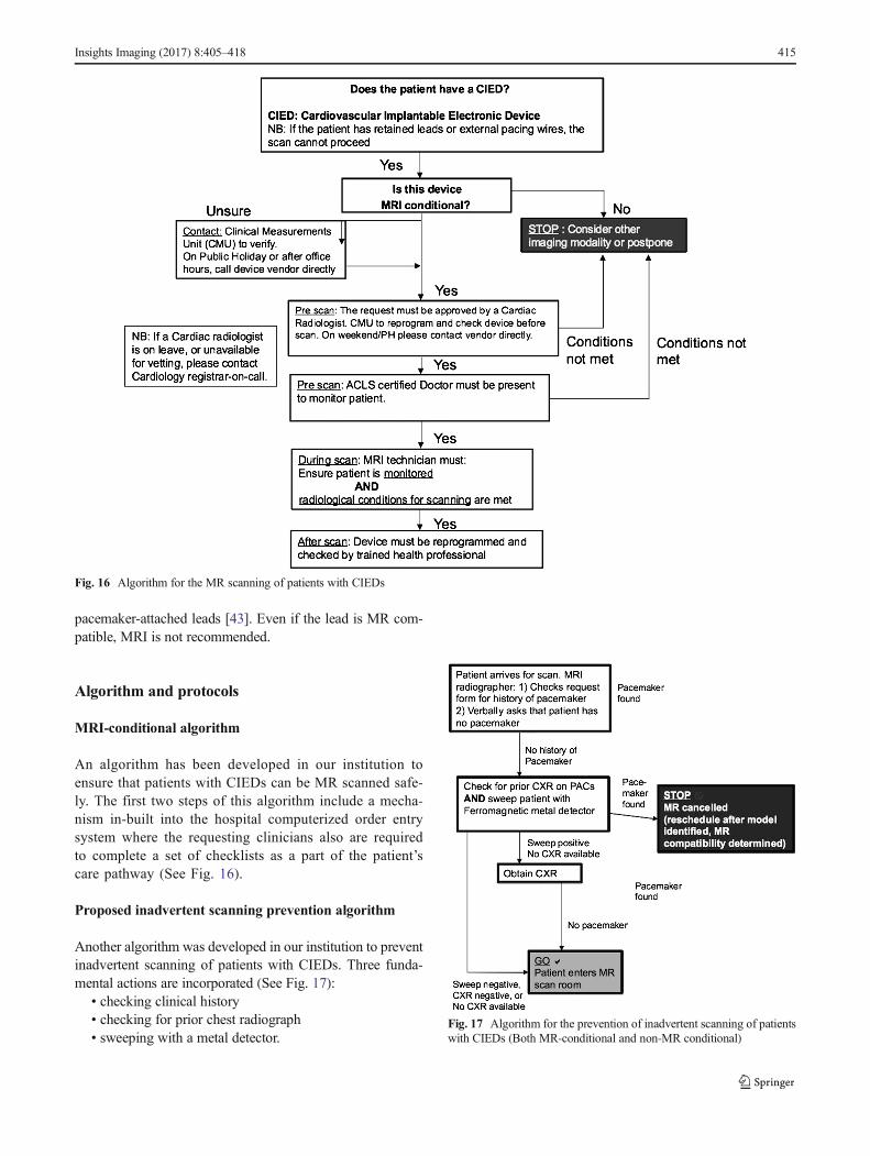
Proposed contingency plan after inadvertent scanning
We propose a contingency plan used in our institution shouldan inadvertent MR scan of a patient with a MRI unsafe CIEDoccur (See Fig. 18).
Conclusion
There is an increasing number of patients with CIEDSwho will require MRI. Radiologists must be able to facil-itate the safe utilization of MRI in patients who haveCIEDs.
Note: Previous related electronic exhibit presentedat: American Roentgen Ray Society Annual Meeting 2014,Toronto [44].
Open Access This article is distributed under the terms of the CreativeCommons At t r ibut ion 4 .0 In te rna t ional License (h t tp : / /creativecommons.org/licenses/by/4.0/), which permits unrestricted use,distribution, and reproduction in any medium, provided you give appro-priate credit to the original author(s) and the source, provide a link to theCreative Commons license, and indicate if changes were made.
References
1. Götte MJW, Rüssel IK, de Roest GJ et al (2010) Magnetic resonanceimaging, pacemakers and implantable cardioverter-defibrillators:current situation and clinical perspective. Neth Hear J 18(1):31–37
2. Chow GV, Nazarian S (2014 May) MRI for patients with cardiacimplantable electrical devices. Cardiol Clin 32(2):299–304
3. Shellock FG, Spinazzi A (2008) MRI safety update 2008: part 2,screening patients for MRI. AJR Am J Roentgenol 191(4):1140–1149
Fig. 18 Algorithm after inadvertent scan of patient with CIED
416 Insights Imaging (2017) 8:405–418

4. Shinbane J, Colletti P, Shellock FG (2007) MR in patients withpacemakers and ICDs: defining the issues. J Cardiovasc MagnReson 9(1):5–13
5. Nazarian S, Hansford R, Roguin A et al (2011) A prospective eval-uation of a protocol for magnetic resonance imaging of patientswith implanted cardiac devices. Ann Intern Med 155(7):415–424
6. Shinbane JS et al (2011) Magnetic resonance imaging in patientswith cardiac pacemakers: era of "MR conditional" designs. JCardiovasc Magn Reson 13:63
7. Del Ojo JL, Moya F, Villalba J, Sanz O, Pavon R, Garcia D, PastorL (2005) Is magnetic resonance imaging safe in cardiac pacemakerrecipients? Pacing Clin Electrophysiol 28(4):274–278
8. Naehle CP, Meyer C, Thomas D et al (2008) Safety of brain 3-TMR imaging with transmit-receive head coil in patients with cardiacpacemakers: pilot prospective study with 51 examinations.Radiology 249(3):991–1001
9. Kodali S, Baher A, Shah D (2013) Safety of MRIs in patients withpacemakers and defibrillators. Methodist Debakey Cardiovasc J9(3):137–141
10. Beinart R, Nazarian S (2013) Effects of external electricaland magnetic fields on pacemakers and defibrillators: fromengineering principles to clinical practice. Circulation128(25):2799–2809
11. Luechinger R, Zeijlemaker VA, Pedersen EM et al (2005) In vivoheating of pacemaker leads during magnetic resonance imaging.Eur Heart J 26(4):376–383
12. Dempsey MF, Condon B, Hadley DM (2001) Investigation of thefactors responsible for burns during MRI. J Magn Reson Imaging13(4):627–631
13. Mattei E, Triventi M, Calcagnini G et al (2008) Complexity of MRIinduced heating on metallic leads: experimental measurements of374 configurations. Biomed Eng Online 7:11
14. Fontaine JM, Mohamed FB, Gottlieb C, Callans DJ, MarchlinskiFE (1998) Rapid ventricular pacing in a pacemaker patient under-going magnetic resonance imaging. Pacing Clin Electrophysiol 21:1336–1339
15. Jacob S, Panaich SS, Maheshwari R, Haddad JW, Padanilam BJ,John SK (2011) Clinical applications of magnets on cardiac rhythmmanagement devices. Europace 13(9):1222–1230
16. Bottomley PA et al (2010) Designing passiveMRI-safe implantableconducting leads with electrodes. Med Phys 37(7):3828–3843Medtronic For Healthcare Professionals: Pacing Leads
17. Roguin A, Zviman MM, Meininger GR, Rodrigues ER, DickfieldTM, Bluemke DA et al (2004) Modern pacemaker and implantablecardioverter/defibrillator systems can be magnetic resonance imag-ing safe. In vitro and invivo assessment of safety and function at1.5T. Circulation 110:475–482
18. Crossley GH, Brinker JA, Reynolds D et al (1995) Steroid elutionimproves the stimulation threshold in an active-fixation atrial per-manent pacing lead. A randomized, controlled study. Model 4068investigators. Circulation 92(10):2935–2939
19. Schaldach M, Hubmann M, Hardt R, Weikl A (1989) Titaniumnitride cardiac pacemaker electrodes. Biomed Tech (Berl) 34(7–8):185–190
20. St Jude Medical. Tendril MRI™ Pacing Lead - St. Jude Medical.Information for healthcare professionals. Last updated 16 August16. Accessed 05/12/2016. Website: http://professional-intl.sjm.com/products/crm/leads/pacing-leads/tendril-mri
21. Kanal E, Barkovich AJ, Bell C et al (2007) ACR guidance docu-ment for safe MR practices: 2007. AJR Am J Roentgenol 188:1447–1474
22. Kanal E, Shellock FG (1992) Patient monitoring during clinicalMRimaging. Radiology 185:623
23. Greenberg KL, Weinreb J, Shellock FG (2011) "MR conditional"respiratory ventilator system incident in a 3-T MRI environment.Magn Reson Imaging 29:1150–1154
24. Nasr VG et al (2012) Performance validation of a modified mag-netic resonance imaging-compatible temperature probe in children.Anesth Analg 114:1230–1234
25. Verma A, Ha AC, Dennie C et al (2014) Canadian Heart RhythmSociety and Canadian Association of Radiologists consensus state-ment onmagnetic resonance imaging with cardiac implantable elec-tronic devices. Can J Cardiol 30(10):1131–1141
26. Jung W, Zvereva V, Hajredini B, Jäckle S (2012) Safe magneticresonance image scanning of the pacemaker patient: current tech-nologies and future directions. Europace 14(5):631–637
27. Brignole M, Auricchio A, Baron-Esquivias G et al (2013) 2013ESC guidelines on cardiac pacing and cardiac resynchronizationtherapy: the task force on cardiac pacing and resynchronizationtherapy of the European Society of Cardiology (ESC). Europace15:1070–1118
28. Russo RJ (2013) Determining the risks of clinically indicatednonthoracic magnetic resonance imaging at 1.5 T for patients withpacemakers and implantable cardioverter-defibrillators: rationaleand design of the MagnaSafe Registry. Am Heart J 165:266–272
29. Russo RJ, Costa HS, Silva PD et al (2017) Assessing the risksassociated with MRI in patients with a pacemaker or defibrillator.N Engl J Med 376(8):755–764
30. Moss AJ, Kutyifa V (2015) Safe MRI in patients with an upgraded(conditional) implantable cardioverter-defibrillator: the beneficial tipof a troublesome iceberg∗. J Am Coll Cardiol 65(24):2589–2590
31. Ferreira AM, Costa F, Tralhão A,Marques H, CardimN, Adragão P(2014) MRI-conditional pacemakers: current perspectives. MedDevices (Auckl) 7:115–124
32. Gimbel JR, Bailey SM, Tchou PJ, Ruggieri PM,Wilkoff BL (2005)Strategies for the safe magnetic resonance imaging of pacemaker-dependent patients. Pacing Clin Electrophysiol 28:1041–1046
33. St Jude Medical. Guidelines for St. Jude Medical™ MRConditional Pacing Systems. St. Jude Medical. Information forhealthcare professionals. Last updated June 2014. Accessed 05/12/2016. Website: https://www.sjm.com/professional/resources/emi/~/media/B9E77F345D6344F8BCADC359036F8E43.ashx
34. J Brink et al. Philips Scanwise Implant Whitepaper, Simplify scan-ning of patients with MR Conditional implants. Koninklijke PhilipsN.V. Apr 2016. Accessed 06/12/2016. Website: http://www.usa.philips.com/b-dam/b2bhc/master/events/ISMRM2016/philips-scanwise-implant-whitepaper.pdf
35. Savouré A, Mechulan A, Burban M, Olivier A, Lazarus A (2015)The Kora pacemaker is safe and effective for magnetic resonanceimaging. Clin Med Insights Cardiol 9:85–90
36. Cronin EM, Wilkoff BL (2012) Magnetic resonance imaging con-ditional pacemakers: rationale, development and future directions.Indian Pacing Electrophysiol J 12(5):204–212
37. Alandete Germán SP, Isarria Vidal S, Domingo Montañana ML,Dela Vía Oraá E, Vilar Samper J (2015) Pacemakers and implant-able cardioverter defibrillators, unknown to chest radiography: re-view, complications and systematic reading. Eur J Radiol 84(3):499–508
38. Costelloe CM, Murphy WA, Gladish GW, Rozner MA(2012) Radiography of pacemakers and implantablecardioverter defibrillators. AJR Am J Roentgenol 199(6):1252–1258
39. Aguilera AL, Volokhina YV, Fisher KL (2011) Radiography ofcardiac conduction devices: a comprehensive review.Radiographics 31(6):1669–1682
40. Keller J, Neužil P, Vymazal J et al (2015) Magnetic resonanceimaging in patients with a subcutaneous implantable cardioverter-defibrillator. Europace 17(5):761–766
41. Gimbel JR, Zarghami J, Machado C, Wilkoff BL (2005) Safe scan-ning, but frequent artifacts mimicking bradycardia and tachycardiaduring magnetic resonance imaging (MRI) in patients with an
Insights Imaging (2017) 8:405–418 417

implantable loop recorder (ILR). Ann Noninvasive Electrocardiol10(4):404–408
42. St Jude Medical. St. Jude Medical Secures CE Mark Approval ofMRI Compatibility for the Nanostim Leadless Pacemaker. NewsRelease. Last updated March 2016. Accessed 01/04/2017.Website: http://media.sjm.com/newsroom/news-releases/news-releases-details/2016/St-Jude-Medical-Secures-CE-Mark-Approval-of-MRI-Compatibility-for-the-Nanostim-Leadless-Pacemaker/default.aspx
43. Langman DA et al (2011) Pacemaker lead tip heating in abandonedand pacemaker-attached leads at 15 tesla MRI. J Magn ResonImaging 33:426–431
Other references (related poster)
44. PG Poh, Liew JY, Poh CC. Imaging Cyborgs: Safe MRI of PatientsWith Cardiovascular Implantable Electronic Devices. PosterPresented at: American Roentgen Ray Society Annual Meeting2014, Toronto. (E2621)
Limitations of this review
It may be of interest to the reader that this review cannot be completedue to the rapid changes in the field.
418 Insights Imaging (2017) 8:405–418