Carbon Fiber Reinforced Polymer (FRP) Composite Tubes ... · PDF fileCarbon Fiber Reinforced...
18
Carbon Fiber Reinforced Polymer (FRP) Composite Tubes “ Bridge-in-a-Backpack ” in collaboration with
Transcript of Carbon Fiber Reinforced Polymer (FRP) Composite Tubes ... · PDF fileCarbon Fiber Reinforced...
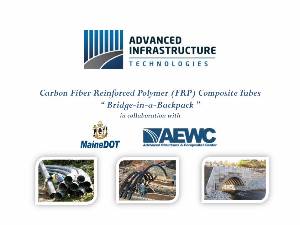
Carbon Fiber Reinforced Polymer (FRP) Composite Tubes
“ Bridge-in-a-Backpack ”in collaboration with
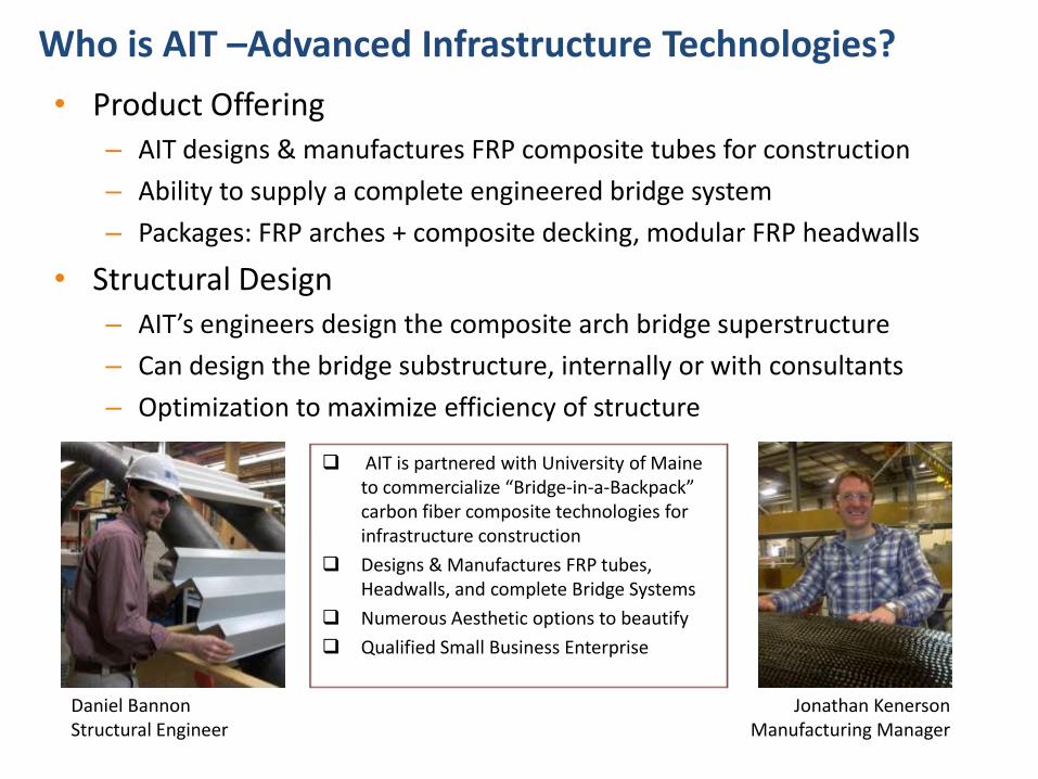
Who is AIT –Advanced Infrastructure Technologies?
AIT is partnered with University of Maine to commercialize “Bridge-in-a-Backpack” carbon fiber composite technologies for infrastructure construction
Designs & Manufactures FRP tubes, Headwalls, and complete Bridge Systems
Numerous Aesthetic options to beautify
Qualified Small Business Enterprise
• Product Offering– AIT designs & manufactures FRP composite tubes for construction
– Ability to supply a complete engineered bridge system
– Packages: FRP arches + composite decking, modular FRP headwalls
• Structural Design– AIT’s engineers design the composite arch bridge superstructure
– Can design the bridge substructure, internally or with consultants
– Optimization to maximize efficiency of structure
Daniel BannonStructural Engineer
Jonathan KenersonManufacturing Manager

What is “Bridge-in-a-Backpack” ? Composite + Concrete Arch Superstructure System
Image Credit – NY Times/University of Maine
“ A hybrid bridge superstructure system combining the strength and longevity of high-performance composites with durability and cost savings of cast-in-place concrete ”
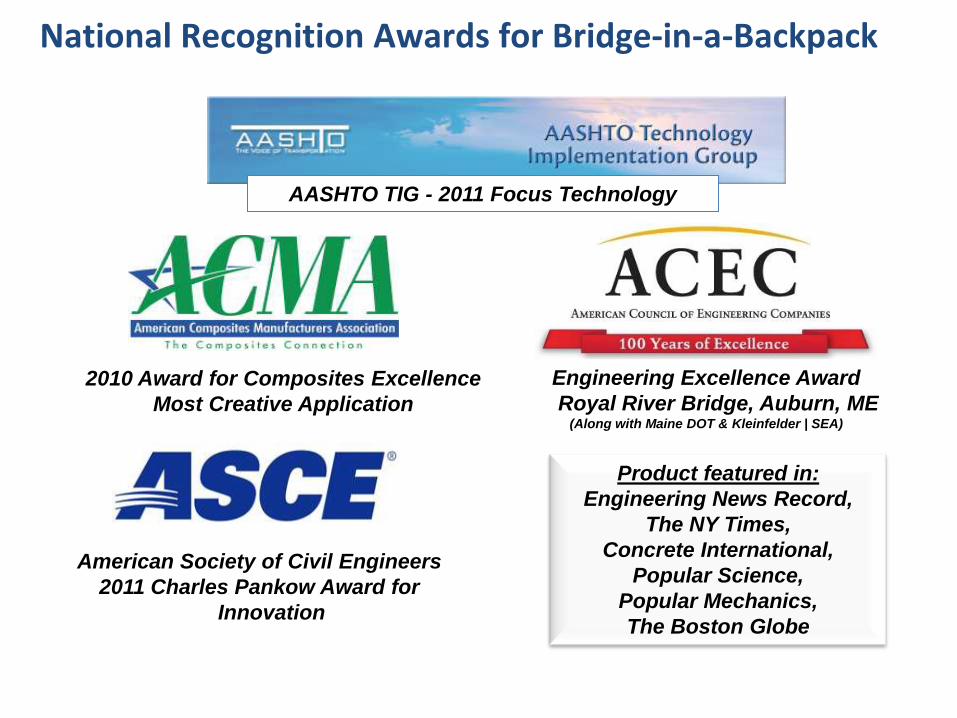
National Recognition Awards for Bridge-in-a-Backpack
Engineering Excellence Award
Royal River Bridge, Auburn, ME(Along with Maine DOT & Kleinfelder | SEA)
AASHTO TIG - 2011 Focus Technology
Product featured in:
Engineering News Record,
The NY Times,
Concrete International,
Popular Science,
Popular Mechanics,
The Boston Globe
American Society of Civil Engineers
2011 Charles Pankow Award for
Innovation
2010 Award for Composites Excellence
Most Creative Application
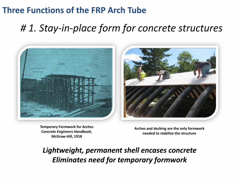
Three Functions of the FRP Arch Tube
# 1. Stay-in-place form for concrete structures
Arches and decking are the only formwork needed to stabilize the structure
Temporary Formwork for Arches Concrete Engineers Handbook,
McGraw-Hill, 1918
Lightweight, permanent shell encases concreteEliminates need for temporary formwork
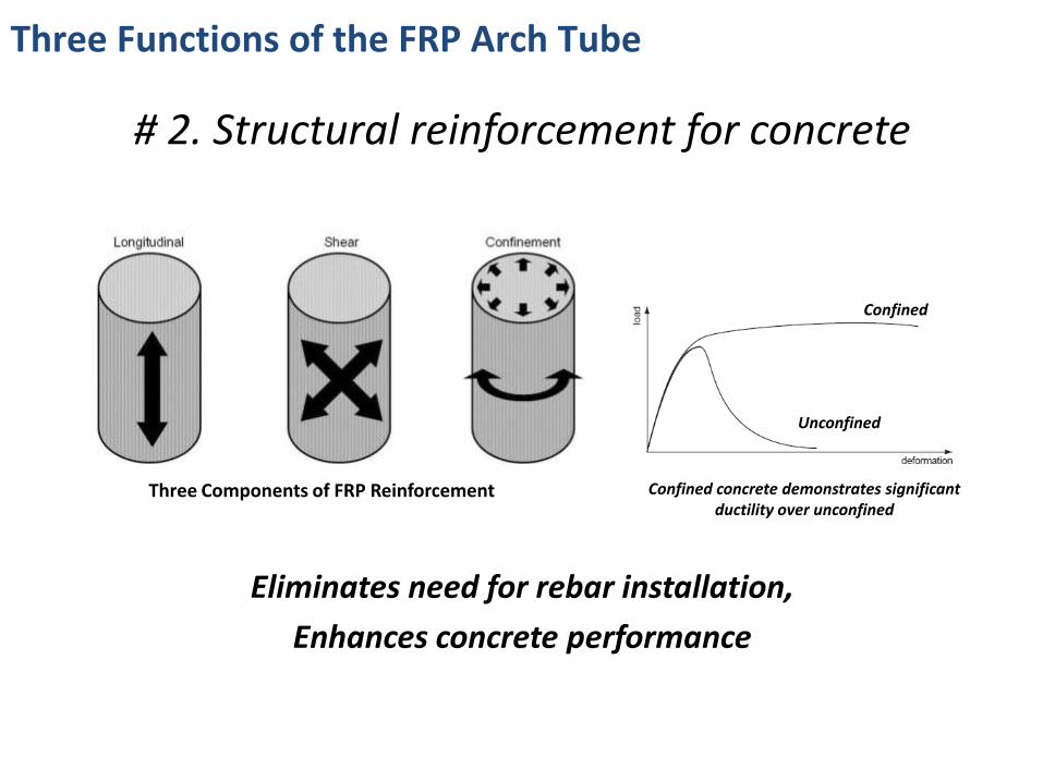
# 2. Structural reinforcement for concrete
Eliminates need for rebar installation,
Enhances concrete performance
Three Components of FRP Reinforcement Confined concrete demonstrates significant ductility over unconfined
Confined
Unconfined
Three Functions of the FRP Arch Tube
Three Functions of the FRP Arch Tube
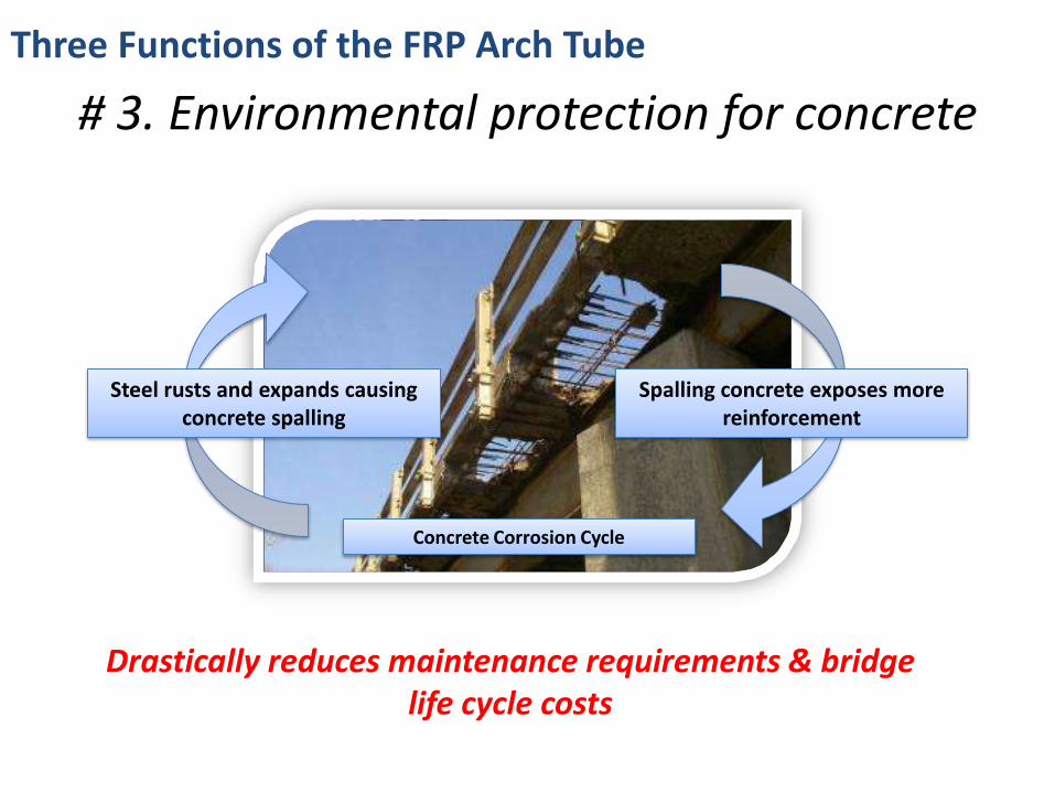
# 3. Environmental protection for concrete
Concrete Corrosion Cycle
Steel rusts and expands causing concrete spalling
Spalling concrete exposes more reinforcement
Drastically reduces maintenance requirements & bridge life cycle costs
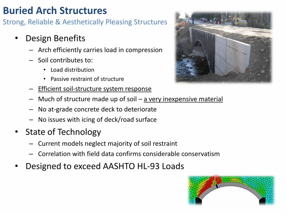
Buried Arch StructuresStrong, Reliable & Aesthetically Pleasing Structures
• Design Benefits– Arch efficiently carries load in compression
– Soil contributes to:
• Load distribution
• Passive restraint of structure
– Efficient soil-structure system response
– Much of structure made up of soil – a very inexpensive material
– No at-grade concrete deck to deteriorate
– No issues with icing of deck/road surface
• State of Technology– Current models neglect majority of soil restraint
– Correlation with field data confirms considerable conservatism
• Designed to exceed AASHTO HL-93 Loads
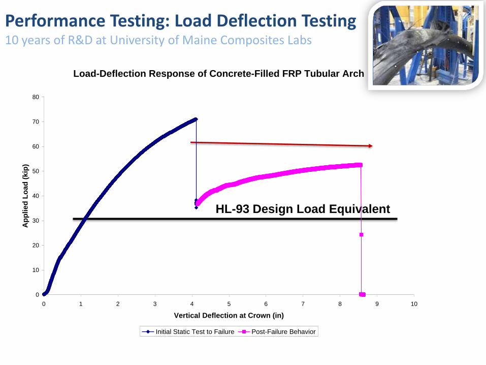
Performance Testing: Load Deflection Testing10 years of R&D at University of Maine Composites Labs
HL-93 Design Load Equivalent
Load-Deflection Response of Concrete-Filled FRP Tubular Arch
0
10
20
30
40
50
60
70
80
0 1 2 3 4 5 6 7 8 9 10
Vertical Deflection at Crown (in)
Ap
pli
ed
Lo
ad
(k
ip)
Initial Static Test to Failure Post-Failure Behavior

Performance Testing: Arch Response / Capacity TestingSafety First, Exceeds HL-93 Design Loads, Double Redundancy, No Catastrophic Failures
Failure Load (kip) COV No. Percent Diff.
InitialExperimental 72.0 2.55% 3
4.14%
Predicted 69.0 -------- --------
SecondaryExperimental 57.6 7.75% 3
1.10%
Predicted 57.0 -------- --------
Load-Deflection Response of Concrete-Filled FRP Tubular Arch
0
10
20
30
40
50
60
70
80
0 1 2 3 4 5 6 7 8 9 10
Vertical Deflection at Crown (in)
Ap
pli
ed
Lo
ad
(k
ip)
Initial Static Test to Failure Post-Failure Behavior
Experimental & Predicted Capacity
Initial hinge at crown
Subsequent hinges at shoulders
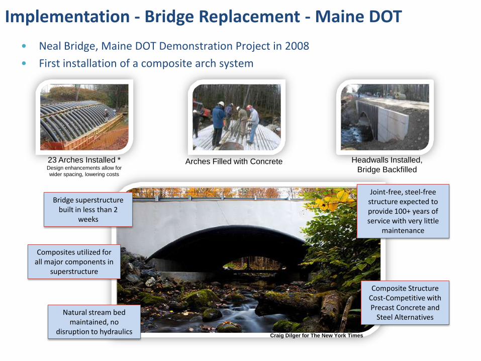
Implementation - Bridge Replacement - Maine DOT
• Neal Bridge, Maine DOT Demonstration Project in 2008
• First installation of a composite arch system
23 Arches Installed * Design enhancements allow for
wider spacing, lowering costs
Headwalls Installed,
Bridge BackfilledArches Filled with Concrete
Bridge superstructure built in less than 2
weeks
Composite Structure Cost-Competitive with Precast Concrete and
Steel Alternatives
Composites utilized for all major components in
superstructure
Joint-free, steel-free structure expected to provide 100+ years of service with very little
maintenance
Natural stream bed maintained, no
disruption to hydraulicsCraig Dilger for The New York Times
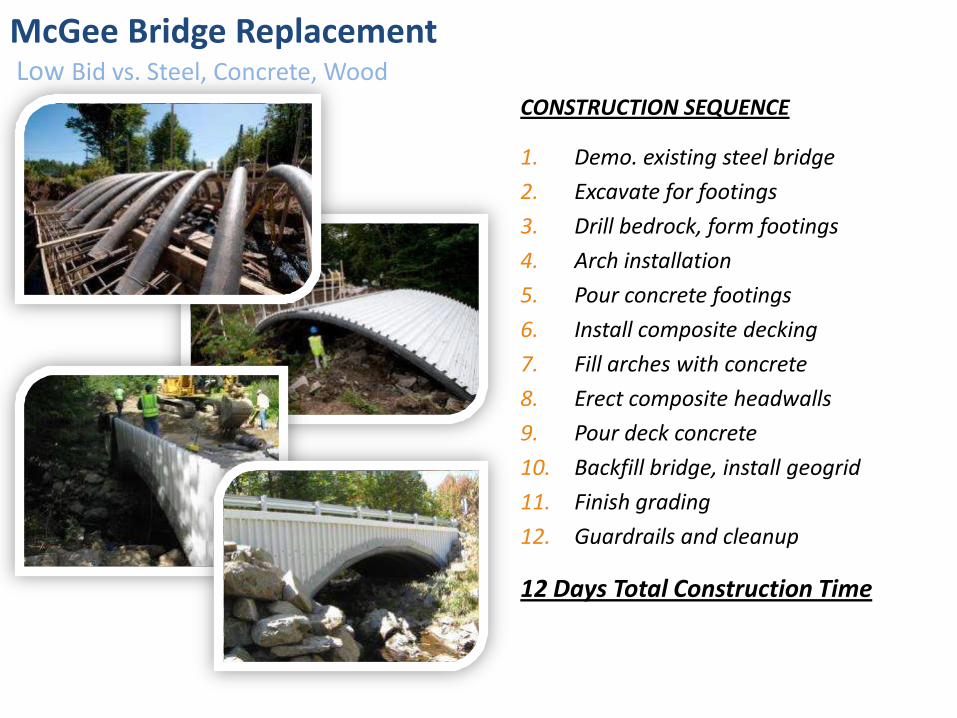
McGee Bridge ReplacementLow Bid vs. Steel, Concrete, Wood
CONSTRUCTION SEQUENCE
1. Demo. existing steel bridge
2. Excavate for footings
3. Drill bedrock, form footings
4. Arch installation
5. Pour concrete footings
6. Install composite decking
7. Fill arches with concrete
8. Erect composite headwalls
9. Pour deck concrete
10. Backfill bridge, install geogrid
11. Finish grading
12. Guardrails and cleanup
12 Days Total Construction Time
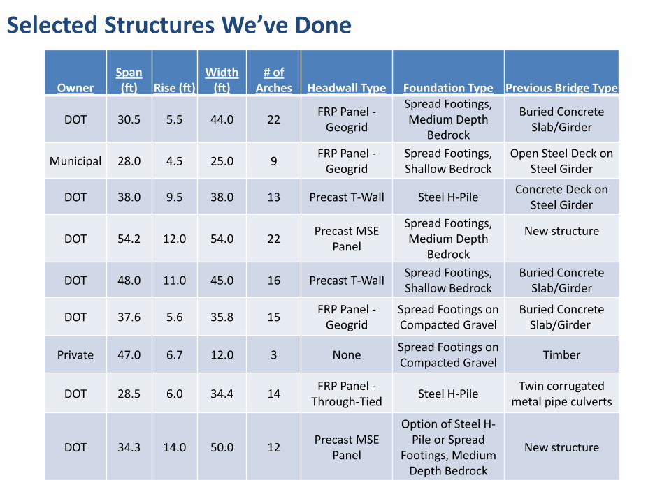
Selected Structures We’ve Done
OwnerSpan (ft) Rise (ft)
Width (ft)
# of Arches Headwall Type Foundation Type Previous Bridge Type
DOT 30.5 5.5 44.0 22FRP Panel -
Geogrid
Spread Footings, Medium Depth
Bedrock
Buried Concrete Slab/Girder
Municipal 28.0 4.5 25.0 9FRP Panel -
GeogridSpread Footings, Shallow Bedrock
Open Steel Deck on Steel Girder
DOT 38.0 9.5 38.0 13 Precast T-Wall Steel H-PileConcrete Deck on
Steel Girder
DOT 54.2 12.0 54.0 22Precast MSE
Panel
Spread Footings, Medium Depth
Bedrock
New structure
DOT 48.0 11.0 45.0 16 Precast T-WallSpread Footings, Shallow Bedrock
Buried Concrete Slab/Girder
DOT 37.6 5.6 35.8 15FRP Panel -
GeogridSpread Footings on Compacted Gravel
Buried Concrete Slab/Girder
Private 47.0 6.7 12.0 3 NoneSpread Footings on Compacted Gravel
Timber
DOT 28.5 6.0 34.4 14FRP Panel -
Through-TiedSteel H-Pile
Twin corrugated metal pipe culverts
DOT 34.3 14.0 50.0 12Precast MSE
Panel
Option of Steel H-Pile or Spread
Footings, Medium Depth Bedrock
New structure
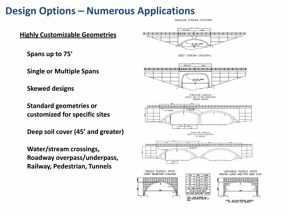
Highly Customizable Geometries
• Spans up to 75’
• Single or Multiple Spans
• Skewed designs
• Standard geometries or customized for specific sites
• Deep soil cover (45’ and greater)
• Water/stream crossings, Roadway overpass/underpass, Railway, Pedestrian, Tunnels
Design Options – Numerous Applications
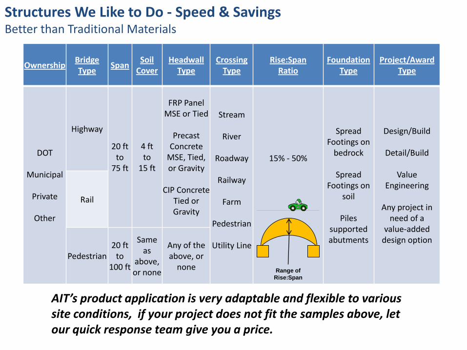
Structures We Like to Do - Speed & SavingsBetter than Traditional Materials
OwnershipBridgeType
SpanSoil
CoverHeadwall
TypeCrossing
TypeRise:Span
RatioFoundation
TypeProject/Award
Type
DOT
Municipal
Private
Other
Highway
20 ftto
75 ft
4 ftto
15 ft
FRP Panel MSE or Tied
PrecastConcrete
MSE, Tied, or Gravity
CIP Concrete Tied or Gravity
Stream
River
Roadway
Railway
Farm
Pedestrian
Utility Line
15% - 50%
Spread Footings on
bedrock
Spread Footings on
soil
Piles supported abutments
Design/Build
Detail/Build
Value Engineering
Any project in need of a
value-added design option
Rail
Pedestrian20 ft
to100 ft
Same as
above,or none
Any of the above, or
none
AIT’s product application is very adaptable and flexible to various site conditions, if your project does not fit the samples above, let our quick response team give you a price.
Range of
Rise:Span
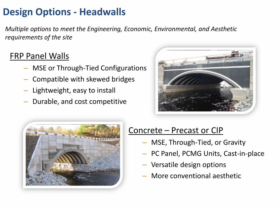
Design Options - Headwalls
FRP Panel Walls– MSE or Through-Tied Configurations
– Compatible with skewed bridges
– Lightweight, easy to install
– Durable, and cost competitive
Multiple options to meet the Engineering, Economic, Environmental, and Aesthetic requirements of the site
Concrete – Precast or CIP– MSE, Through-Tied, or Gravity
– PC Panel, PCMG Units, Cast-in-place
– Versatile design options
– More conventional aesthetic
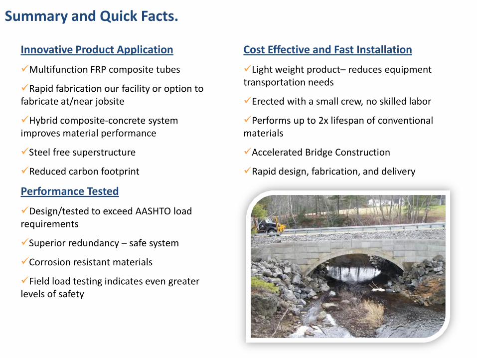
Summary and Quick Facts.
Innovative Product Application
Multifunction FRP composite tubes
Rapid fabrication our facility or option to fabricate at/near jobsite
Hybrid composite-concrete system improves material performance
Steel free superstructure
Reduced carbon footprint
Performance Tested
Design/tested to exceed AASHTO load requirements
Superior redundancy – safe system
Corrosion resistant materials
Field load testing indicates even greater levels of safety
Cost Effective and Fast Installation
Light weight product– reduces equipment transportation needs
Erected with a small crew, no skilled labor
Performs up to 2x lifespan of conventional materials
Accelerated Bridge Construction
Rapid design, fabrication, and delivery
Please contact us for more infowww.aitbridges.com
Daniel J. Bannon
Structural Engineer
(207) 866-6526 x 126
Barry L. Raeburn
EVP - COO
(207) 866-6526 x 134


![Frp tubes [2010]](https://static.fdocuments.net/doc/165x107/549350e8ac79591d2e8b47da/frp-tubes-2010.jpg)