
Carbon Dioxide Post-Combustion Capture: Solvent Technologies Overview...
12
Carbon Dioxide Post-Combustion Capture: Solvent Technologies Overview, Status and Future Directions Mohammad R. M. Abu-Zahra 1,* , Zeina Abbas 1 , Prachi Singh 2 , Paul Feron 3 1 Masdar Institute of Science and Technology, P.O. Box 54224, Abu Dhabi, United Arab Emirates 2 IEA Greenhouse Gas R&D Programme, Orchard Business Centre, Stoke Orchard, Cheltenham GL52 7RZ, UK 3 CSIRO Energy Technology, P. O. Box 330, Newcastle, NSW 2300, Australia *Corresponding author: [email protected] , +9712 810 9181 Keywords: CO 2 post-combustion capture; chemical absorption; amines; pilot plants 1. Introduction One of the most promising approaches to tackle the high emission rate of carbon dioxide is the use of Carbon Capture and Storage (CCS) technology. This technology aims at capturing carbon dioxide from power stations and other industrial facilities, compressing, and then transporting it to underground storage locations. Three technological routes for carbon capture from power plants exist: pre-combustion, post-combustion and oxy- combustion. Pre-combustion is the removal of the carbon element from fuel gas prior to combustion [1]. This process takes place in Integrated Gasification Combined Cycle (IGCC) plants and operates at high pressures for high concentrations of CO 2 . IGCC plants still face several obstacles to commercialization. For instance, only two IGCC demonstration plants are in operation in the power sector in the United States. The second option is oxy-fuel combustion, which involves the use of high purity oxygen (instead of air) for fuel combustion and produces a CO 2 /H 2 O stream from which water is easily condensed [2]. However, the air (or nitrogen-oxygen) separation step is considered a bottle-neck for this process due to its energy intensiveness and high capital and operational costs. Finally, post- combustion capture involves a highly energy intensive nitrogen-carbon dioxide separation step [3]. As an end-of-pipe technology, this process is easier to implement compared to the other capture routes. In this chapter, the focus will be placed on post-combustion capture technology due to its high maturity, ability to be retrofitted to existing power plants and operational flexibility in switching between capture and no-capture modes [4]. 2. Post-Combustion Capture Post-combustion capture (PCC) is the separation of low concentration CO 2 (typically 3-15 %) from flue gas and the production of a relatively pure CO 2 stream, which is then compressed to a pressure of approximately 110 bar and transported via pipelines to be stored in geological formations or used for other applications, such as Enhanced Oil Recovery (EOR). Although PCC incurs high costs making commercialization difficult, it is viewed as the best available technology for CO 2 capture, specifically for coal-fired power plants, mainly due to its maturity level, high CO 2 selectivity and retrofit-ability to the power plants [5]. Several separation technologies can be employed within the PCC category, including: adsorption, cryogenics, membranes and absorption [6]. Comparative assessment studies [[8]-[10]] have shown that the absorption process, specifically based on chemical solvents, is currently the preferred option for post-combustion CO 2 capture. Chemical absorption offers high capture efficiency, high selectivity at low partial pressures, and the lowest energy use and costs when compared with the other separation techniques. For this reason, details on the chemical absorption for post- combustion capture technology only are shown in this chapter. Due to the acidity of CO 2 and the basicity of chemical solvents, a reversible acid–base neutralization reaction takes place upon their interaction in a packed absorber column at a temperature ranging between 40 and 65°C, forming a CO 2 rich solvent while the rest of the flue gas is vented. The rich solvent solution is then pumped to the stripper to regenerate the solvent and separate the CO 2 by increasing the temperature to approximately 90-120 °C using low pressure reboiler steam. Water vapor in the CO 2 product is then condensed, resulting in a highly concentrated (>99%) CO 2 product stream. This stream is liquefied or compressed for transportation to be utilized commercially or stored underground. The regenerated solvent is cooled to absorption temperature (at 40–65 °C) and is recycled back into the absorption column [11]. Chemical absorption based PCC, using monoethanolamine (MEA) solvent, was first commercially employed in the 1970s for use in EOR operations and commercial applications, such as carbonation of brine and production of dry ice, urea and beverages [[12]-[13]]. However, the largest capacity of CO 2 recovered in these applications was approximately ten times less than that of a typical 500 MW coal-fired power plant [14]. Although development of solvents was made more than 80 years ago for CO 2 separation in natural gas processing applications, several studies have shown that amine-based absorption systems are the most suitable option for CO 2 Materials and processes for energy: communicating current research and technological developments (A. Méndez-Vilas, Ed.) ____________________________________________________________________________________________________ ©FORMATEX 2013 923
Transcript of Carbon Dioxide Post-Combustion Capture: Solvent Technologies Overview...
Carbon Dioxide Post-Combustion Capture: Solvent Technologies Overview, Status and Future Directions
Mohammad R. M. Abu-Zahra1,* , Zeina Abbas1, Prachi Singh2, Paul Feron3 1 Masdar Institute of Science and Technology, P.O. Box 54224, Abu Dhabi, United Arab Emirates
2 IEA Greenhouse Gas R&D Programme, Orchard Business Centre, Stoke Orchard, Cheltenham GL52 7RZ, UK 3CSIRO Energy Technology, P. O. Box 330, Newcastle, NSW 2300, Australia
*Corresponding author: [email protected], +9712 810 9181
Keywords: CO2 post-combustion capture; chemical absorption; amines; pilot plants
1. Introduction
One of the most promising approaches to tackle the high emission rate of carbon dioxide is the use of Carbon Capture and Storage (CCS) technology. This technology aims at capturing carbon dioxide from power stations and other industrial facilities, compressing, and then transporting it to underground storage locations. Three technological routes for carbon capture from power plants exist: pre-combustion, post-combustion and oxy-combustion. Pre-combustion is the removal of the carbon element from fuel gas prior to combustion [1]. This process takes place in Integrated Gasification Combined Cycle (IGCC) plants and operates at high pressures for high concentrations of CO2. IGCC plants still face several obstacles to commercialization. For instance, only two IGCC demonstration plants are in operation in the power sector in the United States. The second option is oxy-fuel combustion, which involves the use of high purity oxygen (instead of air) for fuel combustion and produces a CO2/H2O stream from which water is easily condensed [2]. However, the air (or nitrogen-oxygen) separation step is considered a bottle-neck for this process due to its energy intensiveness and high capital and operational costs. Finally, post-combustion capture involves a highly energy intensive nitrogen-carbon dioxide separation step [3]. As an end-of-pipe technology, this process is easier to implement compared to the other capture routes. In this chapter, the focus will be placed on post-combustion capture technology due to its high maturity, ability to be retrofitted to existing power plants and operational flexibility in switching between capture and no-capture modes [4].
2. Post-Combustion Capture
Post-combustion capture (PCC) is the separation of low concentration CO2 (typically 3-15 %) from flue gas and the production of a relatively pure CO2 stream, which is then compressed to a pressure of approximately 110 bar and transported via pipelines to be stored in geological formations or used for other applications, such as Enhanced Oil Recovery (EOR). Although PCC incurs high costs making commercialization difficult, it is viewed as the best available technology for CO2 capture, specifically for coal-fired power plants, mainly due to its maturity level, high CO2 selectivity and retrofit-ability to the power plants [5]. Several separation technologies can be employed within the PCC category, including: adsorption, cryogenics, membranes and absorption [6]. Comparative assessment studies [[8]-[10]] have shown that the absorption process, specifically based on chemical solvents, is currently the preferred option for post-combustion CO2 capture. Chemical absorption offers high capture efficiency, high selectivity at low partial pressures, and the lowest energy use and costs when compared with the other separation techniques. For this reason, details on the chemical absorption for post-combustion capture technology only are shown in this chapter. Due to the acidity of CO2 and the basicity of chemical solvents, a reversible acid–base neutralization reaction takes place upon their interaction in a packed absorber column at a temperature ranging between 40 and 65°C, forming a CO2 rich solvent while the rest of the flue gas is vented. The rich solvent solution is then pumped to the stripper to regenerate the solvent and separate the CO2 by increasing the temperature to approximately 90-120 °C using low pressure reboiler steam. Water vapor in the CO2 product is then condensed, resulting in a highly concentrated (>99%) CO2 product stream. This stream is liquefied or compressed for transportation to be utilized commercially or stored underground. The regenerated solvent is cooled to absorption temperature (at 40–65 °C) and is recycled back into the absorption column [11]. Chemical absorption based PCC, using monoethanolamine (MEA) solvent, was first commercially employed in the 1970s for use in EOR operations and commercial applications, such as carbonation of brine and production of dry ice, urea and beverages [[12]-[13]]. However, the largest capacity of CO2 recovered in these applications was approximately ten times less than that of a typical 500 MW coal-fired power plant [14]. Although development of solvents was made more than 80 years ago for CO2 separation in natural gas processing applications, several studies have shown that amine-based absorption systems are the most suitable option for CO2
Materials and processes for energy: communicating current research and technological developments (A. Méndez-Vilas, Ed.)____________________________________________________________________________________________________
©FORMATEX 2013 923
separation from flue gas emitted from power plants [15]. However, the commercialization of this technology faces major obstacles: intensive solvent regeneration energy, huge absorption towers and high solvent losses and degradation. These obstacles call for the need of developing more economical and efficient solvent systems. Typically, a good solvent candidate should have high CO2 loading with fast kinetics to reduce plant sizes. It should also require low heat of regeneration for the process to be energy efficient. Moreover, it should have high selectivity and high solubility for CO2, so as to avoid reactions with the other impurities in the flue gas stream. Furthermore, it must have low byproduct formation and low decomposition rates to maintain solvent performance and to limit the amount of solvent makeup and waste materials produced. Significant research efforts are being directed at developing improved solvents to be able to commercialize chemical absorption technology for carbon capture from flue gas [[16]-[19]].
3. Amine Solvents Used for Chemical Absorption
3.1 Types, structures and reaction mechanisms
Common amine solvents used in industry for CO2 separation include simple alkanolamines and sterically hindered amines. Simple alkanolamines can be divided into three groups: primary, secondary and tertiary amines. Each of these groups has a different reaction rate with respect to CO2 absorption. In addition, they vary in their equilibrium absorption characteristics and have different sensitivities with respect to solvent stability and corrosion factors [20]. In general, primary and secondary amines react rapidly with CO2 to form carbamates through several principal reactions [21]:
2H2O ↔ H3O+ + OH-
CO2 + 2H2O ↔ HCO3- + H3O
+ RNH2 + H3O
+ ↔ RNH3+
RNH2 + CO2 ↔ RNHCOO- + H3O+
However, due to the additional heat of absorption associated with the formation of carbamate ions, the regeneration energy requirement for primary and secondary amines is higher compared to tertiary or other amines which do not form carbamates [20]. Primary and secondary amines also have the disadvantage of requiring two moles of amine to react with one mole of CO2; thus, their loadings are limited to 0.5 mol of CO2/mol of amine [22]. The most commonly used primary amine in chemical absorption is MEA and that of secondary amines is diethanolamine (DEA). On the other hand, tertiary amines lack the N−H bond required to form the carbamate ion and therefore do not react directly with CO2. However, in aqueous solutions, tertiary amines promote the hydrolysis of CO2 to form bicarbonate and a protonated amine, but with much slower kinetics than those of primary and secondary amines [23]. Another advantage of using tertiary amines is that one mole of amine is needed to react with one mole of CO2, which indicates higher equilibrium CO2 loading than primary and secondary amines [22]. The most frequently used tertiary amine in industry is methyldiethanolamine (MDEA). Cyclic diamines have been suggested as a possible improvement to MEA for capturing CO2, such as concentrated piperazine (PZ). This amine has faster kinetics, higher capacity and higher resistance to oxidative and thermal degradation than MEA [[24]-[25]]. Its loading is approximately 1 mol CO2/mol PZ [26]. The chemical reactions that take place between PZ and CO2 are the following [27]:
2PZ + CO2 → PZH+ + PZCOO- 2PZCOO- + CO2 → PZ(COO-)2 + H+PZCOO- PZCOO- + CO2 + H2O → HCO3
- + H+PZCOO-
Sterically hindered amines are primary or secondary amines with bulky alkyl groups attached to the amino group that provide steric hindrance to the amine group from the reacting CO2 [28]. Steric hindrance leads to lowering the initial reaction rate and producing less stable carbamates, which then undergo hydrolysis and form bicarbonates while releasing the free amine. This free amine then reacts with CO2 leading to an overall higher loading [[29]-[30]]. These amines are considered as a breakthrough in the solvent development field due to the combined advantages of primary, secondary and tertiary amines that they offer, including: high CO2 absorption capacity and low heat regeneration requirements [[22], [31]]. Moreover, when compared to other amine solvents, they have lower degradation rate, lower solvent circulation rate, low corrosivity, less solvent losses and thus, lower costs [32]. A disadvantage of sterically hindered amines is the lower reaction kinetics as compared to primary and secondary amines. A common example of sterically hindered amines is 2-amino-2-methyl-1-propanol (AMP).
3.2 Solvents physical and thermodynamic properties
The most extensively used amine in industry for CO2 removal is MEA [15]. It is considered as the least expensive of the other commercial alkanolamines, and has several advantages over them, such as high reactivity, low solvent cost, low
Materials and processes for energy: communicating current research and technological developments (A. Méndez-Vilas, Ed.)____________________________________________________________________________________________________
©FORMATEX 2013924
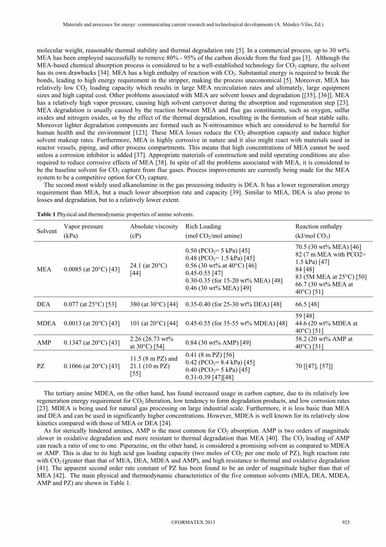
molecular weight, reasonable thermal stability and thermal degradation rate [5]. In a commercial process, up to 30 wt% MEA has been employed successfully to remove 80% - 95% of the carbon dioxide from the feed gas [3]. Although the MEA-based chemical absorption process is considered to be a well-established technology for CO2 capture, the solvent has its own drawbacks [34]. MEA has a high enthalpy of reaction with CO2. Substantial energy is required to break the bonds, leading to high energy requirement in the stripper, making the process uneconomical [5]. Moreover, MEA has relatively low CO2 loading capacity which results in large MEA recirculation rates and ultimately, large equipment sizes and high capital cost. Other problems associated with MEA are solvent losses and degradation [[35], [36]]. MEA has a relatively high vapor pressure, causing high solvent carryover during the absorption and regeneration step [23]. MEA degradation is usually caused by the reaction between MEA and flue gas constituents, such as oxygen, sulfur oxides and nitrogen oxides, or by the effect of the thermal degradation, resulting in the formation of heat stable salts. Moreover lighter degradation components are formed such as N-nitrosamines which are considered to be harmful for human health and the environment [123]. These MEA losses reduce the CO2 absorption capacity and induce higher solvent makeup rates. Furthermore, MEA is highly corrosive in nature and it also might react with materials used in reactor vessels, piping, and other process compartments. This means that high concentrations of MEA cannot be used unless a corrosion inhibitor is added [37]. Appropriate materials of construction and mild operating conditions are also required to reduce corrosive effects of MEA [38]. In spite of all the problems associated with MEA, it is considered to be the baseline solvent for CO2 capture from flue gases. Process improvements are currently being made for the MEA system to be a competitive option for CO2 capture. The second most widely used alkanolamine in the gas processing industry is DEA. It has a lower regeneration energy requirement than MEA, but a much lower absorption rate and capacity [39]. Similar to MEA, DEA is also prone to losses and degradation, but to a relatively lower extent. Table 1 Physical and thermodynamic properties of amine solvents.
Solvent Vapor pressure
(kPa)
Absolute viscosity
(cP)
Rich Loading
(mol CO2/mol amine)
Reaction enthalpy
(kJ/mol CO2)
MEA 0.0085 (at 20°C) [43] 24.1 (at 20°C) [44]
0.50 (PCO2= 5 kPa) [45] 0.48 (PCO2= 1.5 kPa) [45] 0.56 (30 wt% at 40°C) [46] 0.45-0.55 [47] 0.30-0.35 (for 15-20 wt% MEA) [48] 0.46 (30 wt% MEA) [49]
70.5 (30 wt% MEA) [46] 82 (7 m MEA with PCO2= 1.5 kPa) [47] 84 [48] 83 (5M MEA at 25°C) [50] 66.7 (30 wt% MEA at 40°C) [51]
DEA 0.077 (at 25°C) [53] 380 (at 30°C) [44] 0.35-0.40 (for 25-30 wt% DEA) [48] 66.5 [48]
MDEA 0.0013 (at 20°C) [43] 101 (at 20°C) [44] 0.45-0.55 (for 35-55 wt% MDEA) [48] 59 [48] 44.6 (20 wt% MDEA at 40°C) [51]
AMP 0.1347 (at 20°C) [43] 2.26 (26.73 wt% at 30°C) [54]
0.84 (30 wt% AMP) [49] 58.2 (20 wt% AMP at 40°C) [51]
PZ 0.1066 (at 20°C) [43] 11.5 (8 m PZ) and 21.1 (10 m PZ) [55]
0.41 (8 m PZ) [56] 0.42 (PCO2= 8.4 kPa) [45] 0.40 (PCO2= 5 kPa) [45] 0.31-0.39 [47][48]
70 [[47], [57]]
The tertiary amine MDEA, on the other hand, has found increased usage in carbon capture, due to its relatively low regeneration energy requirement for CO2 liberation, low tendency to form degradation products, and low corrosion rates [23]. MDEA is being used for natural gas processing on large industrial scale. Furthermore, it is less basic than MEA and DEA and can be used in significantly higher concentrations. However, MDEA is well known for its relatively slow kinetics compared with those of MEA or DEA [24]. As for sterically hindered amines, AMP is the most common for CO2 absorption. AMP is two orders of magnitude slower in oxidative degradation and more resistant to thermal degradation than MEA [40]. The CO2 loading of AMP can reach a ratio of one to one. Piperazine, on the other hand, is considered a promising solvent as compared to MDEA or AMP. This is due to its high acid gas loading capacity (two moles of CO2 per one mole of PZ), high reaction rate with CO2 (greater than that of MEA, DEA, MDEA and AMP), and high resistance to thermal and oxidative degradation [41]. The apparent second order rate constant of PZ has been found to be an order of magnitude higher than that of MEA [42]. The main physical and thermodynamic characteristics of the five common solvents (MEA, DEA, MDEA, AMP and PZ) are shown in Table 1.
Materials and processes for energy: communicating current research and technological developments (A. Méndez-Vilas, Ed.)____________________________________________________________________________________________________
©FORMATEX 2013 925

4. Amine-Based Commercial Processes
In the period between year 1978 and year 2000, at least a dozen commercial CO2 capture plants were commissioned worldwide, ranging in size from 90 to 1200 ton/day CO2 [58]. In 1978, Kerr-McGee and ABB Lummus installed a 20 wt% MEA system to capture 800 ton/day CO2 from boilers firing a mix of coal and petroleum coke at Kerr-McGee’s soda ash plant in Trona, California USA, for delivering CO2 for soda ash and liquid CO2 preparations [38]. Typically, about 75% to 90% of the CO2 is captured using this technology, producing a nearly pure (>99%) CO2 product stream. Two other commercial plants were operated, with capacities of 200 and 300 tons/day of CO2 from coal boilers in 1991 using this technology [59]. Dow Chemical and Union Carbide developed 30 wt% MEA processes for recovering CO2 from a gas boiler primarily for EOR applications [[60], [61]]. Using this technology, a large CO2 capture plant, which recovered 1200 ton/day CO2 sourcing from natural gas processing, was built in Lubbuck, Texas USA. It only operated for two years (1982-84) before being shut down as low crude oil prices rendered EOR uneconomical. Other smaller scale commercial plants were then built and operated using this technology in China, India and Australia between years 1985 and 1988. This process was then acquired by Fluor Daniel Inc. from Dow Chemical Company in 1989 and renamed to Econamine FG. This process is capable of capturing 85-95% of CO2 and producing 99.95+% pure CO2 product (dry basis), and has been employed by many plants worldwide recovering up to 320 ton CO2 per day for use in beverage and urea production predominantly from flue gases from gas firing. Fluor Daniels’ second generation Econamine FG Plus technology, introduced in 2003, claimed significant reductions in energy consumption (2.95 GJ/ton CO2), but at the expense of increased complexity and capital cost [[62], [63]]. Since 1990, the Kansai Electric Power Co. (KEPCO) and Mitsubishi Heavy Industries, Ltd. (MHI) have jointly conducted research and development of a new CO2 capture technology for CO2 recovery from power plant boiler flue gas and gas turbine exhaust, using patented proprietary sterically hindered amines designated as KS-1, KS-2 and KS-3 [[7], [19], [64]]. They claim that their process is the most energy efficient of the commercial offerings, and experiences low amine losses and low solvent degradation without the use of inhibitors or additives. In addition, it was claimed to require 20% less regeneration heat with less corrosion and amine degradation [14]. The first commercial MHI KM-CDR (Kansai Mitsubishi Carbon Dioxide Recovery) process plant was commissioned in Malaysia in 1999 with a capacity of 200 ton CO2 per day, where flue gas containing 8 vol % CO2 is being treated with 90% recovery. Another nine commercial plants have been commissioned and are operating for gas-fired plants using the KM-CDR technology during the period of 2005-2012, with capacities ranging from 240 to 450 tons/day of CO2 recovered. Tests are currently being conducted at the pilot scale on coal-fired flue gas [[65], [66]]. Solvent compositions of KS-1, KS-2, and KS-3 have been described by Mimura et al. [19]. KS-1 is claimed to have 40% less solvent circulation rate, 20% less regeneration energy, 90% less solvent degradation, 90% less solvent losses and 65% less corrosion than that of MEA [67]. 1.22 tons of low-pressure steam per ton CO2 recovered was consumed using KS-1 solvent [68]. With further process improvements, this figure is expected to be lowered to 0.85-1.0 ton of steam per ton of CO2. It is also claimed that KS-3 is better than KS-1 and KS-2 in terms of energy consumption for solvent regeneration [64]. Another important carbon capture facility is the CO2 Technology Centre Mongstad (TCM), which is a joint venture between the Norwegian state, Statoil, Shell and South African company Sasol [69]. It is the world’s largest CO2 capture test facility and was launched in mid-2012. It is also the only centre to test two different types of technology applicable to emissions from both coal-fired and natural gas power plants. Flue gas from a Residual Catalyst Cracker (RCC) and Combined Heat and Power Plant (CHP) is being provided to the capture facility. Two technology suppliers were also selected to initially run the capture process, being Aker Clean Carbon amine technology and Alstom’s chilled ammonia technology. This facility has a capacity of capturing 100,000 tons of CO2 per year [70]. Cansolv Technologies Inc. CO2 capture process is based on a recently developed amine system using a proprietary solvent named DC101 [71]. This solvent is based on tertiary amine formulations, likely promoted with piperazine and/or its derivatives, to yield sufficient absorption rates and can be used for low pressure flue gas streams [72]. With the use of oxidation inhibitors, this process can be applied to oxidizing environments and where limited concentrations of oxidized sulfur exist. It is claimed that this process can also simultaneously remove other acidic contaminants and particulate material, such as SOx, and NOx. In order to optimize the balance between capital cost and operating cost for a given facility, Cansolv now offers two variants of its second generation CO2 capture solvent, DC-103 and DC-103B. DC-103 is kinetically slower, thus requires a larger absorber, but less regeneration heat. DC-103 is claimed to reduce operating cost, while DC-103B reduces capital cost. For these solvents absorption rates comparable to MEA are claimed, with a 40% reduction in regeneration energy. In addition to very low degradation rates compared to MEA, degradation products retain scrubbing capacity. Two demonstration plants of the Cansolv CO2 capture system have already been built; one in Montreal, Canada, for capture of CO2 from flue gas of a natural gas fired boiler, and one in Virginia, for CO2 capture from flue gas of a coal fired boiler [66]. Cansolv is also partnering with Saskpower, Fluor, Hitachi, Babcock&Wilcox Canada, Neill and Gunter Ltd. and Air Liquide to commission a demonstration carbon capture plant at Boundary Dam power station in Saskatchewan, Canada with a capacity of one million tons CO2 per year using amine solvent [73]. This plant is planned to start operation in 2014. HTC Purenergy have also developed a series of proprietary designer solvents designated as PSR solvents, through research performed at the International Test Centre (ITC) at the University of Regina, Saskatchewan, Canada [74].
Materials and processes for energy: communicating current research and technological developments (A. Méndez-Vilas, Ed.)____________________________________________________________________________________________________
©FORMATEX 2013926
These solvents are claimed to have higher CO2 working capacities than MEA, ranging from 20-80%, and can be used at higher amine concentration. The key features claimed for the PSR solvents are lower regeneration temperature, lower solvent circulation rate, lower solvent degradation rate and lower corrosion rate. Relative energy requirements are reportedly 55-85% of conventional amines. The ability to regenerate PSR solvents at temperatures 5-10°C (9-18°F) lower than that of MEA not only reduces amine degradation, but potentially facilitates process integration by permitting the use of lower pressure steam [74]. The PSR process is being tested on a 4 ton/day CO2 capture facility at the Sask Power 875 MW lignite fired Boundary Dam Power Station under the auspices of the ITC, a consortium of 13 industrial and governmental organizations including two Canadian Universities. Although post combustion carbon capture has been demonstrated commercially in large scale, the CO2 containing feed stream to the capture process is mainly emitted from industrial processes. There is a need for commercial scale plants that treat flue gas from power plants. However, achieving this goal faces obstacles such as high cost and high solvent losses. For this reason, research efforts have been going on in order to develop suitable amine solvents (both single solvent systems and blended amines) which can make the commercialization of post combustion carbon capture feasible.
5. Ongoing Research Efforts
5.1 Single Solvent Systems
Dugas and Rochelle [75] studied the CO2 absorption/desorption of MEA and PZ in a wetted wall column, and the results showed that 8 m PZ had a 75% greater CO2 capacity than 7 m MEA. Also, using PZ showed double to triple the absorption rate of that of MEA. In a similar work, Freeman and Rochelle [55] found the CO2 absorption rate of aqueous PZ to be more than double of that of 7 m MEA, with negligible thermal degradation up to a temperature of 150 ºC. The Rochelle group at Texas University has established that concentrated PZ is a superior solvent with twice the capacity and CO2 absorption rate of 30 wt % MEA and excellent thermal and oxidative stability [76]. Aroonwilas and Veawab [77] studied AMP and it was more efficient in terms of CO2 removal than DEA by 9% at 0.40 mol/mol CO2 loading, and placed next to MEA based on absorption performance. Yeh et al. [52] found that 20 wt% MEA has a higher rate of absorption (around 1.5 times more) than 29.2 wt% AMP for the same type of packing, but a lower regeneration rate (around 1.8 times less) than AMP. Chowdhury et al. [78] have studied several new hindered amine solvents; seven secondary and two tertiary amine based CO2 solvents were synthesized with systematic modification of their chemical structures by an appropriate placement of substituent functional groups, especially the alkyl functions, relative to the position of the amino group. At least three solvents were found to have faster absorption rates and lower heats of reaction compared to AMP and MDEA. In their previous work, Chowdhury et al. [79] found several high performance tertiary amines with high absorption rates and low heats of reaction compared to MDEA. Traditionally, amines with higher absorption rates are found to exhibit higher heats of reaction, but in Chowdhury and RITE’s studies [84], the tertiary amines showed inverse trends. On the other hand, Singh et al. [80] investigated the structural effects of alkanolamines on CO2 absorption rate and cyclic capacity. The CO2 absorption capacity (for most absorbents) increased while the absorption rate decreased as the chain length between the functional group and the amine group increased. However, six carbon chain length amines, such as hexadimethylenediamine and hexylamine, showed exceptionally high absorption rate and capacity. Moreover, substitution of alkyl and amine groups increased the absorption rate and capacity while hydroxyl group substitution results in a reduced absorption rate. Dibenedetto and Aresta [81] found that the absorption capacity of diamines was double that of monoamines, and showed better regeneration performances. Jang et al. [82] found that the CO2 loading capacity of aqueous AEPD (2-Amino-2-ethyl-1,3-propanediol) is much higher than that of aqueous MEA. Furthermore, IFP has claimed new amine based solvents “DMX1 and DMX2”, which are demixing solvents, meaning that they characterize a phase separation of the solvent into a CO2 lean phase and a CO2 rich phase. Studies of these solvents have shown that they have comparable CO2 absorption performances compared to standard MEA but lower regeneration energies [83]. Reaction enthalpies of DMX1 and DMX2 solvents were found to be 60 and 63 kJ/mol respectively, whereas that of MEA is approximately 80 kJ/mol. Due to the limitations provided by single solvents and the need for further improvement, blended systems have been approached as they combine the advantages of the amines that are mixed. Studies have been made comparing blends to single solvents and show how improvement is possible in certain characteristics when blending is applied.
5.2 Blended Amine Solvents
Blended amines have been developed and reported to have the ability to combine the relatively high rate of reaction with CO2 of the primary or secondary alkanolamine, with the low heat of reaction with CO2 of the tertiary one, leading to higher rates of absorption and lower heats of regeneration [[7], [85]]. Blended amine solutions also offer the advantage of setting the selectivity of the solvent toward CO2 by thoroughly mixing the amines in varying proportions, which results in an additional degree of freedom for achieving the desired separation for a given gas mixture, and
Materials and processes for energy: communicating current research and technological developments (A. Méndez-Vilas, Ed.)____________________________________________________________________________________________________
©FORMATEX 2013 927

hence, a reduction in capital and operating costs. Investigation of the CO2 absorption and desorption characteristics of different amine blends have been approached by several researchers. For example, Veawab et al. [[74], [86], [87]] studied the absorption characteristics of MEA, DEA, MDEA and their blends and found that the absorption performance and stripping energy requirements are greatest in MEA, followed by DEA and then MDEA, while those of the blended alkanolamines lay between their parent alkanolamines. Additionally, Idem and Veawab [88] reported substantial reduction in energy requirements and modest reduction in circulation rates for MEA/MDEA blends in their studies at two CO2 capture pilot plants, one based on natural gas and the other on coal-fired. An aqueous 4:1 molar ratio MEA/MDEA showed a significant reduction in heat duty compared to an equivalent concentration of aqueous MEA. These results were also confirmed by Huttenhuis et al. [89]. The use of PZ activated aqueous MDEA solutions was first patented by BASF as it proved to be successful when applied to the bulk removal of CO2 in ammonia plants [90]. BASF has also been developing a wide range of advanced amine-based solvents for efficiently recovering CO2 emitted from flue gas [91]. Closmann et al. [92] studied the MDEA/PZ blend in a molality ratio of 7.7 : 1.2. Outcomes of the study showed that the heat of CO2 absorption of the blended solvent is about 75 kJ/mol while that of 7 m MEA is around 84 kJ/mol. MDEA/PZ blend also showed better performance than MEA and MDEA alone for resistance to thermal and oxidative degradation at typical absorption/stripping conditions. The resistance to oxidative degradation was found to be highest in the blend, followed by MDEA and then PZ. Furthermore, Bishnoi and Rochelle [42] reported that 6 M PZ/4 M MDEA blend absorbed CO2 faster than MEA or DEA blends with MDEA at similar concentrations. Park et al. [93] studied the absorption rates of CO2 into aqueous mixtures of MDEA and hexamethylenediamine (HMDA). As the concentration of HMDA increased from 0.7 wt% to 14.4 wt%, the absorption rate constant was increased from 25% to 292% compared with 20.5 wt% MDEA. Han et al. [94] also confirmed a similar effect of HMDA in MEA blends but results showed higher absorption rate and capacity using HMDA/AMP blends. Singh et al. [122] tested HMDEA/AMP blend in a pilot plant for 10 vol% CO2 and found that regeneration energy requirement is lower (3.41 MJ/kgCO2) than that of MEA (4.33 MJ/kg CO2). Furthermore, Mangalapally and Hasse [[95], [96]] have presented high performance new solvents named as CESAR1 and CESAR2. CESAR1 is a mixture of AMP and PZ whereas CESAR2 is a primary amine with two amine groups (1,2- Ethanediamine (EDA)). Their pilot plant results showed that the new solvents require lower flow rates and regeneration energy as compared to standard MEA. For example, CESAR1 requires 20% less regeneration energy and 45% less solvent flow rate than MEA. Currently there is also research and development in the area of amine based solvents in combination with enzymes, which acts as a catalyst to transform carbon dioxide to bicarbonate such as Carbonic Anhydrase. Carbonic Anhydrase is an enzyme found in the blood of humans and other mammals. This enzyme facilitates the transfer of CO2 during respiration. Genetic modification of this enzyme makes it possible to use it in combination with aqueous alkanolamine solutions within an industrial environment, like flue gas treatment [121].
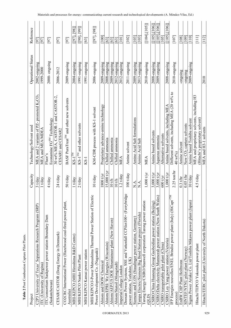
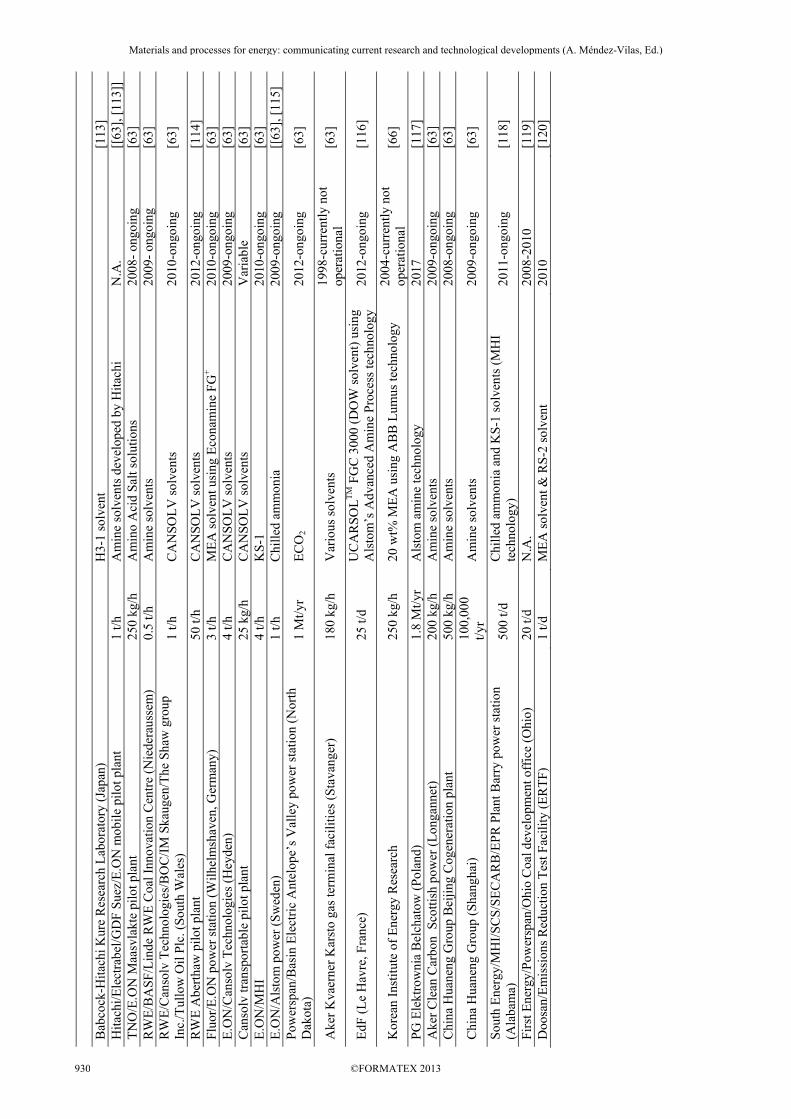
6. Pilot Activities
As a primary step to achieving commercialization for amine based post combustion carbon capture, pilot plants using chemical absorption have been commissioned at several power plants worldwide. Currently, there are numerous pilot scale post-combustion capture plants running worldwide and deploying various forms of amines. Both Research and Development (R&D) institutions and industrial companies have contributed to the establishment of these pilot plants. Major R&D groups include CSIRO, the University of Texas, the University of Regina, NTNU and University of Melbourne. Industrial companies which supply the amine technologies include: Fluor (Econamine FG PlusTM technology), MHI (KM-CDR process), Aker Clean Carbon, BASF (aMDEA technology), Cansolv (Cansolv absorbent DC), Alstom (Chilled Ammonia process), Siemens (PostCap amino acid salt technology), Babcock&Wilcox (Regenerable Solvent Absorption Technology), HTC Purenergy, Toshiba, Powerspan (ECO2®) and Hitachi [63]. The capacity of operating pilot plants ranges between 0.5 to 50 tons/day. The most commonly used solvents in these pilot plants are MEA, KS-1, chilled ammonia, and Cansolv solvents. A list of the pilot activities taking place worldwide is shown in Table 2.
Materials and processes for energy: communicating current research and technological developments (A. Méndez-Vilas, Ed.)____________________________________________________________________________________________________
©FORMATEX 2013928
Tab
le 2
Pos
t Com
bust
ion
Cap
ture
Pil
ot P
lant
s.
Pro
ject
C
apac
ity
Tec
hnol
ogy/
Solv
ent u
sed
Ope
ratio
nal S
tatu
s R
efer
ence
C2P
3 U
nive
rsity
of
Tex
as’
Sep
arat
ions
Res
earc
h P
rogr
am (
SR
P)
3 t/d
ay
ME
A a
nd 2
var
iant
s of
PZ
- pr
omot
ed K
2CO
3 20
02-o
ngoi
ng
[97]
IT
C (
Uni
vers
ity o
f R
egin
a)
1 t/d
ay
ME
A a
nd M
EA
/MD
EA
19
99-2
000
[97]
IT
C/c
onso
rtiu
m S
askp
ower
pow
er s
tatio
n B
ound
ary
Dam
(S
aska
tche
wan
) 4
t/day
F
luor
’s
Eco
nam
ine
FG
SM
Tec
hnol
ogy
2000
- on
goin
g [9
7]
CE
SA
R/C
AST
OR
(D
ong
Ene
rgy
in D
enm
ark)
24
t/da
y 30
wt%
ME
A, C
AS
TO
R-1
and
CA
ST
OR
-2,
CE
SA
R1
and
CE
SA
R2
2006
-201
2 [9
7]
CO
2CR
C/I
nter
nati
onal
Pow
er (
Haz
elw
ood
coal
-fir
ed p
ower
pla
nt,
Aus
tral
ia)
50 t/
day
BA
SF
Pur
aTre
atT
M a
nd o
ther
new
sol
vent
s 20
09-o
ngoi
ng
[97]
MH
I-K
EP
CO
(M
HI
Hir
oshi
ma
R&
D C
entr
e)
1 t/
day
KS
-1T
M20
04-o
ngoi
ng
[[97
], [
98]]
MH
I/K
EP
CO
Nan
ko P
ilot P
lant
2
t/day
K
S-1
TM
and
oth
er s
olve
nts
1991
-ong
oing
[[
98],
[99
]]
MH
I/K
EP
CO
Kan
sai p
ower
sta
tion
K
S-1
19
91-o
ngoi
ng
[63]
MH
I/K
EP
CO
/J-P
ower
Mat
sush
ima
The
rmal
Pow
er S
tati
on o
f E
lect
ric
Pow
er D
evel
opm
ent C
o. (
Nag
asak
i)
10 t/
day
KM
-CD
R p
roce
ss w
ith K
S-1
sol
vent
20
06-o
ngoi
ng
[[97
], [
98]]
Als
tom
and
DO
W C
hem
ical
18
00 t/
yr
Pro
prie
tary
adv
ance
-am
ine
tech
nolo
gy
2009
-ong
oing
[1
00]
A
lsto
m/E
PR
I/ W
e E
nerg
ies
(Wis
cons
in)
15,0
00 t/
yr
Chi
lled
amm
onia
20
08-o
ngoi
ng
[63]
A
lsto
m/A
EP
/US
DO
E M
ount
aine
er p
lant
(N
ew H
aven
) 10
t/h
Chi
lled
amm
onia
20
09-o
ngoi
ng
[63]
A
lsto
m/S
tato
il (M
ongs
tadt
) 10
t/h
Chi
lled
amm
onia
20
12-o
ngoi
ng
[63]
Im
peri
al C
olle
ge L
ondo
n 1.
2 t/d
ay
ME
A
2012
-ong
oing
[1
01]
D
oosa
n P
ower
Sys
tem
s, S
SE
and
Vat
tenf
all C
CP
ilot1
00+
(F
erry
brid
ge
pow
er s
tati
on, Y
orks
hire
, UK
) 10
0 t/d
ay
Am
ine
solv
ent
2011
-ong
oing
[1
02]
Sie
men
s an
d E
.ON
(S
taud
inge
r po
wer
sta
tion,
Ger
man
y)
N.A
. A
min
o A
cid
Sal
t for
mul
atio
ns
2009
-ong
oing
[1
03]
T
ampa
Ele
ctri
c/S
iem
ens
Big
Ben
d S
tatio
n pr
ojec
t (F
lori
da)
N.A
. A
min
o A
cid
Sal
t 20
13-o
ngoi
ng
[103
]
Tar
ong
Ene
rgy/
CS
IRO
/Sta
nwel
l cor
pora
tion
Tar
ong
pow
er s
tatio
n (Q
LD
) 1,
000
t/yr
ME
A
2010
-ong
oing
[[
104]
,[10
5]]
CS
IRO
/Chi
na H
uane
ng G
roup
Gao
beid
ian
pow
er s
tatio
n (B
eiji
ng)
3,00
0 t/y
r A
min
e ba
sed
solv
ents
20
08-o
ngoi
ng
[[10
5],[
106]
]
CS
IRO
/Del
ta e
lect
rici
ty M
unm
orah
pow
er s
tatio
n (N
ew S
outh
Wal
es)
3,00
0 t/y
r A
queo
us a
mm
onia
20
09-o
ngoi
ng
[[10
5],[
106]
] C
SIR
O tr
ansp
orta
ble
pilo
t pla
nt (
Chi
na)
600
t/yr
Alte
rnat
ive
solv
ents
[105
] C
SIR
O L
oy Y
ang
pow
er s
tatio
n (V
icto
ria)
1,
000
t/yr
Am
ine
base
d so
lven
ts, i
nclu
ding
ME
A
2008
-ong
oing
[[
105]
,[10
6]]
IFP
Ene
rgie
s no
uvel
les/
EN
EL
Bri
ndis
i pow
er p
lant
(It
aly)
(H
iCap
t+T
M
proc
ess)
2.
25 to
n/hr
D
iffe
rent
sol
vent
s, in
clud
ing
ME
A (
20 w
t% to
40
wt%
) 20
10-o
ngoi
ng
[107
]
EnB
W C
HP
Pla
nt H
eilb
ronn
0.
3 t/h
r A
min
e so
lven
t -o
ngoi
ng
[108
] S
INT
EF
/NT
NU
pilo
t pla
nt (
Nor
way
) 0.
05 t/
hr
New
CO
2 ca
ptur
e so
lven
ts
-ong
oing
[1
09]
Sig
ma
Pow
er A
riak
e C
o. L
td/T
oshi
ba M
ikaw
a po
wer
pla
nt (
Japa
n)
10 t/
day
Am
ine
base
d T
oshi
ba s
olve
nt
2009
-ong
oing
[1
10]
Hita
chi/T
EP
CO
Yok
osuk
a po
wer
pla
nt
4.5
t/day
M
EA
and
pro
prie
tary
sol
vent
s, in
clud
ing
H3
(Hit
achi
’s p
ropr
ieta
ry s
olve
nt)
[1
11]
Hita
chi/E
ER
C p
ilot p
lant
(U
nive
rsity
of
Nor
th D
akot
a)
M
EA
and
H3-
1 so
lven
ts
2010
[1
12]
Materials and processes for energy: communicating current research and technological developments (A. Méndez-Vilas, Ed.)____________________________________________________________________________________________________
©FORMATEX 2013 929
Bab
cock
-Hita
chi K
ure
Res
earc
h L
abor
ator
y (J
apan
)
H3-
1 so
lven
t
[113
] H
itac
hi/E
lect
rabe
l/G
DF
Sue
z/E
.ON
mob
ile
pilo
t pla
nt
1 t/
h A
min
e so
lven
ts d
evel
oped
by
Hita
chi
N.A
. [[
63],
[11
3]]
T
NO
/E.O
N M
aasv
lakt
e pi
lot p
lant
25
0 kg
/h
Am
ino
Aci
d Sa
lt so
lutio
ns
2008
- on
goin
g [6
3]
RW
E/B
ASF
/Lin
de R
WE
Coa
l Inn
ovat
ion
Cen
tre
(Nie
dera
usse
m)
0.
5 t/h
A
min
e so
lven
ts
2009
- on
goin
g [6
3]
RW
E/C
anso
lv T
echn
olog
ies/
BO
C/I
M S
kaug
en/T
he S
haw
gro
up
Inc.
/Tul
low
Oil
Plc
. (S
outh
Wal
es)
1 t/h
C
AN
SOL
V s
olve
nts
2010
-ong
oing
[6
3]
RW
E A
bert
haw
pilo
t pla
nt
50 t/
h C
AN
SO
LV
sol
vent
s 20
12-o
ngoi
ng
[114
]
Flu
or/E
.ON
pow
er s
tatio
n (W
ilhel
msh
aven
, Ger
man
y)
3 t/h
M
EA
sol
vent
usi
ng E
cona
min
e F
G+
2010
-ong
oing
[6
3]
E.O
N/C
anso
lv T
echn
olog
ies
(Hey
den)
4
t/h
CA
NSO
LV
sol
vent
s 20
09-o
ngoi
ng
[63]
C
anso
lv tr
ansp
orta
ble
pilo
t pla
nt
25 k
g/h
CA
NS
OL
V s
olve
nts
Var
iabl
e [6
3]
E.O
N/M
HI
4 t/h
K
S-1
20
10-o
ngoi
ng
[63]
E
.ON
/Als
tom
pow
er (
Sw
eden
) 1
t/h
Chi
lled
amm
onia
20
09-o
ngoi
ng
[[63
], [
115]
P
ower
span
/Bas
in E
lect
ric
Ant
elop
e’s
Val
ley
pow
er s
tatio
n (N
orth
D
akot
a)
1 M
t/yr
E
CO
2 20
12-o
ngoi
ng
[63]
Ake
r K
vaer
ner
Kar
sto
gas
term
inal
fac
ilitie
s (S
tava
nger
) 18
0 kg
/h
Var
ious
sol
vent
s 19
98-c
urre
ntly
not
op
erat
iona
l [6
3]
EdF
(L
e H
avre
, Fra
nce)
25
t/d
UC
AR
SOL
TM
FG
C 3
000
(DO
W s
olve
nt)
usin
g A
lsto
m’s
Adv
ance
d A
min
e P
roce
ss te
chno
logy
20
12-o
ngoi
ng
[116
]
Kor
ean
Inst
itut
e of
Ene
rgy
Res
earc
h 25
0 kg
/h
20 w
t% M
EA
usi
ng A
BB
Lum
us te
chno
logy
20
04-c
urre
ntly
not
op
erat
iona
l [6
6]
PG
Ele
ktro
wni
a B
elch
atow
(P
olan
d)
1.8
Mt/y
r A
lsto
m a
min
e te
chno
logy
20
17
[117
]
Ake
r C
lean
Car
bon
Sco
ttish
pow
er (
Lon
gann
et)
200
kg/h
A
min
e so
lven
ts
2009
-ong
oing
[6
3]
Chi
na H
uane
ng G
roup
Bei
jing
Cog
ener
atio
n pl
ant
500
kg/h
A
min
e so
lven
ts
2008
-ong
oing
[6
3]
Chi
na H
uane
ng G
roup
(Sh
angh
ai)
100,
000
t/yr
A
min
e so
lven
ts
2009
-ong
oing
[6
3]
Sou
th E
nerg
y/M
HI/
SC
S/S
EC
AR
B/E
PR
Pla
nt B
arry
pow
er s
tatio
n (A
laba
ma)
50
0 t/d
C
hille
d am
mon
ia a
nd K
S-1
sol
vent
s (M
HI
tech
nolo
gy)
2011
-ong
oing
[1
18]
Fir
st E
nerg
y/P
ower
span
/Ohi
o C
oal d
evel
opm
ent o
ffic
e (O
hio)
20
t/d
N.A
. 20
08-2
010
[119
]
Doo
san/
Em
issi
ons
Red
uctio
n T
est F
acili
ty (
ER
TF
)
1 t/d
M
EA
sol
vent
& R
S-2
solv
ent
2010
[1
20]
Materials and processes for energy: communicating current research and technological developments (A. Méndez-Vilas, Ed.)____________________________________________________________________________________________________
©FORMATEX 2013930
7. Conclusions
Amine scrubbing is a proven technology and is ready to be tested and used on large coal-fired power plants. As a tail-end technology, it offers flexibility through implementation in scale-up, on/off operation during peak demand, and can be retrofit to existing utility plants. Other advanced technologies will not provide solutions as energy-efficient or as timely to decrease CO2 emissions. Amongst the different amine solvents used for CO2 separation, 30 wt% MEA has served as the standard for the evaluation of processes for post-combustion capture. However, this solvent needs to be improved due to its drawbacks and other more economically efficient amines need to be developed. Pilot plants have already been built at several power stations to demonstrate the amine based post-combustion chemical absorption process. However, large scale commercialization of this process is yet to be performed. There is a need for full integration of the carbon capture process to power plants. In the direction for large scale CO2 post-combustion capture plants; novel solvents focusing on amine blends together with improved capture process configurations are required. In addition, the capture process integration with the power plant, plant flexibility, process control and the ability to incorporate future process/solvent improvements are essential to have successfully operational capture plant in commercial scale.
References [1] Cormos, C.C., Evaluation of Power Generation Schemes Based on Hydrogen-Fuelled Combined Cycle with Carbon Capture
and Storage (CCS). International Journal of Hydrogen Energy, 2011. 36: p. 3726-3738. [2] Hadjipaschalis, I., G. Kourtis, and A. Poullikkas, Assessment of Oxyfuel Power Generation Technologies. Renewable and
Sustainable Energy Reviews, 2009. 13(9): p. 2637-2644. [3] Metz, B., Davidson, O., de Coninck, H., Loos, M., Meyer, L., IPCC Special Report on Carbon Dioxide Capture and Storage.
2005: Cambridge University Press. [4] Abu Zahra, M.R.M., Carbon Dioxide Post-Combustion Capture: Overview Challenges and Future Directions, in 8th
Engineering Excellence Forum. 2012: Higher Colleges of Technology- Abu Dhabi. [5] GHG, I., CO2 capture as a factor in power station investment decisions. IEA GHG (IEA Greenhouse Gas R&D Programme)
Report, 2006(2006/8). [6] Thiruvenkatachari, R., Su, S., An, H., Yu, X.X.,, Post Combustion CO2 Capture by Carbon Fibre Monolithic Adsorbents.
Progress in Energy and Combustion Science, 2009. 35(5): p. 438-455. [7] White, C.M., , Separation and capture of CO2 from large stationary sources and sequestration in geological formations—
coalbeds and deep saline aquifers. Journal of the Air & Waste Management Association, 2003. 53(6). [8] Hendriks, C., Carbon dioxide removal from coal-fired power plants. 1994: Kluwer. [9] Riemer, P. and W. Ormerod, International perspectives and the results of carbon dioxide capture, disposal, and utilization
studies. Energy Conversion and Management, 1995. 36: p. 813-818. [10] IEAGHG, Leading options for the capture of CO2 emissions at power stations. 2000, IEA Greenhouse Gas R&D Programme. [11] Stewart, C. and M.A. Hessami, A study of methods of carbon dioxide capture and sequestration––the sustainability of a
photosynthetic bioreactor approach. Energy Conversion and Management, 2005. 46(3): p. 403-420. [12] Kaplan, L., Cost-saving process recovers CO2 from power-plant flue gas. Chemical Engineering (NY);(United States), 1982.
89(24). [13] Pauley, C.R., P.L. Simiskey, and S. Haigh, N-Ren Recovers CO2 from Flue Gas Economically. Oil & Gas, 1984. 82(20): p. 87-
92. [14] Herzog, H., An introduction to CO2 separation and capture technologies. Massachusetts Institute of Technology Energy
Laboratory Working Paper, 1999. [15] Shao, R. and A. Stangeland, Health and Environmental Impacts, in Amines Used in CO2 Capture. 2009, The Bellona
Foundation. [16] Zheng, X., Diao, Y.F., He, B.S., Chen, C.H., Xu, X.C., Feng, W., Carbon Dioxide Recovery from Flue Gases by Ammonia
Scrubbing. Greenhouse Gas Control Technologies. 2002. 1: p. 193-197. [17] Cullinane, J.T. and G.T. Rochelle, Carbon dioxide absorption with aqueous potassium carbonate promoted by piperazine.
Chemical Engineering Science, 2004. 59(17): p. 3619-3630. [18] Chakravarti, S., A. Gupta, and B. Hunek. Advanced technology for the capture of carbon dioxide from flue gases. 2001. [19] Mimura, T., et al. Recent developments in flue gas CO2 recovery technology. 2002. [20] Power Plant CCS, Chemical Absorption, in Amine Solvents. 2010. [21] Ramachandran, N., et al., Kinetics of the Absorption of CO2 into Mixed Aqueous Loaded Solutions of Monoethanolamine and
Methyldiethanolamine. Ind. Eng. Chem. Res., 2006. 45: p. 2608-2616. [22] D'Alessandro, D.M., B. Smit, and J.R. Long, Carbon Dioxide Capture: Prospects for New Materials. Ange. Chem. Int. Ed.,
2010. 49: p. 6058-6082. [23] Polasek, J. and J. Bullin, Selecting amines for sweetening units. ENERGY PROGRESS., 1984. 4(3): p. 146-149. [24] Alvis, R.S., N.A. Hatcher, and R.H. Weiland, CO2 Removal from Syngas Using Piperazine-Activated MDEA and Potassium
Dimethyl Glycinate, in Nitrogen+Syngas 2012. 2012: Athens. [25] Chen, X. and G. Rochelle, Aqueous piperazine derivatives for CO2 capture: Accurate screening by a wetted wall column.
Chemical Engineering Research and Design, 2011. 89(9): p. 1693-1710.
Materials and processes for energy: communicating current research and technological developments (A. Méndez-Vilas, Ed.)____________________________________________________________________________________________________
©FORMATEX 2013 931

[26] Moon, S., et al., Heat of reaction for CO2 absorption using aqueous K2CO3 solution with homopiperazine, in Trondheim CCS Conference-6. 2011: Trondheim.
[27] Plaza, J.M. and G. Rochelle, Modeling Pilot Plant Results for CO2 Capture by Aqueous Piperazine. Energy Procedia, 2011(4): p. 1593-1600.
[28] Rameshni, M., Carbon Capture Overview. 2010, WorleyParsons. [29] Chakma, A., Separation of Acid Gases from Power Plant Flue Gas Streams by Formulated Amines. Vansant, EF, Elsevier
Science Publishers, 1994: p. 727-737. [30] Sartori, G. and D.W. Savage, Sterically hindered amines for carbon dioxide removal from gases. Industrial & Engineering
Chemistry Fundamentals, 1983. 22(2): p. 239-249. [31] Rochelle, G., et al., Research needs for CO2 capture from flue gas by aqueous absorption/stripping. Austin, The University of
Texas, 2001. [32] Gupta, M., I. Coyle, and K. Thambimuthu, CO2 Capture Technologies and Opportunities in Canada, in 1st Canadian CC&S
Technology Roadmap Workshop. 2003: Alberta. [33] Xu, S., et al., Kinetics of the Reaction of Carbon Dioxide with 2-Amino-2-Methyl-1-Propanol Solutions. Chemical Engineering
Science, 1996. 51(6): p. 841-850. [34] Aaron, D. and C. Tsouris, Separation of CO2 from flue gas: a review. Separation Science and Technology, 2005. 40(1-3): p.
321-348. [35] Stewart, E. and R. Lanning, Reduce amine plant solvent losses; Part 1. Hydrocarbon Processing;(United States), 1994. 73(5). [36] Strazisar, B.R., R.R. Anderson, and C.M. White, Degradation pathways for monoethanolamine in a CO2 capture facility.
Energy & fuels, 2003. 17(4): p. 1034-1039. [37] Ma’mun, S., et al., Selection of new absorbents for carbon dioxide capture. Energy Conversion and Management, 2007. 48(1):
p. 251-258. [38] Barchas, R. and R. Davis, The Kerr-McGee/ABB Lummus Crest technology for the recovery of CO2 from stack gases. Energy
Conversion and Management, 1992. 33(5-8): p. 333-340. [39] NREL, Survey and Down-Selection of Acid Gas Removal Systems for the Thermochemical Conversion of Biomass to Ethanol
with a Detailed Analysis of an MDEA System, in Task 2: Detailed MDEA Process Analysis. 2009: California. [40] Gupta, M., I. Coyle, and K. Thambimuthu, Strawman Document for CO2 Capture and Storage (CC&S) Technology Roadmap,
in CO2 Capture Technologies and Opportunities in Canada. 2003, CANMET Energy Technology Centre: Alberta. [41] Freeman, S.A., J. Davis, and G. Rochelle, Degradation of Aqueous Piperazine in Carbon Dioxide Capture. International
Journal of Greenhouse Gas Control, 2010. 4(5): p. 756-761. [42] Bishnoi, S. and G.T. Rochelle, Absorption of carbon dioxide into aqueous piperazine: reaction kinetics, mass transfer and
solubility. Chemical Engineering Science, 2000. 55(22): p. 5531-5543. [43] Yu, C., C. Huang, and C. Tan, A Review of CO2 Capture by Absorption and Adsorption. Aerosol and Air Quality Research,
2012. 12: p. 745-769. [44] Kohl, A. and R. Nielson, Gas Purification. 5th ed. 1997, Texas: Gulf Publishing Company. [45] Wagener, D.V. and G. Rochelle, Stripper configurations for CO2 capture by aqueous monoethanolamine and piperazine.
Energy Procedia, 2011. 4: p. 1323-1330. [46] Murai, S., et al., Novel Hindered Amine Absorbent for CO2 Capture, in GHGT-11. 2013, Elsevier: Japan. [47] Sherman, B., et al., Carbon Capture with 4 m Piperazine/4 m 2-Methylpiperazine, in GHGT-11, E. Procedia, Editor. 2013,
Elsevier: Japan. [48] Chemstations, CHEMCAD, in Power Plant Carbon Capture with CHEMCAD. 2009: Houston. [49] Choi, W.-J., et al., Removal characteristics of CO2 using aqueous MEA/AMP solutions in the absorption and regeneration
process. Journal of Environmental Sciences, 2009. 21: p. 907-913. [50] Siminiceanu, I., R.E. Tataru-Farmus, and C. Bouallou, Kinetics of Carbon Dioxide Absorption into Aqueous Solution of a
Polyamine. Chemical bulletin, 2008. 53(67). [51] Kim, S.-T., et al., Analysis of the heat of reaction and regeneration in alkanolamine-CO2 system. Korean J. Chem. Eng., 2011.
28(12): p. 2275-2281. [52] Yeh, J.T., H.W. Pennline, and K.P. Resnik, Study of CO2 absorption and desorption in a packed column. Energy & fuels, 2001.
15(2): p. 274-278. [53] EPA, Diethanolamine, in Hazard Summary. 2000, United States Environmental Protection Agency. [54] Murshid, G., et al., Thermo Physical Analysis of 2-Amino-2-methyl-1-propanol Solvent for Carbon Dioxide Removal. Chemical
Engineering Transactions, 2011. 25. [55] Freeman, S.A., et al., Carbon dioxide capture with concentrated, aqueous piperazine. International Journal of Greenhouse gas
Control, 2010. 4(2): p. 119-124. [56] Rochelle, G., et al., Aqueous piperazine as the new standard for CO2 capture technology. CHEMICAL ENGINEERING, 2011.
171: p. 725-733. [57] Yu, C. and C. Tan, Mixed Alkanolamines with Low Regeneration Energy for CO2 Capture in a Rotating Packed Bed, in
GHGT-11. 2013, Energy Procedia: Japan. [58] Duke, M.C., et al., Assessment of postcombustion carbon capture technologies for power generation. Frontiers of Chemical
Engineering in China, 2010. 4(2): p. 184-195. [59] Herzog, H.J., THE ECONOMICS OF CO2 CAPTURE1. 1999. [60] Sander, M.T. and C.L. Mariz, The Fluor Daniel® econamine FG process: Past experience and present day focus. Energy
Conversion and Management, 1992. 33(5-8): p. 341-348. [61] Chapel, D.G., C.L. Mariz, and J. Ernest, Recovery of CO2 from flue gases: commercial trends. Aliso Viejo, 1999. [62] Freeman, B. and R. Rhudy, Assessment of post-combustion carbon capture technology developments. 2007, Report. [63] Feron, P., et al., Research Opportunities in Post Combustion CO2 Capture. 2009, CSIRO, CO2CRC.
Materials and processes for energy: communicating current research and technological developments (A. Méndez-Vilas, Ed.)____________________________________________________________________________________________________
©FORMATEX 2013932
[64] Mimura, T., et al., Development and application of flue gas carbon dioxide recovery technology. Proceedings of the Fifth Greenhouse Gas Control Technologies, Cairns, Australia, 2000.
[65] Kishimoto, S., et al., Current status of MHI’s CO2 recovery technology and optimization of CO2 recovery plant with a PC fired power plant. Energy Procedia, 2009. 1(1): p. 1091-1098.
[66] Herzog, H., J. Meldon, and A. Hatton, Advanced post-combustion CO2 capture. Clean Air Task Force, 2009. [67] Lecomte, F., P. Broutin, and E. Lebas, CO2 Capture: Technologies to Reduce Greenhouse Gas Emissions, ed. Technip. 2010,
Paris: IFP. [68] MHI. Latest Advancements in Post Combustion CO2 Capture Technology for Coal Fired Power Plant. in Ninth Annual
Conference on Carbon Capture & Sequestration. 2010. Pittsburgh, Pennsylvania: Mitsubishi Heavy Industries, LTD. [69] altenergymag, CO2 Technology Centre Mongstad launches International Carbon Capture and Storage Test Centre Network, in
altenergymag.com. 2013. [70] Norway.cn, Carbon Capture and Storage: Technology Centre Mongstad opened, in Norway.cn. 2012. [71] Cansolv, Cansolv Technologies Inc. 2008. [72] Hakka, L.E. and M.A. Ouimet, Method for recovery of CO2 from gas streams. 2006, Google Patents. [73] MIT, Carbon Capture & Sequestration Technologies @ MIT, in Boundary Dam Fact Sheet: Carbon Dioxide Capture and
Storage Project. 2013. [74] Veawab, A., et al. Solvent formulation for CO2 separation from flue gas streams. 2001. [75] Dugas, R. and G. Rochelle, Absorption and desorption rates of carbon dioxide with monoethanolamine and piperazine. Energy
Procedia, 2009. 1(1): p. 1163-1169. [76] Rochelle, G., Pilot Plant Testing of Advanced Concepts for CO2 Capture by Amines, in The CO2 Capture Pilot Plant Project
(C2P3). 2011, The University of Texas: Austin. [77] Aroonwilas, A. and A. Veawab, Characterization and comparison of the CO2 absorption performance into single and blended
alkanolamines in a packed column. Industrial & engineering chemistry research, 2004. 43(9): p. 2228-2237. [78] Chowdhury, F.A., et al., Synthesis and selection of hindered new amine absorbents for CO2 capture. Energy Procedia, 2011. 4:
p. 201-208. [79] Chowdhury, F.A., et al., Development of novel tertiary amine absorbents for CO< sub> 2</sub> capture. Energy Procedia,
2009. 1(1): p. 1241-1248. [80] Singh, P., J.P.M. Niederer, and G.F. Versteeg, Structure and activity relationships for amine based CO< sub> 2</sub>
absorbents—I. International Journal of Greenhouse gas Control, 2007. 1(1): p. 5-10. [81] Dibenedetto, A., M. Aresta, and R. Girardi, New Amines for Carbon Dioxide Separation from Gas-Mixtures. Fuel Chemistry
Division Preprints, 2003. 48(1): p. 167-168. [82] Jang, K.R., et al. Solubility of Carbon Dioxide in Aqueous Solutions of 2- Amino-2-ethyl-1,3-propanediol. in 7th International
Conference on Greenhouse Gas Control Technologies. 2005. Vancouver, Canada. [83] Carrette, P.L., et al., New Solvent for CO2 Capture with Low Energy of Regeneration. 2007, Innovation Energy Environment. [84] Chowdhury, F.A., Synthesis and Selection of New Amine Absorbents for CO2 Capture, in 1st Post Combustion Capture
Conference. 2011, IEAGHG: Abu Dhabi. [85] Melien, T.C.C.P., Final Cost Estimation and Economics: Common Economic Model Team Summary Report, in Carbon
Dioxide Capture for Storage in Deep Geologic Formations-Results from the CO2 Capture Project. 2005, Elsevier. p. 47-87. [86] Veawab, A., A. Aroonwilas, and P. Tontiwachwuthikul, CO2 ABSORPTION PERFORMANCE OF AQUEOUS
ALKANOLAMINES IN PACKED COLUMNS. 2002. [87] Veawab, A., et al. Performance and cost analysis for CO2 capture from flue gas streams: absorption and regeneration aspects.
2003: Pergamon. [88] Idem, R., D. Gelowitz, and P. Tontiwachwuthikul, Evaluation of the performance of various amine based solvents in an
optimized multipurpose technology development pilot plant. Energy Procedia, 2009. 1(1): p. 1543-1548. [89] Huttenhuis, P.J.G., E.P. Van Elk, and G.F. Versteeg. Performance of Aqueous MDEA Blends for CO2 Removal from Flue
Gases. in 10th Meeting of the International Post-Combustion CO2 Capture Network. 2007. Lyon, France: IEAGHG. [90] Lensen, R., The Promoter Effect of Piperazine on the Removal of Carbon Dioxide. 2004. [91] Jovanovic, S., et al., Slipstream Pilot-Scale Demonstration of a Novel Amine-Based Post-Combustion Technology for Carbon
Dioxide Capture from Coal-Fired Power Plant Flue Gas, in Topical Report: Techno-Economic Analysis of 550 MWe subcritical PC power plant with CO2 capture 2012, Linde LLC: New Jersey.
[92] Closmann, F., T. Nguyen, and G.T. Rochelle, MDEA/Piperazine as a solvent for CO2 capture. Energy Procedia, 2009. 1(1): p. 1351-1357.
[93] Park, S., et al., ABSORPTION RATES OF CO2 INTO AQUEOUS MIXTURES OF MDEA (METHYLDIETHANOLAMINE) AND HMDA (HEXAMETHYLENEDIAMINE). 2005.
[94] Han, K., et al. A Study about Absorption Rate and Capacity of CO2 in Aqueous Mixture of AMP and HMDA. in 8th International Conference on Greenhouse Gas Control Technologies. 2006. Trondheim, Norway: Elsevier Ltd.
[95] Mangalapally, H.P., et al., Pilot plant experimental studies of post combustion CO2 capture by reactive absorption with MEA and new solvents. Energy Procedia, 2009. 1(1): p. 963-970.
[96] Mangalapally, H.P. and H. Hasse, Pilot plant experiments for post combustion carbon dioxide capture by reactive absorption with novel solvents. Energy Procedia, 2011. 4: p. 1-8.
[97] Wang, M., et al., Post-Combustion CO2 Capture with Chemical Absorption: A State-of-the-art Review. Chemical Engineering Research and Design, 2011.
[98] MHI, KM CDR Process, in R and D, Pilot Plant and Engineering Head Quarters. 2012, Mitsubishi Heavy Industries, Ltd. [99] Imai, N. and R. Mitchell, MHI's Experience in Post Combustion CO2 Capture: An Effective Means to Counter Anthropogenic
Global Warming, S.R.E. Forum, Editor. 2008, Mitsubishi Heavy Industries Ltd.: Oslo, Norway. [100] Journal, C.C., Alstom and Dow open CO2 Capture Pilot Plant. 2009.
Materials and processes for energy: communicating current research and technological developments (A. Méndez-Vilas, Ed.)____________________________________________________________________________________________________
©FORMATEX 2013 933
[101] London, I.C., Students Take Control of Four Storey Carbon Capture Pilot Plant in the Heart of a University Campus. 2012: London.
[102] Carrington, D., Largest Carbon Capture Plant in UK opens in Yorkshire, in theguardian. 2011. [103] Siemens, Siemens' Carbon Capture Technology. 2011, Siemens Energy Sector. [104] Stanwell, Post-Combustion Capture Pilot Plant. 2012: Stanwell. [105] CSIRO, Post combustion capture, in Pilot-scale achievements. 2013, CSIRO. [106] Wardhaugh, L., CSIRO Post-Combustion Capture Research – Latest developments and the next steps in NSW. 2010, CSIRO. [107] Bouillon, P.A., et al. First results of the 2.25 t/h post-combustion CO2 capture pilot plant of ENEL at the Brindisi coal power
plant with MEA from 20 to 40 %wt and HiCapt+TM process. in PCCC-1. 2010. [108] Wauschkuhn, A. and S. Unterberger. Post Combustion Capture R&D as part of a utility's strategy for CCS. in 1st IEA GHG
Post Combustion Conference. 2011. Abu Dhabi: EnBW. [109] SINTEF, CO2 Capture Laboratory, in Industrial scale: Develop "Capture Chemicals" of tomorrow. 2013, SINTEF. [110] Suzuki, K., Toshiba's Activity in Clean Coal and Carbon Capture Technology for Thermal Power Plants. 2012, TOSHIBA. [111] Wu, S., et al., Technology Options for Clean Coal Power Generation with CO2 Capture, in XXI World Energy Congress. 2010,
WorldEnergy: Montreal. [112] Kikkawa, H., et al., Hitachi’s Carbon Dioxide Scrubbing Technology with New Absorbent for Coal-fired Power Plants. 2010,
HITACHI. [113] Eswaran, S., et al., Recent Development of Hitachi's Advanced Amine-based Post-Combustion CO2 Capture Technology, P.-G.
2011, Editor. 2011, Hitachi. [114] Matts, D., Aberthaw Carbon Capture Pilot Scale Demonstration. 2012, NPower. [115] MIT, Carbon Capture & Sequestration Technologies @ MIT, in E.ON Karlshamn Fact Sheet: Carbon Dioxide Capture and
Storage Project. 2013. [116] Alstom, EdF, in Le Havre Field Demonstration Plant. 2012. [117] MIT, Carbon Capture & Sequestration Technologies @ MIT, in Belchatow Fact Sheet: Carbon Dioxide Capture and Storage
Project. 2013. [118] MIT, Carbon Capture & Sequestration Technologies @ MIT, in Plant Barry Fact Sheet: Carbon Dioxide Capture and Storage
Project. 2013. [119] MIT, Carbon Capture & Sequestration Technologies @ MIT, in Berger Project Fact Sheet: Carbon Dioxide Capture and
Storage Project. 2013. [120] Elgarni, M. and A. Aboudheir, Design of Commercial Post Combustion CO2 Capture Plant using Pilot Plant Scale-up
Approach, in 1st Post Combustion Capture Conference. 2011: Abu Dhabi. [121] Davy, R., 2009. Development of catalysts for fast, energy efficient post combustion capture of CO2 into water; an alternative to
monoethanolamine (MEA) solvents.Energy Procedia 2009. 1: p. 885–892. [122] Singh, P., et al., Energy Efficient Solvents for CO2 Absorption from Flue Gas: Vapor Liquid Equilibrium and Pilot Plant Study,
in the 11th international conference on greenhouse gas control technologies (GHGT-11). 2012: Kyoto. [123] IEAGHG, Gaseous emissions from amine based PCC processes and their deep removal, Report 2012/07.
Materials and processes for energy: communicating current research and technological developments (A. Méndez-Vilas, Ed.)____________________________________________________________________________________________________
©FORMATEX 2013934


