Carbon Canister Vapor Polisher - vsthose.com
28
Manual No: 577013-920 ● Revision: K Installation and Maintenance Guide Carbon Canister Vapor Polisher 14-i ARB approved IOM 14 - Carbon Canister Vapor Polisher Installation and Maintenance Guide - Executive Order VR-203 and VR-204
Transcript of Carbon Canister Vapor Polisher - vsthose.com

Manual No: 577013-920 ● Revision: K
Installation and Maintenance Guide
Carbon Canister Vapor Polisher
14-iARB approved IOM 14 - Carbon Canister Vapor Polisher Installation and Maintenance Guide - Executive Order VR-203 and VR-204

Notice
Veeder-Root makes no warranty of any kind with regard to this publication, including, but not limited to, the implied warranties ofmerchantability and fitness for a particular purpose.
Veeder-Root shall not be liable for errors contained herein or for incidental or consequential damages in connection with thefurnishing, performance, or use of this publication.
Veeder-Root reserves the right to change system options or features, or the information contained in this publication as approvedby ARB.
This publication contains proprietary information which is protected by copyright. All rights reserved. No part of this publicationmay be modified or translated to another language without the prior written consent of Veeder-Root. Contact TLS SystemsTechnical Support for additional troubleshooting information at 800-323-1799.
DAMAGE CLAIMS / LOST EQUIPMENT
Thoroughly examine all components and units as soon as they are received. If any cartons are damaged or missing, write acomplete and detailed description of the damage or shortage on the face of the freight bill. The carrier's agent must verify theinspection and sign the description. Refuse only the damaged product, not the entire shipment.
Veeder-Root must be notified of any damages and/or shortages within 30 days of receipt of the shipment, as stated in our Termsand Conditions.
VEEDER-ROOT’S PREFERRED CARRIER
1. Contact Veeder-Root Customer Service at 800-873-3313 with the specific part numbers and quantities that were missingor received damaged.
2. Fax signed Bill of Lading (BOL) to Veeder-Root Customer Service at 800-234-5350.3. Veeder-Root will file the claim with the carrier and replace the damaged/missing product at no charge to the customer.
Customer Service will work with production facility to have the replacement product shipped as soon as possible.
CUSTOMER’S PREFERRED CARRIER
1. It is the customer’s responsibility to file a claim with their carrier.2. Customer may submit a replacement purchase order. Customer is responsible for all charges and freight associated with
replacement order. Customer Service will work with production facility to have the replacement product shipped as soon aspossible.
3. If “lost” equipment is delivered at a later date and is not needed, Veeder-Root will allow a Return to Stock without a restockingfee.
4. Veeder-Root will NOT be responsible for any compensation when a customer chooses their own carrier.
RETURN SHIPPING
For the parts return procedure, please follow the appropriate instructions in the "General Returned Goods Policy” pages in the"Policies and Literature" section of the Veeder-Root North American Environmental Products price list. Veeder-Root will notaccept any return product without a Return Goods Authorization (RGA) number clearly printed on the outside of the package.
FOR INSTALLATIONS IN THE STATE OF CALIFORNIA
Please refer to the California Air Resources Board Vapor Recovery Certification Phase II EVR Executive Order web site(www.arb.ca.gov/vapor/eo-evrphaseII.htm) for the latest manual revisions pertaining to Executive Order VR 203 (VST Phase IIEVR System) and VR 204 (VST Phase II EVR System Including ISD System).
©Veeder-Root 2011. All rights reserved.
14-ii ARB approved IOM 14 - Carbon Canister Vapor Polisher Installation and Maintenance Guide - Executive Order VR-203 and VR-204

Table of Contents
IntroductionContractor Certification Requirements ..............................................................................1Related Documents ..........................................................................................................1Safety Precautions ............................................................................................................2Before You Begin ..............................................................................................................4Veeder-Root Parts ............................................................................................................5
Standard Vent Stack Installation Procedure .................................................6
Alternate Vent Stack InstallationsAlternate Vent Stack Installations ...................................................................................13Offset Mount Installations ...............................................................................................14
Flat Mounting..........................................................................................................14
Test Port InstallationStandard Installation Procedure .....................................................................................17Alternate Lowering of the Upper Test Port .....................................................................17
MaintenanceSensor Housing Kit (P/N 330020-644) ...........................................................................18Filter Kit (P/N 330020-645) .............................................................................................19Valve Enclosure Assembly Kit (P/N 330020-643) ...........................................................20Thermal Probe Kit (P/N 330020-653) .............................................................................22
FiguresFigure 1. Typical direct wired installation example ....................................................7Figure 2. Installing CCVP onto bracket .....................................................................8Figure 3. Inlet plumbing detail and classified area definition .....................................9Figure 4. Locating the CCVP vapor valve connector...............................................10Figure 5. Field wiring CCVP vapor valve - direct-wired CCVP only ........................10Figure 6. Epoxy sealing CCVP vapor valve field wiring connections -
direct-wired CCVP only ............................................................................11Figure 7. Attaching CCVP vapor valve wiring to TLS-350 console -
direct-wired CCVP only ............................................................................11Figure 8. Through canopy w/extended plumbing ....................................................13Figure 9. Vent stack mounting.................................................................................13Figure 10. Offset mount on a 2” or 3” pipe ................................................................15Figure 11. Offset mount on a supported riser............................................................16Figure 12. Optional lowering of upper test port .........................................................17Figure 13. Removing sensor housing assembly........................................................18Figure 14. Replacing sensor housing assembly........................................................18Figure 15. Accessing the valve filter and o-ring.........................................................19Figure 16. Replacing the valve filter and o-ring .........................................................19Figure 17. Removing vapor valve assembly..............................................................20Figure 18. Replacing vapor valve assembly..............................................................21Figure 19. CCVP thermal probe ................................................................................22Figure 20. Preparing the thermal probe cable for the protective boot .......................23Figure 21. Positioning the tie wrap over the probe cable’s protective boot ...............23
14-iii ARB approved IOM 14 - Carbon Canister Vapor Polisher Installation and Maintenance Guide - Executive Order VR-203 and VR-204

Table of Contents
TablesTable 1. CCVP 2” Installation Kit .............................................................................5Table 2. CCVP 3” Installation Kit .............................................................................5Table 3. CCVP Replacement Parts Kits ..................................................................5
14-iv ARB approved IOM 14 - Carbon Canister Vapor Polisher Installation and Maintenance Guide - Executive Order VR-203 and VR-204

Introduction
This manual contains instructions to install a Veeder-Root Carbon Canister Vapor Polisher (CCVP) into a gasoline tank vent pipe.
Contractor Certification Requirements
Warranty Registrations may only be submitted by selected Distributors. Certified installers are required to pro-vide the GDF operator with the completed Equipment Warranty Notice, form 577013-868, for their records.
Related Documents
576013-879 TLS-3XX Series Consoles Site Prep Manual
577013-949 In-Station Diagnostics Install, Setup & Operation Manual
577013-948 Pressure Management Control Install, Setup and Operation Manual
576013-858 Direct Burial Cable Installation Guide
577013-964 TLS RF Wireless 2 System (W2) Installation Manual
331940-012 TLS RF System Control Drawing
Veeder-Root Contractor Certification Requirements
Installer Certification6
ATG Technician Certification7
VR Vapor Products Certification8
Install1 ISD X X X
Install PMC X X X
Install CCVP X X X
Install Wireless ISD/PMC X X X
Installation Checkout2 X X
ATG Startup3 / Training4 / Service5 X X
ISD Startup / Training / Service XPMC Startup / Training / Service XCCVP Startup / Training / Service XWireless ISD/PMC Startup / Training / Service X
Install Pressure Sensor (ATG) X X XMaintain Pressure Sensor (ATG) X XCalibrate Pressure Sensor (ATG) X XClear ATG Pressure Sensor Alarm (ATG) X XClear ISD/PMC Alarms (ISD/PMC) X1Perform wiring and conduit touting; equipment mounting 2Inspect wiring and conduit routing; equipment mounting3Turn power on, program and test the systems4Provide supervised field experience in service techniques and operations5Troubleshoot and provide routing maintenance
6UST Monitoring Systems – Installer (Level 1)7Certified UST Monitoring Technician8VR Vapor Products
14-1 ARB approved IOM 14 - Carbon Canister Vapor Polisher Installation and Maintenance Guide - Executive Order VR-203 and VR-204

Introduction Safety Precautions
Safety Precautions
The following safety symbols may be used throughout this manual to alert you to important safety hazards and precautions.
EXPLOSIVEFuels and their vapors are extremely explo-sive if ignited.
FLAMMABLEFuels and their vapors are extremely flammable.
ELECTRICITYHigh voltage exists in, and is supplied to, the device. A potential shock hazard exists.
TURN POWER OFFLive power to a device creates a potential shock hazard. Turn Off power to the device and associ-ated accessories when servicing the unit.
READ ALL RELATED MANUALSKnowledge of all related procedures before you begin work is important. Read and understand all manuals thoroughly. If you do not understand a procedure, ask someone who does.
USE SAFETY BARRICADESUnauthorized people or vehicles in the work area are dangerous. Always use safety cones or barri-cades, safety tape, and your vehicle to block the work area.
WARNINGHeed the adjacent instructions to avoid dam-age to equipment, property, environment or personal injury.
WEAR EYE PROTECTIONWear eye protection when working with pressur-ized fuel lines or epoxy sealant to avoid possible eye injury.
INJURYCareless or improper handling of materials can result in bodily injury.
GLOVESWear gloves to protect hands from irritation or injury.
OFF
14-2 ARB approved IOM 14 - Carbon Canister Vapor Polisher Installation and Maintenance Guide - Executive Order VR-203 and VR-204

Introduction Safety Precautions
WARNINGThis product is to be installed and operated in the highly combustible environment of a gasoline station where flammable liquids and explosive vapors may be present.ATTEMPTING TO SERVICE TANK MONITORS AND EQUIPMENT WITHOUT PROPER TRAINING CAN CAUSE DAMAGE TO PROPERTY, ENVIRONMENT, RESULTING IN PERSONAL INJURY OR DEATH.The following hazards exist:
1. Electrical shock resulting in serious injury or death may result if power is on during installation and the device is improperly installed.
2. Product leakage could cause severe environmental damage or explosion resulting in death, serious personal injury, property loss and equipment damage.
Observe the following precautions:1. Read and follow all instructions in this manual, including all safety warnings.2. Comply with all applicable codes including: the National Electrical Code; federal,
state, and local codes; and other applicable safety codes. 3. Before installing this device, turn Off, tag/lock out power to the system, including
console and submersible pumps. 4. To protect yourself and others from being struck by vehicles, block off your work
area during installation or service.5. Substitution of components may impair intrinsic safety.
OFF
14-3 ARB approved IOM 14 - Carbon Canister Vapor Polisher Installation and Maintenance Guide - Executive Order VR-203 and VR-204

Introduction Before You Begin
Before You Begin
• Comply with all recommended safety practices identified by OSHA (Occupational Safety and Health Administration) and your employer.
• The canister can only be installed in systems with a vapor recovery vent stack fitted with a UL Listed pressure/vacuum (P/V) valve that complies with California Air Resources Board (CARB) requirements and operates between -8 and +6 inches water column. The outlet of the carbon canister vapor valve has the same classified area requirements as the P/V valve per figure 3 and is subject to approval by the local authority having jurisdiction.
• Where separate intrinsically safe circuits are installed in the same raceway they must be segregated in accordance with Article 504 of the NEC.
• Review and comply with all the safety warnings in the installation manuals and any other national, state or local requirements.
• Consult figure 4 along with the National Electrical Code and the compliance section of 576013-879 TLS-3XX Series Consoles Site Prep Manual before installing the CCVP into the hazardous location. If the Carbon Canister is being wired directly to a TLS console, a 2-conductor, 18 AWG shielded cable must be installed in intrinsically safe conduit from the intrinsically safe wiring compartment of the TLS console to the carbon canister. Use of direct burial cable may be subject approval by the local authority having jurisdiction. See manual 576013-858 for a complete listing of required materials and an overview of direct burial installations.
• Use only UL certified Gas/TFE yellow Teflon tape on all fittings. Do not use pipe dope to seal pipe threads or fittings in and out of the CCVP.
• Customer supplied vent riser and vent riser fittings shall be standard full weight (ASTM Schedule 40) wrought iron or steel.
• Vapor polisher installation kit provides either 2" tee (Form Number 861290-002) or 3" reducing tee with busing (Form Number 861290-003) to reduce to 1/2" NPT. Customer supplied reducing tee must not reduce from 2" or 3" to less than 1/2" NPT. If tee reduces to larger than 1/2" use appropriate bushing to reduce the tee to 1/2" NPT.
• For new or rebuilt sites, it is recommended that the installation design specify a threaded fitting for joining the vent pipes to the underground piping system.
• Modification to plumbing in the inlet flow path (i.e., excessive bends) to the CCVP can result in non-compliance with local codes (ARB Exhibit 11 test) and may adversely affect performance if these installation guidelines are not followed. No liquid traps permitted.
• Vent riser threads shall be in accordance with the standard for pipe threads, general purpose (inch) ANSI/ASME B1.20.1-1983.
• The CCVP outlet shall be not less than 12 feet from grade.
• The CCVP outlet shall be located at least 15 feet from powered ventilation air intake devices.
• The CCVP must be mounted vertically.
• The structure to which the CCVP is mounted must be plumb and perpendicular to grade and independently supported and comply with all applicable codes.
• Offset piping and inlet piping to the CCVP shall be installed to avoid bends. No liquid traps permitted.
• Figures and illustrations in this manual represent typical installations and due to site variation, cannot represent all installation situations. Final installation must comply with instructions provided in this manual and all required codes per the jurisdiction having authority.
14-4 ARB approved IOM 14 - Carbon Canister Vapor Polisher Installation and Maintenance Guide - Executive Order VR-203 and VR-204

Introduction Veeder-Root Parts
Veeder-Root Parts
• Veeder-Root Carbon Canister Vapor Polisher, Form No. 861290-002.
• Veeder-Root Carbon Canister Vapor Polisher, Form No. 861290-003.
• Veeder-Root CCVP replacement parts kits. Note: Replacement part kits are not included with new canister assemblies and must be ordered separately, as needed. See the maintenance section of this manual for details.
Table 1. CCVP 2” Installation Kit
Item Qty. Description P/N
1 1 Carbon Canister 332761-002
2 1 Inlet Piping Kit 330020-638
3 1 2” Mounting Bracket Kit 330020-647
4 1 Group - 2” Pipe and Reducing Tee 332954-002
5 1 CCVP Installation Instructions 577013-920
Table 2. CCVP 3” Installation Kit
Item Qty. Description P/N
1 1 Carbon Canister 332761-002
2 1 Inlet Piping Kit 330020-638
3 1 3” Mounting Bracket Kit 330020-648
4 1 Group - 3” Pipe, Reducing Tee & Bushing 332954-003
5 1 CCVP Installation Instructions 577013-920
Table 3. CCVP Replacement Parts Kits
Item Qty. Description P/N
1 1 Valve Enclosure Assembly Kit 330020-643
2 1 Sensor Housing Kit 330020-644
3 1 Filter Kit 330020-645
4 1 Temperature Probe Kit 330020-653
14-5 ARB approved IOM 14 - Carbon Canister Vapor Polisher Installation and Maintenance Guide - Executive Order VR-203 and VR-204

Standard Vent Stack Installation Procedure
1. This procedure requires Veeder-Root installation kits and parts. When using customer provided parts refer also to the alternate vent stack installation procedures.
2. The TLS-3XX Site Prep Manual, P/N 576013-879, must be consulted for the proper installation of a direct-wired carbon canister into hazardous locations. The TLS RF Wireless 2 System (W2) Installation Manual (P/N 577013-964) and document 331940-012, must be consulted for the proper installation of a wireless carbon canister into hazardous locations.
3. During the installation, all required national, state and local safety codes must be followed.
4. The CCVP contains an integral vapor valve that operates in conjunction with the pressure/vacuum (P/V) vent. Location of the vapor valve outlet must conform to the same requirements as the P/V vent. Reference Article 514 of the National Electrical code (NEC) and NFPA 30/30A.
5. Do not install the CCVP on unsupported vent pipes. For all customer supplied supports or strut assemblies, wind loading must comply with all required local, state and national codes and shall be rated for 88 pounds (minimum) static load.
6. IMPORTANT! To ensure that the canister outlet is 12 feet (minimum) above grade, the CCVP mounting bracket must be positioned according to dimensions shown in Figure 1 and the U-bolts tightly clamped to the support structure before mounting the canister. The mounting bracket must be centered in line with the outlet of the tee before installing the CCVP.
7. Following all required national, state, local and site safety precautions, carefully hang the CCVP’s notched support tabs onto the top two side studs of its mounting bracket (Step 1 in Figure 2), swing the canister down until all of the slots in the canister’s side mounting tabs seat against the studs in the bracket (Step 2 in Figure 2), then tighten the six side nuts to secure the canister onto its bracket (Step 3 in Figure 2).
8. Figure 3 shows important Class I Div 1, Group D and Class I Div 2, Group D radius spheres and operability test valve handle positions of the installed canister.
9. For installations using the TLS RF Wireless System, skip to Step 15. For installations using a direct-wired CCVP, go to Step 10.
10. Install weather tight junction box, seal off and conduit per all NEC, state and local codes (see example installation in Figure 1).
11. Connect the two-pin connector of the 6-foot cable provided in the installation kit to the CCVP vapor valve, observing plug polarities (see Figure 4). The other end of this cable is passed through a kit supplied cord grip in the upper junction box.
12. Connect the white wire of the two conductor cable from the vapor valve to the positive sensor wire from the TLS console smart sensor interface module (see Figure 5). Connect the black wire on the two conductor cable to the negative sensor wire from the TLS console smart sensor interface module.
13. Following the instructions in Figure 6, seal the wire nuts of each of the two cable connections in the epoxy pack provided.
14. Attach CCVP vapor valve field wiring to the smart sensor interface module in the TLS console as shown in Figure 7.
15. Connect all lower fittings, valve and tubing between the vent pipe and the lower manifold on the CCVP (see Figure 3).
16. See the Test Port Installation section to install a test port for the Exhibit 12 test.
17. Confirm ball valve is in the open, canister to vent stack position (per Figure 3), then insert the clevis pin and secure with the hitch pin.
18. A passing pressure decay test, in accordance with CARB TP-201.3, must be completed after the CCVP is installed (see Exhibit 4 of VR 203 / VR 204).
19. A passing operability test must be completed in accordance with the procedures defined in VR 203 / VR 204 Exhibit 11 & 12.
14-6 ARB approved IOM 14 - Carbon Canister Vapor Polisher Installation and Maintenance Guide - Executive Order VR-203 and VR-204

Standard Vent Stack Installation Procedure Veeder-Root Parts
Figure 1. Typical direct wired installation example
Canister outletmust be 12 feet
minimumabove grade
2-pin connector of cable (from kit) attaches to CCVP valve
Cord grip (from kit)
Canister supportbracket & fasteners(from kit 330020-647or 330020-648)
P/V assembly(customer supplied)
2" or 3" Sched. 40 upper vent pipe,(from kit or customer supplied)
Grade
Seal off - Install per allNational, State and Localcodes (customer supplied).
Upper J-box - Install per allNational, State and Localcodes (customer supplied).Epoxy enclosed connections in junction box.
Install conduit per allNational, State and Local codes (customer supplied)
18” Min.
2" or 3" to 1/2” NPT Sched. 40 reducing tee and hex bushing (from kit or customer supplied fittings). All pipe andpipe fittings must be schedule 40. All tubefittings must be UL listed and installed per all applicable national, state and local codes and approved by the local authority having jurisdiction.
Vent pipe to support strutfasteners(customer supplied)
2" or 3" lower vent pipe,Sched. 40 (threaded to fit teeif installing 332954-002 or332954-003, customer supplied)
Criticaldimension
Canister supportstuds w/nuts(3 each side)
Centerline of bracket'slowest U-bolt
110"Minimum
Support strut assembly must be independently anchored in concrete. Wind loading and support must comply with applicable codes. (customer supplied)
920-6.eps
14-7 ARB approved IOM 14 - Carbon Canister Vapor Polisher Installation and Maintenance Guide - Executive Order VR-203 and VR-204

Standard Vent Stack Installation Procedure Veeder-Root Parts
Figure 2. Installing CCVP onto bracket
1
2
3
920-7.eps
14-8 ARB approved IOM 14 - Carbon Canister Vapor Polisher Installation and Maintenance Guide - Executive Order VR-203 and VR-204

Standard Vent Stack Installation Procedure Veeder-Root Parts
Figure 3. Inlet plumbing detail and classified area definition
12 feetminimum
above grade(Ref.)
Reducing tee
3 ft.
Clevis pin
Valve handle
Hitch clipValve handle
Handle Position - Canister to AtmosphereHandle Position - Canister to Vent Stack
5 ft.
3 ft.
5 ft.
The 5 foot radius sphereis classified as Class I, Division 2, Group D
The 3 foot radius sphereis classified as Class I, Division 1, Group D
920-1.eps
Inlet Piping Kt (PN 330020-638)
Hazardous location point of origin
for CCVP
14-9 ARB approved IOM 14 - Carbon Canister Vapor Polisher Installation and Maintenance Guide - Executive Order VR-203 and VR-204

Standard Vent Stack Installation Procedure Veeder-Root Parts
Figure 4. Locating the CCVP vapor valve connector
Figure 5. Field wiring CCVP vapor valve - direct-wired CCVP only
Attach 2-pin connectorto CCVP valve connector (other end of cable connects to TLS field wiring in upper j-box)
Carbon Canister
Cable to CCVPthermal probe (factoryinstalled)
920-8.eps
Black
White
ToSmart Sensor
Interface Module2-conductor cableto CC vapor valve
1/2'' rigidconduit
Seal-off
Epoxy sealed connections in aweatherproof junction box920-9.eps
14-10 ARB approved IOM 14 - Carbon Canister Vapor Polisher Installation and Maintenance Guide - Executive Order VR-203 and VR-204

Standard Vent Stack Installation Procedure Veeder-Root Parts
Figure 6. Epoxy sealing CCVP vapor valve field wiring connections - direct-wired CCVP only
Figure 7. Attaching CCVP vapor valve wiring to TLS-350 console - direct-wired CCVP only
920-10.eps
Tie wrap
Wire nuts
A CBMake sure that the ends of the cable sheathing are sub-merged in sealant
INSTRUCTIONS: NOTE: When temperature is below 50°F (10°C), keep resin in a
warm place prior to mixing (e.g., in an inside pocket next to body).1. Open epoxy sealant package, and remove resin pak.2. Holding resin pak as shown in A, bend pak along long length.3. As shown in B, firmly squeeze the RED SIDE of the resin, forcing it through the center seal and into BLACK SIDE.
4. Mix thoroughly to a uniform color by squeezing contents back and forth 25-30 times.
5. Squeeze mixed, warm resin into one end of bag and cutoff other end.
6. Slowly insert wiring connections into sealing pack until they fit snugly against the opposite end as shown in C.
7. Twist open end of bag and use tie wrap to close it off and position the tie wrapped end up until the resin jells.
CAUTION: Epoxy sealant is irritating to eyes, respiratory system, and skin. Can cause allergic skin reaction. Contains: epoxy resin and Cycloaliphatic epoxycarboxylate. Precautions: Wear suitable protective clothing, gloves, eye, and face protection. Use only in well ventilated areas. Wash thoroughly before eating, drinking, or smoking.
920-11.eps
Attach Cable Shields to Ground Lug Closest to Conduit Entry
OR per Control Drawing 331940-012TLS RF Wireless 2 System (W2)
SMARTSENSOR
MAXIMUMOUTPUT RATINGS
13 VDC0.2 AMP
+ + + + + + +1 2 3 4 5 6 7
SMART SENSOR / PRESS MODULE
Rigid Conduit (enters Consolethrough an I.S. Bay knockout)
INTRINSICALLY SAFE BAY OF TLS CONSOLE
+CCVP Valve
14-11 ARB approved IOM 14 - Carbon Canister Vapor Polisher Installation and Maintenance Guide - Executive Order VR-203 and VR-204

Alternate Vent Stack Installations
IMPORTANT!
When a canister is not installed directly to a vent pipe, it is the responsibility of the site owner(s) to:
1. Provide suitably rated mounting locations designed for 88 pounds (minimum) static load.
2. Provide adequate wind loading per all applicable local codes.
3. Follow all recommendations providing an unrestricted flow path into the canister that is free of liquid traps and minimizes the number of bends and turns in the piping. Any departure from the specified installation procedures, must conform to all local code requirements per the jurisdiction having authority.
4. All standard vent stack installation procedures and applicable codes, etc., apply.
Additional requirements are as follows:
• CCVP outlet shall be located not less than 5 feet above the canopy, see NFPA 30: 2008, clause 5.6.3.
• The total length of the tubing (installed horizontally and vertically) between the 3-way valve and the CCVP can not exceed 12 feet. Horizontal lengths shall have a minimum slope of 1/8-inch per foot back to the 3-way valve to drain.
• The horizontal length of tubing between the vent stack and the 3-way valve must not exceed 15 inches. If a horizontal length of more than 15 inches is required, follow the offset riser mounting installation procedures. No liquid traps permitted.
• Customer can supply the following inlet piping materials:
- 5/8" O.D. x 0.065 wall thickness hard temper copper tubing. Alternatively, customer supplied standard full weight (ASTM Schedule 40) wrought iron or steel pipe (1/2" I.D. minimum) can be substituted subject to applicable codes.
- ASTM Schedule 40 wrought iron or steel, 2" or 3" vent riser pipe and pipe fittings
• Vapor Polisher installation kit provides either 2" tee (Form Number 861290-002) or 3" reducing tee with bushing (Form Number 861290-003) to reduce to 1/2" NPT. Customer supplied reducing tee must not reduce from 2" or 3" to less than 1/2" NPT. If tee reduces to larger than 1/2" use appropriate bushing to reduce the tee to 1/2" NPT.
• 3-way valve from the inlet piping kit must be used.
Follow the standard installation procedures when installing vapor polishers in configurations similar those in Figure 8 and Figure 9. All installations of this type must comply with NFPA 30/30A and NFPA 70 and are subject to the approval of the local authority having jurisdiction.
14-12 ARB approved IOM 14 - Carbon Canister Vapor Polisher Installation and Maintenance Guide - Executive Order VR-203 and VR-204

Alternate Vent Stack Installations Alternate Vent Stack Installations
Alternate Vent Stack Installations
Figure 8. Through canopy w/extended plumbing Figure 9. Vent stack mounting
12 ft. Min.from grade
No minimum height (from ground level)
12 ft. Max.
15” Max.
5 ft. Min.from the canopy
920-12.eps
12 ft. Min.from grade
12 ft. Max.
920-13.eps
No minimum height (from ground level)
14-13 ARB approved IOM 14 - Carbon Canister Vapor Polisher Installation and Maintenance Guide - Executive Order VR-203 and VR-204

Alternate Vent Stack Installations Offset Mount Installations
Offset Mount Installations
An offset mount is any installation where the CCVP is not mounted on the P/V vent stack. The CCVP can be mounted to a flat surface, or installed on an offset riser, that is plumbed to the vent stack (see Figure 10 and Figure 11).
The horizontal length of standard inlet piping between the vent stack and the 3-way valve must not exceed 15 inches. If a horizontal length of more than 15 inches is required, use 2-inch minimum pipe. No liquid traps permitted.
The manifold pipe between the vent riser and canister must not exceed 100 feet in length and must be at least 2-inch schedule 40 pipe with no liquid traps present and slope 1/8-inch per foot back to the vent riser to drain. To prevent the CCVP inlet piping from supporting the offset piping weight, provide additional support as required. Offset piping must be capped and comply with applicable local codes.
Flexible connections may be required by local jurisdiction having authority when offset mounting.
Flexible connections between the CCVP's offset piping and the vent riser are allowable if required by the local authority having jurisdiction to meet seismic requirements.
• Should the flex connection be installed such that it is not supported, the slope of the flex connection from the CCVP back to the vent riser shall be greater than the 1/8-inch per foot slope required for the rest of the piping.
• The flexible connector must be UL approved for a service station above-ground application.
• The local contractor is responsible to provide all necessary schedule 40 piping, pipe fittings and pipe cap.
• The Hazardous Location Area Classification shown for the CCVP in Figure 3 must be considered from the point of origin for all offset mountings.
FLAT MOUNTING
1. The bracket in the installation kit must be used.
2. The mounting point must comply with all applicable codes.
3. The mounting method must be sufficiently rated for 88 pounds as per applicable building codes.
4. If bolting the mounting bracket to the mounting surface, use a minimum of 4 bolts.
14-14 ARB approved IOM 14 - Carbon Canister Vapor Polisher Installation and Maintenance Guide - Executive Order VR-203 and VR-204

Alternate Vent Stack Installations Offset Mount Installations
Figure 10. Offset mount on a 2” or 3” pipe
A
A
Support assemblymust be independentlyanchored. Wind loadingand support must complywith applicable codes(customer supplied).
Inlet piping kit(P/N 330020-638)
12 Feetminimum
from grade
Vent pipe
Canister installed on 2” or 3” pipe using supplied mounting bracket kit (P/N 330020-647, or 330020-648 as required)
Offset piping shall be 2-inch minimum; not exceed 100 feet in length; and have a minimum slope of 1/8-inch per foot back to the vent pipe.
Secure offset piping to support structure as per applicable codes.
NOTE: Consult local codes. A flex coupling may be required.
920-21.eps
CCVP intrinsically-safe label location
Customer suppliedschedule 40 pipeand pipe fittings
View A-A
14-15 ARB approved IOM 14 - Carbon Canister Vapor Polisher Installation and Maintenance Guide - Executive Order VR-203 and VR-204

Alternate Vent Stack Installations Offset Mount Installations
Figure 11. Offset mount on a supported riser
Support assembly must be independently anchored. Wind loading and support must comply with applicable codes(customer supplied).
Pipe cap
Inlet piping kit(P/N 330020-638)
12 Feetminimum
from grade
Vent pipe
Customer suppliedschedule 40 pipeand pipe fittings
Canister installed on 2” or 3” riser pipe using sup-plied mounting bracket kit (P/N 330020-647, or 330020-648 as required)
Offset piping shall be 2-inch minimum; not exceed 100 feet in length; and have a minimum slope of 1/8-inch per foot back to the vent pipe.
Secure offset piping to support structure as per applicable codes.
NOTE: Consult local codes. A flex coupling may be required.
920-22.eps
14-16 ARB approved IOM 14 - Carbon Canister Vapor Polisher Installation and Maintenance Guide - Executive Order VR-203 and VR-204

Test Port Installation
Standard Installation Procedure
1. Remove 1/4-inch plug from upper manifold.
2. Install customer supplied schedule 40, 1/4-inch male-to-male with 90 degree elbow NPT fitting by applying Teflon™ tape to the threads and tighten ¼ turn past snug.
3. Install the outlet test port cap by applying Teflon™ tape to the threads and tighten the cap ¼ turn past snug.
4. Perform the CCVP integrity test (VR-203 & VR-204 Exhibit 11).
Alternate Lowering of the Upper Test Port
In some installations it may be desirable to have the upper test port more accessible. The steps below describe this procedure.
1. Refer to Figure 12 to install optional piping necessary to lower the CCVP’s operability (upper) test port.
2. Use schedule 40, 1/4-inch pipe and pipe fittings (customer supplied) - install per all applicable codes.
3. Perform the CCVP integrity test (VR-203 & VR-204 Exhibit 11).
Figure 12. Optional lowering of upper test port
920-4.eps
Anchor upper testport plumbing to asupport structureor to the CCVP nearthe top and bottom(do not anchor to flange rods).
Install plumbing toapprox. same heightas ball valve for convenience. Be sureto replace 1/4” NPT cap after testing. Ensure test port plumbing does not interfere with the 3-way valve operation.
14-17 ARB approved IOM 14 - Carbon Canister Vapor Polisher Installation and Maintenance Guide - Executive Order VR-203 and VR-204
Maintenance
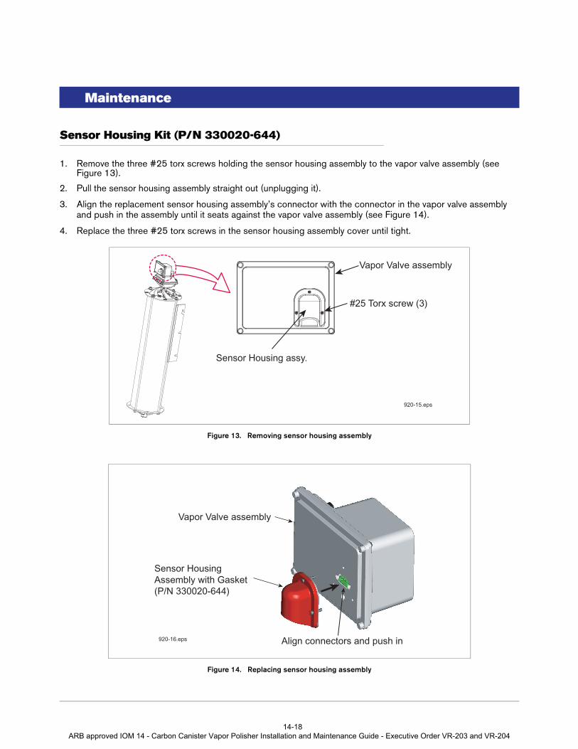
Sensor Housing Kit (P/N 330020-644)
1. Remove the three #25 torx screws holding the sensor housing assembly to the vapor valve assembly (see Figure 13).
2. Pull the sensor housing assembly straight out (unplugging it).
3. Align the replacement sensor housing assembly’s connector with the connector in the vapor valve assembly and push in the assembly until it seats against the vapor valve assembly (see Figure 14).
4. Replace the three #25 torx screws in the sensor housing assembly cover until tight.
Figure 13. Removing sensor housing assembly
Figure 14. Replacing sensor housing assembly
#25 Torx screw (3)
Sensor Housing assy.
Vapor Valve assembly
920-15.eps
Sensor HousingAssembly with Gasket (P/N 330020-644)
Align connectors and push in
Vapor Valve assembly
920-16.eps
14-18 ARB approved IOM 14 - Carbon Canister Vapor Polisher Installation and Maintenance Guide - Executive Order VR-203 and VR-204

Maintenance Filter Kit (P/N 330020-645)
Filter Kit (P/N 330020-645)
1. Remove the four 1/4-20 x 1 inch hex key bolts from the top of the vapor valve filter housing (see Figure 15).
2. Swing the housing top back and remove the filter plate from its seat and the o-ring from its groove in the vapor valve filter housing’s lower half (see Figure 16).
3. Install a new o-ring in the groove and insert a new filter plate into its seat in the lower half of the housing, close the cover and screw in the four 1/4-20 hex key bolts until tight.
4. Perform the CCVP integrity and flow test (VR-203 & VR-204 Exhibit 11).
Figure 15. Accessing the valve filter and o-ring
Figure 16. Replacing the valve filter and o-ring
1/4-20 hex key bolts (4)
Valve filter housing hinged top
920-17.eps
Porous filter plate(P/N 332901-001)
O-ring (P/N 512700-275)
920-18.eps
14-19 ARB approved IOM 14 - Carbon Canister Vapor Polisher Installation and Maintenance Guide - Executive Order VR-203 and VR-204

Maintenance Valve Enclosure Assembly Kit (P/N 330020-643)
Valve Enclosure Assembly Kit (P/N 330020-643)
Figure 17. Removing vapor valve assembly
1. Remove the cables from the two connectors on the rear of the vapor valve assembly.
2. Remove the four 1/4-20 x 1 inch hex key bolts from the top of the vapor valve filter housing (see Figure 17).
3. Remove the hitch clip from the long clevis pin in the front hinge of the vapor valve assembly and vapor valve filter housing (see Figure 18).
4. Push the long clevis pin out and free of the hinge bores and lift up the vapor valve assembly. Be careful not to damage the filter in the vapor valve filter housing.
5. Place the new vapor valve assembly onto the vapor valve filter housing and push the long clevis pin through the hinge bores. Insert the hitch pin in the hole in the end of the clevis pin.
6. Screw in the four 1/4-20 hex key bolts until tight.
7. Reconnect the two cables to the two connectors on the vapor valve assembly.
8. Perform the CCVP integrity and flow test (VR-203 & VR-204 Exhibit 11).
920-19.eps
Carbon Canister
Vapor Valve assembly
Vapor Valve Filter housing
1/4-20 hex key bolts (4)
14-20 ARB approved IOM 14 - Carbon Canister Vapor Polisher Installation and Maintenance Guide - Executive Order VR-203 and VR-204

Maintenance Valve Enclosure Assembly Kit (P/N 330020-643)
Figure 18. Replacing vapor valve assembly
Hitch clip
Clevis pin
Vapor filter
Upper cable (from thermalprobe)
Lower cable(from TLS fieldwiring j-box)
Vapor Filter housing clevis hinge
Vapor Valve Ass’y clevis hinge (2)
Vapor Valve Ass’y
1/4 -20 x 1” hex key bolts (4)
920-3.eps
14-21 ARB approved IOM 14 - Carbon Canister Vapor Polisher Installation and Maintenance Guide - Executive Order VR-203 and VR-204

Maintenance Thermal Probe Kit (P/N 330020-653)
Thermal Probe Kit (P/N 330020-653)
Figure 19. CCVP thermal probe
1. Cut the tie wrap around the thermal probe’s protective boot and remove and set aside the boot. Remove the thermal probe cable connector from the back of the vapor valve assembly (see Figure 19).
2. Using a 9/16-inch open-end wrench, remove the thermal probe from the top of the CCVP.
3. Install and tighten the replacement thermal probe into its port in top of the CCVP.
4. Route the thermal probe connector cable through the opening in the top of the CCVP as shown in the above figure and attach the cable connector to the top port on the rear of the vapor valve assembly.
5. Make a small bend in the thermal probe cable no more than one inch above the probe hex nut (see Figure 20).
6. Slide the boot over the bend of the cable and push it down over the probe’s hex nut until it rests on the top of the CCVP. Get a tie wrap from the kit and position it around the end of the boot just under the probe’s hex nut and tighten it (see Figure 21).
7. Perform the CCVP integrity and flow test (VR-203 & VR-204 Exhibit 11).
Thermal Probe cable’sprotective boot Route cable
through openingin CCVP’s top plate
Thermal Probeconnection
to Vapor Valve
920-31.eps
14-22 ARB approved IOM 14 - Carbon Canister Vapor Polisher Installation and Maintenance Guide - Executive Order VR-203 and VR-204

Maintenance Thermal Probe Kit (P/N 330020-653)
Figure 20. Preparing the thermal probe cable for the protective boot
Figure 21. Positioning the tie wrap over the probe cable’s protective boot
Create a loop in the cableless than 1-inch from the top of the probe’s hex nut
1-inch (25mm) or less
920-32.eps
Position tie wrap around bootend just under the probe’s hex nut
920-33.eps
14-23 ARB approved IOM 14 - Carbon Canister Vapor Polisher Installation and Maintenance Guide - Executive Order VR-203 and VR-204

For technical support, sales orother assistance, please visit:
www.veeder.com
14-24 ARB approved IOM 14 - Carbon Canister Vapor Polisher Installation and Maintenance Guide - Executive Order VR-203 and VR-204