Carbon and Polymer Filaments in Nanoporous Alumina · synthesis and alignment of filamentous...
14
MICROREVIEW DOI: 10.1002/ejic.200501145 Carbon and Polymer Filaments in Nanoporous Alumina Jörg J. Schneider* [a] and Jörg Engstler [a] Keywords: Alumina / Porous templates / Nanotubes / Carbon / Nanochemistry Nanoporous alumina membranes represent templates for the synthesis and alignment of filamentous nanostructured mate- rials. Porous aluminium oxide (PAOX) membranes are ideal for high-temperature synthesis. They are transparent, flexi- ble, freestanding and thermally robust. Their pore sizes can be varied over a wide range. The membrane backside seems suited for structuring processes on the nanoscale, for which it may serve as a master. After introducing the formation pro- 1. Introduction Nanotubes derived from various carbon sources, doped with non-carbon atoms [1] or pure inorganic tubes [2] such as MoS 2 , [3] WS 2 , [4] BN, [5] are intensively studied over the last years because of their unique material properties. Besides the challenge towards the synthesis of such materials, there is also the need to arrange such materials in an organized [a] Fachbereich Chemie, Eduard-Zintl-Institut für Anorganische und Physikalische Chemie, Technische Universität Darmstadt, Petersenstraße 18, 64287 Darmstadt, Germany Fax: +49-6151-16-3470 E-Mail: [email protected] Jörg J. Schneider obtained his diploma and doctoral degree in chemistry at the Philipps-Universität Marburg in 1986, both in the group of Ch. Elschenbroich. After a one-year post doctoral stay in the group of K.J. Klabunde, USA, he joined the Max-Planck-Institut für Kohlenforschung, Mülheim an der Ruhr, in 1988. In 1994 he moved to the University of Essen as lecturer and Heisenberg fellow of the Deutsche Forschungsgemeinschaft. In 2000 he accepted a call as professor of inorganic chemistry at the Karl-Franzens-Universität, Graz, Austria. In 2003 he moved to his current position as professor of inorganic chemistry at the University of Technology, Darmstadt. His research interests are currently oriented towards interdisciplinary aspects of materials synthesis as well as organometallic chemistry. Examples include synthesis and properties of carbon tubes, porous materials, multinuclear metal complexes of condensed aromatics, as well as metal vapour synthesis as a synthetic tool in organometallic and materials chemistry. Jörg Engstler was born in 1973. He studied chemistry at the University of Essen, Germany and obtained his diploma degree in 2000 in the field of synthesis and arrangement of carbon nanotubes. In the same year he moved to the Karl- Franzens-Universität, Graz, Austria, for pursuing his Ph.D. studies in the group of J. J. Schneider. His research activity was focussed on the synthesis and enhancement of field-emission properties of carbon nanotubes in and on porous alumina. In 2003 he received a Dr. rer nat. from the University of Essen. Since 2003, he is a post doc in the groupof J. J. Schneider at TU Darmstadt, Germany. His research interests are in the area of porous nanomaterials, CVD and microscopic characterization techniques. MICROREVIEWS: This feature introduces the readers to the authors’ research through a concise overview of the selected topic. Reference to important work from others in the field is included. Eur. J. Inorg. Chem. 2006, 1723–1736 © 2006 Wiley-VCH Verlag GmbH & Co. KGaA, Weinheim 1723 cess of PAOX membranes, synthesis of carbon nanotubes (CNTs) with different morphologies, their electrical field emission properties, and the formation of polymeric filaments and structured polymer surfaces with the aid of PAOX are reported in this microreview. (© Wiley-VCH Verlag GmbH & Co. KGaA, 69451 Weinheim, Germany, 2006) manner. One important research goal is to synthesize and organize nanomaterials in a single process step that allows for their 1D, 2D, or even 3D arrangement. A common and widely used technique for 2D structuring of nanomaterials is the template process, in which a given form acts as a structure-directing shape to organize individual building blocks in a 2D arrangement. Inorganic templates are typi- cally solid phases; they can be crystalline or amorphous. They are stable with respect to a geometrically defined structure and usually up to higher temperatures. Zeolites are prominent examples of such template types. They enable the organization of matter in a 1D or 3D fashion. Unor- dered inorganic porous structures bearing multiple voids
Transcript of Carbon and Polymer Filaments in Nanoporous Alumina · synthesis and alignment of filamentous...

MICROREVIEW
DOI: 10.1002/ejic.200501145
Carbon and Polymer Filaments in Nanoporous Alumina
Jörg J. Schneider*[a] and Jörg Engstler[a]
Keywords: Alumina / Porous templates / Nanotubes / Carbon / Nanochemistry
Nanoporous alumina membranes represent templates for thesynthesis and alignment of filamentous nanostructured mate-rials. Porous aluminium oxide (PAOX) membranes are idealfor high-temperature synthesis. They are transparent, flexi-ble, freestanding and thermally robust. Their pore sizes canbe varied over a wide range. The membrane backside seemssuited for structuring processes on the nanoscale, for whichit may serve as a master. After introducing the formation pro-
1. Introduction
Nanotubes derived from various carbon sources, dopedwith non-carbon atoms[1] or pure inorganic tubes[2] such asMoS2,[3] WS2,[4] BN,[5] are intensively studied over the lastyears because of their unique material properties. Besidesthe challenge towards the synthesis of such materials, thereis also the need to arrange such materials in an organized
[a] Fachbereich Chemie, Eduard-Zintl-Institut für Anorganischeund Physikalische Chemie, Technische Universität Darmstadt,Petersenstraße 18, 64287 Darmstadt, GermanyFax: +49-6151-16-3470E-Mail: [email protected]
Jörg J. Schneider obtained his diploma and doctoral degree in chemistry at the Philipps-Universität Marburg in 1986,both in the group of Ch. Elschenbroich. After a one-year post doctoral stay in the group of K. J. Klabunde, USA, hejoined the Max-Planck-Institut für Kohlenforschung, Mülheim an der Ruhr, in 1988. In 1994 he moved to the Universityof Essen as lecturer and Heisenberg fellow of the Deutsche Forschungsgemeinschaft. In 2000 he accepted a call asprofessor of inorganic chemistry at the Karl-Franzens-Universität, Graz, Austria. In 2003 he moved to his current positionas professor of inorganic chemistry at the University of Technology, Darmstadt. His research interests are currentlyoriented towards interdisciplinary aspects of materials synthesis as well as organometallic chemistry. Examples includesynthesis and properties of carbon tubes, porous materials, multinuclear metal complexes of condensed aromatics, as wellas metal vapour synthesis as a synthetic tool in organometallic and materials chemistry.
Jörg Engstler was born in 1973. He studied chemistry at the University of Essen, Germany and obtained his diplomadegree in 2000 in the field of synthesis and arrangement of carbon nanotubes. In the same year he moved to the Karl-Franzens-Universität, Graz, Austria, for pursuing his Ph.D. studies in the group of J. J. Schneider. His research activitywas focussed on the synthesis and enhancement of field-emission properties of carbon nanotubes in and on porous alumina.In 2003 he received a Dr. rer nat. from the University of Essen. Since 2003, he is a post doc in the group of J. J. Schneiderat TU Darmstadt, Germany. His research interests are in the area of porous nanomaterials, CVD and microscopiccharacterization techniques.
MICROREVIEWS: This feature introduces the readers to the authors’ research through a concise overview of theselected topic. Reference to important work from others in the field is included.
Eur. J. Inorg. Chem. 2006, 1723–1736 © 2006 Wiley-VCH Verlag GmbH & Co. KGaA, Weinheim 1723
cess of PAOX membranes, synthesis of carbon nanotubes(CNTs) with different morphologies, their electrical fieldemission properties, and the formation of polymeric filamentsand structured polymer surfaces with the aid of PAOX arereported in this microreview.
(© Wiley-VCH Verlag GmbH & Co. KGaA, 69451 Weinheim,Germany, 2006)
manner. One important research goal is to synthesize andorganize nanomaterials in a single process step that allowsfor their 1D, 2D, or even 3D arrangement. A common andwidely used technique for 2D structuring of nanomaterialsis the template process, in which a given form acts as astructure-directing shape to organize individual buildingblocks in a 2D arrangement. Inorganic templates are typi-cally solid phases; they can be crystalline or amorphous.They are stable with respect to a geometrically definedstructure and usually up to higher temperatures. Zeolitesare prominent examples of such template types. They enablethe organization of matter in a 1D or 3D fashion. Unor-dered inorganic porous structures bearing multiple voids

J. J. Schneider, J. EngstlerMICROREVIEWand pores of nonuniform diameters that are randomly dis-tributed in the material are another kind of such a template.Those materials can typically not be used for the controlledorganization of matter in 2D or 3D dimensions, becausetheir pores appear unordered.
For creating filamentous nanomaterials with functionalproperties, for example for optics or electronics applica-tions, a defined 1D orientation of materials and thereforeof the pore structure of the template is essential. Zeolite-based templates like MCM 41, as well as organic-basedtemplates, for example polycarbonate membranes, are use-ful in this regard. However, membrane templates based onorganic materials are often temperature-sensitive, and there-fore high-temperature processes within the membranesoften employed for the synthesis of inorganic nanostruc-tures are impossible with these templates.
Anodic porous aluminium oxide (PAOX) is a valuabletemplate material for high-temperature processes. It iswidely used in the scientific community as a template forsynthesis and organization of nanomaterials.[6] RecentlySchmid has reviewed the synthesis and properties of variousnanoparticle compositions in PAOX.[7] Synthesis, arrange-ment and properties of different rod-shaped magnetic mate-rials in PAOX have been reviewed by Wade.[8] Our contri-bution presented herein is focussed on the generation, prop-erties and 2D arrangement of CNTs and filamentous poly-meric structures, both made by gas-phase processes in andon the surface of PAOX.
2. Nanoporous Anodic Aluminium Oxide asTemplate for Nanofilament Arrangement
The process of electrolytic oxidation of aluminium has along-standing technological relevance and is commerciallyused for surface processing of aluminium for many decades.The pore system of alumina is formed by potentiostatic an-odization, which is characterized by a constant voltage witha current change due to increased resistance in the growingoxide. The morphology of PAOX films synthesized in sulfu-ric acid has been investigated by Keller et al. already in1953.[9] Early studies on the growth mechanism were per-formed by O’Sullivan and Wood in 1970.[10]
Formation and Structure of PAOX
Figure 1 shows a schematic drawing of a PAOX mem-brane with a hexagonally ordered pore system.
The membrane consists of hexagonally ordered cells withone centred pore in each cell. Each cell has a unidirectionalshape orthogonal to the membrane surface. The bottom ofthe pores is sealed by the so-called barrier layer, which con-nects the PAOX membrane with the aluminium metal basefrom which the porous membrane grows in a self-organizedmanner during an ongoing electrochemical oxidation pro-cess. This barrier layer is compact, however it has numerousdefects due to the permanent dissolution by the electrolyte.These defects (channels, pits, voids) are the starting pointsfor regular pore formation in latter stages of the electro-
www.eurjic.org © 2006 Wiley-VCH Verlag GmbH & Co. KGaA, Weinheim Eur. J. Inorg. Chem. 2006, 1723–17361724
Figure 1. Schematic drawing of PAOX with idealized hexagonal or-dered cells (diameter Dc) with a pore (diameter Dp) in the centreof each cell; cross-section (top), view from the top of the pore ar-rangement (bottom).
chemical oxidation. Thus redissolving alumina and ongoingaluminium oxidation are competitive processes (see below).The finally resulting highly ordered PAOX membrane hasa porosity of up to 10% with pore densities of up to 1011
pores per cm2.[11] When a disordered growth is observed,the overall porosity can be significantly lower or higher.[12]
The pore walls of the cells consist of two different types ofalumina.[12] One type is a relatively pure, anion-free, densealumina (dark grey regions in Figure 1, bottom). It buildsup the hexagonal body of the cell. This material is not indirect contact with the open pore space. The inner cell re-gion of the pores consists of a less dense alumina (light greyregions in Figure 1, bottom) contaminated with electrolyteanions (PO4
3– SO42–, C2O4
2–), which forms the pore walland therefore is in direct contact with the electrolyte duringthe electrochemical process. By controlled selective etchingof the backside barrier layer, PAOX membranes with com-plete trough-hole pore morphology can be obtained.
The diameter of the pores (Dp) and the cells (Dc) of aPAOX membrane are dependent on the anodization poten-tial applied in the electrolytic process.[6h,13] Additional ex-perimental parameters governing the pore size are tempera-ture and current density. The latter is influenced by the con-centration and the type of electrolyte used.[11]
PAOX membrane pore diameters between ca. 5–300 nmare so far experimentally accessible. As a rule of thumb, avoltage of 1 V corresponds to a pore growth of ca.

Carbon and Polymer Filaments in Nanoporous Alumina MICROREVIEW1.2 nm.[10] This value depends on anodization conditionsand electrolyte concentration. Figure 2 shows examples ofelectron micrographs of PAOX membranes with varyingpore diameters (Figure 2).
Figure 2. SEM images of freestanding PAOX membranes. Fromupper left to lower right: open front side of a PAOX membranegenerated at 40 V, back side of a PAOX membrane generated at40 V, open front side of a PAOX membrane generated at 25 V, openfront side of a PAOX membrane generated at 8 V.
To obtain PAOX templates with different pore size re-gimes, different electrolytes are used. From 150 to 300 nmH3PO4, from 30 to 70 nm oxalic acid and below 20 nmH2SO4 give reproducible results with respect to pore-sizediameters.[8] This electrolyte dependence of pore size distri-bution is mainly due to the fact that the pore diameter isaffected strongly by the dissolution velocity of alumina inthe electrolyte chosen. The dependence of pore size on elec-trolyte type is, however, complex and involves the dissoci-ation behaviour (pH value, acid/conjugate base equilibrium)and concentration of the electrolyte (e.g. changing the elec-trolyte concentration changes the pH) as the foremost pa-rameters.
The basic membrane-film-forming reaction is dissolutionof the base metal according to
Al(s) �Al3+ + 3e–
Al2O3 is then formed by reaction with O2– ions which aregenerated in the acidic electrolyte medium by the reaction
3/2 H2O � 3 H+ + 3/2 O2–
The formation process of the alumina is accompanied bya local dissolution of the formed alumina due to agitationby protons
1/2 Al2O3(s) + 3 H+(aq) � Al3+(aq) + 3/2 H2O(l)
The latter reaction preferentially occurs at the bottom ofthe formed pores where the electrical field is highest. Thisreaction obviously does not play an important role duringthe initial formation of the compact base oxide layer lyingunderneath the porous layer.
During electrolyte anion incorporation into the growingmembrane, the following reactions occur:[6h]
H3PO4 (aq) � H2PO42– + H+
H2PO4– (aq) � HPO4
2– + H+
Eur. J. Inorg. Chem. 2006, 1723–1736 © 2006 Wiley-VCH Verlag GmbH & Co. KGaA, Weinheim www.eurjic.org 1725
The conjugate divalent base anion HPO42– can replace
O2– in the oxide forming reaction, thus leading to a con-tamination in the growing film. Therefore 6–8 wt.-% PO4
3–
incorporation of the membranes is typically observed whenphosphoric acid is used the electrolyte. Similar percentagesof incorporation are observed for other electrolyte anions(SO4
2–, C2O42–). In contrast, electrolytes which do not form
protonated conjugate bases lead to contamination of freePAOX membranes (e.g. chromic acid[6h]).
The electrochemical process of controlling and downsiz-ing the pore diameter by adjusting the anodization voltageas one of the crucial parameters works well down to poresizes of around 15 nm in the strong electrolyte H2SO4.There is an interest in such nanoporous self-supportingtemplate materials due to their application as nanovesselsfor synthesis and organization of matter on the nanoscale.In the size regime below 15 nm, quantum size effects startto become important for many materials, and a self-sup-porting porous template should make it possible to studyanisotropic effects of such structure-confined materials.However, reports on self-supporting PAOX membraneswith a pore size below ca. 15 nm are scarce. Highly unor-dered PAOX films deposited on glass substrates with smallpore diameters (�10 nm) are known.[14–16] We have studiedpore-size growth of PAOX at anodization voltages down to8 V. Formation of a porous alumina with a pore diameterof about 10 nm results. Handling these PAOX membranesas freestanding templates, however, becomes increasinglydifficult: for example, such membrane templates tend to bebrittle and are mechanically fragile. In contrast, PAOXmembranes with pore sizes between 20 and several 100 nmexhibit good mechanical stability. They are not very fragileand can withstand even moderate mechanical torsion, forexample bending. The reason for this is their cellular struc-ture. It is well known that if pores in a given cellular struc-ture are hexagonally oriented, the mechanical stiffness ofsuch a cellular arrangement decreases roughly by a factorof 50 compared to a similar compact structure.[17] This find-ing is based on the variation of the E-module which is dra-matically affected when comparing a compact with a po-rous structure. In a first approximation, this is regardless ofthe individual material composition of such a structure.
Thus, the high tensile strength of the as-prepared PAOXtemplate relative to a dense, compact alumina film of thesame composition seems mainly due to its mechanical flexi-bility imparted by its regular open porous nature relative tothe dense material of same composition.
3. Carbon Nanotubes and Polymer Fibres inPAOX
3.1 Carbon Nanotubes in PAOX
CNTs Synthesized in PAOX without Catalyst
Spatially arranged CNTs provide a promising materialfor applications in e.g. Li-ion batteries,[18] chemical fil-ters,[19] capacitors,[20] cold field emitting sources[21] or tran-

J. J. Schneider, J. EngstlerMICROREVIEWsistors.[22] PAOX is ideally suited as a template for CNTsynthesis by CVD, a process which typically operates above700 °C.[23–25] The diameter of the CNTs formed inside thePAOX template pores during CVD should be the same asthe PAOX pore diameter. Hence, a general feature ofPAOX, its versatility to control the diameter of the CNTs,becomes apparent.
In a typical experiment, a gaseous precursor like propyl-ene or acetylene transported by a carrier gas is decomposedwithin a hot-wall tube reactor in which the open membraneis inserted vertically in a flow-through geometry.[26] Thepores of the membrane are then completely filled withCNTs during the CVD process. Figure 3 shows a SEM im-age of such a CNT/PAOX membrane composite.
Figure 3. SEM image of a CNT/PAOX membrane composite show-ing a broken edge from which the CNTs protrude out of the poresof the PAOX.
Typical synthesis conditions for our CNT formation pro-cess are 900 °C, propylene flow between 1 mL and 14 mLper minute depending on the reaction time (5 min to40 min). After the CVD process, the PAOX surface is usu-ally covered with residual carbon materials. These can be“burned away” under controlled and mild oxidative condi-tions without destroying the CNTs.[26]
CNTs Synthesized in PAOX Loaded with Catalyst
PAOX templates can be loaded with appropriate catalystprecursors like inorganic Fe salts prior to CNT growth, forexample simply by dip filling.[27,28] Under reducing condi-tions, flowing H2 is used for this purpose; the active catalystcan then be generated in nanoparticle form.[29] The effectof the catalyst particles on CNT growth is twofold. On theone hand, the use of catalyst particles reduce the synthesistemperature for CNT growth, on the other hand, CNTgraphitization can be achieved already at lower tempera-tures relative to an uncatalyzed CVD process.
Impregnation of PAOX membranes with a catalyst priorto CNT synthesis leads to a CNT/PAOX composite mate-rial. The CNT/PAOX composite material can be freed fromthe PAOX template by dissolving it in diluted HF. The re-sulting carbon filaments have a fibre-like compact structureas revealed by transmission electron microscopy (TEM). Ata higher magnification, a tube-in-tube morphology (“car-bon nanotube bags”) can be identified by TEM (Fig-
www.eurjic.org © 2006 Wiley-VCH Verlag GmbH & Co. KGaA, Weinheim Eur. J. Inorg. Chem. 2006, 1723–17361726
ure 4).[29,30] The smaller inner tubes display helicoidal struc-tures and are almost densely packed within the outer “car-bon nanotube bags”. The compact fibre-like material there-fore contains two different carbon tube morphologies ofdifferent size. The outer, larger tubes are produced by thedeposition of carbonaceous precursor species derived fromthe molecular precursor gas source (e.g. propylene). TheseCNTs are formed on the inner walls of the PAOX mem-brane during the CVD process. Their diameter is deter-mined by the pore dimensions of the template. In this pro-cess, the inner walls of the PAOX template are cast.
Figure 4. TEM image of “nanotube bags” freed from the PAOXtemplate; left: the inner helicoidal CNTs are surrounded by theouter, larger CNT; right: helicoidal morphology of a single interiorCNT.
The PAOX template pore walls represent a surface withhigh morphological roughness. This roughness is reflectedin the morphology of the CNT walls, which show no idealstraight alignment but a rather high degree of dislocationof the carbon tube walls (Figure 5).
Figure 5. SEM micrograph showing PAOX-freed CNTs in typicalparallel block arrangement.
The dense filling of the larger carbon tubes with thesmaller helicoidal CNTs in their interior is due to a catalyticprocess. It is mediated by the iron particles which are de-rived from the catalyst precursor introduced into the PAOXby the impregnation step.[27] The diameter of the helicoidalinner CNTs is about 20 nm and corresponds well with thesize of the catalyst particles which are mainly found at theend of the tubes (Figure 6).
In addition, TEM and AFM investigations[29] reveal thatthe diameter of the large outer CNTs is enlarged when freedfrom the template, relative to what is expected from thegiven size of the template pores in which they are formed.This fact can be understood by the only partially graphi-
Carbon and Polymer Filaments in Nanoporous Alumina MICROREVIEW
Figure 6. TEM images of CNT bags filled with small CNTs derivedfrom catalyst impregnation. From upper left to lower right: over-view of small CNTs with catalytic particles located at the end ofthe smaller inner tubes; different magnifications of CNT innertubes with catalytic particles at the end of the small CNTs.
tized structure of the tube walls of the outer CNTs as it isrevealed by high resolution TEM (HRTEM) investigations(Figure 7).
Figure 7. Top: HRTEM image of a “CNT bag” wall structureshowing the partially graphitized wall structure; bottom: corre-sponding schematic model of the outer CNT wall structure.
The schematic model, which is in accord with the experi-mentally observed morphology found in the HRTEM, isshown in Figure 7. Relatively short multilayered, inter-mingled graphene sheets are characteristic for the CNT wallstructure. This graphene sheet structure is flexible and al-lows the outer tubes to widen their diameter significantlywhen an inner pressure is exerted upon the walls. As longas the CNTs are embedded in the PAOX template, theirdiameter is fixed. However, when the CNTs are freed from
Eur. J. Inorg. Chem. 2006, 1723–1736 © 2006 Wiley-VCH Verlag GmbH & Co. KGaA, Weinheim www.eurjic.org 1727
the template, a dense filling of the CNTs may lead to asignificant expansion of their diameter. This is a kind of“breathing process” which releases inner pressure from theCNT walls imposed on them by the dense filling with thesmall helicoidal tubes. Obviously, such a widening processcan even lead to a rupture of the walls of the large CNTsand to the liberation of the entrapped small helicoidal tubes(Figure 8).
Figure 8. TEM of a compact CNT bag. After breaking the outerCNT wall, the inner CNTs swell out of their surrounding shell (bot-tom left).
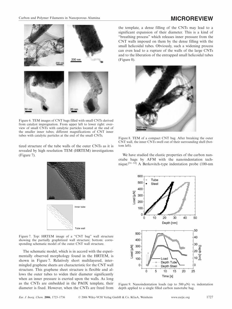
We have studied the elastic properties of the carbon nan-otube bags by AFM with the nanoindentation tech-nique.[31–33] A Berkovitch-type indentation probe (100-nm
Figure 9. Nanoindentation loads (up to 500 µN) vs. indentationdepth applied to a single filled carbon nanotube bag.

J. J. Schneider, J. EngstlerMICROREVIEWtip radius) was placed in the middle of a single carbon nano-tube bag. Experiments were conducted with up to 500-µNloads on the tip (Figure 9, top). Up to loads of 220 µN, theindentation depth increased linearly with increasing load.In the low-load regime (up to ca. 60 µN) the CNT displayedviscoelastic behaviour with nearly no residual plastic defor-mation (�1 nm). When the final indentation load was in-creased to 500 µN, the depth of impression on the carbonnanotube bag structure increased considerably to 35 nm.However, at a load of 230 µN a sudden deviation from alinear behaviour was found (Figure 9, top).
After release of the maximum load a residual depth ofimpression of 27 nm remained in the material (Figure 9,bottom). Compared with the low-load regime, where amaximum load of 60 µN was applied, this dramatically dif-ferent behaviour at higher loads may be attributed to a sud-den rupture of the CNT wall structure. In the low-load re-gime, the filled CNT nanotubes show viscoelastic behaviourtypically observed for soft matter (e.g. polymers), whereashigh enough compression loads lead to the destruction ofthe outer CNTs (see Figure 8).
CNTs in PAOX Derived from Single-Source PrecursorMolecules
There have been several reports on the synthesis of CNTsusing single-source precursors.[34] Examples for such pre-cursors are organometallic compounds like metallocenes orcoordination compounds like iron()phthalocyanine.[35,36]
In these precursors, there exists a fixed, stoichiometricallydefined metal-to-carbon ratio. Ferrocene is a prominentprecursor for CNT synthesis by CVD techniques.
Figure 10 displays a typical TEM image of CNTs derivedfrom ferrocene as the sole CNT precursor. In these experi-ments, the CNTs have been first synthesized and then de-posited freely on a freshly cleaved mica surface. Due to thelow carbon-to-iron-catalyst ratio (10:1) when employingferrocene, the CNTs are mostly filled with iron metal.[37]
Figure 10. TEM images of CNTs synthesized via CVD of ferroceneon a native mica support at different magnifications.
When the carbon-to-iron ratio is increased by a factor of7, CNTs with a much lower iron content are formed, andsubsequently no formation of compact iron rods is observedinside the CNTs. Instead, particles are formed in the CNTs(Figure 11). An increase in the carbon-to-iron ratio was
www.eurjic.org © 2006 Wiley-VCH Verlag GmbH & Co. KGaA, Weinheim Eur. J. Inorg. Chem. 2006, 1723–17361728
achieved by adding an additional carbon source to the fer-rocene precursor.[38] We used the polycondensed aromatichydrocarbon decacyclene C36H18 as the additional carbonsource.[26,39,40]
Figure 11. TEM micrograph of a CNT bundle synthesized by depo-sition of a mixture of decacyclene/ferrocene (70:1 at.-%) in PAOX(template removed).
Bundle-like arrangements of CNTs are found after dis-solution of the PAOX template. Metal particles are distrib-uted within these CNT bundles.
When using chromocene, [(η5-C5H5)2Cr], a precursorwith the same carbon-to-metal ratio as that in ferrocene,CNTs are formed under similar conditions (Figure 12).However, in contrast to the CNT material obtained fromthe ferrocene precursor, no metallic wires are formed withinthe tubes. The CNTs contain particles distributed alongsidethe CNTs, although the carbon-to-metal ratio is identicalto that in ferrocene. Obviously, not only the stoichiometriccarbon-to-metal ratio, but also the nature of the catalyticmetal or the precursor are important for the filling of theCNTs, either with metallic rods or particles.
Figure 12. TEM micrographs of template-freed CNTs synthesizedby deposition of chromocene in PAOX. A characteristic parallel-block arrangement of CNTs derived from PAOX is maintained(template removed).
Comparison of the results for CNT synthesis performedby the single-source strategy without a structure-directingtemplate and those for the template-steered synthesis byusing PAOX shows that the resulting CNT materials havedifferent morphologies. CNTs prepared by the templatetechnique display a parallel alignment of CNTs, with over-all straight tube body morphology and defined tube radii.In contrast, CNTs prepared by a template-free CVD pro-cess by using a single-source strategy have a poorer straight-ness, a significant deviation in tube diameter and a randomdistribution of their metal filling.

Carbon and Polymer Filaments in Nanoporous Alumina MICROREVIEWElement-filtered TEM (EFTEM) has provided detailed
information about the elemental distribution of CNT mate-rials. In general, EFTEM enables the recording of two-di-mensional distributions of chemical elements (Li to U) witha resolution down to about 1 nm. Chemical and structuralheterogeneities may thus be imaged by recording elementaldistributions. Applying this technique supplies an enor-mous amount of information relative to conventionalbright-field TEM. In Figure 13, the results of such an EF-TEM investigation of a single CNT synthesized by CVD byusing chromocene as precursor and PAOX as template areshown.
Figure 13. EFTEM investigations on a single CNT (precursor:chromocene): (a) bright-field image of a single CNT with incorpo-rated particles; images of single-element distributions with elementsdisplayed in lower contrast, (b) carbon, (c) oxygen, (d) chromium,(e) aluminium; (scalebar for all images: 100 nm).
The selective elemental mapping gives the spatial distri-bution along the CNT (Figure 13b–e). Obviously, chro-mium is a main constituent. Besides the elements chromiumand carbon, oxygen is also present in the irregularly shapedparticles, which have a diameter between 20 and 30 nm(shown in Figure 13c). Thus, the formation of chromiumoxide particles seems reasonable. The formation of theseoxide particles is yet unclear since the CVD process pro-ceeds under otherwise inert conditions.
The origin of the detected alumina particles (Fig-ure 13c,e: O and Al elemental maps) can be attributed tothe incomplete dissolution process of the PAOX template
Eur. J. Inorg. Chem. 2006, 1723–1736 © 2006 Wiley-VCH Verlag GmbH & Co. KGaA, Weinheim www.eurjic.org 1729
during sample preparation, leaving minor amounts of resid-ual alumina in the sample.
Similar experimental and EFTEM analytical results wereobtained for the synthesis of CNTs by using metallocenesof Ni and Co as single-source precursors. In both cases,CNTs with diameters corresponding to the PAOX templatewere found. The CNTs again contained metal particles in-side the tubes. Ultrathin samples of these CNTs, still em-bedded in the PAOX template, were studied by TEM (Fig-ure 14).
Figure 14. TEM image of an ultrathin sample of CNTs embeddedin PAOX, obtained by microtoming (CVD precursor nickelocene).Dense regions which appear with a dark contrast display the PAOXtemplate walls. Alongside the PAOX tube walls, small nickel par-ticles are deposited. Some appear to be partly embedded in anamorphous carbon shell.
Particles with a high nickel content, which are foundalongside the pore walls of the CNTs and/or the PAOXtemplate, can be detected by EFTEM analysis of such sam-ples. As for the chromocene case, oxygen is present, how-ever its origin cannot be unambiguously determined, nowbecause of the close proximity of the Ni particles to thesurrounding alumina pore walls.
Field Emission from CNT Arrays
An interesting electrical property of CNTs is their field-emission (FE) behaviour. Because of their small diameter,the electronic working function of CNTs is dramatically re-duced. Thus, a tunnelling effect of electrons can occur, andconsequently theoretical and experimental studies on theelectron emission of CNTs have been in the focus of re-search already for more than one decade.[39,41] MultiwalledCNTs (MWCNTs) are mechanically more robust and arealso less prone to electrical degradation than single-walledCNTs (SWCNTs). The emission from MWCNTs showsmetal-like behaviour, as deduced from electron spectro-scopic studies.[42] For MWCNTs, characteristic parametersin FE, such as the onset field for emission, current densityand electrical field enhancement factors β,[43] are drasticallyimproved[44,45] relative to other relevant FE materials likediamond tips,[46] Si[47] and GaN,[48] which were studied in-tensively over the past years.
For isolated, single CNTs, ten times higher field enhanc-ing factors β are observed relative to CNT films containingbundles of unordered tubes.[49] Thus, different strategies canbe followed to obtain good field-emitting devices based onSWCNTs or MWCNTs. One general strategy seeks the mostperfect two-dimensional arrangement of CNTs in order to

J. J. Schneider, J. EngstlerMICROREVIEWarrange as many emitters as possible on a substrate.[50] Thisassures that a huge number of high aspect ratio structuresare produced and are available for FE. Another syntheticstrategy arranges CNT emitters in defined areas with a highenough distance to each other, thus fulfilling the theoreticalrequirement that the distance between single emitters isabout the height of an individual emitter to obtain long-term FE stability.[51] By realizing the latter approach, theinter-emitter field penetration due to charging and electricaldegradation is significantly reduced relative to arrange-ments where a higher emitter density is achieved (Fig-ure 15).
Figure 15. Schematics showing the dependence of the individualelectrical field penetration of CNT emitters as a function of theemitter distance. Idealized model (top), model of a realistic CNTsurface with high emitter surface coverage (bottom).
Densely populated CNT cathodes therefore have definitedisadvantages in their FE behaviour at low fields due tomutual shielding effects (Figure 15).[51] Well-separatedCNTs with still high enough densities per area and homo-geneous FE characteristics, however, need synthesis tech-niques other than the former.[44] Up to this date, successfulstudies have been reported to optimize the FE performancefor aligned CNTs.[41e,45,50,52–54] We used PAOX as a templat-ing material for CNTs and investigated the resulting FEproperties.[55] In these experiments, additional positive in-
Figure 16. Typical SEM image of isolated CNTs grown on the surface of the PAOX membrane by CVD for FE investigations. The CNTsresponsible for FE are linked to the surface of the PAOX by CVD deposition on predeposited alumina islands; right: emission pictureof such a sample (size 28 mm2) after conditioning (see text).[59]
www.eurjic.org © 2006 Wiley-VCH Verlag GmbH & Co. KGaA, Weinheim Eur. J. Inorg. Chem. 2006, 1723–17361730
fluences of PAOX on the FE behaviour could be detected:for example, electrical insulation of the CNT emitters dueto their embedding in the dielectric matrix of PAOX seemsadvantageous in avoiding destructive degradation by fieldeffects.[51] On the other hand, it has been observed that anoutgrow of CNTs over the PAOX surface promotes FEproperties.[56] For CNTs which are overgrowing the PAOXtemplate structure, low onset fields for emission of 3–4 V µm–1 are found. In contrast to these results, CNTswhich are totally embedded in PAOX and do not surmountthe surface at all, have ten times higher onset fields forFE.[55]
Our work in the area of synthesis and arrangement ofCNTs for FE applications has so far focussed on metallo-cenes or mixtures of metallocenes with polycondensed aro-matics as precursors for CNT synthesis.[29,44,57–59] Growingof CNTs by using metallocene precursors was achieved inand on the surface of PAOX membranes and led to an un-ordered growth on the PAOX surface. Good FE character-istics for such materials were observed when alumina par-ticles were first deposited by CVD from a precursor [source:aluminium tris(sec-butoxide)] on the PAOX surface prior toCNT deposition by CVD (precursor: ferrocene). Then,CNT growth preferentially occurred on the deposited alu-mina islands (Figure 16).[44,58–60]
FE measurements on this material where performed in adiode configuration. The emission picture was obtained af-ter sample conditioning by current processing.[58,59] Sampleconditioning is a standard procedure in FE studies and isnecessary because the FE effect and especially the long-term stability of the emitters are very sensitive to any sur-face and gaseous atmospheric impurity.[58–60] Integral FEmeasurements on such samples have yielded current densi-ties up to 32 mA cm–2 at 7.2 V µm–1.[59] These values arebased on a uniform emitter distribution and an emitternumber density of 10000 cm–2. This is so far a superior re-sult compared with current values from other studies.[52–54]
Single-emitter investigations on the material revealedstable Fowler-Nordheim-like I–V curves.[58] Despite the ob-servation of some short-term current fluctuations, the alu-mina-based CNT cathodes provide already reasonable long-term current stability (�18 h) as shown in Figure 17 andFigure 18.

Carbon and Polymer Filaments in Nanoporous Alumina MICROREVIEW
Figure 17. Long-term current stability of a 28-mm2 sample onPAOX at various pressures/fields: 2×10⁻⁶ mbar at 4.6 V µm–1 (up-per trace); 5×10⁻⁵ mbar at 5.3 V µm–1 (middle trace); 5×10⁻⁴ mbarat 6.5 V µm–1 (lower trace).[59]
Figure 18. Comparison of the typical long-term current stability ofa CNT cathode measured at 10–6 mbar at 4.6 V µm–1 before (uppertrace) and after processing (lower trace) up to 700 µA.[59]
Nevertheless, developing stable CNT field emitters withhigh performance characteristics is an important task inthis research area (long-term stability � 10000 h). Further-more, an aligned and directed growth of CNTs has to berealized in order to obtain well-separated nanotubes. Suchan alignment of emitter structures is so far only realized inSpindt type configurations, which are up to now still theonly industrially viable field emitter structures.
3.2 Polymeric Structures in and on PAOX
Synthesis and Alignment of Polymeric Poly(p-xylene)(PPX) Filaments Derived from PAOX
The first reports on the synthesis of polymer tubes andcylinders in PAOX templates appeared in the mid1990s.[61–63] A recently explored technique uses the con-trolled wetting of ordered pores of PAOX to generate poly-mer nanotubes.[64,65] In this approach, the high-energy sur-face of a PAOX membrane is wetted by a low-energy or-ganic polymer to fill the pores and mould the PAOX tem-plate structure. This results in formation of polymeric nano-tubes after removal of the template. With this technique,
Eur. J. Inorg. Chem. 2006, 1723–1736 © 2006 Wiley-VCH Verlag GmbH & Co. KGaA, Weinheim www.eurjic.org 1731
2D arranged polystyrene, polytetrafluoroethylene (PTFE),polymethyl methacrylate (PMMA) or palladium/polymercomposite materials are accessible in filamentous form,either embedded in the template or freed from the tem-plate.[64,65] 2D confinement studies of symmetric and asym-metric block copolymers in PAOX templates have been re-ported recently.[66,67] Formation of polymer or block copol-ymer nanorods is driven by capillary forces which force thepolymer[66] or copolymer melt[67] into the cylindrical nano-pores of the PAOX template. These studies show that micro-phase separated copolymers are formed within the nano-channels of PAOX. The observed polymer structures arenot only triggered by the pore size of the template but alsoby the specific interaction of pore wall with polymer, lead-ing to phase-segregated copolymer rods in which for exam-ple styrene or polybutadiene forms the central core.[67,68]
Gas phase processes have been studied recently to formtube- or wire-like structures of other technically importantpolymers, like poly(p-xylene), PPX, in PAOX.[68] PPX filmshave very good electrical insulation and barrier properties,excellent solvent and hydrolytic resistance, biocompatibility,transparency and thermomechanical properties. PPX isformed by evaporation and vapour-phase pyrolysis of [2.2]-paracyclophanes as precursors. 1,4-Quinodimethanes areformed as intermediates, acting as monomers (Scheme 1).The in situ formed quinodimethanes polymerize spontane-ously on nearly any given substrate upon vapour phase de-position at temperatures equal to or below 30 °C by forma-tion of conformal highly adhesive PPX films.[69]
Scheme 1. Formation of PPX polymer starting from [2.2]paracyclo-phane precursor via intermediate 1,4-quinodimethane.
Within PAOX, PPX can be synthesized in a fibre mor-phology by chemical vapour deposition polymerization.Figure 19 shows a top and side view of a PPX film formedon PAOX after CVD polymerization deposition. PPX formsa closed film on top of the template, covering its surfacecompletely.
PPX fibres are formed within the pores of the template(Figure 19). The compact PPX films on top of the templatecan be detached from the surface mechanically or by chemi-cal techniques.
The ordered backside of PAOX membranes can be usedfor patterning a polymer such as PPX in a straightforwardtechnique by moulding the backside when using it as a mas-ter form. This master backside with desired nanodimen-sions can be prepared by electrochemical oxidation of alu-minium metal and detachment of the film from the metalbase. This simple technique avoids complicated physicalstructuring processes like e-beam lithography for shaping a

J. J. Schneider, J. EngstlerMICROREVIEW
Figure 19. SEM image of a PAOX/PPX composite surface. FibrousPPX structures protude out of the pores of the PAOX template.
master form, which can then be used in the moulding pro-cess. Instead, the self-organization process of forming thenanostructured alumina cells is used to produce the masterform. The barrier layer of PAOX provides a nanostructuredsurface with regular hexagonally ordered concave domes(Figure 20). A replication of the backside PAOX structurewith a polymer film may thus represent a straightforwardway to nanostructured polymer surfaces with an inversemorphology when detached from the master.
Figure 20. AFM image of a closed PAOX backside with hexagonalpore order used as master in moulding experiments with PPX; bot-tom: corresponding height profile.
The coating of the PAOX backside template with a thinPPX film can be done in a CVD reactor consisting of aquartz reactor tube in which a three-zone heating can berealized. A temperature gradient from 170° to 700 °C issuitable for sublimation and for initiating the in situ CVDpolymerization. After CVD polymerization, the PPX filmon the backside of the membrane can either be lifted off
www.eurjic.org © 2006 Wiley-VCH Verlag GmbH & Co. KGaA, Weinheim Eur. J. Inorg. Chem. 2006, 1723–17361732
mechanically or detached chemically from the resultingPPX/PAOX composite to give a structured PPX film. Thisprocess is shown schematically in Figure 21.
Figure 21. Schematic drawing showing the steps involved in themoulding of a PAOX backside to yield a PPX polymer as well asits detachment to obtain a freestanding nanostructured PPX film.
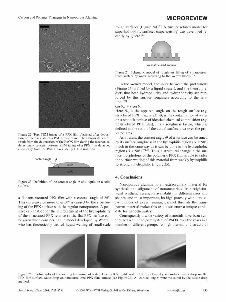
Figure 22 compares the appearance of a structured PPXfilm after mechanical lift-off with that after chemical de-tachment from the PAOX template. The breaking of thefilm by mechanical stress during the detachment results inthe formation of fibrous structures. In contrast, the mor-phology of the structured PPX film can be retained intactover wide areas by chemical detachment from the master.The film then shows a regular concave structure, in whichthe small dimples mirror an almost ideal replication of theconvex dome-like PAOX backside structure.
Such nanostructured surfaces may show a drastically al-tered wetting behaviour. Measuring the contact angle at asolid/liquid/gas interface is a very sensitive surface analyti-cal method. It probes the outer atomic layers of a surfaceand enables the study of chemical as well as morphologicalsurface changes.[70,71]
The hydrophilicity/hydrophobicity of a surface can be de-termined by measuring the contact angle Θ between waterand the surface (Figure 23). A contact angle of 0° relates toa flat monomolecular water film on a surface of a solid. Ata contact angle of 180°, a drop of water, for example, is incontact with the surface only at a single point (superhydro-phobic). Between these extremes, surfaces are termed hy-drophilic (�90°) or hydrophobic (�90°).
The contact angle of water on a flat PPX surface is 86°(weak hydrophilic behaviour). This compares with an angleof 14° for water on a flat glass surface (roughness � 0.5 nm,piranha-solution-cleaned glass), which is classified as super-hydrophilic.[72] The nanostructured PPX film (see Fig-ure 22) which represents a rough surface, shows a drasti-cally reduced water contact angle of only 24° compared to
Carbon and Polymer Filaments in Nanoporous Alumina MICROREVIEW
Figure 22. Top: SEM image of a PPX film obtained after deposi-tion on the backside of a PAOX membrane. The fibrous structuresresult from the destruction of the PAOX film during the mechanicaldetachment process; bottom: SEM image of a PPX film detachedchemically from the PAOX backside by HF dissolution.
Figure 23. Definition of the contact angle Θ of a liquid on a solidsurface.
a flat unstructured PPX film with a contact angle of 86°.This difference of more than 60° is caused by the structur-ing of the PPX surface with the regular nanopattern. A pos-sible explanation for the reinforcement of the hydrophilicityof the structured PPX relative to the flat PPX surface canbe given when considering the model developed by Wenzel,who has theoretically treated liquid wetting of small-scale
Figure 25. Photographs of the wetting behaviour of water. From left to right: water drop on cleaned glass surface, water drop on flatPPX film surface, water drop on nanostructured PPX film surface (see Figure 22). All contact angles were measured by the sessile dropmethod.
Eur. J. Inorg. Chem. 2006, 1723–1736 © 2006 Wiley-VCH Verlag GmbH & Co. KGaA, Weinheim www.eurjic.org 1733
rough surfaces (Figure 24).[73] A further refined model forsuperhydrophilic surfaces (superwetting) was developed re-cently by Quéré.[74]
Figure 24. Schematic model of roughness filling of a nanostruc-tured surface by water according to the Wenzel theory.[73]
In the Wenzel model, the space between the protrusions(Figure 24) is filled by a liquid (water), and the theory pre-dicts that both hydrophilicity and hydrophobicity are rein-forced by this surface roughness according to the rela-tion:[73]
cosΘw = r cosΘt
Here Θw is the apparent angle on the rough surface (e.g.structured PPX, Figure 22), Θt is the contact angle of wateron a smooth surface of identical chemical composition (e.g.unstructured PPX film), r is a roughness factor, which isdefined as the ratio of the actual surface area over the pro-jected area.
As a result, the contact angle Θ of a surface can be tunedby its surface roughness in the hydrophilic region (Θ � 90°)much in the same way as it can be done in the hydrophobicregion (Θ � 90°).[74,75] Thus, a structural change in the sur-face morphology of the polymeric PPX film is able to tailorthe surface wetting of this material from weakly hydrophilicto strongly hydrophilic (Figure 25).
4. Conclusions
Nanoporous alumina is an extraordinary material forsynthesis and alignment of nanomaterials. Its straightfor-ward synthetic access, its availability in different sizes andshapes, and most important, its high porosity with a mass-ive number of pores running parallel through the trans-parent material makes this oxidic structure a unique candi-date for nanochemistry.
Consequently a wide variety of materials have been syn-thesized within the pore system of PAOX over the years in anumber of different groups. Its high thermal and structural

J. J. Schneider, J. EngstlerMICROREVIEWstability makes PAOX also useful as template in gas-phaseCVD processes.
Herein we have described the formation, alignment andFE properties of CNTs inside the pores and on the surfaceof PAOX. Various single-source precursors were studiedand led to the formation of CNTs with and without metalfilling of their interior.
In field emission, we found that PAOX has a significantinfluence on the emission characteristics, which is provenby the highest dc current density so far measured for CNTstructures, for example. Moreover long current stabilities ofup to 18 h were obtained for these materials after cathodeconditioning was employed.
Polymer wires are accessible by a gas-phase route by po-lymerizing reactive polymer precursors inside the pores ofPAOX. Besides the polymerization inside porous alumina,PAOX can be used as a mould to emboss organic polymers.PPX films with a resulting concave surface structure canbe deposited on the dome-shaped backside of PAOX andafterwards securely detached from it. This leads to a nanos-tructured polymer surface, which shows an increased hydro-philicity relative to an unstructured flat PPX polymer film.This may be attributed to an enhanced wetting behaviourof the regular nanopatterned structure relative to a smoothunstructured PPX surface.
The future for even more synthetic as well as technologi-cal applications of porous alumina membranes is worth be-ing explored in more detail. Research areas like catalysis,for which its mesopores can be tailored and chemicallymodified, have been barely touched so far.[76–78] Nanoreac-tors based on PAOX membranes could be an interestingextension of the already well-established microreactor tech-nique.
Biomolecules are ideal candidates for immobilization in-side the pore volume of PAOX because of the variable tem-plate pore size in the mesoporous range. Biosensor actionis a possible target application that can be realized withsuch systems.[79] The sector of medical applications of theseinorganic membranes is also under current study.[80]
Acknowledgments
Our work was supported by the DFG and the Volkswagenstiftung.The authors gratefully acknowledge the fruitful cooperation in col-laborations with FELMI, Graz (EFTEM, Prof. Dr. F. Hofer, TUGraz), with the Erich Schmid Institute of the Austrian Academyof Science, Leoben (Dr. T. Schöberl), both in Austria, and withProf. Dr. G. Müller, Physics Department, Wuppertal University.
[1] a) M. Terrones, R. Kamalukaran, T. Seeger, M. Rühle, Chem.Commun. 2000, 2335–2336; b) E.-G. Wang, Adv. Mater. 1999,11, 1129–1133; c) M. Terrones, P. Redlich, N. Grobert, S. Tra-sobares, W. K. Hsu, H. Terrones, Y. Q. Zhu, J. P. Hare, C. L.Reeves, A. K. Cheetham, M. Rühle, H. W. Kroto, D. R. M.Walton, Adv. Mater. 1999, 11, 655–658; d) N. Grobert, M. Ter-rones, S. Trasobares, K. Kordatos, H. Terrones, J. Olivares, J. P.Zhang, P. Redlicj, W. K. Hsu, C. L. Reeves, D. J. Wallis, Y. Q.Zhu, J. P. Hare, A. J. Pidduck, H. W. Kroto, D. R. M. Walton,Appl. Phys. A 2000, 70, 175–183.
www.eurjic.org © 2006 Wiley-VCH Verlag GmbH & Co. KGaA, Weinheim Eur. J. Inorg. Chem. 2006, 1723–17361734
[2] W. Tremel, Angew. Chem. 1999, 111, 2311–2315; Angew. Chem.Int. Ed. 1999,38, 2175–2179.
[3] a) M. Remskar, Z. Skraba, F. Cleton, R. Sangines, F. Levy,Appl. Phys. Lett. 1996, 69, 351–353; b) C. M. Zelenski, P. K.Porhout, J. Am. Chem. Soc. 1998, 120, 734–742; c) L. Margulis,G. Salitra, R. Tenne, M. Taliankar, Nature 1993, 365, 113–114;d) Y. Feldmann, E. Wassermann, D. J. Srolovitz, R. Tenne, Sci-ence 1995, 267, 222–225.
[4] a) R. L. O. Whitby, W. K. Hsu, C. B. Boothroyd, P. K. Fearon,H. W. Kroto, D. R. M. Walton, ChemPhysChem 2001, 2, 620–623; b) E. B. Macki, D. H. Galvan, E. Adam, S. Talapatra, G.Yang, A. D. Migone, Adv. Mater. 2000, 12, 495–498; c) R.Tenne, L. Margulis, M. Genet, G. Hodes, Nature 1992, 360,444–446.
[5] a) W. Mickelson, S. Aloni, Wei-Qiang Han, J. Cummings, A.Zettl, Science 2003, 300, 467–469; b) E. J. M. Hamilton, S. E.Dalton, C. M. Mann, H. O. Cilija, C. A. McDonald, S. G.Shore, Science 1993, 260, 659–661; c) R. Ma, Y. Bando, T. Sato,K. Kurashima, Chem. Mater. 2001, 13, 2965–2971.
[6] a) R. B. Wehrspohn, J. Schilling, MRS Bull. 2002, 8, 263; b)M. S. Sander, A. L. Prieto, R. Gronsky, T. Sands, A. M. Stacy,Adv. Mater. 2002, 14, 665–667; c) S.-Z. Chu, K. Wada, S. In-oue, M. Isogai, A. Yasumori, Adv. Mater. 2005, 17, 2115–2119;d) P. P. Mardilovich, A. N. Govyadinov, N. I. Mazurenko, R.Paterson, J. Membr. Sci. 1995, 98, 143–155; e) N. Itoh, K.Kato, T. Tsuij, M. Hongo, J. Membr. Sci. 1996, 117, 189–196;f) A. T. Shawaqfeh, R. E. Baltus, J. Membr. Sci. 1999, 157,147–158; g) J. H. Yuan, F. Y. He, D. C. Sun, X. H. Xia, Chem.Mater. 2004, 16, 1841–1844; h) F. Li, L. Zhang, R. Metzger,Chem. Mater. 1998, 10, 2470–2480; i) A. Michailowski, D. Al-Mawlawi, G. Cheng, M. Moskovits, Chem. Phys. Lett. 2001,349, 1–5; j) Y. Wang, J. Y. Lee, H. C. Zjeng, Chem. Mater. 2005,17, 3899–3903; k) K. B. Shelimov, M. Moskovits, Chem. Mater.2000, 12, 250–254; l) F. Li, J. He, W. L. Zhou, J. B. Wiley, J.Am. Chem. Soc. 2003, 125, 16166–16167; m) B. A. Hernandez,K. S. Chang, E. R. Fisher, P. K. Dorhout, Chem. Mater. 2002,14, 480–482; n) C. Y. Kuo, S. Y. Lu, T.-Y. Wei, J. Cryst. Growth2005, 285, 400–407.
[7] G. Schmid, J. Mater. Chem. 2002, 12, 1231–1238.[8] T. L. Wade, J.-E. Wegrove, Eur. Phys. J. Appl. Phys. 2005, 29,
3–22.[9] F. Keller, M. S. Hunter, D. L. Robinson, J. Electrochem. Soc.
1953, 100, 411–419.[10] G. C. Wood, J. P. O’Sullivan, Proc. R. Soc. 1970, A317, 511–
543.[11] K. Nielsch, J. Choi, K. Schwirn, R. B. Wehrspohn, U. Gösele,
Nano Lett. 2002, 2, 677–680.[12] a) S. Ono, N. Masuko, Corros. Sci. 1992, 33, 503–505; b) S.
Ono, H. Ichinose, N. Masuko, Corros. Sci. 1992, 33, 841–850.[13] V. P. Parkhuitik, V. I. Shershulsky, J. Phys. 1992, D25, 1258–
1263.[14] S. Z. Chu, K. Wada, S. Inoue, S.-I. Todoroki, Chem. Mater.
2002, 14, 4595–4602.[15] M. Tian, S. Xu, J. Wang, N. Kumar, E. Wertz, Q. Li, P. M.
Campbell, M. H. W. Chan, T. E. Mallouk, Nano Lett. 2005, 5,697–703.
[16] H. de L. Lira, R. Paterson, J. Membr. Sci. 2002, 206, 375–387.[17] L. J. Gibson, M. F. Ashby, Cellular Solids: Structure and Prop-
erties, Pergamon Press,1988.[18] a) M. Wada, Y. Kitano, S. Tanase, O. Kajita, T. Sakai, J. Elec-
trochem. Soc. 2005, 152, A1341–A1346; b) P. T. Kumar, R. Ra-mesh, Y. Y. Lin, G. T. K. Fey, Electrochem. Commun. 2004, 6,520–525.
[19] M. Valcarcel, B. M. Simonet, S. Cardenas, B. Suarez, Anal. Bi-oanal. Chem. 2005, 382, 1783–1790.
[20] a) F. Pico, J. M. Rojo, M. L. Sanjuan, A. Anson, A. M. Benito,M. A. Callejas, W. K. Maser, M. T. Martinez, J. Electrochem.Soc. 2004, 151, A831–837; b) J. H. Chen, W. Z. Li, D. Z. Wang,S. X. Yang, J. G. Wen, Z. F. Ren, Carbon 2002, 40, 1193–1197;

Carbon and Polymer Filaments in Nanoporous Alumina MICROREVIEWc) G. Seifert, T. Kohler, T. Frauenheim, Appl. Phys. Lett. 2000,77, 1313–1315.
[21] a) S. H. Jeong, H. Y. Hwang, K. H. Lee, Y. Jeong, Appl. Phys.Lett. 2001, 78, 2052–2054; b) Y. Zhang, J. Liu, X. Li, Proc.XIV IVMC 2001, 13.
[22] a) C. Kocabas, S. H. Hur, A. Gaur, M. A. Meitl, M. Shim, J. A.Rogers, Small 2005, 1, 1110–1116; b) Z. B. Zhang, J. Cardenas,E. E. B. Campbell, S. L. Zhang, Appl. Phys. Lett. 2005, 87,043110/1–043110/3; c) T. Shimada, T. Sugai, Y. Ohno, S. Kishi-moto, T. Mizutani, H. Yoshida, T. Okazaki, H. Shinohara,Appl. Phys. Lett. 2004, 84, 2412–2414.
[23] T. Kyotani, .-F. Tsai, A. Tomita, Chem. Mater. 1996, 8, 2109–2113.
[24] T. Yanagishita, M. Sasaki, K. Nishio, H. Masuda, Adv. Mater.2004, 16, 429–432.
[25] N. I. Maksimova, J. Engstler, J. J. Schneider, Nato ASCI Series2006, in press.
[26] J. J. Schneider, N. I. Maksimova, J. Engstler, R. Schierholz,New. J. Chem. 2006, submitted.
[27] P. C. P. Watts, W. K. Hsu, D. P. Randell, V. Kotzeva, G. Z.Chen, Chem. Mater. 2002, 14, 4505–4508.
[28] H. Hou, A. K. Schaper, F. Weller, A. Greiner, Chem. Mater.2002, 14, 3994–3999.
[29] J. J. Schneider, J. Engstler, S. Franzka, K. Hofmann, B. Albert,J. Ensling, P. Gütlich, P. Hildebrandt, S. Döpner, W. Pfleging,B. Günther, G. Müller, Chem. Eur. J. 2001, 7, 2888–2895.
[30] G. Che, B. B. Lakshmi, E. R. Fisher, C. R. Martin, Nature1998, 393, 346–349.
[31] W. Guo, C. Z. Zhu, T. X. Yu, H. Woo, B. Hang, Y. T. Dai,Phys. Rev. Lett. 2004, 93, 245502/1–245502/4.
[32] H. J. Qi, K. B. K. Teo, K. K. S. Lau, M. C. Boyce, W. I. Milne,J. Robertson, K. K. Gleason, J. Mech. Phys. Solids 2003, 51,2213–2237.
[33] Y. R. Jeng, P. C. Tsai, T. H. Fang, J. Chem. Phys. 2005, 122,224713/1–224713/8.
[34] C. N. R. Rao, A. Govindaraj, Acc. Chem. Res. 2002, 35, 998–1007 and references cited therein.
[35] J. Wu, B. E. Hamaoui, J. Li, L. Zhi, U. Kolb, K. Müllen, Small2005, 1, 210–212.
[36] L. Zhi, T. Gorelik, R. Friedlein, J. Wu, U. Kolb, W. R. Sal-aneck, K. Müllen, Small 2005, 1, 798–801.
[37] See also: a) C. N. R. Rao, B. Satishkumar, A. Govindarai, M.Nath, ChemPhysChem 2001, 2, 78–105; b) C. N. R. Rao, R.Sen, B. C. Satishkumar, A. Govindarai, Chem. Commun. 1998,1525; c) C. N. R. Rao, A. Govindaraj, Acc. Chem. Res. 2002,35, 998–1007.
[38] a) A. R. Harutyunyan, G. Chen, P. C. Eklund, Appl. Phys. Lett.2003, 82, 4794–4796.
[39] A. R. Harutyunyan, G. Chen, P. C. Eklund, Appl. Phys. Lett.2003, 82, 4794–4796.
[40] Y. Saito, S. Uemura, Carbon 2000, 38, 169–182.[41] a) P. M. Ajayan, O. Stephan, C. Colliex, D. Trauth, Science
1994, 265; 1212–1214; b) J. I. Sohn, S. Lee, Mat. Res. Soc.,Symp. Proc. 2001, 63A, 14.9.1–14.9.6; c) Y.-H. Lee, Y.-T. Jang,D.-H. Kim, J.-H. Ahn, B. K. Ju, Adv. Mater. 2001, 13, 479–482; d) X. Xu, G. R. Brandes, Mat. Res., Symp. Proc. 1998,509, 107; e) L. A. de Heer, D. Ugarte, A. Chatelain, Science1995, 270, 1179–1180.
[42] a) M. J. Fransen, T. L. van Rooy, P. Kruit, Appl. Surf. Sci.1999, 146, 312–327; b) J. W. Gadzuk, E. W. Plummer, Rev.Mod. Phys. 1973, 45, 487.
[43] β is the electrical field enhancement factor of an external elec-trical field applied to an emitting structure. It is greatly influ-enced (aside from other factors) by a high aspect ratio of theemitting structure. β is a measure of the lowering of the onsetfield of FE which is typically between E = 1–10 V µm–1 forCNTs. β for MWCNTs can be determined from a Fowler-Nordheim plot assuming a work function of 4.6 eV for graph-ite.
Eur. J. Inorg. Chem. 2006, 1723–1736 © 2006 Wiley-VCH Verlag GmbH & Co. KGaA, Weinheim www.eurjic.org 1735
[44] B. Günther, A. Göhl, G. Müller, J. Engstler, J. J. Schneider,Proc. 13th IVMC 2001, 207, 2000.
[45] M. Stammler, J. Ristein, T. Habermann, A. Göhl, K. Janos-chowsky, D. Nau, G. Müller, L. Ley, Diam. Relat. Mater. 1999,8, 792–792.
[46] a) T. Habermann, A. Göhl, D. Nau, M. Wedel, G. Müller, M.Christ, M. Schreck, B. Stritzker, J. Vac. Sci. Technol. 1998, B16,693–696; b) A. Göhl, T. Habermann, G. Müller, D. Nau, M.Wedel, G. Müller, M. Christ, M. Schreck, B. Stritzker, Diam.Relat. Mater. 1998, 7, 666–670.
[47] a) F. M. Charbonnier, W. A. Mackie, T. Xie, P. R. Davis, Ultra-microscopy 1999, 79, 73–82; b) S. Kanemaru, T. Hirano, H.Tanoue, J. Itoh, J. Vac. Sci. Techn. 1996, B14, 1885–1888; c)M. S. Chung, B.-G. Yoon, J. M. Park, K.-Y. Ha, Appl. Surf.Sci. 1999, 146, 138–142.
[48] a) N. N. Chubun, A. G. Chakhovskoi, M. Hajra, C. E. Hunt,J. Vac. Sci. Technol. B 2003, 21, 483–485; b) M. Hajra, N. N.Chubun, A. G. Chakhovskoi, C. E. Hunt, K. Liu, A. Murali,S. H. Risbud, T. Tyler, V. Zhirnov, J. Vac. Sci. Technol. B 2003,21, 458–463; c) B. R. Chalamala, R. H. Reuss, K. A. Dean,Appl. Phys. Lett. 2001, 78, 2375–2377.
[49] J. M. Kim, W. B. Choi, N. S. Lee, J. E. Jung, Diam. Relat. Ma-ter. 2000, 9, 1184–1189.
[50] O. Gröning, O. M. Küttel, C. Emmenger, P. Gröning, L.Schlappbach, J. Vac. Sci. Technol. 2000, B18, 665–678.
[51] L. Nilsson, O. Groenning, C. Emmengger, O. Kuettel, E.Schaller, L. Schlappach, H. Kind, J.-M. Bonard, K. Kern,Appl. Phys. Lett. 2000, 76, 2071–2073.
[52] J. L. Kwo, M. Yokoyama, W. C. Wang, F. Y. Chuang, I. N. Lin,Diam. Relat. Mater. 2000, 9, 1270–1274.
[53] S. Kanemaru, T. Hirano, H. Tanoue, J. Itoh, Appl. Surf. Sci.1997, 111, 218–223.
[54] J. I. Sohn, S. Lee, Y.-H. Song, S.-Y. Choi, K.-I. Cho, K. S.Nam, Curr. Appl. Phys. 2001, 1, 61–65.
[55] D. N. Davydov, P. A. Sattari, D. AlMawlawi, A. Osika, T. L.Daslett, M. Moskovits, J. Appl. Phys. 1999, 86, 3983–3987.
[56] a) J. S. Suh, K. S. Jeong, J. S. Lee, I. Han, Appl. Phys. Lett.2002, 80, 2392–2394; b) S. H. Jeong, H. Y. Hwang, K. H. Lee,Y. Jeong, Appl. Phys. Lett. 2001, 78, 2052–2054; c) Z. H. Yuan,H. Huang, Y. Dang, J. E. Cao, B. H. Hu, S. S. Fan, Appl. Phys.Lett. 2001, 78, 3127–3129.
[57] F. Kaldasch, B. Günther, G. Müller, J. Engstler, J. J. Schneider,Proc. IVMC 2001, 01TH8586, 25.
[58] J. Engstler, dissertation University Duisburg-Essen, Essen,2003.
[59] D. Lysenkov, H. Abbas, G. Müller, J. Engstler, K. P. Budna,J. J. Schneider, J. Vac. Sci. Technol. B 2005, 23, 809–813.
[60] B. Günther, dissertation, University Wuppertal, WUBDiss.02-8, 2002.
[61] H. Masuda, K. Nishio, N. Baba, Jpn. J. Appl. Phys. 1992, 31,1775–1777.
[62] H. Masuda, K. Fukuda, Science 1995, 268, 1466–1468.[63] C. Goh, K. M. Coakley, M. D. McGehee, Nano Lett. 2005, 5,
1545–1549.[64] M. Steinhart, J. H. Wendorff, A. Greiner, R. B. Wehrspon, K.
Nielsch, J. Schilling, J. Choi, U. Gösele, Science 2002, 296,1997.
[65] A. H. Greiner, J. H. Wendorf, M. Steinhart, Nachr. Chem.2004, 52, 426–431.
[66] S. I. Moon, T. J. McCarthy, Macromolecules 2003, 36, 4253–4255.
[67] H. Xiang, K. Shin, T. Kim, S. I. Moon, T. J. McCarthy, T. P.Rusell, Macromolecules 2004, 37, 5660–5664.
[68] Ph. Hanefeld, O. Kriha, J. Engstler, M. Steinhart, U. Gösele,J. H. Wendorff, A. Greiner, J. J. Schneider, Chem. Mater. 2006,in press.
[69] W. F. Gorham, J. Polym. Sci. Part A-1 1966, 4, 3027–3039.[70] J. Böing, Diss., RWTH Aachen, 2003.

J. J. Schneider, J. EngstlerMICROREVIEW[71] E. Martines, K. Seunarine, H. Morgan, N. Gadegaard,
C. D. W. Wilkinson, M. O. Riehle, Nano Lett. 2005, 5, 2097–2103.
[72] D. Klee, J. Böing, H. Höcker, Mater.-wiss. u. Werkstofftech.2004, 35, 186–191.
[73] R. N. Wenzel, Ind. Eng. Chem. 1936, 28, 988–994.[74] D. Quéré, Phys. A 2002, 313, 32–46.[75] S. Shibuichi, T. Onda, N. Satoh, K. Tsujii, J. Phys. Chem. 1996,
100, 19512–19517.[76] H.-P. Kormann, G. Schmid, K. Pelzer, K. Philippot, B. Chaud-
ret, Z. Anorg. Allg. Chem. 2004, 630, 1913–1918.[77] a) D. Höneke, Appl. Catal. 1983, 5, 179–198; b) D. Höneke, J.
Catal. 1987, 105, 10–18.[78] D. Höneke, G. Wießmeier, Ind. Eng. Chem. Res. 1996, 35,
4412–4416.[79] a) S. Hou, J. Wang, C. R. Martin, J. Am. Chem. Soc. 2005, 127,
8586–8587; b) P. Kunit, C. R. Martin, Curr. Pharm. Biotechnol.2005, 6, 35–467; c) F. Matsumoto, K. Nishio, H. Masuda, Adv.Mater. 2004, 16, 2105–2108; d) F. Matsumoto, M. Kamiyama,
www.eurjic.org © 2006 Wiley-VCH Verlag GmbH & Co. KGaA, Weinheim Eur. J. Inorg. Chem. 2006, 1723–17361736
N. Kazuyuki, H. Masuda, Jpn. J. Appl. Phys. Part 2 2005, 44,L355–L358; e) M. Herrmann, Chem. Mater. 2005, 17, 4577–4593; f) V. Benoit, A. Steel, M. Torres, Y.-Y. Yu, H. Yang, J.Cooper, Anal. Chem. 2001, 73, 2412–2420; g) B. J. Cheek, A. B.Steel, M. P. Torres, Y.-Y. Yu, H. Yang, Anal. Chem. 2001, 73,5777–578.
[80] a) Patents: DE 1985542i, C2, 2001; DE 199910188, 4–45, 2001;DE 19948783 C2, 2001; b) E. P. Briggs, M. Karlsson, A. R.Walpole, E. Palsgard, P. R. Wilshaw, J. Mater. Sci. Mater. Med.2004, 15, 1–9; c) M. Karlsoon, E. Palsgard, P. R. Wilshaw, L.Di Silvio, Biomaterials 2003, 24, 3039–3046; d) M. Karlsson,A. Johansson, L. Tang, M. Boman, Microsc. Res. Technol.2004, 63, 259–265; e) R. van Beuningen, H. van Damme, P. Bo-eneder, N. Bastiaensen, A. Chan, T. Kievits, Clin. Chem. 2001,47, 1931–1933; f) F. Matsumoto, K. Nishio, H. Masuda, Adv.Mater. 2004, 16, 2105–2107.
Received: December 23, 2005Published Online: April 3, 2006