Capacity Planning - Pmacct
107
© 2010 Cisco Systems, Inc./Cariden Technologies, Inc.. 1 Best Practices in Network Planning and Traffic Engineering RIPE 61, Rome Clarence Filsfils – Cisco Systems Thomas Telkamp – Cariden Technologies Paolo Lucente – pmacct
Transcript of Capacity Planning - Pmacct

© 2010 Cisco Systems, Inc./Cariden Technologies, Inc.. 1
Best Practices in Network Planning and Traffic Engineering
RIPE 61, Rome
Clarence Filsfils – Cisco Systems
Thomas Telkamp – Cariden Technologies
Paolo Lucente – pmacct

2© 2010 Cisco Systems, Inc./Cariden Technologies, Inc..
Outline
• Objective / Intro [CF: 10 min.]
• Traffic Matrix [CF/PL: 20 min., incl. pmacct]
pmacct
• Network Planning [TT: 10 min.]
• Optimization/Traffic Engineering [TT: 25 min.]
• Planning for LFA FRR [CF: 15 min.]
• IP/Optical Integration [CF: 10 min.]
• A final example (+LFA +Optical) [CF: 10 min.]
• Conclusion & References

© 2010 Cisco Systems, Inc./Cariden Technologies, Inc.. 3
Introduction & Objective
4© 2010 Cisco Systems, Inc./Cariden Technologies, Inc..
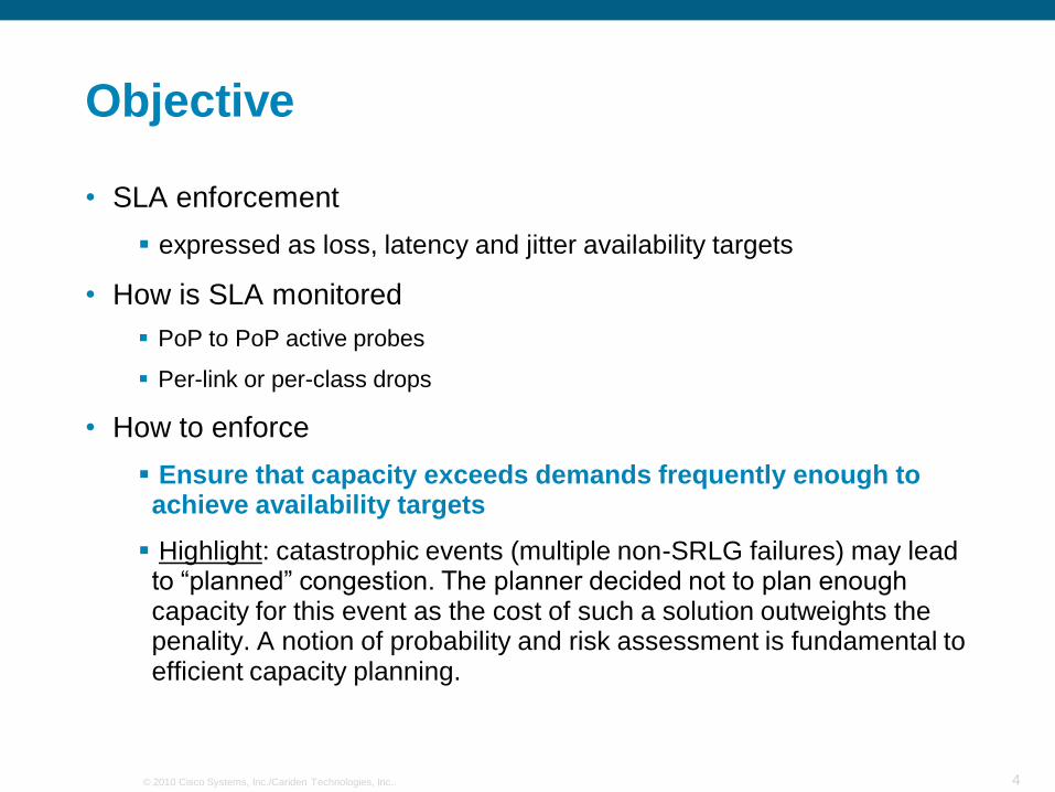
Objective
• SLA enforcement
expressed as loss, latency and jitter availability targets
• How is SLA monitored
PoP to PoP active probes
Per-link or per-class drops
• How to enforce
Ensure that capacity exceeds demands frequently enough to achieve availability targets
Highlight: catastrophic events (multiple non-SRLG failures) may lead to “planned” congestion. The planner decided not to plan enough capacity for this event as the cost of such a solution outweights the penality. A notion of probability and risk assessment is fundamental to efficient capacity planning.

5© 2010 Cisco Systems, Inc./Cariden Technologies, Inc..
Basic Capacity Planning
• Input
Topology
Routing Policy
QoS policy per link
Per-Class Traffic Matrix
• Output
Is Per-class Per-link OPF < a target threshold (e.g. 85%)?
OPF: over-provisioning factor = load/capacity
• If yes then be happy else either modify inputs
or the target output threshold or accept the violation
6© 2010 Cisco Systems, Inc./Cariden Technologies, Inc..
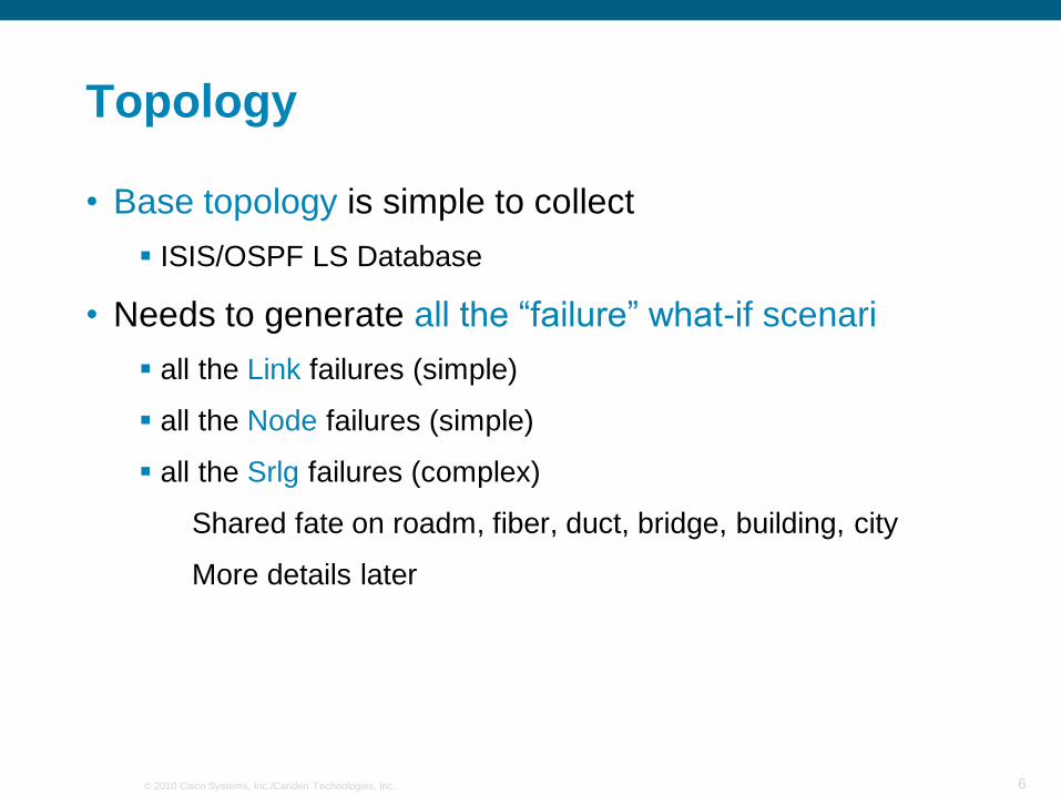
Topology
• Base topology is simple to collect
ISIS/OSPF LS Database
• Needs to generate all the “failure” what-if scenari
all the Link failures (simple)
all the Node failures (simple)
all the Srlg failures (complex)
Shared fate on roadm, fiber, duct, bridge, building, city
More details later
7© 2010 Cisco Systems, Inc./Cariden Technologies, Inc..
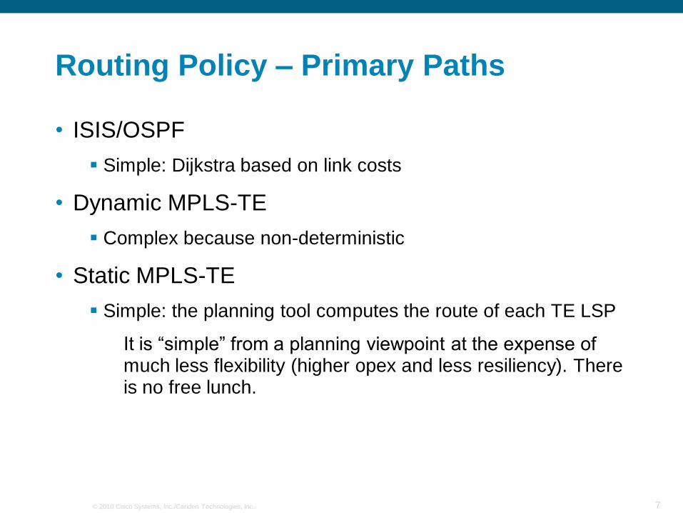
Routing Policy – Primary Paths
• ISIS/OSPF
Simple: Dijkstra based on link costs
• Dynamic MPLS-TE
Complex because non-deterministic
• Static MPLS-TE
Simple: the planning tool computes the route of each TE LSP
It is “simple” from a planning viewpoint at the expense of much less flexibility (higher opex and less resiliency). There is no free lunch.

8© 2010 Cisco Systems, Inc./Cariden Technologies, Inc..
Routing Policy – Backup Paths
• ISIS/OSPF – Routing Convergence
Simple: Dijkstra based on link costs
• ISIS/OSPF - LFA FRR
Complex: the availability of a backup depends on the topology and the prefix, some level of non-determinism may exist when LFA tie-break does not select a unique solution
• Dynamic MPLS-TE – Routing Convergence
Complex because non-deterministic
• Dynamic MPLS-TE – MPLS TE FRR via a dynamic backup tunnel
Complex because the backup LSP route may not be deterministic
• Dynamic MPLS-TE – MPLS TE FRR via a static backup tunnel
Moderate: the planning tool computes the backup LSP route but which primary LSP‟s are on the primary interface may be non-deterministic
• Static MPLS-TE – MPLS TE FRR via static backup tunnel
Simple: the planning tool computes the route of each TE LSP (primary and backup) (reminder… there is a trade-off to this simplicity.

9© 2010 Cisco Systems, Inc./Cariden Technologies, Inc..
QoS policy per-link
• Very simple because
the BW allocation policy is the same on all links
it very rarely changes
it very rarely is customized on a per link basis for tactical goal

10© 2010 Cisco Systems, Inc./Cariden Technologies, Inc..
Over-Provision Factor
• Area of research
• Common agreement that [80-90%] should be ok when underlying capacity is >10Gbps
with some implicit assumptions on traffic being a large mix of independent flows

11© 2010 Cisco Systems, Inc./Cariden Technologies, Inc..
Over-Provision Factor – Research
• Bandwidth Estimation for Best-Effort Internet Traffic
Jin Cao, William S. Cleveland, and Don X. Sun
[Cao 2004]
• Data:
BELL, AIX, MFN, NZIX
• Best-Effort Delay Formula:
• Similar queueing simulation results[Telkamp 2003/2009]:

12© 2010 Cisco Systems, Inc./Cariden Technologies, Inc..
Digression – Why QoS helps
• Link = 10Gbps, Load 1 is 2Gbps, Load 2 is 6Gbps
• Class1 gets 90%, Class2 gets 10%, work-conservative scheduler
• Over-Provisioning Factor (Class1) = 2/9 = 22% <<<< 85% (no risk!)
• OPF (Class2) = 6/8 = 75% and actually even worse if Class1 gets more loaded then expected. Much closer to the 85% target and hence much more risky!
• But fine because the availability target for Class2 is much looser than Class1 (eg. 99% vs 99.999%)
• QoS allows to create excellent OPF for the Tightest-SLA classes at the expense of the loosed-SLA classes.
• More details in [Filsfils and Evans 2005] and in [Deploy QoS]

© 2010 Cisco Systems, Inc./Cariden Technologies, Inc.. 13
Traffic Matrix

14© 2010 Cisco Systems, Inc./Cariden Technologies, Inc..
Traffic Demand Matrix
• Traffic demands define the amount of data transmitted between each pair of network nodes
Typically per Class
Typically peak traffic or a very high percentile
Measured, estimatedor deduced
•1
4

15© 2010 Cisco Systems, Inc./Cariden Technologies, Inc..
Internal Traffic Matrix
• POP to POP, AR-to-AR or CR-to-CR
CR
CR
CR
CR
PoP
AR
AR
AR
AR
AR
PoP
AR
Customers Customers
AS1 AS2 AS3 AS4 AS5
Server Farm 1 Server Farm 2
B. Claise, Cisco

16© 2010 Cisco Systems, Inc./Cariden Technologies, Inc..
External Traffic Matrix
• Router (AR or CR) to External AS or External AS to External AS (for transit providers)
• Useful for analyzing the impact of external failures on the core network
• Peer-AS sufficient for capacity planning and resilience analysis, See RIPE presentation on peering planning[Telkamp 2006]
CR
CR
CR
CR
PoP
AR
AR
AR
AR
AR
PoP
AR
Customers Customers
AS1 AS2 AS3 AS4 AS5
B. Claise, Cisco
Server Farm 1 Server Farm 2
17© 2010 Cisco Systems, Inc./Cariden Technologies, Inc..
Internal Traffic Matrix Collection
• LDP MIB
miss per-class information
• TE mesh
miss per-class information (except if multiple meshes for each class, very rare today)
opex implication of operating a TE mesh

18© 2010 Cisco Systems, Inc./Cariden Technologies, Inc..
Internal Traffic Matrix Collection
• Netflow v9
aggregated (BGP nhop, Class)
My 0,02 euro, the best option
Netflow analysis is needed for many other reasons (security, peering strategy, traffic knowledge)
CoS ready
Simple extension to compute External Traffic Matrix

19© 2010 Cisco Systems, Inc./Cariden Technologies, Inc..
Demand Estimation
• Goal: Derive Traffic Matrix (TM) from easy to measure variables
• Problem: Estimate point-to-point demands from measured link loads
• Underdetermined system:
N nodes in the network
O(N) links utilizations (known)
O(N2) demands (unknown)
Must add additional assumptions (information)
• Many algorithms exist:
Gravity model
Iterative Proportional Fitting (Kruithof‟s Projection)
… etc.
• Estimation background: network tomography, tomogravity*, etc.
Similar to: Seismology, MRI scan, etc.
[Vardi 1996]
* [Zhang et al, 2004]
y: link utilizations
A: routing matrix
x: point-to-point demands
Solve: y = Ax -> In this example: 6 = AB + AC
6 Mbps
B
C
A
D
Calculate the most likely Traffic Matrix

20© 2010 Cisco Systems, Inc./Cariden Technologies, Inc..
Demand Estimation Results
• Individual demand estimates can be inaccurate
• Using demand estimates in failure case analysis is accurate
See also [Zhang et al, 2004]: “How to Compute Accurate Traffic Matrices
for Your Network in Seconds”
Results show similar accuracy for AT&T IP backbone (AS 7018)

21© 2010 Cisco Systems, Inc./Cariden Technologies, Inc..
Estimation Paradox Explained
• Hard to tell apart elements
OAK->BWI, OAK->DCA, PAO->BWI, PAO->DCA, similar routings
• Are likely to shift as a group under failure or IP TE
e.g., above all shift together to route via CHI under SJC-IAD failure
BWI
DCA
SJC IADOAK
PAO
CHI

22© 2010 Cisco Systems, Inc./Cariden Technologies, Inc..
Forecasted Traffic Matrix
• DWDM provisioning has been slow up to now
this will change, see later
• Capacity Planning needs to anticipate growth to add bandwidth ahead of time
the slow DWDM provisioning is one of the key reasons why some IP/MPLS networks look “not hot” enough
• Typical forecast is based on compound growth
• Highlight: planning is based on the forecasted TM based on a set of collected TM‟s

23© 2010 Cisco Systems, Inc./Cariden Technologies, Inc..
Regressed Measurements
• Interface counters remain the most reliable and relevant statistics
• Collect LSP, Netflow, etc. stats as convenient
Can afford partial coverage (e.g., one or two big PoPs)
more sparse sampling(1:10000 or 1:50000 instead of 1:500 or 1:1000)
less frequent measurements(hourly instead of by the minute)
• Use regression (or similar method) to find TM that conforms primarily to interface stats but is guided by NetFlow, LSP stats, etc.

© 2010 Cisco Systems, Inc./Cariden Technologies, Inc.. 24
pmacct

25© 2010 Cisco Systems, Inc./Cariden Technologies, Inc..
pmacct is open-source, free, GPL’ed software
http://www.pmacct.net/

26© 2010 Cisco Systems, Inc./Cariden Technologies, Inc..
The BGP peer who came from NetFlow(and sFlow)
– pmacct introduces a Quagga-based BGP daemon
Implemented as a parallel thread within the collector
Maintains per-peer BGP RIBs
– Why BGP at the collector?
Telemetry reports on forwarding-plane
Telemetry should not move control-plane information over and over
– Basic idea: join routing and telemetry data:
Telemetry agent address == BGP source address/RID

27© 2010 Cisco Systems, Inc./Cariden Technologies, Inc..
Telemetry export models for capacity planning and TE
– PE routers: ingress-only at edge interfaces + BGP:
Traffic matrix for end-to-end view of traffic patterns
Borders (customers, peers and transits) profiling
Coupled with IGP information to simulate and plan failures (strategic solution)
– P, PE routers: ingress-only at core interfaces:
Traffic matrices for local view of traffic patterns
No routing information required
Tactical solution (the problem has already occurred)

28© 2010 Cisco Systems, Inc./Cariden Technologies, Inc..
PE routers: telemetry ingress-only at edge interfaces + BGP illustrated
•P
1
•P
2
•P
3
•P
4
•P
E
A
•P
E
D
•P
E
C
•P
E
B
A = { peer_src_ip, peer_dst_ip, peer_src_as, peer_dst_as,
src_as, dst_as }{ PE C, PE A, CY, AZ, CZ, AY }
{ PE B, PE C, BY, CY, BX, CX }
{ PE A, PE B, AZ, BY, AX, BZ }

29© 2010 Cisco Systems, Inc./Cariden Technologies, Inc..
P, PE routers: telemetry ingress-only at core interfaces illustrated
•P •P
•P
•P
E
A
•P
E
D
•P
E
C
•P
E
B
•P
3
•P
1
•P
2
•P
4
A = { peer_src_ip, in_iface, out_iface, src_as, dst_as }
{ P3, I, J, CZ, AY }, { P1, K, H, CZ, AY }, { PE A, W, Q, CZ, AY }
{ P2, I, J, BX, CX }, { P3, K, H, BX, CX }, { PE C, W, Q, BX, CX }
{ P1, I, J, AX, BZ }, {P2, K, H, AX, BZ }, { PE B, W, Q, AX, BZ }

30© 2010 Cisco Systems, Inc./Cariden Technologies, Inc..
Scalability: BGP peering
– The collector BGP peers with all PEs
– Determine memory footprint (below in MB/peer)
44.03
22.73
19.97 18.59 18.12 17.89 17.76 17.57 17.48 17.39
50
0
10
20
30
40
50
60
0 200 400 600 800 1000 1200 1400
MB/peer >= 0.12.4
MB/peer < 0.12.4
Number of BGP peers
MB
/peer
500K IPv4 routes, 50K IPv6 routes, 64-bit executable
~ 9GB total memory @ 500 peers

31© 2010 Cisco Systems, Inc./Cariden Technologies, Inc..
Scalability: aggregation and temporal grouping
acct_5mins_%Y%m%d_%H (
id int(4) unsigned NOT NULL AUTO_INCREMENT,
as_src int(4) unsigned NOT NULL,
as_dst int(4) unsigned NOT NULL,
peer_as_src int(4) unsigned NOT NULL,
peer_as_dst int(4) unsigned NOT NULL,
peer_ip_src char(15) NOT NULL,
peer_ip_dst char(15) NOT NULL,
packets int(10) unsigned NOT NULL,
bytes bigint(20) unsigned NOT NULL,
stamp_inserted datetime NOT NULL,
stamp_updated datetime DEFAULT NULL,
[ … ] );
ac
ct_
5m
ins
_Y
YY
YM
MD
D_
12
acct_5mins_YYYYMMDD_09
–Flexible spatial and temporal aggregation is:
Essential element to large-scale sustainability
Original idea underlying pmacctxacctd.conf:
…
aggregate: peer_src_ip, peer_dst_ip, peer_src_as, peer_dst_as, src_as, dst_as
sql_history: 5m
•…

32© 2010 Cisco Systems, Inc./Cariden Technologies, Inc..
Scalability: spatial grouping
•P •P
•P
•P
E
A
•P
E
D
•P
E
C
•P
E
B
•P
3
•P
1
•P
2
•P
4
cluster1_YYYYMMDD_HH cluster2_YYYYMMDD_HH
cluster3_YYMMDD_HH cluster4_YYYYMMDD_HH

33© 2010 Cisco Systems, Inc./Cariden Technologies, Inc..
Still on scalability
– A single collector might not fit it all:
Memory: can‟t store all BGP full routing tables
CPU: can‟t cope with the pace of telemetry export
Divide-et-impera approach is valid:
Assign routing elements (telemetry and BGP) to collectors
Assign collectors to RDBMSs; or cluster the RDBMS.
– Matrices can get big, but can be reduced:
Keep smaller routers out of the equation
Filter out specific services/customers on dense routers
Focus on relevant traffic direction (ie. upstream if CDN, downstream if ISP)
Increase sampling rate
34© 2010 Cisco Systems, Inc./Cariden Technologies, Inc..
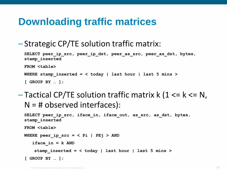
Downloading traffic matrices
– Strategic CP/TE solution traffic matrix:SELECT peer_ip_src, peer_ip_dst, peer_as_src, peer_as_dst, bytes,
stamp_inserted
FROM <table>
WHERE stamp_inserted = < today | last hour | last 5 mins >
[ GROUP BY … ];
– Tactical CP/TE solution traffic matrix k (1 <= k <= N, N = # observed interfaces):SELECT peer_ip_src, iface_in, iface_out, as_src, as_dst, bytes,
stamp_inserted
FROM <table>
WHERE peer_ip_src = < Pi | PEj > AND
iface_in = k AND
stamp_inserted = < today | last hour | last 5 mins >
[ GROUP BY … ];

35© 2010 Cisco Systems, Inc./Cariden Technologies, Inc..
Further information
– http://www.pmacct.net/lucente_pmacct_uknof14.pdf
AS-PATH radius, Communities filter, asymmetric routing
Entities on the provider IP address space
Auto-discovery and automation
– http://www.pmacct.net/building_traffic_matrices_n49.pdf http://www.pmacct.net/pmacct_peering_epf5.pdf
Building traffic matrices to support peering decisions
– http://wiki.pmacct.net/OfficialExamples
Quick-start guide to setup a NetFlow/sFlow+BGP collector instance, implementation notes, etc.

© 2010 Cisco Systems, Inc./Cariden Technologies, Inc.. 36
Network Planning

37© 2010 Cisco Systems, Inc./Cariden Technologies, Inc..
Comprehensive Traffic Management
Architecture& Engineering
(Days to Months)
Operations(Minutes to Hours)
Planning(1 to 5 Years)
Offline Online (Configs,…) (SNMP,…)
Strategic Planning
Infrastructure
Monitoring
Design Analysis
Failure Analysis
Strategic TE
RFO Analysis
Tactical TE

38© 2010 Cisco Systems, Inc./Cariden Technologies, Inc..
Common & Wasteful (Core Topologies)
• Link capacity at each ladder section set as twice traffic in that section
• 1:1 protection: 50% of infrastructure for backup
• Ring is upgraded en masse even if one side empty
• Hard to add a city to the core, bypasses (express links) avoided because of complexity
• 1:1. And some infrastructure lightly used
Blue is one physical pathOrange is another pathEdge is dually connected

39© 2010 Cisco Systems, Inc./Cariden Technologies, Inc..
N:1 Savings
• 1:1 Protection$100 carrying capacity requires $200 expenditure
• 2:1$100 carrying capacity requires $150 expenditure
• 15%-20% in practice
• E.g. national backbone costing $100M (capex+opex) saves $15M-$20M
• Instead of upgrading all elements upgrade the bottleneck
• Put in express route in bottleneck region
• 10%-20% savings are common
versus
versus

40© 2010 Cisco Systems, Inc./Cariden Technologies, Inc..
N:1 Costs
• Physical diversity not present/cheap
However, usually present at high traffic points (e.g., no diversity in far away provinces but yes in capital regions)
• Engineering/architecture considerations
E.g., how effectively balance traffic
• Planning considerations
Subject of this talk
41© 2010 Cisco Systems, Inc./Cariden Technologies, Inc..
Planning Methodologies
• Monitoring per link statistics doesn‟t cut it
• Planning needs to be topology aware
• Failure modes should be considered
• Blurs old boundaries between planning, engineering and operations

42© 2010 Cisco Systems, Inc./Cariden Technologies, Inc..
Failure Planning
Simulate using external traffic projections
Planning receives traffic projections, wants to
determine what buildout is necessary
Worst case view
Failure that can cause congestion in RED
Failure impact view
Potential congestion under failure in RED Perform topology What-If analysis
Scenario:
43© 2010 Cisco Systems, Inc./Cariden Technologies, Inc..
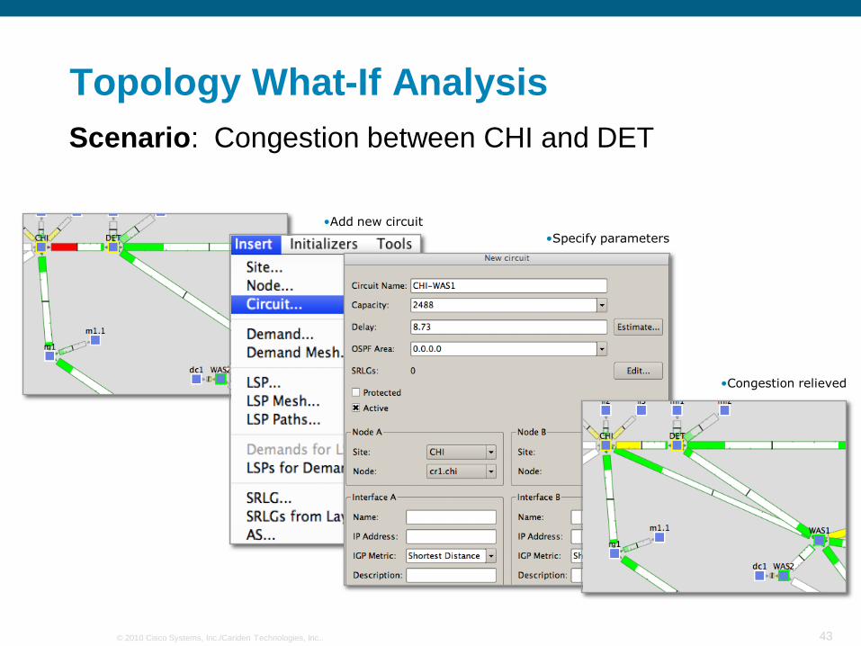
Topology What-If Analysis
•Specify parameters
•Congestion relieved
•Add new circuit
Congestion between CHI and DETScenario:

44© 2010 Cisco Systems, Inc./Cariden Technologies, Inc..
Evaluate New Services, Growth,…
Product marketing expects 4 Gbps growth in SF
based on some promotion
Scenario:
•Add 4Gbps to those flows
•Identify flows for new customer
•Congested link in RED
•Simulate results

© 2010 Cisco Systems, Inc./Cariden Technologies, Inc.. 45
Optimization/Traffic Engineering

46© 2010 Cisco Systems, Inc./Cariden Technologies, Inc..
Network Optimization
• Network Optimization encompasses network engineering and traffic engineering
Network engineering
Manipulating your network to suit your traffic
Traffic engineering
Manipulating your traffic to suit your network
• Whilst network optimization is an optional step, all of the preceding steps are essential for:
Comparing network engineering and TE approaches
MPLS TE tunnel placement and IP TE

47© 2010 Cisco Systems, Inc./Cariden Technologies, Inc..
Network Optimization: Questions
• What optimization objective?
• Which approach?
IGP TE or MPLS TE
• Strategic or tactical?
• How often to re-optimise?
• If strategic MPLS TE chosen:
Core or edge mesh
Statically (explicit) or dynamically established tunnels
Tunnel sizing
Online or offline optimization
Traffic sloshing

48© 2010 Cisco Systems, Inc./Cariden Technologies, Inc..
IP Traffic Engineering: The Problem
• Conventional IP routing usespure destination-basedforwarding where pathcomputation is based upon asimple additive metric
Bandwidth availability is nottaken into account
• Some links may be congested while others are underutilized
• The traffic engineering problem can be defined as an optimization problem
Definition – “optimization problem”: A computational problem in which the objective is to find the best of all possible solutions
Given a fixed topology and a fixed source-destinationmatrix of traffic to be carried, what routing of flowsmakes most effective use of aggregate or per class(Diffserv) bandwidth?
How do we define most effective … ?
•Path for R1 to R8 traffic =
•Path for R2 to R8 traffic =
•R8
•R2
•R1
•R3
•R4
•R5 •R6
•R7

49© 2010 Cisco Systems, Inc./Cariden Technologies, Inc..
IP Traffic Engineering: The objective
• What is the primary optimization objective?
Either …
minimizing maximum utilization in normal working (non-failure) case
Or …
minimizing maximum utilization under single element failure conditions
• Understanding the objective is important in understanding where different traffic engineering options can help and in which cases more bandwidth is required
Other optimization objectives possible: e.g. minimize propagation delay, apply routing policy …
• Ultimate measure of success is cost saving
• In this asymmetrical topology, if the demands
from XY > OC3, traffic engineering can help to
distribute the load when all links are working
•OC48
•OC48
•OC48 •OC48
•OC3
•OC12
•OC12
•A
•B
•C
•X
•D
•Y
•OC12
•OC12
•OC48
•OC48
•OC48 •OC48
•OC3
•OC12
•OC12
•A
•B
•C
•X
•D
•Y
• However, in this topology when optimization goal
is to minimize bandwidth for single element
failure conditions, if the demands from XY >
OC3, TE cannot help - must upgrade link XB

50© 2010 Cisco Systems, Inc./Cariden Technologies, Inc..
Traffic Engineering Limitations
• TE cannot create capacity
e.g. “V-O-V” topologies allow no scope strategic TE if optimizing for failure case
Only two directions in each “V” or “O” region – no routing choice for minimizing failure utilization
• Other topologies may allow scope for TE in failure case
As case study later demonstrates
51© 2010 Cisco Systems, Inc./Cariden Technologies, Inc..
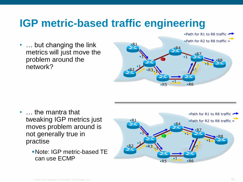
IGP metric-based traffic engineering
• … but changing the link metrics will just move the problem around the network?
• … the mantra that tweaking IGP metrics just moves problem around is not generally true in practise
Note: IGP metric-based TE can use ECMP
•1
•1
•1
•1
•1
•1
•1•3 •R8
•R2
•R1
•R3
•R4
•R5 •R6
•R7
•Path for R1 to R8 traffic =
•Path for R2 to R8 traffic =
•1
•1
•1
•1
•1
•1
•1•2 •R8
•R2
•R1
•R3
•R4
•R5 •R6
•R7
•Path for R1 to R8 traffic =
•Path for R2 to R8 traffic =

52© 2010 Cisco Systems, Inc./Cariden Technologies, Inc..
IGP metric-based traffic engineering
• Significant research efforts ...
B. Fortz, J. Rexford, and M. Thorup, “Traffic Engineering With Traditional IP Routing Protocols”, IEEE Communications Magazine, October 2002.
D. Lorenz, A. Ordi, D. Raz, and Y. Shavitt, “How good can IP routing be?”, DIMACS Technical, Report 2001-17, May 2001.
L. S. Buriol, M. G. C. Resende, C. C. Ribeiro, and M. Thorup, “A memeticalgorithm for OSPF routing” in Proceedings of the 6th INFORMS Telecom, pp. 187188, 2002.
M. Ericsson, M. Resende, and P. Pardalos, “A genetic algorithm for the weight setting problem in OSPF routing” J. Combinatorial Optimization, volume 6, no. 3, pp. 299-333, 2002.
W. Ben Ameur, N. Michel, E. Gourdin et B. Liau. Routing strategies for IP networks. Telektronikk, 2/3, pp 145-158, 2001.
…

53© 2010 Cisco Systems, Inc./Cariden Technologies, Inc..
IGP metric-based traffic engineering:Case study
• Proposed OC-192U.S. Backbone
• Connect Existing Regional Networks
• Anonymized (by permission)
54© 2010 Cisco Systems, Inc./Cariden Technologies, Inc..
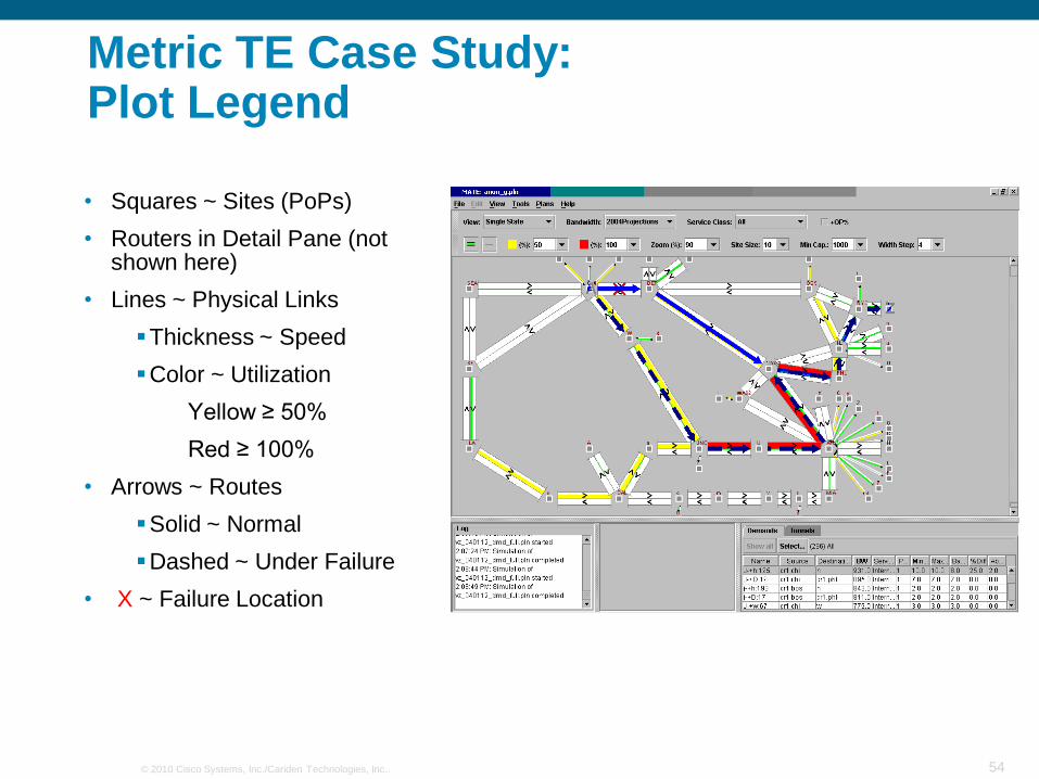
Metric TE Case Study:Plot Legend
• Squares ~ Sites (PoPs)
• Routers in Detail Pane (not shown here)
• Lines ~ Physical Links
Thickness ~ Speed
Color ~ Utilization
Yellow ≥ 50%
Red ≥ 100%
• Arrows ~ Routes
Solid ~ Normal
Dashed ~ Under Failure
• X ~ Failure Location
55© 2010 Cisco Systems, Inc./Cariden Technologies, Inc..
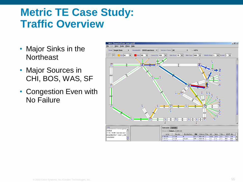
Metric TE Case Study:Traffic Overview
• Major Sinks in the Northeast
• Major Sources in CHI, BOS, WAS, SF
• Congestion Even with No Failure
56© 2010 Cisco Systems, Inc./Cariden Technologies, Inc..
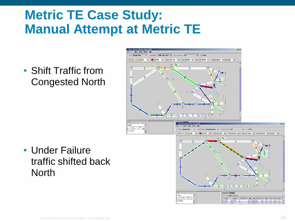
Metric TE Case Study:Manual Attempt at Metric TE
• Shift Traffic from Congested North
• Under Failure traffic shifted back North

57© 2010 Cisco Systems, Inc./Cariden Technologies, Inc..
Metric TE Case Study:Worst Case Failure View
• Enumerate Failures
• Display Worst Case Utilization per Link
• Links may be under Different Failure Scenarios
• Central Ring+ Northeast Require Upgrade

58© 2010 Cisco Systems, Inc./Cariden Technologies, Inc..
Metric TE Case Study:New Routing Visualisation
• ECMP in congested region
• Shift traffic to outer circuits
• Share backup capacity: outer circuits fail into central ones
• Change 16 metrics
• Remove congestion
Normal(121% -> 72%)
Worst case link failure(131% -> 86%)
59© 2010 Cisco Systems, Inc./Cariden Technologies, Inc..
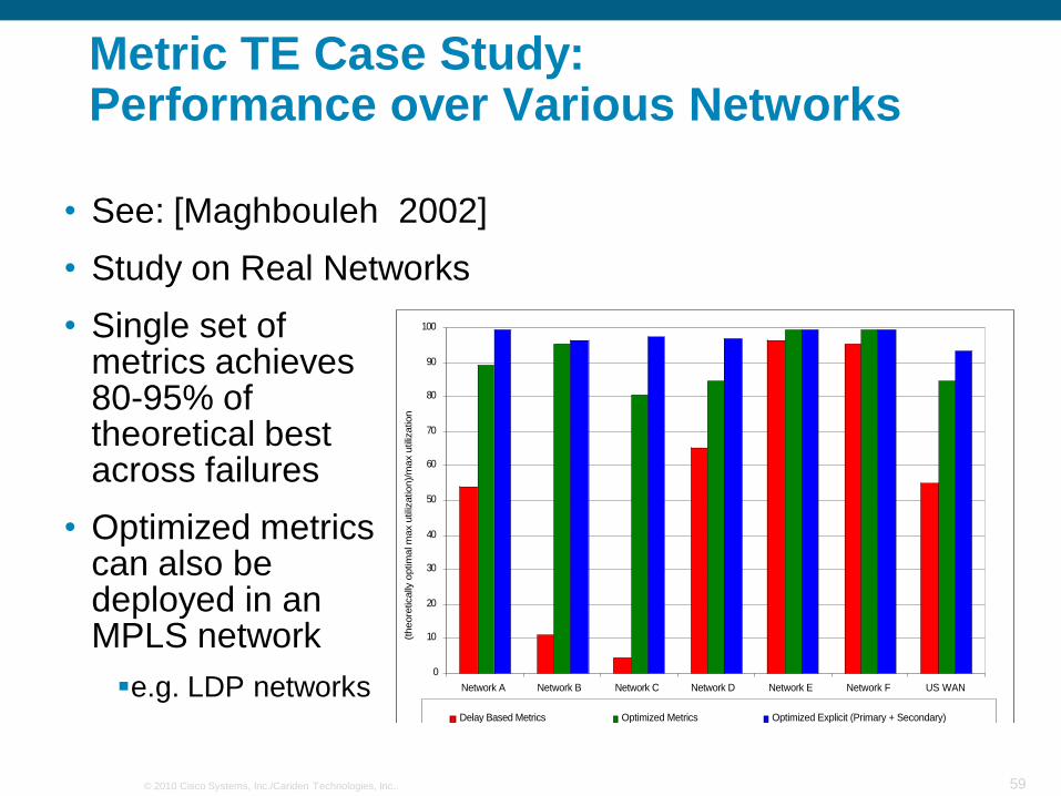
Metric TE Case Study:Performance over Various Networks
• See: [Maghbouleh 2002]
• Study on Real Networks
• Single set of metrics achieves 80-95% of theoretical best across failures
• Optimized metrics can also be deployed in an MPLS network
e.g. LDP networks0
10
20
30
40
50
60
70
80
90
100
Network A Network B Network C Network D Network E Network F US WAN
Demo
(theore
tically
optim
al m
ax u
tiliz
ation)/
max u
tiliz
ation
Delay Based Metrics Optimized Metrics Optimized Explicit (Primary + Secondary)
60© 2010 Cisco Systems, Inc./Cariden Technologies, Inc..
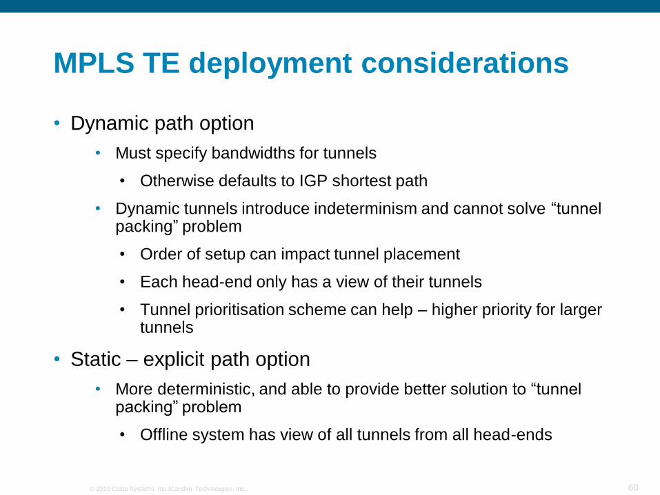
MPLS TE deployment considerations
• Dynamic path option
• Must specify bandwidths for tunnels
• Otherwise defaults to IGP shortest path
• Dynamic tunnels introduce indeterminism and cannot solve “tunnel packing” problem
• Order of setup can impact tunnel placement
• Each head-end only has a view of their tunnels
• Tunnel prioritisation scheme can help – higher priority for larger tunnels
• Static – explicit path option
• More deterministic, and able to provide better solution to “tunnel packing” problem
• Offline system has view of all tunnels from all head-ends
61© 2010 Cisco Systems, Inc./Cariden Technologies, Inc..
Tunnel Sizing
• Tunnel sizing is key …
Needless congestion if actual load >> reserved bandwidth
Needless tunnel rejection if reservation >> actual load
Enough capacity for actual load but not for the tunnel reservation
• Actual heuristic for tunnel sizing will depend upon dynamism of tunnel sizing
Need to set tunnel bandwidths dependent upon tunnel traffic characteristic over optimisation period

62© 2010 Cisco Systems, Inc./Cariden Technologies, Inc..
Tunnel Sizing
• Online vs. offline sizing:
Online sizing: autobandwidth
• Router automatically adjusts reservation (up or down) based on traffic observed in previous time interval
• Tunnel bandwidth is not persistent (lost on reload)
• Can suffer from “bandwidth lag”
Offline sizing
• Statically set reservation to percentile (e.g. P95) of expected max load
• Periodically readjust – not in real time, e.g. daily, weekly, monthly
“online sizing: bandwidth lag”

63© 2010 Cisco Systems, Inc./Cariden Technologies, Inc..
Tunnel Sizing
• When to re-optimise?
Event driven optimisation, e.g. on link or node failures
• Won‟t re-optimise due to tunnel changes
Periodically
• Tunnel churn if optimisation periodicity high
• Inefficiencies if periodicity too low
• Can be online or offline

64© 2010 Cisco Systems, Inc./Cariden Technologies, Inc..
Strategic Deployment: Core Mesh
• Reduces number of tunnels required
• Can be susceptible to “traffic-sloshing”
65© 2010 Cisco Systems, Inc./Cariden Technologies, Inc..
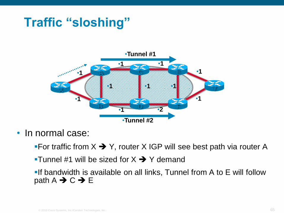
Traffic “sloshing”
• In normal case:
For traffic from X Y, router X IGP will see best path via router A
Tunnel #1 will be sized for X Y demand
If bandwidth is available on all links, Tunnel from A to E will follow path A C E
B
•1
X
A E
F
C
D
Y
•1
•1 •1 •1
•1
•2•1
•1 •1
•1
•Tunnel #2
•Tunnel #1

66© 2010 Cisco Systems, Inc./Cariden Technologies, Inc..
Traffic “sloshing”
• In failure of link A-C:
For traffic from X Y, router X IGP will now see best path via router B
However, if bandwidth is available, tunnel from A to E will be re-established over path A B D C E
Tunnel #2 will not be sized for X Y demand
Bandwidth may be set aside on link A B for traffic which is now taking different path
B
•1
X
A E
F
C
D
Y
•1
•1 •1 •1
•1
•2•1
•1 •1
•1
•Tunnel #2
•Tunnel #1

67© 2010 Cisco Systems, Inc./Cariden Technologies, Inc..
Traffic “sloshing”
• Forwarding adjacency (FA) could be used to overcome traffic sloshing
Normally, a tunnel only influences the FIB of its head-end and other nodes do not see it
With FA the head-end advertises the tunnel in its IGP LSP
Tunnel #1 could always be made preferable over tunnel #2 for traffic from X Y
• Holistic view of traffic demands (core traffic matrix) and routing (in failures if necessary) is necessary to understand impact of TE
B
•1
X
A E
F
C
D
Y
•1
•1 •1 •1
•1
•2•1
•1 •1
•1
•Tunnel #2
•Tunnel #1

68© 2010 Cisco Systems, Inc./Cariden Technologies, Inc..
Traffic “sloshing”
• Forwarding adjacency could be used to overcome traffic sloshing
Normally, a tunnel only influences the FIB of its head-end
other nodes do not see it
With Forwarding Adjacency the head-end advertises the tunnel in its IGP LSP
Tunnel #1 could always be made preferable over tunnel #2 for traffic from X Y
B
•1
X
A E
F
C
D
Y
•1
•1 •1 •1
•1
•2•1
•1 •1
•1
•Tunnel #2
•Tunnel #1

69© 2010 Cisco Systems, Inc./Cariden Technologies, Inc..
TE Case Study 1: Global Crossing*
• Global IP backbone
Excluded Asia due to migration project
• MPLS TE (CSPF)
• Evaluate IGP Metric Optimization
Using 4000 demands, representing 98.5% of total peak traffic
• Topology:
highly meshed
(*) Presented at TERENA Networking Conference, June 2004

70© 2010 Cisco Systems, Inc./Cariden Technologies, Inc..
TE Case Study 1: Global Crossing
• Comparison:
Delay-based Metrics
MPLS CSPF
Optimized Metrics
• Normal Utilizations
no failures
• 200 highest utilized links in the network
• Utilizations:
Delay-based: RED
CSPF: BLACK
Optimized: BLUE

71© 2010 Cisco Systems, Inc./Cariden Technologies, Inc..
TE Case Study 1: Global Crossing
• Worst-Case Utilizations
single-link failures
core network
263 scenarios
• Results:
Delay-based metrics cause congestions
CSPF fills links to 100%
Metric Optimization achieves
<90% worst-case utilizations

72© 2010 Cisco Systems, Inc./Cariden Technologies, Inc..
TE Case Study 2: Deutsche Telekom*
(*) Presented at Nanog 33, by Martin Horneffer (DT)

73© 2010 Cisco Systems, Inc./Cariden Technologies, Inc..
TE Case Study 3
• Anonymous network…
• TE Options:
Dynamic MPLS
Mesh of CSPF tunnels in the core network
“Sloshing” causes congestion under failure scenarios
Metric Based TE
Explicit Pri. + Sec. LSPs
Failures Considered
Single-circuit, circuit+SRLG, circuit+SRLG+Node
Plot is for single-circuit failures
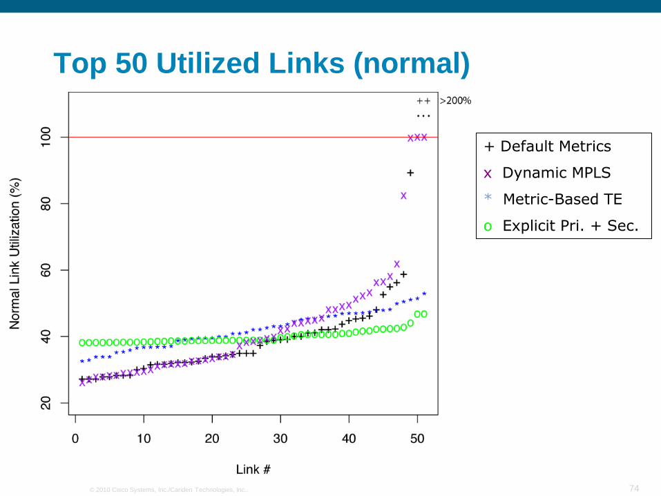
74© 2010 Cisco Systems, Inc./Cariden Technologies, Inc..
Top 50 Utilized Links (normal)
+ Default Metrics
x Dynamic MPLS
* Metric-Based TE
o Explicit Pri. + Sec.

75© 2010 Cisco Systems, Inc./Cariden Technologies, Inc..
Top 50 Utilized Links (failures)
+ Default Metrics
x Dynamic MPLS
* Metric-Based TE
o Explicit Pri. + Sec.

76© 2010 Cisco Systems, Inc./Cariden Technologies, Inc..
Traffic Engineering Experiences
• Some meshing in the topology required to save costs
• Metric TE
Simple to deploy
Requires uniform capacities (within regions)
• MPLS TE
Dynamic tunnels
• Very resilient and efficient
• Tunnel mesh and sizing issues
Explicit tunnels
• Very efficient
• Requires complex solutions to deploy
© 2010 Cisco Systems, Inc./Cariden Technologies, Inc.. 77
Planning for LFA FRR

78© 2010 Cisco Systems, Inc./Cariden Technologies, Inc..
Per-Prefix LFA Algorithm
• For IGP route D1, S‟s primary path is link SF.
• S checks for each neighbor N (<>F) whether ND1 < NS + SD1 (Eq1)
“does the path from the neighbor to D1 avoid me?”
If so, it is a loop-free alternate (LFA) to my primary path to D1
S F
C
E
D1
D2

79© 2010 Cisco Systems, Inc./Cariden Technologies, Inc..
One backup path per primary path
• Default tie-break
1. Prefer primary over secondary
2. Prefer lowest backup path metric
3. Prefer linecard disjointness
4. Prefer node disjointness
• CLI to customize the tie-break policy
Default is recommended. Simplicity.
80© 2010 Cisco Systems, Inc./Cariden Technologies, Inc..
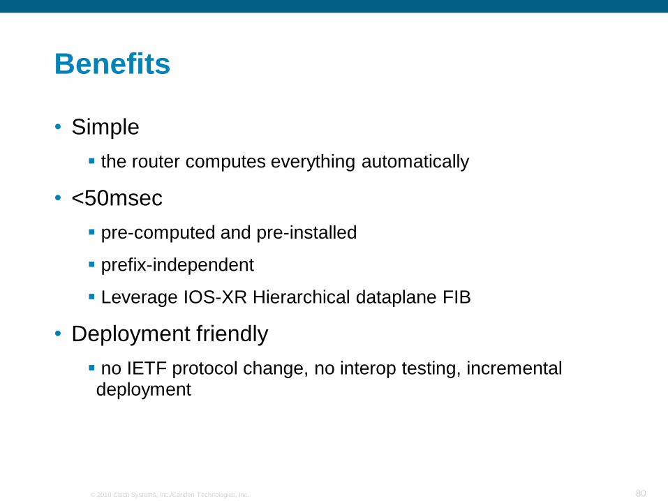
Benefits
• Simple
the router computes everything automatically
• <50msec
pre-computed and pre-installed
prefix-independent
Leverage IOS-XR Hierarchical dataplane FIB
• Deployment friendly
no IETF protocol change, no interop testing, incremental deployment

81© 2010 Cisco Systems, Inc./Cariden Technologies, Inc..
Benefits
• Good Scaling
• No degradation on IGP convergence for primary paths
• Capacity Planning
• Node Protection (Guaranteed or De Facto)
an LFA can be chosen on the basis of the guaranteed-node protection
simulation indicate that most link-based LFA‟s anyway avoid the node (ie. De Facto Node Protection)

82© 2010 Cisco Systems, Inc./Cariden Technologies, Inc..
Constraints
• Topology dependent
availability of a backup path depends on topology
Is there a neighbor which meets Eq1?
83© 2010 Cisco Systems, Inc./Cariden Technologies, Inc..
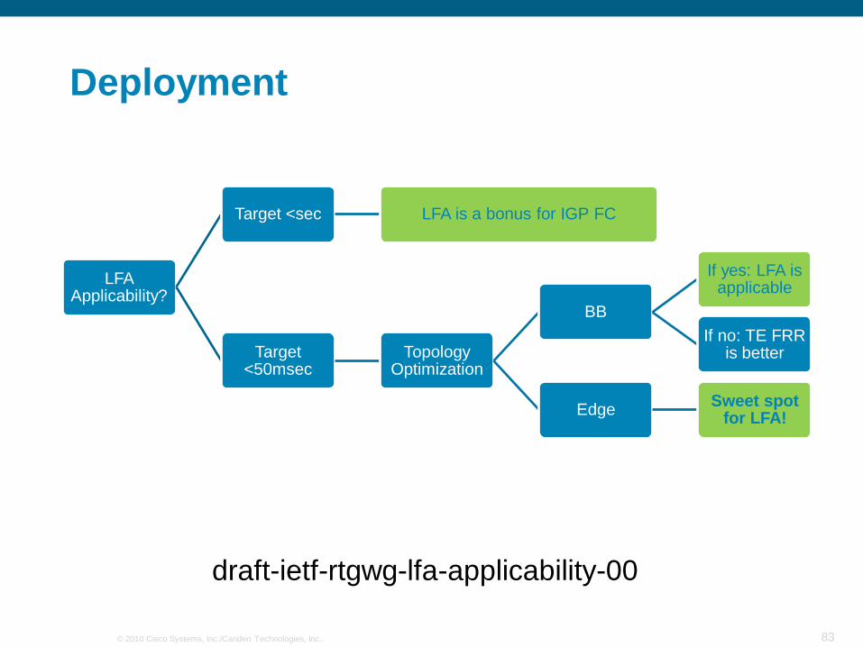
Deployment
LFA Applicability?
Target <sec LFA is a bonus for IGP FC
Target <50msec
Topology Optimization
BB
If yes: LFA is applicable
If no: TE FRR is better
EdgeSweet spot
for LFA!
draft-ietf-rtgwg-lfa-applicability-00
84© 2010 Cisco Systems, Inc./Cariden Technologies, Inc..
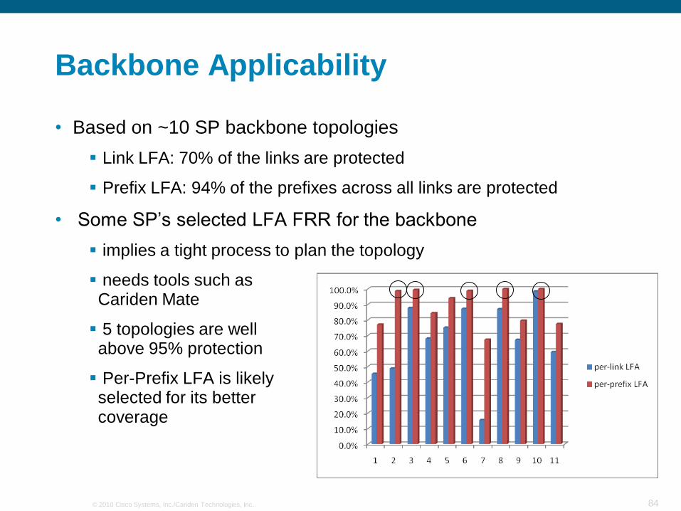
Backbone Applicability
• Based on ~10 SP backbone topologies
Link LFA: 70% of the links are protected
Prefix LFA: 94% of the prefixes across all links are protected
• Some SP‟s selected LFA FRR for the backbone
implies a tight process to plan the topology
needs tools such as Cariden Mate
5 topologies are wellabove 95% protection
Per-Prefix LFA is likelyselected for its bettercoverage
85© 2010 Cisco Systems, Inc./Cariden Technologies, Inc..
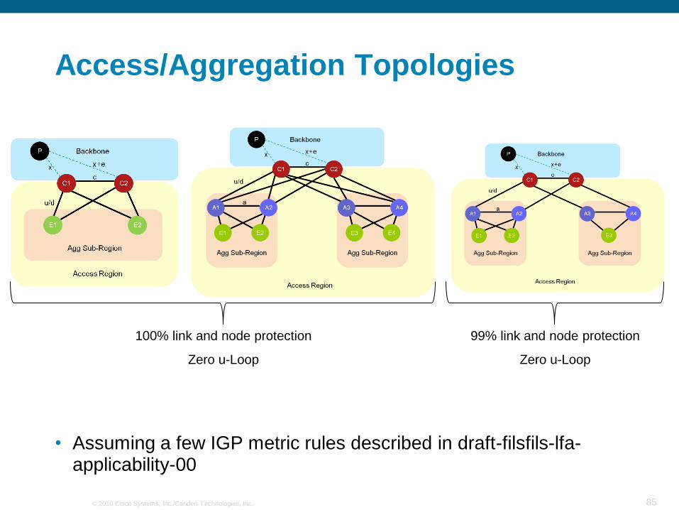
Access/Aggregation Topologies
• Assuming a few IGP metric rules described in draft-filsfils-lfa-applicability-00
100% link and node protection
Zero u-Loop
99% link and node protection
Zero u-Loop

86© 2010 Cisco Systems, Inc./Cariden Technologies, Inc..
• A reference to consult if interested
• Slight modification to slide 17. The solution will be called “Remote LFA” and an ietf draft should be released in the next weeks.

© 2010 Cisco Systems, Inc./Cariden Technologies, Inc.. 87
IP/Optical Integration

88© 2010 Cisco Systems, Inc./Cariden Technologies, Inc..
SRLG
• To backup R1R4, R2 or R3?
• R2: disjoint optical path!
R1
O1
O3
O2
O4 O5
R2 R3 R4
R5

89© 2010 Cisco Systems, Inc./Cariden Technologies, Inc..
Circuit ID
• Multi-Layer Planning optimization requires mapping circuits between L3 and L0 topologies
• Circuit ID acts as glue between L3 topology and underlying L0 topology
• Other applications:
troubleshooting
disjointness
R1
O1
O3
O2
O4 O5
R2 R3 R4
R5
Link O1-123
O1
O3
O2
O4 O5
Link O1-123

90© 2010 Cisco Systems, Inc./Cariden Technologies, Inc..
SRLG and Circuit ID Discovery
• Current: retrieve info from optical NMS and map the SRLG‟s to L3 topology. Labor intensive.
• Near future: automated discovery from the router L3 control plane thanks to L3/L0 integration

91© 2010 Cisco Systems, Inc./Cariden Technologies, Inc..
Fasted DWDM provisioning

© 2010 Cisco Systems, Inc./Cariden Technologies, Inc.. 92
A final example

93© 2010 Cisco Systems, Inc./Cariden Technologies, Inc..
Network Design
• For Mobile backbone network
Fictional (German) topology
• IP over optical
• Projected Traffic Matrix
• Objectives:
Cost effective
Low delay
IPFRR LFA coverage
• Topology:
IP/Optical
6 core sites
94© 2010 Cisco Systems, Inc./Cariden Technologies, Inc..
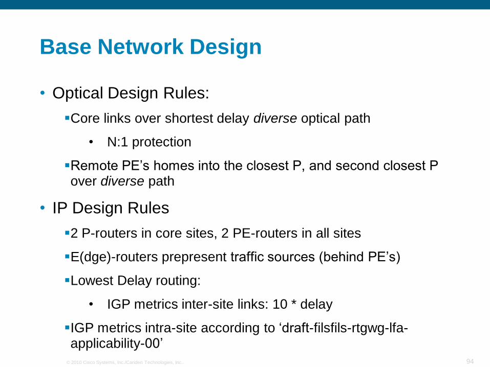
Base Network Design
• Optical Design Rules:
Core links over shortest delay diverse optical path
• N:1 protection
Remote PE‟s homes into the closest P, and second closest P over diverse path
• IP Design Rules
2 P-routers in core sites, 2 PE-routers in all sites
E(dge)-routers prepresent traffic sources (behind PE‟s)
Lowest Delay routing:
• IGP metrics inter-site links: 10 * delay
IGP metrics intra-site according to „draft-filsfils-rtgwg-lfa-applicability-00‟

95© 2010 Cisco Systems, Inc./Cariden Technologies, Inc..
Optical network (geographic/schematic)

96© 2010 Cisco Systems, Inc./Cariden Technologies, Inc..
Circuit routing over optical network
• 6 core sites
• IP circuits
routed over
shortest delay
paths
• Note: fiber
used for more
than one
circuit around
Frankfurt

97© 2010 Cisco Systems, Inc./Cariden Technologies, Inc..
SRLGs on IP layer
110% Utilization due
to SRLG failure

98© 2010 Cisco Systems, Inc./Cariden Technologies, Inc..
Create diverse routing on optical layer
• Move
Dusseldorf-
Stuttgart away
from Frankfurt
• Move
Dusseldorf-
Frankfurt away
from Cologne

99© 2010 Cisco Systems, Inc./Cariden Technologies, Inc..
Add remote PE’s
• 1. Kiel
Closest PE is Hamburg
2nd closest Dusseldorf
Diverse!
100© 2010 Cisco Systems, Inc./Cariden Technologies, Inc..
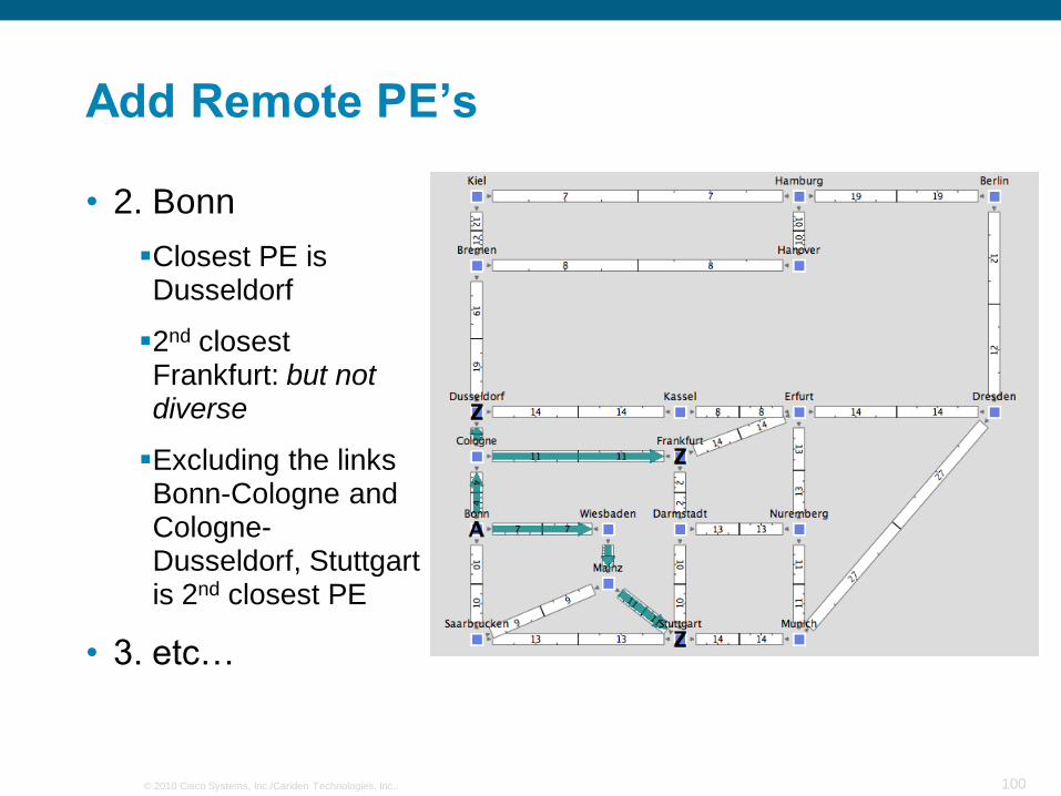
Add Remote PE’s
• 2. Bonn
Closest PE is Dusseldorf
2nd closest Frankfurt: but not diverse
Excluding the links Bonn-Cologne and Cologne-Dusseldorf, Stuttgart is 2nd closest PE
• 3. etc…

101© 2010 Cisco Systems, Inc./Cariden Technologies, Inc..
Final IP topology
• Highest utilization
due to any circuit
or SRLG failure is
90%
• Saving of 20%
due to diversity of
Dusseldorf-
Frankfurt and
Dusseldorf-
Stuttgart

102© 2010 Cisco Systems, Inc./Cariden Technologies, Inc..
IPFRR LFA’s
• 75% of
interface
traffic has an
LFA available
• Some inter-
site links are
not protected
due to ring
topology
LFA‟s for all prefixes
No LFA for any prefix
LFA‟s for some prefixes

103© 2010 Cisco Systems, Inc./Cariden Technologies, Inc..
IPFRR LFA’s: site view
• LFA applicability
draft section
3.3: Square

© 2010 Cisco Systems, Inc./Cariden Technologies, Inc.. 104
Conclusion

105© 2010 Cisco Systems, Inc./Cariden Technologies, Inc..
Conclusion
• Capacity Planning is essential for enforcing SLA with min capacity
• Router vendors to provide input data
Traffic Matrix (neftlow v9)
Base Topology (LSDB)
QoS and Routing Policy
near-future: IP/Optical integrated data
• Planning tools to provide
Traffic Matrix Deduction
Simulation and Optimization engine
Consulting service
• SP to put the process in practice

106© 2010 Cisco Systems, Inc./Cariden Technologies, Inc..
References
• [Filsfils and Evans 2005]
Clarence Filsfils and John Evans, "Deploying Diffserv in IP/MPLS Backbone Networks for Tight SLA Control", IEEE Internet Computing*, vol. 9, no. 1, January 2005, pp. 58-65
http://www.employees.org/~jevans/papers.html
• [Deploy QoS]
Deploying IP and MPLS QoS for multiservice networks: theory and practice, By John Evans, Clarence Filsfils
http://books.google.be/books?id=r6121tRwA6sC&pg=PA76&lpg=PA76&dq=book+deploying+qos+sp+filsfils&source=bl&ots=xauvtXLg3X&sig=f1NGddiXrZ_FAA3ZbRtoxVDiwPc&hl=en&ei=grDaTL6nBY3CsAOOsoHIBw&sa=X&oi=book_result&ct=result&resnum=1&ved=0CBUQ6AEwAA#v=onepage&q&f=false
• [Telkamp 2003]
Thomas Telkamp, “Backbone Traffic Management”, Asia Pacific IP Experts Conference (Cisco), November 4th, 2003, Shanghai, P.R. China
http://www.cariden.com/technology/white_papers/entry/backbone_traffic_management
• [Vardi 1996]
Y. Vardi. “Network Tomography: Estimating Source-Destination Traffic Intensities from Link Data.” J.of the American Statistical Association, pages 365–377, 1996.
• [Zhang et al. 2004]
Yin Zhang, Matthew Roughan, Albert Greenberg, David Donoho, Nick Duffield, Carsten Lund, Quynh Nguyen, and David Donoho, “How to Compute Accurate Traffic Matrices for Your Network in Seconds”, NANOG29, Chicago, October 2004.
See also: http://public.research.att.com/viewProject.cfm?prjID=133/

107© 2010 Cisco Systems, Inc./Cariden Technologies, Inc..
References
• [Gunnar et al.]
Anders Gunnar (SICS), Mikael Johansson (KTH), Thomas Telkamp (Global Crossing). “Traffic Matrix Estimation on a Large IP Backbone - A Comparison on Real Data”
http://www.cariden.com/technology/white_papers/entry/traffic_matrix_estimation_on_a_large_ip_backbone_-_a_comparison_on_real_dat
• [Telkamp 2009]
“How Full is Full?”, DENOG 2009
http://www.cariden.com/technology/white_papers/entry/how_full_is_full
• [Maghbouleh 2002]
Arman Maghbouleh, “Metric-Based Traffic Engineering: Panacea or Snake Oil? A Real-World Study”, NANOG 26, October 2002, Phoenix
http://www.cariden.com/technologies/papers.html
• [Cao 2004]
Jin Cao, William S. Cleveland, and Don X. Sun. “Bandwidth Estimation for Best-Effort Internet Traffic”
Statist. Sci. Volume 19, Number 3 (2004), 518-543.