Capacity of MIMO Indoor
7
Capacity Analysis of MIMO-OFDM Broadband Channels In Populated Indoor Environments Jishu DasGupta 1 , Karla Ziri-Castro 2 and Hajime Suzuki 3 1 Faculty of Sciences, University of So uthern Queensland Toowoomba, Australia Tel: +61-7-4631 5564, Email: [email protected] 2 Faculty of Engineering and Surveying, University of Southern Queensland Toowoomba, Australia Tel: +61-7-4631 2503, Email: [email protected] 3 CSIRO ICT Centre Sydney, Australia Tel: 61-2- 9372 4121, Email: [email protected] Abstract —This paper presents the results of dynamic channel capacity measurements for a multiple-input multiple-output orthogonal frequency division multiplexing (MIMO-OFDM) system in two populated indoor environments with and without line-of-sight (LoS). The experiment used 4 sending and 4 receiving antennas and 114 sub-carriers at 5 GHz as per draft IEEE 802.11n. MIMO-OFDM channel capacity is analysed both with fixed receiver signal-to-noise ratio (SNR) and fixed transmitter (Tx) power criteria. It is found that fixed SNR capacity increased while fixed Tx power capacity decreased in both environments by the presence of pedestrian. It is also revealed that the spread of the capacity cumulative distribution function (CDF) increased due to the pedestrians in both environments with both criteria. I. I NTRODUCTION When multiple-input multiple-output (MIMO) systems are deployed in suitable rich scattering environments, a significant capacity gain can be observed due to the assurance of multipath propagation [1], [2]. MIMO systems are particularly attractive with narrowband channels where multipath tends to create independent channels even with small antenna spacing (approximately a half-wavelength). Hence the combination of MIMO with orthogonal frequency division multiplexing (OFDM), where a wide frequency bandwidth can be efficiently separated into multiple channels at independent sub-carriers, is considered as a strong candidate for the next generation bandwidth-efficient wireless systems [3]. Sufficiently rich multipath signal propagation has been found in MIMO or MIMO-OFDM channels operating within indoor and their capacity has been analysed for static environments [4], [5], [6]. However, temporal channel variations can occur as a result of personnel, industrial machinery, vehicles and various equipment moving within the indoor environment. Recently, effort has been made to model human body shadowing effects on MIMO channels [7], [8]. The time varying effects on the propagation channel within populated indoor environments depends on different pedestrian traffic conditions, and is related to the particular type of environment considered [9]. Notwithstanding previous studies, a systematic measurement campaign to characterize time-varying pedestrian movement effects in MIMO-OFDM channels has not yet fully investigated. Characterizing channel variations caused by the relative positioning of pedestrians is essential in the study of indoor MIMO-OFDM wireless networks. This paper investigates the dynamic channel capacity of a MIMO-OFDM channel using four transmitters and four receivers (4x4) within two populated indoor environments through systematic experimental measurements. The characteristics of actual temporal variation and correlation analysis have been reported in [10] and [11], respectively. This paper focuses on the analysis of capacity cumulative distribution functions (CDFs). Following, Section 2 presents an overview of the fundamentals of MIMO-OFDM channel capacity. The description of the measurement equipment and measurement sites are presented in Section 3. Section 4 summarises the experimental set up. Section 5 provides the time-varying results and analysis for the 4x4 MIMO-OFDM channel capacity, followed by the conclusions in Section 6. II. MIMO-OFDM CHANNEL CAPACITY Characterisation of MIMO-OFDM channel capacity in various indoor environments plays a key role to determine the performance of MIMO-OFDM systems. The MIMO-OFDM channel capacity is given by ( ) ∑ ∑ = = + = f t n k n j t k j f n f n C 1 1 2 1 log 1 ρλ (1) Here C is the normalised capacity in bit/sec/hertz, n f is the number of OFDM sub-carriers, n t is the number of Tx antennas, ρ is the average signal to noise ratio (SNR) and λ j is the eigenvalue of H( f k )H( f k ) H . H( f k ) is the normalised channel coefficient matrix at sub-carrier f k and H denotes Hermitian transpose. Two different criteria are employed to estimate the MIMO- OFDM channel capacity in this paper. The first assumes an interference-limited system where transmitting power can be adjusted without a limit to provide a fixed average SNR at the receivers. The averaging of SNR and normalisation of
Transcript of Capacity of MIMO Indoor

8/9/2019 Capacity of MIMO Indoor
http://slidepdf.com/reader/full/capacity-of-mimo-indoor 1/6
Capacity Analysis of MIMO-OFDM Broadband
Channels In Populated Indoor EnvironmentsJishu DasGupta1, Karla Ziri-Castro2 and Hajime Suzuki3
1Faculty of Sciences, University of Southern Queensland
Toowoomba, AustraliaTel: +61-7-4631 5564, Email: [email protected]
2Faculty of Engineering and Surveying, University of Southern Queensland
Toowoomba, Australia
Tel: +61-7-4631 2503, Email: [email protected] 3CSIRO ICT Centre
Sydney, Australia
Tel: 61-2- 9372 4121, Email: [email protected]
Abstract —This paper presents the results of dynamic channel
capacity measurements for a multiple-input multiple-output
orthogonal frequency division multiplexing (MIMO-OFDM)
system in two populated indoor environments with and without
line-of-sight (LoS). The experiment used 4 sending and 4receiving antennas and 114 sub-carriers at 5 GHz as per draft
IEEE 802.11n. MIMO-OFDM channel capacity is analysed both
with fixed receiver signal-to-noise ratio (SNR) and fixed
transmitter (Tx) power criteria. It is found that fixed SNR
capacity increased while fixed Tx power capacity decreased in
both environments by the presence of pedestrian. It is also
revealed that the spread of the capacity cumulative distribution
function (CDF) increased due to the pedestrians in both
environments with both criteria.
I. I NTRODUCTION
When multiple-input multiple-output (MIMO) systems are
deployed in suitable rich scattering environments, a
significant capacity gain can be observed due to the assuranceof multipath propagation [1], [2]. MIMO systems are
particularly attractive with narrowband channels wheremultipath tends to create independent channels even with
small antenna spacing (approximately a half-wavelength).
Hence the combination of MIMO with orthogonal frequency
division multiplexing (OFDM), where a wide frequency
bandwidth can be efficiently separated into multiple channels
at independent sub-carriers, is considered as a strong
candidate for the next generation bandwidth-efficient wireless
systems [3].
Sufficiently rich multipath signal propagation has been
found in MIMO or MIMO-OFDM channels operating within
indoor and their capacity has been analysed for staticenvironments [4], [5], [6]. However, temporal channel
variations can occur as a result of personnel, industrial
machinery, vehicles and various equipment moving within the
indoor environment. Recently, effort has been made to model
human body shadowing effects on MIMO channels [7], [8].
The time varying effects on the propagation channel within
populated indoor environments depends on different
pedestrian traffic conditions, and is related to the particular
type of environment considered [9]. Notwithstanding previous
studies, a systematic measurement campaign to characterize
time-varying pedestrian movement effects in MIMO-OFDM
channels has not yet fully investigated. Characterizing
channel variations caused by the relative positioning of pedestrians is essential in the study of indoor MIMO-OFDM
wireless networks.This paper investigates the dynamic channel capacity of a
MIMO-OFDM channel using four transmitters and four
receivers (4x4) within two populated indoor environments
through systematic experimental measurements. Thecharacteristics of actual temporal variation and correlation
analysis have been reported in [10] and [11], respectively.
This paper focuses on the analysis of capacity cumulative
distribution functions (CDFs). Following, Section 2 presents
an overview of the fundamentals of MIMO-OFDM channel
capacity. The description of the measurement equipment andmeasurement sites are presented in Section 3. Section 4
summarises the experimental set up. Section 5 provides the
time-varying results and analysis for the 4x4 MIMO-OFDMchannel capacity, followed by the conclusions in Section 6.
II. MIMO-OFDM CHANNEL CAPACITY
Characterisation of MIMO-OFDM channel capacity invarious indoor environments plays a key role to determine the
performance of MIMO-OFDM systems. The MIMO-OFDM
channel capacity is given by
( )∑∑
= =
+=
f t n
k
n
j t
k j
f n
f
nC
1 1
2 1log1 ρλ
(1)
Here C is the normalised capacity in bit/sec/hertz, n f is the
number of OFDM sub-carriers, nt is the number of Txantennas, ρ is the average signal to noise ratio (SNR) and λ j is
the eigenvalue of H( f k )H( f k ) H
. H( f k ) is the normalised channel
coefficient matrix at sub-carrier f k and H denotes Hermitian
transpose.
Two different criteria are employed to estimate the MIMO-OFDM channel capacity in this paper. The first assumes an
interference-limited system where transmitting power can be
adjusted without a limit to provide a fixed average SNR at the
receivers. The averaging of SNR and normalisation of

8/9/2019 Capacity of MIMO Indoor
http://slidepdf.com/reader/full/capacity-of-mimo-indoor 2/6
channel coefficient matrix is performed over all MIMO sub-
channels and over all OFDM sub-carriers.
Fig. 1. CSIRO ICT center MIMO-OFDM channel sounder (Left: Tx,
Right Rx)
This corresponds to the system where co-channel
interference is the limiting factor for the system capacity, andthe enough Tx power is reserved to cater every locations
within the coverage area. The second assumes a power-
limited system where the transmitting power is fixed. In thiscase the averaging of SNR and normalisation of channel
coefficient matrix is performed over all MIMO sub-channels,
over all OFDM sub-carriers, over all 100 measurement
samples, and over all different number of pedestrian
(described in IV). Fixed Tx power criteria incorporates the
effects of the reduction of power due to body shadowing by
the pedestrian. This criterion is more suitable for the analysis
of WLAN system where the transmitting power is typically
fixed. Note that the actual transmitting power during the
measurement was fixed to one setting during LoSmeasurement and was changed to another setting during
NLoS measurement, in order to provide adequate SNR for
both measurements, and hence the comparison of fixed Tx
power LoS and NLoS measurement has an ambiguity.
However, this does not cause problems in analysing the
effects of pedestrian for each environment, which is the focus
of this paper.
III. MEASUREMENT EQUIPMENT AND SITES
The measurements were performed using the MIMO-
OFDM channel sounder developed by CSIRO ICT Centre [5].
The channel sounder operates at a carrier frequency of 5.24
GHz and has an operational bandwidth of 40 MHz. Thenumber of OFDM sub-carriers and the sub-carrier spacing are
114 (108 data and 6 pilots) and 312.5 kHz, respectively, as
per the IEEE 802.11n draft standard [12]. It has 4 transmitters
with a maximum gain of 23 dB per channel and 4 receivers
with 3 dB noise figure over the 40 MHz bandwidth. A
photograph of the equipment is shown in Fig. 1.Measurements were performed on the furniture free ground
floor rooms in the CSIRO ICT Centre, Marshfield, Sydney.
Two different Rx locations were considered (1) line-of-sight
(LoS), where Tx and Rx are located inside the same 57 m2
laboratory, and (2) non-LoS (NLoS), where Rx is located in
an adjacent 30 m2
office, see Fig. 2.
IV. EXPERIMENT DESCRITPION
Pedestrian trajectories for LoS and NLoS experiments are
shown in Fig. 2. During the LoS scenario pedestrians walked
along a 6 m trajectory within the laboratory while during the
NLoS scenario pedestrians walked along the adjacent 12 m
corridor.
Tx
12m
5m
Rx
6m
6m
Office
NLoS
LOS
Laoratory
Atrium5m
2.5 m
Rx
16 m
10m
Standing Pedestrain
Walking Pedestrian
Walking Path
Plaster Board
Window
Fig. 2. Measurement sites.
Data have been collected under controlled pedestrian traffic
conditions. Four different scenarios were considered: vacant,
one, two and three pedestrians walking along the indicated
trajectories. Complex channel coefficients for each of 16MIMO sub-channels at 114 OFDM sub-carriers werecollected at 100 time samples while pedestrians were walking,
standing, or vacant.
V. RESULTS
A sample of MIMO-OFDM channel coefficient power is
shown in Fig. 3 (NLoS) and Fig. 4 (LoS), where x axis is the
frequency (MHz) and y axis is the relative power (dB). Fromthe graphs more severe frequency selective fading is observed
in NLoS when comparing with LoS.
8/9/2019 Capacity of MIMO Indoor
http://slidepdf.com/reader/full/capacity-of-mimo-indoor 3/6
-40
-20
0
20Tx1-Rx1
-40
-20
0
20Tx2-Rx1
-40
-20
0
20Tx3-Rx1
-20 - 10 0 10 20-40
-20
0
20Tx4-Rx1
Tx1-Rx2
Tx2-Rx2
Tx3-Rx2
-20 -10 0 10 20
Tx4-Rx2
Tx1-Rx3
Tx2-Rx3
Tx3-Rx3
-20 - 10 0 10 20
Tx4-Rx3
Tx1-Rx4
Tx2-Rx4
Tx3-Rx4
-20 - 10 0 10 20
Frequency (MHz)
R e l a t i v e p o w e r ( d
B )
Tx4-Rx4
Fig. 3. A sample of the 4x4 MIMO-OFDM channels (NLoS)
-40
-20
0
20Tx1-Rx1
-40
-20
0
20Tx2-Rx1
-40
-20
0
20Tx3-Rx1
-20 - 10 0 10 20-40
-20
0
20 Tx4-Rx1
Tx1-Rx2
Tx2-Rx2
Tx3-Rx2
-20 -10 0 10 20
Tx4-Rx2
Tx1-Rx3
Tx2-Rx3
Tx3-Rx3
-20 - 10 0 10 20
Tx4-Rx3
Tx1-Rx4
Tx2-Rx4
Tx3-Rx4
-20 - 10 0 10 20
Frequency (MHz)
R e l a t i v e p o w e r ( d B )
Tx4-Rx4
Fig. 4. A sample of the 4x4 MIMO-OFDM sub-channels (LoS)
0 20 40 60 80 10012
12.5
13
13.5
14
14.5
15
15.5
Sample index
A v e r a g e c a p a c
i t y ( b p s / H z )
0
1
2
3
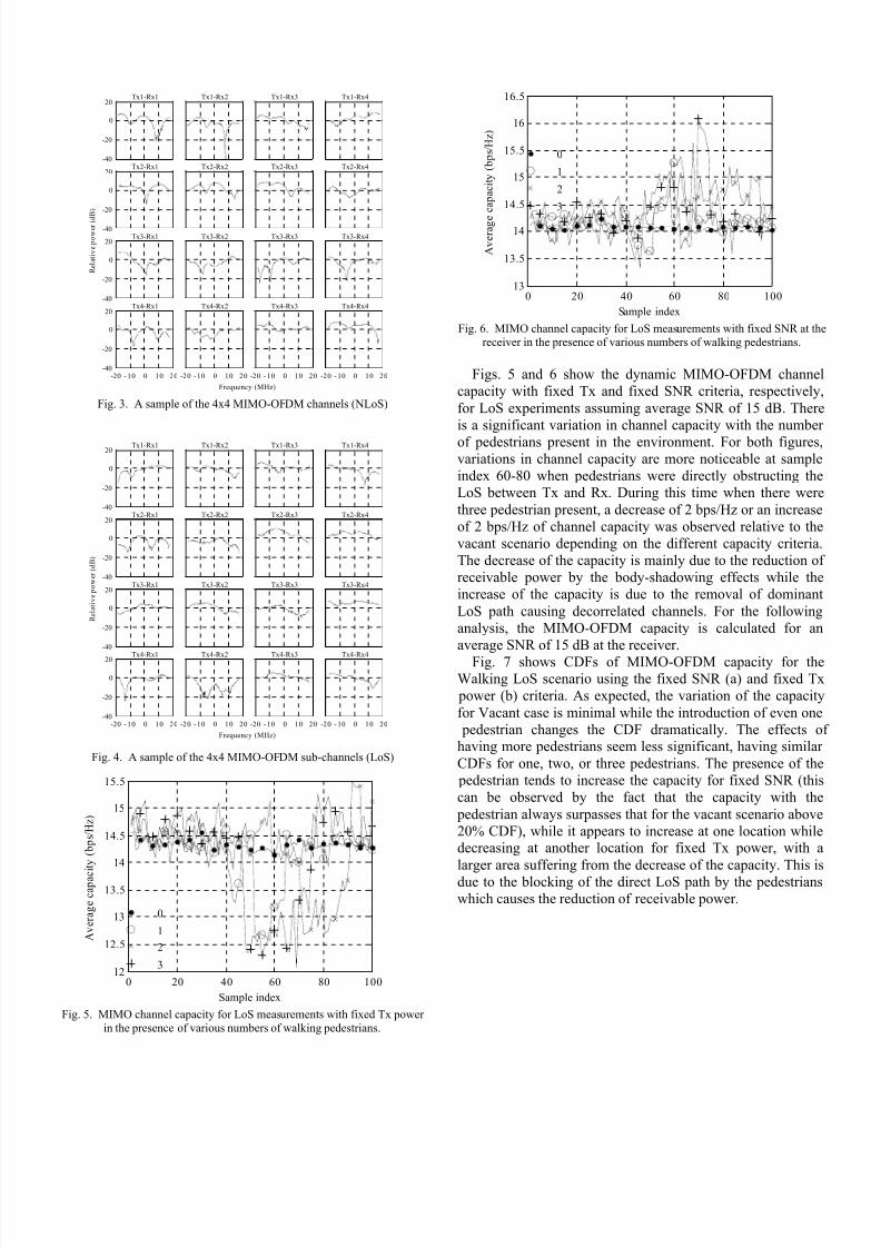
Fig. 5. MIMO channel capacity for LoS measurements with fixed Tx power
in the presence of various numbers of walking pedestrians.
0 20 40 60 80 10013
13.5
14
14.5
15
15.5
16
16.5
Sample index
A v e r a g e
c a p a c i t y ( b p s / H z )
0
1
2
3
Fig. 6. MIMO channel capacity for LoS measurements with fixed SNR at the
receiver in the presence of various numbers of walking pedestrians.
Figs. 5 and 6 show the dynamic MIMO-OFDM channel
capacity with fixed Tx and fixed SNR criteria, respectively,
for LoS experiments assuming average SNR of 15 dB. There
is a significant variation in channel capacity with the number
of pedestrians present in the environment. For both figures,variations in channel capacity are more noticeable at sample
index 60-80 when pedestrians were directly obstructing the
LoS between Tx and Rx. During this time when there were
three pedestrian present, a decrease of 2 bps/Hz or an increase
of 2 bps/Hz of channel capacity was observed relative to the
vacant scenario depending on the different capacity criteria.
The decrease of the capacity is mainly due to the reduction of
receivable power by the body-shadowing effects while the
increase of the capacity is due to the removal of dominant
LoS path causing decorrelated channels. For the following
analysis, the MIMO-OFDM capacity is calculated for an
average SNR of 15 dB at the receiver.
Fig. 7 shows CDFs of MIMO-OFDM capacity for the
Walking LoS scenario using the fixed SNR (a) and fixed Tx
power (b) criteria. As expected, the variation of the capacity
for Vacant case is minimal while the introduction of even one
pedestrian changes the CDF dramatically. The effects of having more pedestrians seem less significant, having similar
CDFs for one, two, or three pedestrians. The presence of the
pedestrian tends to increase the capacity for fixed SNR (this
can be observed by the fact that the capacity with the
pedestrian always surpasses that for the vacant scenario above
20% CDF), while it appears to increase at one location whiledecreasing at another location for fixed Tx power, with a
larger area suffering from the decrease of the capacity. This is
due to the blocking of the direct LoS path by the pedestrians
which causes the reduction of receivable power.

8/9/2019 Capacity of MIMO Indoor
http://slidepdf.com/reader/full/capacity-of-mimo-indoor 4/6
13 13.5 14 14.5 15 15.5 16 16.5 170
10
20
30
40
50
60
70
80
90
100
MIMO-OFDM capacity (bits/ s/Hz)
C D F ( % )
Vacant
One
Two
Three
(a) Fixed SNR.
12 12.5 13 13.5 14 14.5 15 15.5 160
10
20
30
40
50
60
70
80
90
100
MIMO-OFDM capacity (bits/s /Hz)
C D F ( % )
Vacant
One
Two
Three
(b) Fixed Tx power.
Fig. 7. CDFs of MIMO-OFDM capacity for Walking LoS.
Fig. 8 shows CDFs of MIMO-OFDM capacity for the
Walking NLoS scenario. Compared to Fig. 7, the mediancapacity is increased for NLoS than LoS for both fixed SNR
or fixed Tx power. This indicates de-correlation of channels
by removing direct LoS component. Note that the typically
larger Tx power is required for NLoS case. Compared to LoS
cases, it can also be seen that the spread of CDFs is less in the
case of NLoS. This is attributed to the fact that blocking of a
particular radio path within many paths is less significant than blocking of dominant direct LoS path in LoS case.
14 14.5 15 15.5 16 16.5 170
10
20
30
40
50
60
70
80
90
100
MIMO-OFDM capacity (bits/ s/Hz)
C D F ( % )
Vacant
One
Two
Three
(a) Fixed SNR.
13 13.5 14 14.5 15 15.5 16 16.5 17 17.5 180
10
20
30
40
50
60
70
80
90
100
MIMO-OFDM capacity (bits/s/Hz)
C D F ( % )
Vacant
One
Two
Three
(b) Fixed Tx power.
Fig. 8. CDFs of MIMO-OFDM capacity for Walking NLoS.
Fig. 9 shows CDFs of MIMO-OFDM capacity for the
Standing LoS scenario. From the graph it is found that there isa capacity increase in presence of more people in the LoS
path. Comparing the spread of CDFs for Vacant case and One,
Two, or Three pedestrian case, the pedestrians are found to
cause some temporal variation even when they are simply
standing. Compared to Fig. 7, the effect of a larger number of
the pedestrians is more profound. This is attributed to the fact
that pedestrians were lined up parallel to the direct LoS in the
case of Walking, while they were lined up perpendicular to
the direct LoS in the case of standing (see Fig. 2).

8/9/2019 Capacity of MIMO Indoor
http://slidepdf.com/reader/full/capacity-of-mimo-indoor 5/6
13 13.5 14 14.5 15 15.5 160
10
20
30
40
50
60
70
80
90
100
MIMO-OFDM capacity (bits/s/Hz)
C D F ( % )
Vacant
One
Two
Three
(a) Fixed SNR.
13 13.5 14 14.5 15 15.5 160
10
20
30
40
50
60
70
80
90
100
MIMO-OFDM capacity (bits/ s/Hz)
C D F ( % )
Vacant
One
Two
Three
(b) Fixed Tx power.
Fig. 9. CDFs of MIMO-OFDM capacity for Standing LoS.
Fig. 10 shows CDFs of MIMO-OFDM capacity for
Standing NLoS cases. Unlike LoS case shown in Fig. 9, thespread of CDFs is similar between Vacant case and One, Two,
or Three pedestrian cases. This indicates that the main cause
of temporal variation in NLoS when pedestrians are simply
standing come from environment (fans, motor, fluorescent
lights, etc.)
15 15. 2 15. 4 15. 6 15.8 16 16. 2 1 6. 4 16. 6 16. 8 170
10
20
30
40
50
60
70
80
90
100
MIMO-OFDM capacity (bits/s/Hz)
C D
F ( % )
Vacant
One
Two
Three
(a) Fixed SNR.
14 14.5 15 15.5 16 16.5 170
10
20
30
40
50
60
70
80
90
100
MIMO-OFDM capacity (bits/s/Hz)
C D F ( % )
Vacant
One
Two
Three
(b) Fixed Tx power.
Fig. 10. CDFs of MIMO-OFDM capacity for Standing NLoS.
VI. CONCLUSIONS
The channel capacity of an indoor MIMO-OFDM system
was measured in the presence of nearby pedestrian trafficeffect. It has been observed that pedestrian effectssignificantly affect the theoretical maximum channel capacity
of indoor MIMO-OFDM systems. From the study of LoS and
NLoS scenarios with up to three pedestrians, the results
presented demonstrate that the spread become higher and
MIMO-OFDM channel capacity decreased or increased in the
presence of more pedestrian depending on the capacitycriteria.
Future effort should be directed at the analysis of different
types of environment, consistent data collection and
pedestrian traffic conditions, including corridors and larger
populated areas such as malls. Base on the collected data we
will design an improved model for the MIMO-OFDMchannels in the indoor environment in the presences of human.
ACKNOWLEDGMENT
The authors would like to acknowledge the CSIRO ICT
Centre personnel at Marshfield, Sydney, for providing the
MIMO-OFDM channel sounder and measurement sites.
R EFERENCES
[1] G. J. Foschini, and M. J. Gans, “On limits of wirelesscommunications in a fading environment when using multiple
antennas”, Wireless Personal Communication, vol. 6, no. 3, pp.311–335, March 1998.
[2] C. –N. Chuah, J. M. Kahn, and D. Tse, “Capacity of multi-antenna array systems in indoor wireless environment”, in Proc.
IEEE GLOBECOM , vol. 4, pp. 1894–1899, Sydney, Australia, November 1998.
[3] G. L. Stuber, J. R. Barry, S. W. McLaughlin, Y. G. Li, M. A.
Ingram, and T. G. Pratt, “Broadband MIMO-OFDM wireless
communications,” Proceedings of the IEEE , vol. 92, no. 2, pp.271-294, February 2004.
[4] J. W. Wallace, M. A. Jensen, A. Lee Swindlehurst and B. D.Jeffs, “Experimental characterization of the MIMO wireless

8/9/2019 Capacity of MIMO Indoor
http://slidepdf.com/reader/full/capacity-of-mimo-indoor 6/6
channel: data acquisition and analysis,” IEEE Transactions OnWireless Communications, vol. 2, no. 2, pp. 335 - 343, March2003.
[5] Hajime Suzuki, Thi Van Anh Tran, and Iain B. Collings,
“Characteristics of MIMO-OFDM channels in indoor environments,” EURASIP Journal on Wireless Communicationsand Networking , vol. 2007, Article ID 19728, January 2007.
[6] A. Guillén i Fàbregas, M. Guillaud, D. T. M. Slock, G. Caire, K.
Gosse, S. Rouquette, A. Ribeiro Dias, P. Bernardin, X. Miet, J.-M. Conrat, Y. Toutain, A. Peden, and Z. Li, “A MIMO-OFDMtestbed for wireless local area networks,” EURASIP Journal on Applied Signal Processing , vol. 2006, Article ID 18083, pages
1-20, DOI: 10.1155/ASP/2006/18083.[7] K. I. Ziri-Castro, W. G. Scanlon, and N. E. Evans, “Prediction
of variation in MIMO channel capacity for the populated indoor environment using a radar cross-section-based pedestrian
model,” IEEE Transactions on Wireless Communications, vol. 4,no. 3, pp. 1186-1194, May 2005.
[8] K. I. Ziri-Castro, W. G. Scanlon and F. Tofoni, “Dynamiccapacity estimation for the indoor wireless channel with MIMO
arrays and pedestrian traffic,” In Proc. 1st Joint IEI/IEE Symposium on Telecommunications Systems Research, Dublin,Ireland, November 2001.
[9] K. I. Ziri-Castro, W. G. Scanlon, and N. E. Evans, “Measured pedestrian movement and bodyworn terminal effects for theindoor channel at 5.2 GHz,” European Transactions onTelecommunications, vol. 14, pp. 529-538, November/December 2003.
[10] J. D. Gupta, K. Z. Castro, R. Addie, “Time variationcharacteristics of MIMO-OFDM broadband channels in populated indoor environments,” In Proc. of the AustralianTelecommunication Networks and Applications Conference 06 ,
pp. 430-434, December 2006.[11] Jishu Das Gupta, Karla Ziri-Castro, and Hajime Suzuki,
“Correlation analysis on MIMO-OFDM channels in populatedtime varying indoor environment,” In booklet of 10th AustralianSymposium on Antennas, p. 36, Sydney, Australia, February
2007.[12] IEEE P801.11n/D1.08, Draft Standard for InformationTechnology-Telecommunications and information exchangebetween systems-Local and metropolitan area networks-Specific
requirements-Part 11, December 2006.