CAPACITOR AND APFC SYSTEM SERVICE MANUAL...APFC should be recommended. Note that APFC should have...
23
INSTALLATION & TROUBLE SHOOTING CAPACITOR AND APFC SYSTEM SERVICE MANUAL SAFE & SURE L&T SWITCHGEAR
Transcript of CAPACITOR AND APFC SYSTEM SERVICE MANUAL...APFC should be recommended. Note that APFC should have...

INSTALLATION & TROUBLE SHOOTING
CAPACITOR AND APFC SYSTEMSERVICE MANUAL
S A F E & S U R E
L&T SWITCHGEAR
1. Please check if required kVAr of capacitors are installed.
2. Check the type of capacitor installed is suitable for application or the capacitors are derated.
3. Check if the capacitors are permanently ‘ON’. The Capacitor are not switched off when the load is not working, under such condition the average power factor is found to be lower side.
4. Check whether all the capacitors are operated in APFC depending upon the load operation.
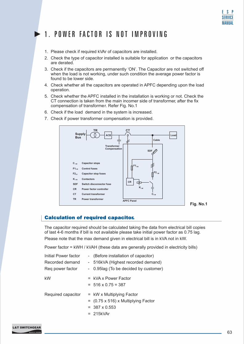
5. Check whether the APFC installed in the installation is working or not. Check the CT connection is taken from the main incomer side of transformer, after the fix compensation of transformer. Refer Fig. No.1
6. Check if the load demand in the system is increased.
7. Check if power transformer compensation is provided.
Fig. No.1
1 . P O W E R F A C T O R I S N O T I M P R O V I N G
Calculation of required capacitor.
The capacitor required should be calculated taking the data from electrical bill copies of last 4-6 months if bill is not available please take initial power factor as 0.75 lag.
Please note that the max demand given in electrical bill is in kVA not in kW.
Power factor = kWH / kVAH (these data are generally provided in electricity bills)
Initial Power factor - (Before installation of capacitor)
Recorded demand - 516kVA (Highest recorded demand)
Req power factor - 0.95lag (To be decided by customer)
kW = kVA x Power Factor
= 516 x 0.75 = 387
Required capacitor = kW x Multiplying Factor
= (0.75 x 516) x Multiplying Factor
= 387 x 0.553
= 215kVAr
LoadLoadSupplyBus
TR CT
Cable
TransformerCompensation
ACB
CR
SDF
F11-M
1-M F2
K1-M
C1-M
APFC Panel
H1F2
1-MF1
C 1-M
1-MK
SDF
CR
CT
TR Power transformer
Current transformer
Power factor controller
Switch disconnector fuse
Contactors
Capacitor stop fuses
Control fuses
Capacitor stops
Load
63S A F E & S U R E
L&T SWITCHGEAR
E S P SERVICE MANUAL
64S A F E & S U R E
L&T SWITCHGEAR
E S P SERVICE MANUAL
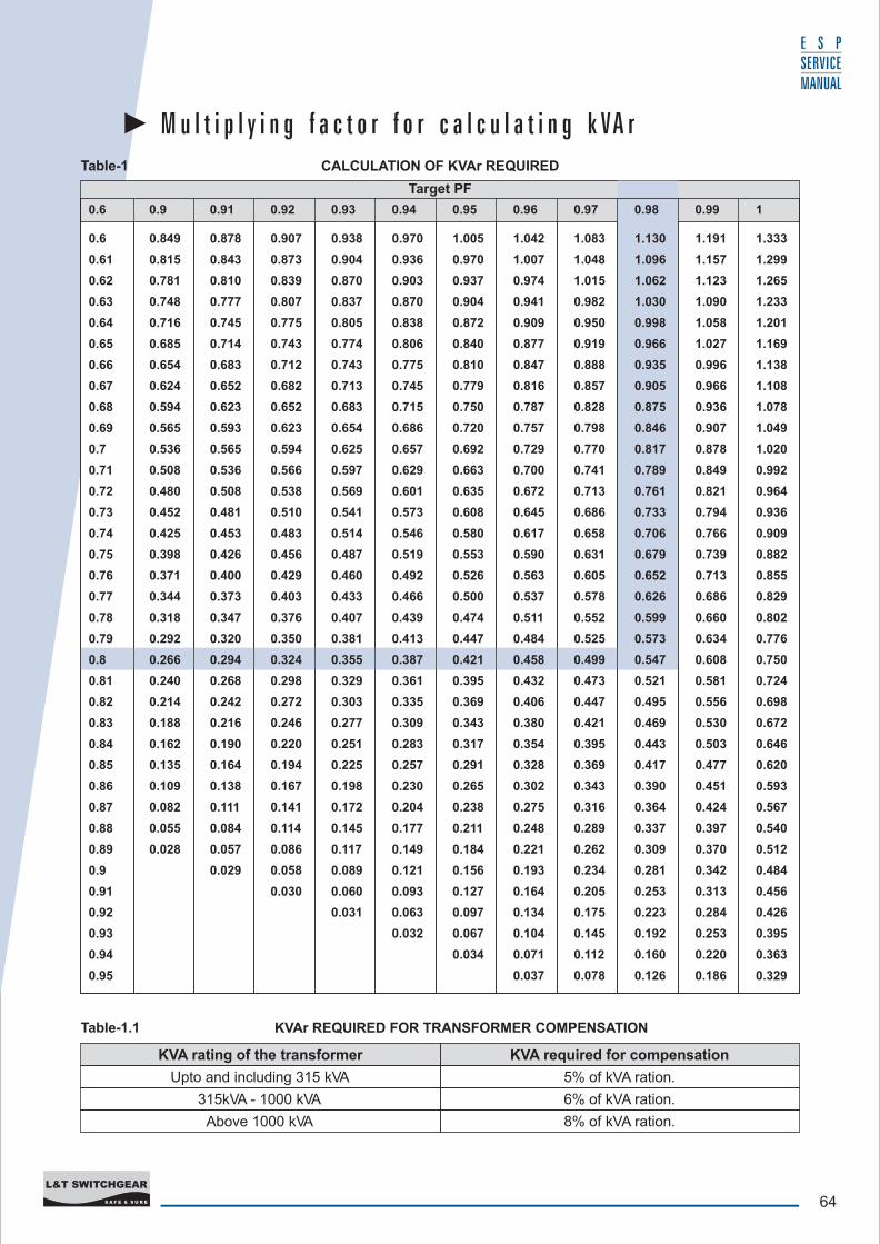
M u l t i p l y i n g f a c t o r f o r c a l c u l a t i n g k VA r
KVAr REQUIRED FOR TRANSFORMER COMPENSATIONTable-1.1
Table-1 CALCULATION OF KVAr REQUIRED
0.6 0.849 0.878 0.907 0.938 0.970 1.005 1.042 1.083 1.130 1.191 1.333
0.61 0.815 0.843 0.873 0.904 0.936 0.970 1.007 1.048 1.096 1.157 1.299
0.62 0.781 0.810 0.839 0.870 0.903 0.937 0.974 1.015 1.062 1.123 1.265
0.63 0.748 0.777 0.807 0.837 0.870 0.904 0.941 0.982 1.030 1.090 1.233
0.64 0.716 0.745 0.775 0.805 0.838 0.872 0.909 0.950 0.998 1.058 1.201
0.65 0.685 0.714 0.743 0.774 0.806 0.840 0.877 0.919 0.966 1.027 1.169
0.66 0.654 0.683 0.712 0.743 0.775 0.810 0.847 0.888 0.935 0.996 1.138
0.67 0.624 0.652 0.682 0.713 0.745 0.779 0.816 0.857 0.905 0.966 1.108
0.68 0.594 0.623 0.652 0.683 0.715 0.750 0.787 0.828 0.875 0.936 1.078
0.69 0.565 0.593 0.623 0.654 0.686 0.720 0.757 0.798 0.846 0.907 1.049
0.7 0.536 0.565 0.594 0.625 0.657 0.692 0.729 0.770 0.817 0.878 1.020
0.71 0.508 0.536 0.566 0.597 0.629 0.663 0.700 0.741 0.789 0.849 0.992
0.72 0.480 0.508 0.538 0.569 0.601 0.635 0.672 0.713 0.761 0.821 0.964
0.73 0.452 0.481 0.510 0.541 0.573 0.608 0.645 0.686 0.733 0.794 0.936
0.74 0.425 0.453 0.483 0.514 0.546 0.580 0.617 0.658 0.706 0.766 0.909
0.75 0.398 0.426 0.456 0.487 0.519 0.553 0.590 0.631 0.679 0.739 0.882
0.76 0.371 0.400 0.429 0.460 0.492 0.526 0.563 0.605 0.652 0.713 0.855
0.77 0.344 0.373 0.403 0.433 0.466 0.500 0.537 0.578 0.626 0.686 0.829
0.78 0.318 0.347 0.376 0.407 0.439 0.474 0.511 0.552 0.599 0.660 0.802
0.79 0.292 0.320 0.350 0.381 0.413 0.447 0.484 0.525 0.573 0.634 0.776
0.8 0.266 0.294 0.324 0.355 0.387 0.421 0.458 0.499 0.547 0.608 0.750
0.81 0.240 0.268 0.298 0.329 0.361 0.395 0.432 0.473 0.521 0.581 0.724
0.82 0.214 0.242 0.272 0.303 0.335 0.369 0.406 0.447 0.495 0.556 0.698
0.83 0.188 0.216 0.246 0.277 0.309 0.343 0.380 0.421 0.469 0.530 0.672
0.84 0.162 0.190 0.220 0.251 0.283 0.317 0.354 0.395 0.443 0.503 0.646
0.85 0.135 0.164 0.194 0.225 0.257 0.291 0.328 0.369 0.417 0.477 0.620
0.86 0.109 0.138 0.167 0.198 0.230 0.265 0.302 0.343 0.390 0.451 0.593
0.87 0.082 0.111 0.141 0.172 0.204 0.238 0.275 0.316 0.364 0.424 0.567
0.88 0.055 0.084 0.114 0.145 0.177 0.211 0.248 0.289 0.337 0.397 0.540
0.89 0.028 0.057 0.086 0.117 0.149 0.184 0.221 0.262 0.309 0.370 0.512
0.9 0.029 0.058 0.089 0.121 0.156 0.193 0.234 0.281 0.342 0.484
0.91 0.030 0.060 0.093 0.127 0.164 0.205 0.253 0.313 0.456
0.92 0.031 0.063 0.097 0.134 0.175 0.223 0.284 0.426
0.93 0.032 0.067 0.104 0.145 0.192 0.253 0.395
0.94 0.034 0.071 0.112 0.160 0.220 0.363
0.95 0.037 0.078 0.126 0.186 0.329
0.6 0.9 0.91 0.92 0.93 0.94 0.95 0.96 0.97 0.98 0.99 1
Target PF
KVA required for compensation
5% of kVA ration.
6% of kVA ration.
8% of kVA ration.
KVA rating of the transformer
Upto and including 315 kVA
315kVA - 1000 kVA
Above 1000 kVA
65S A F E & S U R E
L&T SWITCHGEAR
E S P SERVICE MANUAL
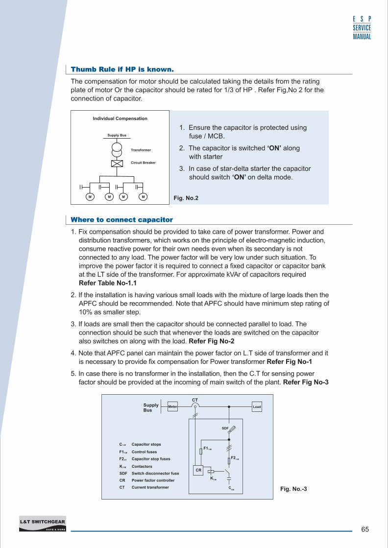
Thumb Rule if HP is known.
The compensation for motor should be calculated taking the details from the rating plate of motor Or the capacitor should be rated for 1/3 of HP . Refer Fig,No 2 for the
connection of capacitor.
Where to connect capacitor
1. Fix compensation should be provided to take care of power transformer. Power and distribution transformers, which works on the principle of electro-magnetic induction,
consume reactive power for their own needs even when its secondary is not connected to any load. The power factor will be very low under such situation. To
improve the power factor it is required to connect a fixed capacitor or capacitor bank at the LT side of the transformer. For approximate kVAr of capacitors required Refer Table No-1.1
2. If the installation is having various small loads with the mixture of large loads then the
APFC should be recommended. Note that APFC should have minimum step rating of 10% as smaller step.
3. If loads are small then the capacitor should be connected parallel to load. The
connection should be such that whenever the loads are switched on the capacitor
also switches on along with the load. Refer Fig No-2
4. Note that APFC panel can maintain the power factor on L.T side of transformer and it is necessary to provide fix compensation for Power transformer Refer Fig No-1
5. In case there is no transformer in the installation, then the C.T for sensing power
factor should be provided at the incoming of main switch of the plant. Refer Fig No-3
Fig. No.2
1. Ensure the capacitor is protected using fuse / MCB.
2. The capacitor is switched ‘ON’ along with starter
3. In case of star-delta starter the capacitor
should switch ‘ON’ on delta mode.
Individual Compensation
Supply Bus
Transformer
Circuit Breaker
M M M M
Fig. No.-3
SupplyBus
CT
Meter
CR
SDF
F11-M
1-M F2
K1-M
C1-M
H1F2
1-MF1
C1-M
1-MK
SDF
CR
CT Current transformer
Power factor controller
Switch disconnector fuse
Contactors
Capacitor stop fuses
Control fuses
Capacitor stops
Load
66S A F E & S U R E
L&T SWITCHGEAR
E S P SERVICE MANUAL
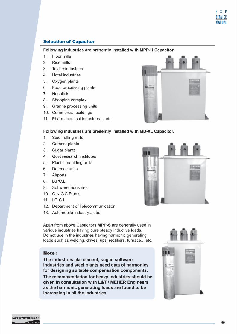
Selection of Capacitor
Following industries are presently installed with MPP-H Capacitor.
1. Floor mills
2. Rice mills
3. Textile industries
4. Hotel industries
5. Oxygen plants
6. Food processing plants
7. Hospitals
8. Shopping complex
9. Granite processing units
10. Commercial buildings
11. Pharmaceutical industries ... etc.
Following industries are presently installed with MD-XL Capacitor.
1. Steel rolling mills
2. Cement plants
3. Sugar plants
4. Govt research institutes
5. Plastic moulding units
6. Defence units
7. Airports
8. B.PC.L
9. Software industries
10. O.N.G.C Plants
11. I.O.C.L
12. Department of Telecommunication
13. Automobile Industry... etc.
Apart from above Capacitors MPP-S are generally used in various industries having pure steady inductive loads. Do not use in the industries having harmonic generating loads such as welding, drives, ups, rectifiers, furnace... etc.
Note :
The industries like cement, sugar, software industries and steel plants need data of harmonics for designing suitable compensation components.
The recommendation for heavy industries should be given in consultation with L&T / MEHER Engineers as the harmonic generating loads are found to be increasing in all the industries
67S A F E & S U R E
L&T SWITCHGEAR
E S P SERVICE MANUAL
2 . T E S T I N G O F C A PA C I T O R S AT S I T E
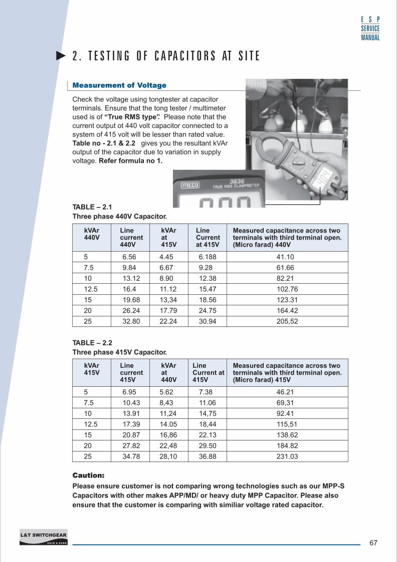
Measurement of Voltage
Check the voltage using tongtester at capacitor terminals. Ensure that the tong tester / multimeter used is of “True RMS type”. Please note that the current output ot 440 volt capacitor connected to a
system of 415 volt will be lesser than rated value.
Table no - 2.1 & 2.2 gives you the resultant kVAr output of the capacitor due to variation in supply
voltage. Refer formula no 1.
Caution:
Please ensure customer is not comparing wrong technologies such as our MPP-S
Capacitors with other makes APP/MD/ or heavy duty MPP Capacitor. Please also
ensure that the customer is comparing with similiar voltage rated capacitor.
TABLE – 2.1
Three phase 440V Capacitor.
5 6.56 4.45 6.188 41.10
7.5 9.84 6.67 9.28 61.66
10 13.12 8.90 12.38 82.21
12.5 16.4 11.12 15.47 102.76
15 19.68 13,34 18.56 123.31
20 26.24 17.79 24.75 164.42
25 32.80 22.24 30.94 205,52
TABLE – 2.2
Three phase 415V Capacitor.
Measured capacitance across two terminals with third terminal open. (Micro farad) 440V
kVAr 440V
Line current 440V
kVAr at 415V
Line Current at 415V
Measured capacitance across two terminals with third terminal open. (Micro farad) 415V
kVAr 415V
Line current 415V
kVAr at 440V
Line Current at 415V
5 6.95 5.62 7.38 46.21
7.5 10.43 8,43 11.06 69,31
10 13.91 11,24 14,75 92.41
12.5 17.39 14.05 18,44 115,51
15 20.87 16,86 22.13 138.62
20 27.82 22,48 29.50 184.82
25 34.78 28,10 36.88 231.03

68S A F E & S U R E
L&T SWITCHGEAR
E S P SERVICE MANUAL
Measurement of Current
Discharge of Capacitor
Measurement of Capacitance
The capacitor current can be measured using tong tester.
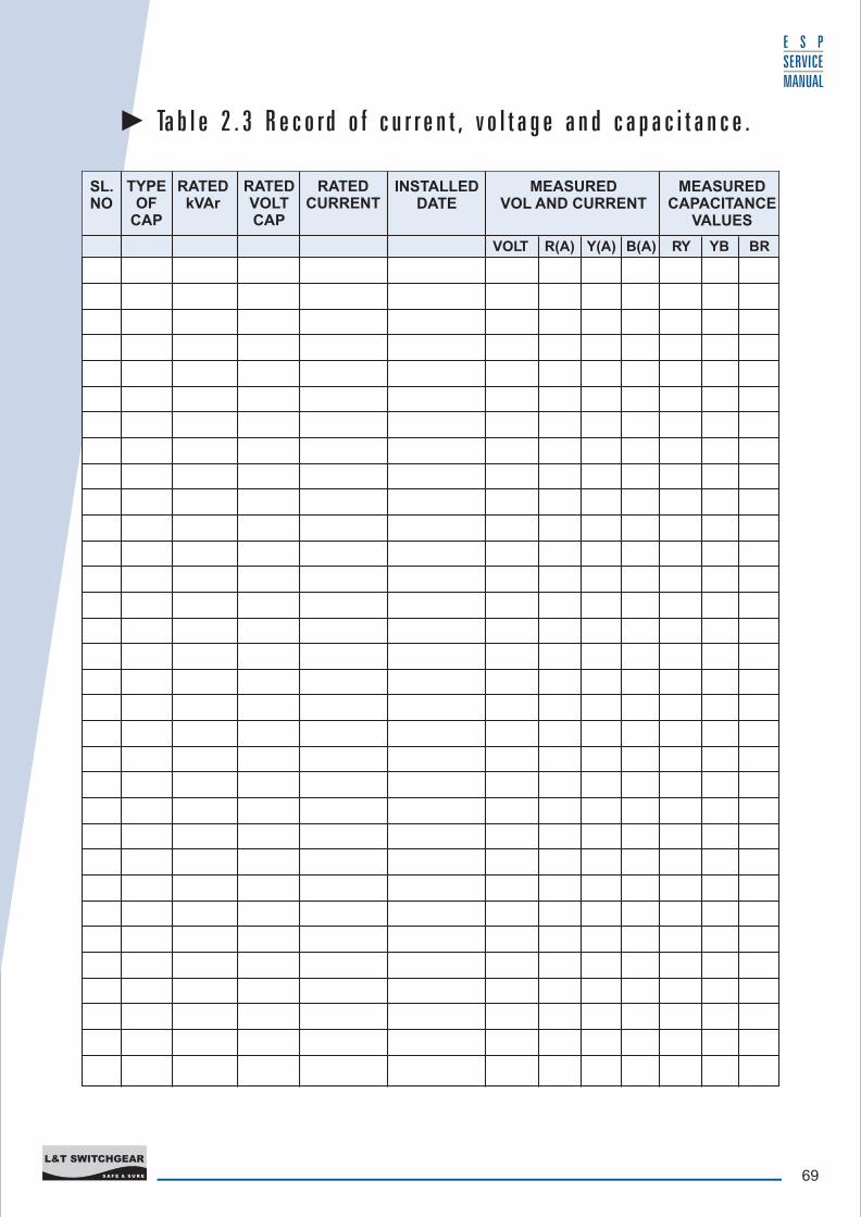
Ensure that the tong tester used is of true RMS type. ( Please note that meter contains “True RMS Clamp Meter” sticker) Make a record of measurement data of individual phase and other parameter as given in the table no 2.3.
Check wether the current measured is within the limit value with respect to supply voltage & data given in the name plate of capacitor Refer formula no -2 and 2.1 for calculation.
L.T power capacitors are provided with discharge resistor to discharge the capacitor which is limited to one min. The resistor are provided as per clause No-7.1 of IS 13340-1993.
Switch off the supply to the capacitor and wait for 1 minute and then short the terminals of capacitor to ensure that the capacitor is completely discharged. This shorting of terminals ensures the safety while handling the capacitor
Discharge of capacitor also becomes necessary for the safety of meter used for capacitance measurement.
After discharging capacitor measure capacitance between two terminals and repeat for other terminals. (RY YB and BR) Check the value from the Table No-2.1 & 2.2. Please refer to the corresponding table for rated voltage.
You can also calculate the kVAr from the formula No - 4 for the capacitor which may be derated.
Ensure that you have selected the right range for the measurement of capacitance.
Note : The capacitor is manufactured within capacitance tolerance of -5% / + 10% as per Clause No 15.3 of IS 13340 -1993.
69S A F E & S U R E
L&T SWITCHGEAR
E S P SERVICE MANUAL
Ta b l e 2 . 3 R e c o rd o f c u r r e n t , v o l t a g e a n d c a p a c i t a n c e .
VOLT R(A) Y(A) B(A) RY YB BR
SL.NO
TYPEOF
CAP
RATEDkVAr
RATEDVOLTCAP
RATEDCURRENT
INSTALLEDDATE
MEASUREDVOL AND CURRENT
MEASUREDCAPACITANCE
VALUES
70S A F E & S U R E
L&T SWITCHGEAR
E S P SERVICE MANUAL
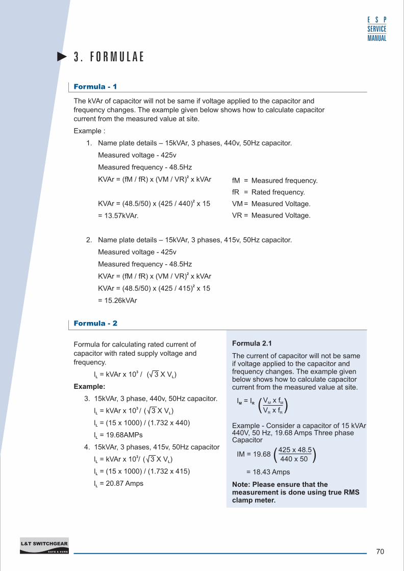
Formula - 1
The kVAr of capacitor will not be same if voltage applied to the capacitor and
frequency changes. The example given below shows how to calculate capacitor
current from the measured value at site.
Example :
1. Name plate details – 15kVAr, 3 phases, 440v, 50Hz capacitor.
Measured voltage - 425v
Measured frequency - 48.5Hz2KVAr = (fM / fR) x (VM / VR) x kVAr
2KVAr = (48.5/50) x (425 / 440) x 15
= 13.57kVAr.
2. Name plate details – 15kVAr, 3 phases, 415v, 50Hz capacitor.
Measured voltage - 425v
Measured frequency - 48.5Hz2KVAr = (fM / fR) x (VM / VR) x kVAr
2KVAr = (48.5/50) x (425 / 415) x 15
= 15.26kVAr
3 . F O R M U L A E
Formula 2.1
The current of capacitor will not be same if voltage applied to the capacitor and frequency changes. The example given below shows how to calculate capacitor current from the measured value at site.
I = IM R
Example - Consider a capacitor of 15 kVAr 440V, 50 Hz, 19.68 Amps Three phase Capacitor
IM = 19.68
= 18.43 Amps
Note: Please ensure that the measurement is done using true RMS clamp meter.
V x fM M
V x fR R( (
425 x 48.5
440 x 50( (
fM = Measured frequency.
fR = Rated frequency.
VM = Measured Voltage.
VR = Measured Voltage.
Formula for calculating rated current of
capacitor with rated supply voltage and frequency.
3l = kVAr x 10 / ( 3 X V ) L L
Example:
3. 15kVAr, 3 phase, 440v, 50Hz capacitor.3 l = kVAr x 10 / ( 3 X V ) L L
l = (15 x 1000) / (1.732 x 440) L
l = 19.68AMPsL
4. 15kVAr, 3 phases, 415v, 50Hz capacitor3l = kVAr x 10 / ( 3 X V )L L
l = (15 x 1000) / (1.732 x 415)L
l = 20.87 AmpsL
Formula - 2
71S A F E & S U R E
L&T SWITCHGEAR
E S P SERVICE MANUAL
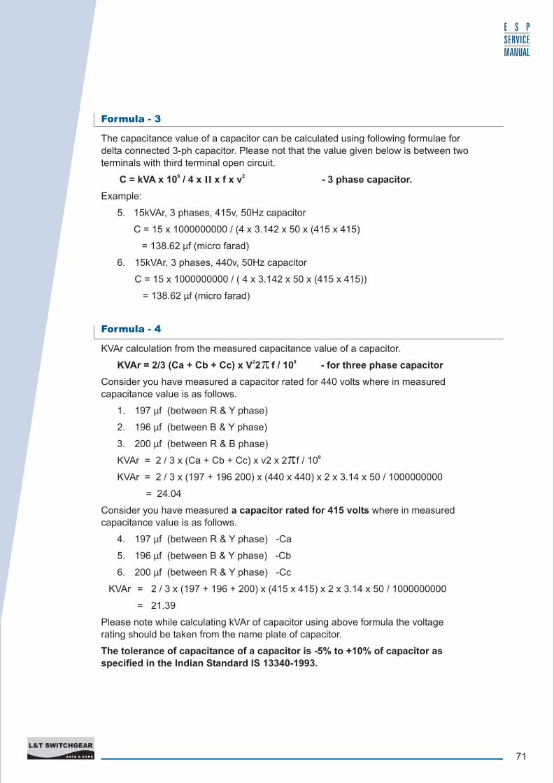
Formula - 3
Formula - 4
The capacitance value of a capacitor can be calculated using following formulae for
delta connected 3-ph capacitor. Please not that the value given below is between two
terminals with third terminal open circuit.9 2C = kVA x 10 / 4 x II x f x v - 3 phase capacitor.
Example:
5. 15kVAr, 3 phases, 415v, 50Hz capacitor
C = 15 x 1000000000 / (4 x 3.142 x 50 x (415 x 415)
= 138.62 µf (micro farad)
6. 15kVAr, 3 phases, 440v, 50Hz capacitor
C = 15 x 1000000000 / ( 4 x 3.142 x 50 x (415 x 415))
= 138.62 µf (micro farad)
KVAr calculation from the measured capacitance value of a capacitor.2 9KVAr = 2/3 (Ca + Cb + Cc) x V 2 f / 10 - for three phase capacitor
Consider you have measured a capacitor rated for 440 volts where in measured capacitance value is as follows.
1. 197 µf (between R & Y phase)
2. 196 µf (between B & Y phase)
3. 200 µf (between R & B phase)9KVAr = 2 / 3 x (Ca + Cb + Cc) x v2 x 2 f / 10
KVAr = 2 / 3 x (197 + 196 200) x (440 x 440) x 2 x 3.14 x 50 / 1000000000
= 24.04
Consider you have measured a capacitor rated for 415 volts where in measured capacitance value is as follows.
4. 197 µf (between R & Y phase) -Ca
5. 196 µf (between B & Y phase) -Cb
6. 200 µf (between R & Y phase) -Cc
KVAr = 2 / 3 x (197 + 196 + 200) x (415 x 415) x 2 x 3.14 x 50 / 1000000000
= 21.39
Please note while calculating kVAr of capacitor using above formula the voltage rating should be taken from the name plate of capacitor.
The tolerance of capacitance of a capacitor is -5% to +10% of capacitor as specified in the Indian Standard IS 13340-1993.
72S A F E & S U R E
L&T SWITCHGEAR
E S P SERVICE MANUAL
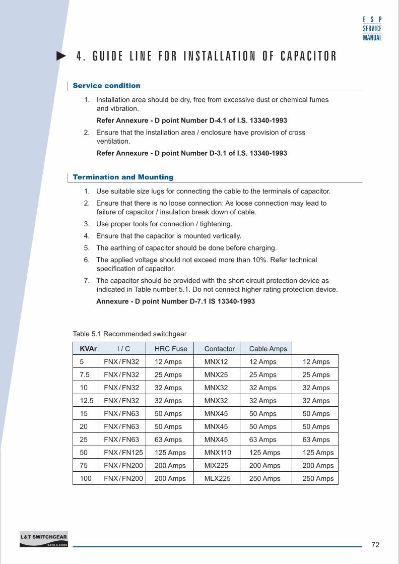
Service condition
Termination and Mounting
1. Installation area should be dry, free from excessive dust or chemical fumes
and vibration.
Refer Annexure - D point Number D-4.1 of I.S. 13340-1993
2. Ensure that the installation area / enclosure have provision of cross
ventilation.
Refer Annexure - D point Number D-3.1 of I.S. 13340-1993
1. Use suitable size lugs for connecting the cable to the terminals of capacitor.
2. Ensure that there is no loose connection: As loose connection may lead to
failure of capacitor / insulation break down of cable.
3. Use proper tools for connection / tightening.
4. Ensure that the capacitor is mounted vertically.
5. The earthing of capacitor should be done before charging.
6. The applied voltage should not exceed more than 10%. Refer technical specification of capacitor.
7. The capacitor should be provided with the short circuit protection device as indicated in Table number 5.1. Do not connect higher rating protection device.
Annexure - D point Number D-7.1 IS 13340-1993
4 . G U I D E L I N E F O R I N S T A L L A T I O N O F C A P A C I T O R
Table 5.1 Recommended switchgear
KVAr
5
7.5
10
12.5
15
20
25
50
75
100
I / C
FNX/ FN32
FNX/ FN32
FNX/ FN32
FNX/ FN32
FNX/ FN63
FNX/ FN63
FNX/ FN63
FNX/ FN125
FNX/ FN200
FNX/ FN200
HRC Fuse
12 Amps
25 Amps
32 Amps
32 Amps
50 Amps
50 Amps
63 Amps
125 Amps
200 Amps
200 Amps
Contactor
MNX12
MNX25
MNX32
MNX32
MNX45
MNX45
MNX45
MNX110
MlX225
MLX225
Cable Amps
12 Amps
25 Amps
32 Amps
32 Amps
50 Amps
50 Amps
63 Amps
125 Amps
200 Amps
250 Amps
12 Amps
25 Amps
32 Amps
32 Amps
50 Amps
50 Amps
63 Amps
125 Amps
200 Amps
250 Amps
73S A F E & S U R E
L&T SWITCHGEAR
E S P SERVICE MANUAL
Use of capacitor in APFC panel
Maintenance
1. The capacitor should be provided with suitable designed inrush current limiting
inductor coils or special capacitor duty contactors. Annexure d point no d-7.1 of
IS 13340-1993
2. Once the capacitor is switched off it should not be switched on again within 60
seconds so that the capacitor is completely discharged. The switching time in the relay provided in the APFC panel should be set for 60 seconds for individual
steps to discharge. Clause No-7.1 of IS 13340-1993
3. If the capacitor is switched manually or if you are switching capacitors connected
in parallel with each other then “ON” delay timer (60sec) should be provided and
in case of parallel operation once again point No 1 should be taken care. Clause No-7.1 of IS 13340-1993
4. The capacitor mounted in the panel should have min gap of 25-30 mm between the capacitor and 50 mm around the capacitor to the panel enclosure.
5. In case of banking a min gap of 25mm between the phase to phase and 19mm between the phase to earth should be maintained. Ensure that the banking bus
bar is rated for 1.8 times rated current of bank.
6. The panel should have provision for cross ventilation, the louver / fan can be provided in the care Annexure d point No d-3.1 IS 13340-1993
7. For use of reactor and filter in the panel fan should be provided for cooling.
8. Short circuit protection device (HRC fuse / MCCB) should not exceed 1.8 x rated
current of capacitor.
9. In case of detuned filter banks MCCB is recommended for short circuit protection.
1. Check the current of capacitor and cable connection.
2. Tighten the connections if termination is found loose. Clean the area around the
capacitor.
3. Make use of table no-2.3 for recording the data of measurements. Check the capacitance of capacitor once in three month.
4. Disconnect capacitor drawing over 30% current than rated. Contact us on help
line for further action.
5. Disconnect the capacitor having leakage problem and replace.
74S A F E & S U R E
L&T SWITCHGEAR
E S P SERVICE MANUAL
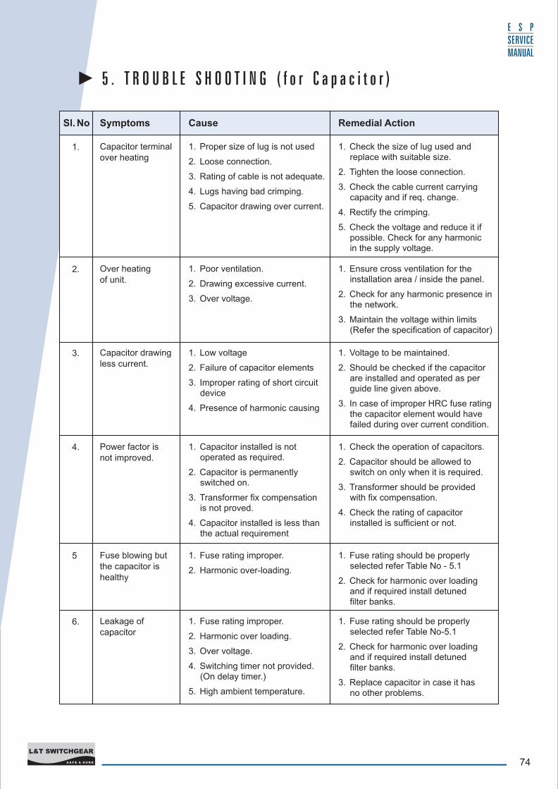
5 . T R O U B L E S H O O T I N G ( f o r C a p a c i t o r )
Sl. No Symptoms Cause Remedial Action
1. Capacitor terminalover heating
1. Proper size of lug is not used
2. Loose connection.
3. Rating of cable is not adequate.
4. Lugs having bad crimping.
5. Capacitor drawing over current.
1. Poor ventilation.
2. Drawing excessive current.
3. Over voltage.
1. Low voltage
2. Failure of capacitor elements
3. Improper rating of short circuit device
4. Presence of harmonic causing
1. Capacitor installed is not operated as required.
2. Capacitor is permanently switched on.
3. Transformer fix compensation is not proved.
4. Capacitor installed is less than the actual requirement
1. Fuse rating improper.
2. Harmonic over-loading.
1. Fuse rating improper.
2. Harmonic over loading.
3. Over voltage.
4. Switching timer not provided. (On delay timer.)
5. High ambient temperature.
2. Over heating of unit.
3. Capacitor drawingless current.
4. Power factor is not improved.
5 Fuse blowing butthe capacitor ishealthy
6. Leakage of capacitor
1. Check the size of lug used and replace with suitable size.
2. Tighten the loose connection.
3. Check the cable current carryingcapacity and if req. change.
4. Rectify the crimping.
5. Check the voltage and reduce it ifpossible. Check for any harmonic in the supply voltage.
1. Ensure cross ventilation for theinstallation area / inside the panel.
2. Check for any harmonic presence in the network.
3. Maintain the voltage within limits (Refer the specification of capacitor)
1. Voltage to be maintained.
2. Should be checked if the capacitor are installed and operated as per guide line given above.
3. In case of improper HRC fuse rating the capacitor element would have failed during over current condition.
1. Check the operation of capacitors.
2. Capacitor should be allowed to switch on only when it is required.
3. Transformer should be provided with fix compensation.
4. Check the rating of capacitor installed is sufficient or not.
1. Fuse rating should be properly selected refer Table No - 5.1
2. Check for harmonic over loading and if required install detuned filter banks.
1. Fuse rating should be properly selected refer Table No-5.1
2. Check for harmonic over loading and if required install detuned filter banks.
3. Replace capacitor in case it has no other problems.
75S A F E & S U R E
L&T SWITCHGEAR
E S P SERVICE MANUAL
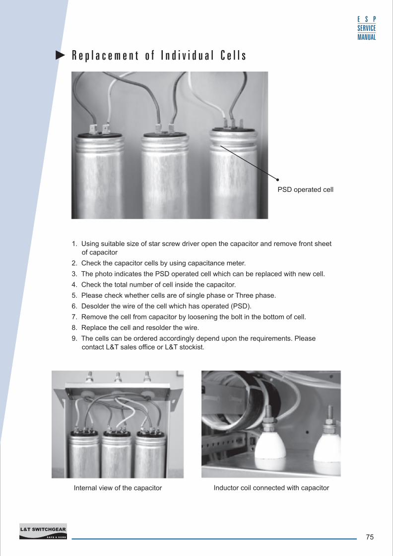
PSD operated cell
R e p l a c e m e n t o f I n d i v i d u a l C e l l s
Inductor coil connected with capacitorInternal view of the capacitor
1. Using suitable size of star screw driver open the capacitor and remove front sheet of capacitor
2. Check the capacitor cells by using capacitance meter.
3. The photo indicates the PSD operated cell which can be replaced with new cell.
4. Check the total number of cell inside the capacitor.
5. Please check whether cells are of single phase or Three phase.
6. Desolder the wire of the cell which has operated (PSD).
7. Remove the cell from capacitor by loosening the bolt in the bottom of cell.
8. Replace the cell and resolder the wire.
9. The cells can be ordered accordingly depend upon the requirements. Please
contact L&T sales office or L&T stockist.
76S A F E & S U R E
L&T SWITCHGEAR
E S P SERVICE MANUAL
Check List - 1
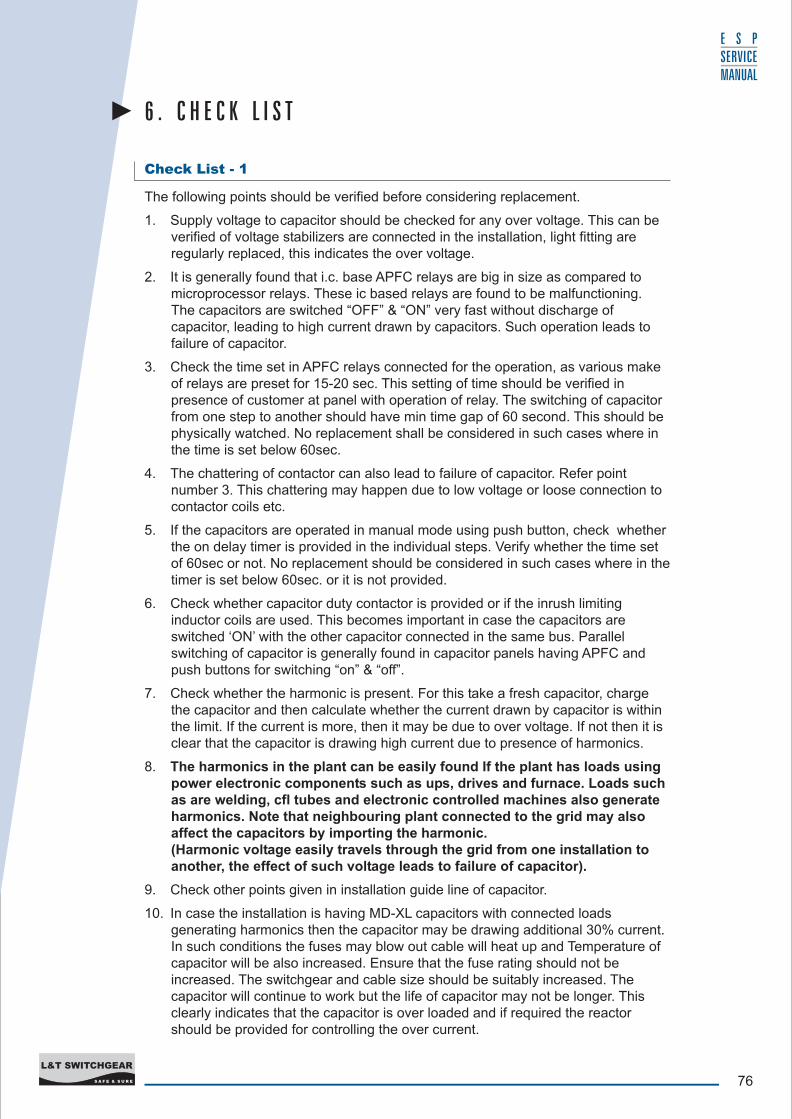
The following points should be verified before considering replacement.
1. Supply voltage to capacitor should be checked for any over voltage. This can be verified of voltage stabilizers are connected in the installation, light fitting are regularly replaced, this indicates the over voltage.
2. It is generally found that i.c. base APFC relays are big in size as compared to microprocessor relays. These ic based relays are found to be malfunctioning. The capacitors are switched “OFF” & “ON” very fast without discharge of capacitor, leading to high current drawn by capacitors. Such operation leads to failure of capacitor.
3. Check the time set in APFC relays connected for the operation, as various make of relays are preset for 15-20 sec. This setting of time should be verified in presence of customer at panel with operation of relay. The switching of capacitor from one step to another should have min time gap of 60 second. This should be physically watched. No replacement shall be considered in such cases where in the time is set below 60sec.
4. The chattering of contactor can also lead to failure of capacitor. Refer point number 3. This chattering may happen due to low voltage or loose connection to contactor coils etc.
5. If the capacitors are operated in manual mode using push button, check whether the on delay timer is provided in the individual steps. Verify whether the time set of 60sec or not. No replacement should be considered in such cases where in the timer is set below 60sec. or it is not provided.
6. Check whether capacitor duty contactor is provided or if the inrush limiting inductor coils are used. This becomes important in case the capacitors are switched ‘ON’ with the other capacitor connected in the same bus. Parallel switching of capacitor is generally found in capacitor panels having APFC and push buttons for switching “on” & “off”.
7. Check whether the harmonic is present. For this take a fresh capacitor, charge the capacitor and then calculate whether the current drawn by capacitor is within the limit. If the current is more, then it may be due to over voltage. If not then it is clear that the capacitor is drawing high current due to presence of harmonics.
8. The harmonics in the plant can be easily found If the plant has loads using power electronic components such as ups, drives and furnace. Loads such as are welding, cfl tubes and electronic controlled machines also generate harmonics. Note that neighbouring plant connected to the grid may also affect the capacitors by importing the harmonic. (Harmonic voltage easily travels through the grid from one installation to another, the effect of such voltage leads to failure of capacitor).
9. Check other points given in installation guide line of capacitor.
10. In case the installation is having MD-XL capacitors with connected loads generating harmonics then the capacitor may be drawing additional 30% current. In such conditions the fuses may blow out cable will heat up and Temperature of capacitor will be also increased. Ensure that the fuse rating should not be increased. The switchgear and cable size should be suitably increased. The capacitor will continue to work but the life of capacitor may not be longer. This clearly indicates that the capacitor is over loaded and if required the reactor should be provided for controlling the over current.
6 . C H E C K L I S T
77S A F E & S U R E
L&T SWITCHGEAR
E S P SERVICE MANUAL
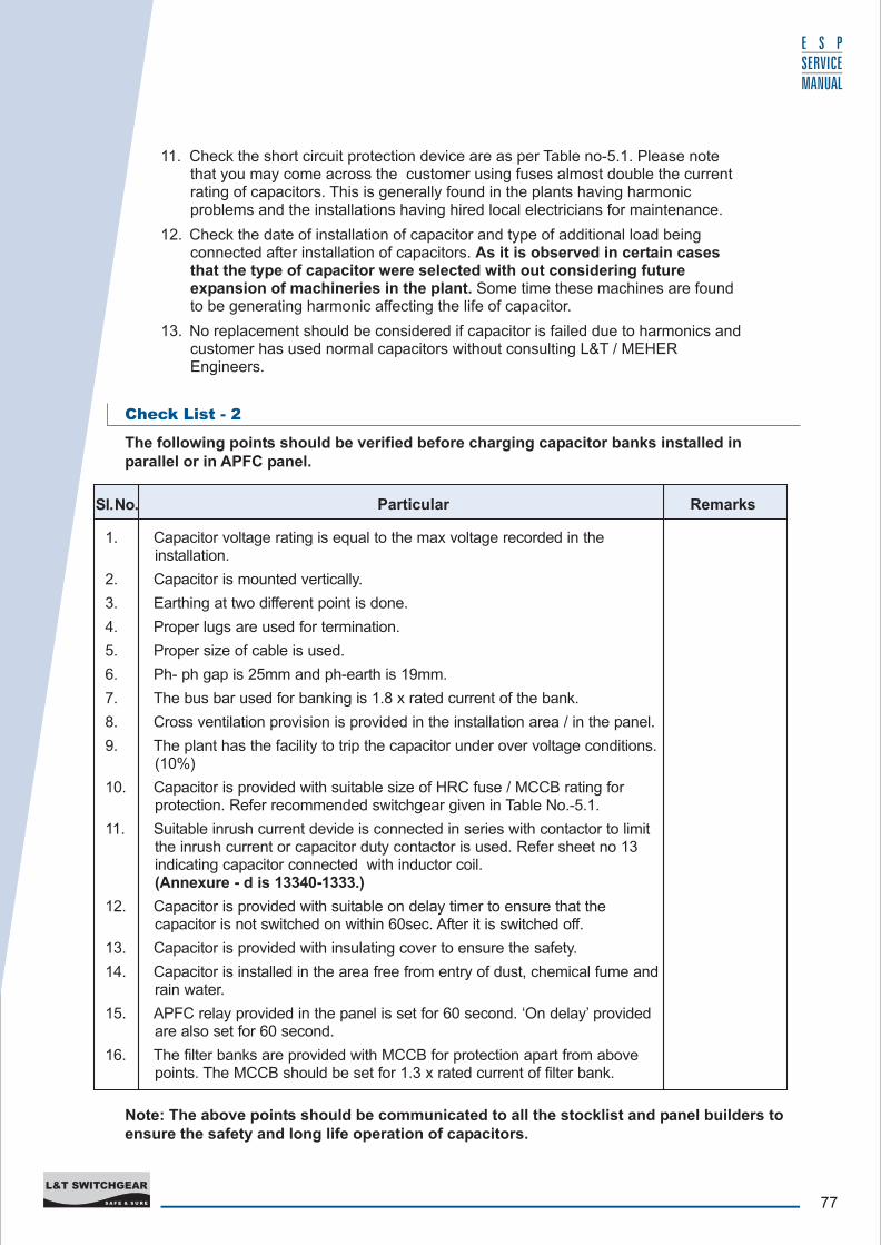
11. Check the short circuit protection device are as per Table no-5.1. Please note that you may come across the customer using fuses almost double the current rating of capacitors. This is generally found in the plants having harmonic problems and the installations having hired local electricians for maintenance.
12. Check the date of installation of capacitor and type of additional load being connected after installation of capacitors. As it is observed in certain cases that the type of capacitor were selected with out considering future expansion of machineries in the plant. Some time these machines are found to be generating harmonic affecting the life of capacitor.
13. No replacement should be considered if capacitor is failed due to harmonics and customer has used normal capacitors without consulting L&T / MEHER Engineers.
Check List - 2
The following points should be verified before charging capacitor banks installed in parallel or in APFC panel.
1. Capacitor voltage rating is equal to the max voltage recorded in the installation.
2. Capacitor is mounted vertically.
3. Earthing at two different point is done.
4. Proper lugs are used for termination.
5. Proper size of cable is used.
6. Ph- ph gap is 25mm and ph-earth is 19mm.
7. The bus bar used for banking is 1.8 x rated current of the bank.
8. Cross ventilation provision is provided in the installation area / in the panel.
9. The plant has the facility to trip the capacitor under over voltage conditions. (10%)
10. Capacitor is provided with suitable size of HRC fuse / MCCB rating for protection. Refer recommended switchgear given in Table No.-5.1.
11. Suitable inrush current devide is connected in series with contactor to limit the inrush current or capacitor duty contactor is used. Refer sheet no 13 indicating capacitor connected with inductor coil. (Annexure - d is 13340-1333.)
12. Capacitor is provided with suitable on delay timer to ensure that the capacitor is not switched on within 60sec. After it is switched off.
13. Capacitor is provided with insulating cover to ensure the safety.
14. Capacitor is installed in the area free from entry of dust, chemical fume and rain water.
15. APFC relay provided in the panel is set for 60 second. ‘On delay’ provided are also set for 60 second.
16. The filter banks are provided with MCCB for protection apart from above points. The MCCB should be set for 1.3 x rated current of filter bank.
Sl. No. Particular Remarks
Note: The above points should be communicated to all the stocklist and panel builders to ensure the safety and long life operation of capacitors.
78S A F E & S U R E
L&T SWITCHGEAR
E S P SERVICE MANUAL
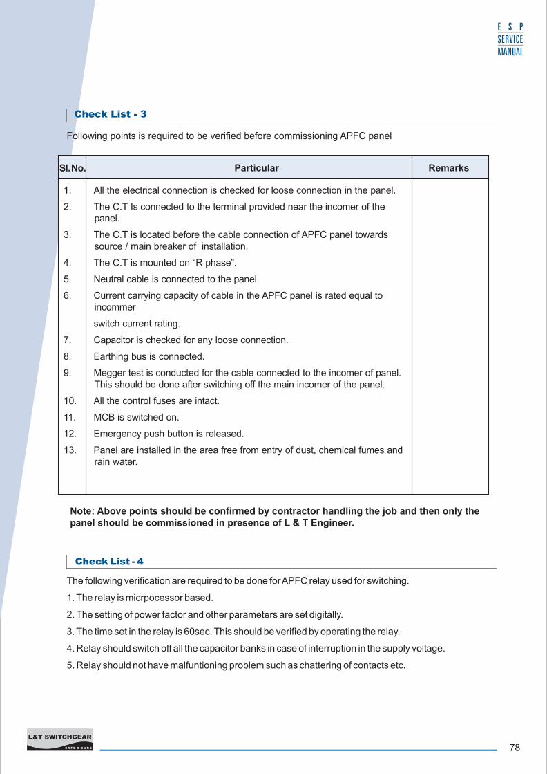
Check List - 4
The following verification are required to be done for APFC relay used for switching.
1. The relay is micrpocessor based.
2. The setting of power factor and other parameters are set digitally.
3. The time set in the relay is 60sec. This should be verified by operating the relay.
4. Relay should switch off all the capacitor banks in case of interruption in the supply voltage.
5. Relay should not have malfuntioning problem such as chattering of contacts etc.
Note: Above points should be confirmed by contractor handling the job and then only the panel should be commissioned in presence of L & T Engineer.
Check List - 3
Following points is required to be verified before commissioning APFC panel
Sl. No. Particular Remarks
1. All the electrical connection is checked for loose connection in the panel.
2. The C.T Is connected to the terminal provided near the incomer of the panel.
3. The C.T is located before the cable connection of APFC panel towards source / main breaker of installation.
4. The C.T is mounted on “R phase”.
5. Neutral cable is connected to the panel.
6. Current carrying capacity of cable in the APFC panel is rated equal to incommer
switch current rating.
7. Capacitor is checked for any loose connection.
8. Earthing bus is connected.
9. Megger test is conducted for the cable connected to the incomer of panel. This should be done after switching off the main incomer of the panel.
10. All the control fuses are intact.
11. MCB is switched on.
12. Emergency push button is released.
13. Panel are installed in the area free from entry of dust, chemical fumes and rain water.
79S A F E & S U R E
L&T SWITCHGEAR
E S P SERVICE MANUAL
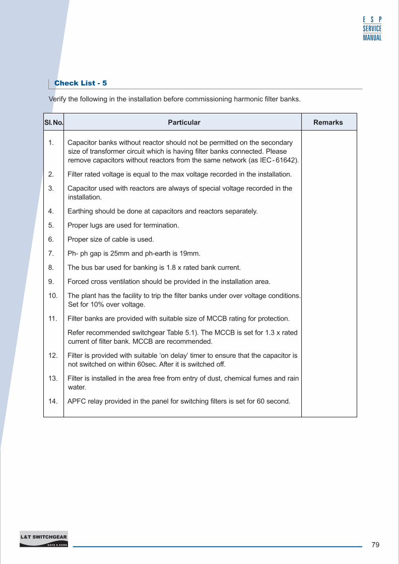
Verify the following in the installation before commissioning harmonic filter banks.
1. Capacitor banks without reactor should not be permitted on the secondary size of transformer circuit which is having filter banks connected. Please
remove capacitors without reactors from the same network (as IEC- 61642).
2. Filter rated voltage is equal to the max voltage recorded in the installation.
3. Capacitor used with reactors are always of special voltage recorded in the installation.
4. Earthing should be done at capacitors and reactors separately.
5. Proper lugs are used for termination.
6. Proper size of cable is used.
7. Ph- ph gap is 25mm and ph-earth is 19mm.
8. The bus bar used for banking is 1.8 x rated bank current.
9. Forced cross ventilation should be provided in the installation area.
10. The plant has the facility to trip the filter banks under over voltage conditions. Set for 10% over voltage.
11. Filter banks are provided with suitable size of MCCB rating for protection.
Refer recommended switchgear Table 5.1). The MCCB is set for 1.3 x rated current of filter bank. MCCB are recommended.
12. Filter is provided with suitable ‘on delay’ timer to ensure that the capacitor is
not switched on within 60sec. After it is switched off.
13. Filter is installed in the area free from entry of dust, chemical fumes and rain water.
14. APFC relay provided in the panel for switching filters is set for 60 second.
Sl. No. Particular Remarks
Check List - 5

80S A F E & S U R E
L&T SWITCHGEAR
E S P SERVICE MANUAL
Caution :
1. The site should be free from excessive dust, chemical fumes & vibrations as the fumes and vibrations will lead to damage of electrical contacts.
2. Ensure that all the electrical connection in the panel are tight, as any loose
connection will lead to increase in temperature and short circuit.
3. Ensure that APFC panel is installed with capacitors suitable for your electrical network. As loads such as Arc furnace, Welding, Battery Charges, UPS, Power Electronics for motor controls (AC/DC Drivers) and
Telecommunication equipment generates harmonics which may lead to failure of normal capacitor.
1. Shift the panel to the location where it is required to be installed.
(a) Position the panel on the foundation and lock the panel base frame with the foundation bolts for free standing panels, by using spirit level and plumber
block for achieving horizontal and vertical leveling.
(b) Position panel of the wall / structure and fix with wall mounting brackets
provided along with the panel. Leveling should be done here also as explained above.
2. Connect the earth conductor to the panel terminal provided on either side of the
panel.
3. Use the key provided to open the door of the panel make sure that electrical
connection of all equipments are intact. This is particularly important since vibration in transportation sometimes may have resulted inloose connections.
4. Using a star screw driver, open the rear door of the free standing panel. Make two
number suitable cut outs for 3.5 core power cable and 2 core 2. Sq mm cooper multi stand C.T control cable in the gland plate provided. . Using suitable size of
cable gland connect the cables. Ensure that the cable gland is fixed properly
without any gaps in the gland plate for proper sealing of the opening to prevent any entry of vermins.
5. The cable rated for current capacity equivalent to main incommer of panel should
be used. Use suitable size lugs for connecting the power cables.
6. Connect the cable to the terminals provided for the power supply. Make sure that
the correct phase identification is maintained while connection to the incoming terminals to the panel with respect to phases of supply line. As any mistake will
lead to the malfunctioning of relay.
7. Connect the ‘R’ phase C.T cable to the terminals provided. Refer Fig. Number 1 for power connection and C.T location.
8. The relay is pre-set for a secondary current output of 5A. In case the C.T secondary is 1 Amps then change
the dip switch provided behind on the front facia of the relay. (Refer the
printed information given on rear side of the relay.)
MEHER
7 . I N S T A L L A T I O N G U I D E L I N E S F O R A P F C P A N E L
81S A F E & S U R E
L&T SWITCHGEAR
E S P SERVICE MANUAL
1. Switch on the three-phase power supply to the panel. All the 3 phase indicating lamp will glow this indicates that the supply is available at the incoming terminals of the system. Now switch on the main incommer of the APFC system.
2. When the main incommer of system is closed the relay start flashing the
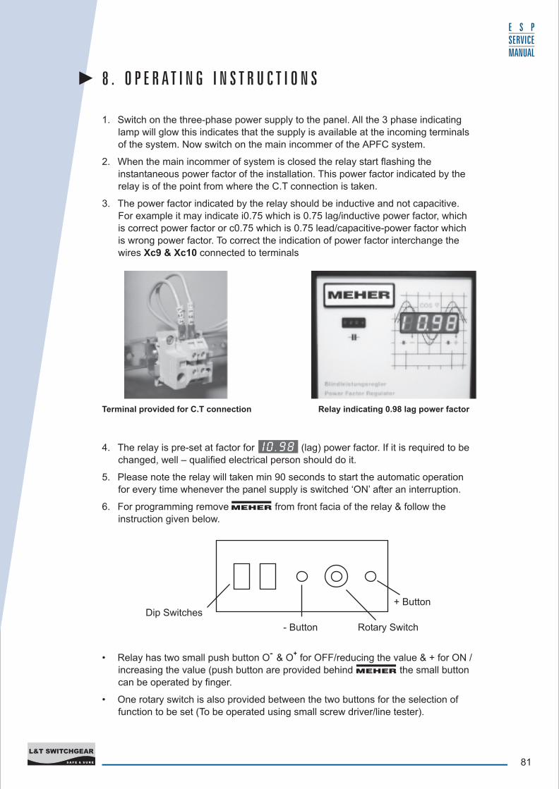
instantaneous power factor of the installation. This power factor indicated by the relay is of the point from where the C.T connection is taken.
3. The power factor indicated by the relay should be inductive and not capacitive.
For example it may indicate i0.75 which is 0.75 lag/inductive power factor, which is correct power factor or c0.75 which is 0.75 lead/capacitive-power factor which
is wrong power factor. To correct the indication of power factor interchange the
wires Xc9 & Xc10 connected to terminals
8 . O P E R A T I N G I N S T R U C T I O N S
Dip Switches
- Button Rotary Switch
+ Button
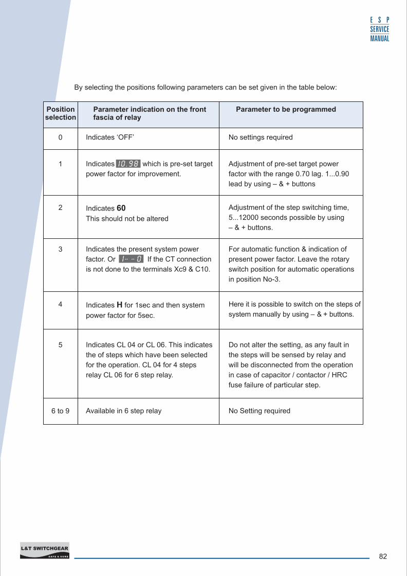
4. The relay is pre-set at factor for (lag) power factor. If it is required to be changed, well – qualified electrical person should do it.
5. Please note the relay will taken min 90 seconds to start the automatic operation
for every time whenever the panel supply is switched ‘ON’ after an interruption.
6. For programming remove from front facia of the relay & follow the instruction given below.
MEHER
-- +• Relay has two small push button O & O for OFF/reducing the value & + for ON /
increasing the value (push button are provided behind the small button
can be operated by finger.
• One rotary switch is also provided between the two buttons for the selection of
function to be set (To be operated using small screw driver/line tester).
MEHER
Relay indicating 0.98 lag power factorTerminal provided for C.T connection
82S A F E & S U R E
L&T SWITCHGEAR
E S P SERVICE MANUAL
By selecting the positions following parameters can be set given in the table below:
Indicates the present system power
factor. Or If the CT connection
is not done to the terminals Xc9 & C10.
Position selection
0
1
2
3
4
5
6 to 9
Parameter indication on the front fascia of relay
Indicates ‘OFF’
Indicates which is pre-set target
power factor for improvement.
Indicates 60
This should not be altered
Indicates H for 1sec and then system
power factor for 5sec.
Indicates CL 04 or CL 06. This indicates
the of steps which have been selected
for the operation. CL 04 for 4 steps
relay CL 06 for 6 step relay.
Available in 6 step relay
Parameter to be programmed
No settings required
Adjustment of pre-set target power
factor with the range 0.70 lag. 1...0.90
lead by using – & + buttons
Adjustment of the step switching time,
5...12000 seconds possible by using
– & + buttons.
For automatic function & indication of
present power factor. Leave the rotary
switch position for automatic operations
in position No-3.
Here it is possible to switch on the steps of
system manually by using – & + buttons.
Do not alter the setting, as any fault in
the steps will be sensed by relay and
will be disconnected from the operation
in case of capacitor / contactor / HRC
fuse failure of particular step.
No Setting required
83S A F E & S U R E
L&T SWITCHGEAR
E S P SERVICE MANUAL
T – Relay is not functioning
R – Check the CT and Voltage connection are done as per above given instructions.
Check the voltage across terminal A, L2 & L3 of relay (it should be 415 / 440 volts).
T – Contactor is not operating
R – Check the contractor coils and fuse connected to the terminal A of the relay. Also
check the fuse provided for individual contactor protection.
T – Contactor are operating but it is not holding (AL display)
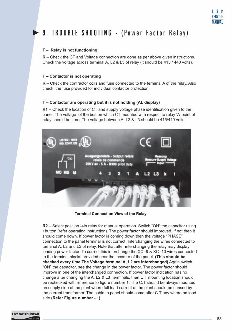
R1 – Check the location of CT and supply voltage phase identification given to the
panel. The voltage of the bus on which CT mounted with respect to relay ‘A’ point of relay should be zero. The voltage between A, L2 & L3 should be 415/440 volts.
Terminal Connection View of the Relay
9 . T R O U B L E S H O O T I N G - ( P o w e r F a c t o r R e l a y )
R2 – Select position -4in relay for manual operation. Switch “ON” the capacitor using
+button (refer operating instruction). The power factor should improved. If not then it should come down. If power factor is coming down then the voltage “PHASE”
connection to the panel terminal is not correct. Interchanging the wires connected to terminal A, L2 and L3 of relay. Note that after interchanging the relay may display
leading power factor. To correct this interchange the XC -9 & XC -10 wires connected
to the terminal blocks provided near the incomer of the panel. (This should be checked every time The Voltage terminal A, L2 are Interchanged) Again switch
“ON” the capacitor, see the change in the power factor. The power factor should improve in one of the interchanged connection. If power factor indication has no change after changing the A, L2 & L3 terminals, then C.T mounting location should
be rechecked with reference to figure number 1. The C.T should be always mounted on supply side of the plant where full load current of the plant should be sensed by the current transformer. The cable to panel should come after C.T any where on load side (Refer Figure number - 1).
84S A F E & S U R E
L&T SWITCHGEAR
E S P SERVICE MANUAL
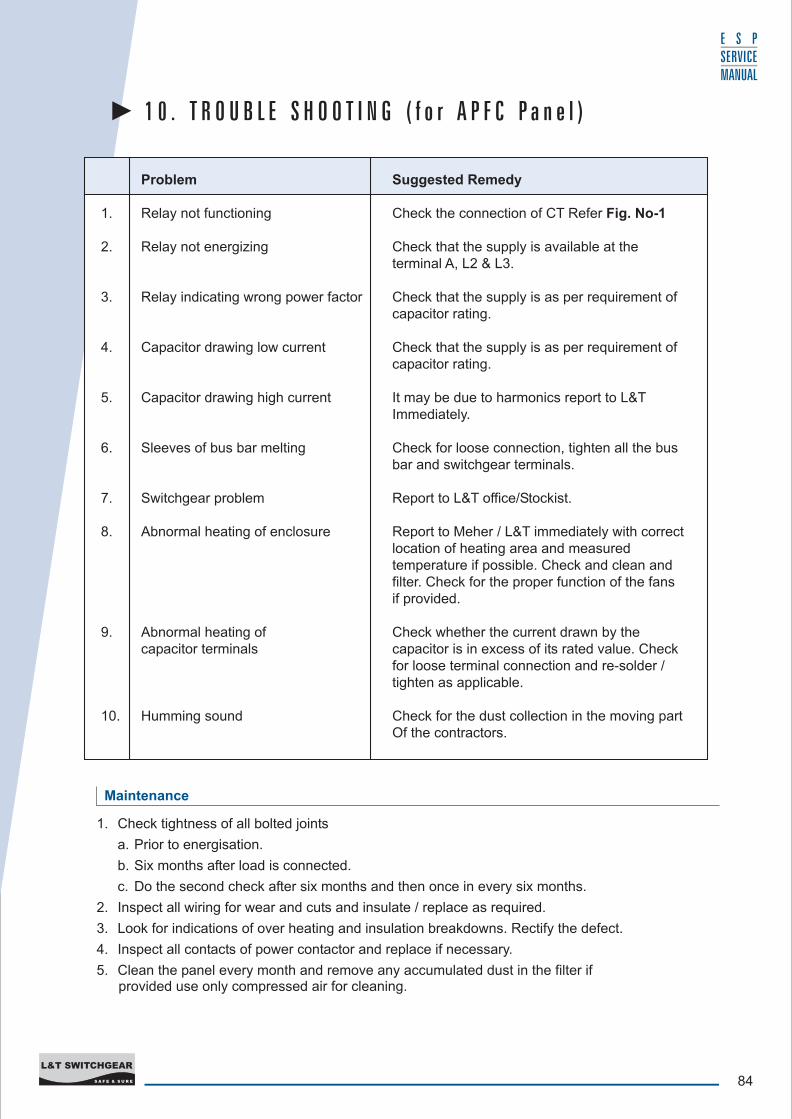
Problem Suggested Remedy
1. Relay not functioning Check the connection of CT Refer Fig. No-1
2. Relay not energizing Check that the supply is available at the terminal A, L2 & L3.
3. Relay indicating wrong power factor Check that the supply is as per requirement of capacitor rating.
4. Capacitor drawing low current Check that the supply is as per requirement of capacitor rating.
5. Capacitor drawing high current It may be due to harmonics report to L&T Immediately.
6. Sleeves of bus bar melting Check for loose connection, tighten all the bus bar and switchgear terminals.
7. Switchgear problem Report to L&T office/Stockist.
8. Abnormal heating of enclosure Report to Meher / L&T immediately with correct location of heating area and measured temperature if possible. Check and clean and filter. Check for the proper function of the fans if provided.
9. Abnormal heating of Check whether the current drawn by the capacitor terminals capacitor is in excess of its rated value. Check
for loose terminal connection and re-solder / tighten as applicable.
10. Humming sound Check for the dust collection in the moving part Of the contractors.
1 0 . T R O U B L E S H O O T I N G ( f o r A P F C P a n e l )
Maintenance
1. Check tightness of all bolted joints
a. Prior to energisation.
b. Six months after load is connected.
c. Do the second check after six months and then once in every six months.
2. Inspect all wiring for wear and cuts and insulate / replace as required.
3. Look for indications of over heating and insulation breakdowns. Rectify the defect.
4. Inspect all contacts of power contactor and replace if necessary.
5. Clean the panel every month and remove any accumulated dust in the filter if provided use only compressed air for cleaning.