CAP 413 Radiotelephony Manual - Anglian Flight Centres
206
CAP 413 Radiotelephony Manual Edition 17 www.caa.co.uk Safety Regulation Group
Transcript of CAP 413 Radiotelephony Manual - Anglian Flight Centres
CAP 413
Radiotelephony Manual
Edition 17
www.caa.co.uk
Safety Regulation Group


CAP 413
Radiotelephony Manual
Edition 17
Safety Regulation Group
21 July 2008
CAP 413 Radiotelephony Manual
© Civil Aviation Authority 2008
All rights reserved. Copies of this publication may be reproduced for personal use, or for use within acompany or organisation, but may not otherwise be reproduced for publication.
To use or reference CAA publications for any other purpose, for example within training material forstudents, please contact the CAA at the address below for formal agreement.
ISBN 978 0 11790 964 9
First published September 1978Second edition April 1984Third edition August 1992Fourth edition January 1994Fifth edition January 1995Sixth edition January 1996Seventh edition December 1996Eighth edition January 1998Ninth edition January 1999Tenth edition January 2000Eleventh edition January 2001Twelfth edition 5 February 2002 (corrected 7 February 2002)Thirteenth edition 1 October 2002Fourteenth edition 1 September 2003Fifteenth edition 1 September 2004Sixteenth edition 1 May 2006Seventeenth edition 21 July 2008
Enquiries regarding the content of this publication should be addressed to:Air Traffic Standards Division, Safety Regulation Group, Civil Aviation Authority, Aviation House, GatwickAirport South, West Sussex, RH6 0YR
The latest version of this document and all applicable amendments are available in electronic format atwww.caa.co.uk/publications, where you may also register for e-mail notification of amendments.
Published by TSO (The Stationery Office) on behalf of the UK Civil Aviation Authority.
Printed copy available from: TSO, PO Box 29, Norwich NR3 1GN www.tso.co.uk/bookshopTelephone orders/General enquiries: 0870 600 5522 E-mail: [email protected] orders: 0870 600 5533 Textphone: 0870 240 3701

CAP 413 Radiotelephony Manual
Chapter Page Date Chapter Page Date
List of Effective Pages
iii 21 July 2008
iv 21 July 2008
v 21 July 2008
Contents 1 21 July 2008
Contents 2 21 July 2008
Contents 3 21 July 2008
Contents 4 21 July 2008
Contents 5 21 July 2008
Contents 6 21 July 2008
Revision History 1 21 July 2008
Revision History 2 21 July 2008
Revision History 3 21 July 2008
Revision History 4 21 July 2008
Revision History 5 21 July 2008
Foreword 1 21 July 2008
Foreword 2 21 July 2008
Chapter 1 1 21 July 2008
Chapter 1 2 21 July 2008
Chapter 1 3 21 July 2008
Chapter 1 4 21 July 2008
Chapter 1 5 21 July 2008
Chapter 1 6 21 July 2008
Chapter 1 7 21 July 2008
Chapter 1 8 21 July 2008
Chapter 1 9 21 July 2008
Chapter 2 1 21 July 2008
Chapter 2 2 21 July 2008
Chapter 2 3 21 July 2008
Chapter 2 4 21 July 2008
Chapter 2 5 21 July 2008
Chapter 2 6 21 July 2008
Chapter 2 7 21 July 2008
Chapter 2 8 21 July 2008
Chapter 2 9 21 July 2008
Chapter 2 10 21 July 2008
Chapter 2 11 21 July 2008
Chapter 2 12 21 July 2008
Chapter 2 13 21 July 2008
Chapter 2 14 21 July 2008
Chapter 2 15 21 July 2008
Chapter 2 16 21 July 2008
Chapter 2 17 21 July 2008
Chapter 2 18 21 July 2008
Chapter 3 1 21 July 2008
Chapter 3 2 21 July 2008
Chapter 3 3 21 July 2008
Chapter 3 4 21 July 2008
Chapter 3 5 21 July 2008
Chapter 3 6 21 July 2008
Chapter 3 7 21 July 2008
Chapter 3 8 21 July 2008
Chapter 4 1 21 July 2008
Chapter 4 2 21 July 2008
Chapter 4 3 21 July 2008
Chapter 4 4 21 July 2008
Chapter 4 5 21 July 2008
Chapter 4 6 21 July 2008
Chapter 4 7 21 July 2008
Chapter 4 8 21 July 2008
Chapter 4 9 21 July 2008
Chapter 4 10 21 July 2008
Chapter 4 11 21 July 2008
Chapter 4 12 21 July 2008
Chapter 4 13 21 July 2008
Chapter 4 14 21 July 2008
Chapter 4 15 21 July 2008
Chapter 4 16 21 July 2008
Chapter 4 17 21 July 2008
Chapter 4 18 21 July 2008
Chapter 4 19 21 July 2008
Chapter 4 20 21 July 2008
Chapter 4 21 21 July 2008
Chapter 4 22 21 July 2008
Chapter 4 23 21 July 2008
Chapter 4 24 21 July 2008
Chapter 4 25 21 July 2008
Chapter 4 26 21 July 2008
Chapter 4 27 21 July 2008
Chapter 4 28 21 July 2008
Chapter 4 29 21 July 2008
Chapter 4 30 21 July 2008
Chapter 4 31 21 July 2008
Chapter 4 32 21 July 2008
Chapter 4 33 21 July 2008
Chapter 4 34 21 July 2008
Chapter 4 35 21 July 2008
Chapter 4 36 21 July 2008
Chapter 4 37 21 July 2008
Page iii21 July 2008

CAP 413 Radiotelephony Manual
Chapter Page Date Chapter Page Date
Chapter 4 38 21 July 2008
Chapter 4 39 21 July 2008
Chapter 4 40 21 July 2008
Chapter 5 1 21 July 2008
Chapter 5 2 21 July 2008
Chapter 5 3 21 July 2008
Chapter 5 4 21 July 2008
Chapter 5 5 21 July 2008
Chapter 5 6 21 July 2008
Chapter 5 7 21 July 2008
Chapter 5 8 21 July 2008
Chapter 5 9 21 July 2008
Chapter 6 1 21 July 2008
Chapter 6 2 21 July 2008
Chapter 6 3 21 July 2008
Chapter 6 4 21 July 2008
Chapter 6 5 21 July 2008
Chapter 6 6 21 July 2008
Chapter 6 7 21 July 2008
Chapter 6 8 21 July 2008
Chapter 6 9 21 July 2008
Chapter 6 10 21 July 2008
Chapter 6 11 21 July 2008
Chapter 6 12 21 July 2008
Chapter 6 13 21 July 2008
Chapter 6 14 21 July 2008
Chapter 6 15 21 July 2008
Chapter 6 16 21 July 2008
Chapter 6 17 21 July 2008
Chapter 6 18 21 July 2008
Chapter 6 19 21 July 2008
Chapter 6 20 21 July 2008
Chapter 6 21 21 July 2008
Chapter 6 22 21 July 2008
Chapter 6 23 21 July 2008
Chapter 6 24 21 July 2008
Chapter 6 25 21 July 2008
Chapter 6 26 21 July 2008
Chapter 6 27 21 July 2008
Chapter 7 1 21 July 2008
Chapter 7 2 21 July 2008
Chapter 7 3 21 July 2008
Chapter 7 4 21 July 2008
Chapter 7 5 21 July 2008
Chapter 8 1 21 July 2008
Chapter 8 2 21 July 2008
Chapter 8 3 21 July 2008
Chapter 8 4 21 July 2008
Chapter 8 5 21 July 2008
Chapter 8 6 21 July 2008
Chapter 9 1 21 July 2008
Chapter 9 2 21 July 2008
Chapter 9 3 21 July 2008
Chapter 9 4 21 July 2008
Chapter 9 5 21 July 2008
Chapter 9 6 21 July 2008
Chapter 10 1 21 July 2008
Chapter 10 2 21 July 2008
Chapter 10 3 21 July 2008
Chapter 10 4 21 July 2008
Chapter 10 5 21 July 2008
Chapter 10 6 21 July 2008
Chapter 10 7 21 July 2008
Chapter 10 8 21 July 2008
Chapter 10 9 21 July 2008
Chapter 10 10 21 July 2008
Chapter 10 11 21 July 2008
Chapter 10 12 21 July 2008
Chapter 10 13 21 July 2008
Chapter 10 14 21 July 2008
Chapter 10 15 21 July 2008
Chapter 10 16 21 July 2008
Chapter 10 17 21 July 2008
Chapter 10 18 21 July 2008
Chapter 10 19 21 July 2008
Chapter 10 20 21 July 2008
Chapter 10 21 21 July 2008
Chapter 10 22 21 July 2008
Chapter 10 23 21 July 2008
Chapter 10 24 21 July 2008
Chapter 10 25 21 July 2008
Chapter 10 26 21 July 2008
Chapter 10 27 21 July 2008
Chapter 10 28 21 July 2008
Chapter 10 29 21 July 2008
Chapter 10 30 21 July 2008
Chapter 10 31 21 July 2008
Chapter 10 32 21 July 2008
Chapter 10 33 21 July 2008
Chapter 10 34 21 July 2008
Chapter 10 35 21 July 2008
Chapter 10 36 21 July 2008
Page iv21 July 2008

CAP 413 Radiotelephony Manual
Chapter Page Date Chapter Page Date
Chapter 10 37 21 July 2008
Chapter 10 38 21 July 2008
Appendix 1 1 21 July 2008
Appendix 1 2 21 July 2008
Appendix 1 3 21 July 2008
Bibliography 1 21 July 2008
Index 1 21 July 2008
Index 2 21 July 2008
Index 3 21 July 2008
Index 4 21 July 2008
Index 5 21 July 2008
Index 6 21 July 2008
Index 7 21 July 2008
Page v21 July 2008

INTENTIONALLY LEFT BLANK
CAP 413 Radiotelephony Manual
Contents
List of Effective Pages iii
Revision History 1
Foreword 1
Document Description 1
Document Purpose 1
Document Applicability 1
Document Source 1
Document Format 1
Document Revisions 2
Document Availability 2
Document Comments and Queries 2
Chapter 1 Glossary
Terms 1
Definitions 1
Abbreviations 4
Chapter 2 Radiotelephony
General Procedures 1
Introduction 1
Transmitting Technique 1
Transmission of Letters 2
Transmission of Numbers 3
Transmission of Time 4
Standard Words and Phrases 5
Callsigns for Aeronautical Stations 7
Callsigns for Aircraft 8
Continuation of Communications 9
Corrections and Repetitions 10
Acknowledgement of Receipt 11
Transfer of Communications 11
Contents Page 121 July 2008

CAP 413 Radiotelephony Manual
Clearance Issue and Read Back Requirements 11
Simultaneous Transmissions 14
Complying with Clearances and Instructions 14
Communication Failure 15
Test Transmissions 16
Pilot Complaints Concerning Aeronautical Telecommunications 17
Air Traffic Service Complaints ConcerningAircraft Communications 17
Hours of Service and Communications Watch 17
Record of Communications 17
Categories of Message 18
Chapter 3 General Phraseology
General 1
Introduction 1
Level Reporting 1
Initial Call - IFR flights 4
Initial Call - VFR Flight 5
Reply to 'Pass Your Message' 6
Position Reporting 7
Flight Plans 7
Chapter 4 Aerodrome Phraseology
Aerodrome Control Service Phraseology 1
Introduction 1
Type of Service 1
Departure Information and Engine Starting Procedures 1
Pushback and Powerback 2
Taxi Instructions 2
Pre-Departure Manoeuvring 4
Take-Off Clearance 5
Aerodrome Traffic Circuit 8
Final Approach and Landing 11
Missed Approach 13
Runway Vacating and Communicating After Landing 13
Essential Aerodrome Information 14
Contents Page 221 July 2008

CAP 413 Radiotelephony Manual
Aerodrome Flight Information Service Phraseology 15
Introduction 15
Type of Service 15
AFIS Phraseology for Ground Movement, Take-off, Landingand Transit 16
Aerodrome Phraseology for Helicopters 20
Introduction 20
Helicopter Callsigns 20
Helicopter Phraseology for Taxiing 20
Helicopter Phraseology for Take-Off and Landing (ATC Only) 21
Helicopter Taxiing Phraseology Examples (ATC and AFIS Only) 22
Helicopter Take-Off and Landing PhraseologyExamples (ATC only) 22
Aerodrome Phraseology for Vehicles (ATC and AFIS only) 24
Introduction 24
Movement Instructions 24
To Cross a Runway 25
Vehicles Towing Aircraft 26
Aerodrome Air/Ground Communication Service Phraseology 27
Introduction 27
Type of Service 27
Air/Ground Station Identification 27
Phraseology and Examples 27
Offshore Communication Service 30
Radiotelephony Reports at Unattended Aerodromes 34
Introduction 34
Additional Procedures for the Use of SAFETYCOM 34
Unattended Aerodrome Phraseology Examples 35
Aerodrome Information 37
Meteorological Conditions 37
Voice Weather Broadcast (VOLMET) UK 37
Runway Visual Range (RVR)/Visibility/Absolute Minimum 38
Runway Surface Conditions 38
Automatic Terminal Information Service (ATIS) UK 40
Contents Page 321 July 2008

CAP 413 Radiotelephony Manual
Chapter 5 Radar Phraseology
General 1
Introduction 1
Radar Identification of Aircraft 1
Secondary Surveillance Radar Phraseology 2
Radar Service 4
Radar Vectoring 4
Traffic Information and Avoiding Action Phraseology 5
ACAS/TCAS Phraseology 6
Communications and Loss of Communications 7
Danger Area Crossing Service/Danger Area Activity Information Service 7
Chapter 6 Approach Phraseology
Approach Control Service Phraseology 1
IFR Departures 1
VFR Departures 2
IFR Arrivals 3
VFR Arrivals 6
Special VFR Flights 7
Vectoring to Final Approach 8
Direction Finding (DF) 11
VDF Procedure 11
NDB(L) and VOR Procedures 15
Area Navigation Global Navigation Satellite System RNAV (GNSS) Phraseology 17
Surveillance Radar Approach (SRA) 18
Landing Altimeter Setting (QNE) 21
PAR Approach 21
Military Aerodrome Traffic Zones (MATZ) and PenetrationServices 26
Lower Airspace Radar Service (LARS) 26
Chapter 7 Area Phraseology
Area Control Service Phraseology 1
General 1
Position Reporting 1
Contents Page 421 July 2008

CAP 413 Radiotelephony Manual
Flights Joining Airways 2
Flights Leaving Airways 2
Flights Crossing Airways 3
Flights Holding En-Route 3
Reduced Vertical Separation Minimum (RVSM) Phraseology 4
Chapter 8 Emergency Phraseology
Distress and Urgency Communication Procedures 1
Introduction 1
States of Emergency 1
VHF Emergency Service 1
VHF Emergency Service – General Procedures 2
Emergency Message 3
Speechless Code 4
Radio Procedures – Practice Emergencies 4
Training Fix 5
Relayed Emergency Message 5
Imposition of Silence 5
Termination of Distress Communications and of RTF Silence 6
Chapter 9 Miscellaneous Phraseology
Other Communications 1
Vortex Wake 1
Wind Shear 1
AIRPROX Reporting 1
Oil Pollution Reporting 2
Interceptions by Military Aircraft 2
Aircraft Operating Agency Messages 2
8.33 kHz Phraseology 3
Operations by aircraft deploying brake chutes 4
Chapter 10 Phraseology Examples
Examples of Types of Flights 1
Introduction 1
An IFR Flight 2
A VFR/IFR Flight 17
Flight in the Military Visual Circuit 25
Contents Page 521 July 2008

CAP 413 Radiotelephony Manual
Flight Receiving Lower Airspace Radar Service (LARS) andDanger Area Crossing Service (DACS) 29
Military Safety Broadcast - Securité 31
Callsign Prefix - ‘STUDENT’ 32
Flight Receiving Avoiding Action 33
Flight Receiving En-Route Flight Information Service 34
Flight Transmitting a Practice Pan 35
Arrival Flight (Aerodrome FIS) 37
Appendix 1 UK Differences to ICAO Radiotelephony Procedures
Bibliography 1
Index 1
Contents Page 621 July 2008
CAP 413 Radiotelephony Manual
Revision History
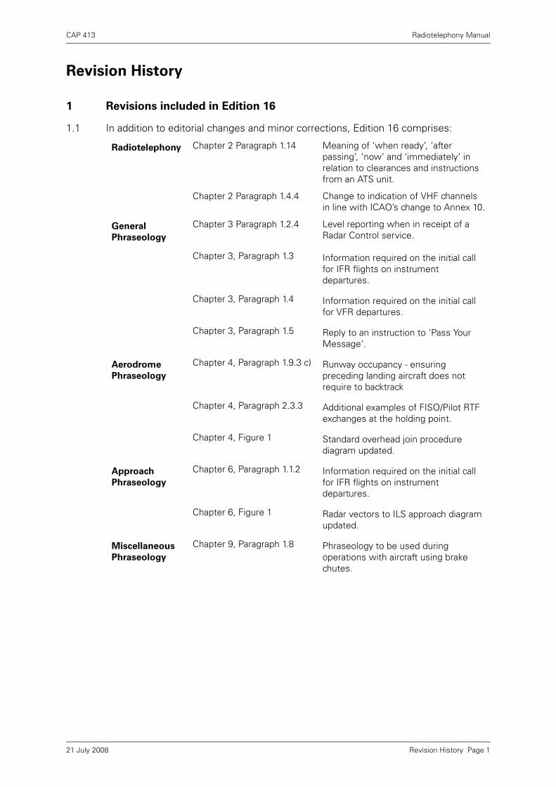
1 Revisions included in Edition 16
1.1 In addition to editorial changes and minor corrections, Edition 16 comprises:
Radiotelephony Chapter 2 Paragraph 1.14 Meaning of ‘when ready’, ‘after passing’, ‘now’ and ‘immediately’ in relation to clearances and instructions from an ATS unit.
Chapter 2 Paragraph 1.4.4 Change to indication of VHF channels in line with ICAO’s change to Annex 10.
General
Phraseology
Chapter 3 Paragraph 1.2.4 Level reporting when in receipt of a Radar Control service.
Chapter 3, Paragraph 1.3 Information required on the initial call for IFR flights on instrument departures.
Chapter 3, Paragraph 1.4 Information required on the initial call for VFR departures.
Chapter 3, Paragraph 1.5 Reply to an instruction to 'Pass Your Message'.
Aerodrome
Phraseology
Chapter 4, Paragraph 1.9.3 c) Runway occupancy - ensuring preceding landing aircraft does not require to backtrack
Chapter 4, Paragraph 2.3.3 Additional examples of FISO/Pilot RTF exchanges at the holding point.
Chapter 4, Figure 1 Standard overhead join procedure diagram updated.
Approach
Phraseology
Chapter 6, Paragraph 1.1.2 Information required on the initial call for IFR flights on instrument departures.
Chapter 6, Figure 1 Radar vectors to ILS approach diagram updated.
Miscellaneous
Phraseology
Chapter 9, Paragraph 1.8 Phraseology to be used during operations with aircraft using brake chutes.
Revision History Page 121 July 2008

CAP 413 Radiotelephony Manual
2 Revisions included in Edition 17
2.1 In addition to editorial changes and minor corrections, Edition 17 comprises:
Appendix 1 Table 1 Appendix 1 (Table of UK Differences to ICAO Radiotelephony Procedures)Cleared for ILS Approach is not used in the UK in order to prevent aircraft descending before establishing on the localiser. Instead pilots are asked to report established on the localiser; when established, descent instructions are given.Removal of difference concerning Holding Point and Holding Position. ICAO has now adopted the phraseology 'Holding Point' to remove potential for confusion with an instruction to 'Hold Position'.
Callsigns used
in examples
Throughout DocumentGlobal Change
Removes ‘Fastair’ (to prevent confusion with new ‘Fastjet/Fastprop’ prefix being introduced) and replaces ‘345’ with ‘347’ to conform with ICAO Doc 8585 and AIC 107/2000 guidance regarding use of potentially confusing numbers in callsigns).
Foreword Page 1 Change FIS to AFIS.
Abbreviations Chapter 1 Page 2 Delete FIS.
Abbreviations Chapter 1 Page 6 Delete FIS.
Callsigns Chapter 2 Page 7 Amend FISOs to read AFISOs.
Callsigns For
Aircraft
Chapter 2 Page 8 Adds content to initial call (removes impression that callsign alone is an acceptable form of initial call).
Callsigns For
Aircraft
Chapter 2 Page 8 Introduces ‘STUDENT’ callsign prefix and FASTJET/FASTPROP prefixes.
Simultaneous
transmissions
Chapter 2 Page 14 Inserts (as 1.14) additional text dealing with ‘blocked’ transmissions.
Level Reporting Chapter 3 Page 3 Introduces text regarding need to restrict rate of climb/descent to a maximum of 8000 ft/min when instructed to ‘expedite’.
Initial Call – IFR
Flights
Chapter 3 Page 4 and 5 Text dealing with level reporting amended to improve clarity.
Initial Call –
VFR Flights
Chapter 3 Page 5 Example amended from ‘request joining instructions’ to ‘request join’. Further example added to reflect a request for zone transit.
Revision History Page 221 July 2008

CAP 413 Radiotelephony Manual
Position
Reporting
Chapter 3 Page 7 Adds a GA example.
Designated
positions in the
Traffic circuit
Chapter 3 Page 8 Moves diagram and notes to more appropriate place in document (Chapter 4 Page 8).
Aerodrome
Phraseology
Chapter 4 Page 1 Amend FISOs to read AFISOs.
Taxi
Instructions
Chapter 4 Page 2 Add requirement for taxi clearances wherever possible to be noted down by pilots and removes ‘instructions’ from example.
Taxi
Instructions
Chapter 4 Page 2 and 3 Corrects example to reflect use of full aircraft callsign in ATC response to first call.
Taxi
Instructions
Chapter 4 Page 4 Inserts additional text dealing with optional insertion of ‘hold short of’ with taxi instructions which will involve a runway crossing.
Holding point
designator in
line-up
instruction
Chapter 4 Page 5 Makes provision for holding point designator to be included in any other line-up instruction when considered necessary.
Take-Off
Clearance
Chapter 4 Page 6andChapter 4 Page 7
Clarifies requirement to place the runway designator before the clearance.
Aerodrome
Traffic Circuit
Chapter 4 Page 8 Moves diagram and notes to more appropriate place in document.
Aerodrome
Traffic Circuit
Chapter 4 Page 9 Amends VFR arrival example to include earlier ‘request join’ call and response.
Final Approach
& Landing
Chapter 4 Page 11 Correction of typographical errors.
SAFETYCOM Chapter 4 Page 34 Removes anomaly regarding use of SAFETYCOM for ‘overhead ‘ call at 2000 ft above aerodrome.
Aerodrome FIS
Phraseology
Chapter 4 Page 15 Amendments which anticipate the introduction of revised ATSOCAS.
Aerodrome FIS
Phraseology
Chapter 4 Page 16 Amendments which anticipate the introduction of revised ATSOCAS.
Aerodrome FIS
Phraseology
Chapter 4 Page 17 Amendments which anticipate the introduction of revised ATSOCAS.
Aerodrome FIS
Phraseology
Chapter 4 Page 18 Amendments which anticipate the introduction of revised ATSOCAS.
Aerodrome FIS
Phraseology
Chapter 4 Page 24 Amendments which anticipate the introduction of revised ATSOCAS.
Revision History Page 321 July 2008

CAP 413 Radiotelephony Manual
Aerodrome
AGCS
Phraseology
Chapter 4 Page 27 Amendments which anticipate the introduction of revised ATSOCAS.
Aerodrome
AGCS
Phraseology
Chapter 4 Page 28 Amendments which anticipate the introduction of revised ATSOCAS.
Confirm (level) Chapter 5 Page 3 Removes explanatory text associated with the 200 ft tolerance used by controllers during Mode C checks. Change made to prevent inappropriate interpretation by pilots.
Traffic
Information
Chapter 5 Page 5 Editorial change to improve clarity.
Avoiding action
example
Chapter 5 Page 6 Includes example of avoiding action in the vertical plane and introduces term ‘unverified’.
ACAS/TCAS
Phraseology
Chapter 5 Page 6 Amends TCAS Phraseology to comply with change to ICAO SARPs (effective 22 Nov 07).
DACS/DAAIS Chapter 5 Page 8 Amendments which anticipate the introduction of revised ATSOCAS.
IFR Departures Chapter 6 Page 1 Introduces phraseology for requesting change to departure speed due to aircraft configuration.
IFR Arrivals Chapter 6 Page 3 Removes QFE from examples.
IFR Arrivals Chapter 6 Page 4 Removes QFE from examples.
IFR Arrivals Chapter 6 Page 5 Removes QFE from examples.
VFR Arrivals Chapter 6 Page 6 Amends example to include ‘request join’.
Special VFR
Flights
Chapter 6 Page 7 Corrects erroneous reference to 1500 ft rule (following legislative change).
Vectoring To
Final approach
Chapter 6 Page 9 Change in ILS phraseology.
Vectoring To
Final approach
Chapter 6 Page 10 Change in ILS phraseology.
Vectoring To
Final approach
Chapter 6 Page 13 Changes pressure setting used in the example from QFE to QNH.
Vectoring To
Final approach
Chapter 6 Page 14 Changes pressure setting used in the example from QFE to QNH.
Revision History Page 421 July 2008

CAP 413 Radiotelephony Manual
Vectoring To
Final approach
Chapter 6 Page 16 Changes pressure setting used in the example from QFE to QNH and removes sentence relating to normal use of QFE.
RNAV (GNSS)
Phraseology
Chapter 6 Page 17 Adds new phraseology section dealing with RNAV GNSS phraseology.
Surveillance
Radar
Approach
Chapter 6 Page 19 Changes ‘wheels’ to ‘gear’ and amends paragraph dealing with altimeter settings to reflect need for pilot to request QFE.
Surveillance
Radar
Approach
Chapter 6 Page 20 Reflects need to include Altitude and OCA when procedure is being conducted with reference to QNH.
LARS Chapter 6 Page 26 and 27 Deletions which anticipate the introduction of revised ATSOCAS.
MAYDAY and
PAN callsign
prefix
Chapter 8 Page 3 Permits ‘MAYDAY’ and ‘PAN’ to be used as a callsign prefix subsequent to the initial distress/urgency message at the discretion of pilots and controllers.
Emergency
Message
Chapter 8 Page 3 Removes reference to use of obsolete military prefix ‘TYRO’ and introduces use of callsign prefix ‘STUDENT’ with emergency message.
Limitations Chapter 9 Page 3 Amendments which anticipate the introduction of revised ATSOCAS.
Brake chutes Chapter 9 Page 5 Amendments which anticipate the introduction of revised ATSOCAS.
VFR-FIS
Request
Chapter 10 Page 20 Amendments which anticipate the introduction of revised ATSOCAS.
Phraseology
Examples
Chapter 10 Page 32 Includes examples of the use of the callsign prefix ‘STUDENT’.
Phraseology
Examples
Chapter 10 Page 37 Amends example of VFR arrival to include ‘request join’.
Joining
Information
Chapter 10 Page 38 Amendments which anticipate the introduction of revised ATSOCAS.
UK Differences
to ICAO
Appendix 1 Page 1 Delete 5th row of table dealing with ‘Go Ahead’. Replace with text dealing with ‘PAN PAN MEDICAL’.
UK Differences
to ICAO
Appendix 1 Page 2 Insert new row dealing with aircraft callsigns.
UK Differences
to ICAO RTF
Procedures
Appendix 1 Page 2 Updates wording relating to UK ILS phraseology differences.
Revision History Page 521 July 2008

INTENTIONALLY LEFT BLANK
CAP 413 Radiotelephony Manual
Foreword
1 Document Description
1.1 Document Purpose
1.1.1 The aim of the United Kingdom Radiotelephony Manual (CAP 413) is to provide pilotsand Air Traffic Services personnel with a compendium of clear, concise, standardisedphraseology and associated guidance, for radiotelephony communication in UnitedKingdom airspace.
1.2 Document Applicability
1.2.1 Radiotelephony (RTF) communications between United Kingdom air traffic servicesunits and pilots are expected to comply with the phraseology described in thismanual.
1.2.2 Operational details can be found in the United Kingdom Aeronautical InformationPublication (UK AIP). Phraseology for air traffic controllers (consistent with CAP 413)is also published in the Manual of Air Traffic Services (CAP 493).
1.2.3 CAP 413 is also a useful reference for those studying for the UK FlightRadiotelephony Operator's Licence.
1.2.4 Candidates for JAA pilot and instrument rating examinations should note that thesyllabus for the communications examination is drawn directly from the InternationalCivil Aviation Organisation (ICAO) Annex 10 Volume 2 and ICAO Doc 9432-AN/925and not CAP 413.
1.3 Document Source
1.3.1 The UK RTF Manual is based on ICAO Annex 10 Volume 2 (CommunicationsProcedures) to the Convention on International Civil Aviation and ICAO PANS-ATM(Procedures for Air Navigation Services - Air Traffic Management) Doc. 4444.
1.3.2 Where the ICAO standard phraseology may be misunderstood, or has weaknesses inthe UK environment, different phraseology has been specified (and notified to ICAO).Significant differences between the ICAO standard phraseology and that specified foruse in CAP 413 are described in Appendix 1 to this publication.
1.4 Document Format
1.4.1 Examples of phraseology in CAP 413 are intended to be representative ofcommunications in common use. The initial call in a series of messages is shown onthe left side of the page; subsequent messages appear in chronological order on theright side of the page.
1.4.2 Black text and grey-scale illustrations are used to facilitate printing on monochromeprinters.
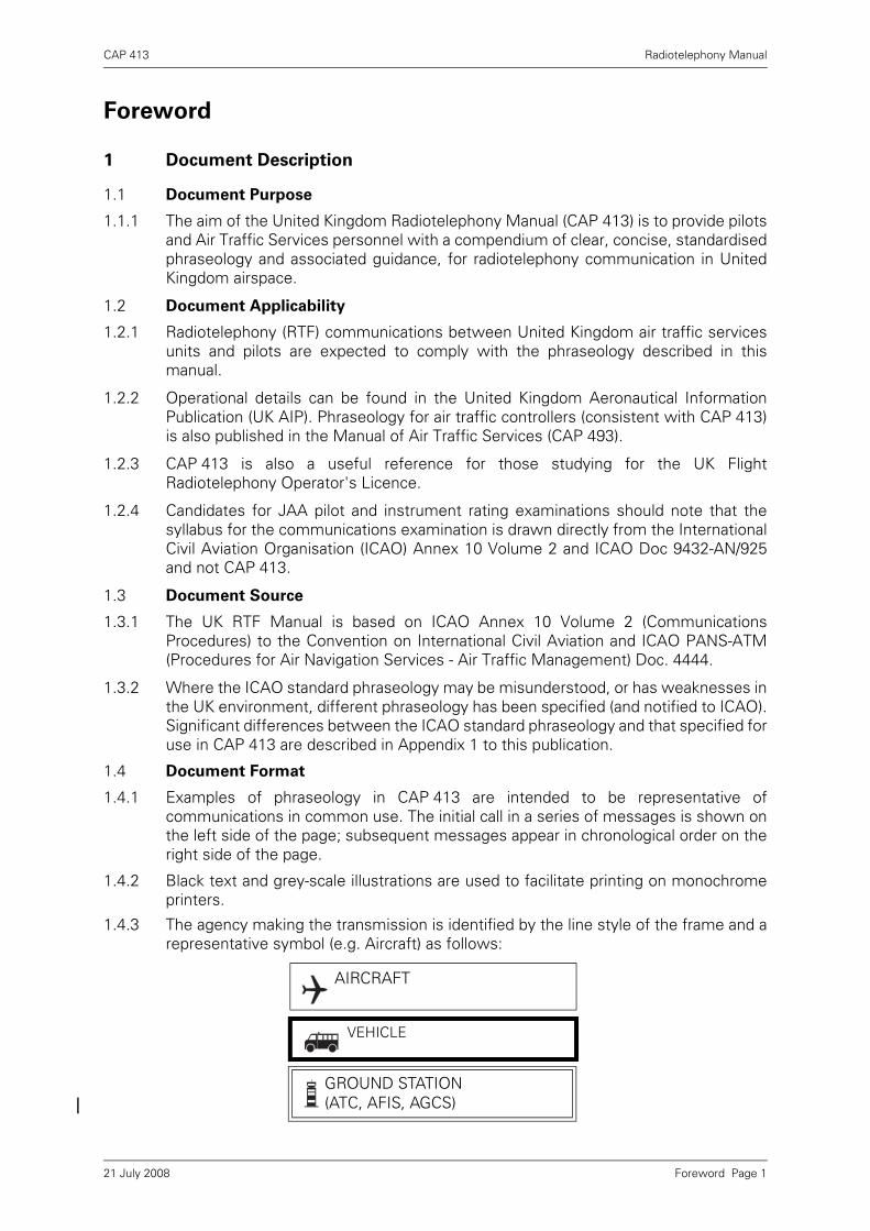
1.4.3 The agency making the transmission is identified by the line style of the frame and arepresentative symbol (e.g. Aircraft) as follows:
AIRCRAFT
VEHICLE
GROUND STATION (ATC, AFIS, AGCS)
Foreword Page 121 July 2008

CAP 413 Radiotelephony Manual
1.4.4 In this document the following protocol is used:
a) The words 'must' or 'shall' indicate that compliance is compulsory.
b) The word 'should' indicates a recommendation.
c) The word 'may' indicates an option.
d) The word 'will' is used to express the future.
1.4.5 Any reference in this document to the male gender should be understood to includeboth male and female persons.
1.5 Document Revisions
1.5.1 Major changes to RTF phraseology are notified by issuing an Aeronautical InformationCircular (AIC). Revisions to CAP 413 are published at regular intervals.
1.5.2 Regular users of CAP 413 may wish to consider subscribing to the AIC AmendmentService in order to maintain the currency of this publication. Details of this servicemay be obtained from the Civil Aviation Authority at the address shown on the insidefront cover of this document.
1.5.3 When appropriate, loose-leaf amendments to this publication will be issued forinsertion to the main document. When significant changes occur the document willbe reissued as a new edition. The edition number and amendment status of thecurrent version are shown inside the front cover.
1.5.4 When issuing amendments or a new edition, significant changes to the text areindicated by the use of sideline revision marks.
1.5.5 The revision date of an individual page can be determined from the date shown at theleft footer. When a new edition is published, all pages will indicate the effective dateof the complete edition.
1.5.6 Individual chapters in this publication are separately numbered to allow for the issueof amendment pages, without the need to renumber and reissue the entiredocument.
1.6 Document Availability
1.6.1 CAP 413 is available from the Civil Aviation Authority website at www.caa.co.uk/
publications. Visitors to the website may view, download and reproduce this file foruse by their company or organisation, or for their own personal use.
1.6.2 Printed copies of CAP 413 are available for purchase from the CAA's sales agency forprinted publications. Contact details are provided on the inside cover of thispublication.
1.7 Document Comments and Queries
1.7.1 Should readers have any comments or queries regarding the contents of thisdocument, they should contact the editor at the address provided on the inside coverof the publication.
Foreword Page 221 July 2008

CAP 413 Radiotelephony Manual
Chapter 1 Glossary
1 Terms
1.1 Definitions
Absolute Minimum The calculated RVR, or, at aerodromes where RVRmeasurements are not taken or available, the visibility, which is the lowest possiblefor any instrument approach to be made using that particular approach aid.
Advisory Area A designated area where air traffic advisory service is available.
Advisory Route A designated route along which air traffic advisory service isavailable.
Aerodrome Any area of land or water designed, equipped, set apart or commonlyused for affording facilities for the landing and departure of aircraft.
Aerodrome Control Service Air traffic control service for aerodrome traffic.
Aerodrome Flight Information Service (AFIS) A flight information service providedto aerodrome traffic.
Aerodrome Flight Information Service Officer (AFISO) Flight Information ServiceOfficer at an aerodrome.
Aerodrome Traffic All traffic on the manoeuvring area of an aerodrome and allaircraft operating in the vicinity of an aerodrome.
Aerodrome Traffic Zone Airspace of defined dimensions established around anaerodrome for the protection of aerodrome traffic.
Aeronautical Mobile Service A radio communication service between aircraftstations and aeronautical stations, or between aircraft stations.
Aeronautical Station A land station in the aeronautical mobile service. In certaininstances, an aeronautical station may be placed on board a ship or an earth satellite.
Airborne Collision Avoidance System (ACAS) An aircraft system based on SSRtransponder signals which operates independently of groundbased equipment toprovide advice to the pilot on potential conflicting aircraft that are equipped with SSRtransponders.
Aircraft Station A mobile station in the aeronautical mobile service on board anaircraft.
Air-ground Communications Two-way communication between aircraft andstations or locations on the surface of the earth.
Air/Ground Communication Service A service that permits information to bepassed from an aeronautical station to an aircraft station on or in the vicinity of anaerodrome.
AIRPROX A situation in which, in the opinion of a pilot or controller, the distancebetween aircraft as well as their relative positions and speed have been such that thesafety of the aircraft involved was or may have been compromised.
Air Traffic All aircraft in flight or operating on the manoeuvring area of anaerodrome.
Chapter 1 Page 121 July 2008

CAP 413 Radiotelephony Manual
Air Traffic Control Clearance Authorisation for an aircraft to proceed underconditions specified by an air traffic control unit.
Air Traffic Service (ATS) A generic term meaning variously: flight informationservice, alerting service, air traffic advisory service, air traffic control service, areacontrol service, approach control service or aerodrome control service.
Airway A control area or part of a control area established in the form of a corridorequipped with radio navigation aids.
Altitude The vertical distance of a level, a point or an object considered as a point,measured from mean sea level.
Area Control Centre A term used in the United Kingdom to describe a unitproviding en-route air traffic control services.
Automatic Terminal Information Service (ATIS) (UK) The provision of current,routine information to arriving and departing aircraft by means of continuous andrepetitive broadcasts throughout the day or a specified portion of the day.
Base Turn A turn executed by the aircraft during the initial approach between theend of the outbound track and the beginning of the intermediate or final approachtrack. The tracks are not reciprocal.
Blind Transmission A transmission from one station to another station incircumstances where two-way communication cannot be established but where it isbelieved that the called station is able to receive the transmission.
Broadcast A transmission of information relating to air navigation that is notaddressed to a specific station or stations.
Clearance Limit The point to which an aircraft is granted an air traffic controlclearance.
Control Area A controlled airspace extending upwards from a specified limit abovethe surface of the earth.
Controlled Airspace An airspace of defined dimensions within which air trafficcontrol service is provided in accordance with the airspace classification.
Control Zone A controlled airspace extending upwards from the surface of theearth to a specified upper limit.
Cruising Level A level maintained during a significant portion of a flight.
Decision Altitude/Height A specified altitude/height in a precision approach atwhich a missed approach must be initiated if the required visual reference to continuethe approach to land has not been established.
Elevation The vertical distance of a point or level on, or affixed to, the surface of theearth measured from mean sea level.
Estimated Time of Arrival The time at which the pilot estimates that the aircraftwill be over a specific location.
Flight Level A surface of constant atmospheric pressure, which is related to aspecific pressure datum, 1013.2 mb, and is separated from other such surfaces byspecific pressure intervals.
Flight Plan Specified information provided to air traffic services units, relative to anintended flight or portion of a flight of an aircraft. Flight Plans fall into two categories:Full Flight Plans and Abbreviated Flight Plans.
Chapter 1 Page 221 July 2008
CAP 413 Radiotelephony Manual
General Air Traffic Flights operating in accordance with civil air traffic procedures.
Heading The direction in which the longitudinal axis of an aircraft is pointed, usuallyexpressed in degrees from North (magnetic).
Height The vertical distance of a level, a point, or an object considered as a pointmeasured from a specified datum.
Holding Point A speech abbreviation used in radiotelephony phraseology havingthe same meaning as Taxiway Holding Position as defined in CAP 168 Licensing ofAerodromes.
IFR Flight A flight conducted in accordance with the instrument flight rules.
Instrument Meteorological Conditions (IMC) Meteorological conditions expressedin terms of visibility, horizontal and vertical distance from cloud, less than the minimaspecified for visual meteorological conditions.
Known Traffic Traffic, the current flight details and intentions of which are knownto the controller concerned through direct communication or co-ordination.
Level A generic term relating to the vertical position of an aircraft in flight andmeaning variously: height, altitude or flight level.
Level Bust Any deviation from assigned altitude, height or flight level in excess of300 feet.
Microwave Approach An approach executed by an aircraft, utilising a MicrowaveLanding System (MLS) for guidance.
Minimum Descent Altitude/Height An altitude/height in a non-precision or circlingapproach below which descent may not be made without visual reference.
Missed Approach Point (MAPt) The point in an instrument approach procedure ator before which the prescribed missed approach procedure must be initiated in orderto ensure that the minimum obstacle clearance is not infringed.
Missed Approach Procedure The procedure to be followed if the approach cannotbe continued.
Procedure Turn A manoeuvre in which a turn is made away from a designated trackfollowed by a turn in the opposite direction to permit the aircraft to intercept andproceed along the reciprocal of the designated track.
Radar Approach An approach, executed by an aircraft, under the direction of aradar controller.
Radar Contact The situation which exists when the radar blip or radar positionsymbol of a particular aircraft is seen and identified on a radar display.
Radar Identification The process of correlating a particular radar blip or radarposition symbol with a specific aircraft.
Radar Vectoring Provision of navigational guidance to aircraft in the form ofspecific headings, based on the use of radar.
Reporting Point A specified geographical location in relation to which the positionof an aircraft can be reported.
Runway A defined rectangular area on a land aerodrome prepared for the landingand take-off of aircraft.
Chapter 1 Page 321 July 2008
CAP 413 Radiotelephony Manual
Runway Visual Range The range over which the pilot of an aircraft on the centreline of a runway can expect to see the runway surface markings, or the lightsdelineating the runway or identifying its centre line.
SAFETYCOM A common frequency (135.475MHz) made available for use ataerodromes where no other frequency is allocated, to enable pilots to broadcast theirintentions to other aircraft that may be operating on, or in the vicinity of, theaerodrome.
Signal Area An area on an aerodrome used for the display of ground signals.
Significant Point A specified geographical location used in defining an ATS routeor the flight path of an aircraft and for other navigational and ATS purposes.
Special VFR Flight A flight made at any time in a control zone which is Class Aairspace or is in any other control zone in IMC or at night, in respect of which theappropriate air traffic control unit has given permission for the flight to be made inaccordance with special instructions given by that unit, instead of in accordance withthe Instrument Flight Rules and in the course of which flight the aircraft complies withany instructions given by that unit and remains clear of cloud and in sight of thesurface.
Straight Ahead When used in departure clearances means: ‘track extendedrunway centre-line’.
When given in Missed Approach Procedures means: ‘continue on Final ApproachTrack’.
Terminal Control Area A control area normally established at the confluence ofairways in the vicinity of one or more major aerodromes.
Threshold The beginning of that portion of the runway useable for landing.
Traffic Alert and Collision Avoidance System (TCAS) See Airborne CollisionAvoidance System (ACAS).
VFR Flight A flight conducted in accordance with the visual flight rules.
Visual Meteorological Conditions (VMC) Meteorological conditions expressed interms of visibility, horizontal and vertical distance from cloud, equal to or better thanspecified minima.
1.2 Abbreviations
1.2.1 The following abbreviations are those in common use in the United Kingdom. If RTFtransmission of an abbreviation is required, and the format is not specified in thisdocument, the format specified by ICAO (see ICAO PANS-ABC Doc. 8400) should beused. If no format is defined, the abbreviation should be described using the phoneticalphabet.
1.2.2 The abbreviations annotated with an asterisk are normally spoken as complete words.The remainder are normally spoken using the constituent letters rather than thespelling alphabet.
A
AAIB Air Accident Investigation Branch
aal Above Aerodrome Level
ACAS* Airborne Collision Avoidance System (pronounced A-kas) (see TCAS)
ACC Area Control Centre
Chapter 1 Page 421 July 2008

CAP 413 Radiotelephony Manual
ADF Automatic Direction-Finding Equipment
ADR Advisory Route
ADT Approved Departure Time
AFTN Aeronautical Fixed Telecommunication Network
AFIS Aerodrome Flight Information Service
AGCS Air Ground Communication Service
agl Above Ground Level
AIC Aeronautical Information Circular
AIP Aeronautical Information Publication
AIRPROX* Aircraft Proximity (replaces Airmiss/APHAZ)
AIS Aeronautical Information Services
amsl Above Mean Sea Level
ANO Air Navigation Order
APAPI Abbreviated Precision Approach Path Indicator (pronounced Ay-PAPI)
ATA Actual Time of Arrival
ATC Air Traffic Control (in general)
ATD Actual Time of Departure
ATIS* Automatic Terminal Information Service
ATS Air Traffic Service
ATSU Air Traffic Service Unit
ATSOCAS Air Traffic Services outside Controlled Airspace
AT-VASIS Abbreviated T Visual Approach Slope Indicator System (pronounced Ay-Tee-VASIS)
ATZ Aerodrome Traffic Zone
C
CAA Civil Aviation Authority
CAVOK* Visibility, cloud and present weather better than prescribed values or conditions (CAVOK pronounced Cav-okay)
C/S Callsign
CPDLC Controller Pilot Data Link Communication (pronounced See Pee Dee Ell See) - A means of communication between a controller and aircrew using data link in conjuction with or instead of voice, for ATC.
CTA Control Area
CTR Control Zone
Chapter 1 Page 521 July 2008

CAP 413 Radiotelephony Manual
D
DAAIS* Danger Area Activity Information Service (DAAIS pronounced DAY-ES)
DACS* Danger Area Crossing Service
DF Direction Finding
DME Distance Measuring Equipment
DR Dead Reckoning
E
EAT Expected Approach Time
ETA Estimated Time of Arrival
ETD Estimated Time of Departure
EGNOS* European geostationary navigation overlay service
F
FAF Final Approach Fix
FIR Flight Information Region
FISO Flight Information Service Officer
FL Flight Level
Ft Foot (feet)
G
GAT General Air Traffic
GBAS* Ground-based augmentation system (pronounced GEE-BAS)
GLONASS* Global Orbiting Navigation Satellite System (pronounced Glo-NAS)
GMC Ground Movement Control
GNSS Global Navigation Satellite System
GPS Global Positioning System
GRAS* Ground-based regional augmentation system (pronounced GRASS)
H
H24 Continuous day and night service (H24 pronounced Aitch Twenty Fower)
HF High Frequency
HJ Sunrise to Sunset
HN Sunset to Sunrise
I
IAF Initial Approach Fix
ICAO* International Civil Aviation Organisation
IF Intermediate Approach Fix
Chapter 1 Page 621 July 2008

CAP 413 Radiotelephony Manual
IFR Instrument Flight Rules
ILS Instrument Landing System
IMC Instrument Meteorological Conditions
IRVR Instrumented Runway Visual Range
K
Kg Kilogramme(s)
kHz Kilohertz
Km Kilometre(s)
Kt Knot(s)
M
MAPt Missed Approach Point
MATZ* Military Aerodrome Traffic Zone
mb Millibars
MDA/H Minimum Descent Altitude/Height
MEDA* Military Emergency Diversion Aerodrome
MET* Meteorological or Meteorology
METAR* Routine aviation aerodrome weather report
MHz Megahertz
MLS Microwave Landing System
MOR Mandatory Occurrence Report
N
NATS National Air Traffic Services
NDB Non-Directional Radio Beacon
O
OAC Oceanic Area Control Unit
OCA Oceanic Control Area
OCA/H Obstacle Clearance Altitude/Height
OPC Operational Control Communications
P
PAPI* Precision Approach Path Indicator (pronounced PAPI)
PAR Precision Approach Radar
Q
QDM Magnetic heading (zero wind) (Sometimes employed to indicate magnetic heading of a runway)
QDR Magnetic bearing
Chapter 1 Page 721 July 2008
CAP 413 Radiotelephony Manual
QFE Altimeter subscale setting to indicate height above either aerodrome elevation, or threshold elevation, or helideck elevation
QNE Landing altimeter reading when subscale set 1013 millibars
QNH Altimeter subscale setting to indicate elevation (AMSL) when on the gound and altitude in the air
QTE True Bearing
R
RA Resolution Advisory (see TCAS)
RCC Rescue Co-ordination Centre
RPS Regional Pressure Setting
RTF Radiotelephone/Radiotelephony
RVR Runway Visual Range
RVSM Reduced Vertical Separation Minima (pronounced Ahh Vee Ess Emm)
S
SAR Search and Rescue
SBAS* Satellite-based augmentation system (pronounced ESS-BAS)
SID* Standard Instrument Departure
SIGMET* Significant information concerning en-route weather phenomena which may affect the safety of aircraft operations
SRA Surveillance Radar Approach
SSR Secondary Surveillance Radar
STAR* Standard Instrument Arrival
T
TA Traffic Advisory (see TCAS)
TAF* Terminal Aerodrome Forecast
TCAS* Traffic Alert and Collision Avoidance System (pronounced Tee-kas) (see ACAS)
TMA Terminal Control Area
T-VASIS T Visual Approach Slope Indicator System (pronounced TEE-VASIS)
U
UAS Upper Airspace
UHF Ultra-High Frequency
UIR Upper Flight Information Region
UTC Co-ordinated Universal Time
V
VASIS* Visual Approach Slope Indicator System (pronounced VASIS)
Chapter 1 Page 821 July 2008

CAP 413 Radiotelephony Manual
VDF Very High Frequency Direction-Finding Station
VFR Visual Flight Rules
VHF Very High Frequency (30 to 300 MHz)
VMC Visual Meteorological Conditions
VOLMET* Meteorological information for aircraft in flight
VOR VHF Omnidirectional Radio Range
VORTAC* VOR and TACAN combination
Chapter 1 Page 921 July 2008

INTENTIONALLY LEFT BLANK

CAP 413 Radiotelephony Manual
Chapter 2 Radiotelephony
1 General Procedures
1.1 Introduction
Radiotelephony provides the means by which pilots and ground personnelcommunicate with each other. Used properly, the information and instructionstransmitted are of vital importance in assisting in the safe and expeditious operationof aircraft. However, the use of non-standard procedures and phraseology can causemisunderstanding. Incidents and accidents have occurred in which a contributingfactor has been the misunderstanding caused by the use of non-standardphraseology. The importance of using correct and precise standard phraseology
cannot be over-emphasised.
1.2 Transmitting Technique
1.2.1 The following transmitting techniques will assist in ensuring that transmitted speechis clearly and satisfactorily received.
a) Before transmitting check that the receiver volume is set at the optimum level andlisten out on the frequency to be used to ensure that there will be no interferencewith a transmission from another station.
b) Be familiar with microphone operating techniques and do not turn your head awayfrom it whilst talking or vary the distance between it and your mouth. Severedistortion of speech may arise from:
i) talking too close to the microphone;
ii) touching the microphone with the lips; or
iii) holding the microphone or boom (of a combined headset/microphone system).
c) Use a normal conversation tone, speak clearly and distinctly.
d) Maintain an even rate of speech not exceeding 100 words per minute. When it isknown that elements of the message will be written down by the recipients, speakat a slightly slower rate.
e) Maintain the speaking volume at a constant level.
f) A slight pause before and after numbers will assist in making them easier tounderstand.
g) Avoid using hesitation sounds such as ‘er’.
h) Depress the transmit switch fully before speaking and do not release it until themessage is complete. This will ensure that the entire message is transmitted.However, do not depress transmit switch until ready to speak.
i) Be aware that the mother tongue of the person receiving the message may not beEnglish. Therefore, speak clearly and use standard radiotelephony (RTF) words andphrases wherever possible.
1.2.2 One of the most irritating and potentially dangerous situations in radiotelephony is a‘stuck’ microphone button. Operators should always ensure that the button isreleased after a transmission and the microphone placed in an appropriate place thatwill ensure that it will not inadvertently be switched on.
Chapter 2 Page 121 July 2008

CAP 413 Radiotelephony Manual
1.2.3 After a call has been made, a period of at least 10 seconds should elapse before asecond call is made. This should eliminate unnecessary transmissions while thereceiving station is getting ready to reply to the initial call.
1.3 Transmission of Letters
1.3.1 The words in the table below shall be used when individual letters are required to betransmitted. The syllables to be emphasised are underlined.
Table 1
Letter Word Appropriate pronunciation
A Alpha AL FAH
B Bravo BRAH VOH
C Charlie CHAR LEE
D Delta DELL TAH
E Echo ECK OH
F Foxtrot FOKS TROT
G Golf GOLF
H Hotel HOH TELL
I India IN DEE AH
J Juliett JEW LEE ETT
K Kilo KEY LOH
L Lima LEE MAH
M Mike MIKE
N November NO VEM BER
O Oscar OSS CAH
P Papa PAH PAH
Q Quebec KEH BECK
R Romeo ROW ME OH
S Sierra SEE AIR RAH
T Tango TANG GO
U Uniform YOU NEE FORM
V Victor VIK TAH
W Whiskey WISS KEY
X X-ray ECKS RAY
Y Yankee YANG KEE
Z Zulu ZOO LOO
Chapter 2 Page 221 July 2008

CAP 413 Radiotelephony Manual
1.4 Transmission of Numbers
1.4.1 The syllables to be emphasised are underlined.
1.4.2 All numbers, except those contained in paragraph 1.4.2(b) shall be transmitted bypronouncing each digit separately as follows:
a) When transmitting messages containing aircraft callsigns, altimeter settings, flightlevels (with the exception of FL 100, 200, 300 etc. which are expressed as ‘FlightLevel (number) HUN DRED’), headings, wind speeds/directions, pressure settings,transponder codes and frequencies, each digit shall be transmitted separately;examples of this convention are as follows:
Table 2
Numeral or numeral
elementLatin alphabet representation
0 ZERO
1 WUN
2 TOO
3 TREE
4 FOWER
5 FIFE
6 SIX
7 SEVEN
8 AIT
9 NINER
Decimal DAYSEEMAL
Hundred HUN DRED
Thousand TOUSAND
Table 3
Number Transmitted as Pronounced as
BAW246 Speedbird Two Four Six SPEEDBIRD TOO FOWER SIX
FL 100 Flight Level One Hundred FLIGHT LEVEL WUN HUN DRED
FL 180 Flight Level One Eight Zero
FLIGHT LEVEL WUN AIT ZERO
150 Degrees One Five Zero Degrees WUN FIFE ZERO DEGREES
18 Knots One Eight Knots WUN AIT KNOTS
122.1 One Two Two Decimal One
WUN TOO TOO DAYSEEMAL WUN
6500 Six Five Zero Zero SIX FIFE ZERO ZERO (SQUAWK)
Chapter 2 Page 321 July 2008
CAP 413 Radiotelephony Manual
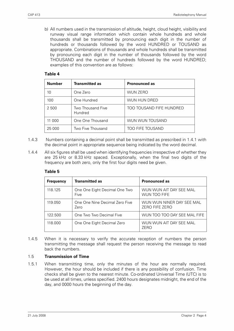
b) All numbers used in the transmission of altitude, height, cloud height, visibility andrunway visual range information which contain whole hundreds and wholethousands shall be transmitted by pronouncing each digit in the number ofhundreds or thousands followed by the word HUNDRED or TOUSAND asappropriate. Combinations of thousands and whole hundreds shall be transmittedby pronouncing each digit in the number of thousands followed by the wordTHOUSAND and the number of hundreds followed by the word HUNDRED;examples of this convention are as follows:
1.4.3 Numbers containing a decimal point shall be transmitted as prescribed in 1.4.1 withthe decimal point in appropriate sequence being indicated by the word decimal.
1.4.4 All six figures shall be used when identifying frequencies irrespective of whether theyare 25 kHz or 8.33 kHz spaced. Exceptionally, when the final two digits of thefrequency are both zero, only the first four digits need be given.
1.4.5 When it is necessary to verify the accurate reception of numbers the persontransmitting the message shall request the person receiving the message to readback the numbers.
1.5 Transmission of Time
1.5.1 When transmitting time, only the minutes of the hour are normally required.However, the hour should be included if there is any possibility of confusion. Timechecks shall be given to the nearest minute. Co-ordinated Universal Time (UTC) is tobe used at all times, unless specified. 2400 hours designates midnight, the end of theday, and 0000 hours the beginning of the day.
Table 4
Number Transmitted as Pronounced as
10 One Zero WUN ZERO
100 One Hundred WUN HUN DRED
2 500 Two Thousand Five Hundred
TOO TOUSAND FIFE HUNDRED
11 000 One One Thousand WUN WUN TOUSAND
25 000 Two Five Thousand TOO FIFE TOUSAND
Table 5
Frequency Transmitted as Pronounced as
118.125 One One Eight Decimal One Two Five
WUN WUN AIT DAY SEE MAL WUN TOO FIFE
119.050 One One Nine Decimal Zero Five Zero
WUN WUN NINER DAY SEE MAL ZERO FIFE ZERO
122.500 One Two Two Decimal Five WUN TOO TOO DAY SEE MAL FIFE
118.000 One One Eight Decimal Zero WUN WUN AIT DAY SEE MAL ZERO
Chapter 2 Page 421 July 2008

CAP 413 Radiotelephony Manual
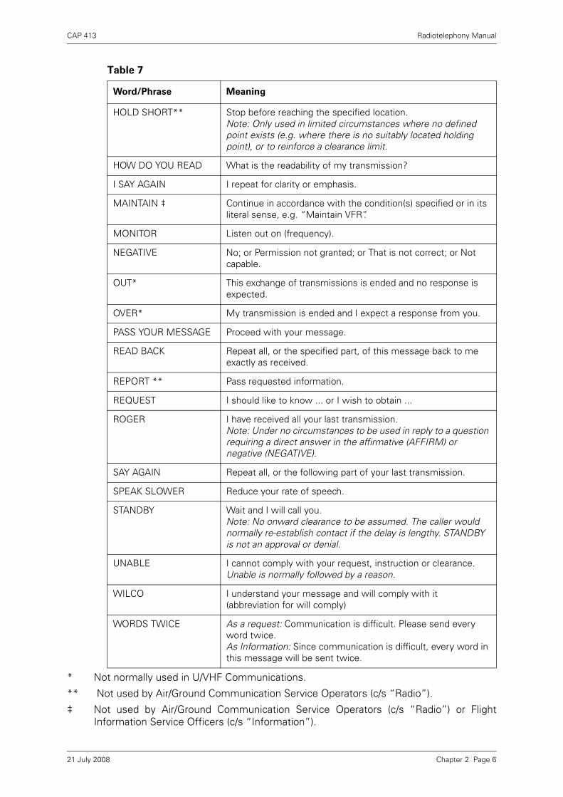
1.6 Standard Words and Phrases
The following words and phrases shall be used in radiotelephony communications asappropriate and shall have the meaning given below:
Table 6
Number Transmitted as Pronounced as
0823 Two Three or Zero Eight Two Three
TOO TREE (or ZERO AIT TOO TREE)
1300 One Three Zero Zero WUN TREE ZERO ZERO
2057 Five Seven or Two Zero Five Seven
FIFE SEVEN (or TOO ZERO FIFE SEVEN)
Table 7
Word/Phrase Meaning
ACKNOWLEDGE Let me know that you have received and understood this message.
AFFIRM Yes.
APPROVED** Permission for proposed action granted.
BREAK Indicates the separation between messages.
BREAK BREAK Indicates the separation between messages transmitted to different aircraft in a busy environment.
CANCEL Annul the previously transmitted clearance.
CHANGING TO I intend to call . . . (unit) on . . . (frequency).
CHECK Examine a system or procedure. (Not to be used in any other context. No answer is normally expected.)
CLEARED ‡ Authorised to proceed under the conditions specified.
CLIMB ‡ Climb and maintain.
CONFIRM I request verification of: (clearance, instruction, action, information).
CONTACT Establish communications with ... (your details have been passed).
CORRECT True or accurate.
CORRECTION An error has been made in this transmission (or message indicated). The correct version is ...
DESCEND ‡ Descend and maintain.
DISREGARD Ignore.
FANSTOP I am initiating a practice engine failure after take off. (Used only by pilots of single engine aircraft.) The response should be, “REPORT CLIMBING AWAY”.
FREECALL Call . . . (unit) (your details have not been passed – mainly used by military ATC).
Chapter 2 Page 521 July 2008
CAP 413 Radiotelephony Manual
* Not normally used in U/VHF Communications.
** Not used by Air/Ground Communication Service Operators (c/s “Radio”).
‡ Not used by Air/Ground Communication Service Operators (c/s “Radio”) or FlightInformation Service Officers (c/s “Information”).
HOLD SHORT** Stop before reaching the specified location.Note: Only used in limited circumstances where no defined point exists (e.g. where there is no suitably located holding point), or to reinforce a clearance limit.
HOW DO YOU READ What is the readability of my transmission?
I SAY AGAIN I repeat for clarity or emphasis.
MAINTAIN ‡ Continue in accordance with the condition(s) specified or in its literal sense, e.g. “Maintain VFR”.
MONITOR Listen out on (frequency).
NEGATIVE No; or Permission not granted; or That is not correct; or Not capable.
OUT* This exchange of transmissions is ended and no response is expected.
OVER* My transmission is ended and I expect a response from you.
PASS YOUR MESSAGE Proceed with your message.
READ BACK Repeat all, or the specified part, of this message back to me exactly as received.
REPORT ** Pass requested information.
REQUEST I should like to know ... or I wish to obtain ...
ROGER I have received all your last transmission. Note: Under no circumstances to be used in reply to a question requiring a direct answer in the affirmative (AFFIRM) or negative (NEGATIVE).
SAY AGAIN Repeat all, or the following part of your last transmission.
SPEAK SLOWER Reduce your rate of speech.
STANDBY Wait and I will call you. Note: No onward clearance to be assumed. The caller would normally re-establish contact if the delay is lengthy. STANDBY is not an approval or denial.
UNABLE I cannot comply with your request, instruction or clearance. Unable is normally followed by a reason.
WILCO I understand your message and will comply with it (abbreviation for will comply)
WORDS TWICE As a request: Communication is difficult. Please send every word twice. As Information: Since communication is difficult, every word in this message will be sent twice.
Table 7
Word/Phrase Meaning
Chapter 2 Page 621 July 2008

CAP 413 Radiotelephony Manual
1.7 Callsigns for Aeronautical Stations
1.7.1 Aeronautical stations are identified by the name of the location followed by a suffixexcept that the name of the rig/platform/vessel is normally used by offshore mineralextraction agencies. The suffix indicates the type of service being provided.
1.7.2 There are three main categories of aeronautical communications service:
• Air Traffic Control Service (ATC) which can only be provided by licensed Air TrafficControl Officers who are closely regulated by the CAA.
• Flight Information Service at aerodromes can be provided only by licensedAerodrome Flight Information Service Officers (AFISOs), who are also regulated bythe CAA.
• Aerodrome Air/Ground Communication Service (AGCS) which can be provided byRadio Operators who are not licensed but have obtained a certificate ofcompetency to operate radio equipment on aviation frequencies from the CAA.These operations come under the jurisdiction of the radio licence holder, but arenot regulated in any other way.
1.7.3 It is an offence to use a callsign for a purpose other than that for which it has beennotified.
1.7.4 When satisfactory communication has been established, and provided that it will not
be confusing, the name of the location or the callsign suffix may be omitted.
1.7.5 It is correct procedure to announce identity on all telephone calls: with incoming callsit is the opening remark and with outgoing calls it is the reply to the recipient’sannouncement of identity. AFISOs and AGCS operators must never identifythemselves as '....air traffic control'. It is just as important that this procedure is notrelaxed for direct telephone lines because mistaken identity can occur when anotherline has been inadvertently left open from a previous call. The identity to be used isthat of the function relative to the telephone extension being used.
Table 8
Service Suffix
Area Control CONTROL
Radar (in general) RADAR
Approach Control APPROACH
Aerodrome Control TOWER
Approach Control RadarArrival/Departure
DIRECTOR/DEPARTURE (RADAR – when tasks combined)/ARRIVAL – (when approved))
Ground Movement Control GROUND
Precision Approach Radar TALKDOWN (Military – FINAL CONTROLLER)
Flight Information INFORMATION
Air/Ground Communication Service
RADIO
Ground Movement Planning
DELIVERY
Chapter 2 Page 721 July 2008

CAP 413 Radiotelephony Manual
1.8 Callsigns for Aircraft
1.8.1 When establishing communication, an aircraft shall use the full callsigns of bothstations.
1.8.2 After satisfactory communication has been established and provided that noconfusion is likely to occur, the ground station may abbreviate callsigns (see tablebelow). A pilot may only abbreviate the callsign of his aircraft if it has first beenabbreviated by the aeronautical station.
* The name of either the aircraft manufacturer, or name of aircraft model, or name ofthe aircraft category (e.g. helicopter or gyrocopter) may be used as a prefix to thecallsign.
1.8.3 An aircraft should request the service required on initial contact when freecalling aground station.
1.8.4 An aircraft shall not change its callsign type during a flight. However, where there isa likelihood that confusion may occur because of similar callsigns, an aircraft may beinstructed by an air traffic service unit (ATSU) to change the type of its callsigntemporarily.
1.8.5 Aircraft in the heavy vortex wake category shall include the word ‘HEAVY’immediately after the aircraft callsign in the initial call to each ATSU.
1.8.6 On initial contact, student pilots who are flying solo shall use the callsign prefix‘STUDENT’1. Once acknowledged, it will not normally be necessary for student pilotsto use the prefix in subsequent transmissions until making initial contact with other
Borton Tower G-ABCD request Flight Information Service
G-ABCD Borton Tower pass your message
Table 9
Full callsign Abbreviation
GBFRM G-RM
Speedbird GBGDC Speedbird DC
N31029 N029
N753DA N3DA
Midland 640 No abbreviation
* Piper GBSZT Piper ZT
Westbury Approach, G-ABCD request Radar Information Service
Wrayton Control, G-ABCD I wish to file an airborne flight plan
1. Although intended primarily for use by ab initio students, the prefix shall also be used in other circumstances where, for example, the holder of a valid licence is returning to flying practice after a significant absence and is undergoing renewal training involving solo flight conducted as a student under the supervision of a flight instructor.
Chapter 2 Page 821 July 2008
CAP 413 Radiotelephony Manual
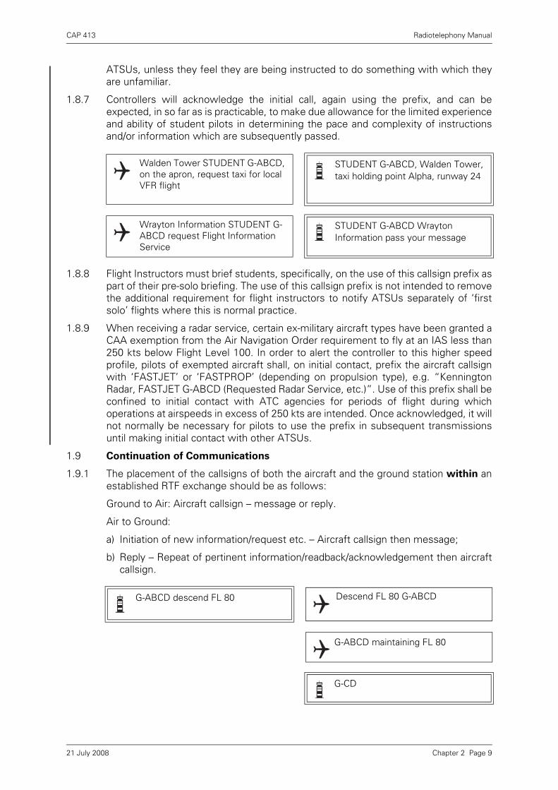
ATSUs, unless they feel they are being instructed to do something with which theyare unfamiliar.
1.8.7 Controllers will acknowledge the initial call, again using the prefix, and can beexpected, in so far as is practicable, to make due allowance for the limited experienceand ability of student pilots in determining the pace and complexity of instructionsand/or information which are subsequently passed.
1.8.8 Flight Instructors must brief students, specifically, on the use of this callsign prefix aspart of their pre-solo briefing. The use of this callsign prefix is not intended to removethe additional requirement for flight instructors to notify ATSUs separately of ‘firstsolo’ flights where this is normal practice.
1.8.9 When receiving a radar service, certain ex-military aircraft types have been granted aCAA exemption from the Air Navigation Order requirement to fly at an IAS less than250 kts below Flight Level 100. In order to alert the controller to this higher speedprofile, pilots of exempted aircraft shall, on initial contact, prefix the aircraft callsignwith ‘FASTJET’ or ‘FASTPROP’ (depending on propulsion type), e.g. “KenningtonRadar, FASTJET G-ABCD (Requested Radar Service, etc.)”. Use of this prefix shall beconfined to initial contact with ATC agencies for periods of flight during whichoperations at airspeeds in excess of 250 kts are intended. Once acknowledged, it willnot normally be necessary for pilots to use the prefix in subsequent transmissionsuntil making initial contact with other ATSUs.
1.9 Continuation of Communications
1.9.1 The placement of the callsigns of both the aircraft and the ground station within anestablished RTF exchange should be as follows:
Ground to Air: Aircraft callsign – message or reply.
Air to Ground:
a) Initiation of new information/request etc. – Aircraft callsign then message;
b) Reply – Repeat of pertinent information/readback/acknowledgement then aircraftcallsign.
Walden Tower STUDENT G-ABCD, on the apron, request taxi for local VFR flight
STUDENT G-ABCD, Walden Tower, taxi holding point Alpha, runway 24
Wrayton Information STUDENT G-ABCD request Flight Information Service
STUDENT G-ABCD Wrayton Information pass your message
G-ABCD descend FL 80 Descend FL 80 G-ABCD
G-ABCD maintaining FL 80
G-CD
Chapter 2 Page 921 July 2008
CAP 413 Radiotelephony Manual
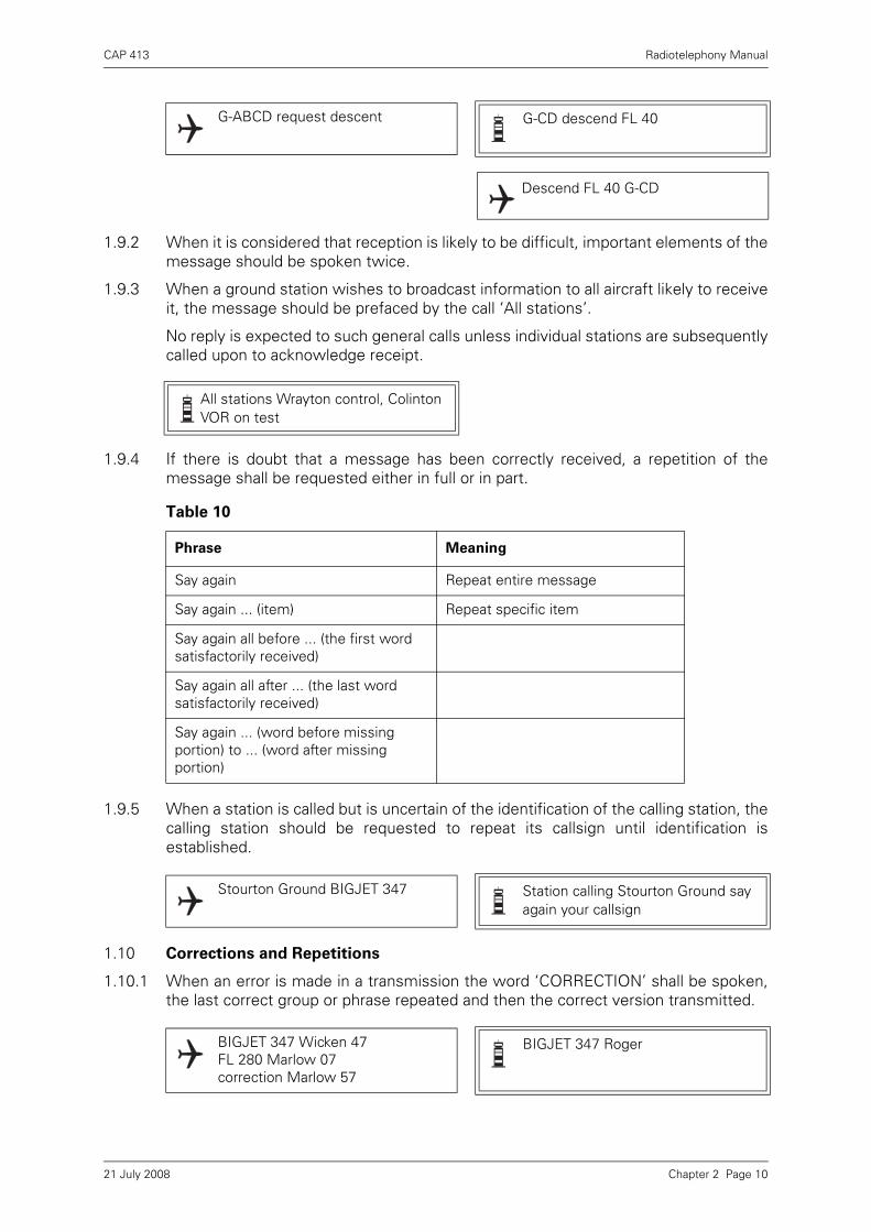
1.9.2 When it is considered that reception is likely to be difficult, important elements of themessage should be spoken twice.
1.9.3 When a ground station wishes to broadcast information to all aircraft likely to receiveit, the message should be prefaced by the call ‘All stations’.
No reply is expected to such general calls unless individual stations are subsequentlycalled upon to acknowledge receipt.
1.9.4 If there is doubt that a message has been correctly received, a repetition of themessage shall be requested either in full or in part.
1.9.5 When a station is called but is uncertain of the identification of the calling station, thecalling station should be requested to repeat its callsign until identification isestablished.
1.10 Corrections and Repetitions
1.10.1 When an error is made in a transmission the word ‘CORRECTION’ shall be spoken,the last correct group or phrase repeated and then the correct version transmitted.
G-ABCD request descent G-CD descend FL 40
Descend FL 40 G-CD
All stations Wrayton control, Colinton VOR on test
Table 10
Phrase Meaning
Say again Repeat entire message
Say again ... (item) Repeat specific item
Say again all before ... (the first word satisfactorily received)
Say again all after ... (the last word satisfactorily received)
Say again ... (word before missing portion) to ... (word after missing portion)
Stourton Ground BIGJET 347 Station calling Stourton Ground say again your callsign
BIGJET 347 Wicken 47 FL 280 Marlow 07correction Marlow 57
BIGJET 347 Roger
Chapter 2 Page 1021 July 2008

CAP 413 Radiotelephony Manual
1.10.2 If a correction can best be made by repeating the entire message, the operator shalluse the phrase ‘CORRECTION I SAY AGAIN’ before transmitting the message asecond time.
1.11 Acknowledgement of Receipt
Acknowledgements of information should be signified by the use of the receivingstations’ callsign or Roger callsign, and not by messages such as: ‘callsign-copy theweather’ or ‘callsign-copy the traffic’.
1.12 Transfer of Communications
1.12.1 An aircraft will normally be advised by the appropriate aeronautical station to changefrom one radio frequency to another in accordance with agreed procedures.
In the absence of such advice, the aircraft shall notify the aeronautical station
before such a change takes place. Aircraft flying in controlled airspace must obtainpermission from the controlling authority before changing frequency.
1.12.2 An aircraft may be instructed to ‘standby’ on a frequency when it is intended that theATSU will initiate communications, and to monitor a frequency on which informationis being broadcast.
1.12.3 If the airspace does not dictate that an aircraft must remain in contact with a specificATSU and the pilot wishes to freecall another agency he should request, or notifysuch an intention.
1.13 Clearance Issue and Read Back Requirements
1.13.1 Provisions governing clearances are contained in the PANS-ATM (ICAO Doc 4444). Aclearance may vary in content from a detailed description of the route and levels tobe flown to a brief standard instrument departure (SID) according to local procedures.
1.13.2 Controllers will pass a clearance slowly and clearly since the pilot needs to write itdown; wasteful repetition will thus be avoided. Whenever possible, a route clearanceshould be passed to an aircraft before start up and the aircraft’s full callsign will alwaysbe used. Generally, controllers will avoid passing a clearance to a pilot engaged
BIGJET 347 contact Wrayton Control 129.125
Wrayton Control 129.125 BIGJET 347
BIGJET 347 standby 118.950 for Kennington Tower
Standby 118.950 for Kennington Tower BIGJET 347
BIGJET 347 monitor 128.275 for ATIS
Monitor 128.275 for ATIS BIGJET 347
Westbury G-ABCD request change to Wrayton Information on 125.750
Wrayton Information G-ABCD changing to Wrayton Centre on 121.5 for Practice Pan
Chapter 2 Page 1121 July 2008

CAP 413 Radiotelephony Manual
in complicated taxiing manoeuvres and on no occasion when the pilot is
engaged in line up or take-off manoeuvres.
1.13.3 An ATC route clearance is NOT an instruction to take-off or enter an active runway.The words ‘TAKE-OFF’ are used only when an aircraft is cleared for take-off. At
all other times the word ‘DEPARTURE’ is used.
1.13.4 The stringency of the read back requirement is directly related to the possibleseriousness of a misunderstanding in the transmission and receipt of ATC clearanceand instructions. ATC route clearances shall always be read back unless
otherwise authorised by the appropriate ATS authority in which case they shallbe acknowledged in a positive manner. Read backs shall always include the aircraftcallsign.
1.13.5 The ATS messages listed below are to be read back in full by the pilot/driver. If areadback is not received the pilot/driver will be asked to do so. Similarly, the pilot/driver is expected to request that instructions are repeated or clarified if any are notfully understood.
Taxi/Towing Instructions
Level Instructions
Heading Instructions
Speed Instructions
Airways or Route Clearances
Approach Clearances
Runway-in-Use
BIGJET 347 cleared to Kennington via A1, at FL 60, request level change en-route, squawk 5501
Cleared to Kennington via A1, at FL 60, request level change en-route, squawk 5501 BIGJET 347
BIGJET 347 correct
BIGJET 347 cleared to Kennington via A1, Wicken 3 Delta departure, squawk 5501
Cleared to Kennington via A1, Wicken 3 Delta departure, squawk 5501, BIGJET 347
BIGJET 347 correct
G-ABCD after departure cleared to zone boundary via route Echo. Climb to altitude 2000 feet QNH 1008, squawk 6522
After departure cleared to zone boundary via route Echo. Climb to altitude 2000 feet QNH 1008, squawk 6522 G-ABCD
G-CD correct
Chapter 2 Page 1221 July 2008
CAP 413 Radiotelephony Manual
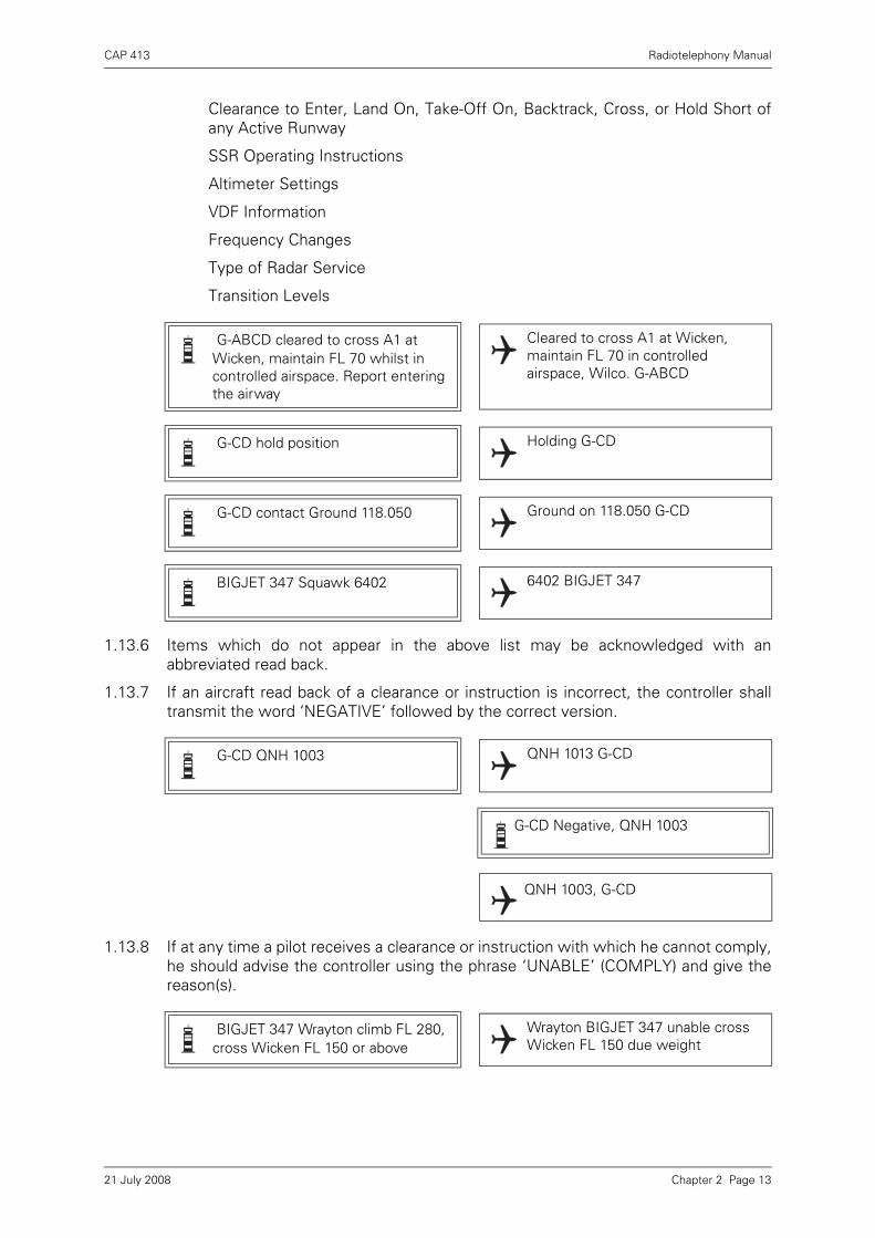
Clearance to Enter, Land On, Take-Off On, Backtrack, Cross, or Hold Short ofany Active Runway
SSR Operating Instructions
Altimeter Settings
VDF Information
Frequency Changes
Type of Radar Service
Transition Levels
1.13.6 Items which do not appear in the above list may be acknowledged with anabbreviated read back.
1.13.7 If an aircraft read back of a clearance or instruction is incorrect, the controller shalltransmit the word ‘NEGATIVE’ followed by the correct version.
1.13.8 If at any time a pilot receives a clearance or instruction with which he cannot comply,he should advise the controller using the phrase ‘UNABLE’ (COMPLY) and give thereason(s).
G-ABCD cleared to cross A1 at Wicken, maintain FL 70 whilst in controlled airspace. Report entering the airway
Cleared to cross A1 at Wicken, maintain FL 70 in controlled airspace, Wilco. G-ABCD
G-CD hold position Holding G-CD
G-CD contact Ground 118.050 Ground on 118.050 G-CD
BIGJET 347 Squawk 6402 6402 BIGJET 347
G-CD QNH 1003 QNH 1013 G-CD
G-CD Negative, QNH 1003
QNH 1003, G-CD
BIGJET 347 Wrayton climb FL 280, cross Wicken FL 150 or above
Wrayton BIGJET 347 unable cross Wicken FL 150 due weight
Chapter 2 Page 1321 July 2008

CAP 413 Radiotelephony Manual
1.14 Simultaneous Transmissions
1.14.1 Direct communications between pilots and ATSUs can be adversely affected bysimultaneous transmissions which, effectively, block all or part of intendedmessages. Moreover, whilst the situation may be apparent to the controller oranother pilot, the individuals who inadvertently make such transmissions may beunaware. On hearing a simultaneous transmission it can be helpful for the controller(or another pilot if it is the controller’s transmission which has been blocked) to drawattention to the situation using the word ‘blocked’.
1.14.1.1 Controller Example (where pilots have transmitted simultaneously):
1.14.1.2 Pilot Example (where another pilot has blocked a controller’s transmission):
1.15 Complying with Clearances and Instructions
1.15.1 Pilots are expected to comply with clearances and instructions promptly,commensurate with normal aircraft operations. If, for any reason, a pilot does notwish to comply with an instruction promptly, the pilot should advise the ATS unit andgive an indication of when he intends to comply.
1.15.2 If an ATS unit wishes to indicate that time of compliance is at the pilot's discretion,the ATS message will include the phrase 'when ready'.
1.15.3 If an ATS unit wishes to indicate that the clearance or instruction is required to becomplied with at a particular point in the flight, the message will include the phrase'after passing'.
1.15.4 If an ATS unit wishes to indicate that the instruction or clearance must be compliedwith at once, the controller's message will include the word 'now' or 'immediately'.Use of the word 'now' indicates that the instruction should be complied with inaccordance with normal aircraft operating procedures, but without undue delay. Useof the word 'immediately' indicates a further degree of urgency exists (e.g. to avoidflight into terrain or restricted airspace, or for the provision of collision avoidance, seeChapter 5 Paragraph 1.6.4 Avoiding Action Phraseology). In such circumstances, thepilot should take action to comply with the instruction as soon as practicable, subjectto the safety of the aircraft.
1.15.5 In order to ensure any restriction is not blocked by a pilot acknowledgement, thephrase or word, indicating when a clearance or instruction should be complied with,will normally be placed before the executive instruction (Para 1.15.6, 1st and 2ndexamples), but in certain cases the phrase or word may be placed between theinstruction and the value of the instruction (Para 1.15.6, 3rd and 4th examples).
1.15.6 The phrases and words described in this section are most commonly used inassociation with level instructions (see also Chapter 3, Level Reporting, Paragraph1.2.3.3 and Paragraph 1.2.3.4), but may be used in other circumstances if appropriate.Examples are shown below:
Transmission Blocked – (callsign if known) say again
Transmission Blocked – Wrayton say again, BIGJET 345
BIGJET 347 after passing North Cross, descend FL 80
After passing North Cross, descend FL 80, BIGJET 347
Chapter 2 Page 1421 July 2008

CAP 413 Radiotelephony Manual
1.16 Communication Failure
1.16.1 Air – Ground
a) Check the following points:
i) The correct frequency has been selected for the route being flown.
ii) The Aeronautical Station being called is open for watch.
iii) The aircraft is not out of radio range.
iv) Receiver volume correctly set.
b) If the previous points are in order it may be that the aircraft equipment is notfunctioning correctly. Complete the checks of headset and radio installationappropriate to the aircraft.
c) When an aircraft station is unable to establish contact with the aeronautical stationon the designated frequency it shall attempt to establish contact on anotherfrequency appropriate to the route being flown. If this attempt fails, the aircraftstation shall attempt to establish communication with other aircraft or otheraeronautical stations on frequencies appropriate to the route.
d) The pilot may still be unable to establish communication on any designatedaeronautical station frequency, or with any other aircraft. The pilot is then totransmit his message twice on the designated frequency, including the addresseefor whom the message is intended, preceded by the phrase ‘TRANSMITTINGBLIND’ in case the transmitter is still functioning.
e) Where a transmitter failure is suspected, check or change the microphone. Listenout on the designated frequency for instructions. It should be possible to answerquestions by use of the carrier wave if the microphone is not functioning (seeChapter 8 paragraph 1.6).
f) In the case of a receiver failure transmit reports twice at the scheduled times orpositions on the designated frequency preceded by the phrase ‘TRANSMITTINGBLIND DUE TO RECEIVER FAILURE’.
g) An aircraft which is being provided with air traffic control service, advisory serviceor aerodrome flight information service is to transmit information regarding theintention of the pilot in command with respect to the continuation of the flight.Specific procedures for the action to be taken by pilots of IFR and Special VFRflights are contained in the appropriate AIP ENR and/or AD sections.
1.16.2 Ground – Air
1.16.2.1 After completing checks of ground equipment (most airports have standby andemergency communications equipment) the ground station will request other
BIGJET 347, when ready descend FL170, Report leaving FL210
When ready descend FL170. Report leaving FL210, BIGJET 347
BIGJET 347, reduce speed now 210 kts
Reducing speed now 210 kts BIGJET 347
BIGJET 347, climb immediately FL35
Climbing immediately FL35, BIGJET 347
Chapter 2 Page 1521 July 2008
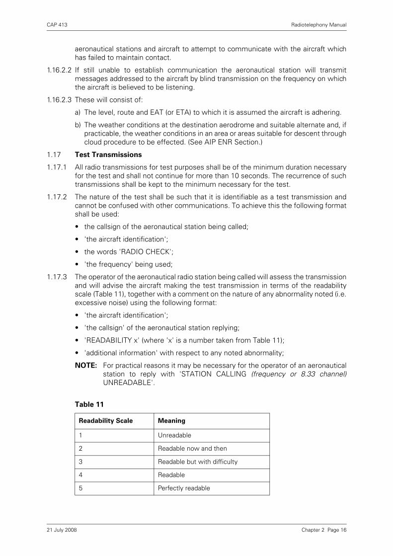
CAP 413 Radiotelephony Manual
aeronautical stations and aircraft to attempt to communicate with the aircraft whichhas failed to maintain contact.
1.16.2.2 If still unable to establish communication the aeronautical station will transmitmessages addressed to the aircraft by blind transmission on the frequency on whichthe aircraft is believed to be listening.
1.16.2.3 These will consist of:
a) The level, route and EAT (or ETA) to which it is assumed the aircraft is adhering.
b) The weather conditions at the destination aerodrome and suitable alternate and, ifpracticable, the weather conditions in an area or areas suitable for descent throughcloud procedure to be effected. (See AIP ENR Section.)
1.17 Test Transmissions
1.17.1 All radio transmissions for test purposes shall be of the minimum duration necessaryfor the test and shall not continue for more than 10 seconds. The recurrence of suchtransmissions shall be kept to the minimum necessary for the test.
1.17.2 The nature of the test shall be such that it is identifiable as a test transmission andcannot be confused with other communications. To achieve this the following formatshall be used:
• the callsign of the aeronautical station being called;
• 'the aircraft identification';
• the words 'RADIO CHECK';
• 'the frequency' being used;
1.17.3 The operator of the aeronautical radio station being called will assess the transmissionand will advise the aircraft making the test transmission in terms of the readabilityscale (Table 11), together with a comment on the nature of any abnormality noted (i.e.excessive noise) using the following format:
• 'the aircraft identification';
• 'the callsign' of the aeronautical station replying;
• 'READABILITY x' (where 'x' is a number taken from Table 11);
• 'additional information' with respect to any noted abnormality;
NOTE: For practical reasons it may be necessary for the operator of an aeronauticalstation to reply with 'STATION CALLING (frequency or 8.33 channel)UNREADABLE'.
Table 11
Readability Scale Meaning
1 Unreadable
2 Readable now and then
3 Readable but with difficulty
4 Readable
5 Perfectly readable
Chapter 2 Page 1621 July 2008
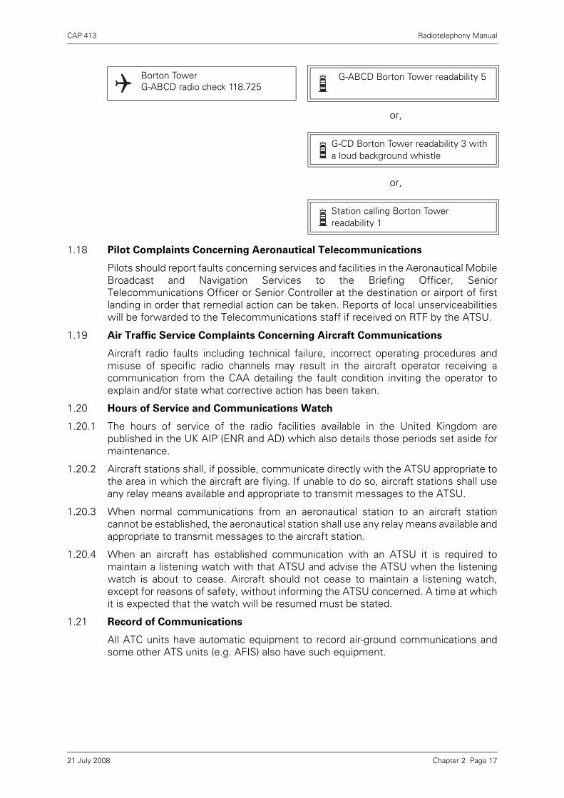
CAP 413 Radiotelephony Manual
or,
or,
1.18 Pilot Complaints Concerning Aeronautical Telecommunications
Pilots should report faults concerning services and facilities in the Aeronautical MobileBroadcast and Navigation Services to the Briefing Officer, SeniorTelecommunications Officer or Senior Controller at the destination or airport of firstlanding in order that remedial action can be taken. Reports of local unserviceabilitieswill be forwarded to the Telecommunications staff if received on RTF by the ATSU.
1.19 Air Traffic Service Complaints Concerning Aircraft Communications
Aircraft radio faults including technical failure, incorrect operating procedures andmisuse of specific radio channels may result in the aircraft operator receiving acommunication from the CAA detailing the fault condition inviting the operator toexplain and/or state what corrective action has been taken.
1.20 Hours of Service and Communications Watch
1.20.1 The hours of service of the radio facilities available in the United Kingdom arepublished in the UK AIP (ENR and AD) which also details those periods set aside formaintenance.
1.20.2 Aircraft stations shall, if possible, communicate directly with the ATSU appropriate tothe area in which the aircraft are flying. If unable to do so, aircraft stations shall useany relay means available and appropriate to transmit messages to the ATSU.
1.20.3 When normal communications from an aeronautical station to an aircraft stationcannot be established, the aeronautical station shall use any relay means available andappropriate to transmit messages to the aircraft station.
1.20.4 When an aircraft has established communication with an ATSU it is required tomaintain a listening watch with that ATSU and advise the ATSU when the listeningwatch is about to cease. Aircraft should not cease to maintain a listening watch,except for reasons of safety, without informing the ATSU concerned. A time at whichit is expected that the watch will be resumed must be stated.
1.21 Record of Communications
All ATC units have automatic equipment to record air-ground communications andsome other ATS units (e.g. AFIS) also have such equipment.
Borton TowerG-ABCD radio check 118.725
G-ABCD Borton Tower readability 5
G-CD Borton Tower readability 3 with a loud background whistle
Station calling Borton Tower readability 1
Chapter 2 Page 1721 July 2008
CAP 413 Radiotelephony Manual
1.22 Categories of Message
The categories of messages handled by the aeronautical mobile service are in thefollowing order of priority:
a) Distress messages See Chapter 8 – Emergency Phraseology
b) Urgency messages } c) Communications relating
to direction finding See Chapter 6 paragraph 1.7
d) Flight safety messages See Chapter 9 paragraph 1.6
e) Meteorological messages See Chapter 4 paragraph 7
f) Flight Regularity messages See Chapter 9 paragraph 1.6.
Chapter 2 Page 1821 July 2008

CAP 413 Radiotelephony Manual
Chapter 3 General Phraseology
1 General
1.1 Introduction
1.1.1 The phraseology detailed in this manual has been established for the purpose ofensuring uniformity in RTF communications. Communications shall be concise andunambiguous, using standard phraseology for all situations for which it is specified.Obviously, it is not practicable to detail phraseology examples suitable for everysituation. However, if standard phrases are adhered to when composing a message,any possible ambiguity will be reduced to a minimum. Only when standardphraseology cannot serve an intended transmission, shall plain language be used.
1.1.2 Some abbreviations, which by their common usage have become part of aviationterminology, may be spoken using their constituent letters rather than the spellingalphabet, for example, ILS, QNH, RVR, etc., (see Chapter 1, paragraph 1.2).
1.1.3 For all transmissions, with the exception of those used for surveillance radarapproaches or precision radar approaches, the word 'degrees' shall be appended toheading figures where the heading ends in zero, or in cases where confusion orambiguity may result.
1.1.4 For all transmissions, the word 'millibar' shall be appended to figures whentransmitting a pressure setting below 1000 mb, or in cases where confusion orambiguity may result.
1.1.5 The following words may be omitted from transmissions provided that no confusionor ambiguity may result:
a) ‘Surface’ and ‘knots’ in relation to surface wind direction and speed.
b) ‘Degrees’ in relation to surface wind direction.
c) ‘Visibility’, ‘cloud’ and ‘height’ in meteorological reports.
d) ‘over’, ‘roger’ and ‘out’.
1.1.6 The excessive use of courtesies should be avoided.
1.2 Level Reporting
1.2.1 Only basic level instructions are detailed in this Chapter. More comprehensivephrases are contained in subsequent chapters in the context in which they are mostcommonly used.
1.2.2 The precise phraseology used in the transmission and acknowledgement of climb anddescent clearances will vary, depending upon the circumstances, traffic density andnature of the flight operations.
1.2.3 However, care must be taken to ensure that misunderstandings are not generated asa consequence of the phraseology employed during these phases of flight. Forexample, levels may be reported as altitude, height or flight levels according to thephase of flight and the altimeter setting. Therefore, when passing level messages,the following conventions apply:
a) The word ‘to’ is to be omitted from messages relating to FLIGHT LEVELS.
b) All messages relating to an aircraft’s climb or descent to a HEIGHT or ALTITUDEemploy the word ‘to’ followed immediately by the word HEIGHT or ALTITUDE.Furthermore, the initial message in any such RTF exchange will also include theappropriate QFE or QNH.
Chapter 3 Page 121 July 2008
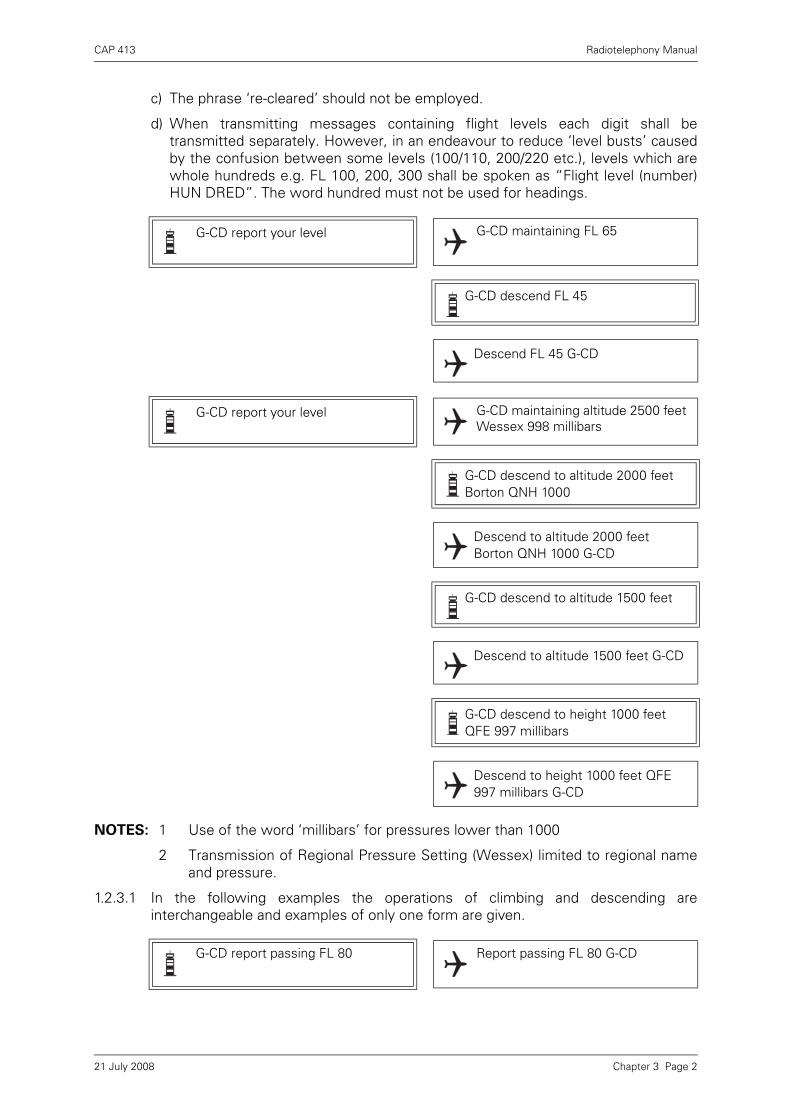
CAP 413 Radiotelephony Manual
c) The phrase ‘re-cleared’ should not be employed.
d) When transmitting messages containing flight levels each digit shall betransmitted separately. However, in an endeavour to reduce ‘level busts’ causedby the confusion between some levels (100/110, 200/220 etc.), levels which arewhole hundreds e.g. FL 100, 200, 300 shall be spoken as “Flight level (number)HUN DRED”. The word hundred must not be used for headings.
NOTES: 1 Use of the word ‘millibars’ for pressures lower than 1000
2 Transmission of Regional Pressure Setting (Wessex) limited to regional nameand pressure.
1.2.3.1 In the following examples the operations of climbing and descending areinterchangeable and examples of only one form are given.
G-CD report your level G-CD maintaining FL 65
G-CD descend FL 45
Descend FL 45 G-CD
G-CD report your level G-CD maintaining altitude 2500 feet Wessex 998 millibars
G-CD descend to altitude 2000 feet Borton QNH 1000
Descend to altitude 2000 feet Borton QNH 1000 G-CD
G-CD descend to altitude 1500 feet
Descend to altitude 1500 feet G-CD
G-CD descend to height 1000 feet QFE 997 millibars
Descend to height 1000 feet QFE 997 millibars G-CD
G-CD report passing FL 80 Report passing FL 80 G-CD
Chapter 3 Page 221 July 2008

CAP 413 Radiotelephony Manual
1.2.3.2 Exceptionally, a best rate of climb or descent may be required. Pilots of aircraftoperating within controlled airspace in the London and Scottish FIRs have beeninstructed not to operate with a climb or descent rate in excess of 8000 ft/min. Aircraftin an emergency and certain military activities are exempt from this restriction.
or,
1.2.3.3 Under exceptional circumstances, if instant descent/climb is required, the word‘immediately’ shall be used.
G-CD passing FL 80
G-CD maintain altitude 2500 feet Maintaining altitude 2500 feet G-CD
G-CD climb FL 70 Climb FL 70 G-CD
G-CD reaching FL 70
G-CD request descent G-CD descend FL 60
Descend FL 60 G-CD
BIGJET 347 after passing North Cross descend FL 80
After passing North Cross descend FL 80 BIGJET 347
BIGJET 347 stop descent FL 210 Stop descent FL 210 BIGJET 347
BIGJET 347 expedite descent FL 180
Expedite descent FL 180 BIGJET 347
BIGJET 347 climb FL 280 expedite until passing FL 180
Climb FL 280 expedite until passing FL 180 BIGJET 347
BIGJET 347 unable expedite climb due weight
BIGJET 347 descend immediatelyFL 200 due traffic
Descend immediately FL 200 BIGJET 347
Chapter 3 Page 321 July 2008

CAP 413 Radiotelephony Manual
1.2.3.4 Pilots are expected to comply with ATC instructions as soon as they are issued.
However, when a climb/descent is left to the discretion of the pilot, the words ‘whenready’ shall be used; in these circumstances the pilot will report ‘leaving’ his presentlevel. Should pilots be instructed to report leaving a level, they should inform
ATC that they have left an assigned level only when the aircraft’s altimeter
indicates that the aircraft has actually departed from that level and is
maintaining a positive rate of climb or descent, in accordance with published
procedures.
1.2.4 Except as described in paragraph 1.3, a pilot receiving a Radar Control Service is notrequired to report leaving a level, passing a level, or reaching a level, unlessspecifically requested to do so.
NOTE: Pilots receiving a Radar Advisory Service (RAS) must report before changingheading or level, or if receiving a Radar Information Service (RIS), must reportbefore changing level, level band or route (as described in the UK AIP ENR1.6.1, Use of Radar in Air Traffic Services).
1.3 Initial Call - IFR flights
1.3.1 Format of Initial Calls
Pilots of aircraft flying Instrument Departures (including those outside controlledairspace) shall include the following information on initial contact with the first en-route ATS Unit (see also Chapter 6 Approach Phraseology Paragraph 1.1.2):
a) Callsign;
b) SID or Standard Departure Route Designator (where appropriate);
c) Current or passing level; PLUS
d) Initial climb level (i.e. the first level at which the aircraft will level off unlessotherwise cleared. For example, on a Standard Instrument Departure that involvesa stepped climb profile, the initial climb level will be the first level specified in theprofile).
BIGJET 347 when ready climb FL 280
When ready climb FL 280 BIGJET 347
BIGJET 347 leaving FL 200 climbing FL 280
BIGJET 347
Westbury Departure, BIGJET 347, BIGRO 5D, Passing Altitude 2300 feet climbing FL80
BIGJET 347, Westbury, Roger
Chapter 3 Page 421 July 2008
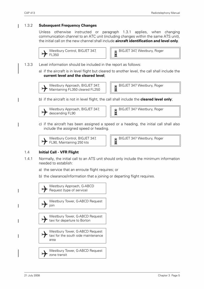
CAP 413 Radiotelephony Manual
1.3.2 Subsequent Frequency Changes
Unless otherwise instructed or paragraph 1.3.1 applies, when changingcommunication channel to an ATC unit (including changes within the same ATS unit),the initial call on the new channel shall include aircraft identification and level only.
1.3.3 Level information should be included in the report as follows:
a) if the aircraft is in level flight but cleared to another level, the call shall include thecurrent level and the cleared level;
b) if the aircraft is not in level flight, the call shall include the cleared level only;
if
c) if the aircraft has been assigned a speed or a heading, the initial call shall alsoinclude the assigned speed or heading.
1.4 Initial Call - VFR Flight
1.4.1 Normally, the initial call to an ATS unit should only include the minimum informationneeded to establish:
a) the service that an enroute flight requires; or
b) the clearance/information that a joining or departing flight requires.
Westbury Control, BIGJET 347, FL350
BIGJET 347, Westbury, Roger
Westbury Approach, BIGJET 347, Maintaining FL350 cleared FL250
BIGJET 347 Westbury, Roger
Westbury Approach, BIGJET 347, descending FL90
BIGJET 347 Westbury, Roger
Westbury Control, BIGJET 347, FL90, Maintaining 250 kts
BIGJET 347 Westbury, Roger
Westbury Approach, G-ABCD Request (type of service)
Westbury Tower, G-ABCD Request join
Westbury Tower, G-ABCD Request taxi for departure to Borton
Westbury Tower, G-ABCD Request taxi for the south side maintenance area
Westbury Tower, G-ABCD Request zone transit
Chapter 3 Page 521 July 2008
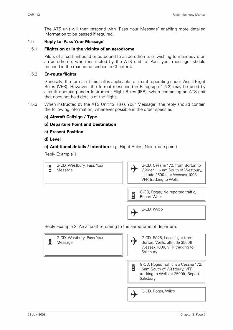
CAP 413 Radiotelephony Manual
The ATS unit will then respond with ‘Pass Your Message’ enabling more detailedinformation to be passed if required.
1.5 Reply to 'Pass Your Message'
1.5.1 Flights on or in the vicinity of an aerodrome
Pilots of aircraft inbound or outbound to an aerodrome, or wishing to manoeuvre onan aerodrome, when instructed by the ATS unit to 'Pass your message' shouldrespond in the manner described in Chapter 4.
1.5.2 En-route flights
Generally, the format of this call is applicable to aircraft operating under Visual FlightRules (VFR). However, the format (described in Paragraph 1.5.3) may be used byaircraft operating under Instrument Flight Rules (IFR), when contacting an ATS unitthat does not hold details of the flight.
1.5.3 When instructed by the ATS Unit to 'Pass Your Message', the reply should containthe following information, whenever possible in the order specified:
a) Aircraft Callsign / Type
b) Departure Point and Destination
c) Present Position
d) Level
e) Additional details / Intention (e.g. Flight Rules, Next route point)
Reply Example 1:
Reply Example 2: An aircraft returning to the aerodrome of departure.
G-CD, Westbury, Pass Your Message
G-CD, Cessna 172, from Borton to Walden, 15 nm South of Westbury, altitude 2500 feet Wessex 1008, VFR tracking to Wells
G-CD, Roger, No reported traffic, Report Wells
G-CD, Wilco
G-CD, Westbury, Pass Your Message
G-CD, PA28, Local flight from Borton, Wells, altitude 3500ft Wessex 1008, VFR tracking to Salisbury
G-CD, Roger, Traffic is a Cessna 172, 15nm South of Westbury, VFR tracking to Wells at 2500ft, Report Salisbury
G-CD, Roger, Wilco
Chapter 3 Page 621 July 2008

CAP 413 Radiotelephony Manual
1.6 Position Reporting
1.6.1 Position reports shall contain the following elements of information:
a) Aircraft identification
b) Position
c) Time
d) Level
e) Next position and ETA
1.6.2 Where adequate flight progress data is available from other sources, such as groundradar, aircraft may be exempted from the requirement to make compulsory positionreports.
1.7 Flight Plans
1.7.1 A pilot may file a flight plan with an ATSU during flight, although the use of busy RTFchannels should be avoided; normally the FIS frequency should be used.
1.7.2 The format for an airborne flight plan is as follows:
a) Aircraft identification and type.
b) Position and heading.
c) Level and flight conditions.
d) Departure aerodrome.
e) Estimated time at entry point.
BIGJET 347 Wicken 47 FL 280 Marlow 57
BIGJET 347
G-ABCD Wrayton Information report mid-channel
Wilco G-ABCD
G-ABCD mid-channel 25Altitude 3500Greenpoint 40
G-ABCD
BIGJET 347 next report at Colinton Wilco BIGJET 347
BIGJET 347 omit position reports this frequency
Wilco BIGJET 347
BIGJET 347 resume position reporting
Wilco BIGJET 347
Wrayton Control G-ABCD I wish to file an airborne flight plan
G-ABCD Wrayton Control pass your message
Chapter 3 Page 721 July 2008
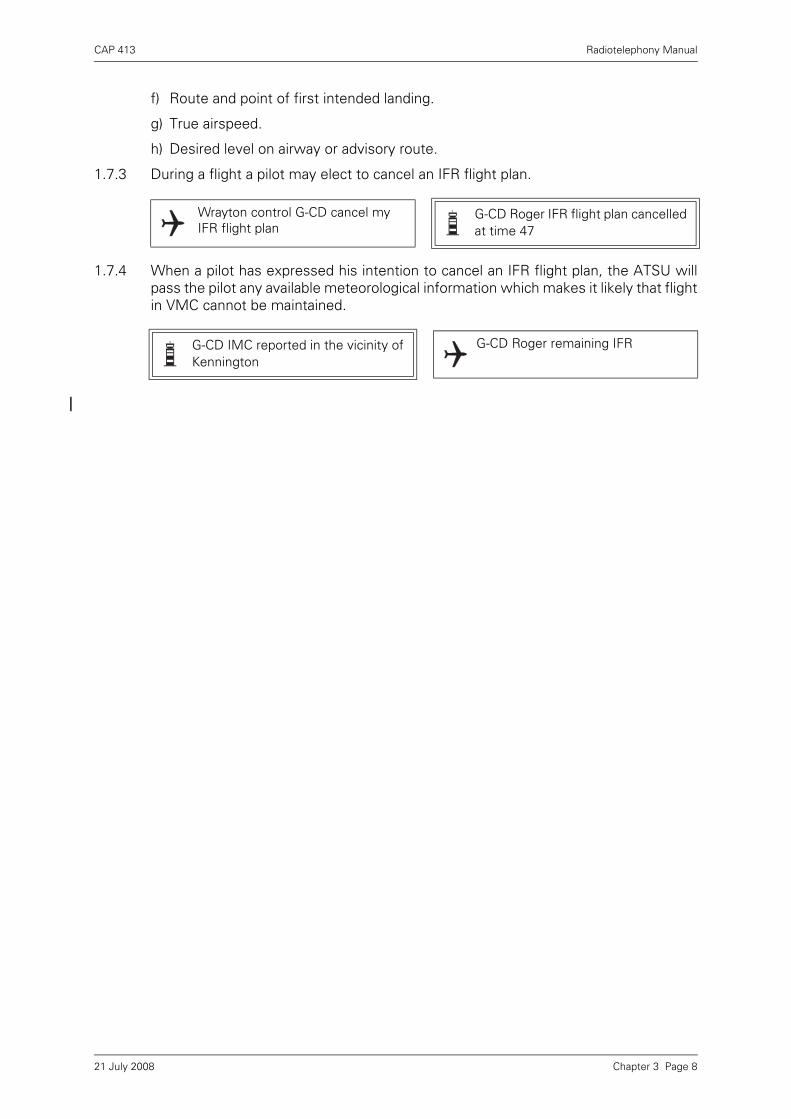
CAP 413 Radiotelephony Manual
f) Route and point of first intended landing.
g) True airspeed.
h) Desired level on airway or advisory route.
1.7.3 During a flight a pilot may elect to cancel an IFR flight plan.
1.7.4 When a pilot has expressed his intention to cancel an IFR flight plan, the ATSU willpass the pilot any available meteorological information which makes it likely that flightin VMC cannot be maintained.
Wrayton control G-CD cancel my IFR flight plan
G-CD Roger IFR flight plan cancelled at time 47
G-CD IMC reported in the vicinity of Kennington
G-CD Roger remaining IFR
Chapter 3 Page 821 July 2008
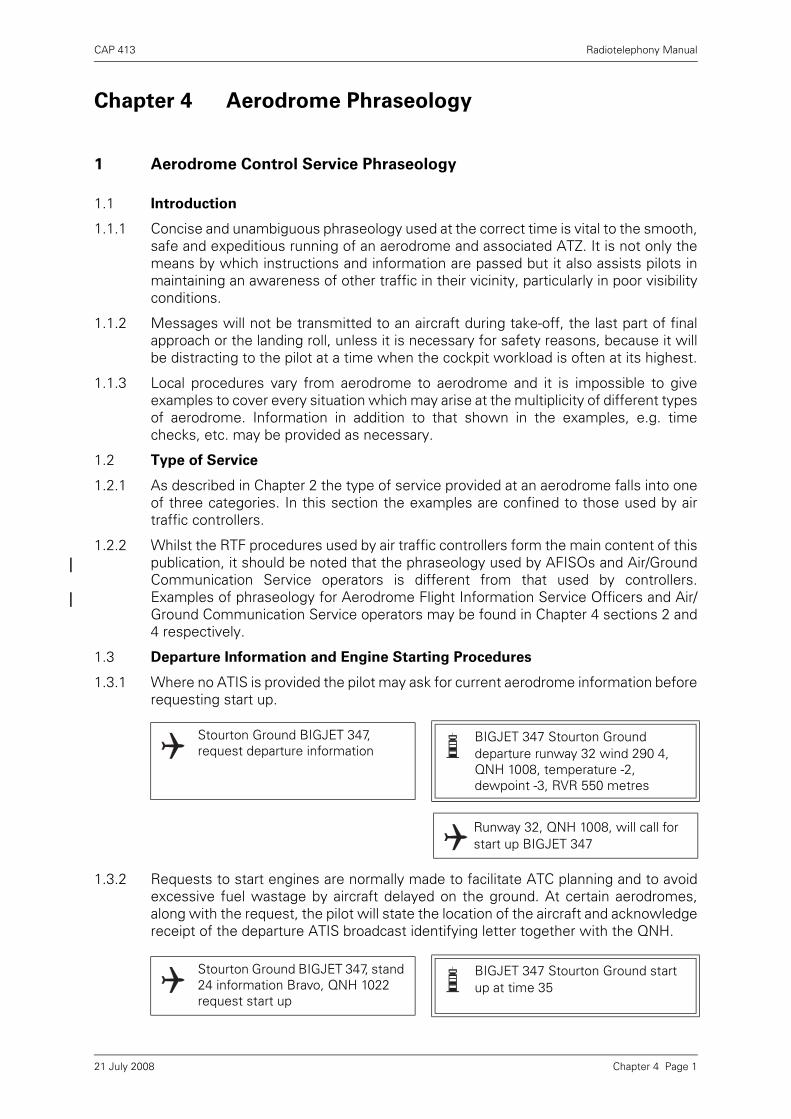
CAP 413 Radiotelephony Manual
Chapter 4 Aerodrome Phraseology
1 Aerodrome Control Service Phraseology
1.1 Introduction
1.1.1 Concise and unambiguous phraseology used at the correct time is vital to the smooth,safe and expeditious running of an aerodrome and associated ATZ. It is not only themeans by which instructions and information are passed but it also assists pilots inmaintaining an awareness of other traffic in their vicinity, particularly in poor visibilityconditions.
1.1.2 Messages will not be transmitted to an aircraft during take-off, the last part of finalapproach or the landing roll, unless it is necessary for safety reasons, because it willbe distracting to the pilot at a time when the cockpit workload is often at its highest.
1.1.3 Local procedures vary from aerodrome to aerodrome and it is impossible to giveexamples to cover every situation which may arise at the multiplicity of different typesof aerodrome. Information in addition to that shown in the examples, e.g. timechecks, etc. may be provided as necessary.
1.2 Type of Service
1.2.1 As described in Chapter 2 the type of service provided at an aerodrome falls into oneof three categories. In this section the examples are confined to those used by airtraffic controllers.
1.2.2 Whilst the RTF procedures used by air traffic controllers form the main content of thispublication, it should be noted that the phraseology used by AFISOs and Air/GroundCommunication Service operators is different from that used by controllers.Examples of phraseology for Aerodrome Flight Information Service Officers and Air/Ground Communication Service operators may be found in Chapter 4 sections 2 and4 respectively.
1.3 Departure Information and Engine Starting Procedures
1.3.1 Where no ATIS is provided the pilot may ask for current aerodrome information beforerequesting start up.
1.3.2 Requests to start engines are normally made to facilitate ATC planning and to avoidexcessive fuel wastage by aircraft delayed on the ground. At certain aerodromes,along with the request, the pilot will state the location of the aircraft and acknowledgereceipt of the departure ATIS broadcast identifying letter together with the QNH.
Stourton Ground BIGJET 347, request departure information
BIGJET 347 Stourton Ground departure runway 32 wind 290 4, QNH 1008, temperature -2, dewpoint -3, RVR 550 metres
Runway 32, QNH 1008, will call for start up BIGJET 347
Stourton Ground BIGJET 347, stand 24 information Bravo, QNH 1022 request start up
BIGJET 347 Stourton Ground start up at time 35
Chapter 4 Page 121 July 2008
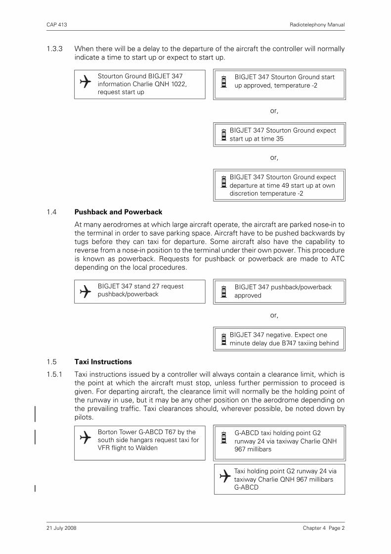
CAP 413 Radiotelephony Manual
1.3.3 When there will be a delay to the departure of the aircraft the controller will normallyindicate a time to start up or expect to start up.
or,
or,
1.4 Pushback and Powerback
At many aerodromes at which large aircraft operate, the aircraft are parked nose-in tothe terminal in order to save parking space. Aircraft have to be pushed backwards bytugs before they can taxi for departure. Some aircraft also have the capability toreverse from a nose-in position to the terminal under their own power. This procedureis known as powerback. Requests for pushback or powerback are made to ATCdepending on the local procedures.
or,
1.5 Taxi Instructions
1.5.1 Taxi instructions issued by a controller will always contain a clearance limit, which isthe point at which the aircraft must stop, unless further permission to proceed isgiven. For departing aircraft, the clearance limit will normally be the holding point ofthe runway in use, but it may be any other position on the aerodrome depending onthe prevailing traffic. Taxi clearances should, wherever possible, be noted down bypilots.
Stourton Ground BIGJET 347 information Charlie QNH 1022, request start up
BIGJET 347 Stourton Ground start up approved, temperature -2
BIGJET 347 Stourton Ground expect start up at time 35
BIGJET 347 Stourton Ground expect departure at time 49 start up at own discretion temperature -2
BIGJET 347 stand 27 request pushback/powerback
BIGJET 347 pushback/powerback approved
BIGJET 347 negative. Expect one minute delay due B747 taxiing behind
Borton Tower G-ABCD T67 by the south side hangars request taxi for VFR flight to Walden
G-ABCD taxi holding point G2 runway 24 via taxiway Charlie QNH 967 millibars
Taxi holding point G2 runway 24 via taxiway Charlie QNH 967 millibars G-ABCD
Chapter 4 Page 221 July 2008

CAP 413 Radiotelephony Manual
G-ABCD request surface wind
G-CD surface wind 220 6
G-CD request runway 14
G-CD follow the Seneca coming from your left taxi holding point B1 runway 14
Following the Seneca from the left, taxi holding point B1 runway 14. G-CD
Borton Tower G-ABCD T67 at the fuel station VFR to Walden request taxi
G-CD runway 06 QNH 1008 taxi holding point B2 runway 14 via taxiway Alpha
QNH 1008 G-CD request taxiway Bravo, and backtrack runway 06
G-CD taxi holding point H1 runway 06 via taxiway Bravo
Taxi holding point H1 runway 06 via taxiway Bravo G-CD
Borton Tower G-ABCD at the fuel station request taxi to flying club
G-CD taxi holding point A1 runway 24 via Charlie
Taxi holding point A1 runway 24 via Charlie G-CD
G-CD holding point A1 runway 24 request cross
G-CD negative. Hold position.
Holding G-CD
Chapter 4 Page 321 July 2008

CAP 413 Radiotelephony Manual
1.5.2 When passing taxi instructions that will position an aircraft to cross a runway thecontroller may, optionally, insert the phrase ‘hold short of’ prior to the runwaydesignator. This phrase is intended to reinforce the need to stop at the holding point.
1.5.3 Where an ATIS broadcast is established the controller does not need to passdeparture information to the pilot when giving taxi instructions. He will, however,check that the aircraft is in possession of the latest QNH.
1.6 Pre-Departure Manoeuvring
1.6.1 Meticulous care has been taken to ensure that the phraseology which is to beemployed during the pre-departure manoeuvres cannot be interpreted as a take-offclearance. This is to avoid any misunderstanding in the granting or acknowledgementof take-off clearances and the serious consequences that could result.
G-CD taxi to the flying club, via A1 cross runway 24 report vacated
Taxi to the flying club cross runway 24 via A1 will report vacated G-CD
G-CD runway vacated
G-CD
NOTES: 1 Instruction to report vacated may be omitted when aerodrome controlhas continuous sight of the aircraft crossing.
2 For helicopters the phrase “Air-taxi....” may be used in place of “Taxi....”.
BIGJET 347 taxi holding point C3, hold short of runway 36
Taxi holding point C3 hold short of runway 36, BIGJET 347
BIGJET 347 cross runway 36, taxi holding point A1, hold short of runway 09
Cross runway 36, taxi holding point A1, hold short of runway 09, BIGJET 347
BIGJET 347 information Bravo, QNH 1020 request taxi
BIGJET 347, now information Charlie, new QNH 1021, after the B747 passing left to right taxi holding point A1 runway 28
QNH 1021, after B747 left to right taxi holding point A1 runway 28 BIGJET 347
Chapter 4 Page 421 July 2008

CAP 413 Radiotelephony Manual
1.6.2 At busy aerodromes with a separate ground and tower function, aircraft are usuallytransferred to the tower frequency at or approaching the holding point.
1.6.3 Many types of aircraft carry out engine checks prior to departure and are not alwaysready for take-off when they reach the holding point.
1.6.4 When line-up will take place at a position other than for a full-length runway departurethe intermediate 'Holding Point' designator shall be included in the line-up instruction.Controllers may include the runway ‘Holding Point’ designator in any other line-upinstruction when considered necessary.
1.6.5 For reason of expedition, a controller may wish to line-up an aircraft for departurebefore conditions allow take-off.
1.7 Take-Off Clearance
1.7.1 Except in cases of emergency, messages will not be transmitted to an aircraft in theprocess of taking off or in the final stages of an approach and landing.
1.7.2 Controllers will use the following phraseology for take off.
NOTE: The surface wind will be passed if there is a significant difference to thatalready passed.
1.7.3 A take-off clearance shall be issued separately from any other clearance message.
BIGJET 347 contact Tower 118.9 Tower 118.9 BIGJET 347
G-CD report ready for departure Wilco G-CD
G-CD ready for departure G-CD line up
Line up G-CD
G-CD, ready for departure G-CD, via C2 line-up runway 28
G-CD, line-up via C2 runway 28
BIGJET 347 via holding point A1 line-up and wait runway 26, one aircraft to depart before you from holding point A2
Via holding point A1 line-up and wait runway 26, number two for departure, BIGJET 347
G-CD cleared for take-off Cleared for take-off G-CD
Chapter 4 Page 521 July 2008
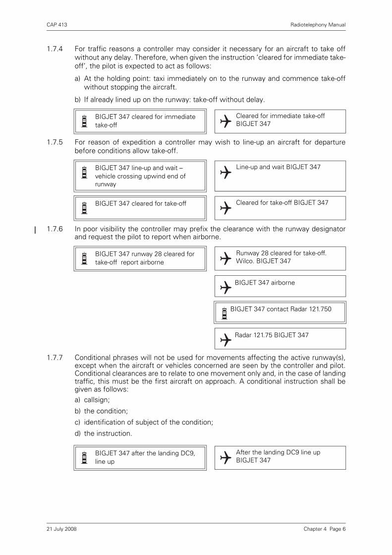
CAP 413 Radiotelephony Manual
1.7.4 For traffic reasons a controller may consider it necessary for an aircraft to take offwithout any delay. Therefore, when given the instruction ‘cleared for immediate take-off’, the pilot is expected to act as follows:
a) At the holding point: taxi immediately on to the runway and commence take-offwithout stopping the aircraft.
b) If already lined up on the runway: take-off without delay.
1.7.5 For reason of expedition a controller may wish to line-up an aircraft for departurebefore conditions allow take-off.
1.7.6 In poor visibility the controller may prefix the clearance with the runway designatorand request the pilot to report when airborne.
1.7.7 Conditional phrases will not be used for movements affecting the active runway(s),except when the aircraft or vehicles concerned are seen by the controller and pilot.Conditional clearances are to relate to one movement only and, in the case of landingtraffic, this must be the first aircraft on approach. A conditional instruction shall begiven as follows:a) callsign;
b) the condition;
c) identification of subject of the condition;
d) the instruction.
BIGJET 347 cleared for immediate take-off
Cleared for immediate take-off BIGJET 347
BIGJET 347 line-up and wait – vehicle crossing upwind end of runway
Line-up and wait BIGJET 347
BIGJET 347 cleared for take-off Cleared for take-off BIGJET 347
BIGJET 347 runway 28 cleared for take-off report airborne
Runway 28 cleared for take-off. Wilco. BIGJET 347
BIGJET 347 airborne
BIGJET 347 contact Radar 121.750
Radar 121.75 BIGJET 347
BIGJET 347 after the landing DC9, line up
After the landing DC9 line up BIGJET 347
Chapter 4 Page 621 July 2008

CAP 413 Radiotelephony Manual
1.7.8 When several runways are in use and/or there is any possibility that the pilot may beconfused as to which one to use, the runway number will be stated prior to theclearance.
1.7.9 Local departure instructions may be given prior to the take-off clearance. Suchinstructions are normally given to ensure separation between aircraft operating in thevicinity of the aerodrome.
1.7.10 Revised clearances and post departure instructions for aircraft on the runway or at theholding position shall be prefixed with an instruction to hold position.
1.7.11 Due to unexpected traffic developments or a departing aircraft taking longer to take-off than anticipated, it is occasionally necessary to rescind the take-off clearance orquickly free the runway for landing traffic.
BIGJET 347 runway 09 left cleared for take-off
Runway 09 left cleared for take-off BIGJET 347
BIGJET 347 Hold position, after departure climb straight ahead to altitude 2500 feet QNH 1014 before turning right
BIGJET 347 Holding, after departure climb straight ahead to altitude 2500 feet, QNH 1014 before turning right.
BIGJET 347 Cleared for take-off
Cleared for take-off, BIGJET 347
G-CD, after departure request right turn
G-CD, Hold position, right turn approved
G-CD, Holding, right turn approved
G-CD, Cleared for take-off
Cleared for take-off, G-CD
BIGJET 347 take-off immediately or vacate runway
Taking-off BIGJET 347
BIGJET 347 take-off immediately or hold at the holding point
Holding BIGJET 347
Chapter 4 Page 721 July 2008

CAP 413 Radiotelephony Manual
1.7.12 When an aircraft is about to take-off or has commenced the take-off roll, and it isnecessary that the aircraft should abandon take-off, the aircraft will be instructed tocancel take-off or stop immediately; these instructions will be repeated.
1.7.13 When a pilot abandons take-off he should, as soon as practicable, inform the towerthat he is doing so. Likewise, as soon as practicable, he should inform the tower ofthe reasons for abandoning take-off if applicable, and request further manoeuvringinstructions.
1.8 Aerodrome Traffic Circuit
1.8.1 Designated Positions in the Traffic Circuit
G-CD hold position, cancel take-off I say again cancel take-off, acknowledge
Holding G-CD
BIGJET 347 stop immediately I say again BIGJET 347 stop immediately, acknowledge
Stopping BIGJET 347
BIGJET 347 stopping BIGJET 347
BIGJET 347 request backtrack for another departure
BIGJET 347 backtrack approved
Figure 1 Designated positions in the traffic circuit
RUNWAY IN USE
SURFACE WIND
LIV
E S
IDE
DE
AD
SID
E
4 miles or lessBeyond 4 miles
Chapter 4 Page 821 July 2008

CAP 413 Radiotelephony Manual
Typical Left-Hand Circuit
NOTE 1: For light aircraft operations, circuit dimensions may be reduced but the relativeRTF reporting points are maintained.
NOTE 2: For details of the standard overhead joining procedure see Aerodrome TrafficCircuit (Chapter 4 Paragraph 1.8) and RTF Reports at Unattended Aerodromes(Chapter 4 Paragraph 6.1).
1.8.2 Requests for circuit-joining instructions should be made in sufficient time for aplanned entry into the circuit taking other traffic into account. Where ATIS isestablished, receipt of the broadcast should be acknowledged in the initial call to anaerodrome. When the traffic circuit is a right-hand pattern it shall be specified. A left-hand pattern need not be specified although it is essential to do so when the circuitdirection is variable.
1.8.3 In some circumstances, an aircraft may be instructed to complete a standardoverhead join which comprises the following:
a) Overfly at 2000 ft above Aerodrome Elevation.
b) If not already known, determine the circuit direction from the signals square, othertraffic or windsock.
c) Descend on the ‘dead side’ to circuit height.
d) Join the circuit by crossing the upwind end of the runway at circuit height.
e) Position downwind.
NOTE: Aerodromes with overhead joins at variance to the above standard procedurewill notify such differences.
Position 1 Aircraft reports on 'Downwind' leg.
Position 2 Aircraft reports 'Late downwind' if it is on the downwind leg, has been unable to report 'Downwind' and has passed the downwind end of the runway.
Position 3 Aircraft reports 'Base' leg (if required).
Position 4 Aircraft reports ‘Final’. Clearance to land issued here.
Position 5 Aircraft reports 'Long final' (between 8 and 4 miles) when aircraft is on a straight in approach.
Walden Tower G-ABCD request join G-ABCD Walden Tower pass your message
G-ABCD T67 10 miles south altitude 2500 feet Wessex 1008
G-CD join righthand downwind runway 27 height 1000 feet QFE 1006
Join righthand downwind runway 27 height 1000 feet QFE 1006 G-CD
Chapter 4 Page 921 July 2008
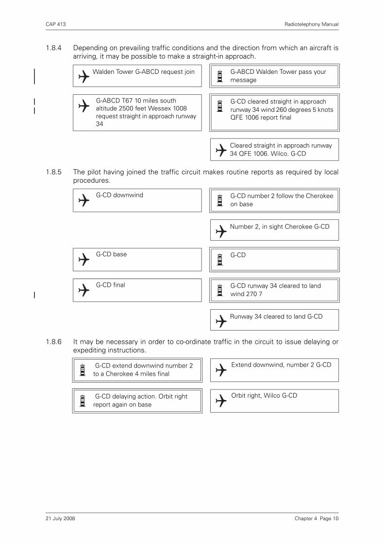
CAP 413 Radiotelephony Manual
1.8.4 Depending on prevailing traffic conditions and the direction from which an aircraft isarriving, it may be possible to make a straight-in approach.
1.8.5 The pilot having joined the traffic circuit makes routine reports as required by localprocedures.
1.8.6 It may be necessary in order to co-ordinate traffic in the circuit to issue delaying orexpediting instructions.
Walden Tower G-ABCD request join G-ABCD Walden Tower pass your message
G-ABCD T67 10 miles south altitude 2500 feet Wessex 1008 request straight in approach runway 34
G-CD cleared straight in approach runway 34 wind 260 degrees 5 knots QFE 1006 report final
Cleared straight in approach runway 34 QFE 1006. Wilco. G-CD
G-CD downwind G-CD number 2 follow the Cherokee on base
Number 2, in sight Cherokee G-CD
G-CD base G-CD
G-CD final G-CD runway 34 cleared to land wind 270 7
Runway 34 cleared to land G-CD
G-CD extend downwind number 2 to a Cherokee 4 miles final
Extend downwind, number 2 G-CD
G-CD delaying action. Orbit right report again on base
Orbit right, Wilco G-CD
Chapter 4 Page 1021 July 2008

CAP 413 Radiotelephony Manual
1.8.7 In order to save taxiing time when flying training in the traffic circuit pilots may wishto carry out a ‘touch and go’, i.e. the aircraft lands, continues rolling and takes-off,without stopping.
or,
1.8.8 It is helpful for circuit management purposes if a controller is informed when anaircraft which has been engaged in multiple approaches is on his last circuit.
1.9 Final Approach and Landing
1.9.1 A ‘final’ report is made when an aircraft has turned onto final approach. If the turn onis made at a distance greater than 4 nm from touchdown a ‘long final’ report is made.The landing/touch and go/low approach clearance will include the runway designation.
G-CD downwind touch and go G-CD report final
G-CD final
G-CD runway 34 cleared touch and go surface wind calm
Runway 34 cleared touch and go G-CD
G-CD unable to approve due traffic make full stop landing runway 34 cleared to land surface wind calm
Runway 34 cleared to land G-CD
G-CD downwind full stop G-CD report final
G-CD final G-CD runway 34 cleared to land surface wind 270 7
Runway 34 cleared to land G-CD
BIGJET 347 long final BIGJET 347 report final surface wind 260 18
Wilco BIGJET 347
Chapter 4 Page 1121 July 2008

CAP 413 Radiotelephony Manual
NOTE: Where established, an ‘outer marker’ instead of a ‘final’ report may be made.
1.9.2 The runway may be obstructed when the aircraft makes its ‘final’ report at 4 nm orless from touchdown but is expected to be available in good time for the aircraft tomake a safe landing. On these occasions, the controller will delay landing clearance.
The controller may or may not explain why the landing clearance has been delayedbut the instruction to ‘continue’ IS NOT an invitation to land and the pilot must waitfor landing clearance or initiate a missed approach (see Chapter 4, paragraph 1.10.3).
1.9.3 A landing aircraft may be permitted to touch down before a preceding landing aircrafthas vacated the runway provided that:
a) the runway is long enough to allow safe separation between the two aircraft andthere is no evidence to indicate that braking may be adversely affected;
b) it is during daylight hours;
c) the preceding landing aircraft is not required to backtrack in order to vacate therunway;
d) the controller is satisfied that the landing aircraft will be able to see the precedingaircraft which has landed, clearly and continuously, until it has vacated the runway;and
e) the pilot of the following aircraft is warned. (Responsibility for ensuring adequateseparation rests with the pilot of the following aircraft.)
1.9.4 A pilot may request to fly past the control tower or other observation point for thepurpose of visual inspection from the ground.
1.9.5 If the low pass is made for the purpose of observing the undercarriage, one of thefollowing replies could be used to describe its condition but these examples are notexhaustive:
a) landing gear appears down;
b) right (or left, or nose) wheel appears up (or down);
BIGJET 347 final
BIGJET 347 runway 28 cleared to land wind 270 20
Runway 28 cleared to land BIGJET 347
G-CD final G-CD continue approach wind 270 5
Continue approach G-CD
BIGJET 347, runway 28, land after the B737, wind calm
Land after the B737 BIGJET 347
Chapter 4 Page 1221 July 2008

CAP 413 Radiotelephony Manual
c) wheels appear up;
d) right (or left, or nose) wheel does not appear up (or down).
1.9.6 For training purposes, a pilot may request permission to make an approach along, orparallel to the runway, without landing.
1.10 Missed Approach
1.10.1 Instructions to carry out a missed approach may be given to avert an unsafe situation.When a missed approach is initiated cockpit workload is inevitably high. Anytransmissions to aircraft going around shall be brief and kept to a minimum.
1.10.2 An aircraft on an instrument approach is to carry out the published missed approachprocedure and an aircraft operating VFR is to continue into the normal traffic circuitunless instructions are issued to the contrary.
1.10.3 In the event of missed approach being initiated by the pilot, the phrase ‘going around’shall be used.
1.10.4 At military aerodromes ‘GO AROUND’ is also employed to instruct an aircraft to flyanother circuit. Unless otherwise instructed, circuit height should be maintained (orregained) and a ‘Deadside’ call made before turning Crosswind to report Downwind.
1.11 Runway Vacating and Communicating After Landing
1.11.1 Unless absolutely necessary, controllers will not give taxi instructions to pilots untilthe landing roll is complete. Unless otherwise advised, pilots should remain on towerfrequency until the runway is vacated.
BIGJET 347 request low approach for training
BIGJET 347 cleared low approach runway 28 not below 400 feet above threshold elevation report final
Cleared low approach runway 28 not below 400 feet above threshold elevation Wilco BIGJET 347
BIGJET 347 go around I say again go around acknowledge
Going around BIGJET 347
G-CD going around G-CD Roger
BIGJET 347 vacate left Vacate left BIGJET 347
BIGJET 347 when vacated contact Ground 118.350
When vacated Ground 118.350 BIGJET 347
Kennington Ground BIGJET 347 runway vacated
BIGJET 347 Kennington Ground taxi to Stand 27 via taxiway Alpha
Chapter 4 Page 1321 July 2008

CAP 413 Radiotelephony Manual
1.12 Essential Aerodrome Information
Essential Aerodrome Information is information regarding the manoeuvring area andits associated facilities which is necessary to ensure the safe operation of aircraft.Essential Aerodrome Information is passed to aircraft whenever possible prior tostart-up or taxi and prior to the commencement of final approach.
Taxi to Stand 27 via taxiway Alpha BIGJET 347
G-CD taxi to the end report runway vacated
Taxi to the end, Wilco G-CD
G-CD runway vacated
G-CD taxi to the flying club
Taxi to the flying club G-CD
BIGJET 347 caution construction work at the end of Stand 37
... caution work in progress ahead north side of taxiway Alpha
... caution centre line taxiway lighting unserviceable
... caution PAPIs runway 27 unserviceable
... caution large flock of birds north of runway 27 near centre taxiway
... message from aerodrome authority, fire and rescue services reduced. The aerodrome can only accept aircraft up to and including category (number)
Chapter 4 Page 1421 July 2008
CAP 413 Radiotelephony Manual
2 Aerodrome Flight Information Service Phraseology
2.1 Introduction
2.1.1 Concise and unambiguous phraseology used at the correct time is vital to the smooth,safe and expeditious running of an aerodrome and associated ATZ. It is not only themeans by which instructions and information are passed but it also assists pilots inmaintaining an awareness of other traffic in their vicinity, particularly in poor visibilityconditions.
2.1.2 Messages will not be transmitted to an aircraft during take-off, the last part of finalapproach or the landing roll, unless it is necessary for safety reasons, because it willbe distracting to the pilot at a time when the cockpit workload is often at its highest.
2.1.3 Local procedures vary from aerodrome to aerodrome and it is impossible to giveexamples to cover every situation which may arise at the multiplicity of different typesof aerodrome. Information in addition to that shown in the examples, e.g. timechecks, etc. may be provided as necessary.
2.2 Type of Service
2.2.1 As described in Chapter 2 the type of service provided at an aerodrome falls into oneof three categories. In this section the examples are confined to those used byAerodrome Flight Information Service Officers (AFISOs). Phraseology for air trafficcontrollers may be found in Chapter 4 paragraph 1 and that for Air/GroundCommunication Service Operators in Chapter 4 paragraph 5.
2.2.2 Whilst the RTF procedures used by air traffic controllers form the main content of thispublication it should be noted that the phraseology used by AFISOs is different fromthat used by controllers. An AFISO at an aerodrome provides a service to giveinformation useful for the safe and efficient conduct of flights in the AerodromeTraffic Zone. From the information received pilots will be able to decide theappropriate course of action to be taken to ensure the safety of flight. Generally, theAFISO is not permitted to issue instructions or advice to pilots of his own volition.However, in granting or refusing permission under Rule 35 and 36 of the Rules of theAir, AFISOs at aerodromes are permitted to pass instructions to vehicles andpersonnel operating on the manoeuvring area and information and instructions toaircraft moving on the apron and specific parts of the manoeuvring area. Elsewhereon the manoeuvring area and at all times in the air, information only shall be passedto pilots. Further details on the passing of instructions by AFISOs at aerodromes arecontained in CAP 410 Manual of Flight Information Services - Part B Aerodrome.
2.2.3 AFISOs are also permitted to pass messages on behalf of other agencies andinstructions from the aerodrome operator. If they do so, they will include the name ofthe agency so that pilots will be aware that the message comes from a legitimatesource, e.g. ‘Wrayton Control clears you to join ...’.
2.2.4 With the exception of issuing instructions to aircraft on the ground, AFISOs arereminded that the service they provide is an information service relating to the ATZand aerodrome. They must ensure that the information given to pilots is distinct andunambiguous, as pilots will use this information for the safe and efficient conduct oftheir flights.
2.2.5 An AFISO may request pilots to make position reports e.g.downwind, final etc. Theserequests do not have the status of instructions, although it is expected that mostpilots will comply.
Chapter 4 Page 1521 July 2008
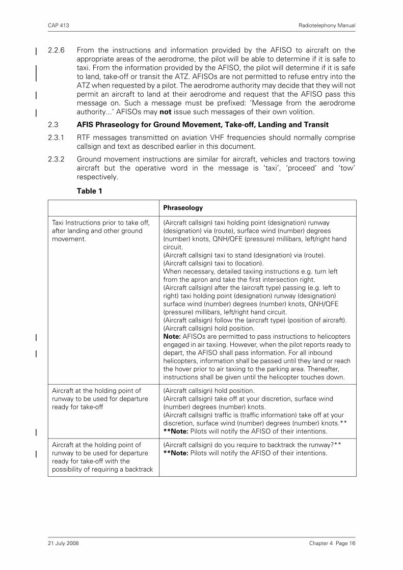
CAP 413 Radiotelephony Manual
2.2.6 From the instructions and information provided by the AFISO to aircraft on theappropriate areas of the aerodrome, the pilot will be able to determine if it is safe totaxi. From the information provided by the AFISO, the pilot will determine if it is safeto land, take-off or transit the ATZ. AFISOs are not permitted to refuse entry into theATZ when requested by a pilot. The aerodrome authority may decide that they will notpermit an aircraft to land at their aerodrome and request that the AFISO pass thismessage on. Such a message must be prefixed: ‘Message from the aerodromeauthority...’ AFISOs may not issue such messages of their own volition.
2.3 AFIS Phraseology for Ground Movement, Take-off, Landing and Transit
2.3.1 RTF messages transmitted on aviation VHF frequencies should normally comprisecallsign and text as described earlier in this document.
2.3.2 Ground movement instructions are similar for aircraft, vehicles and tractors towingaircraft but the operative word in the message is ‘taxi’, ‘proceed’ and ‘tow’respectively.
Table 1
Phraseology
Taxi Instructions prior to take off, after landing and other ground movement.
(Aircraft callsign) taxi holding point (designation) runway (designation) via (route), surface wind (number) degrees (number) knots, QNH/QFE (pressure) millibars, left/right hand circuit.(Aircraft callsign) taxi to stand (designation) via (route).(Aircraft callsign) taxi to (location).When necessary, detailed taxiing instructions e.g. turn left from the apron and take the first intersection right.(Aircraft callsign) after the (aircraft type) passing (e.g. left to right) taxi holding point (designation) runway (designation) surface wind (number) degrees (number) knots, QNH/QFE (pressure) millibars, left/right hand circuit.(Aircraft callsign) follow the (aircraft type) (position of aircraft).(Aircraft callsign) hold position.Note: AFISOs are permitted to pass instructions to helicopters engaged in air taxiing. However, when the pilot reports ready to depart, the AFISO shall pass information. For all inbound helicopters, information shall be passed until they land or reach the hover prior to air taxiing to the parking area. Thereafter, instructions shall be given until the helicopter touches down.
Aircraft at the holding point of runway to be used for departure ready for take-off
(Aircraft callsign) hold position.(Aircraft callsign) take off at your discretion, surface wind (number) degrees (number) knots.(Aircraft callsign) traffic is (traffic information) take off at your discretion, surface wind (number) degrees (number) knots.****Note: Pilots will notify the AFISO of their intentions.
Aircraft at the holding point of runway to be used for departure ready for take-off with the possibility of requiring a backtrack
(Aircraft callsign) do you require to backtrack the runway?****Note: Pilots will notify the AFISO of their intentions.
Chapter 4 Page 1621 July 2008
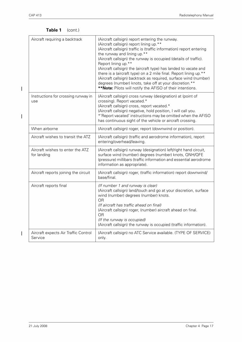
CAP 413 Radiotelephony Manual
Aircraft requiring a backtrack (Aircraft callsign) report entering the runway.(Aircraft callsign) report lining up.**(Aircraft callsign) traffic is (traffic information) report entering the runway and lining up.**(Aircraft callsign) the runway is occupied (details of traffic). Report lining up.**(Aircraft callsign) the (aircraft type) has landed to vacate and there is a (aircraft type) on a 2 mile final. Report lining up.**(Aircraft callsign) backtrack as required, surface wind (number) degrees (number) knots, take off at your discretion.****Note: Pilots will notify the AFISO of their intentions.
Instructions for crossing runway in use
(Aircraft callsign) cross runway (designation) at (point of crossing). Report vacated.*(Aircraft callsign) cross, report vacated.*(Aircraft callsign) negative, hold position, I will call you.*‘Report vacated’ instructions may be omitted when the AFISO has continuous sight of the vehicle or aircraft crossing.
When airborne (Aircraft callsign) roger, report (downwind or position).
Aircraft wishes to transit the ATZ (Aircraft callsign) (traffic and aerodrome information), report entering/overhead/leaving.
Aircraft wishes to enter the ATZ for landing
(Aircraft callsign) runway (designation) left/right hand circuit, surface wind (number) degrees (number) knots, QNH/QFE (pressure) millibars (traffic information and essential aerodrome information as appropriate).
Aircraft reports joining the circuit (Aircraft callsign) roger, (traffic information) report downwind/ base/final.
Aircraft reports final (If number 1 and runway is clear)(Aircraft callsign) land/touch and go at your discretion, surface wind (number) degrees (number) knots.OR(If aircraft has traffic ahead on final) (Aircraft callsign) roger, (number) aircraft ahead on final.OR(If the runway is occupied) (Aircraft callsign) the runway is occupied (traffic information).
Aircraft expects Air Traffic Control Service
(Aircraft callsign) no ATC Service available. (TYPE OF SERVICE) only.
Table 1 (cont.)
Chapter 4 Page 1721 July 2008

CAP 413 Radiotelephony Manual
2.3.3 Examples of typical AFISO/Pilot RTF exchanges are detailed below.
at the holding point...
G-ABCD, request taxi G-CD, taxi holding point C2, runway 06 via taxiway C, surface wind 060 10 knots, QNH 998 millibars, left hand circuit
Roger, taxi to holding point C2, runway 06 via taxiway C, QNH 998 millibars G-CD
G-CD, C2 Ready for departure G-CD, Hold position
G-CD, Holding
G-CD, Take-off at your discretion, surface wind 270 degrees 15 knots
G-CD, Taking off
G-CD, Traffic is a Cessna 172 base leg, take off at your discretion, surface wind 270 15
G-CD, Taking off
G-CD, Via C2 take-off at your discretion, surface wind 270 15
G-CD, Via C2 taking off
G-CD, Do you require to backtrack the runway?
G-CD, Affirm
G-CD, Traffic is a Cessna 172 base leg, via C2 report entering the runway and lining up
G-CD, Holding, wilco
G-CD, Entering runway 27 G-CD, Roger
G-CD, Lining up runway 27
G-CD, Take off at your discretion, surface wind 270 15
Chapter 4 Page 1821 July 2008

CAP 413 Radiotelephony Manual
In the circuit...
When the runway is available...
After landing...
G-CD, Taking off
G-CD, Report downwind
G-CD, Downwind to land G-CD, Roger, traffic is a Cessna 172 base leg, report final
Wilco G-CD
G-CD, Final G-CD, Roger, Cessna 172 ahead on final
Roger G-CD
G-CD, Land at your discretion, surface wind 050 10 knots
Roger G-CD
G-CD, after the Cessna 172 taxiing right to left, taxi to the aero club, via taxiway C
Roger, after the Cessna 172, taxi to the aero club, via taxiway C G-CD
Chapter 4 Page 1921 July 2008
CAP 413 Radiotelephony Manual
3 Aerodrome Phraseology for Helicopters
3.1 Introduction
3.1.1 Rotary-wing flight characteristics mean that helicopter operations at aerodromes candiffer significantly from fixed-wing operations. This section describes standardphraseology and procedures to address the different requirements for helicopterlifting, taxiing, taking-off and landing (including the approach and departure phases),particularly at aerodromes where rotary-wing and fixed-wing operations areintegrated.
3.1.2 Standard phraseology should be used in all situations for which it is specified. Whenstandardised phraseology cannot serve an intended transmission, plain languageshould be used. The use of plain language may further assist when describing rotary-wing aircraft manoeuvres. Care should be exercised to ensure that all parties involvedachieve clear understanding.
3.1.3 The phraseology described in this section is intended for general use. However, theexamples of taxiing phraseology describe communications specific to aerodromes atwhich ATC or AFIS is provided. Phraseology examples for take-off and landing arespecific to communications at aerodromes with ATC.
3.2 Helicopter Callsigns
3.2.1 Aircraft callsigns to be used are described in Chapter 2 paragraph 1.8. Provision ismade for the name of the aircraft manufacturer, or the aircraft model, to be usedbefore the aircraft registration (in full or abbreviated form). If considered appropriate,the pilot or ATSU may replace manufacturer’s name or aircraft model with the term‘Helicopter’ where this may benefit the ATSU or other aircraft (see phraseologyexamples paragraphs 3.6.4 and 3.6.5).
3.3 Helicopter Phraseology for Taxiing
3.3.1 These procedures are for helicopters taxiing for departure, or after landing, or forgeneral manouevring on the aerodrome. Phraseology and procedures for specificmanouevring on the aerodrome, for example for training purposes, should bedescribed in local procedures.
3.3.2 The term ‘LIFT’ shall describe a manoeuvre where the helicopter gets airborne andenters a ‘HOVER’.
3.3.3 ‘HOVER’ describes a manoeuvre where the helicopter holds position whilst airbornein ground effect, waiting to proceed. Hover allows spot/axial turns (i.e. about thecentral axis of the helicopter). When required, further instructions shouldsubsequently be transmitted to permit the helicopter to proceed.
3.3.4 The term ‘AIR TAXI’ shall be used when it is necessary for a helicopter to proceed ata slow speed above the surface, normally below 20 knots and in ground effect (ICAO).
3.3.5 The instruction ‘GROUND TAXI’ shall be used for the movement of a helicopter, incontact with the surface of the aerodrome, under its own power. This could berequired for a helicopter fitted with wheels, to reduce rotor downwash (ICAO).
Table 2
Full callsign Abbreviation
Helicopter G-ABCD Helicopter CD
Chapter 4 Page 2021 July 2008

CAP 413 Radiotelephony Manual
3.3.6 An instruction to ‘TAXI’ leaves the pilot free to select the most appropriate method,either ground taxi or air taxi. Pilots and controllers should use the term AIR TAXI orGROUND TAXI when required to differentiate between air taxiing and ground taxiing(for helicopters equipped with wheels).
NOTE 1: Air taxiing helicopters at aerodromes where ATC and AFIS are provided willbe issued with detailed taxi routes and instructions as appropriate toprevent collisions with other aircraft and vehicles. Helicopters are expectedto follow procedures/routes on aerodromes appropriate to aeroplanesunless otherwise authorised.
NOTE 2: ATC and AFIS units will normally avoid issuing instructions that result intaxiing helicopters coming into close proximity with small aircraft orhelicopters and will normally give consideration to the effect of turbulencefrom taxiing helicopters on arriving and departing light aircraft (ICAO).
3.3.7 For a helicopter taxiing, the instruction ‘HOLD’ shall indicate a requirement to cometo a standstill.
3.3.7.1 A helicopter air taxiing and instructed to ‘HOLD’, may hold in the hover or may touchdown and hold on the ground at the pilot’s discretion. If touch down is not authorised,a helicopter may be instructed by the ATSU to ‘HOLD IN THE HOVER’.
3.3.7.2 A helicopter ground taxiing and instructed to ‘HOLD’ shall hold on the ground, unlessa hover manouevre is specifically authorised or requested by the ATS unit.
3.3.8 ATC and AFIS will normally avoid issuing a frequency change instruction to a single-pilot helicopter hovering or air taxiing. If required and whenever possible, controlinstructions from the next ATS unit will be relayed until the pilot is able to changefrequency (ICAO).
3.4 Helicopter Phraseology for Take-Off and Landing (ATC Only)
3.4.1 At aerodromes, helicopter take-offs and landings may not be restricted to designatedrunways or landing areas. With appropriate permission helicopters may take-off andland ay any location on the aerodrome. At aerodromes with an air traffic controlservice, all movements are subject to the permission of the ATC unit.
3.4.2 At aerodromes with air traffic control service, when helicopters land or take-off on themanoeuvring area, and within sight of the VCR the terms ‘CLEARED TO LAND’ and‘CLEARED FOR TAKE-OFF’ shall be used to authorise the manoeuvres.
3.4.3 At aerodromes with air traffic control service, when helicopters land or take-off atlocations not on the manoeuvring area (e.g. apron, maintenance area, sites adjacentthe aerodrome), or locations not in sight of the VCR, or unlit locations at night, theappropriate phrase ‘LAND AT YOUR DISCRETION’ or ‘TAKE-OFF AT YOURDISCRETION’ shall be used to authorise the manoeuvres. Relevant traffic informationon other aircraft (airborne or on the ground) shall also be passed.
3.4.4 The term ‘TOUCH DOWN’ shall be used to describe an aircraft (helicopter or fixed-wing) coming into contact with the surface in accordance with normal operation. Aclearance to land leaves the pilot of a helicopter free to either enter a low hover, or totouch down, as appropriate.
Chapter 4 Page 2121 July 2008

CAP 413 Radiotelephony Manual
3.5 Helicopter Taxiing Phraseology Examples (ATC and AFIS Only)
3.5.1 Taxi Instruction
3.5.2 Air Taxi Instruction (if required)
3.6 Helicopter Take-Off and Landing Phraseology Examples (ATC only)
3.6.1 Take-Off on the Runway
3.6.2 Landing on the Runway
3.6.3 Take-Off from a designated Helicopter Landing Area on the Manoeuvring Area
Borton Tower, G-ABCD, request TAXI for departure runway 06
G-ABCD, Borton Tower, TAXI holding point H1, runway 06, via taxiway Golf
TAXI holding point H1 runway 06 via taxiway Golf, G-ABCD
Note: The use of ‘taxi’ indicates the pilot is free to air taxi or ground taxi at his/her discretion
Borton Tower, G-ABCD, request AIR TAXI for departure runway 06
G-CD, Borton, AIR TAXI holding point H1, runway 06, via taxiway Golf
AIR TAXI holding point H1 runway 06 via taxiway Golf, G-CD
G-CD, ready for departure G-CD, Runway 06, CLEARED FOR TAKE-OFF
CLEARED FOR TAKE-OFF, G-CD
G-CD, final runway 06 G-CD, Runway 06, CLEARED TO LAND, surface wind 060 10
CLEARED TO LAND, G-CD
G-CD, ‘Area Whiskey’ ready for departure
G-CD, ‘Area Whiskey’ CLEARED FOR TAKE-OFF
CLEARED FOR TAKE-OFF, G-CD
Chapter 4 Page 2221 July 2008

CAP 413 Radiotelephony Manual
3.6.4 Landing at a designated Helicopter Landing Area on the Manoeuvring Area.
3.6.5 Take-Off from the Apron (or location not on the Manoeuvring Area) for a DirectDeparture (i.e. not following the visual circuit for departure).
3.6.6 Direct Arrival to the Apron (or location not on the Manoeuvring Area) for Landing.
G-ABCD, at the Power Station to land ‘Area Whisky’
G-CD, ‘Area Whisky’ CLEARED TO LAND, surface wind 060 10
CLEARED TO LAND, ‘Area Whisky’ G-CD
Borton Tower, Helicopter G-ABCD, beside the south side hangars ready for direct departure to Walden
Helicopter CD, Borton, direct departure, surface wind 060 10, QNH 997 millibars, no reported traffic, TAKE-OFF AT YOUR DISCRETION
TAKING-OFF, departing direct, QNH 997 millibars, Helicopter CD
Borton Tower, Helicopter G-ABCD, 5 miles east inbound to land Eastern Apron
Helicopter CD, Borton, route to the eastern apron via the Power Station, report at the Power Station wind 060 10 QNH 997 millibars, runway 06 in use
Route to Eastern Apron via the Power Sation, wilco, QNH 997 millibars, Helicopter CD
Helicopter CD, at the Power Station
Helicopter CD, traffic is a C172 taxiing from Stand 8 for taxiway B, LAND AT YOUR DISCRETION, surface wind 060 10
ROGER, Landing Eastern Apron, Helicopter CD
Chapter 4 Page 2321 July 2008

CAP 413 Radiotelephony Manual
4 Aerodrome Phraseology for Vehicles (ATC and AFIS only)
4.1 Introduction
4.1.1 The expeditious movement of vehicles plays an essential supporting role in theoperation of an aerodrome. Whenever possible the areas in which vehicles andaircraft operate are segregated. However, there are many occasions when vehiclesneed to move on the manoeuvring area either for maintenance purposes or in directsupport of aircraft operations.
4.1.2 Procedures governing the movement of vehicles vary widely from aerodrome toaerodrome, but certain factors to be taken into account when driving on an aerodromeare common to all:
a) in general, aircraft are by no means as manoeuvrable as ground vehicles;
b) the visibility from an aircraft cockpit for ground movement purposes is oftenrestricted compared with a vehicle.
Therefore when vehicles are operating in close proximity to aircraft, drivers should beextremely vigilant and comply with Rule 36/37 of the Rules of the Air and, ifapplicable, ATC instructions.
4.1.3 Correct RTF operating technique must be observed by all users. For all vehicles onthe movement area, it is important that a continuous listening watch is maintained,not only in case of further instructions or information from the tower, but also so thatdrivers can be aware of the movements, and intended movements, of other trafficthereby reducing the risk of confliction.
4.1.4 The examples that follow are applicable to air traffic controllers and AFISOs
only. Air/Ground Communication Service operators are not to pass instructions
and must use the phraseology they would use for the movement of aircraft on
the aerodrome.
4.2 Movement Instructions
4.2.1 Drivers on first call should identify themselves by their vehicle call sign, state theirposition and intended destination (and possibly required route).
4.2.2 If the controller is too busy he will reply ‘standby’. This means that the driver shouldwait until the controller calls back. The driver shall not proceed until permission isgiven.
4.2.3 When there is conflicting traffic the controller may reply ‘hold position’. This meansthat the driver shall not proceed until the controller calls back with permission. Allother replies should contain a clearly defined point to which the driver may proceed;this may or may not be the intended destination. If it is not the intended destinationdrivers must stop at this point and further permission shall be requested.
Ground Works 21 stand 27 request proceed to work in progress taxiway Hotel
Works 21 proceed to taxiway Hotel via Kilo and Alpha
Proceed to taxiway Hotel via Kilo and Alpha Works 21
Chapter 4 Page 2421 July 2008

CAP 413 Radiotelephony Manual
NOTE: The vehicle has only been cleared as far as the holding position to awaitrunway crossing clearance and permission to proceed to hangar 3.
4.2.4 Permission to proceed on the apron may include instructions to ensure safeoperations.
4.3 To Cross a Runway
4.3.1 Drivers should note carefully the position to which they may proceed, particularlywhere the intended route involves crossing a runway. Some aerodromes may haveprocedures that will allow vehicles to proceed to a holding point on the movementarea and then request runway crossing instructions. Under no circumstances shall adriver cross a runway unless positive permission has been given and
acknowledged. A runway vacated report should not be made until the vehicle (andtow) is clear of the designated runway area.
4.3.2 In order to prevent unauthorised runway incursions, when an ATS Unit issues aninstruction to cross a runway, the appropriate holding point designator shall beincluded in the instruction. A vehicle driver should query any instruction that identifiesa holding point designator inconsistent with the vehicle location, or the driver’srequest, before proceeding onto the runway.
Ground Tels 5 at Charlie 8 request proceed to hangar 3
Tels 5 proceed holding point C1 runway 14
Proceeding holding point C1 runway 14 Tels 5
Ground Tug 5 stand 21 request proceed to gate 26
Tug 5 after the BIGJET BAe 146 on your right has passed, proceed to stand 26, caution jet blast
After the BAe 146 has passed proceed stand 26, Tug 5
Ground Works 21 by the control tower request proceed to maintenance base
Works 21 proceed holding point A2 runway 32 via Alpha and Bravo
Proceeding holding point A2 runway 32 via Alpha and Bravo Works 21
Works 21 holding point A2 runway 32 request cross
Works 21 hold position
Holding Works 21
Chapter 4 Page 2521 July 2008

CAP 413 Radiotelephony Manual
4.3.3 If a vehicle is operating on the runway, it will be instructed to vacate the runway whenit is expected that an aircraft will be landing or taking off.
4.3.4 When a vehicle is moving on the movement area it may be necessary to inform thevehicle of a potentially dangerous situation and to tell it to stop.
4.4 Vehicles Towing Aircraft
Drivers of vehicles required to tow aircraft should not assume that the receivingstation is aware that an aircraft is to be towed. The performance and manoeuvrabilityof ground vehicles is obviously considerably reduced when towing aircraft and this istaken into account when instructions to such vehicles are issued. Therefore, in orderto avoid any confusion, and as an aid to identification, drivers should state the type,and where applicable the operator, of the aircraft to be towed in the first call.
Works 21 via A2 cross runway 32 proceed to maintenance base via
Foxtrot
Crossing via A2 runway 32 proceeding to maintenance base via Foxtrot Works 21
Works 21 vacate runway 27 take next right, report vacated
Vacate next right, Wilco Works 21
Works 21 runway 27 vacated
Works 21
Works 21 stop immediately aircraft crossing ahead
Stopping Works 21
Ground Tug 9 request tow BIGJET BAe 146 from stand 25 to maintenance hangar 3
Tug 9, tow from stand 25 to maintenance hangar 3 via taxiway Echo
Tow from stand 25 to maintenance hangar 3 via taxiway Echo, Tug 9
Chapter 4 Page 2621 July 2008

CAP 413 Radiotelephony Manual
5 Aerodrome Air/Ground Communication Service Phraseology
5.1 Introduction
5.1.1 Concise and unambiguous phraseology used at the correct time is vital to the smooth,safe and expeditious running of an aerodrome and associated ATZ. It is not only themeans by which information is passed but it also assists pilots in maintaining anawareness of other traffic in their vicinity, particularly in poor visibility conditions.
5.1.2 Messages will not be transmitted to an aircraft during take-off, the last part of finalapproach or the landing roll, unless it is necessary for safety reasons, because it willbe distracting to the pilot at a time when the cockpit workload is often at its highest.
5.1.3 Local procedures vary from aerodrome to aerodrome and it is impossible to giveexamples to cover every situation which may arise at the multiplicity of different typesof aerodrome. Information in addition to that shown in the examples, e.g. timechecks, etc. may be provided as necessary.
5.2 Type of Service
5.2.1 As described in Chapter 2 the type of service provided at an aerodrome falls into oneof three categories. In this section the examples are confined to those used by Air/Ground Communication Service operators.
5.2.2 Whilst the RTF procedures used by air traffic controllers and AFISOs form the maincontent of this publication it should be noted that the phraseology used by Air/GroundCommunication Service operators is different from that used by controllers andAFISOs. This section describes only the phraseology provided by AGCS operators anddetails of the service itself may be found in CAP 452 Aeronautical Radio StationOperator’s Guide on the CAA web site or from the CAA’s printers (Details can be foundon the inside cover of this publication). Phraseology for aerodrome air trafficcontrollers may be found in Chapter 4 paragraph 1 and that for AFISOs in Chapter 4paragraph 2.
5.2.3 An AGCS radio station operator is not necessarily able to view any part of theaerodrome or surrounding airspace. Traffic information provided by an AGCS radiostation operator is therefore based primarily on reports made by other pilots.Information provided by an AGCS radio station operator may be used to assist a pilotin making decisions, however, the safe conduct of the flight remains the pilot’sresponsibility.
5.3 Air/Ground Station Identification
Radio operators must ensure that the full callsign, including the suffix ‘RADIO’, isused in response to the initial call from an aircraft and on any other occasion that thereis doubt.
5.4 Phraseology and Examples
5.4.1 From time to time air traffic controllers and flight information service officers areinvited by aerodrome authorities to provide an Air/Ground Communication Service.They are permitted to do so in certain circumstances provided they hold a validCertificate of Competence (CA 1308). However, air traffic controllers, in particular,must appreciate that there is a considerable difference between the service theynormally provide and the Air/Ground Communication Service. Therefore they must becareful not to lapse into providing an air traffic control service.
5.4.2 Personnel providing an Air/Ground Communication Service must ensure that they donot pass a message which could be construed to be either an air traffic controlinstruction or an instruction issued by AFISOs for specific situations. Clearances
Chapter 4 Page 2721 July 2008
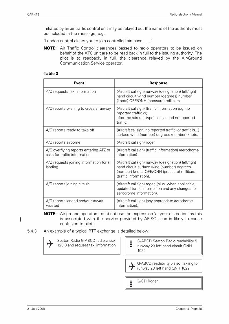
CAP 413 Radiotelephony Manual
initiated by an air traffic control unit may be relayed but the name of the authority mustbe included in the message, e.g:
‘London control clears you to join controlled airspace . . . ’
NOTE: Air Traffic Control clearances passed to radio operators to be issued onbehalf of the ATC unit are to be read back in full to the issuing authority. Thepilot is to readback, in full, the clearance relayed by the Air/GroundCommunication Service operator.
NOTE: Air ground operators must not use the expression ‘at your discretion’ as thisis associated with the service provided by AFISOs and is likely to causeconfusion to pilots.
5.4.3 An example of a typical RTF exchange is detailed below:
Table 3
Event Response
A/C requests taxi information (Aircraft callsign) runway (designation) left/right hand circuit wind number (degrees) number (knots) QFE/QNH (pressure) millibars.
A/C reports wishing to cross a runway (Aircraft callsign) (traffic information e.g. no reported traffic or, after the (aircraft type) has landed no reported traffic).
A/C reports ready to take off (Aircraft callsign) no reported traffic (or traffic is...) surface wind (number) degrees (number) knots.
A/C reports airborne (Aircraft callsign) roger
A/C overflying reports entering ATZ or asks for traffic information
(Aircraft callsign) (traffic information) (aerodrome information)
A/C requests joining information for a landing
(Aircraft callsign) runway (designation) left/right hand circuit surface wind (number) degrees (number) knots, QFE/QNH (pressure) millibars (traffic information).
A/C reports joining circuit (Aircraft callsign) roger, (plus, when applicable, updated traffic information and any changes to aerodrome information).
A/C reports landed and/or runway vacated
(Aircraft callsign) (any appropriate aerodrome information).
Seaton Radio G-ABCD radio check 123.0 and request taxi information
G-ABCD Seaton Radio readability 5 runway 23 left hand circuit QNH 1022
G-ABCD readability 5 also, taxiing for runway 23 left hand QNH 1022
G-CD Roger
Chapter 4 Page 2821 July 2008

CAP 413 Radiotelephony Manual
or,
or,
once Cherokee has landed and vacated
G-CD ready for departure G-CD roger. No reported traffic, surface wind 230 degrees 10 knots
Roger taking off G-CD
G-CD traffic is a Cherokee reported final, surface wind 230 degrees 10 knots
Roger taking off G-CD
Roger holding position G-CD
G-CD lining-up and taking off G-CD roger surface wind 230 degrees 10 knots
G-CD leaving the circuit to the west. Will report when re-joining
G-CD roger two other aircraft reported operating VFR to the west
Roger G-CD
Seaton Radio G-BCDA request traffic information
G-BCDA Seaton Radio pass your message
G-BCDA PA28 from Westbury to Millom position overhead Marlow, 1800 feet on QNH 1021, estimate Seaton at 15
G-DA, roger. Runway 23 is active left hand with a Cessna 172 reported downwind QNH 1022
QNH 1022 will report overhead G-DA
Chapter 4 Page 2921 July 2008

CAP 413 Radiotelephony Manual
or,
5.5 Offshore Communication Service
5.5.1 Introduction
Aeronautical radio stations located offshore on rigs, platforms and vessels provide anair-ground service to helicopters operating in the vicinity.
G-DA overhead at 15 will report leaving the frequency
G-DA roger
G-DA now leaving the ATZ changing to Wrayton information 124.75
G-DA roger
Seaton Radio G-ABCD 6 miles west of Seaton request joining information
G-CD Seaton runway 23 left hand, QFE 1021. Traffic is a Cessna 172 reported left base
Roger. Runway 23 left hand circuit, QFE 1021 G-CD
G-CD overhead joining for runway 23
G-CD roger no reported traffic
G-CD downwind G-CD roger no reported traffic
G-CD final G-CD roger surface wind 220 15. Traffic is a Cessna 172 reported lining up to depart
Roger G-CD
G-CD vacating left and returning to the club
G-CD roger
G-CD ready to cross runway 15 G-CD roger no reported traffic
Roger G-CD
Chapter 4 Page 3021 July 2008
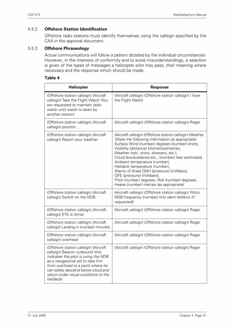
CAP 413 Radiotelephony Manual
5.5.2 Offshore Station Identification
Offshore radio stations must identify themselves using the callsign specified by theCAA in the approval document.
5.5.3 Offshore Phraseology
Actual communications will follow a pattern dictated by the individual circumstances.However, in the interests of conformity and to avoid misunderstandings, a selectionis given of the types of messages a helicopter pilot may pass, their meaning wherenecessary and the response which should be made.
Table 4
Helicopter Response
(Offshore station callsign) (Aircraft callsign) Take the Flight Watch (You are requested to maintain radio watch until watch is taken by another station)
(Aircraft callsign) (Offshore station callsign) I have the Flight Watch
(Offshore station callsign) (Aircraft callsign) position …
(Aircraft callsign) (Offshore station callsign) Roger
(Offshore station callsign) (Aircraft callsign) Report your weather
(Aircraft callsign) (Offshore station callsign) Weather (State the following information as appropriate) Surface Wind (number) degrees (number) knots, Visibility (distance) kilometres/metres, Weather (rain, snow, showers, etc.),Cloud few/scattered etc., (number) feet estimated, Ambient temperature (number), Helideck temperature (number), (Name of Area) QNH (pressure) (millibars),QFE (pressure) (millibars),Pitch (number) degrees: Roll (number) degrees: Heave (number) metres (as appropriate)
(Offshore station callsign) (Aircraft callsign) Switch on the NDB
(Aircraft callsign) (Offshore station callsign) Wilco NDB frequency (number) kHz ident (letters) (if requested)
(Offshore station callsign) (Aircraft callsign) ETA is (time)
(Aircraft callsign) (Offshore station callsign) Roger
(Offshore station callsign) (Aircraft callsign) Landing in (number) minutes
(Aircraft callsign) (Offshore station callsign) Roger
(Offshore station callsign) (Aircraft callsign) overhead
(Aircraft callsign) (Offshore station callsign) Roger
(Offshore station callsign) (Aircraft callsign) Beacon outbound (this indicates the pilot is using the NDB as a navigational aid to take him from overhead to a point where he can safely descend below cloud and return under visual conditions to the helideck)
(Aircraft callsign) (Offshore station callsign) Roger
Chapter 4 Page 3121 July 2008

CAP 413 Radiotelephony Manual
NOTE 1: The phrase 'Deck available (for landing)' replaces the previously usedphrase, 'Deck is clear for landing', in order to avoid any possible confusionwith a landing clearance that may be issued by an Air Traffic Control unit.For operational purposes, the two terms should be considered to have thesame meaning.
NOTE 2: Procedures for certain messages (e.g. when following the requirementsfor notification of the flight when there is no ATSU at the destination – seeAIP ENR 1.10), including the phraseology to be used, should be containedin the aircraft operator’s standard operating procedures and localoperating procedures. These messages are not air traffic servicemessages and are not reproduced in this document.
(Offshore station callsign) (Aircraft callsign) Is the deck available for landing?
(Aircraft callsign) (Offshore station callsign) Affirm Deck available (for landing) or Deck obstructed, expect (number) minutes delay, or Deck closed due to (reason), expect (number) minutes delay Note: Transmission of 'for landing' is optional
(Offshore station callsign) (Aircraft callsign) Ready for departure
(Aircraft callsign) (Offshore station callsign) Roger (or pass relevant information)
(Offshore station callsign) (Aircraft callsign) Departing
(Aircraft callsign) (Offshore station callsign) Roger
(Offshore station callsign) (Aircraft callsign) Switch off the NDB
(Aircraft callsign) (Offshore station callsign) Wilco
(Offshore station callsign) (Aircraft callsign) Radio contact with (ATS Unit), close down the Flight Watch
(Aircraft callsign) (Offshore station callsign) Closing down Flight Watch
Additionally the following are applicable to vessels:
(Vessel callsign) (Aircraft callsign) Report position
(Aircraft callsign) (Vessel callsign) Position (lat/long)
(Vessel callsign) (Aircraft callsign) Report course and speed
(Aircraft callsign) (Vessel callsign) Course and speed (number) degrees (number) knots
(Vessel callsign) (Aircraft callsign) Report relative wind (Relative to the ship's heading)
(Aircraft callsign) (Vessel callsign) Relative wind Port/Starboard (number) degrees (number) knots
(Vessel callsign) (Aircraft callsign) Maintain course and speed
(Aircraft callsign) (Vessel callsign) Roger
(Vessel callsign) (Aircraft callsign) Alter course Port/Starboard (number) degrees
(Aircraft callsign) (Vessel callsign) Standby. Course now (number) degrees
(Vessel callsign) (Aircraft callsign) Change speed to (number) knots
(Aircraft callsign) (Vessel callsign) Standby. Speed now (number) knots
Table 4
Helicopter Response
Chapter 4 Page 3221 July 2008

CAP 413 Radiotelephony Manual
5.5.4 Helideck Movement
5.5.4.1 Helicopter crews must be provided with accurate information regarding the pitch, rolland heave of the helideck. Reports on pitch and roll should include values, in degrees,about both axes of the true vertical datum (i.e. relative to the true horizon) and beexpressed in relation to the vessel’s heading.
5.5.4.2 Pitch should be expressed in terms of ‘up’ and ‘down’ and roll should be expressed interms of ‘left’ and ‘right’. Heave should be reported in a single figure, being the totalheave motion of the helideck rounded up to the nearest metre. Heave is taken to bethe vertical difference between the highest and lowest points of the helideckmovement.
5.5.4.3 A standard radio message should be passed to the pilot containing the information onthe helideck movement in an unambiguous format. Should the crew require othermotion information or amplification of the standard message, they will request it.
5.5.4.4 An example of the ‘standard message’ would be: '(Pitch, roll and heave). Roll onedegree left and three degrees right; pitch two degrees up and two degrees down;heave two metres’.
Chapter 4 Page 3321 July 2008
CAP 413 Radiotelephony Manual
6 Radiotelephony Reports at Unattended Aerodromes
6.1 Introduction
6.1.1 Where an aeronautical communications frequency is allocated for use at a UnitedKingdom aerodrome, all RTF communications are to be conducted on the allocatedfrequency. For licensed aerodromes, allocated frequencies are promulgated in the UKAIP. A common frequency (135.475 MHz) known as ‘SAFETYCOM’ is made availablefor use at aerodromes where no other frequency is allocated (UK AIP GEN 3.4.3refers) to enable pilots to broadcast their intentions to other aircraft that may beoperating on, or in the vicinity of, the aerodrome.
6.1.2 At some UK aerodromes, air traffic movements may occur outside the promulgatedhours of watch of Air Traffic Services (ATS). In order to improve the safety of theseaerodrome operations, pilots should broadcast information on their intentions to otheraircraft that may be operating on, or in the vicinity, of the aerodrome.
6.1.3 The phraseology to be used at an unattended aerodrome, as described in this section,is not to be used at aerodromes with ATS in attendance. Where ATS is provided, therelevant ATS unit will issue appropriate instructions.
6.1.4 All transmissions at unattended aerodromes shall be addressed to '(Aerodromename) Traffic'. No reply to an unattended aerodrome report shall be transmitted.
6.1.5 Pilot reports are described for a Standard Overhead Join. This procedure will allowpilots to determine the runway in use and to orientate themselves with the circuitdirection and other traffic. As specific joining and circuit procedures exist for someaerodromes, pilots should refer to the UK AIP to establish the procedure to befollowed.
6.1.6 Unattended aerodrome reports are made at the discretion of the pilot. However, toensure the traffic awareness of other pilots is correctly maintained, if a pilot elects tomake reports, all those reports not listed as ‘optional’ should be included. Optionalcalls (illustrated in paragraph 6.3) may be included if additional traffic information islikely to assist traffic organisation or to enhance safety.
6.1.7 Monitoring of unattended aerodrome reports is not a substitute for visual observationand pilots must maintain traffic awareness and lookout even when making such calls,as not all aircraft may be monitoring radio broadcasts.
6.1.8 Transmission of unattended aerodrome reports does not confer any right-of-way.Pilots shall comply at all times with the Rules of the Air Regulations, in particular therules for avoiding aerial collisions.
6.2 Additional Procedures for the Use of SAFETYCOM
6.2.1 SAFETYCOM is not an Air Traffic Service and no aeronautical ground station isassociated with SAFETYCOM.
6.2.2 SAFETYCOM is a single common frequency and pilots should be aware of thepossibility of congestion and breakthrough. It is particularly important when usingSAFETYCOM that RTF transmissions identify the aerodrome name (suffixed 'traffic')in order to indicate the relevance of the report to other aircraft. Transmissions mustbe correct and concise.
6.2.3 SAFETYCOM transmissions shall only be made when aircraft are not more than2000 ft above aerodrome level, or not more than 1000 ft above promulgated circuitheight (if applicable) and within 10 nm of the aerodrome of intended landing.
Chapter 4 Page 3421 July 2008
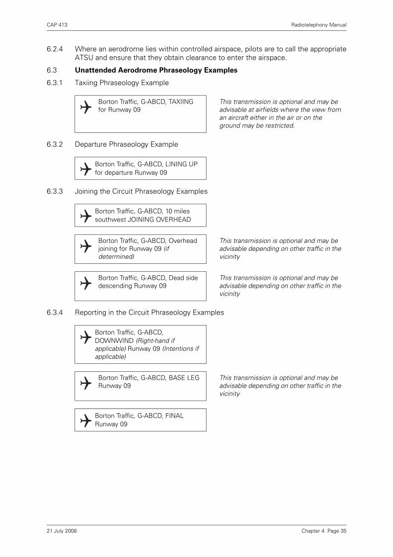
CAP 413 Radiotelephony Manual
6.2.4 Where an aerodrome lies within controlled airspace, pilots are to call the appropriateATSU and ensure that they obtain clearance to enter the airspace.
6.3 Unattended Aerodrome Phraseology Examples
6.3.1 Taxiing Phraseology Example
6.3.2 Departure Phraseology Example
6.3.3 Joining the Circuit Phraseology Examples
6.3.4 Reporting in the Circuit Phraseology Examples
Borton Traffic, G-ABCD, TAXIING for Runway 09
This transmission is optional and may be advisable at airfields where the view from an aircraft either in the air or on the ground may be restricted.
Borton Traffic, G-ABCD, LINING UP for departure Runway 09
Borton Traffic, G-ABCD, 10 miles southwest JOINING OVERHEAD
Borton Traffic, G-ABCD, Overhead joining for Runway 09 (if determined)
This transmission is optional and may be advisable depending on other traffic in the vicinity
Borton Traffic, G-ABCD, Dead side descending Runway 09
This transmission is optional and may be advisable depending on other traffic in the vicinity
Borton Traffic, G-ABCD, DOWNWIND (Right-hand if applicable) Runway 09 (Intentions if applicable)
Borton Traffic, G-ABCD, BASE LEG Runway 09
This transmission is optional and may be advisable depending on other traffic in the vicinity
Borton Traffic, G-ABCD, FINAL Runway 09
Chapter 4 Page 3521 July 2008

CAP 413 Radiotelephony Manual
Figure 2 Standard Overhead Join Procedure
First radio call should be made 5 - 10 miles from the aerodrome and joining checks completed.
Maintain 2000ft above aerodrome elevation or 1000ft above promulagated circuit level (based on QNH from the nearest available source), and observe windsock and traffi c. Keep aerodrome a suitable distance on the left of the aircraft. Report OVERHEAD. Include the appropriate runway if determined. If unable to ascertain the runway in use continue circling overhead.
When runway and circuit direction are ascertained begin letting down on the dead side. If required, report DEAD SIDE DESCENDING (Note: Once the circuit direction has been established, all turns must be in the circuit direction).
Position to cross within the upwind threshold at circuit height.
Watch for aircraft taking off, as they could pose a hazard.
Watch for existing circuit traffi c and adjust your path to sequence safely.
Call downwind.
Make optional call BASE LEG if required.
Report FINAL.
1
2
3
4
5
6
7
8
NOTE: This diagram is not to scale and is provided for illustrative purposes only
1400ft
1000ft
800ft
7
600ft
500ft
2000ft
8
1800ft
23
1200ft
41000ft
1000ft
56
LIVE
SID
EDE
AD S
IDE
SURFACE WIND
1
Chapter 4 Page 3621 July 2008
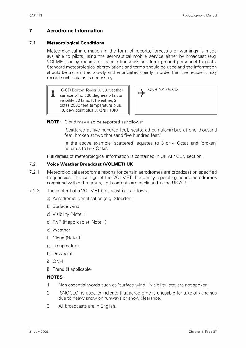
CAP 413 Radiotelephony Manual
7 Aerodrome Information
7.1 Meteorological Conditions
Meteorological information in the form of reports, forecasts or warnings is madeavailable to pilots using the aeronautical mobile service either by broadcast (e.g.VOLMET) or by means of specific transmissions from ground personnel to pilots.Standard meteorological abbreviations and terms should be used and the informationshould be transmitted slowly and enunciated clearly in order that the recipient mayrecord such data as is necessary.
NOTE: Cloud may also be reported as follows:
‘Scattered at five hundred feet, scattered cumulonimbus at one thousandfeet, broken at two thousand five hundred feet.’
In the above example ‘scattered’ equates to 3 or 4 Octas and ‘broken’equates to 5–7 Octas.
Full details of meteorological information is contained in UK AIP GEN section.
7.2 Voice Weather Broadcast (VOLMET) UK
7.2.1 Meteorological aerodrome reports for certain aerodromes are broadcast on specifiedfrequencies. The callsign of the VOLMET, frequency, operating hours, aerodromescontained within the group, and contents are published in the UK AIP.
7.2.2 The content of a VOLMET broadcast is as follows:
a) Aerodrome identification (e.g. Stourton)
b) Surface wind
c) Visibility (Note 1)
d) RVR (if applicable) (Note 1)
e) Weather
f) Cloud (Note 1)
g) Temperature
h) Dewpoint
i) QNH
j) Trend (if applicable)
NOTES:
1 Non essential words such as ‘surface wind’, ‘visibility’ etc. are not spoken.
2 ‘SNOCLO’ is used to indicate that aerodrome is unusable for take-off/landingsdue to heavy snow on runways or snow clearance.
3 All broadcasts are in English.
G-CD Borton Tower 0950 weather surface wind 360 degrees 5 knots visibility 30 kms. Nil weather, 2 oktas 2500 feet temperature plus 10, dew point plus 3, QNH 1010
QNH 1010 G-CD
Chapter 4 Page 3721 July 2008

CAP 413 Radiotelephony Manual
7.3 Runway Visual Range (RVR)/Visibility/Absolute Minimum
7.3.1 When transmitting the runway visual range the abbreviation RVR will be used withoutusing the phonetic word for each letter, e.g. RVR runway 27, 800 metres. The runwaydesignator may be omitted if there is no possibility of confusion.
7.3.2 Where instrumented runway visual range (IRVR) observations are available, morethan one reading may be transmitted.
7.3.3 In the UK, there is an approach ban which states that a pilot may not continue aninstrument approach beyond the outer marker or equivalent position, if the reportedRVR, or at aerodromes where RVR measurements are not taken or available, thevisibility, is below the minimum specified for that approach. Essentially, this meansthat a pilot may not descend below 1,000 feet above the aerodrome when theseconditions exist. This RVR/visibility is known as an ‘absolute minimum’.
7.3.4 Should a pilot indicate that he or she intends to commence an instrument approachwhen the reported RVR/visibility is less than the notified ‘absolute minimum’ value,the controller should inform the pilot using the following RTF phraseology:
7.4 Runway Surface Conditions
7.4.1 When conditions of standing water, with or without reports of braking action, arebrought to the attention of ATS, the available information will be passed to aircraftlikely to be affected.
7.4.2 When reports are based on inspections of the runway surface made by theaerodrome authority, the presence or otherwise of surface water on a runway will beassessed over the most significant portion of the runway (i.e., the area most likely tobe used by aircraft taking off and landing).
NOTE: This area may differ slightly from one runway to another but will approximateto the central two-thirds of the width of the runway extending longitudinallyfrom a point 100 m before the aiming point to 100 m beyond the aiming pointfor the reciprocal runway.
7.4.3 The presence or otherwise of surface water on a runway is reported in RTF and ATISbroadcasts using the following descriptions:
BIGJET 347 RVR runway 27 650 600 600
BIGJET 347
BIGJET 347 RVR runway 27 touchdown 650 stop end 550
BIGJET 347
BIGJET 347 you are advised that the current RVR/visibility is (number) metres which is below the absolute minimum for a (name) approach to runway (number). What are your intentions?
Chapter 4 Page 3821 July 2008
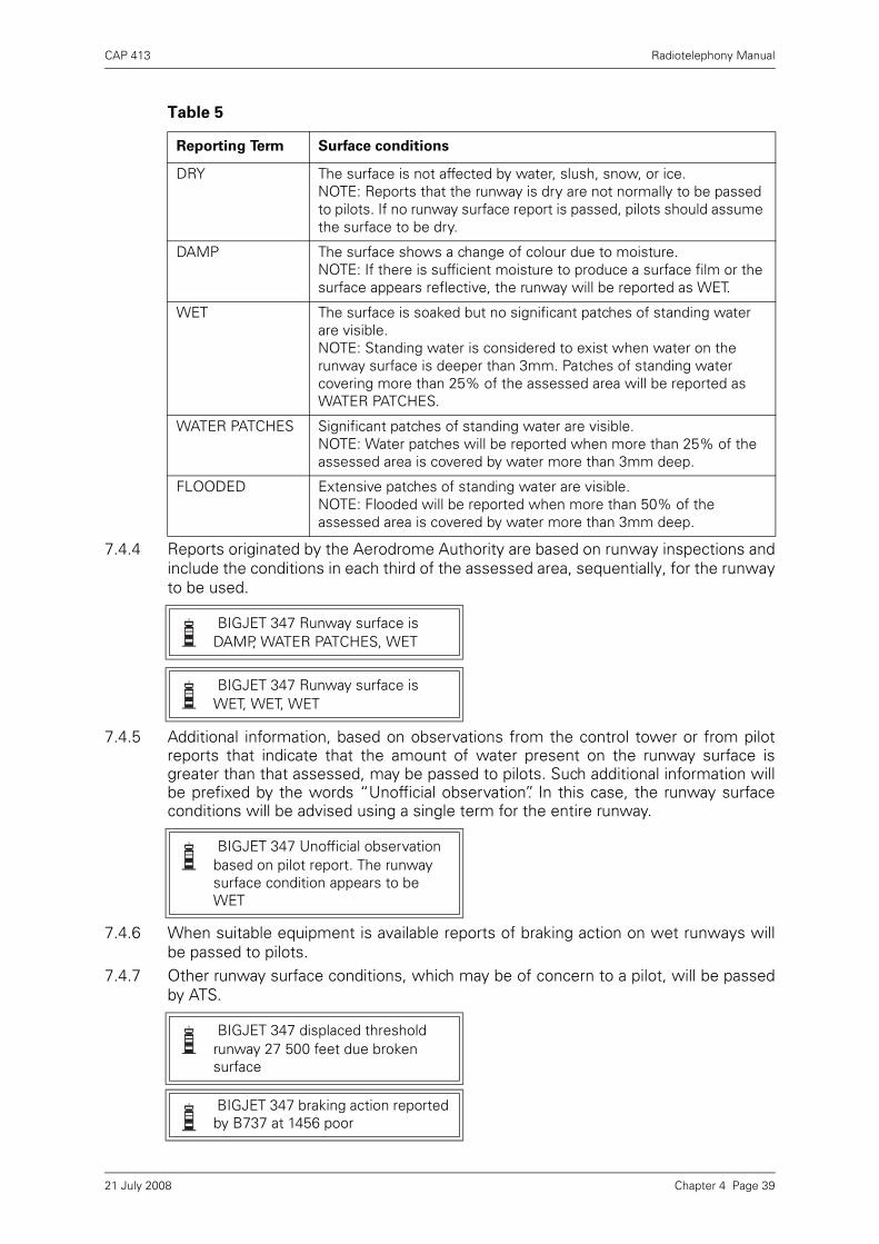
CAP 413 Radiotelephony Manual
7.4.4 Reports originated by the Aerodrome Authority are based on runway inspections andinclude the conditions in each third of the assessed area, sequentially, for the runwayto be used.
7.4.5 Additional information, based on observations from the control tower or from pilotreports that indicate that the amount of water present on the runway surface isgreater than that assessed, may be passed to pilots. Such additional information willbe prefixed by the words “Unofficial observation”. In this case, the runway surfaceconditions will be advised using a single term for the entire runway.
7.4.6 When suitable equipment is available reports of braking action on wet runways willbe passed to pilots.
7.4.7 Other runway surface conditions, which may be of concern to a pilot, will be passedby ATS.
Table 5
Reporting Term Surface conditions
DRY The surface is not affected by water, slush, snow, or ice.NOTE: Reports that the runway is dry are not normally to be passed to pilots. If no runway surface report is passed, pilots should assume the surface to be dry.
DAMP The surface shows a change of colour due to moisture.NOTE: If there is sufficient moisture to produce a surface film or the surface appears reflective, the runway will be reported as WET.
WET The surface is soaked but no significant patches of standing water are visible.NOTE: Standing water is considered to exist when water on the runway surface is deeper than 3mm. Patches of standing water covering more than 25% of the assessed area will be reported as WATER PATCHES.
WATER PATCHES Significant patches of standing water are visible.NOTE: Water patches will be reported when more than 25% of the assessed area is covered by water more than 3mm deep.
FLOODED Extensive patches of standing water are visible.NOTE: Flooded will be reported when more than 50% of the assessed area is covered by water more than 3mm deep.
BIGJET 347 Runway surface is DAMP, WATER PATCHES, WET
BIGJET 347 Runway surface is WET, WET, WET
BIGJET 347 Unofficial observation based on pilot report. The runway surface condition appears to be WET
BIGJET 347 displaced threshold runway 27 500 feet due broken surface
BIGJET 347 braking action reported by B737 at 1456 poor
Chapter 4 Page 3921 July 2008

CAP 413 Radiotelephony Manual
7.5 Automatic Terminal Information Service (ATIS) UK
7.5.1 To alleviate RTF loading at some busy airports, Automatic Terminal InformationService (ATIS) messages are broadcast to pass routine arrival/departure informationon a discrete RTF frequency or on an appropriate VOR. Pilots inbound to theseairports are normally required, on first contact with the aerodrome ATSU, toacknowledge receipt of current information by quoting the code letter of thebroadcast. Pilots of outbound aircraft are not normally required to acknowledgereceipt of departure ATIS except when requested on the actual ATIS broadcast. If,however, pilots report receipt of a departure ATIS broadcast the QNH should beincluded, thereby allowing ATC to check that the quoted QNH is up-to-the-minute.
7.5.2 Aerodromes possessing ATIS, the hours of ATIS operation and the frequencyemployed are published in the UK AIP.
7.5.3 ATIS broadcasts (which should be no more than thirty seconds duration) will includethe following:
a) Message identification i.e. ‘This is Stourton Information Alpha’. Each message isconsecutively coded using the phonetic alphabet.
b) Time of origin of weather report.
c) Weather report (see paragraph 2.2(a)–(c)).
d) Runway(s) in use.
e) Short term AIS information such as unserviceability of NAV AIDS, runway surfacesetc.
f) Any other routine information useful to pilots operating at the aerodrome.
NOTES:
1 RVR/RVRs are not included, however, IRVRs may be available where approved.
2 Rapidly changing meteorological situations sometimes make it impractical toinclude weather reports in the broadcast. In these circumstances, ATISmessages will indicate that weather information will be passed on RTF.
3 Any significant change to the content of a current ATIS message will be passedto pilots by RTF until such time as a new message is broadcast.
4 The highest cloud base that will be reported is 10000 feet.
7.5.4 Example of ATIS broadcast:
‘This is Stourton Approach Information Alpha. 0850 hours weather. 240° 12 kts.10 km. Intermittent slight rain. Scattered at 1000 ft, overcast at 1800 ft. Temperature+12. Dew point +7. QNH 1011 mbs. Landing runway 28. Report information Alphareceived on first contact with Stourton.’
NOTE: A Trend may be included in an ATIS broadcast.
Chapter 4 Page 4021 July 2008

CAP 413 Radiotelephony Manual
Chapter 5 Radar Phraseology
1 General
1.1 Introduction
1.1.1 This Chapter contains general radar phraseology which is commonly used incommunications between aircraft and all types of radar unit. Phraseology which ismore applicable to approach radar control or area control is to be found in Chapters 6and 7 as appropriate.
1.1.2 The phrase ‘under radar control’ shall only be used when a radar control service isbeing provided. Normally however, the callsign suffix used by the radar unit issufficient to indicate its function.
1.1.3 In a radar environment heading information given by the pilot and heading instructionsgiven by controllers are normally in degrees magnetic.
1.2 Radar Identification of Aircraft
1.2.1 An aircraft must be identified before it can be provided with a radar service. However,the act of identifying aircraft is not a service in itself and pilots should not assume thatthey are receiving a radar service, particularly when they are flying outside controlledairspace.
or,
G-CD report heading G-CD heading 350
G-CD for identification turn left heading 320 degrees
Left heading 320 degrees G-CD
G-CD identified 18 miles north-west of Borton, Radar Advisory
Radar Advisory G-CD
G-CD not identified. Resume own navigation
Wilco G-CD
Chapter 5 Page 121 July 2008

CAP 413 Radiotelephony Manual
1.2.2 When a controller has identified an aircraft he will inform the pilot, according to thecircumstances, of the following:
a) that the aircraft is identified, and
b) of the position of the aircraft.
The occasions when the above information will be passed can be summarised asfollows:
1.2.3 The pilot will be warned if identification is lost, or about to be lost, and appropriateinstructions given.
1.3 Secondary Surveillance Radar Phraseology
1.3.1 The following phrases are instructions which may be given by controllers to pilotsregarding the operation of SSR transponders. The phrases used by controllers aregiven together with their meanings; assignment of a code does not constitute theprovision of a radar service.
Table 1
Method of
Identification
Aircraft flying inside
controlled airspace
Aircraft flying outside
controlled airspace
Inform
Identified
Pass
Position
Inform
Identified
Pass
Position
SSR No No Yes Yes
Turn Yes Yes Yes Yes
Departing aircraft No No Yes No
Position Report No No Yes No
G-CD radar service terminated due radar failure. Resume own navigation. Flight Information available from Wrayton on 125.750
Changing to Wrayton 125.750 G-CD
G-CD will shortly be leaving radar cover, radar service terminated. Flight Information available from Wrayton on 125.750
G-CD changing to Wrayton 125.750
G-CD
Chapter 5 Page 221 July 2008

CAP 413 Radiotelephony Manual
*Used to verify the accuracy of the Mode C derived level information displayed to thecontroller.
1.3.2 The pilot must respond to SSR instructions, reading back specific settings.
Table 2
Phrase Meaning
Squawk (code) Set the code as instructed
Confirm squawk Confirm the code set on the transponder
Reset squawk (code) Reselect assigned code
Squawk Ident Operate the special position identification feature
Squawk Mayday Select Emergency
Squawk Standby Select the standby feature
Squawk Charlie Select altitude reporting feature
Check altimeter setting and confirm (level) Check pressure setting and confirm your level
Stop squawk Charlie Deselect altitude reporting
Stop squawk Charlie, wrong indication Stop altitude report, incorrect level readout
* Confirm (level) Check and confirm your level
BIGJET 347 squawk 6411 6411 BIGJET 347
BIGJET 347 squawk ident Squawk ident, BIGJET 347
BIGJET 347 squawk 6411 and ident 6411 and ident, BIGJET 347
BIGJET 347 confirm squawk 6411 BIGJET 347
BIGJET 347 reset squawk 6411 Resetting 6411 BIGJET 347
BIGJET 347 check altimeter setting 1013 set BIGJET 347
BIGJET 347 confirm transponder operating
BIGJET 347 negative, transponder unserviceable
Chapter 5 Page 321 July 2008

CAP 413 Radiotelephony Manual
1.4 Radar Service
Where it is not self-evident pilots will normally be informed by the controller whenthey are under radar control, advisory or information service.
1.5 Radar Vectoring
1.5.1 Aircraft may be given specific vectors to fly in order to establish separation. Pilots maybe informed of the reasons for radar vectoring.
1.5.2 It may be necessary for a controller to know the heading of an aircraft as separationcan often be established by instructing an aircraft to continue on its existing heading.
1.5.3 A controller may not know the aircraft’s heading but does require the aircraft to fly aparticular heading.
BIGJET 347 under Radar Control Radar Control BIGJET 347
G-CD Radar Advisory Radar Advisory G-CD
G-CD Radar Information Radar Information G-CD
BIGJET 347 radar service terminated
BIGJET 347
BIGJET 347 delaying action. Turn left heading 050 degrees
Left heading 050 degrees BIGJET 347
BIGJET 347 continue present heading
Continue heading BIGJET 347
BIGJET 347 report heading BIGJET 347 heading 050 degrees
BIGJET 347 continue present heading and report that heading
Continue heading 050 degrees BIGJET 347
BIGJET 347 continue heading 050 degrees
Continue heading 050 degrees BIGJET 347
G-CD fly heading 275 Roger, turning left heading 275, G-CD
Chapter 5 Page 421 July 2008
CAP 413 Radiotelephony Manual
or,
1.5.4 When vectoring is complete, pilots will be instructed to resume their own navigation,given position information and appropriate instructions as necessary.
1.5.5 Occasionally an aircraft may be instructed to make a complete turn (known as an orbitor a 360 degree turn), for delaying purposes or to achieve a required spacing behindpreceding traffic.
NOTE: 360 turn spoken as “TREE SIXTY TURN”
1.6 Traffic Information and Avoiding Action Phraseology
1.6.1 Whenever practicable, information regarding traffic on a possible conflicting pathshould be given in the following form:
a) relative bearing of the conflicting traffic in terms of the 12 hour clock; or, if theaircraft under service is established in a turn, the relative position of the conflictingtraffic in relation to cardinal points i.e. northwest, south etc.;
b) distance from the conflicting traffic;
c) direction of flight of the conflicting traffic; and
d) relative speed of the conflicting traffic or the type of aircraft and level if this isknown.
1.6.2 Relative movement and level should be described by using one of the following termsas applicable:
a) ‘closing, converging, parallel, same direction, opposite direction diverging,overtaking, crossing left to right, crossing right to left’;
b) ‘level (if known), unverified or 1000 feet above/below’; or,
c) (when giving traffic information to an aircraft which is climbing or descending)‘… 1000 feet above/below your cleared level.’
Roger, turning right 20 degrees heading 275, G-CD
BIGJET 347 resume own navigation for Wicken, magnetic track 075 distance 27 miles
Wilco BIGJET 347
G-CD resume own navigation for Walden position is 15 miles southeast of Westbury
Wilco G-CD
G-CD delaying action, orbit left for sequencing
Orbit left G-CD
BIGJET 347 delaying action. Make a 360 turn left
360 turn left BIGJET 347
Chapter 5 Page 521 July 2008

CAP 413 Radiotelephony Manual
1.6.3 The controller will inform the pilot when the conflict no longer exists.
1.6.4 Avoiding action to be taken by the pilot is given when the controller considers that animminent risk of collision will exist if action is not taken immediately
or,
1.7 ACAS/TCAS Phraseology
1.7.1 ACAS/TCAS equipment reacts to transponders of other aircraft in the vicinity todetermine whether or not there is a potential confliction. The warning (TrafficAdvisory), based on the time to an assumed collision enables the pilot to identify theconflicting traffic, and if necessary, take avoiding action (Resolution Advisory). In theUK, this equipment is mainly referred to as ‘TCAS’, however, the use of ‘ACAS’ is anacceptable alternative in phraseology terms.
1.7.2 Pilots should report TCAS manoeuvres.
(Controllers may issue a revised clearance at this point.)
1.7.3 The pilot should report a TCAS manoeuvre even if it was not possible to notify theController that an Resolution Advisory had occurred.
or,
G-CD unknown traffic 10 o’clock 6 miles crossing left to right height unknown fast moving. If not sighted turn left heading 270 degrees
Left heading 270 degrees G-CD
G-CD clear of traffic resume own navigation direct Walden magnetic track 350 distance 13 miles
Wilco G-CD
G-CD avoiding action, turn left immediately heading 270 degrees traffic at 10 o’clock 5 miles crossing left to right indicating 3000 feet unverified
Left heading 270 degrees G-CD
G-CD avoiding action descend immediately FL 280. Traffic 12 o’clock, 10 miles opposite direction, same level
Descend immediately FL 280, G-CD
BIGJET 347 TCAS RA BIGJET 347 Roger
BIGJET 347 clear of conflict, returning to (assigned clearance)
BIGJET 347 Roger
BIGJET 347 clear of conflict, returning to (assigned clearance)
BIGJET 347 Roger
Chapter 5 Page 621 July 2008
CAP 413 Radiotelephony Manual
(Controllers may issue a revised clearance at this point.)
1.7.4 Pilots should report that they are unable to comply with a clearance as a result of aTCAS alert.
In these circumstances the pilot should report when clear of the TCAS conflict.
1.8 Communications and Loss of Communications
When a controller suspects that an aircraft is able to receive but not transmitmessages, the radar may be used to confirm that the pilot has received instructions.When further instructions are given they should be passed slowly, clearly and berepeated.
or,
NOTES:
1 An aircraft experiencing a radio communications failure is expected to selectthe appropriate SSR code.
2 See also Chapter 8.
1.9 Danger Area Crossing Service/Danger Area Activity Information Service
1.9.1 In-flight information on the status of Danger Areas (DAs) is available from thenominated service units:
a) Listed in the UK AIP.
b) Detailed on the legend of the appropriate UK 1:500 000 Aeronautical Chart.
1.9.2 When available the DA service will either be a Danger Area Crossing Service (DACS)or a Danger Area Activity Information Service (DAAIS). If there is no reply from theappropriate nominated service unit which is to be called for these services, pilots areadvised to assume that the relevant danger area is active.
BIGJET 347 clear of conflict, (assigned clearance) resumed
BIGJET 347 Roger
BIGJET 347 unable TCAS RA BIGJET 347 Roger
G-CD reply not received if you read Wrayton turn left heading 040 degrees I say again turn left heading 040 degrees
G-CD turn observed I will continue to pass instructions
BIGJET 347 reply not received if you read Wrayton squawk ident I say again squawk ident
BIGJET 347 squawk observed I will continue to pass instructions
Chapter 5 Page 721 July 2008

CAP 413 Radiotelephony Manual
1.9.3 Danger Area Crossing Service
The appropriate nominated service unit will, whenever the DA activity permits,provide a clearance for an aircraft to cross the danger area under a suitable type ofservice. The clearance is only in relation to Danger Area activity and does not, in trafficmanagement terms, constitute separation from aircraft which might be operating inthe area.
or,
Westbury Approach, G-ABCD request Danger Area Crossing Service of Loudwater Range
G-ABCD Westbury Approach (Type of Service). Loudwater active. Report 10 miles from Loudwater
Wilco G-ABCD
Westbury Approach G-ABCD 10 miles from Loudwater
G-CD Loudwater remains active. Suggest you re-route
Re-routing to the east of Loudwater and changing to Wrayton
Information 125.750 G-ABCD
G-ABCD
G-ABCD Westbury Approach. Loudwater not active, range crossing
approved report vacating the range
Range crossing approved. Wilco G-ABCD
G-ABCD vacating Loudwater Range
G-CD Westbury Approach roger, Flight Information available from Wrayton on
125.750
Changing to Wrayton on 125.750 G-CD
Chapter 5 Page 821 July 2008

CAP 413 Radiotelephony Manual
1.9.4 Danger Area Activity Information Service
The nominated service unit will pass to the pilot, on request, an update on the knownactivity status of the danger area. Such an update will assist the pilot to decidewhether it would be prudent, on flight safety grounds, to penetrate the Danger Area.A DAAIS does NOT constitute a clearance to cross a Danger Area.
1.9.5 Full details of DACS/DAAIS can be found in the UK AIP and AICs.
Westbury Approach G-ABCD request DAAIS for Loudwater Range
G-ABCD Westbury Approach Loudwater Active/Not Active
Loudwater Active/Not Active G-ABCD
Chapter 5 Page 921 July 2008

INTENTIONALLY LEFT BLANK
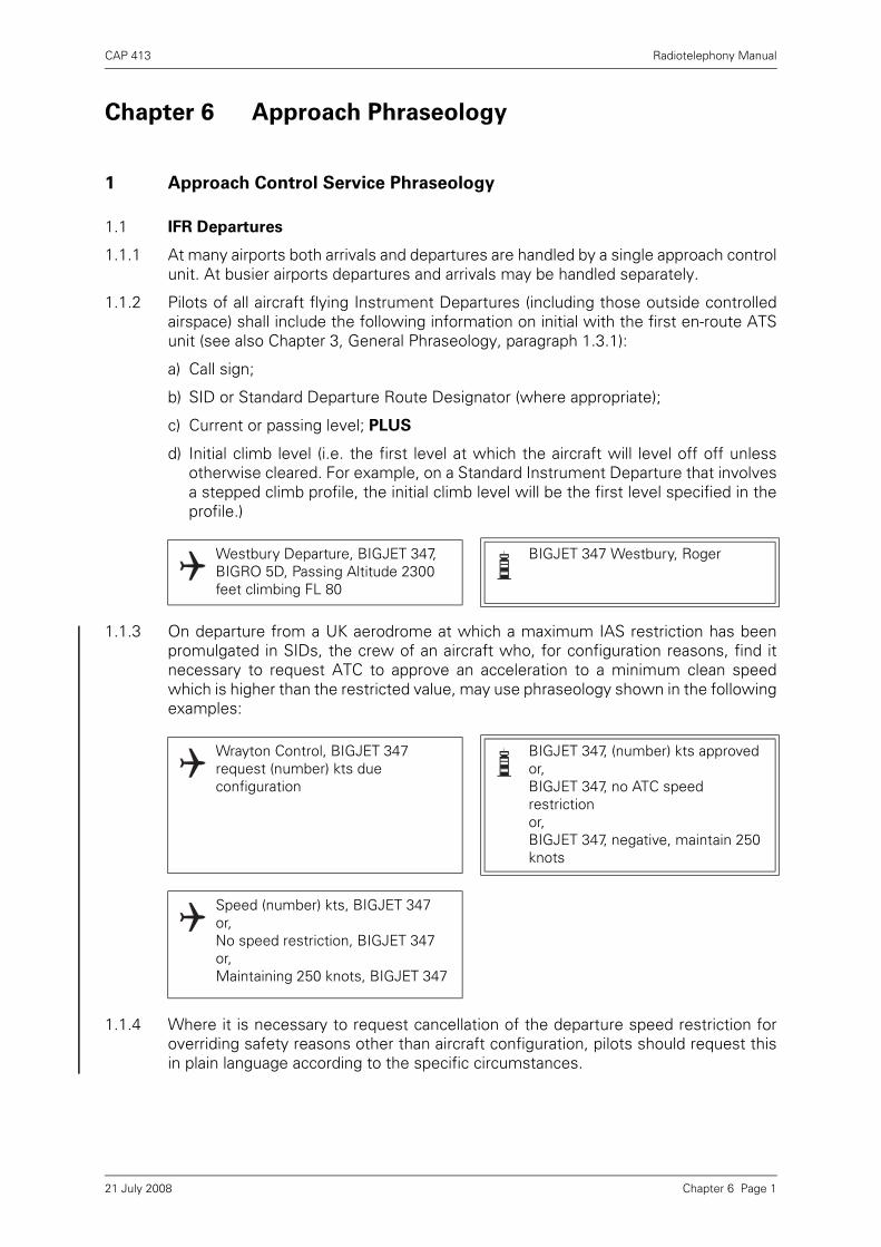
CAP 413 Radiotelephony Manual
Chapter 6 Approach Phraseology
1 Approach Control Service Phraseology
1.1 IFR Departures
1.1.1 At many airports both arrivals and departures are handled by a single approach controlunit. At busier airports departures and arrivals may be handled separately.
1.1.2 Pilots of all aircraft flying Instrument Departures (including those outside controlledairspace) shall include the following information on initial with the first en-route ATSunit (see also Chapter 3, General Phraseology, paragraph 1.3.1):
a) Call sign;
b) SID or Standard Departure Route Designator (where appropriate);
c) Current or passing level; PLUS
d) Initial climb level (i.e. the first level at which the aircraft will level off off unlessotherwise cleared. For example, on a Standard Instrument Departure that involvesa stepped climb profile, the initial climb level will be the first level specified in theprofile.)
1.1.3 On departure from a UK aerodrome at which a maximum IAS restriction has beenpromulgated in SIDs, the crew of an aircraft who, for configuration reasons, find itnecessary to request ATC to approve an acceleration to a minimum clean speedwhich is higher than the restricted value, may use phraseology shown in the followingexamples:
1.1.4 Where it is necessary to request cancellation of the departure speed restriction foroverriding safety reasons other than aircraft configuration, pilots should request thisin plain language according to the specific circumstances.
Westbury Departure, BIGJET 347, BIGRO 5D, Passing Altitude 2300 feet climbing FL 80
BIGJET 347 Westbury, Roger
Wrayton Control, BIGJET 347 request (number) kts due configuration
BIGJET 347, (number) kts approvedor,BIGJET 347, no ATC speed restrictionor,BIGJET 347, negative, maintain 250 knots
Speed (number) kts, BIGJET 347or,No speed restriction, BIGJET 347or,Maintaining 250 knots, BIGJET 347
Chapter 6 Page 121 July 2008

CAP 413 Radiotelephony Manual
1.1.5 In addition to the ATC route clearance, departing IFR flights may be given additionalinstructions to provide separation in the immediate vicinity.
1.2 VFR Departures
1.2.1 Departing VFR flights, when handled by approach control, may be passed informationon relevant known traffic in order to assist the pilot in maintaining his own separation.Pilots should report leaving the area of jurisdiction of the approach control units.
1.2.2 Special VFR flights will be given specific instructions in the clearance to leave thecontrol zone.
BIGJET 347 Stourton Approach continue heading 040 degrees until passing FL 70 then route direct Wicken
Heading 040 degrees until passing FL 70 then direct Wicken BIGJET 347
BIGJET 347 report passing FL 70
BIGJET 347 passing FL 70 routeing direct Wicken
BIGJET 347 contact Wrayton Control 129.1
Wrayton Control 129.1 BIGJET 347
Borton Approach G-CD passing the zone boundary
G-CD Flight Information available from Wrayton 125.750
Wrayton Information 125.750 G-CD
G-CD cleared to the zone boundary route via Whiskey Special VFR not above altitude 1500 feet
Cleared to the zone boundary, route via Whiskey Special VFR not above altitude 1500 feet G-CD
G-CD correct
Chapter 6 Page 221 July 2008

CAP 413 Radiotelephony Manual
1.3 IFR Arrivals
1.3.1 Aircraft flying within controlled airspace will normally receive descent clearance to theclearance limit from the ACC prior to transfer to an approach control unit. On transferto approach control further descent instructions may be given.
1.3.2 Arriving IFR flights operating outside controlled airspace are not permitted to entercontrolled airspace until cleared to do so. In the examples below the initial approachfix is Kennington NDB (or VOR), callsign KTN.
Kennington Approach BIGJET 347 descending FL 90 Information Charlie
BIGJET 347 Kennington Approach cleared direct to North Cross descend FL 50
Direct to North Cross descend FL 50 BIGJET 347
Kennington Approach BIGJET 347 BIGJET 347 Kennington Approach pass your message
BIGJET 347 from Stourton 25 miles southeast Kennington IFR, FL 125 estimating zone boundary 20 KTN 24 information Charlie
BIGJET 347 cleared from 10 miles southeast of Kennington to KTN at FL 60. Enter controlled airspace at FL 85 or below
Cleared from 10 miles southeast of Kennington to KTN at FL 60. Enter controlled airspace southeast of Kennington at FL 85 or below BIGJET 347
BIGJET 347 expect ILS approach runway 28 QNH 1011
ILS runway 28 QNH 1011 Request straight in approach BIGJET 347
BIGJET 347 cleared straight in ILS approach runway 28, descend to altitude 3000 feet QNH 1011, report established on the localiser
Cleared straight in ILS approach runway 28 descend to altitude 3000 feet QNH 1011, Wilco BIGJET 347
Chapter 6 Page 321 July 2008

CAP 413 Radiotelephony Manual
BIGJET 347 established on the localiser
BIGJET 347 runway in sight
BIGJET 347 number 1 contact Tower 118.7
Number 1 Tower 118.7 BIGJET 347
Kennington Tower BIGJET 347 BIGJET 347 Kennington Tower report outer marker
BIGJET 347
BIGJET 347 outer marker BIGJET 347 runway 28 cleared to land surface wind 280 8
Runway 28 cleared to land BIGJET 347
Kennington Approach G-DCAB G-DCAB Kennington Approach pass your message
G-DCAB PA 31 inbound from Stourton IFR FL 80 estimate KTN 47 information Delta
G-AB remain outside controlled airspace. Time is 41. Expect joining clearance at 44
Remain outside controlled airspace, G-AB
G-AB cleared from 10 miles southeast of Kennington to KTN at FL 80
Cleared from 10 miles southeast of Kennington to KTN at FL 80 G-AB
Chapter 6 Page 421 July 2008

CAP 413 Radiotelephony Manual
NOTE: Pilots may be requested to change to tower frequency at any point on finalapproach.
G-AB expect ILS approach runway 28
G-AB
G-AB descend to altitude 3000 feet QNH 1011
Descend to altitude 3000 feet QNH 1011 G-AB
G-AB cleared ILS approach runway 28 report KTN outbound
Cleared ILS runway 28, Wilco G-AB
G-AB KTN outbound
G-AB report procedure turn complete
Wilco, G-AB
G-AB procedure turn complete localiser established
G-AB report at outer marker
Wilco G-AB
G-AB outer marker
G-AB contact Tower 118.9
Tower 118.9 G-AB
Chapter 6 Page 521 July 2008

CAP 413 Radiotelephony Manual
1.3.3 On occasions IFR aircraft do not complete the instrument approach procedure butrequest permission to make a visual approach.
1.3.4 Normally a holding procedure is published. However, the pilot may require a detaileddescription of a specific holding procedure.
It should be noted that the above information is passed in the following order and isfor holds other than VOR/DME:
a) Fix
b) Level
c) Inbound track
d) Right or left turns
e) Time of leg
1.3.5 Holding information for VOR/DME substitutes DISTANCE for TIME in e) above:
1.4 VFR Arrivals
1.4.1 Depending on the procedures in use, the pilot of an arriving VFR flight may berequired to establish contact with the approach control unit and request instructionsbefore entering its area of jurisdiction e.g. before entering a control zone. Where thereis an ATIS broadcast the pilot should acknowledge that he has received it; where noATIS broadcast is provided the approach controller will pass the aerodrome data.
G-AB over KTN 3000 feet field in sight, request visual approach
G-AB cleared visual approach runway 28
Cleared visual approach runway 28 G-AB
BIGJET 347 hold at North Cross FL 60 expect onward clearance at time 40
Hold at North Cross FL 60, request holding procedure BIGJET 347
BIGJET 347 hold at North Cross FL 60 inbound track 260 degrees turns left outbound time 1 minute
BIGJET 347 request holding procedure
BIGJET 347 hold on the Marlow VOR/DME at 20 DME FL 100 inbound track 260 degrees turns left, limiting outbound distance 24 DME
Kennington Approach G-DCDNRequest join
G-DCDN Kennington Approach pass your message
Chapter 6 Page 621 July 2008

CAP 413 Radiotelephony Manual
NOTE: The phraseology for joining the aerodrome traffic circuit is detailed inChapter 4, paragraph 1.8.
1.5 Special VFR Flights
1.5.1 Special VFR clearances are only issued for flights within Control Zones and arenormally at the request of the pilot. The pilot:
a) must comply with ATC instructions;
b) is responsible for ensuring that his flight conditions enable him to remain clear ofcloud, determine his flight path with reference to the surface and to keep clear ofobstructions;
c) is responsible for ensuring that he flies within the limitations of his licence;
d) is responsible for complying with the relevant low flying restrictions of Rules 5 and6 of the Rules of the Air Regulations.
NOTE: Whilst the 1000 ft rule may not apply to a pilot in receipt of a Special VFRclearance, the ‘alight clear’ rule always applies.
The responsibility to determine whether to accept a Special VFR clearance and stillcomply with this rule rests with the pilot;
e) is responsible for avoiding aerodrome traffic zones unless prior permission forpenetration has been obtained from the relevant ATSU.
G-DCDN C172 inbound from Stourton VFR 2500 feet Wessex 1011 estimating zone boundary 52 Kennington 02 information golf
G-DN cleared from the zone boundary to Kennington VFR, at 2500 feet Kennington QNH 1012. Traffic is a southbound Cherokee 2000 feet VFR estimating zone boundary 53
Cleared from the zone boundary to Kennington VFR at 2500 feet QNH 1012, traffic in sight G-DN
G-DN report aerodrome in sight
Wilco G-DN
G-DN aerodrome in sight
G-DN contact Tower 118.5
Tower 118.5 G-DN
Chapter 6 Page 721 July 2008

CAP 413 Radiotelephony Manual
1.5.2 A full flight plan is not required for Special VFR flight but the pilot must give briefdetails of the callsign, aircraft type and pilot’s intentions, including ETA at entry point.A full flight plan is required if the pilot wishes his destination to be notified.
1.5.3 Aircraft are not normally given a specific height to fly but vertical separation fromaircraft flying above can be achieved by requiring the Special VFR flight to fly notabove a specified level (paragraph d) above must be borne in mind by pilots).
1.5.4 No separation will be provided between Special VFR flights which are flying in notifiedareas or routes where an individual clearance is not required, or between flights usingsuch areas or routes and other flights on Special VFR clearances. Full details of theprocedures for Special VFR flights appear in the UK AIP, ENR, Section 1.
1.6 Vectoring to Final Approach
1.6.1 Radar vectors are given to arriving flights to position them onto a pilot interpretedapproach aid, to a point from which a radar-assisted approach can be made or to apoint from which a visual approach is made.
1.6.2 MLS equipment will provide an “ILS look-a-like” straight in approach and the terms“Localiser” and “Glidepath” are retained. Due to the possibility of confusion betweenthe words “ILS” and “MLS”, an MLS approach is referred to as a “MicrowaveApproach” in RTF communication.
1.6.3 In the following example an identified aircraft inbound to Kennington is given radarvectors to the ILS. Where applicable “Microwave” is shown (in brackets) to indicateappropriate MLS phraseology (see Figure 3.)
Figure 1 Radar vectors to an ILS approach
Chapter 6 Page 821 July 2008
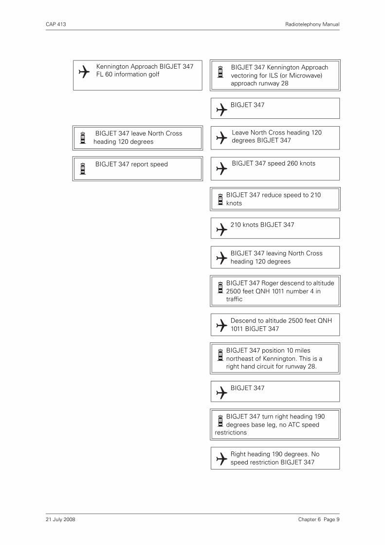
CAP 413 Radiotelephony Manual
Kennington Approach BIGJET 347 FL 60 information golf
BIGJET 347 Kennington Approach vectoring for ILS (or Microwave) approach runway 28
BIGJET 347
BIGJET 347 leave North Cross heading 120 degrees
Leave North Cross heading 120 degrees BIGJET 347
BIGJET 347 report speed BIGJET 347 speed 260 knots
BIGJET 347 reduce speed to 210 knots
210 knots BIGJET 347
BIGJET 347 leaving North Cross heading 120 degrees
BIGJET 347 Roger descend to altitude 2500 feet QNH 1011 number 4 in traffic
Descend to altitude 2500 feet QNH 1011 BIGJET 347
BIGJET 347 position 10 miles northeast of Kennington. This is a right hand circuit for runway 28.
BIGJET 347
BIGJET 347 turn right heading 190 degrees base leg, no ATC speed
restrictions
Right heading 190 degrees. No speed restriction BIGJET 347
Chapter 6 Page 921 July 2008
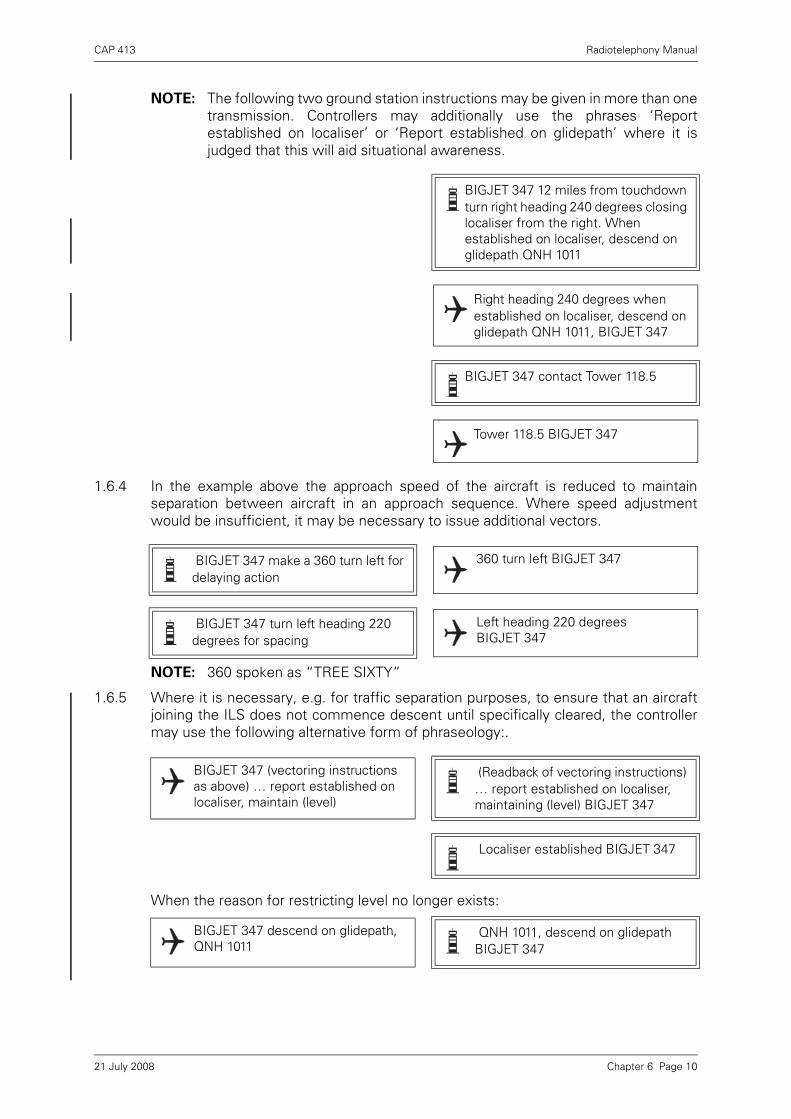
CAP 413 Radiotelephony Manual
NOTE: The following two ground station instructions may be given in more than onetransmission. Controllers may additionally use the phrases ‘Reportestablished on localiser’ or ‘Report established on glidepath’ where it isjudged that this will aid situational awareness.
1.6.4 In the example above the approach speed of the aircraft is reduced to maintainseparation between aircraft in an approach sequence. Where speed adjustmentwould be insufficient, it may be necessary to issue additional vectors.
NOTE: 360 spoken as “TREE SIXTY”
1.6.5 Where it is necessary, e.g. for traffic separation purposes, to ensure that an aircraftjoining the ILS does not commence descent until specifically cleared, the controllermay use the following alternative form of phraseology:.
When the reason for restricting level no longer exists:
BIGJET 347 12 miles from touchdown turn right heading 240 degrees closing localiser from the right. When established on localiser, descend on glidepath QNH 1011
Right heading 240 degrees when established on localiser, descend on glidepath QNH 1011, BIGJET 347
BIGJET 347 contact Tower 118.5
Tower 118.5 BIGJET 347
BIGJET 347 make a 360 turn left for delaying action
360 turn left BIGJET 347
BIGJET 347 turn left heading 220 degrees for spacing
Left heading 220 degrees BIGJET 347
BIGJET 347 (vectoring instructions as above) … report established on localiser, maintain (level)
(Readback of vectoring instructions) … report established on localiser, maintaining (level) BIGJET 347
Localiser established BIGJET 347
BIGJET 347 descend on glidepath, QNH 1011
QNH 1011, descend on glidepath BIGJET 347
Chapter 6 Page 1021 July 2008

CAP 413 Radiotelephony Manual
1.7 Direction Finding (DF)
1.7.1 The aeronautical stations that offer a VHF Direction Finding (VDF) service are listed inthe UK AIP AD. Some VDF stations stipulate that the service is not available for en-route navigation purposes (except in emergency). VDF bearing information will onlybe given when conditions are satisfactory and radio bearings fall within calibratedlimits of the station. If the provision of a radio bearing is not possible the pilot will betold of the reason.
A pilot may request a bearing or heading using the appropriate phrase or Q code tospecify the service required. Each aircraft transmission shall be ended by the aircraftcall sign. A VDF station will provide the following as requested:
a) QDR – Magnetic bearing of the aircraft from the station (i.e. ..... Approach G-ABCDrequest QDR G-ABCD).
b) QDM – Magnetic heading to be steered by the aircraft (assuming no wind) to reachthe VDF station (i.e. ..... Approach G-ABCD request QDM G-ABCD).
c) QTE – True bearing of the aircraft from the station (i.e. ...... True bearing, Truebearing ..... Approach G-ABCD request True bearing (or QTE) G-ABCD).
The direction-finding station will reply in the following manner:
a) The appropriate phrase or Q code.
b) The bearing or heading in degrees in relation to the direction finding station.
c) The class of bearing.
d) The time of observation, if necessary.
1.7.2 The accuracy of the observation is classified as follows:
Class A – Accurate within plus or minus 2 degrees
Class B – Accurate within plus or minus 5 degrees
Class C – Accurate within plus or minus 10 degrees
Class D – Accuracy less than Class C
NOTE: Normally no better than Class B bearing will be available.
1.8 VDF Procedure
1.8.1 This is a procedure whereby a pilot requests a series of QDMs to home to a VDFstation on or near an aerodrome and to carry out a prescribed VDF instrument
Kennington Approach G-ABCD request QDM G-ABCD
G-ABCD Kennington Approach QDM 090 degrees class Bravo
QDM 090 degrees class Bravo G-ABCD
True bearing, true bearing, Kennington Approach G-ABCD request true bearing G-ABCD
G-ABCD Kennington Approach true bearing 276 degrees true, I say again, 276 degrees true class bravo
True bearing 276 degrees class Bravo G-ABCD
Chapter 6 Page 1121 July 2008
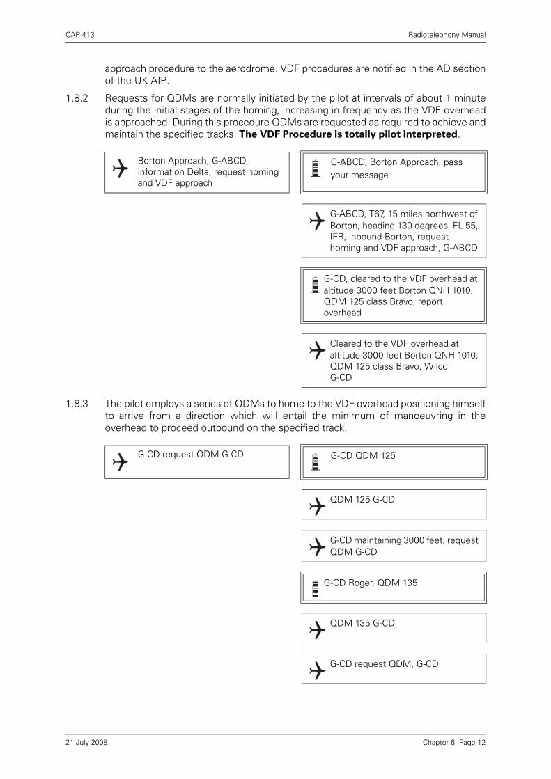
CAP 413 Radiotelephony Manual
approach procedure to the aerodrome. VDF procedures are notified in the AD sectionof the UK AIP.
1.8.2 Requests for QDMs are normally initiated by the pilot at intervals of about 1 minuteduring the initial stages of the homing, increasing in frequency as the VDF overheadis approached. During this procedure QDMs are requested as required to achieve andmaintain the specified tracks. The VDF Procedure is totally pilot interpreted.
1.8.3 The pilot employs a series of QDMs to home to the VDF overhead positioning himselfto arrive from a direction which will entail the minimum of manoeuvring in theoverhead to proceed outbound on the specified track.
Borton Approach, G-ABCD, information Delta, request homing and VDF approach
G-ABCD, Borton Approach, pass your message
G-ABCD, T67, 15 miles northwest of Borton, heading 130 degrees, FL 55, IFR, inbound Borton, request homing and VDF approach, G-ABCD
G-CD, cleared to the VDF overhead at altitude 3000 feet Borton QNH 1010, QDM 125 class Bravo, report overhead
Cleared to the VDF overhead at altitude 3000 feet Borton QNH 1010, QDM 125 class Bravo, Wilco G-CD
G-CD request QDM G-CD G-CD QDM 125
QDM 125 G-CD
G-CD maintaining 3000 feet, request QDM G-CD
G-CD Roger, QDM 135
QDM 135 G-CD
G-CD request QDM, G-CD
Chapter 6 Page 1221 July 2008

CAP 413 Radiotelephony Manual
1.8.4 The pilot starts timing the outbound leg and, employing a series of QDMs to establishand maintain the prescribed track, descends as notified for the procedure. The timedoutbound leg ends with a turn (normally level) onto the final approach QDM.
G-CD QDM 145, cleared VDF approach runway 34
QDM 145, cleared VDF approach runway 34 G-CD
G-CD request QDM G-CD
G-CD QDM 155
QDM 155 G-CD
G-CD request QDM G-CD
G-CD no bearing
G-CD request QDM G-CD
G-CD no bearing
G-CD overhead turning outbound
G-CD report descending in the procedure QNH 1010
Wilco, QNH 1010 G-CD
G-CD request QDM G-CD
G-CD QDM 345
Chapter 6 Page 1321 July 2008

CAP 413 Radiotelephony Manual
1.8.5 At the end of the outbound leg the pilot turns as prescribed onto the final approachQDM using a series of QDMs during the turn to achieve the final QDM.
G-CD descending outbound QDM 345 G-CD
G-CD Roger, report base turn complete
Wilco G-CD
G-CD request QDM G-CD
G-CD QDM 355
QDM 355 G-CD
G-CD request QDM G-CD
G-CD QDM 345
QDM 345 G-CD
G-CD request QDM G-CD
G-CD QDM 342
QDM 342 G-CD
G-CD base turn complete, descending inbound, G-CD
G-CD continue approach, report visual QNH 1011
G-CD Wilco, QNH 1011, request QDM G-CD
Chapter 6 Page 1421 July 2008

CAP 413 Radiotelephony Manual
1.8.6 If no visual contact is gained, a missed approach is initiated at the missed approachpoint which is normally the VDF overhead.
1.9 NDB(L) and VOR Procedures
1.9.1 NDB(L) and VOR instrument approach procedures are pilot interpreted proceduresnotified for particular aerodromes and runways where procedural tracks are definedby NDB(L) bearings or VOR radials. Some NDB(L) and VOR procedures may includemarker beacons or DME to provide ranging information. Aircraft may also be radarvectored to an NDB(L) or VOR final approach track. An example of a typical NDB(L)instrument approach procedure to an aerodrome outside controlled airspace follows;similar RTF phraseology may be employed in VOR procedures.
G-CD QDM 338
QDM 338 G-CD
G-CD request QDM G-CD
G-CD QDM 342
QDM 342 G-CD
G-CD visual
G-CD contact Tower 118.7
Tower 118.7 G-CD
G-CD request QDM G-CD
G-CD no bearing
G-CD nothing seen, going around
Borton Approach, G-ABCD inbound Borton, information Delta
G-ABCD, Borton Approach pass your message
Chapter 6 Page 1521 July 2008

CAP 413 Radiotelephony Manual
NOTES:
1 All manoeuvres associated with entering the holding pattern are consideredto be part of the holding procedure.
2 Aircraft engaged in holding for training purposes should notify the controlleron the commencement of the penultimate hold, e.g. ‘G-CD on completion ofthis hold, request commence procedure’.
NOTE: Beacon outbound should be called only at the final passage over the beaconwhen commencing the outbound portion of the procedure.
G-ABCD, T67, 20 miles South of Borton, FL 80, IFR, estimating BTN
47, request beacon approach
G-CD cleared to BTN at FL 80, expect beacon approach RW 34, expected
approach time 58
Cleared to BTN FL 80 to hold. Expected approach time 58. G-CD
G-CD descend to altitude 3000 feet, Borton QNH 1015, report entering the
hold
Descend to altitude 3000 feet Borton QNH 1015, wilco, G-CD
G-CD overhead the BTN, maintaining 3000 ft entering the
hold
G-CD
G-CD cleared beacon approach runway 34, report beacon outbound
Cleared for beacon approach runway 34, Wilco, G-CD
G-CD beacon outbound
G-CD report base turn complete, QNH 1015
Chapter 6 Page 1621 July 2008

CAP 413 Radiotelephony Manual
1.10 Area Navigation Global Navigation Satellite System RNAV (GNSS) Phraseology
1.10.1 Pilot-interpreted RNAV (GNSS) instrument approach procedures are available for useby suitably equipped aircraft at certain aerodromes. The phraseology to be used isillustrated in the following examples:
1.10.2 Procedure Clearance
1.10.2.1 Clearance to fly the approach should be requested using the initial approach fix andrunway designator:
1.10.2.2 Where traffic conditions permit, controllers shall clear the pilot to follow theprocedure, indicating the runway designator and initial approach fix to be used:
1.10.3 Position Reporting
1.10.3.1 For traffic sequencing and to aid situational awareness, controllers may request thepilot to report when established on final approach track or to report at any otherrelevant point in the procedure, as shown below and overleaf, respectively:
Wilco, QNH 1015 G-CD
G-CD base turn complete
G-CD report at 4 DME
Wilco, G-CD
G-CD 4 DME
G-CD Roger, contact Tower 118.7
Tower 118.7, G-CD
G-ABCD, request RNAV approach via BEMBO, Runway 27
G-ABCD, cleared RNAV approach Runway 27, report at BEMBO.
G-CD, report established on final approach track
Chapter 6 Page 1721 July 2008
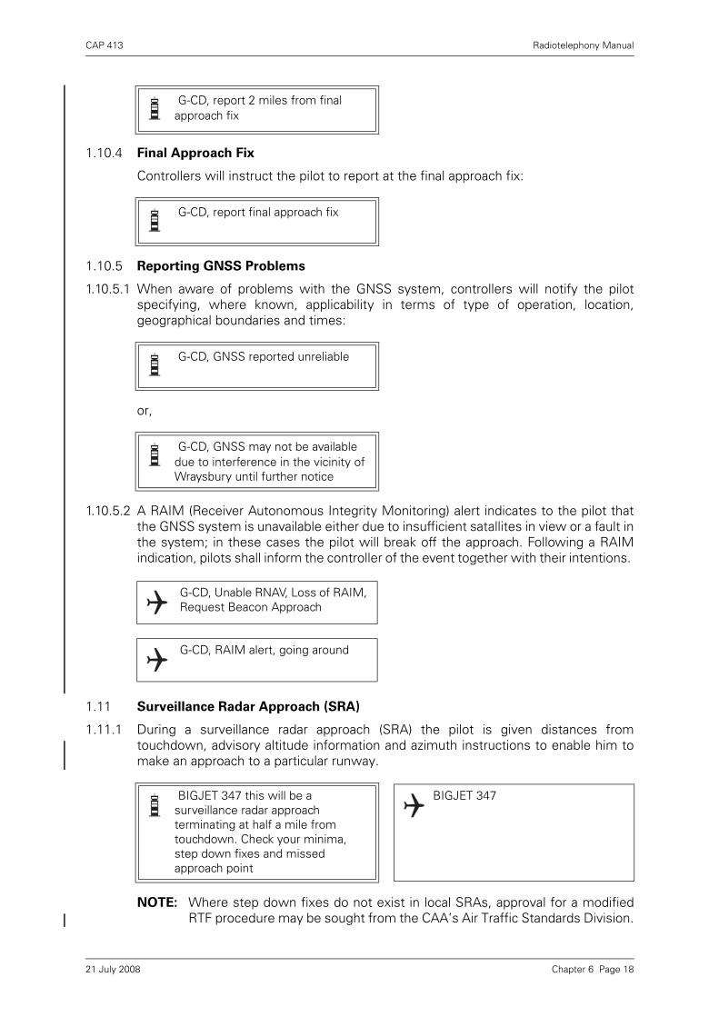
CAP 413 Radiotelephony Manual
1.10.4 Final Approach Fix
Controllers will instruct the pilot to report at the final approach fix:
1.10.5 Reporting GNSS Problems
1.10.5.1 When aware of problems with the GNSS system, controllers will notify the pilotspecifying, where known, applicability in terms of type of operation, location,geographical boundaries and times:
or,
1.10.5.2 A RAIM (Receiver Autonomous Integrity Monitoring) alert indicates to the pilot thatthe GNSS system is unavailable either due to insufficient satallites in view or a fault inthe system; in these cases the pilot will break off the approach. Following a RAIMindication, pilots shall inform the controller of the event together with their intentions.
1.11 Surveillance Radar Approach (SRA)
1.11.1 During a surveillance radar approach (SRA) the pilot is given distances fromtouchdown, advisory altitude information and azimuth instructions to enable him tomake an approach to a particular runway.
NOTE: Where step down fixes do not exist in local SRAs, approval for a modifiedRTF procedure may be sought from the CAA’s Air Traffic Standards Division.
G-CD, report 2 miles from final approach fix
G-CD, report final approach fix
G-CD, GNSS reported unreliable
G-CD, GNSS may not be available due to interference in the vicinity of Wraysbury until further notice
G-CD, Unable RNAV, Loss of RAIM, Request Beacon Approach
G-CD, RAIM alert, going around
BIGJET 347 this will be a surveillance radar approach terminating at half a mile from touchdown. Check your minima, step down fixes and missed approach point
BIGJET 347
Chapter 6 Page 1821 July 2008
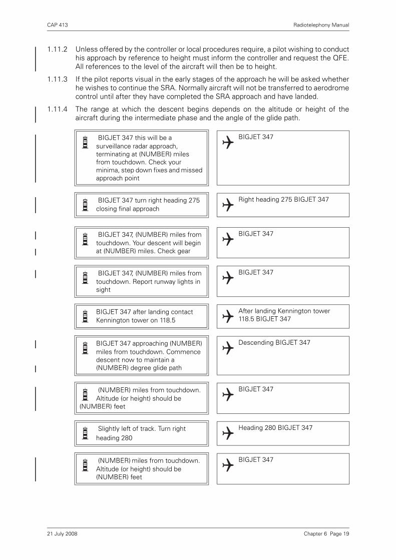
CAP 413 Radiotelephony Manual
1.11.2 Unless offered by the controller or local procedures require, a pilot wishing to conducthis approach by reference to height must inform the controller and request the QFE.All references to the level of the aircraft will then be to height.
1.11.3 If the pilot reports visual in the early stages of the approach he will be asked whetherhe wishes to continue the SRA. Normally aircraft will not be transferred to aerodromecontrol until after they have completed the SRA approach and have landed.
1.11.4 The range at which the descent begins depends on the altitude or height of theaircraft during the intermediate phase and the angle of the glide path.
BIGJET 347 this will be a surveillance radar approach, terminating at (NUMBER) miles from touchdown. Check your minima, step down fixes and missed approach point
BIGJET 347
BIGJET 347 turn right heading 275 closing final approach
Right heading 275 BIGJET 347
BIGJET 347, (NUMBER) miles from touchdown. Your descent will begin at (NUMBER) miles. Check gear
BIGJET 347
BIGJET 347, (NUMBER) miles from touchdown. Report runway lights in sight
BIGJET 347
BIGJET 347 after landing contact Kennington tower on 118.5
After landing Kennington tower 118.5 BIGJET 347
BIGJET 347 approaching (NUMBER) miles from touchdown. Commence descent now to maintain a (NUMBER) degree glide path
Descending BIGJET 347
(NUMBER) miles from touchdown. Altitude (or height) should be
(NUMBER) feet
BIGJET 347
Slightly left of track. Turn right heading 280
Heading 280 BIGJET 347
(NUMBER) miles from touchdown. Altitude (or height) should be (NUMBER) feet
BIGJET 347
Chapter 6 Page 1921 July 2008
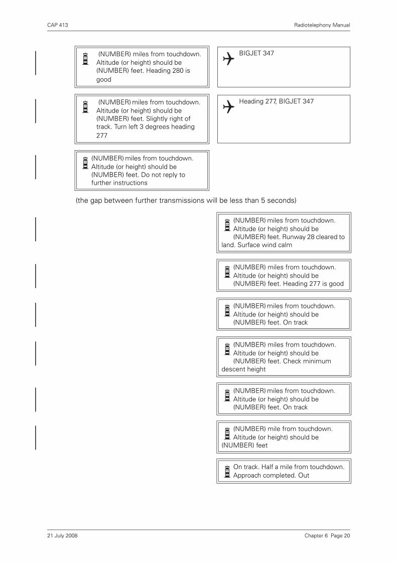
CAP 413 Radiotelephony Manual
(the gap between further transmissions will be less than 5 seconds)
(NUMBER) miles from touchdown. Altitude (or height) should be (NUMBER) feet. Heading 280 is good
BIGJET 347
(NUMBER) miles from touchdown. Altitude (or height) should be (NUMBER) feet. Slightly right of track. Turn left 3 degrees heading 277
Heading 277, BIGJET 347
(NUMBER) miles from touchdown. Altitude (or height) should be (NUMBER) feet. Do not reply to further instructions
(NUMBER) miles from touchdown. Altitude (or height) should be (NUMBER) feet. Runway 28 cleared to
land. Surface wind calm
(NUMBER) miles from touchdown. Altitude (or height) should be (NUMBER) feet. Heading 277 is good
(NUMBER) miles from touchdown. Altitude (or height) should be (NUMBER) feet. On track
(NUMBER) miles from touchdown. Altitude (or height) should be (NUMBER) feet. Check minimum
descent height
(NUMBER) miles from touchdown. Altitude (or height) should be (NUMBER) feet. On track
(NUMBER) mile from touchdown. Altitude (or height) should be
(NUMBER) feet
On track. Half a mile from touchdown. Approach completed. Out
Chapter 6 Page 2021 July 2008

CAP 413 Radiotelephony Manual
1.11.5 When the SRA terminates at 2 miles from touchdown the advisory level checks at halfmile intervals are omitted and pilots are expected to reply to all transmissions fromthe ground station.
1.11.6 Altitude/height checks below the category A aircraft OCA/OCH will be omitted.
1.12 Landing Altimeter Setting (QNE)
QNE is the indication which the altimeter will give on landing, at a particular time andplace, when the millibar scale is set to 1013.2 mb. QNE information may be used bypilots of aircraft whose altimeters cannot be set to below 950 mb. The QFE/QNEconversion will be calculated by ATC.
Example: QFE 947.6 Set 1013.2 on altimeter Altimeter will read 1842 ft on touchdown
1.13 PAR Approach
1.13.1 Pilots visiting military airfields may wish to undertake a PAR Approach (PrecisionApproach Radar). The following scenario assumes that G-RRRF has already beenidentified by Westbury Approach and is under an ATC service at 2500 ft on theRegional Pressure Setting.
Westbury Approach, G-RRRF request PAR
G-RF Westbury Approach, PAR for runway 27 approved, procedure minimum 300 ft
300 ft to land, G-RF
G-RF roger, set QFE 1001 descend to 1500 ft
1001 set, descend to height 1500 ft, G-RF
G-RF are you familiar with Westbury Missed Approach and Communication Failure Procedure
G-RF negative
G-RF in the event of a missed approach, climb straight ahead to 2300 ft and recall me on this frequency
In the event of a missed approach, climb straight ahead to 2300 ft and recall Westbury on this frequency, GRF
Chapter 6 Page 2121 July 2008

CAP 413 Radiotelephony Manual
G-RF correct. If radio contact lost and you are unable to continue this approach, climb to the safety height of 2300 ft and recall Westbury on this or any other published frequency
If radio contact lost, and I am unable to continue this approach, climb to the safety height of 2300 ft and recall Westbury on this or any other published frequency, G-RF
G-RF correct. Turn right heading 100 degrees downwind
Right heading 100 degrees G-RF
G-RF heading 100 degrees, maintaining 1500 ft
G-RF, cockpit checks report complete
G-RF cockpit checks complete
G-RF turn left heading 360 degrees base leg
Left heading 360 degrees, G-RF
G-RF heading 360 degrees G-RF turn left heading 310 degrees
Left heading 310 degrees, G-RF
G-RF heading 310 degrees G-RF turn left heading 265
Left heading 265, G-RF
G-RF, 8 miles, contact Westbury Talkdown on 123.325
Westbury Talkdown 123.325 G-RF
Chapter 6 Page 2221 July 2008

CAP 413 Radiotelephony Manual
Westbury Talkdown G-RRRF G-RRRF Westbury Talkdown identified, turn right heading 270, readback QFE
Right heading 270, QFE 1001 set G-RRRF
7 miles, correcting nicely. Do not acknowledge further instructions unless requested
6½ miles, slightly right of centreline, turn left heading 265
6 miles, correcting nicely approaching descent point
5½ miles
Turn right 3° heading 268
5 miles begin descent now for a 3° glidepath, on centreline
Turn right 2° heading 270, on centreline, slightly above glidepath
4½ miles on centreline, slightly above glidepath, correcting nicely
On glidepath, on centreline, heading 270
4 miles, slightly below glidepath, check gear, acknowledge
Gear down, G-RF
Turn right 3° heading 273, slightly left of centreline, slightly below glidepath, correcting nicely
Chapter 6 Page 2321 July 2008

CAP 413 Radiotelephony Manual
3½ miles on glidepath, slightly left of centreline, correcting nicely
Turn left 3° heading 270 on centreline
3 miles, cleared to land, surface wind 250 5, on glidepath, on centreline heading 270
Turn left 2° heading 268, on centreline, on glidepath
2½ miles, on centreline, on glidepath
2 miles, turn left 3° heading 265, slightly right of centreline, on glidepath
Slightly above glidepath, slightly right of centreline, correcting nicely, heading 265
1½ miles, slightly above glidepath, correcting nicely
Approaching decision height, on glidepath, on centreline, turn right 3° heading 268
1 mile, on glidepath, on centreline
Slightly above glidepath, on centreline
½ mile, on glidepath on centreline
G-RF over touchdown, contact Westbury Tower 132.850
Chapter 6 Page 2421 July 2008

CAP 413 Radiotelephony Manual
1.13.2 The following phrases may also be encountered during a PAR; further explanation ofsome of the terms employed are included in the Remarks column in the table below:
Table 1
Position Control to Aircraft Aircraft to Control Remarks
Initial approach G-RF Westbury, PAR Azimuth only for runway 27 approved, procedure minimum .... ft .... ft, G-RF
Employed when no glidepath information is available
Glidepath and rate of descent
Well above/below glidepath. Acknowledge G-RF
correcting rapidly
G-RF
Range .... miles Passed at ½ nm intervals. (RN pass ranges at 1/3 nm intervals
Heading Well/slightly left/right of centreline
correcting rapidly/slowly/nicely
Glidepath failure during PAR
Glidepath failure, the procedure minimum is .... ft– acknowledge G-RF G-RF
Procedure continues to published Missed Approach Point for AZ only approach
Undercarriage check Check gear, acknowledge
Gear down, G-RF Normally carried out between 3 and 4 nm from touchdown.
Not required for aircraft with fixed undercarriage
Clearance Final clearance delayed, continue approach
Break off this approach – acknowledge .... (further instructions as required) G-RF acknowledged
(repeat of any further instructions)
Indicating that required clearance may be forthcoming
Specific instructions and reasons will be passed
Chapter 6 Page 2521 July 2008
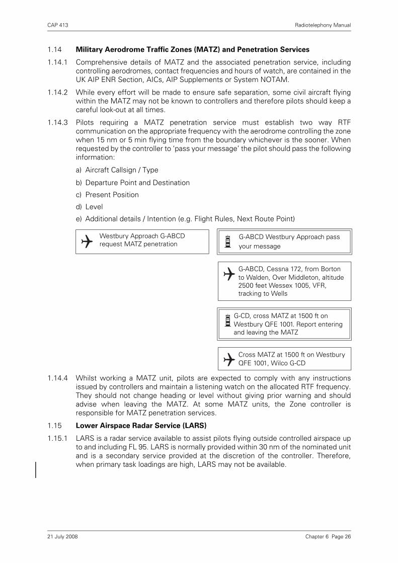
CAP 413 Radiotelephony Manual
1.14 Military Aerodrome Traffic Zones (MATZ) and Penetration Services
1.14.1 Comprehensive details of MATZ and the associated penetration service, includingcontrolling aerodromes, contact frequencies and hours of watch, are contained in theUK AIP ENR Section, AICs, AIP Supplements or System NOTAM.
1.14.2 While every effort will be made to ensure safe separation, some civil aircraft flyingwithin the MATZ may not be known to controllers and therefore pilots should keep acareful look-out at all times.
1.14.3 Pilots requiring a MATZ penetration service must establish two way RTFcommunication on the appropriate frequency with the aerodrome controlling the zonewhen 15 nm or 5 min flying time from the boundary whichever is the sooner. Whenrequested by the controller to ‘pass your message’ the pilot should pass the followinginformation:
a) Aircraft Callsign / Type
b) Departure Point and Destination
c) Present Position
d) Level
e) Additional details / Intention (e.g. Flight Rules, Next Route Point)
1.14.4 Whilst working a MATZ unit, pilots are expected to comply with any instructionsissued by controllers and maintain a listening watch on the allocated RTF frequency.They should not change heading or level without giving prior warning and shouldadvise when leaving the MATZ. At some MATZ units, the Zone controller isresponsible for MATZ penetration services.
1.15 Lower Airspace Radar Service (LARS)
1.15.1 LARS is a radar service available to assist pilots flying outside controlled airspace upto and including FL 95. LARS is normally provided within 30 nm of the nominated unitand is a secondary service provided at the discretion of the controller. Therefore,when primary task loadings are high, LARS may not be available.
Westbury Approach G-ABCD request MATZ penetration
G-ABCD Westbury Approach pass your message
G-ABCD, Cessna 172, from Borton to Walden, Over Middleton, altitude 2500 feet Wessex 1005, VFR, tracking to Wells
G-CD, cross MATZ at 1500 ft on Westbury QFE 1001. Report entering and leaving the MATZ
Cross MATZ at 1500 ft on Westbury QFE 1001, Wilco G-CD
Chapter 6 Page 2621 July 2008
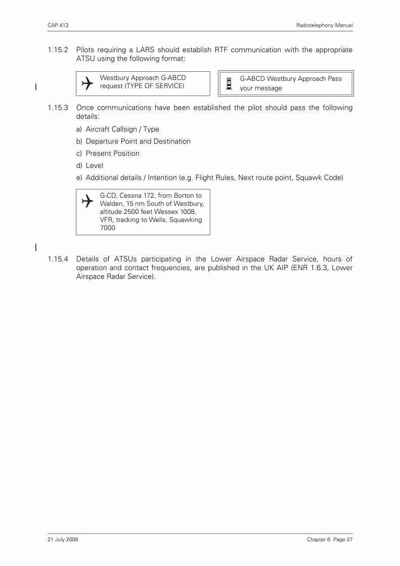
CAP 413 Radiotelephony Manual
1.15.2 Pilots requiring a LARS should establish RTF communication with the appropriateATSU using the following format:
1.15.3 Once communications have been established the pilot should pass the followingdetails:
a) Aircraft Callsign / Type
b) Departure Point and Destination
c) Present Position
d) Level
e) Additional details / Intention (e.g. Flight Rules, Next route point, Squawk Code)
1.15.4 Details of ATSUs participating in the Lower Airspace Radar Service, hours ofoperation and contact frequencies, are published in the UK AIP (ENR 1.6.3, LowerAirspace Radar Service).
Westbury Approach G-ABCD request (TYPE OF SERVICE)
G-ABCD Westbury Approach Pass your message
G-CD, Cessna 172, from Borton to Walden, 15 nm South of Westbury, altitude 2500 feet Wessex 1008, VFR, tracking to Wells, Squawking 7000
Chapter 6 Page 2721 July 2008

INTENTIONALLY LEFT BLANK

CAP 413 Radiotelephony Manual
Chapter 7 Area Phraseology
1 Area Control Service Phraseology
1.1 General
The following examples of phraseology are suitable for use at area control centresaccording to the requirements of the prevailing traffic situation.
1.2 Position Reporting
In order to assist in establishing separation, pilots may be instructed to provideadditional position report information as well as routine reports.
BIGJET 347 request descent BIGJET 347 maintain FL 280 expect descent after Marlow
Maintaining FL 280 BIGJET 347
BIGJET 347 descend FL 120. Cross Colinton FL 170 or above
Descend FL 120. Cross Colinton FL 170 or above BIGJET 347
BIGJET 347 are you able to cross Colinton at time 52
Affirm BIGJET 347
BIGJET 347 cross Colinton 52 or before
Cross Colinton 52 or before BIGJET 347
BIGJET 347 report Colinton BIGJET 347
BIGJET 347 Colinton 47 FL 170 descending FL 120, abeam KTN at 55
BIGJET 347
BIGJET 347 report 25 miles DME from Kennington
Wilco BIGJET 347
BIGJET 347 report your DME distance from Kennington
BIGJET 347 26 miles
Chapter 7 Page 121 July 2008
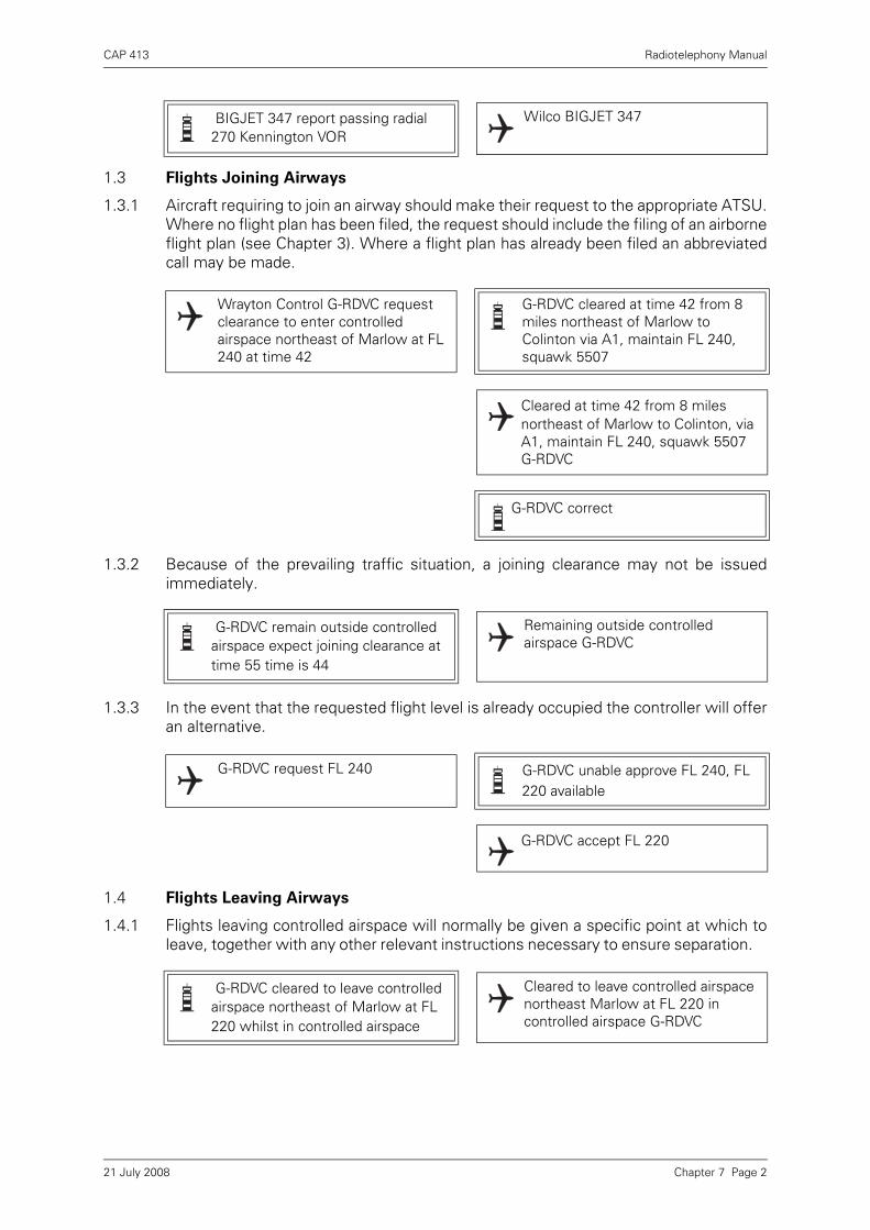
CAP 413 Radiotelephony Manual
1.3 Flights Joining Airways
1.3.1 Aircraft requiring to join an airway should make their request to the appropriate ATSU.Where no flight plan has been filed, the request should include the filing of an airborneflight plan (see Chapter 3). Where a flight plan has already been filed an abbreviatedcall may be made.
1.3.2 Because of the prevailing traffic situation, a joining clearance may not be issuedimmediately.
1.3.3 In the event that the requested flight level is already occupied the controller will offeran alternative.
1.4 Flights Leaving Airways
1.4.1 Flights leaving controlled airspace will normally be given a specific point at which toleave, together with any other relevant instructions necessary to ensure separation.
BIGJET 347 report passing radial 270 Kennington VOR
Wilco BIGJET 347
Wrayton Control G-RDVC request clearance to enter controlled airspace northeast of Marlow at FL 240 at time 42
G-RDVC cleared at time 42 from 8 miles northeast of Marlow to Colinton via A1, maintain FL 240, squawk 5507
Cleared at time 42 from 8 miles northeast of Marlow to Colinton, via A1, maintain FL 240, squawk 5507 G-RDVC
G-RDVC correct
G-RDVC remain outside controlled airspace expect joining clearance at time 55 time is 44
Remaining outside controlled airspace G-RDVC
G-RDVC request FL 240 G-RDVC unable approve FL 240, FL 220 available
G-RDVC accept FL 220
G-RDVC cleared to leave controlled airspace northeast of Marlow at FL 220 whilst in controlled airspace
Cleared to leave controlled airspace northeast Marlow at FL 220 in controlled airspace G-RDVC
Chapter 7 Page 221 July 2008
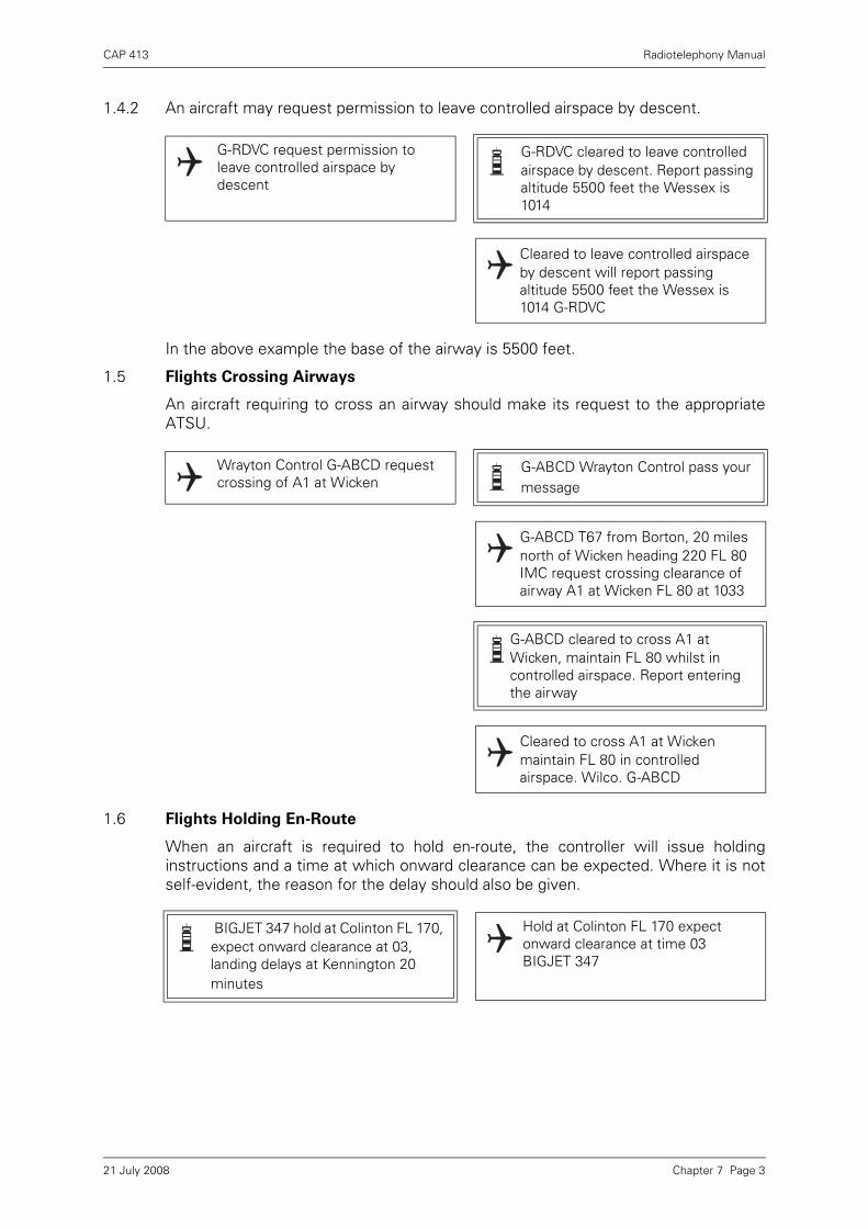
CAP 413 Radiotelephony Manual
1.4.2 An aircraft may request permission to leave controlled airspace by descent.
In the above example the base of the airway is 5500 feet.
1.5 Flights Crossing Airways
An aircraft requiring to cross an airway should make its request to the appropriateATSU.
1.6 Flights Holding En-Route
When an aircraft is required to hold en-route, the controller will issue holdinginstructions and a time at which onward clearance can be expected. Where it is notself-evident, the reason for the delay should also be given.
G-RDVC request permission to leave controlled airspace by descent
G-RDVC cleared to leave controlled airspace by descent. Report passing altitude 5500 feet the Wessex is 1014
Cleared to leave controlled airspace by descent will report passing altitude 5500 feet the Wessex is 1014 G-RDVC
Wrayton Control G-ABCD request crossing of A1 at Wicken
G-ABCD Wrayton Control pass your message
G-ABCD T67 from Borton, 20 miles north of Wicken heading 220 FL 80 IMC request crossing clearance of airway A1 at Wicken FL 80 at 1033
G-ABCD cleared to cross A1 at Wicken, maintain FL 80 whilst in controlled airspace. Report entering the airway
Cleared to cross A1 at Wicken maintain FL 80 in controlled airspace. Wilco. G-ABCD
BIGJET 347 hold at Colinton FL 170, expect onward clearance at 03, landing delays at Kennington 20 minutes
Hold at Colinton FL 170 expect onward clearance at time 03 BIGJET 347
Chapter 7 Page 321 July 2008

CAP 413 Radiotelephony Manual
1.7 Reduced Vertical Separation Minimum (RVSM) Phraseology
1.7.1 The following phraseology is applicable for RVSM operations:
NOTE: Should there be reason to believe that an aircraft's declared RVSM status isin doubt, then the controller shall ask the RVSM status in accordance with inthe table above.
Example: A non-RVSM compliant aircraft maintaining FL 350 making aninitial call on a new frequency:
Pilot: (callsign) MAINTAINING FL350, NEGATIVE RVSM
Table 1
MessagePhraseology
(italics indicates a pilot transmission)
To ascertain the RVSM approval status of a flight
CONFIRM RVSM APPROVED
Pilot indication of RVSM Approved status
Pilot indication of non RVSM approval status
AFFIRM RVSM
NEGATIVE RVSM (supplementary information e.g. State aircraft)
To deny ATC clearance into RVSM airspace UNABLE ISSUE CLEARANCE INTO RVSM AIRSPACE, MAINTAIN [or DESCEND TO or CLIMB TO] (level)
For the case of an individual aircraft reporting severe turbulence or other severe weather related phenomenon
UNABLE RVSM DUE TURBULENCE
The phraseology required for a pilot to communicate those circumstances which would cause an aircraft's equipment to degrade to below altimetry Minimum Aircraft Systems Performance Specification (MASPS) compliance levels
Note: The phrase is to be used to convey both the initial indication of the non-altimetry MASPS compliance and, henceforth, on initial contact on all frequencies within the lateral limits of the RVSM airspace until such time as the problem ceases to exist
UNABLE RVSM DUE EQUIPMENT
To request an aircraft provide information as soon as RVSM approved status has been regained or the pilot is ready to resume RVSM operations
REPORT ABLE TO RESUME RVSM
To request confirmation that an aircraft has regained RVSM approved status or the pilot is ready to resume RVSM operations
CONFIRM ABLE TO RESUME RVSM
The pilot shall communicate his/her ability to resume operation within the RVSM airspace after an equipment related contingency, or his/her ability to resume RVSM operations after a weather related contingency
READY TO RESUME RVSM
Chapter 7 Page 421 July 2008

CAP 413 Radiotelephony Manual
1.7.2 During operations in, or vertical transit through, reduced vertical separation minimum(RVSM) airspace with aircraft not approved for RVSM operations, pilots shall reportnon-approved status at initial call on any channel within RVSM airspace.
1.7.3 Air traffic controllers shall explicitly acknowledge receipt of messages from aircraftreporting RVSM non-approved status.
Chapter 7 Page 521 July 2008

INTENTIONALLY LEFT BLANK

CAP 413 Radiotelephony Manual
Chapter 8 Emergency Phraseology
1 Distress and Urgency Communication Procedures
1.1 Introduction
This Chapter describes the characteristics of the VHF International AeronauticalEmergency Service and the RTF procedures which should be used under theAeronautical Mobile Service during an emergency in the UK. Additional information ispublished in the UK AIP (GEN) section and AICs.
1.2 States of Emergency
1.2.1 The states of emergency are classified as follows:
a) Distress A condition of being threatened by serious and/or imminent danger andof requiring immediate assistance.
b) Urgency A condition concerning the safety of an aircraft or other vehicle, or ofsome person on board or within sight, but does not require immediate assistance.
1.2.2 The pilot should make the appropriate emergency call as follows:
a) Distress ‘MAYDAY, MAYDAY, MAYDAY’
b) Urgency ‘PAN PAN, PAN PAN, PAN PAN’
1.3 VHF Emergency Service
1.3.1 The UK has two Distress and Diversion (D&D) Sections located at the London andScottish Area Control Centres. They are manned by RAF control staff who areassisted in the provision of an emergency service on the International AeronauticalEmergency Frequency 121.5 MHz by suitably equipped civil and military units andcertain HM Coastguard stations. The service is available continuously to pilots flyingwithin UK airspace who are in distress, in urgent need of assistance, or experiencingdifficulties (i.e. temporarily unsure of position) which could lead to a state ofemergency. The service may also be available for practices provided that no actualemergency is in progress on the UHF or VHF distress frequencies. More informationon the emergency service for civil pilots can be found in the UK AIP (GEN).
1.3.2 The primary role of the D&D Sections is to provide military and civil pilots with anemergency aid and position fixer service. Autotriangulation (DF) coverage on 121.5MHz is available over most of the London FIR above 2000 ft amsl to aircraft flying tothe east and south of Manchester. In respect of other civil aircraft incidents on VHFthey rely for position fixing on DF bearing information obtained by telephone fromexternal units equipped with VDF. This fixing procedure takes time and may requireseveral minutes of concentrated activity because it involves the manual plotting onto1:250,000 charts of the bearings received. The quality of the position fixes isdetermined by the availability of VDF bearings, and thus, depends largely on theheight of an aircraft and its distance from the VDF stations. The coverage of the VHFfixing service is limited below 3000 ft amsl; indeed, the ability to locate aircraft at lowaltitude by the use of VDF may be severely inhibited (because of the effects of highground) over much of Scotland, Wales and SW England. In circumstances where121.5 MHz DF data is lacking, the controller’s ability to assist a pilot who is uncertainof his position is very limited, and will depend on such factors as the availability of SSRinformation and the amount and accuracy of the information provided by the pilotabout his route, last known position and observed landmarks.
Chapter 8 Page 121 July 2008
CAP 413 Radiotelephony Manual
1.3.3 Certain UK aerodromes can also offer civil pilots an effective emergencycommunications and aid service. Some maintain a continuous watch on 121.5 MHz,but not all are equipped with VDF or SSR. Others do not normally listen out on 121.5MHz but they do have VDF and may be asked by the Emergency Controller to provideDF bearing information on an aircraft, and other assistance. Where a bearing isrequired for fixing purposes from an airfield which has VDF but not on 121.5 MHz, theEmergency Controller may instruct the pilot to change temporarily to the frequencyon which VDF is available.
1.4 VHF Emergency Service – General Procedures
1.4.1 Pilots should address their emergency calls on 121.5 MHz to ‘London Centre’ whensouth of N55°, and ‘Scottish Centre’ when north of N55°. If doubt exists about theappropriate centre, it is not necessary to address a specific station. Once two-waycommunication has been established, pilots should not leave 121.5 MHz withouttelling the controller. The use of special D&D Sections at the ACCs in the provision ofemergency services is unique to the UK. Detailed information on related UK Searchand Rescue (SAR) procedures is contained in the GEN Section of the UK AIP.
1.4.2 Pilots are urged – in their own interests – to request assistance from the emergencyservice as soon as there is any doubt about the safe conduct of their flight. Even then,the provision of assistance may be delayed if a pilot does not pass clear details of hisdifficulties and requirements, using the international standard RTF prefix ‘MAYDAY,MAYDAY, MAYDAY’ or ‘PAN PAN, PAN PAN, PAN PAN’ as appropriate. For example,a vague request from a pilot for ‘confirmation of position’ is unlikely to be accordedas much priority as would be given to a statement that he is lost. If, subsequent tothe transmission of a ‘MAYDAY’ or ‘PAN’, a pilot considers the problem not to be asserious as first thought and priority attention is no longer required, the emergencycondition may be cancelled at the pilot’s discretion. It is invariably preferable for pilotsbelieving themselves to be facing emergency situations to declare them as early aspossible and then cancel later if they decide the situation allows.
1.4.3 If a pilot is already in communication with a civil or military ATSU, before theemergency arises, assistance should be requested from the controller on thefrequency in use. In this case, any SSR code setting previously assigned by ATC(other than the Conspicuity Code 7000) should be retained until instructions arereceived to change the code setting.
1.4.4 If, however, the pilot is not in direct communication with an ATSU and the aircraft isequipped with an SSR transponder it should be switched, preferably before theemergency call is made, to Emergency Code 7700, with Mode C if available. If thetransponding aircraft is high enough to be within secondary radar cover, the selectionof the Emergency 7700 Code will alert the Emergency Controller to the presence ofan incident by means of an audio and visual warning. The received SSR plot will showthe precise location of the aircraft on the controller’s radar display, and will thenobviate the need for the emergency controller to carry out the more time-consumingmanual aircraft position plotting procedure. Information on SSR operating procedures,including Special Purpose Codes 7700 (Emergency), 7600 (Radio Failure) and 7500(Hijack or Other Act of Violence) are detailed in the ENR Section of the UK AIP.
1.4.5 If no acknowledgement of the distress or urgency message is made by the stationaddressed by the aircraft, other stations shall render assistance. Due to the nature ofdistress and urgency situations, the originator of messages addressed to an aircraftin distress or urgency condition shall restrict to the minimum the number and volumeand content of such messages as required by the condition.
Chapter 8 Page 221 July 2008
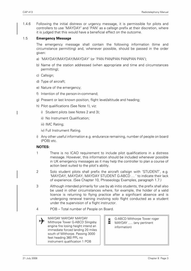
CAP 413 Radiotelephony Manual
1.4.6 Following the initial distress or urgency message, it is permissible for pilots andcontrollers to use ‘MAYDAY’ and ‘PAN’ as a callsign prefix at their discretion, whereit is judged that this would have a beneficial effect on the outcome.
1.5 Emergency Message
The emergency message shall contain the following information (time andcircumstance permitting) and, whenever possible, should be passed in the ordergiven:
a) ‘MAYDAY/MAYDAY/MAYDAY’ (or ‘PAN PAN/PAN PAN/PAN PAN’);
b) Name of the station addressed (when appropriate and time and circumstancespermitting);
c) Callsign;
d) Type of aircraft;
e) Nature of the emergency;
f) Intention of the person-in-command;
g) Present or last known position, flight level/altitude and heading;
h) Pilot qualifications (See Note 1), viz:
i) Student pilots (see Notes 2 and 3);
ii) No Instrument Qualification;
iii) IMC Rating;
iv) Full Instrument Rating.
i) Any other useful information e.g. endurance remaining, number of people on board(POB) etc.
NOTES:
1 There is no ICAO requirement to include pilot qualifications in a distressmessage. However, this information should be included whenever possiblein UK emergency messages as it may help the controller to plan a course ofaction best suited to the pilot’s ability.
2 Solo student pilots shall prefix the aircraft callsign with ‘STUDENT’, e.g.‘MAYDAY, MAYDAY, MAYDAY STUDENT G-ABCD … ‘ to indicate their lackof experience. (See Chapter 10, Phraseology Examples, paragraph 1.7.)
3 Although intended primarily for use by ab initio students, the prefix shall alsobe used in other circumstances where, for example, the holder of a validlicence is returning to flying practice after a significant absence and isundergoing renewal training involving solo flight conducted as a studentunder the supervision of a flight instructor.
4 POB – Total number of People on Board.
MAYDAY MAYDAY MAYDAY Milthorpe Tower G-ABCD Slingsby engine fire losing height intend an immediate forced landing 20 miles south of Milthorpe. Passing 3000 feet heading 360 PPL no instrument qualification 1 POB
G-ABCD Milthorpe Tower roger MAYDAY ..... (any pertinent information)
Chapter 8 Page 321 July 2008
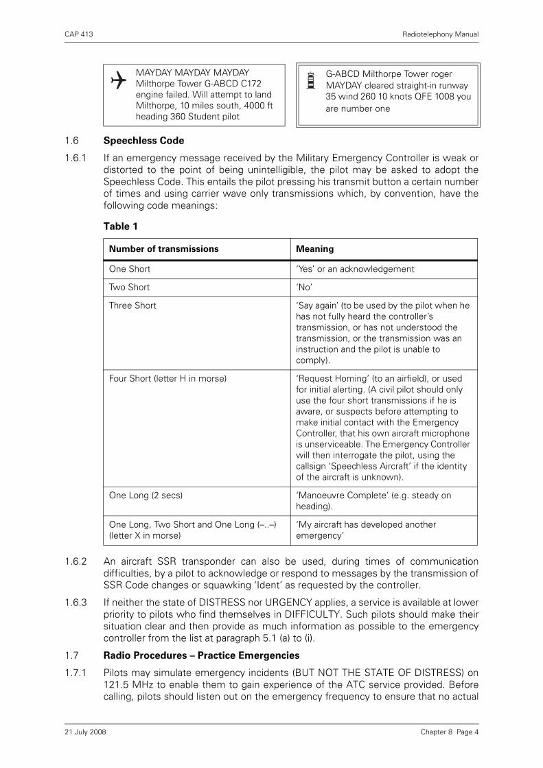
CAP 413 Radiotelephony Manual
1.6 Speechless Code
1.6.1 If an emergency message received by the Military Emergency Controller is weak ordistorted to the point of being unintelligible, the pilot may be asked to adopt theSpeechless Code. This entails the pilot pressing his transmit button a certain numberof times and using carrier wave only transmissions which, by convention, have thefollowing code meanings:
1.6.2 An aircraft SSR transponder can also be used, during times of communicationdifficulties, by a pilot to acknowledge or respond to messages by the transmission ofSSR Code changes or squawking ‘Ident’ as requested by the controller.
1.6.3 If neither the state of DISTRESS nor URGENCY applies, a service is available at lowerpriority to pilots who find themselves in DIFFICULTY. Such pilots should make theirsituation clear and then provide as much information as possible to the emergencycontroller from the list at paragraph 5.1 (a) to (i).
1.7 Radio Procedures – Practice Emergencies
1.7.1 Pilots may simulate emergency incidents (BUT NOT THE STATE OF DISTRESS) on121.5 MHz to enable them to gain experience of the ATC service provided. Beforecalling, pilots should listen out on the emergency frequency to ensure that no actual
MAYDAY MAYDAY MAYDAY Milthorpe Tower G-ABCD C172 engine failed. Will attempt to land Milthorpe, 10 miles south, 4000 ft heading 360 Student pilot
G-ABCD Milthorpe Tower roger MAYDAY cleared straight-in runway 35 wind 260 10 knots QFE 1008 you are number one
Table 1
Number of transmissions Meaning
One Short ‘Yes’ or an acknowledgement
Two Short ‘No’
Three Short ‘Say again’ (to be used by the pilot when he has not fully heard the controller’s transmission, or has not understood the transmission, or the transmission was an instruction and the pilot is unable to comply).
Four Short (letter H in morse) ‘Request Homing’ (to an airfield), or used for initial alerting. (A civil pilot should only use the four short transmissions if he is aware, or suspects before attempting to make initial contact with the Emergency Controller, that his own aircraft microphone is unserviceable. The Emergency Controller will then interrogate the pilot, using the callsign ‘Speechless Aircraft’ if the identity of the aircraft is unknown).
One Long (2 secs) ‘Manoeuvre Complete’ (e.g. steady on heading).
One Long, Two Short and One Long (–..–) (letter X in morse)
‘My aircraft has developed another emergency’
Chapter 8 Page 421 July 2008
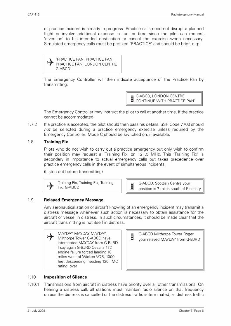
CAP 413 Radiotelephony Manual
or practice incident is already in progress. Practice calls need not disrupt a plannedflight or involve additional expense in fuel or time since the pilot can request‘diversion’ to his intended destination or cancel the exercise when necessary.Simulated emergency calls must be prefixed ‘PRACTICE’ and should be brief, e.g:
The Emergency Controller will then indicate acceptance of the Practice Pan bytransmitting:
The Emergency Controller may instruct the pilot to call at another time, if the practicecannot be accommodated.
1.7.2 If a practice is accepted, the pilot should then pass his details. SSR Code 7700 shouldnot be selected during a practice emergency exercise unless required by theEmergency Controller. Mode C should be switched on, if available.
1.8 Training Fix
Pilots who do not wish to carry out a practice emergency but only wish to confirmtheir position may request a ‘Training Fix’ on 121.5 MHz. This ‘Training Fix’ issecondary in importance to actual emergency calls but takes precedence overpractice emergency calls in the event of simultaneous incidents.
(Listen out before transmitting)
1.9 Relayed Emergency Message
Any aeronautical station or aircraft knowing of an emergency incident may transmit adistress message whenever such action is necessary to obtain assistance for theaircraft or vessel in distress. In such circumstances, it should be made clear that theaircraft transmitting is not itself in distress.
1.10 Imposition of Silence
1.10.1 Transmissions from aircraft in distress have priority over all other transmissions. Onhearing a distress call, all stations must maintain radio silence on that frequencyunless the distress is cancelled or the distress traffic is terminated; all distress traffic
‘PRACTICE PAN, PRACTICE PAN, PRACTICE PAN, LONDON CENTRE G-ABCD’
G-ABCD, LONDON CENTRE CONTINUE WITH PRACTICE PAN’
Training Fix, Training Fix, Training Fix, G-ABCD
G-ABCD, Scottish Centre your position is 7 miles south of Pitlochry
MAYDAY MAYDAY MAYDAY Milthorpe Tower G-ABCD have intercepted MAYDAY from G-BJRD I say again G-BJRD Cessna 172 engine failure forced landing 10 miles west of Wicken VOR, 1000 feet descending, heading 120, IMC rating, over
G-ABCD Milthorpe Tower Roger your relayed MAYDAY from G-BJRD
Chapter 8 Page 521 July 2008
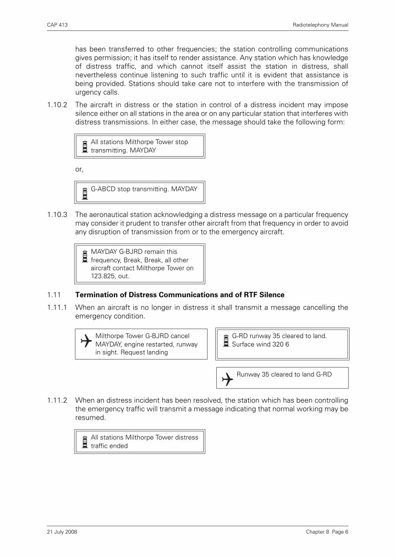
CAP 413 Radiotelephony Manual
has been transferred to other frequencies; the station controlling communicationsgives permission; it has itself to render assistance. Any station which has knowledgeof distress traffic, and which cannot itself assist the station in distress, shallnevertheless continue listening to such traffic until it is evident that assistance isbeing provided. Stations should take care not to interfere with the transmission ofurgency calls.
1.10.2 The aircraft in distress or the station in control of a distress incident may imposesilence either on all stations in the area or on any particular station that interferes withdistress transmissions. In either case, the message should take the following form:
or,
1.10.3 The aeronautical station acknowledging a distress message on a particular frequencymay consider it prudent to transfer other aircraft from that frequency in order to avoidany disruption of transmission from or to the emergency aircraft.
1.11 Termination of Distress Communications and of RTF Silence
1.11.1 When an aircraft is no longer in distress it shall transmit a message cancelling theemergency condition.
1.11.2 When an distress incident has been resolved, the station which has been controllingthe emergency traffic will transmit a message indicating that normal working may beresumed.
All stations Milthorpe Tower stop transmitting. MAYDAY
G-ABCD stop transmitting. MAYDAY
MAYDAY G-BJRD remain this frequency, Break, Break, all other aircraft contact Milthorpe Tower on 123.825, out.
Milthorpe Tower G-BJRD cancel MAYDAY, engine restarted, runway in sight. Request landing
G-RD runway 35 cleared to land. Surface wind 320 6
Runway 35 cleared to land G-RD
All stations Milthorpe Tower distress traffic ended
Chapter 8 Page 621 July 2008

CAP 413 Radiotelephony Manual
Chapter 9 Miscellaneous Phraseology
1 Other Communications
1.1 Vortex Wake
1.1.1 ATC will provide the appropriate spacing between IFR flights but, if a pilot elects toexecute a visual approach, or is arriving as a VFR flight, it is his responsibility toprovide adequate spacing, although ATC will pass the appropriate distance.
1.1.2 For departing flights ATC will issue take-off clearance when the required vortex wakespacing minima will be achieved. The minima to be applied at the time the aircraft areairborne is dependent on aircraft sequence, vortex wake categories, and runwaydeparture configuration.
1.2 Wind Shear
When wind shear is forecast or is reported by aircraft, ATC will warn other aircraft untilsuch time as aircraft report the phenomenon no longer exists.
1.3 AIRPROX Reporting
1.3.1 An AIRPROX Report should be made by any pilot flying in the United Kingdom FlightInformation Region, the Upper Flight Information Region or Shanwick Oceanic Areawhen in his opinion, the distance between aircraft as well as their relative positionsand speed have been such that the safety of the aircraft involved was or may havebeen compromised.
1.3.2 The initial report is made by RTF to the ATSU in communication with the aircraftexcept that if the controllers workload is such that he is not able to accept the reportthe pilot will be requested to file details after landing.
1.3.3 The Pilot’s RTF report should commence with words ‘AIRPROX REPORT’ and shouldinclude the following items:
Aircraft Callsign
SSR Code
G-BJCD caution vortex wake the recommended spacing is (number) miles
G-BJCD
G-BJCD, Ready G-BJCD Hold position, (number) minutes delay due to vortex wake
Holding G-BJCD
G-CD at 0745 a departing B757 reported windshear at 800 feet. Airspeed loss 20 kts, strong right drift
Chapter 9 Page 121 July 2008
CAP 413 Radiotelephony Manual
Position of AIRPROX
Aircraft heading
Flight level, altitude or height
Altimeter setting
Aircraft attitude (level/climbing/descending/turning)
Weather conditions
Date and time (UTC) of the AIRPROX
Description of other aircraft
First sighting distance and details of flight paths of reporting and reported aircraft.
1.3.4 RTF AIRPROX reports are to be confirmed in writing within seven days of the incidentto allow follow up action to be taken. (See UK AIP ENR Section.)
1.4 Oil Pollution Reporting
Pilots sighting substantial patches of oil are requested to make reports by RTF to theATSU with whom they are in communication or the appropriate FIS in order thataction can be taken.
The RTF reports should contain the following:
‘OIL POLLUTION REPORT’ or ‘POLLUTION REPORT’
. . . Time and date (if required) pollution was observed and identify of reporting aircraft.
. . . Position and extent of pollution
. . . Tide, windspeed and direction
. . . Weather conditions and Sea state
. . . Characteristics of pollution
. . . Name and nationality or description, including any distinctive markings, of anyvessel seen discharging oil or other harmful substances; also estimated course andspeed of vessel and if pollution is observed ahead of the discharging ship and theestimated length of pollution in her wake
. . . Identity of any other vessels in the immediate vicinity
. . . Whether photographs taken.
1.5 Interceptions by Military Aircraft
Pilots are warned that should they become involved in an interception by militaryaircraft they should follow the international procedures as detailed in the UK AIP ENRSection.
1.6 Aircraft Operating Agency Messages
1.6.1 Introduction
An aeronautical radio station which is licensed and established for companyoperational control communications (OPC) may be used only for communication withcompany aircraft or aircraft for which the company is the operating agency. A radiooperator’s certificate of competence issued by the UK CAA is not required for the useof this radio station.
Chapter 9 Page 221 July 2008
CAP 413 Radiotelephony Manual
1.6.2 Limitations
Personnel authorised to use an aircraft operating agency radio must not holdthemselves out as providing an air traffic control service, i.e. they must not passinstructions to aircraft which could be construed in any way to be such a service.Similar constraints apply with regard to flight information services provided by anAFISO for specific ground movements at aerodromes. Flight safety messages mustbe confined to messages originated by the agency which are of immediate concernto an aircraft in flight or just about to depart. This may include meteorologicalinformation.
1.6.3 Aircraft operating agency radio stations may only transmit and receive flight regularityand flight safety messages.
1.6.4 Air traffic service units using direct pilot-controller communication channels shall onlybe required to handle flight regularity messages provided this can be achievedwithout interference with their primary role and no other channels are available for thehandling of such messages.
1.6.5 Flight regularity messages comprise the following:
a) Messages regarding the operation or maintenance of facilities essential for thesafety or regularity of aircraft operation.
b) Messages concerning the servicing of aircraft.
c) Instructions to aircraft operating agency representatives concerning changes inrequirements for passengers and crew caused by unavoidable deviations fromnormal operating schedules. Individual requirements of passengers or crew arenot admissible in this type of message.
d) Messages concerning non-routine landings to be made by the aircraft.
e) Messages concerning aircraft parts and materials urgently required.
f) Messages concerning changes in aircraft operating schedules.
1.6.6 Flight safety messages shall comprise the following:
a) Movement and control messages (e.g. flight plans, clearances),
b) Messages originated by an aircraft operating agency, or by an aircraft, ofimmediate concern to an aircraft in flight,
c) Meteorological advice of immediate concern to an aircraft in flight or about todepart (individually communicated or for broadcast),
d) Other messages concerning aircraft in flight or about to depart.
1.6.7 It is permissible for aircraft operating agency messages to be handled by theaerodrome communication facility provided this can be achieved without interferencewith its primary role and no other channels are available for the handling of suchmessages.
1.6.8 Public correspondence messages are not permitted on VHF frequencies in theaeronautical mobile service.
1.7 8.33 kHz Phraseology
1.7.1 As a solution to severe VHF spectrum congestion, ICAO has split the VHFcommunications band from 25 kHz to 8.33 kHz channel spacing.
Chapter 9 Page 321 July 2008
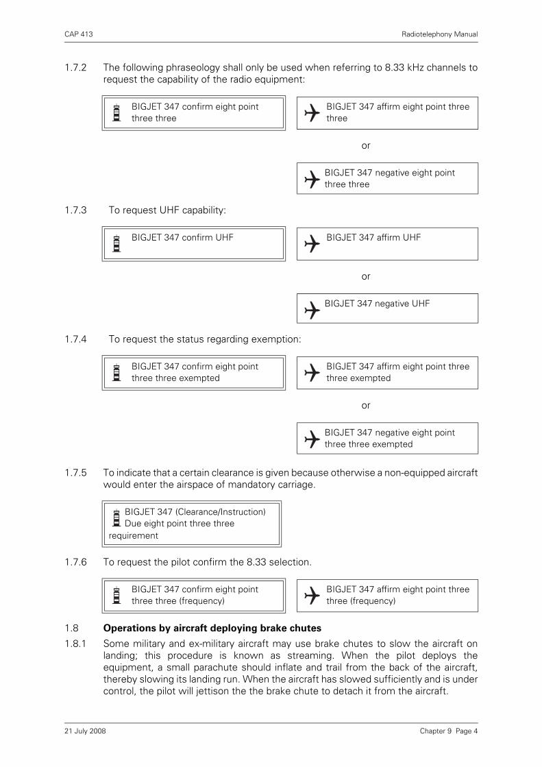
CAP 413 Radiotelephony Manual
1.7.2 The following phraseology shall only be used when referring to 8.33 kHz channels torequest the capability of the radio equipment:
or
1.7.3 To request UHF capability:
or
1.7.4 To request the status regarding exemption:
or
1.7.5 To indicate that a certain clearance is given because otherwise a non-equipped aircraftwould enter the airspace of mandatory carriage.
1.7.6 To request the pilot confirm the 8.33 selection.
1.8 Operations by aircraft deploying brake chutes
1.8.1 Some military and ex-military aircraft may use brake chutes to slow the aircraft onlanding; this procedure is known as streaming. When the pilot deploys theequipment, a small parachute should inflate and trail from the back of the aircraft,thereby slowing its landing run. When the aircraft has slowed sufficiently and is undercontrol, the pilot will jettison the the brake chute to detach it from the aircraft.
BIGJET 347 confirm eight point three three
BIGJET 347 affirm eight point three three
BIGJET 347 negative eight point three three
BIGJET 347 confirm UHF BIGJET 347 affirm UHF
BIGJET 347 negative UHF
BIGJET 347 confirm eight point three three exempted
BIGJET 347 affirm eight point three three exempted
BIGJET 347 negative eight point three three exempted
BIGJET 347 (Clearance/Instruction) Due eight point three three
requirement
BIGJET 347 confirm eight point three three (frequency)
BIGJET 347 affirm eight point three three (frequency)
Chapter 9 Page 421 July 2008

CAP 413 Radiotelephony Manual
1.8.2 It is important that pilots who intend to deploy a brake chute advise the aerodromestaff so that appropriate ground procedures can be put in place in order to reduce theflight safety hazard posed to other aerodrome users. Additionally, in certaincircumstances, a brake chute may fail to deploy correctly and it is important that,where possible, the pilot is advised of the failure.
1.8.3 Operations by military and ex-military aircraft that use brake chutes commonly takeplace at aerodromes with AFISO or AGCS. The following examples show thephraseology suitable for use by personnel providing AFISO, AGCS or aerodromecontrol.
1.8.4 When the aircraft is downwind or on final to land, the pilot should advise the ATSU ifhe intends to deploy the brake chute using the word 'stream' or 'streaming' toindicate that the chute will be deployed:
1.8.5 If there is any doubt about the pilot’s intentions, the ATSU should ascertain whetheror not the pilot intends to deploy a brake chute:
1.8.6 To ensure that other pilots using the aerodrome are aware of the intention to stream,an all-stations broadcast may be made as follows:
1.8.7 On landing, it is important that, where possible, the pilot is kept informed if the chutedoes not deploy in the correct manner. The following phraseology may be usedaccording to the situation:
NOTE: Pilots must be aware the ATS will not always be able to advise themalfunction of a chute and that the pilot remains responsible for the safetyof the aircraft.
1.8.8 Unless otherwise instructed, or where there is a designated area for jettisoning thechute, the pilot should jettison the chute at a suitable location, taking account of thewind speed and direction, preferably when the aircraft has vacated the runway. Theterm ‘drop’ or ‘dropping’ should be used in communications relating to jettisoning thechute as shown in the examples below:
Wrayton Information Redship 1 downwind to land and stream
Redship 1 Wrayton Information roger report final
Redship 1 Wrayton confirm streaming
Affirm streaming Redship 1
All Stations Wrayton Information aircraft on final will be deploying a brake chute
“Callsign streamed and candled” To be used when the chute is seen to deploy but fails to inflate.
“Callsign negative stream” To be used when the chute fails to deploy.
Wrayton Information dropping the chute now Redship 1
Redship 1 roger
Chapter 9 Page 521 July 2008

CAP 413 Radiotelephony Manual
or
Redship 1 Wrayton Information vacate via link Charlie and drop the chute after passing holding point C3
Vacate via link C and drop the chute after passing holding point C3 Redship 1
Chapter 9 Page 621 July 2008

CAP 413 Radiotelephony Manual
Chapter 10 Phraseology Examples
1 Examples of Types of Flights
1.1 Introduction
An example of an IFR flight from one major airport to another, and an example of aVFR flight from a provincial aerodrome to a landing site, are given in graphic form inthis chapter. The latter then changes to an IFR flight on departure again to illustratethe differences between RAS and RIS (see Chapter 6 and Chapter 10 paragraph1.3.5). The agencies are described in Figure 4.
Figure 1 Diagram Key
BIGJET 347 G-ABCD
GROUND/TOWER/APPROACH WRAYTON ACC (CONTROL/INFORMATION)
Chapter 10 Page 121 July 2008

CAP 413 Radiotelephony Manual
1.2 An IFR Flight
1.2.1 Start up
NOTE: The word 'APPROVED' is used - not 'CLEARED'.
1.2.2 ATC Clearance
Figure 2 IFR – Start Up Approval
Stourton Ground BIGJET 347. Radio check 118.3
Station calling Stourton Ground say again your callsign
Stourton Ground BIGJET 347 radio check 118.3
BIGJET 347 Stourton Ground readability 5
Ground BIGJET 347, stand 24, information bravo, QNH 1011 request start up
BIGJET 347 start up approved
Figure 3 IFR – ATC Clearance
BIGJET 347 is cleared to Kennington via A1 at FL 60, request level change enroute, squawk 5501
Cleared to Kennington at FL 60, request level change enroute, squawk 5501 BIGJET 347
BIGJET 347 correct
Chapter 10 Page 221 July 2008
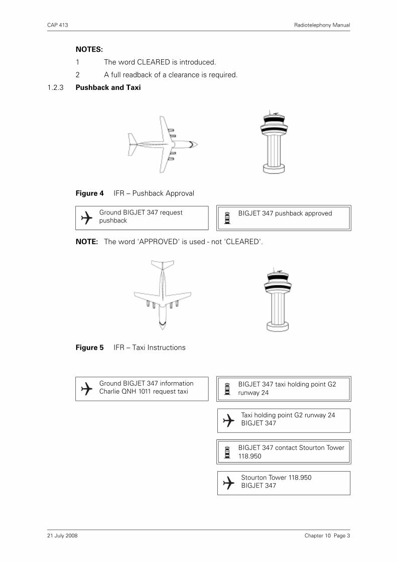
CAP 413 Radiotelephony Manual
NOTES:
1 The word CLEARED is introduced.
2 A full readback of a clearance is required.
1.2.3 Pushback and Taxi
NOTE: The word 'APPROVED' is used - not 'CLEARED'.
Figure 4 IFR – Pushback Approval
Ground BIGJET 347 request pushback
BIGJET 347 pushback approved
Figure 5 IFR – Taxi Instructions
Ground BIGJET 347 information Charlie QNH 1011 request taxi
BIGJET 347 taxi holding point G2 runway 24
Taxi holding point G2 runway 24 BIGJET 347
BIGJET 347 contact Stourton Tower 118.950
Stourton Tower 118.950 BIGJET 347
Chapter 10 Page 321 July 2008

CAP 413 Radiotelephony Manual
1.2.4 Pre-departure and Take-off
NOTES:
1 ‘DEPARTURE’ employed and not ‘TAKE-OFF’.
2 ‘CLEARED’ is not used in these cases – see next ‘Notes’.
3 Full readback is required for instructions to ENTER, LAND, TAKE-OFF ON,BACKTRACK, HOLD SHORT OF, OR CROSS a runway.
4 ‘LINE UP AND WAIT’ (plus reason) is employed; ‘LINE UP’ (only) may also beused.
Figure 6 IFR – Departure Instructions and Line-up (i)
Stourton Tower BIGJET 347 ready for departure
BIGJET 347 Stourton Tower after departure climb straight ahead until passing altitude 2500 feet
After departure climb straight ahead until passing altitude 2500 feet BIGJET 347
BIGJET 347 line up and wait. Vehicle crossing upwind end of runway
Line up and wait. BIGJET 347
Chapter 10 Page 421 July 2008

CAP 413 Radiotelephony Manual
NOTES: 1 TAKE-OFF – these words are only used when an aircraft is cleared for TAKE-OFF.
2 TAKE-OFF clearance requires readback.
3 Use of CLEAR is restricted to:
i) ATC clearances.
ii) Departure and Approach instructions.
iii) Take-off and landing clearances.
NOTE: Full readback of frequency change.
Figure 7 IFR – Take-off Clearance
BIGJET 347 cleared for take-off surface wind calm
Cleared for take-off BIGJET 347
Figure 8 IFR – Airborne Report
BIGJET 347 contact Wrayton control 129.1
Wrayton Control 129.1 BIGJET 347
Chapter 10 Page 521 July 2008
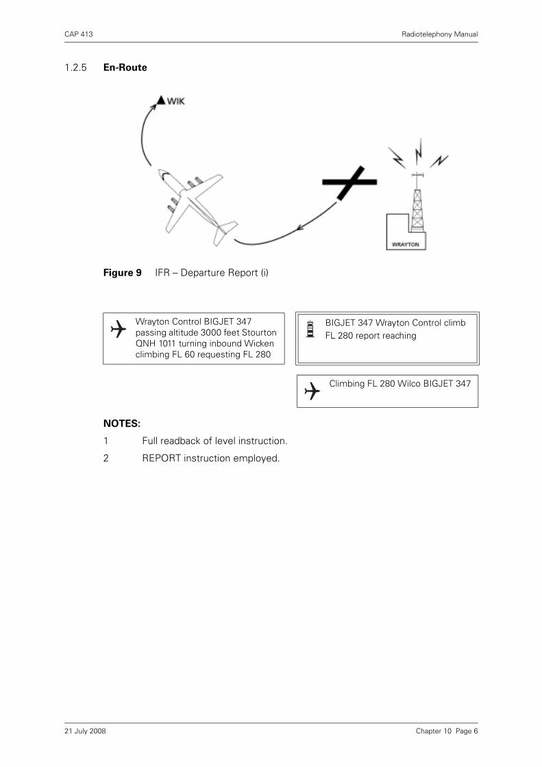
CAP 413 Radiotelephony Manual
1.2.5 En-Route
NOTES:
1 Full readback of level instruction.
2 REPORT instruction employed.
Figure 9 IFR – Departure Report (i)
Wrayton Control BIGJET 347 passing altitude 3000 feet Stourton QNH 1011 turning inbound Wicken climbing FL 60 requesting FL 280
BIGJET 347 Wrayton Control climb FL 280 report reaching
Climbing FL 280 Wilco BIGJET 347
Chapter 10 Page 621 July 2008
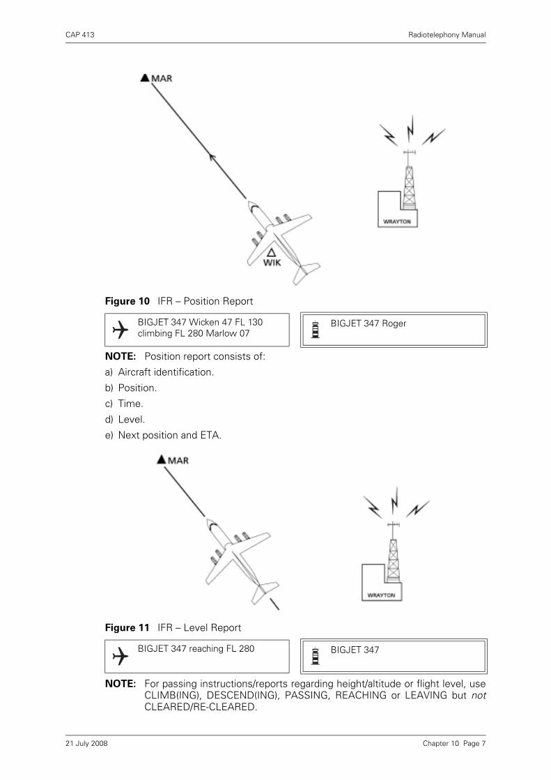
CAP 413 Radiotelephony Manual
NOTE: Position report consists of:
a) Aircraft identification.
b) Position.
c) Time.
d) Level.
e) Next position and ETA.
NOTE: For passing instructions/reports regarding height/altitude or flight level, useCLIMB(ING), DESCEND(ING), PASSING, REACHING or LEAVING but notCLEARED/RE-CLEARED.
Figure 10 IFR – Position Report
BIGJET 347 Wicken 47 FL 130 climbing FL 280 Marlow 07
BIGJET 347 Roger
Figure 11 IFR – Level Report
BIGJET 347 reaching FL 280 BIGJET 347
Chapter 10 Page 721 July 2008

CAP 413 Radiotelephony Manual
Figure 12 IFR – Position Report
BIGJET 347 Marlow 08 FL 280 Colinton 48
BIGJET 347
Figure 13 IFR – Descent Clearance
BIGJET 347 request descent BIGJET 347 descend FL 120 cross Colinton FL 170 or above
Descending FL 120 will cross Colinton FL 170 or above BIGJET 347
Chapter 10 Page 821 July 2008

CAP 413 Radiotelephony Manual
NOTE: AFFIRM/NEGATIVE are used when a question requires a direct answer.
Figure 14 IFR – ATC Request and Instruction
BIGJET 347 report your level BIGJET 347 passing FL 225
BIGJET 347 Roger. Are you able to cross Colinton at time 52
Affirm. BIGJET 347
BIGJET 347 cross Colinton 52 or later
Cross Colinton 52 or later BIGJET 347
Chapter 10 Page 921 July 2008
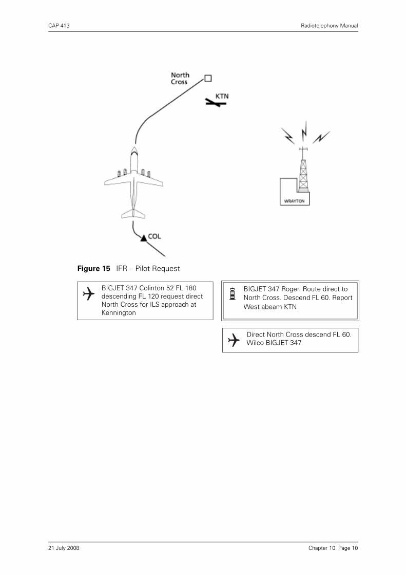
CAP 413 Radiotelephony Manual
Figure 15 IFR – Pilot Request
BIGJET 347 Colinton 52 FL 180 descending FL 120 request direct North Cross for ILS approach at Kennington
BIGJET 347 Roger. Route direct to North Cross. Descend FL 60. Report West abeam KTN
Direct North Cross descend FL 60. Wilco BIGJET 347
Chapter 10 Page 1021 July 2008

CAP 413 Radiotelephony Manual
NOTE: FL 100 spoken as “flight level WUN HUN DRED”
Figure 16 IFR – Descent to FL 100
BIGJET 347 West abeam Kennington 03 FL 100 descending FL 60 North Cross 11
BIGJET 347 Roger. Contact Kennington Approach 119.750
Kennington Approach 119.750 BIGJET 347
Chapter 10 Page 1121 July 2008
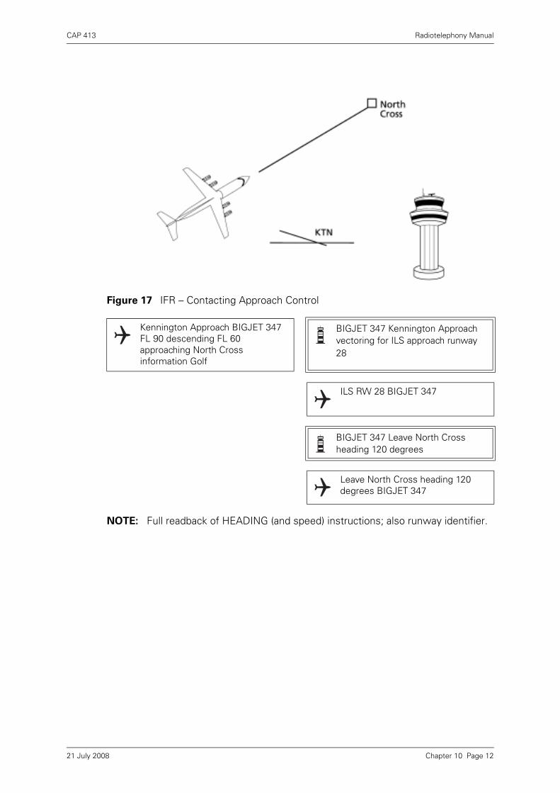
CAP 413 Radiotelephony Manual
NOTE: Full readback of HEADING (and speed) instructions; also runway identifier.
Figure 17 IFR – Contacting Approach Control
Kennington Approach BIGJET 347 FL 90 descending FL 60 approaching North Cross information Golf
BIGJET 347 Kennington Approach vectoring for ILS approach runway 28
ILS RW 28 BIGJET 347
BIGJET 347 Leave North Cross heading 120 degrees
Leave North Cross heading 120 degrees BIGJET 347
Chapter 10 Page 1221 July 2008

CAP 413 Radiotelephony Manual
Figure 18 IFR – Vectoring for Approach
BIGJET 347 North Cross FL 60 heading 120 degrees
BIGJET 347 descend to altitude 2500 feet QNH 1011
Descend to altitude 2500 feet QNH 1011 BIGJET 347
BIGJET 347 position 10 miles northeast of Kennington
BIGJET 347
BIGJET 347 turn right heading 190 degrees base leg 14 miles northeast of Kennington
Right heading 190 degrees BIGJET 347
Chapter 10 Page 1321 July 2008

CAP 413 Radiotelephony Manual
Figure 19 IFR – Intercepting the Localiser
BIGJET 347 turn right heading 240 degrees
Right heading 240 degrees BIGJET 347
BIGJET 347 closing final approach track from the right 12 miles from touchdown
BIGJET 347
BIGJET 347 closing the localiser from the right, report established
Wilco BIGJET 347
Chapter 10 Page 1421 July 2008

CAP 413 Radiotelephony Manual
NOTE: Surface wind: ‘Degrees’ and ‘Knots’ may be omitted.
Figure 20 IFR – Landing Clearance
BIGJET 347 localiser established BIGJET 347 descend on the ILS QFE 1008
QFE 1008, wilco BIGJET 347
BIGJET 347 contact Kennington Tower 118.925
Tower 118.925 BIGJET 347
Kennington Tower BIGJET 347 long final RW 28
BIGJET 347 Kennington Tower runway 28 cleared to land surface wind 240 10
Runway 28 cleared to land BIGJET 347
Chapter 10 Page 1521 July 2008

CAP 413 Radiotelephony Manual
NOTE: VACATE runway and not CLEAR runway.
Figure 21 IFR – Vacate the Runway
BIGJET 347 vacate convenient right Vacate right BIGJET 347
Figure 22 IFR – Runway Vacated
BIGJET 347 runway vacated
Chapter 10 Page 1621 July 2008

CAP 413 Radiotelephony Manual
1.3 A VFR/IFR Flight
1.3.1 This particular example is aimed at the pilot flying outside controlled airspace underservices provided by the military in the UK (Westbury) to show the slight differencesthat exist from civil ATS as portrayed in previous chapters.
1.3.2 Engine Start and Departure Information
Figure 23 VFR – Start up and Taxi
Borton Tower G-ABCD radio check 118.7
G-ABCD Borton Tower readability 5
Borton Tower G-ABCD Slingsby T67 starting, request departure information
G-CD departure runway 24 surface wind 220 6, QNH 990 millibars temperature +6 dew point +3
Runway 24 QNH 997 millibars G-CD
G-CD negative. QNH 990 millibars
QNH 990 millibars G-CD
Borton Tower G-ABCD, T67 at the south side hangars request taxi for VFR flight to Walden
G-CD taxi holding point G1 runway 24 via taxiway Charlie QNH 990 millibars
Holding point G1 runway 24 via taxiway Charlie QNH 990 millibars, request surface wind G-CD
G-CD surface wind calm
G-CD request departure on runway 14
G-CD taxi holding point A1 runway 14
Taxi holding point A1 runway 14 G-CD
Chapter 10 Page 1721 July 2008

CAP 413 Radiotelephony Manual
1.3.3 Pre-departure and Take-off
NOTES:
1 DEPARTURE used not TAKE-OFF.
2 APPROVED used not CLEARED.
3 Full readback of departure clearance.
4 Runway identified as in this case it is not the runway in use.
5 Readback of take-off clearance.
Figure 24 VFR – Departure Instructions and Take-off Clearance
G-CD ready for departure request left turnout heading 330 degrees
G-CD, left turn approved. After departure climb not above altitude 2500 feet until reaching the zone boundary
Left turn approved. Not above altitude 2500 feet until zone boundary G-CD
G-CD runway 14 cleared for take-off surface wind 220 4
Runway 14 cleared for take-off G-CD
Chapter 10 Page 1821 July 2008

CAP 413 Radiotelephony Manual
1.3.4 Post Departure Flight
NOTES:
1 REPORT introduced.
2 CHANGING TO announces intention to change frequency.
3 Transmission of WESSEX Regional Pressure Setting is limited to regionalname and pressure.
Figure 25 VFR – Departure Report
G-CD contact Borton Approach 118.750
Borton Approach 118.750 G-CD
Borton Approach G-ABCD airborne runway 14 turning left heading 330 degrees climbing to altitude 2500 feet QNH 990 millibars, en-route Walden
G-CD Roger. Report reaching 2500 feet
Wilco G-CD
G-CD reaching altitude 2500 feet G-CD Roger report at the zone boundary
Wilco G-CD
G-CD zone boundary changing to Wrayton Information 125.750
G-CD Roger, the Wessex is 988 millibars
The Wessex is 988 millibars G-CD
Chapter 10 Page 1921 July 2008
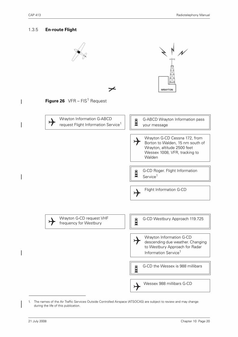
CAP 413 Radiotelephony Manual
1.3.5 En-route Flight
1
Figure 26 VFR – FIS1 Request
Wrayton Information G-ABCD request Flight Information Service1
G-ABCD Wrayton Information pass your message
Wrayton G-CD Cessna 172, from Borton to Walden, 15 nm south of Wrayton, altitude 2500 feet Wessex 1008, VFR, tracking to Walden
G-CD Roger. Flight Information
Service1
Flight Information G-CD
1. The names of the Air Traffic Services Outside Controlled Airspace (ATSOCAS) are subject to review and may change during the life of this publication.
Wrayton G-CD request VHF frequency for Westbury
G-CD Westbury Approach 119.725
Wrayton Information G-CD descending due weather. Changing to Westbury Approach for Radar Information Service1
G-CD the Wessex is 988 millibars
Wessex 988 millibars G-CD
Chapter 10 Page 2021 July 2008
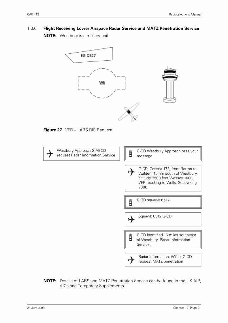
CAP 413 Radiotelephony Manual
1.3.6 Flight Receiving Lower Airspace Radar Service and MATZ Penetration Service
NOTE: Westbury is a military unit.
NOTE: Details of LARS and MATZ Penetration Service can be found in the UK AIP,AICs and Temporary Supplements.
Figure 27 VFR – LARS RIS Request
Westbury Approach G-ABCD request Radar Information Service
G-CD Westbury Approach pass your message
G-CD, Cessna 172, from Borton to Walden, 15 nm south of Westbury, altitude 2500 feet Wessex 1008, VFR, tracking to Wells, Squawking 7000
G-CD squawk 6512
Squawk 6512 G-CD
G-CD identified 16 miles southeast of Westbury. Radar Information Service.
Radar Information, Wilco. G-CD request MATZ penetration
Chapter 10 Page 2121 July 2008
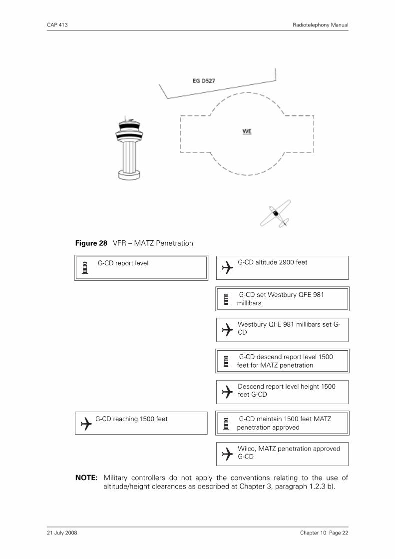
CAP 413 Radiotelephony Manual
NOTE: Military controllers do not apply the conventions relating to the use ofaltitude/height clearances as described at Chapter 3, paragraph 1.2.3 b).
Figure 28 VFR – MATZ Penetration
G-CD report level G-CD altitude 2900 feet
G-CD set Westbury QFE 981 millibars
Westbury QFE 981 millibars set G-CD
G-CD descend report level 1500 feet for MATZ penetration
Descend report level height 1500 feet G-CD
G-CD reaching 1500 feet G-CD maintain 1500 feet MATZ penetration approved
Wilco, MATZ penetration approved G-CD
Chapter 10 Page 2221 July 2008

CAP 413 Radiotelephony Manual
Figure 29 VFR – Join Request
G-CD entering MATZ limited warning of traffic from ahead as you approach my radar overhead
G-CD Roger. Request join for one visual circuit
G-CD Roger. Standby
G-CD one visual circuit approved maintain 1500 feet to overhead. Do you have the field in sight?
Maintain 1500 feet to overhead. G-CD has the field in sight
G-CD roger. Runway 27 right hand circuit height 1000 feet QFE 981 millibars
Runway 27 right hand circuit height 1000 feet QFE 981 millibars G-CD
G-CD request POB
1 POB G-CD
G-CD contact Westbury Tower 132.850
Westbury Tower 132.850 G-CD
Chapter 10 Page 2321 July 2008

CAP 413 Radiotelephony Manual
NOTES:
1 The question of landing fees etc. is not addressed in this scenario.
2 Circuit direction is only given when circuit is not left-hand.
3 Military units employ QFE in the circuit area, the instrument pattern and forMATZ penetration.
4 POB – Total number of People on Board.
Chapter 10 Page 2421 July 2008
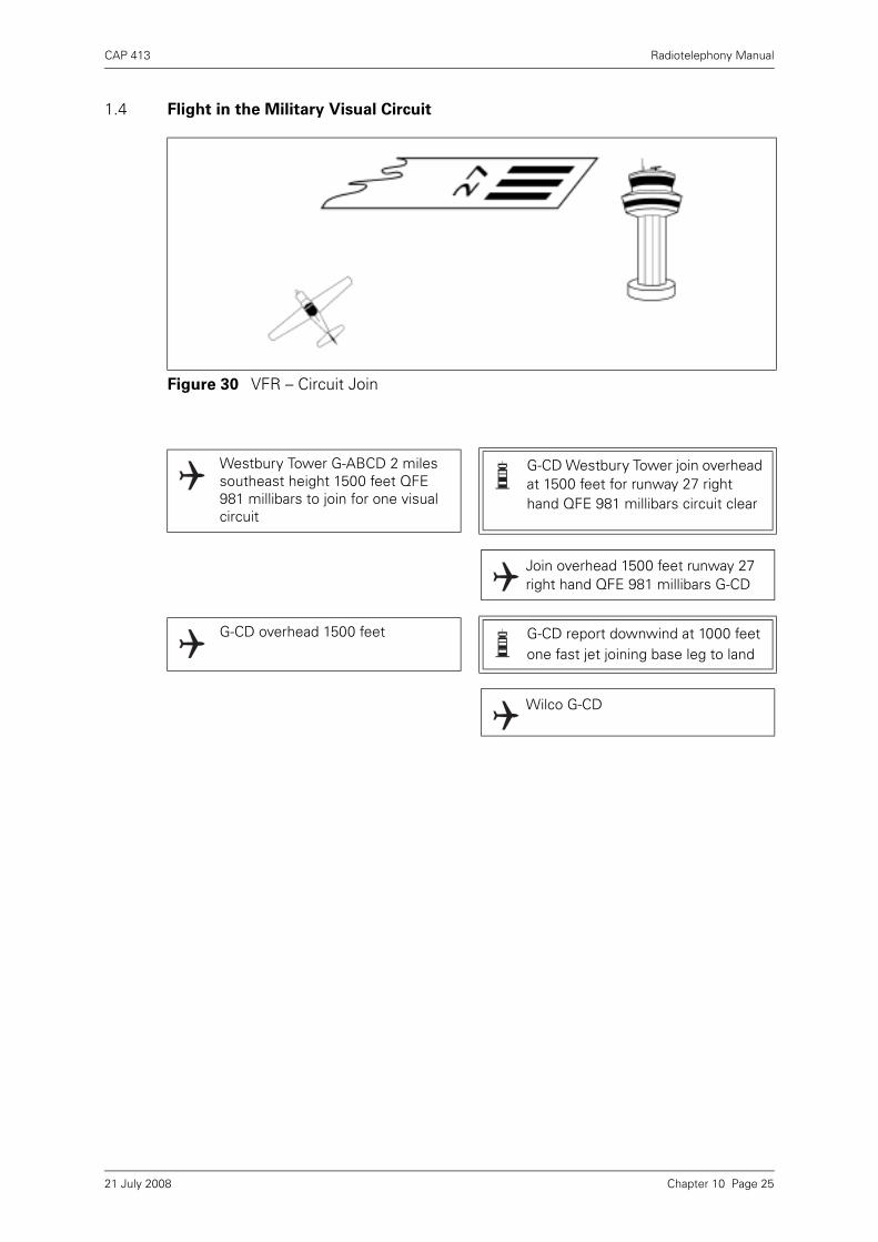
CAP 413 Radiotelephony Manual
1.4 Flight in the Military Visual Circuit
Figure 30 VFR – Circuit Join
Westbury Tower G-ABCD 2 miles southeast height 1500 feet QFE 981 millibars to join for one visual circuit
G-CD Westbury Tower join overhead at 1500 feet for runway 27 right hand QFE 981 millibars circuit clear
Join overhead 1500 feet runway 27 right hand QFE 981 millibars G-CD
G-CD overhead 1500 feet G-CD report downwind at 1000 feet one fast jet joining base leg to land
Wilco G-CD
Chapter 10 Page 2521 July 2008

CAP 413 Radiotelephony Manual
NOTES:
1 Downwind report is made abeam upwind end of runway. Aircraft intentionsare stated here.
2 ‘Final’ call is made just before turning base leg.
3 Military (jet) circuits tend to be relatively tight and are more oval-shaped.
4 Military use ‘two in’, ‘three in’ etc. for number of aircraft present in the visualcircuit.
Figure 31 Military Visual Circuit Pattern
Chapter 10 Page 2621 July 2008
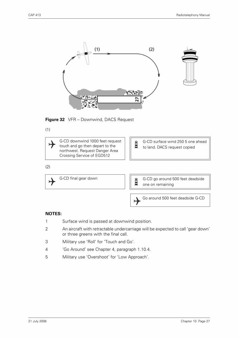
CAP 413 Radiotelephony Manual
(1)
(2)
NOTES:
1 Surface wind is passed at downwind position.
2 An aircraft with retractable undercarriage will be expected to call ‘gear down’or three greens with the final call.
3 Military use ‘Roll’ for ‘Touch and Go’.
4 ‘Go Around’ see Chapter 4, paragraph 1.10.4.
5 Military use ‘Overshoot’ for ‘Low Approach’.
Figure 32 VFR – Downwind, DACS Request
G-CD downwind 1000 feet request touch and go then depart to the northwest. Request Danger Area Crossing Service of EGD512
G-CD surface wind 250 5 one ahead to land. DACS request copied
G-CD final gear down G-CD go around 500 feet deadside one on remaining
Go around 500 feet deadside G-CD
Chapter 10 Page 2721 July 2008

CAP 413 Radiotelephony Manual
NOTE: Full readback of clearance and frequency change.
Figure 33 IFR – Departure Instructions (ii)
G-CD at upwind end of runway turn right heading 295 climb to 2000 feet QFE 981 millibars
Upwind end of runway right heading 295 climb to height 2000 feet QFE 981 millibars G-CD
Figure 34 IFR – Departure Report (ii)
G-CD heading 295 climbing to height 2000 feet
G-CD contact Westbury Approach 119.725
Westbury Approach 119.725 G-CD
Chapter 10 Page 2821 July 2008

CAP 413 Radiotelephony Manual
1.5 Flight Receiving Lower Airspace Radar Service (LARS) and Danger Area
Crossing Service (DACS)
NOTES:
1 AFFIRM used.
2 Military controllers use ‘MAINTAIN’ heading.
Figure 35 VFR – Requesting RAS
Westbury Approach G-ABCD heading 295 maintaining height 2000 feet QFE 981 millibars now IFR requesting Radar Advisory Service
G-CD Westbury Approach squawk ident. What is your requested level?
Ident G-CD. Request FL 45
G-CD identified, Radar Advisory Service, EGD527 Loudwater active will you accept a re-route?
Radar Advisory, affirm G-CD
G-CD maintain heading 295 climb FL 45
Heading 295 climbing FL 45 G-CD
Chapter 10 Page 2921 July 2008
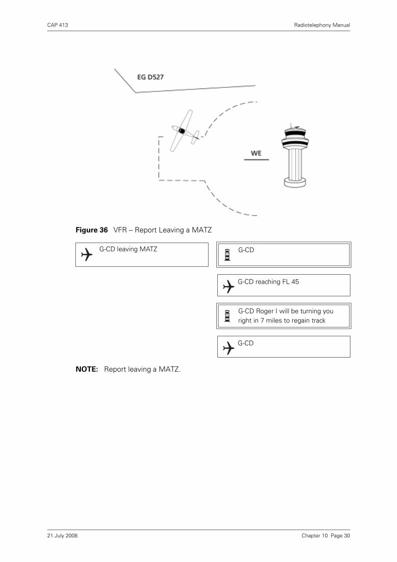
CAP 413 Radiotelephony Manual
NOTE: Report leaving a MATZ.
Figure 36 VFR – Report Leaving a MATZ
G-CD leaving MATZ G-CD
G-CD reaching FL 45
G-CD Roger I will be turning you right in 7 miles to regain track
G-CD
Chapter 10 Page 3021 July 2008

CAP 413 Radiotelephony Manual
1.6 Military Safety Broadcast - Securité
Military ground stations may commence a broadcast message with ‘SECURITÉSECURITÉ SECURITÉ’ (SEC-URI-TAY spoken three times) to inform all traffic that themessage contains information affecting safety, but not an emergency situation.Aircraft acknowledgement is not required, however aircraft may contact the groundstation to obtain further details.
Figure 37 Securité Broadcast
SECURITÉ SECURITÉ SECURITÉ, All traffic, Westbury Approach, D527 now active for live firing, surface to 2500 feet
Chapter 10 Page 3121 July 2008

CAP 413 Radiotelephony Manual
1.7 Callsign Prefix - ‘STUDENT’
1.7.1 On initial contact with Air Traffic Service Units (ATSUs) (including ATC centres andaerodromes providing an ATC service, an Aerodrome FIS (AFIS) or an AGCS), studentpilots who do not yet hold a licence and who are flying solo as part of their training areto prefix the aircraft callsign with the word “STUDENT”1. Once acknowledged, it willnot normally be necessary for student pilots to use the prefix in subsequenttransmissions until making initial contact with other ATSUs, unless they feel they arebeing instructed to do something with which they are unfamiliar.
1.7.2 ATS personnel will acknowledge the initial call, again using the prefix, and can beexpected, in so far as is practicable, to make due allowance for the limited experienceand ability of student pilots in determining the pace and complexity of instructionsand/or information which are subsequently passed.
1.7.3 A solo student pilot experiencing an emergency and communicating with a militaryunit or the D&D Section shall use the ‘STUDENT’ prefix with the aircraft callsign aspart of the distress or urgency message. A military ground station or the D&D sectionreceiving a distress or urgency message from a student pilot may use this informationon pilot experience to render the most appropriate assistance. (See also Chapter 8,Emergency Phraseology, paragraph 1.5.)
1. Although intended primarily for use by ab initio students, the prefix shall also be used in other circumstances where, for example, the holder of a valid licence is returning to flying practice after a significant absence and is undergoing renewal training involving solo flight conducted as a student under the supervision of a flight instructor.
MAYDAY MAYDAY MAYDAYWRAYTON CENTRESTUDENT G-ABCDPiper CherokeeLost Above CloudAltitude 3000 feet Heading EastEndurance 1 hour
STUDENT G-ABCDRoger MAYDAY …(any pertinent information)
Figure 38 Callsign Prefix ‘STUDENT’
Chapter 10 Page 3221 July 2008

CAP 413 Radiotelephony Manual
1.8 Flight Receiving Avoiding Action
NOTES:
1 This type of avoiding action when under Radar Advisory is given at thecontroller’s discretion for late sighting/pop-up traffic.
2 An unknown traffic call can be expected as follows: G-CD unknown traffic 11o’clock 6 miles crossing left to right no height, if not sighted turn left heading230 degrees.
Figure 39 Avoiding Action
G-CD avoiding action, turn left heading 230 degrees pop-up traffic was 12 o’clock 6 miles no height reciprocal heading
Left heading 230 degrees G-CD
Figure 40 Clear of Traffic
G-CD clear of traffic, turn right heading 340 degrees direct for Walden
Right heading 340 degrees. Request change to Wrayton Information 125.750 G-CD
G-CD squawk 7000 Freecall Wrayton Information 125.750
Squawk 7000 G-CD
Chapter 10 Page 3321 July 2008

CAP 413 Radiotelephony Manual
1.9 Flight Receiving En-Route Flight Information Service
Figure 41 VFR – En-route Reply to Pass Your Mesage
Wrayton Information G-ABCD request Flight Information Service
G-ABCD Wrayton Information pass your message
G-CD, Cessna 172, from Borton to Walden, 15 nm south of Westbury, altitude 2500 feet Wessex 1008, VFR tracking to Wells, request Walden weather
G-CD Roger Flight Information Service, standby for weather
Flight Information Service, G-CD
G-CD Walden weather available, are you ready to copy?
Affirm G-CD
G-CD Walden 0950 weather runway 27, surface wind calm, visibility 10 kilometres, nil weather, few at 4000 feet, scattered at 8000 feet, QNH 989 millibars temperature +4. Dew point +1
G-CD Roger, changing to Wrayton on 121.5 for Practice PAN
G-CD
Chapter 10 Page 3421 July 2008
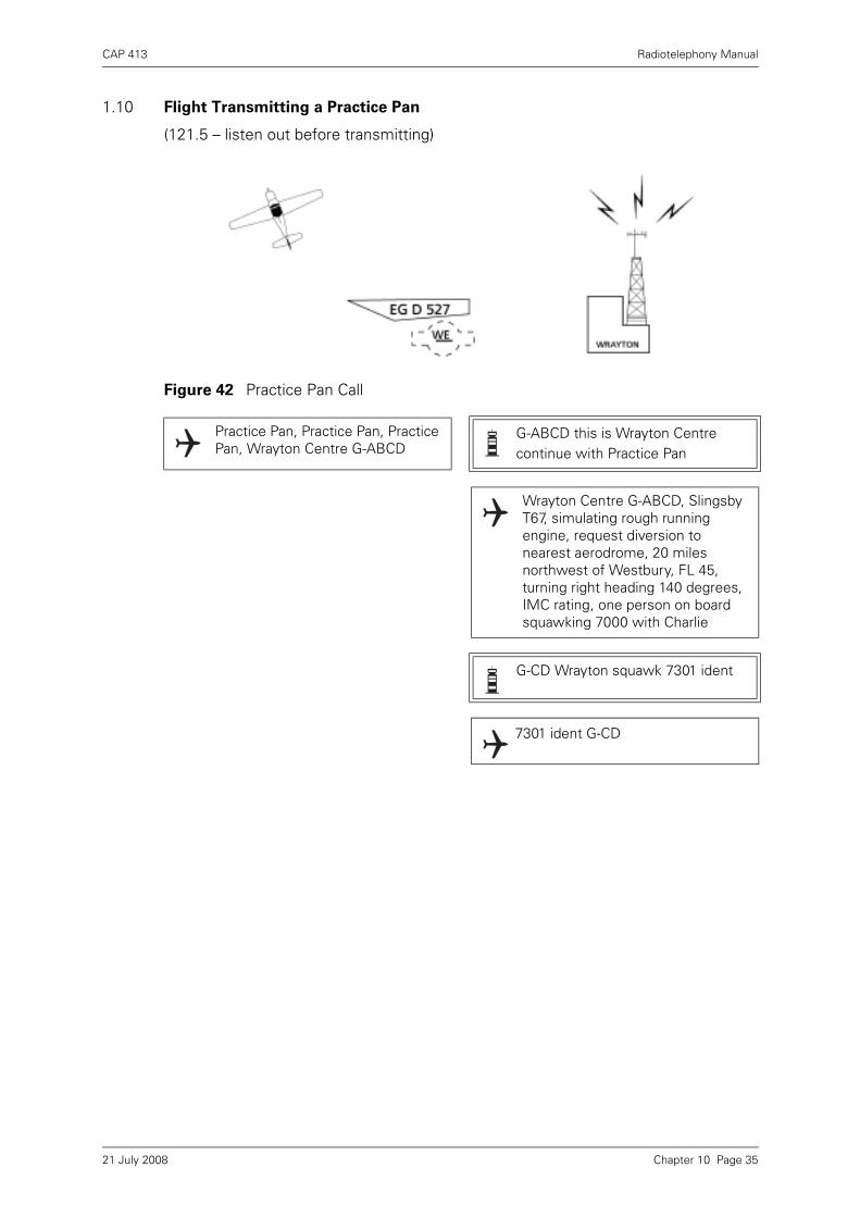
CAP 413 Radiotelephony Manual
1.10 Flight Transmitting a Practice Pan
(121.5 – listen out before transmitting)
Figure 42 Practice Pan Call
Practice Pan, Practice Pan, Practice Pan, Wrayton Centre G-ABCD
G-ABCD this is Wrayton Centre continue with Practice Pan
Wrayton Centre G-ABCD, Slingsby T67, simulating rough running engine, request diversion to nearest aerodrome, 20 miles northwest of Westbury, FL 45, turning right heading 140 degrees, IMC rating, one person on board squawking 7000 with Charlie
G-CD Wrayton squawk 7301 ident
7301 ident G-CD
Chapter 10 Page 3521 July 2008

CAP 413 Radiotelephony Manual
NOTE: Use of the VHF International Emergency Service is detailed in the UK AIP andAICs and Chapter 8, Emergency Phraseology.
Figure 43 VFR – Practice PAN – Radar Identification
G-CD identified 17 miles northwest of Westbury, turn right heading 165 for Westbury for landing runway 09 surface wind 270 3 knots
Heading 165 for approach to runway 09 at Westbury G-CD
G-CD are you ready for Westbury weather, 13 miles northwest of Westbury
Wrayton Westbury weather not required cancelling Practice Pan G-CD
G-CD Roger. Practice Pan cancelled
G-CD changing to Walden 135.250
G-CD squawk 7000
7000 G-CD
Chapter 10 Page 3621 July 2008
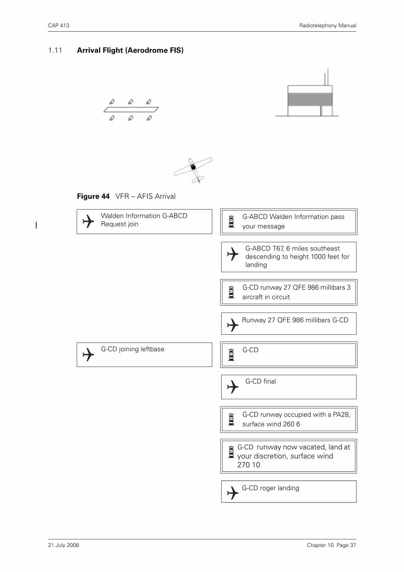
CAP 413 Radiotelephony Manual
1.11 Arrival Flight (Aerodrome FIS)
Figure 44 VFR – AFIS Arrival
Walden Information G-ABCDRequest join
G-ABCD Walden Information pass your message
G-ABCD T67, 6 miles southeast descending to height 1000 feet for landing
G-CD runway 27 QFE 986 millibars 3 aircraft in circuit
Runway 27 QFE 986 millibars G-CD
G-CD joining leftbase G-CD
G-CD final
G-CD runway occupied with a PA28, surface wind 260 6
G-CD runway now vacated, land at your discretion, surface wind270 10
G-CD roger landing
Chapter 10 Page 3721 July 2008
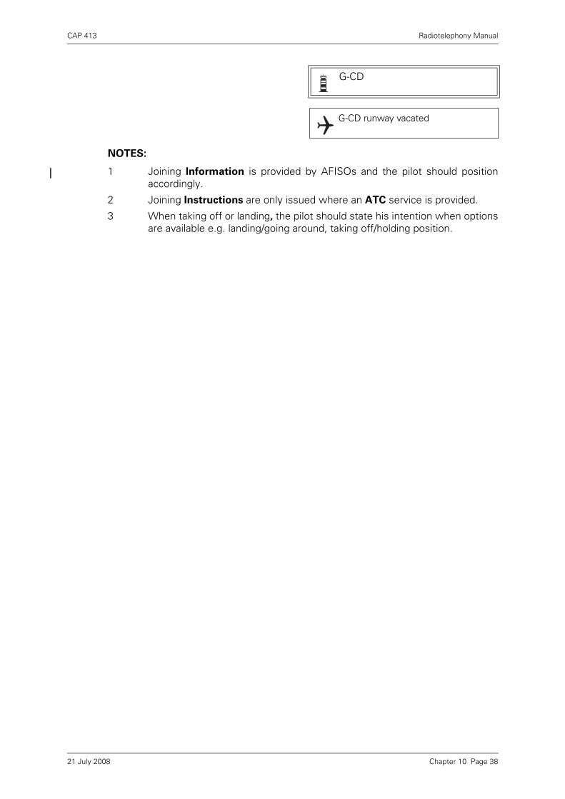
CAP 413 Radiotelephony Manual
NOTES:
1 Joining Information is provided by AFISOs and the pilot should positionaccordingly.
2 Joining Instructions are only issued where an ATC service is provided.
3 When taking off or landing, the pilot should state his intention when optionsare available e.g. landing/going around, taking off/holding position.
G-CD
G-CD runway vacated
Chapter 10 Page 3821 July 2008
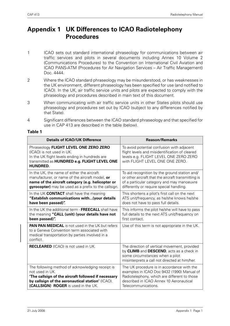
CAP 413 Radiotelephony Manual
Appendix 1 UK Differences to ICAO Radiotelephony
Procedures
1 ICAO sets out standard international phraseology for communications between airtraffic services and pilots in several documents including Annex 10 Volume 2(Communications Procedures) to the Convention on International Civil Aviation andICAO PANS-ATM (Procedures for Air Navigation Services – Air Traffic Management)Doc. 4444.
2 Where the ICAO standard phraseology may be misunderstood, or has weaknesses inthe UK environment, different phraseology has been specified for use (and notified toICAO). In the UK, air traffic service units and pilots are expected to comply with thephraseology and procedures described in main text of this document.
3 When communicating with air traffic service units in other States pilots should usephraseology and procedures set out by ICAO (subject to any differences notified bythat State).
4 Significant differences between the ICAO standard phraseology and that specified foruse in CAP 413 are described in the table (below).
Table 1
Details of ICAO/UK Difference Reason/Remarks
Phraseology FLIGHT LEVEL ONE ZERO ZERO (ICAO) is not used in UK. In the UK flight levels ending in hundreds are transmitted as HUNDRED e.g. FLIGHT LEVEL ONE
HUNDRED.
To avoid potential confusion with adjacent flight levels and misidentification of cleared levels e.g. FLIGHT LEVEL ONE ZERO ZERO with FLIGHT LEVEL ONE ONE ZERO.
In the UK, the name of either the aircraft manufacturer, or name of the aircraft model, or
name of the aircraft category (e.g. helicopter or
gyrocopter) may be used as a prefix to the callsign.
To aid recognition by the ground station and/or other aircraft that the aircraft transmitting is of a particular category and may manoeuvre differently or require special handling.
In the UK CONTACT shall have the meaning “Establish communications with...(your details
have been passed)”.
This shortens a pilot’s first call on the next ATS unit/frequency, as he/she knows he/she does not have to pass full details.
In the UK the additional term - FREECALL shall have the meaning “CALL (unit) (your details have not
been passed)”.
This informs the pilot he/she will have to pass full details to the next ATS unit/frequency on first contact.
PAN PAN MEDICAL is not used in the UK but refers to a Geneva Convention term associated with medical transportation by parties involved in a conflict.
Use of this term is not appropriate in the UK.
RECLEARED (ICAO) is not used in UK. The direction of vertical movement, provided by CLIMB and DESCEND, acts as a check in some circumstances when a pilot misinterprets a call not directed at him/her.
The following method of acknowledging receipt is not used in UK.‘The callsign of the aircraft followed if necessary
by callsign of the aeronautical station’ (ICAO).(CALLSIGN) ROGER is used in the UK.
The UK procedure is in accordance with the examples in ICAO Doc 9432 (1990) Manual of Radiotelephony, which are different to those described in ICAO Annex 10 Aeronautical Telecommunications.
Appendix 1 Page 121 July 2008
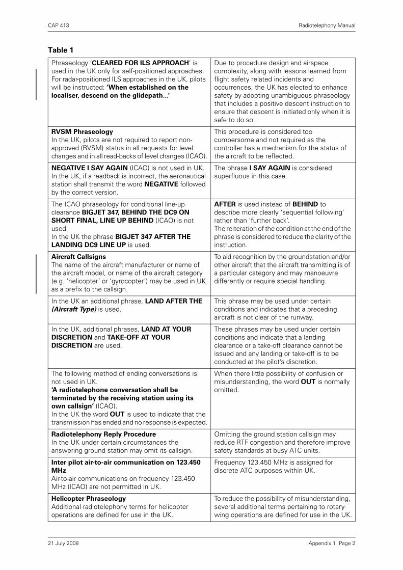
CAP 413 Radiotelephony Manual
Phraseology ‘CLEARED FOR ILS APPROACH’ is used in the UK only for self-positioned approaches. For radar-positioned ILS approaches in the UK, pilots will be instructed: ‘When established on the
localiser, descend on the glidepath...’
Due to procedure design and airspace complexity, along with lessons learned from flight safety related incidents and occurrences, the UK has elected to enhance safety by adopting unambiguous phraseology that includes a positive descent instruction to ensure that descent is initiated only when it is safe to do so.
RVSM Phraseology
In the UK, pilots are not required to report non-approved (RVSM) status in all requests for level changes and in all read-backs of level changes (ICAO).
This procedure is considered too cumbersome and not required as the controller has a mechanism for the status of the aircraft to be reflected.
NEGATIVE I SAY AGAIN (ICAO) is not used in UK.In the UK, if a readback is incorrect, the aeronautical station shall transmit the word NEGATIVE followed by the correct version.
The phrase I SAY AGAIN is considered superfluous in this case.
The ICAO phraseology for conditional line-up clearance BIGJET 347, BEHIND THE DC9 ON
SHORT FINAL, LINE UP BEHIND (ICAO) is not used.In the UK the phrase BIGJET 347 AFTER THE
LANDING DC9 LINE UP is used.
AFTER is used instead of BEHIND to describe more clearly ‘sequential following’ rather than ‘further back’. The reiteration of the condition at the end of the phrase is considered to reduce the clarity of the instruction.
Aircraft Callsigns
The name of the aircraft manufacturer or name of the aircraft model, or name of the aircraft category (e.g. ‘helicopter’ or ‘gyrocopter’) may be used in UK as a prefix to the callsign.
To aid recognition by the groundstation and/or other aircraft that the aircraft transmitting is of a particular category and may manoeuvre differently or require special handling.
In the UK an additional phrase, LAND AFTER THE
(Aircraft Type) is used. This phrase may be used under certain conditions and indicates that a preceding aircraft is not clear of the runway.
In the UK, additional phrases, LAND AT YOUR
DISCRETION and TAKE-OFF AT YOUR
DISCRETION are used.
These phrases may be used under certain conditions and indicate that a landing clearance or a take-off clearance cannot be issued and any landing or take-off is to be conducted at the pilot’s discretion.
The following method of ending conversations is not used in UK.‘A radiotelephone conversation shall be
terminated by the receiving station using its
own callsign’ (ICAO).In the UK the word OUT is used to indicate that the transmission has ended and no response is expected.
When there little possibility of confusion or misunderstanding, the word OUT is normally omitted.
Radiotelephony Reply Procedure
In the UK under certain circumstances the answering ground station may omit its callsign.
Omitting the ground station callsign may reduce RTF congestion and therefore improve safety standards at busy ATC units.
Inter pilot air-to-air communication on 123.450
MHz
Air-to-air communications on frequency 123.450 MHz (ICAO) are not permitted in UK.
Frequency 123.450 MHz is assigned for discrete ATC purposes within UK.
Helicopter Phraseology
Additional radiotelephony terms for helicopter operations are defined for use in the UK.
To reduce the possibility of misunderstanding, several additional terms pertaining to rotary-wing operations are defined for use in the UK.
Table 1
Appendix 1 Page 221 July 2008

CAP 413 Radiotelephony Manual
Listening Watch on 121.5 MHz
ICAO Requirements for Aeronautical Station Listening Watch on VHF emergency channel 121.5 MHz are not applied in UK.
VHF emergency channel frequency 121.5 MHz is not routinely monitored at civil aerodromes, however, it is monitored H24 at Area Control Centres with coverage over most of UK above 3000’ amsl.
Atmospheric Pressure
The term HECTOPASCAL is not used in the UK.When describing atmospheric pressure, the term MILLIBAR (Mb) is used in the UK in place of HECTOPASCAL (hPa) (One Millibar being equal to one Hectopascal).
Table 1
Appendix 1 Page 321 July 2008

INTENTIONALLY LEFT BLANK

CAP 413 Radiotelephony Manual
Bibliography Page 1
Bibliography
1
ICAO Annex 10 Volume 2 Communication Procedures
ICAO Document No. 4444 Procedures for Air Navigation Services - Air TrafficManagement (PANS-ATM)
ICAO Document No. 8400 Procedures for Air Navigation Services – ICAOAbbreviations and Codes (PANS-ABC)
ICAO Document No. 9432 Manual of Radiotelephony
CAP 32 UK Aeronautical Information Publication (AIP) (All ‘ENR’ references arecontained herein.)
CAP 493 Manual of Air Traffic Services (MATS Part 1)
CAP 410 Manual of Flight Information Services (Consists of two volumes, Part A andPart B)
CAP 452 Aeronautical Radio Station Operator’s Guide
CAP 774 UK Flight Information Services (effective 12 March 2009)
All CAA Publications are available from the CAA website at www.caa.co.uk/publications.
21 July 2008

INTENTIONALLY LEFT BLANK

CAP 413 Radiotelephony Manual
Index
Numerics
8.33 kHz Phraseology Chapter 9, Page 3
A
Abandon take-off Chapter 4, Page 8
Abbreviations Chapter 1, Page 4
ACAS/TCAS Phraseology Chapter 5, Page 6
Acknowledgement of Receipt Chapter 2, Page 11
Aerodrome Air/Ground Communication Service Chapter 2, Page 7
Aerodrome Control Service Chapter 1, Page 1
Aerodrome Flight Information Service (AFIS) Chapter 1, Page 1
Aerodrome Flight Information Service Officer (AFISO) Chapter 4, Page 15
Aerodrome Traffic Circuit Chapter 4, Page 8
Aerodrome Traffic Zone Chapter 1, Page 1Chapter 4, Page 15
Aeronautical stations Chapter 2, Page 7
Air traffic control service Chapter 2, Page 7
Air/Ground Station Identification Chapter 4, Page 27
Airborne Collision Avoidance System Chapter 1, Page 1
Aircraft Operating Agency Messages Chapter 9, Page 2
Aircraft radio faults Chapter 2, Page 17
AIRPROX Chapter 1, Page 1Chapter 1, Page 5Chapter 9, Page 1
Airway Chapter 1, Page 2
Altitude Chapter 1, Page 2
Approach Control Service Phraseology Chapter 6, Page 1
Approach control unit Chapter 6, Page 3Chapter 6, Page 6
Area Control Service Phraseology Chapter 7, Page 1
Area Navigation Global Navigation Satellite System RNAV (GNSS) Chapter 6, Page 17
ATC instructions Chapter 3, Page 4
ATC route clearance Chapter 2, Page 12Chapter 6, Page 2
Index Page 121 July 2008

CAP 413 Radiotelephony Manual
ATIS Chapter 1, Page 5Chapter 4, Page 1Chapter 4, Page 4Chapter 4, Page 9Chapter 4, Page 40Chapter 6, Page 6
ATZ Chapter 1, Page 5Chapter 4, Page 1Chapter 4, Page 15Chapter 4, Page 27
Avoiding Action Phraseology Chapter 5, Page 5
C
Callsign Prefix - STUDENT Chapter 10, Page 32
Callsigns for Aeronautical Stations Chapter 2, Page 7
Callsigns for Aircraft Chapter 2, Page 8
Cancel an IFR flight plan Chapter 3, Page 8
Categories of Message Chapter 2, Page 18
Clearance Issue Chapter 2, Page 11
Clearance limit Chapter 4, Page 2
Communication failure Chapter 2, Page 15
Communications and Loss of Communications Chapter 5, Page 7
Conditional clearances Chapter 4, Page 6
Continuation of Communications Chapter 2, Page 9
Continuous listening watch Chapter 4, Page 24
Controlled airspace Chapter 1, Page 2Chapter 6, Page 3Chapter 7, Page 2
Corrections and Repetitions Chapter 2, Page 10
CPDLC Chapter 1, Page 5
Cross a Runway Chapter 4, Page 25
D
D&D Sections Chapter 8, Page 1
DAAIS Chapter 1, Page 6Chapter 5, Page 9
DACS Chapter 1, Page 6
Danger Area Activity Information Service (DAAIS) Chapter 5, Page 7Chapter 5, Page 9
Danger Area Crossing Service (DACS) Chapter 5, Page 7Chapter 10, Page 29
Definitions Chapter 1, Page 1
Index Page 221 July 2008

CAP 413 Radiotelephony Manual
Departure Information and Engine Starting Procedures Chapter 4, Page 1
Descent clearance Chapter 6, Page 3
Designated Positions in the Traffic Circuit Chapter 4, Page 8
Direction Finding (DF) Chapter 6, Page 11
Distress and Urgency Communication Procedures Chapter 8, Page 1
E
Emergency Message Chapter 8, Page 3
Emergency Service Chapter 8, Page 1
Essential Aerodrome Information Chapter 4, Page 14
F
Final Approach and Landing Chapter 4, Page 11
Flight Information Service (FIS) Chapter 2, Page 7Chapter 10, Page 34
Flight Plans Chapter 3, Page 7
Flight Receiving Avoiding Action Chapter 10, Page 33
Flight Receiving Lower Airspace Radar Service Chapter 10, Page 21
Flights Crossing Airways Chapter 7, Page 3
Flights Holding En-Route Chapter 7, Page 3
Flights Joining Airways Chapter 7, Page 2
Flights Leaving Airways Chapter 7, Page 2
G
Glidepath Chapter 6, Page 8
Go Around Chapter 4, Page 13
H
Helicopter Callsigns Chapter 4, Page 19
Helicopter Phraseology Chapter 4, Page 20
Hold en-route Chapter 7, Page 3
Holding pattern Chapter 6, Page 16
Holding point Chapter 1, Page 3Chapter 4, Page 2Chapter 4, Page 5
Hours of Service and Communications Watch Chapter 2, Page 17
I
IFR Arrivals Chapter 6, Page 3
IFR Departures Chapter 6, Page 1
Index Page 321 July 2008

CAP 413 Radiotelephony Manual
ILS Chapter 1, Page 7Chapter 6, Page 8
Imposition of Silence Chapter 8, Page 5
Initial Call – IFR Chapter 3, Page 4
Initial Call – VFR Chapter 3, Page 5
Instrument approach procedures Chapter 6, Page 15
Instrument Departures Chapter 6, Page 1
Interceptions by Military Aircraft Chapter 9, Page 2
L
Landing Altimeter Setting (QNE) Chapter 6, Page 21
Letters Chapter 2, Page 2
Level Instructions Chapter 3, Page 1
Listening watch Chapter 2, Page 17
Localiser Chapter 6, Page 8
Lower Airspace Radar Service (LARS) Chapter 6, Page 26Chapter 10, Page 29
M
MATZ Chapter 1, Page 7Chapter 6, Page 26
MATZ Penetration Service Chapter 6, Page 26Chapter 10, Page 21
MAYDAY Chapter 8, Page 1Chapter 8, Page 3
Meteorological aerodrome reports Chapter 4, Page 37
Meteorological Conditions Chapter 4, Page 37
Microwave Chapter 6, Page 8
Microwave Approach Chapter 1, Page 3
Military Safety Broadcast - Securité Chapter 10, Page 31
Military Visual Circuit Chapter 10, Page 25
Millibars Chapter 3, Page 2
Missed Approach Chapter 4, Page 13
Missed Approach Procedure Chapter 1, Page 3
MLS Chapter 1, Page 7Chapter 6, Page 8
Movement Instructions Chapter 4, Page 24
Movement of vehicles Chapter 4, Page 24
Index Page 421 July 2008

CAP 413 Radiotelephony Manual
N
NDB(L) and VOR Procedures Chapter 6, Page 15
Numbers Chapter 2, Page 3
O
Offshore Communication Service Chapter 4, Page 30
Offshore Phraseology Chapter 4, Page 31
Offshore Station Identification Chapter 4, Page 31
Oil Pollution Reporting Chapter 9, Page 2
Operations by Aircraft Deploying Brake Chutes Chapter 9, Page 4
P
PAN PAN Chapter 8, Page 1Chapter 8, Page 3
PAR Approach Chapter 6, Page 21
Position Reporting Chapter 3, Page 7Chapter 7, Page 1
Practice Pan Chapter 10, Page 35
Pre-Departure Manoeuvring Chapter 4, Page 4
Pushback and Powerback Chapter 4, Page 2
Q
QDM Chapter 1, Page 7Chapter 6, Page 11
QDR Chapter 1, Page 7Chapter 6, Page 11
QFE Chapter 1, Page 8Chapter 4, Page 31Chapter 6, Page 21Chapter 10, Page 24
QNE Chapter 1, Page 8Chapter 6, Page 21
QNH Chapter 1, Page 8Chapter 3, Page 1Chapter 4, Page 1Chapter 4, Page 4Chapter 6, Page 19
QTE Chapter 1, Page 8Chapter 6, Page 11
R
Radar Identification Chapter 1, Page 3
Radar Identification of Aircraft Chapter 5, Page 1
Index Page 521 July 2008

CAP 413 Radiotelephony Manual
Radar service Chapter 5, Page 1Chapter 5, Page 4
Radar Vectoring Chapter 1, Page 3Chapter 5, Page 4
Radio Procedures – Practice Emergencies Chapter 8, Page 4
Read Back Requirements Chapter 2, Page 11
Readability Scale Chapter 2, Page 16
Reduced Vertical Separation Minimum Chapter 7, Page 4
Relayed Emergency Message Chapter 8, Page 5
Runway Surface Conditions Chapter 4, Page 38
Runway Vacating and Communicating After Landing Chapter 4, Page 13
Runway Visual Range Chapter 1, Page 4
Runway Visual Range (RVR)/Visibility/Absolute Minimum Chapter 4, Page 38
RVR Chapter 1, Page 8Chapter 4, Page 38
RVSM Chapter 7, Page 4
S
SAFETYCOM Chapter 1, Page 4Chapter 4, Page 34
Safetycom Chapter 4, Page 34
Secondary Surveillance Radar Phraseoloy Chapter 5, Page 2
Securité Chapter 10, Page 31
Simultaneous Transmissions Chapter 2, Page 14
Special Purpose Codes Chapter 8, Page 2
Special VFR Chapter 1, Page 4Chapter 6, Page 2Chapter 6, Page 7
Special VFR clearances Chapter 6, Page 7
Speechless Code Chapter 8, Page 4
SRA Chapter 1, Page 8Chapter 6, Page 18Chapter 6, Page 19
SSR Chapter 1, Page 8
Standard Overhead Join Chapter 4, Page 34Chapter 4, Page 36
Standard Words and Phrases Chapter 2, Page 5
States of Emergency Chapter 8, Page 1
Straight-in approach Chapter 4, Page 10
STUDENT Chapter 10, Page 32
Surveillance Radar Approach (SRA) Chapter 6, Page 18
Index Page 621 July 2008
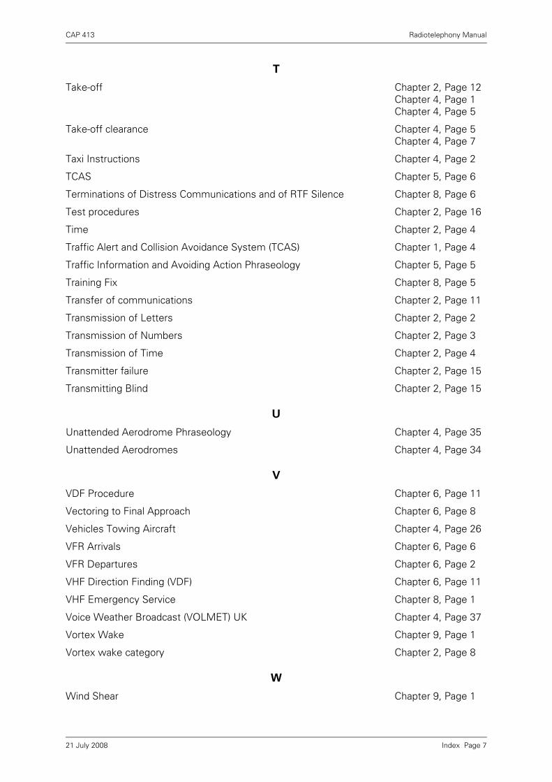
CAP 413 Radiotelephony Manual
T
Take-off Chapter 2, Page 12Chapter 4, Page 1Chapter 4, Page 5
Take-off clearance Chapter 4, Page 5Chapter 4, Page 7
Taxi Instructions Chapter 4, Page 2
TCAS Chapter 5, Page 6
Terminations of Distress Communications and of RTF Silence Chapter 8, Page 6
Test procedures Chapter 2, Page 16
Time Chapter 2, Page 4
Traffic Alert and Collision Avoidance System (TCAS) Chapter 1, Page 4
Traffic Information and Avoiding Action Phraseology Chapter 5, Page 5
Training Fix Chapter 8, Page 5
Transfer of communications Chapter 2, Page 11
Transmission of Letters Chapter 2, Page 2
Transmission of Numbers Chapter 2, Page 3
Transmission of Time Chapter 2, Page 4
Transmitter failure Chapter 2, Page 15
Transmitting Blind Chapter 2, Page 15
U
Unattended Aerodrome Phraseology Chapter 4, Page 35
Unattended Aerodromes Chapter 4, Page 34
V
VDF Procedure Chapter 6, Page 11
Vectoring to Final Approach Chapter 6, Page 8
Vehicles Towing Aircraft Chapter 4, Page 26
VFR Arrivals Chapter 6, Page 6
VFR Departures Chapter 6, Page 2
VHF Direction Finding (VDF) Chapter 6, Page 11
VHF Emergency Service Chapter 8, Page 1
Voice Weather Broadcast (VOLMET) UK Chapter 4, Page 37
Vortex Wake Chapter 9, Page 1
Vortex wake category Chapter 2, Page 8
W
Wind Shear Chapter 9, Page 1
Index Page 721 July 2008

INTENTIONALLY LEFT BLANK