Canopy Rear Door Replacement Instructions ( WIND 0004) Rear Door.pdf · Canopy Rear Door...
6
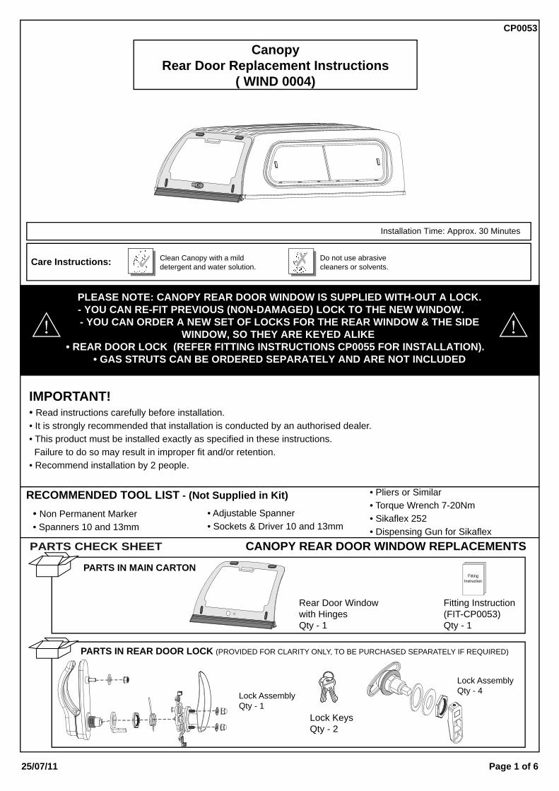
IMPORTANT! • Read instructions carefully before installation. • It is strongly recommended that installation is conducted by an authorised dealer. • This product must be installed exactly as specified in these instructions. Failure to do so may result in improper fit and/or retention. • Recommend installation by 2 people. RECOMMENDED TOOL LIST - (Not Supplied in Kit) • Non Permanent Marker • Spanners 10 and 13mm • Adjustable Spanner • Sockets & Driver 10 and 13mm • Pliers or Similar • Torque Wrench 7-20Nm • Sikaflex 252 • Dispensing Gun for Sikaflex PARTS CHECK SHEET CANOPY REAR DOOR WINDOW REPLACEMENTS PARTS IN MAIN CARTON Rear Door Window with Hinges Qty - 1 PARTS IN REAR DOOR LOCK (PROVIDED FOR CLARITY ONLY, TO BE PURCHASED SEPARATELY IF REQUIRED) Lock Assembly Qty - 1 Lock Assembly Qty - 4 Lock Keys Qty - 2 PLEASE NOTE: CANOPY REAR DOOR WINDOW IS SUPPLIED WITH-OUT A LOCK. - YOU CAN RE-FIT PREVIOUS (NON-DAMAGED) LOCK TO THE NEW WINDOW. - YOU CAN ORDER A NEW SET OF LOCKS FOR THE REAR WINDOW & THE SIDE WINDOW, SO THEY ARE KEYED ALIKE • REAR DOOR LOCK (REFER FITTING INSTRUCTIONS CP0055 FOR INSTALLATION). • GAS STRUTS CAN BE ORDERED SEPARATELY AND ARE NOT INCLUDED Clean Canopy with a mild detergent and water solution. Do not use abrasive cleaners or solvents. Care Instructions: CP0053 Page 1 of 6 25/07/11 Installation Time: Approx. 30 Minutes Canopy Rear Door Replacement Instructions ( WIND 0004) Fitting Instruction (FIT-CP0053) Qty - 1 Fitting Instruction
Transcript of Canopy Rear Door Replacement Instructions ( WIND 0004) Rear Door.pdf · Canopy Rear Door...
IMPORTANT!• Read instructions carefully before installation.• It is strongly recommended that installation is conducted by an authorised dealer.• This product must be installed exactly as specified in these instructions. Failure to do so may result in improper fit and/or retention.• Recommend installation by 2 people.
RECOMMENDED TOOL LIST - (Not Supplied in Kit)
• Non Permanent Marker• Spanners 10 and 13mm
• Adjustable Spanner• Sockets & Driver 10 and 13mm
• Pliers or Similar• Torque Wrench 7-20Nm• Sikaflex 252• Dispensing Gun for Sikaflex
PARTS CHECK SHEET CANOPY REAR DOOR WINDOW REPLACEMENTS
PARTS IN MAIN CARTON
Rear Door Windowwith HingesQty - 1
PARTS IN REAR DOOR LOCK (PROVIDED FOR CLARITY ONLY, TO BE PURCHASED SEPARATELY IF REQUIRED)
Lock AssemblyQty - 1
Lock AssemblyQty - 4
Lock KeysQty - 2
PLEASE NOTE: CANOPY REAR DOOR WINDOW IS SUPPLIED WITH-OUT A LOCK.- YOU CAN RE-FIT PREVIOUS (NON-DAMAGED) LOCK TO THE NEW WINDOW. - YOU CAN ORDER A NEW SET OF LOCKS FOR THE REAR WINDOW & THE SIDE
WINDOW, SO THEY ARE KEYED ALIKE • REAR DOOR LOCK (REFER FITTING INSTRUCTIONS CP0055 FOR INSTALLATION).
• GAS STRUTS CAN BE ORDERED SEPARATELY AND ARE NOT INCLUDED
Clean Canopy with a milddetergent and water solution.
Do not use abrasivecleaners or solvents.Care Instructions:
CP0053
Page 1 of 625/07/11
Installation Time: Approx. 30 Minutes
CanopyRear Door Replacement Instructions
( WIND 0004)
Fitting Instruction(FIT-CP0053)Qty - 1
FittingInstruction

1.
2.
3.
Diagram: 3 - DISCONNECT GAS STRUTS
Diagram: 2 - MARK HINGE LOCATIONS ON CANOPY
Diagram: 1 - CLEAN & CLEAR WORK AREA
Ensure that any broken glass is removedfrom the window frame & canopy interior.Ensure work area has been made safe.(ref. diagram1).CAUTION: Use caution when workingnear broken edges.Use a vacuum cleaner to removebroken glass.
Carefully open the rear door.Using a non permanent marker, markthe position of the two (2) hinges on thecanopy as shown to assist with positioningthe replacement door. (ref. diagram2).
Detach gas struts from the canopy reardoor by inserting a small flat bladescrewdriver and adjusting the spring clipon the strut as shown. (ref. diagram3).
DO NOT CLEANGLASS WINDOW PANELS
OPENREAR DOOR1
1DETACHGAS STRUT FROM
CANOPY REAR DOOR
MARKHINGE POSITION
2
TO REMOVE:
CP0053
Page 2 of 625/07/11

REMOVE BOLT
NOTE ORIENTATIONOF THE SPRING
1
NOTE ORIENTATIONOF THE SPRING
3
REMOVE LEVERASSEMBLY
REMOVESPRING
REMOVE LOCK NUT
REMOVE SPRING RETAINER
REMOVE NUTS& WASHERS
4.
5.
6.
Diagram: 6 - DISASSEMBLE (IF NEW LOCK WAS ORDERED)
Diagram: 5 - (OPTIONAL) REMOVAL OF (NON-DAMAGED) LOCKS
Diagram: 4 - UNDO HINGE NUTS AND REMOVE REAR DOOR
Two (2) people are required for this step.One person will need to support the weightof the door and carefully remove it whenthe hardware has been removed.The other person will need to be inside thecanopy to remove the four (4) nuts andwashers securing the hinges to the canopyas shown. Remove old Sikaflex sealant on the outsideof the canopy beneath the hinges. Clean with wax and grease remover and dry.IMPORTANT: Take care when removingthe nuts and washers, by supporting andremoving the metal plate, as the nuts arethe only items holding the plate in place.If metal plate is not supported it couldfall and cause damage to the vehicle oryourself. (ref. diagram4).
Remove plastic cover by removing two (2)phillips head screws.Disconnect the pullrods as shown.Note the orientation of the spring.Using a 10mm socket or spanner remove the interior handle and the bolt securing the lever assembly to the lock.Remove the lever assembly and spring.Remove the lock nut and spring retainer.Remove the nut securing the handle to thedoor. Remove the handle assembly fromthe door as shown.(ref. diagram5).
If new lock was ordered, note the orientation of the spring.Using a 10mm ring spanner or socket remove the interior handle and the bolt securing the lever assembly to the lock.Remove the lever assembly and spring.Remove the lock nut and spring retainer.Remove the nut and washers from thethread on the handle as shown.Remove and retain the plastic cover andhardware from the new door.(ref. diagram6).
VIEW FROM INSIDE THE CANOPY LOOKING REARWARD
REMOVEHINGE NUTS,
WASHERS ANDMETAL PLATE
2
SUPPORTMETAL PLATE
REMOVEREAR DOOR3
REMOVE INTERIORLOCK COVER
UNCLIP PULLRODSFROM RETAINER CLIPS2
1
13mm
10mm
1
7 2
REMOVE BOLT4
3
REMOVE LEVER ASSEMBLY5
4
REMOVE SPRING6
56
REMOVE LOCK NUTREMOVE SPRING RETAINERREMOVE NUTS & WASHERS9
REMOVEHANDLE ASSEMBLY
10
78
CP0053
Page 3 of 625/07/11

7.
8.
9.
Diagram: 9 - APPLY SIKAFLEX TO HINGE STUDS
Diagram: 8 - FIT SPRING & LEVER ASSEMBLY
Diagram: 7 - ORIENT AND FIT LOCK TO WINDOW
Fit the handle to the new door and securewith removed nut and washers.Fit spring retainer and secure with lock nut.Re-fit the spring in the orientationpreviously noted. (ref. diagram7).
Fit the lever assembly and secure withbolt and washer as shown.Using a 10mm ring spanner tighten the boltto secure the lever assembly to the lock.Using pliers or similar you will need to bringthe long leg of the spring around to the frontof the cam as shown.Connect the pullrods, Do Not replace thecover at this stage. (ref. diagram8).
Apply Sikaflex bead in 5mm diameter aroundeach of the four (4) studs on the top of hingegasket, onto the gasket surface that willcontact the canopy. (ref. diagram9).
CLIP PULLRODSINTO RETAINER CLIPS4
FIT HANDLE1
FIT LEVER ASSEMBLY
CAM
SPRING IN ITSRELAXED STATE
APPLY SIKAFLEXAROUND STUDS
RUBBER GASKET
1
TIGHTENBOLT TO 7Nm
FIT SPRING TOFRONT OF CAM
FIT NUTS & WASHERSDO UP TO 5Nm
2
FIT SPRING RETAINER3
FIT LOCK NUT DO UP TO 7Nm
POSITION SPRING RETAINER
4
5
2
3
CP0053
Page 4 of 625/07/11
1
NOT SUPPLIED

11.
Diagram: 11 - CONNECT GAS STRUTS
Attach gas struts. Narrow end should beattached to the rear door strut bracket.Attach wide end to the strut bracket on thecanopy clamp frame as shown.Repeat for the other side of the rear door.(ref. diagram11).It is important gas struts are orientatedcorrectly.
ATTACHGAS STRUTTO CANOPY
CLAMP FRAME
2 MOUNT WIDE END OF GAS STRUTTO CANOPY CLAMP FRAME
1 ENSURE NARROW ENDOF GAS STRUT ISMOUNTED TO THE
REAR DOOR
CP0053
Page 5 of 625/07/11
CONTINUE TO NEXT PAGE
10.
Diagram: 10 - FIT REAR DOOR AND SECURE HINGES
Two (2) people are required for this step.One person will need to support the weightof the door and carefully align the hingeswith lines previously marked on the canopy.The other person will need to be inside thecanopy to re-fit the metal plate and securethe four (4) nuts and washers to the threadson the hinges as shown and tighten to 17Nm.(ref. diagram10).
VIEW FROM INSIDE THE CANOPY LOOKING REARWARD
RE-INSTALLHINGE NUTS,WASHERS &
METAL PLATEDO UP TO 17Nm
3
FITREAR DOOR
1
ALIGN HINGES TO MARKED LINES2
13mm
12.
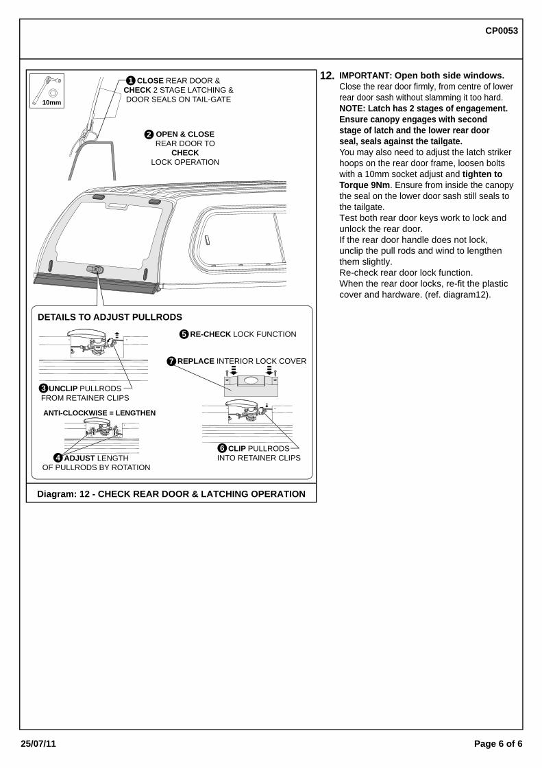
Diagram: 12 - CHECK REAR DOOR & LATCHING OPERATION
IMPORTANT: Open both side windows.Close the rear door firmly, from centre of lowerrear door sash without slamming it too hard.NOTE: Latch has 2 stages of engagement.Ensure canopy engages with secondstage of latch and the lower rear doorseal, seals against the tailgate.You may also need to adjust the latch strikerhoops on the rear door frame, loosen boltswith a 10mm socket adjust and tighten toTorque 9Nm. Ensure from inside the canopythe seal on the lower door sash still seals tothe tailgate.Test both rear door keys work to lock andunlock the rear door.If the rear door handle does not lock,unclip the pull rods and wind to lengthenthem slightly.Re-check rear door lock function.When the rear door locks, re-fit the plasticcover and hardware. (ref. diagram12).
OPEN & CLOSEREAR DOOR TO
CHECKLOCK OPERATION
DETAILS TO ADJUST PULLRODS
ADJUST LENGTHOF PULLRODS BY ROTATION
ANTI-CLOCKWISE = LENGTHEN
4
UNCLIP PULLRODSFROM RETAINER CLIPS
REPLACE INTERIOR LOCK COVER
RE-CHECK LOCK FUNCTION5
CLIP PULLRODSINTO RETAINER CLIPS6
3
7
CLOSE REAR DOOR &CHECK 2 STAGE LATCHING &DOOR SEALS ON TAIL-GATE10mm
1
2
CP0053
Page 6 of 625/07/11