CANopen
38
Industrial Automation - Customer View - Services - Training PhW - CANopen_soft_setup_en 10/ 2003 Slide 1/38 CANopen CANopen Software setup with PL7 and Sycon V2.8
-
Upload
stacy-vasquez -
Category
Documents
-
view
48 -
download
0
description
CANopen. Software setup with PL7 and Sycon V2.8. CANopen: Software setup - 2. Software setup. Click the individual stages for a detailed description. Declare the master card in the PLC. Configure processor/master card operation. Configure the master and nodes with the Sycon tool. - PowerPoint PPT Presentation
Transcript of CANopen

Industrial Automation - Customer View - Services - TrainingPhW - CANopen_soft_setup_en 10/ 2003
Slide 1/38
CANopenCANopen
Software setup
with PL7 and Sycon V2.8

Industrial Automation - Customer View - Services - TrainingPhW - CANopen_soft_setup_en 10/ 2003
Slide 2/38
Software setupSoftware setup
CANopen: Software setup - 2
Declare the master card in the PLC
Configure the master andnodes with the Sycon tool
Load the configuration via the Sycon tool
Select the configuration file in PL7 and save it
Transfer the application to the PLC
Verify implicit exchanges
Sycon mode
PL7 mode
Configureprocessor/master card operation
Click the individual stages
for a detailed description

Industrial Automation - Customer View - Services - TrainingPhW - CANopen_soft_setup_en 10/ 2003
Slide 3/38
Declaring the master card in the PLCDeclaring the master card in the PLC
CANopen: Software setup - 3
The CANopen PCMCIA master card is inserted in the designated slotfor communication modules in theprocessor module.
The CANopen master card iscompatible with all processormodules >= V5.0 except TSX57103
Screencam 1 Back

Industrial Automation - Customer View - Services - TrainingPhW - CANopen_soft_setup_en 10/ 2003
Slide 4/38
Configuring processor/master card operationConfiguring processor/master card operation
CANopen: Software setup - 4
Synchronise updating of memory
zones associated with the I/O
Define %MW memory zone to which the inputs are copied
Define fallback mode for outputs and for %MW memory zone where outputs are
read
Launch Sycon configuration
software
Select Sycon configuration file and choose loading mode
Behaviour of bus on start-up*
Activate watchdog
1
2
3
4
5
Screencam 2 Back* If “Semi-automatic” or “By program” is selected here, bus start-upis controlled by the command word %QWy.1.0 (y = processor slot number).

Industrial Automation - Customer View - Services - TrainingPhW - CANopen_soft_setup_en 10/ 2003
Slide 5/38
Configuring the master and nodes with the Sycon toolConfiguring the master and nodes with the Sycon toolConfiguring the master and nodes with the Sycon toolConfiguring the master and nodes with the Sycon tool
CANopen: Software setup - 5
Example with Addr1 = ATV58Addr 2 = BECKHOFF module
Example with ATV58.Direct use of predefined PDOs with modification of parameter settings
Example with BECKHOFF module.Modifying the mapping of predefined PDOs.
Select the network and insert the master
Declare the nodes
Set the bus parameters
Set node parameters with predefined PDOs
Set the operating parameters for the Sycon software
Set modular I/O node parameters
View global configuration and save
Import the EDS file for a new productExample of importing a BECKHOFF CANopen communication module

Industrial Automation - Customer View - Services - TrainingPhW - CANopen_soft_setup_en 10/ 2003
Slide 6/38
Selecting the network and inserting the CANopen masterSelecting the network and inserting the CANopen masterSelecting the network and inserting the CANopen masterSelecting the network and inserting the CANopen master
Screencam 3 Back
CANopen: Software setup - 6
File - New1 Select CANopen - OK2
Insert - Master3 Add TSX CPP 100 - OK4

Industrial Automation - Customer View - Services - TrainingPhW - CANopen_soft_setup_en 10/ 2003
Slide 7/38
Setting the operating mode parameters for the Sycon softwareSetting the operating mode parameters for the Sycon softwareSetting the operating mode parameters for the Sycon softwareSetting the operating mode parameters for the Sycon software
CANopen: Software setup - 7
Settings - Global Settings1 Activate Process Data Auto Addressing if required
Activate Automatic COB-ID Allocation if required
OK
2
If Process Data Auto Addressing is activated, Syconautomatically calculates the process data offset.Data is organised according to the sequence of PDOs and nodes.
Manual COB-ID allocation is used for PDO numbers >= 5 or for exchanging datadirectly from node to node: PDO linking.
Back

Industrial Automation - Customer View - Services - TrainingPhW - CANopen_soft_setup_en 10/ 2003
Slide 8/38
Setting the bus parametersSetting the bus parametersSetting the bus parametersSetting the bus parameters
Back
Select address of master2
Select SYNC object COB-ID Default value = 128
Communication profile DS301
+ select comm. cycle period
3
4
CANopen: Software setup - 8
Screencam 4
5
Settings - Bus parameter1Select transmission rate
Behaviour of master module in the event of a Node Guard or Heartbeat error:
Disabled:Does not affect the other stations.
Enabled: The master stops communication with all other stations.
6 Activate Heartbeat function(supported by TSXCPP110 card)
Enable automatic switch to operating mode (PDOs activated) if required.
7
Not in use

Industrial Automation - Customer View - Services - TrainingPhW - CANopen_soft_setup_en 10/ 2003
Slide 9/38
Importing a new EDS fileImporting a new EDS fileImporting a new EDS fileImporting a new EDS fileCANopen: Software setup - 9
File - Copy EDS1
Select the directory in which the new EDS file is located
together with the 3 associated .dib images
2
Click Open to import the files
3
BackScreencam 5a

Industrial Automation - Customer View - Services - TrainingPhW - CANopen_soft_setup_en 10/ 2003
Slide 10/38
Declaring the nodesDeclaring the nodesDeclaring the nodesDeclaring the nodes
Back
CANopen: Software setup - 10
Screencam 5
3
Insert - Node1
Add English ATV58 version at address 2
2
Add BK5120at address 3
Industrial Automation - Customer View - Services - TrainingPhW - CANopen_soft_setup_en 10/ 2003
Slide 11/38
Node configuration windowNode configuration windowNode configuration windowNode configuration window
CANopen: Software setup - 11
The values for Device Profile and Device
Type must be consistent with the values contained in object 1000H Device
Type
Automatic COB-ID allocation activated by
default
List of predefined PDOs
Access to Node Guarding and Heartbeat functions
Deactivate if you wish to retain process data when
the station is not connected
Access to boot-up sequence for each
node
Access to supported objects and to
parameters written during boot-up
sequence
Access to transmission parameters for each
PDO
Access to mapping for each PDO
Define new receive PDO
Define new transmit PDO
To activate predefined PDOs
Double click the relevant node to open the window
Industrial Automation - Customer View - Services - TrainingPhW - CANopen_soft_setup_en 10/ 2003
Slide 12/38
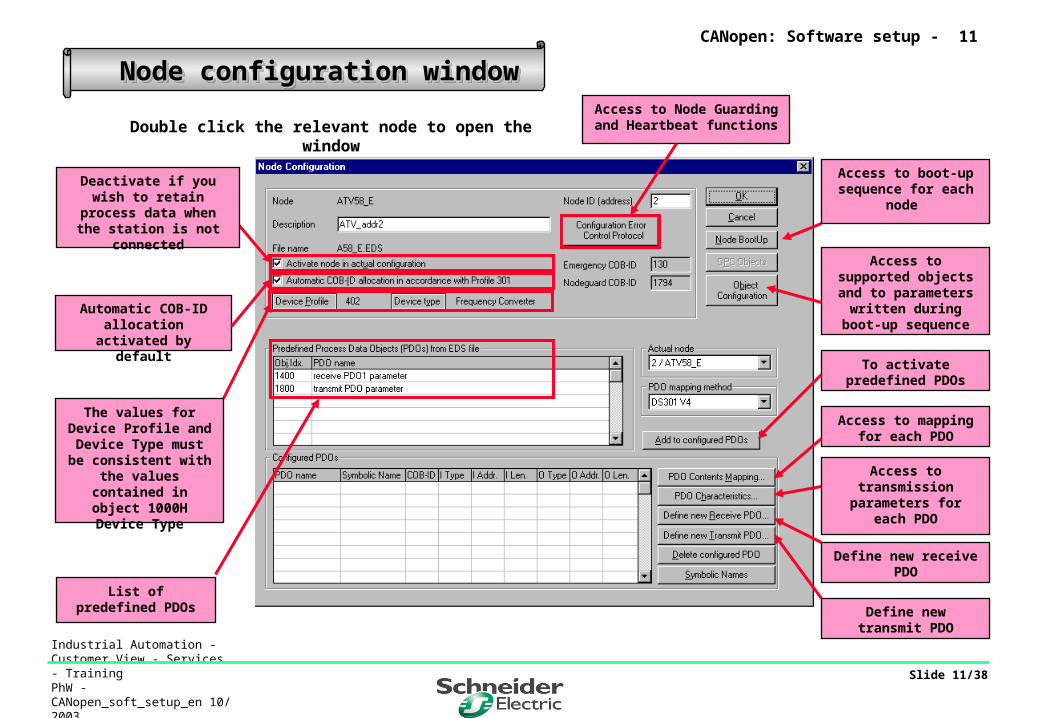
CANopen: Software setup - 12
Select monitoring mode: Node Guarding or Heartbeat
Polling time for master
Define monitoring time on node side:
Guard time x Life time factor
Time for which node is monitored by master
Time for which heartbeat is transmitted by node
List of values assigned to the Heartbeat parameters by the
various nodes
Node configuration with predefined PDOsNode configuration with predefined PDOsNode configuration with predefined PDOsNode configuration with predefined PDOs
Click “Configuration Error Control Protocol”
to access the Node Guarding or Heartbeat
settings
1
2
3
3’
Industrial Automation - Customer View - Services - TrainingPhW - CANopen_soft_setup_en 10/ 2003
Slide 13/38
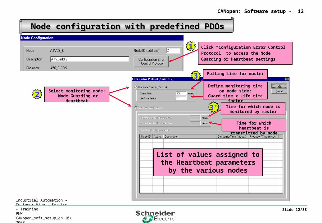
Node configuration with predefined receive PDOsNode configuration with predefined receive PDOsNode configuration with predefined receive PDOsNode configuration with predefined receive PDOs
Click the predefined PDO you wish to activate1
CANopen: Software setup - 13
Select the PDO receive mode (node side)
3
Click Add to configured PDOs2
3
Confirm5
Select the PDO triggering mode
(master side)
4
Industrial Automation - Customer View - Services - TrainingPhW - CANopen_soft_setup_en 10/ 2003
Slide 14/38
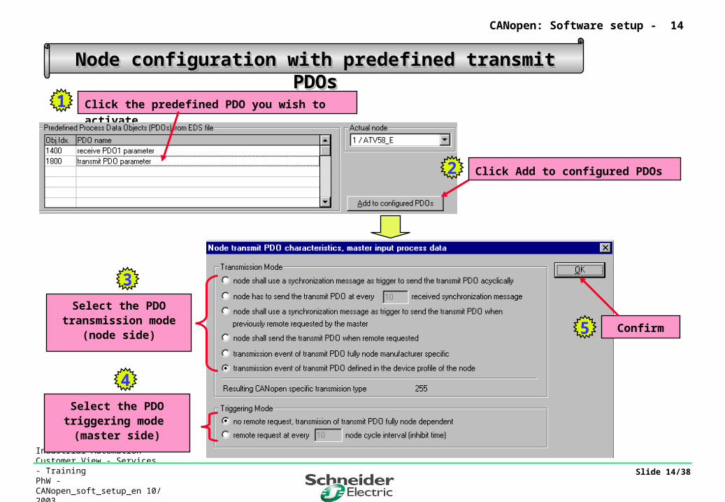
Node configuration with predefined transmit PDOsNode configuration with predefined transmit PDOsNode configuration with predefined transmit PDOsNode configuration with predefined transmit PDOs
Click the predefined PDO you wish to activate1
CANopen: Software setup - 14
Select the PDO transmission mode
(node side)
3
Confirm5
Click Add to configured PDOs2
Select the PDO triggering mode
(master side)
4

Industrial Automation - Customer View - Services - TrainingPhW - CANopen_soft_setup_en 10/ 2003
Slide 15/38
Sample view of process memory structureSample view of process memory structureSample view of process memory structureSample view of process memory structure
Receive PDOs correspond to
output variables
CANopen: Software setup - 15
Transmit PDOs correspond to
input variables
Address expressed
in number of words
Length expressed in
number of bytes
Industrial Automation - Customer View - Services - TrainingPhW - CANopen_soft_setup_en 10/ 2003
Slide 16/38
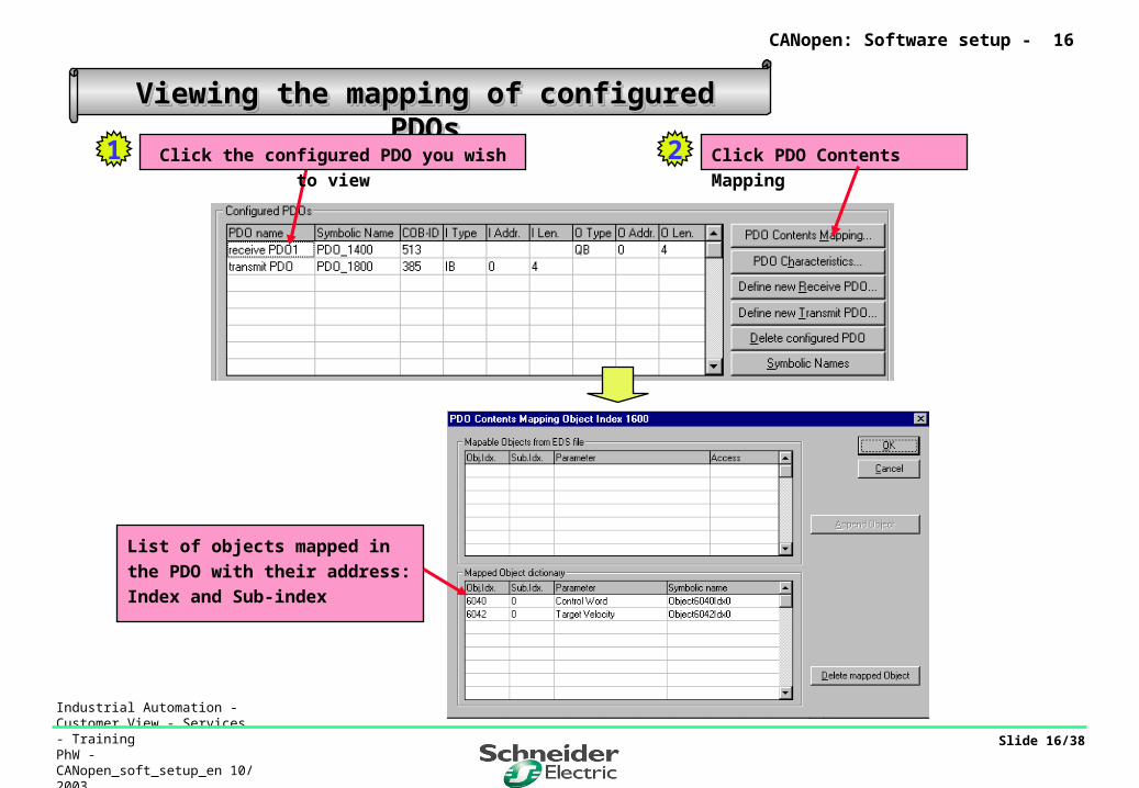
Viewing the mapping of configured PDOsViewing the mapping of configured PDOsViewing the mapping of configured PDOsViewing the mapping of configured PDOs
1
CANopen: Software setup - 16
Click PDO Contents Mapping2Click the configured PDO you wish to view
List of objects mapped in the PDO
with their address:
Index and Sub-index
Industrial Automation - Customer View - Services - TrainingPhW - CANopen_soft_setup_en 10/ 2003
Slide 17/38
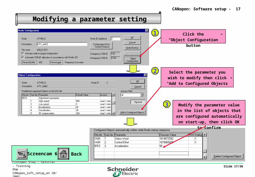
Modifying a parameter settingModifying a parameter settingModifying a parameter settingModifying a parameter setting
CANopen: Software setup - 17
Screencam 6 Back
1 Click the
“Object Configuration” button
2 Select the parameter you wish to
modify then click
“Add to Configured Objects”
3 Modify the parameter value in the
list of objects that are configured
automatically on start-up, then click
OK to confirm

Industrial Automation - Customer View - Services - TrainingPhW - CANopen_soft_setup_en 10/ 2003
Slide 18/38
CANopen: Software setup - 18
Node configuration for modular I/ONode configuration for modular I/ONode configuration for modular I/ONode configuration for modular I/O
Select monitoring mode : Node Guarding or Heartbeat
Polling time for master
Define monitoring time on node side:
Guard time x Life time factor
Time for which node is monitored by master
Period for which heartbeat is transmitted by node
List of values assigned to the Heartbeat parameters for the
various nodes
Click “Configuration Error Control Protocol”
to access the Node Guarding or Heartbeat
settings
1
2
3
3’

Industrial Automation - Customer View - Services - TrainingPhW - CANopen_soft_setup_en 10/ 2003
Slide 19/38
CANopen: Software setup - 19
Click Device Profile1
Node configuration for modular I/ONode configuration for modular I/ONode configuration for modular I/ONode configuration for modular I/O
Select profile 401
(Inputs/Outputs)2
Click Device Type
3
Select the I/O types that are
supported4

Industrial Automation - Customer View - Services - TrainingPhW - CANopen_soft_setup_en 10/ 2003
Slide 20/38
Node configuration for modular I/O: receive PDO Node configuration for modular I/O: receive PDO Node configuration for modular I/O: receive PDO Node configuration for modular I/O: receive PDO
CANopen: Software setup - 20
Click the predefined PDO you wish to activate2
Select the PDO receive mode(node side)
Click Add to configured PDOs3
4
Confirm6
Select the PDO triggering mode
(master side)
5
Select mapping method
V3 or V4 (depending on product)
1
For DS401 remote I/O nodes, PDO1s (index 1400 and 1800) are reserved for digital I/O. Analog I/O are mapped from PDO2 onwards.

Industrial Automation - Customer View - Services - TrainingPhW - CANopen_soft_setup_en 10/ 2003
Slide 21/38
CANopen: Software setup - 21
Node configuration for modular I/O: receive PDO Node configuration for modular I/O: receive PDO Node configuration for modular I/O: receive PDO Node configuration for modular I/O: receive PDO
Modifying mappingModifying mapping
Double click on the configured PDO1
Add or delete mappable objects by
clicking “Append Object” or
“Delete mapped object”
2

Industrial Automation - Customer View - Services - TrainingPhW - CANopen_soft_setup_en 10/ 2003
Slide 22/38
CANopen: Software setup - 22
Node configuration for modular I/O: transmit PDO Node configuration for modular I/O: transmit PDO Node configuration for modular I/O: transmit PDO Node configuration for modular I/O: transmit PDO
Click the predefined PDO you wish to activate1
Select the PDO transmission mode
(node side)
Click Add to configured PDOs2
3
Confirm5
Select the PDO triggering mode
(master side)
4
For DS401 remote I/O nodes, PDO1s (index 1400 and 1800) are reserved for digital I/O. Analog I/O are mapped from PDO2 onwards.

Industrial Automation - Customer View - Services - TrainingPhW - CANopen_soft_setup_en 10/ 2003
Slide 23/38
CANopen: Software setup - 23
Node configuration for modular I/O: transmit PDO Node configuration for modular I/O: transmit PDO Node configuration for modular I/O: transmit PDO Node configuration for modular I/O: transmit PDO
Modifying mappingModifying mapping
Double click on the configured PDO1
Add or delete mappable objects by
clicking “Append Object” or “Delete
mapped object”
2
Screencam 7 Back

Industrial Automation - Customer View - Services - TrainingPhW - CANopen_soft_setup_en 10/ 2003
Slide 24/38
CANopen: Software setup - 24
Point to point broadcast objects
Object Function Code Bin COB-ID Hex COB-ID DecEmergency 0001 0x081to 0x0FF 129 to 255
Transmit PDO 1 0011 0x181 to 0x1FF 385 to 511
Receive PDO 1 0100 0x201 to 0x27F 513 to 639
Transmit PDO 2 0101 0x281 to 0x2FF 641 to 767
Receive PDO 2 0110 0x301 to 0x37F 769 to 895
Transmit PDO 3 0111 0x381 to 0x3FF 897 to 1023
Receive PDO 3 1000 0x401 to 0x47F 1025 to 1151
Transmit PDO 4 1001 0x481 to 0x4FF 1153 to 1279
Receive PDO 4 1010 0x501 to 0x57F 1281 to 1407
Server SDO 1011 0x581 to 0x5FF 1409 to 1535
Client SDO 1100 0x601 to 0x67F 1537 to 1663
NODE GUARD 1110 0x701 to 0x77F 1793 to 1919
Manual allocation of identifiersManual allocation of identifiers
Automatic allocation of identifiers can only be used for the first 4 PDOs.
For devices supporting PDO numbers greater than 4 (mapping of non-standardobjects, etc.), the identifier value has to be assigned manually.
In this case the user should use a value for an identifier that is not in use: value assignedto an undefined or free PDO between 1 and 4.
ma
xim
um
of
10
24
ide
nti
fie
r s r
es
erv
ed
fo
r P
DO
s

Industrial Automation - Customer View - Services - TrainingPhW - CANopen_soft_setup_en 10/ 2003
Slide 25/38
CANopen: Software setup - 25
Predefined PDOs > 0x1404/0x1804Predefined PDOs > 0x1404/0x1804Predefined PDOs > 0x1404/0x1804Predefined PDOs > 0x1404/0x1804
This message appears if you
activate a PDO number
higher than 4Deactivate the COB-ID
allocation function
1
Assign an identifier value
that is not in use
e.g. use identifier PDO2
2
Industrial Automation - Customer View - Services - TrainingPhW - CANopen_soft_setup_en 10/ 2003
Slide 26/38
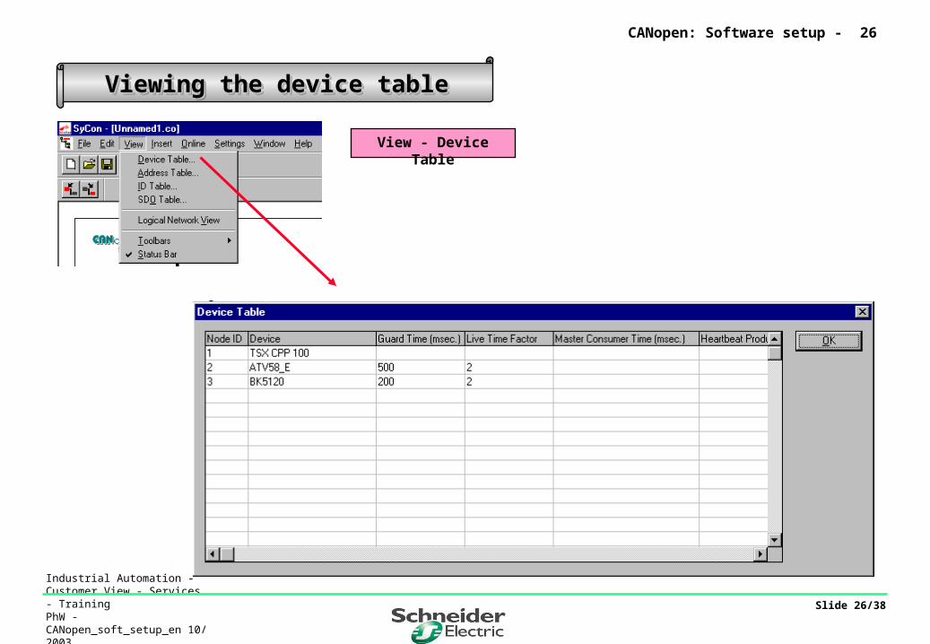
Viewing the device tableViewing the device tableViewing the device tableViewing the device table
CANopen: Software setup - 26
View - Device Table
Industrial Automation - Customer View - Services - TrainingPhW - CANopen_soft_setup_en 10/ 2003
Slide 27/38
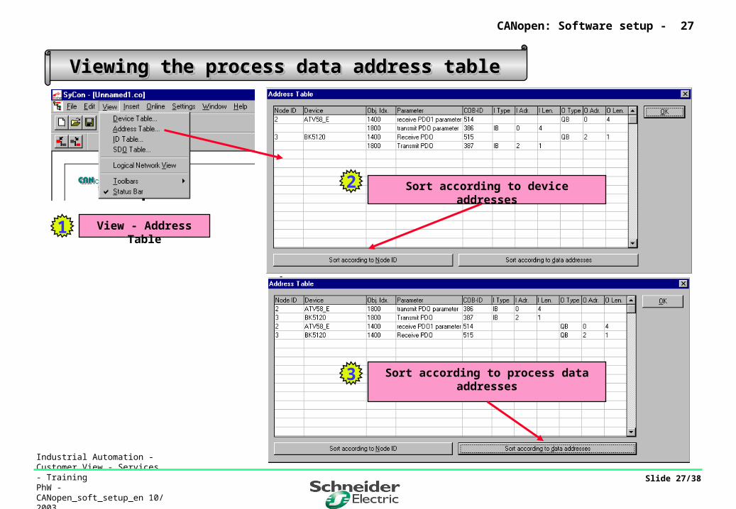
Viewing the process data address tableViewing the process data address tableViewing the process data address tableViewing the process data address table
CANopen: Software setup - 27
View - Address Table
Sort according to device addresses
Sort according to process data addresses
1
2
3
Industrial Automation - Customer View - Services - TrainingPhW - CANopen_soft_setup_en 10/ 2003
Slide 28/38
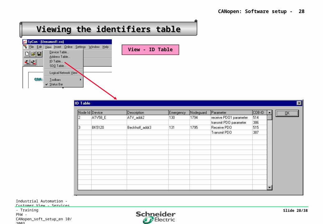
Viewing the identifiers tableViewing the identifiers tableViewing the identifiers tableViewing the identifiers table
CANopen: Software setup - 28
View - ID Table

Industrial Automation - Customer View - Services - TrainingPhW - CANopen_soft_setup_en 10/ 2003
Slide 29/38
Viewing the table of devices adapted by SDOViewing the table of devices adapted by SDOViewing the table of devices adapted by SDOViewing the table of devices adapted by SDO
CANopen: Software setup - 29
View - SDO Table

Industrial Automation - Customer View - Services - TrainingPhW - CANopen_soft_setup_en 10/ 2003
Slide 30/38
Saving the Sycon configurationSaving the Sycon configurationSaving the Sycon configurationSaving the Sycon configuration
Back
File - Save As1
CANopen: Software setup - 30
Screencam 8Enter the name and click Save2

Industrial Automation - Customer View - Services - TrainingPhW - CANopen_soft_setup_en 10/ 2003
Slide 31/38
Selecting the configuration file in PL7 and saving itSelecting the configuration file in PL7 and saving itSelecting the configuration file in PL7 and saving itSelecting the configuration file in PL7 and saving it
CANopen: Software setup - 31
BackScreencam 9
ClickSelect Database
1
Select the configuration file
****.co in the
Hilscher/Sycon/Project directory
2
Click Open3
If the number of input and output words
is inconsistent with the Sycon
configuration, an error message is
generated
Industrial Automation - Customer View - Services - TrainingPhW - CANopen_soft_setup_en 10/ 2003
Slide 32/38
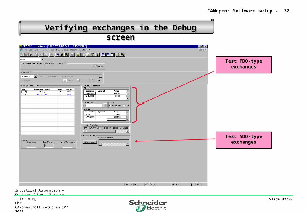
Verifying exchanges in the Debug screenVerifying exchanges in the Debug screenVerifying exchanges in the Debug screenVerifying exchanges in the Debug screen
Test PDO-type exchanges
Test SDO-type exchanges
CANopen: Software setup - 32

Industrial Automation - Customer View - Services - TrainingPhW - CANopen_soft_setup_en 10/ 2003
Slide 33/38
Interfacing with the applicationInterfacing with the applicationInterfacing with the applicationInterfacing with the application
Implicit objects:%MW:PDO input/output variables(for ATV58 2 status words: ETAD and RFRD, and 2 command words: CMDD and LFRD)
%Iy.MOD.ERR and %Iy.1.ERR: 2 input bits for module error and channel error
%IWy.1.0 to %IWy.1.23: 24 input words providing diagnostic information about the status of the channel, nodes, latest error codes, etc.
%QWy.1.0: 1 output word for activating the configuration and PDO exchanges and for reinitialising error tables.
CANopen: Software setup - 33
Industrial Automation - Customer View - Services - TrainingPhW - CANopen_soft_setup_en 10/ 2003
Slide 34/38
Interfacing with the applicationInterfacing with the applicationInterfacing with the applicationInterfacing with the application
Explicit object:
READ_STS %Chy.1
%Mwy.1.2:Input variable providing diagnostic information about the status of the master card.
CANopen: Software setup - 34

Industrial Automation - Customer View - Services - TrainingPhW - CANopen_soft_setup_en 10/ 2003
Slide 35/38
Interfacing with the applicationInterfacing with the applicationInterfacing with the applicationInterfacing with the application
Communication functions available for use:
WRITE_VAR and READ_VAR (ADR#y.1.SYS, ’SDO’,index:subindex,NodeID, %MWi:L,%MWk:4)For accessing SDO variables
SEND_REQ(ADR#y.1.SYS, 16#9F, %MWi:L, %MWj:L, %MWk:4)For accessing link layer PDUs
SEND_REQ(ADR#y.1.SYS, 16#0F, %MWi:L, %MWj:L, %MWk:4)For accessing the identification and status of the master card
SEND_REQ(ADR#y.1.SYS, 16#31, %MWi:L, %MWj:L, %MWk:4)For running diagnostics on a node, or checking the version and status of the CANopen master card, or reading the message handling error log
CANopen: Software setup - 35
Industrial Automation - Customer View - Services - TrainingPhW - CANopen_soft_setup_en 10/ 2003
Slide 36/38
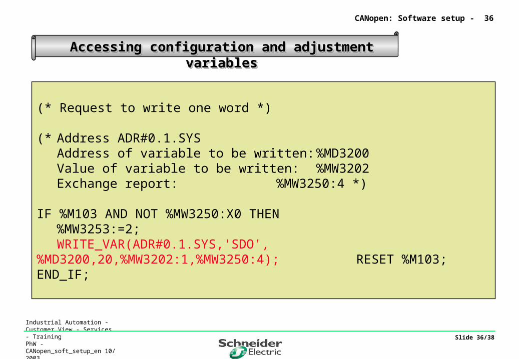
Accessing configuration and adjustment variablesAccessing configuration and adjustment variablesAccessing configuration and adjustment variablesAccessing configuration and adjustment variables
(* Request to write one word *)
(* Address ADR#0.1.SYSAddress of variable to be written: %MD3200Value of variable to be written: %MW3202Exchange report: %MW3250:4 *)
IF %M103 AND NOT %MW3250:X0 THEN%MW3253:=2; WRITE_VAR(ADR#0.1.SYS,'SDO',%MD3200,20,%MW3202:1,%MW3250:4);RESET %M103;
END_IF;
CANopen: Software setup - 36

Industrial Automation - Customer View - Services - TrainingPhW - CANopen_soft_setup_en 10/ 2003
Slide 37/38
Accessing configuration and adjustment variablesAccessing configuration and adjustment variablesAccessing configuration and adjustment variablesAccessing configuration and adjustment variables
(* Request to read one word *)(* Address ADR#0.1.SYS
Address of variable to read: %MD3220Value of variable read: %MW3222Exchange report: %MW3260:4 *)
IF %M104 AND NOT %MW3260:X0 THENREAD_VAR(ADR#0.1.SYS,'SDO',%MD3220,20,%MW3222:1,%MW3260:4);RESET %M104;
END_IF;
CANopen: Software setup - 37

Industrial Automation - Customer View - Services - TrainingPhW - CANopen_soft_setup_en 10/ 2003
Slide 38/38
Accessing diagnostic variablesAccessing diagnostic variablesAccessing diagnostic variablesAccessing diagnostic variables
(* Update variable %MW0.1.2 *)IF %MW200=1 THEN READ_STS %CH0.1;END_IF;!(* Read explicit DIAGNOSTIC exchange words *)(*Address ADR#0.1.SYS Type of diagnostic object : %MW3301
1 to 127 = node diagnostics128 = master card diagnostics130 = message handling error log
Start address in diagnostic table: %MW3302 Length of diagnostic to read : %MW3303 Receive table : %MW3310:20 Exchange report : %MW3350:4 *)
IF %MW3300=1 AND NOT %MW3350:X0 THEN %MW3300:=0;%MW3353:=6;SEND_REQ(ADR#0.1.SYS,16#0031,%MW3301:3,%MW3310:20,%MW3350:4);END_IF;
CANopen: Software setup - 38