Canister Handling Facility Description Document
118
Transcript of Canister Handling Facility Description Document
Canister Handling Facility Description Document
190-3YD-CH00-00100-000-002 ii April 2005
DISCLAIMER
This report was prepared as an account of work sponsored by an agency of the United States Government. Neither the United States Government nor any agency thereof, nor any of their employees, nor any of their contractors,subcontractors or their employees, makes any warranty, express or implied, or assumes any legal liability orresponsibility for the accuracy, completeness, or any third party’s use or the results of such use of any information,apparatus, product, or process disclosed, or represents that its use would not infringe privately owned rights.Reference herein to any specific commercial product, process, or service by trade name, trademark, manufacturer,or otherwise, does not necessarily constitute or imply its endorsement, recommendation, or favoring by the UnitedStates Government or any agency thereof or its contractors or subcontractors. The views and opinions of authors expressed herein do not necessarily state or reflect those of the United States Government or any agency thereof.
BSC Facility Description Document
Change History Complete only applicable items
11. Page iv of 118
12. FDD Title Canister Handling Facility Description Document 13. DI 190-3YD-CH00-00100-000-002 14. Revision No. 15. Description of Change
000 Initial Issue – This revision of the Facility Description Document presents the preliminary requirements and a brief description of the facility to guide License Application design development.
001 Revised to update and incorporate changes to design. Added second waste package closure cell. Added supporting mechanical equipment envelope calculations and drawings. Reformatted FDD style. Updated references. Updated interface information for interfacing systems and facilities. Added discussion on drop height mitigation. This entire FDD has been revised.
002 Revised to update requirement and design information. Removed drawings from reference list. Removed discussion of CHF Central Control Center. MSC changed to aging cask. Added figures depicting operations block flow diagram and maximum canister inventory. Incorporated nomenclature changes, as applicable, for various structures, systems, and components.
Canister Handling Facility Description Document
190-3YD-CH00-00100-000-002 v April 2005
CONTENTS Page
ACRONYMS................................................................................................................................ vii
1. INTRODUCTION ................................................................................................................. 1-1 1.1 FACILITY IDENTIFICATION ................................................................................... 1-1 1.2 LIMITATIONS OF THIS FACILITY DESCRIPTION DOCUMENT....................... 1-3 1.3 OWNERSHIP OF THIS FACILITY DESCRIPTION DOCUMENT ......................... 1-3
2. OVERVIEW .......................................................................................................................... 2-1 2.1 FACILITY FUNCTIONS............................................................................................. 2-1 2.2 FACILITY CLASSIFICATION................................................................................... 2-2 2.3 OPERATIONAL OVERVIEW .................................................................................... 2-2
3. REQUIREMENTS AND BASES ......................................................................................... 3-1 3.1 GENERAL REQUIREMENTS.................................................................................... 3-1 3.2 SPECIAL REQUIREMENTS AND BASES ............................................................. 3-10 3.3 ENGINEERING DISCIPLINARY REQUIREMENTS AND BASES...................... 3-12 3.4 TESTING AND MAINTENANCE REQUIREMENTS AND BASES..................... 3-16 3.5 OTHER REQUIREMENTS AND BASES ................................................................ 3-16
4. FACILITY DESCRIPTION .................................................................................................. 4-1 4.1 CONFIGURATION INFORMATION......................................................................... 4-1 4.2 OPERATIONS............................................................................................................ 4-28 4.3 TESTING AND MAINTENANCE............................................................................ 4-31
5. REFERENCES ...................................................................................................................... 5-1 5.1 DOCUMENTS CITED................................................................................................. 5-1 5.2 CODES, STANDARDS, REGULATIONS, AND PROCEDURES............................ 5-4 5.3 DATA TRACKING NUMBERS ................................................................................. 5-5 5.4 SOFTWARE CODES................................................................................................... 5-5
APPENDIX A GLOSSARY.................................................................................................... A-1
APPENDIX B KEY FACILITY CHARTS, DIAGRAMS, DRAWINGS, AND LISTS ........B-1
APPENDIX C LIST OF FACILITY PROCEDURES.............................................................C-1
Canister Handling Facility Description Document
190-3YD-CH00-00100-000-002 vi April 2005
FIGURES
Page
Figure B-1. Canister Handling Facility Ground Floor Plan...............................................B-15 Figure B-2. Canister Handling Facility Second Floor Plan ...............................................B-17 Figure B-3. Canister Handling Facility Third Floor Plan ..................................................B-19 Figure B-4. Canister Handling Facility Sections ...............................................................B-21 Figure B-5. Maximum Canister Inventory of SNF and HLW in the Canister .......................... Handling Facility ............................................................................................B-23 Figure B-6. Canister Handling Facility Operations Block Flow Diagram.........................B-25 Figure B-7. Material Flow Path Diagram...........................................................................B-27 Figure B-8. Waste Package Drop Mitigation .....................................................................B-29 Figure B-9. Naval Cask Lifting Arrangement....................................................................B-31
TABLES
Page
Table 2-1. Canister Handling Facility Q-List .................................................................... 2-2 Table 4-1. Natural Phenomena......................................................................................... 4-28 Table B-1. Commercial Vertical DPCs for Potential CHF Handling.................................B-6 Table B-2. Canisters and Transfer Interface .....................................................................B-12
Canister Handling Facility Description Document
190-3YD-CH00-00100-000-002 vii April 2005
ACRONYMS
ACI American Concrete Institute AISC American Institute of Steel Construction ALARA as low as is reasonably achievable ANSI American National Standards Institute ASCE American Society of Civil Engineers
BDBGM beyond design basis ground motion
CHF Canister Handling Facility
DBGM design basis ground motion DOE U.S. Department of Energy DPC dual-purpose canister
F&OR Functional and Operational Requirements FDD facility description document
HLW high-level radioactive waste HVAC heating, ventilation, and air-conditioning
ITS important to safety
LLW low-level radioactive waste LWT legal-weight truck
MCO multicanister overpack MPC multipurpose canister
OWT overweight truck
PDC Project Design Criteria Document
SNF spent nuclear fuel SRTC site rail transfer cart SSCs structures, systems, and components
TCRRF Transportation Cask Receipt/Return Facility
Canister Handling Facility Description Document
190-3YD-CH00-00100-000-002 viii April 2005
INTENTIONALLY LEFT BLANK
Canister Handling Facility Description Document
190-3YD-CH00-00100-000-002 1-1 April 2005
1. INTRODUCTION
The purpose of this facility description document (FDD) is to establish requirements and associated bases that drive the design of the Canister Handling Facility (CHF), which will allow the design effort to proceed to license application. This FDD will be revised at strategic points as the design matures. This FDD identifies the requirements and describes the facility design, as it currently exists, with emphasis on attributes of the design provided to meet the requirements. This FDD is an engineering tool for design control; accordingly, the primary audience and users are design engineers. This FDD is part of an iterative design process. It leads the design process with regard to the flowdown of upper tier requirements onto the facility. Knowledge of these requirements is essential in performing the design process. The FDD follows the design with regard to the description of the facility. The description provided in this FDD reflects the current results of the design process.
Functional and operational requirements applicable to this facility were obtained from Project Functional and Operational Requirements (F&OR) (Curry 2004 [DIRS 170557]). Other requirements that support the design process were taken from documents such as Project Design Criteria Document (PDC) (BSC 2004 [DIRS 171599]), Canister Handling Facility Fire Hazard Analysis (BSC 2005 [DIRS 168814]), and Nuclear Safety Design Bases for License Application (BSC 2005 [DIRS 171512]). These documents address requirements in the Project Requirements Document (Canori and Leitner 2003 [DIRS 166275]).
This FDD includes several appendices. Appendix A is a glossary; Appendix B is a lists of key facility charts, diagrams, drawings, lists, and additional supporting information; and Appendix C is reserved for a list of procedures that will be used to operate the facility.
1.1 FACILITY IDENTIFICATION
The CHF provides the space, layout, and structures that only support handling sealed canisters. The CHF is located on the surface at the North Portal pad of the repository. The CHF provides space and layout to support cask preparation and canister transfer operations of U.S. Department of Energy (DOE) spent nuclear fuel (SNF), high-level radioactive waste (HLW), naval canisters, and multicanister overpacks (MCOs). The CHF supports canister transfer to waste packages, closure of waste packages, and loading of waste packages onto the waste package transporter for underground emplacement. The CHF also provides the capability to load commercial vertical dual-purpose canisters (DPCs) into aging casks. The facility may handle multipurpose canisters (MPCs), if and when MPCs become available. The CHF provides a limited throughput capacity for handling only sealed canisters. In Section B4.9, Table B-2 summarizes canister handling operations in the CHF by indicating the types of canisters handled (DOE SNF, HLW, naval canisters, etc.), and where they may be placed (e.g., waste package, aging cask, or canister staging pit).
The CHF is divided into areas for waste processing operations and areas to support these activities. Waste processing activities are performed in the entrance vestibule (Room 1036), the canister transfer cell (Room 1033), below grade waste handling pits, the waste package positioning cell, the waste package closure cell, and the exit vestibule. Waste handling support areas include equipment rooms, crane maintenance rooms, tool storage areas, and areas to
Canister Handling Facility Description Document
190-3YD-CH00-00100-000-002 1-2 April 2005
support essential personnel. The CHF has a limited-capacity for in-process waste staging, consisting of below-grade shielded staging for 10 DOE SNF and HLW canisters. The maximum canister inventory present at any one time in the CHF is defined by the number of casks and waste packages that could be present in the facility combined with the staged DOE SNF or HLW canisters. Figure B-5 illustrates that up to two loaded casks, four loaded waste packages, and ten DOE SNF or HLW canisters in the staging pits is the maximum CHF inventory.
The facility includes space for a local control and communications center for monitoring CHF operations. The space in the CHF is to be used to support the control and communications equipment required for the CHF and for interfacing with the repository Central Control Center Facility.
The CHF operating galleries are located adjacent to the canister transfer cell (Room 1033). The operating galleries are separated from the canister transfer cell by thick, reinforced concrete shield walls. The shield walls and windows protect personnel who remotely operate the waste transfer system equipment. The building maintains a suitable environment for personnel and equipment; protects the structures, systems, and components (SSCs) within the facility from natural and induced environments; limits the spread of contamination; and provides radiological protection for personnel. The facility provides space and layout for SSCs that are important to safety (ITS), and for operations control and monitoring, safeguards and security, fire protection, ventilation, and utility systems.
The CHF integrates waste handling systems within the protective structure to support the throughput rates established for waste emplacement. The facility also provides shielding, layout, and other design features to limit personnel radiation exposure to levels that are as low as is reasonably achievable (ALARA).
The CHF interfaces with repository systems that perform or support waste handling operations. The CHF interfaces with the following systems and facilities:
Waste Handling Systems
• Cask receipt and return system • Cask and waste package preparation system • DOE and commercial waste package system • Emplacement and retrieval system • Naval spent nuclear fuel waste package system • Non-nuclear handling system • Remediation system • Aging system • SNF/HLW transfer system • Waste package closure system.
Infrastructure Systems
• Communications system • Digital control and management information system
Canister Handling Facility Description Document
190-3YD-CH00-00100-000-002 1-3 April 2005
• Electrical power system • Electrical support system • Environmental and meteorological monitoring system • Fire protection system • Heating, ventilation, and air-conditioning (HVAC) plant heating and cooling system • Low-level radioactive waste generating system • Low-level radioactive waste management system • Non-radiological waste management system • Plant services system • Radiation and radiological monitoring system • Safeguards and security system • Surface industrial HVAC system • Surface nuclear HVAC system.
Facilities
• Balance of Plant Facility.
Additional information for the above systems and facility may be found in the documents that are listed in Section B3.2.
1.2 LIMITATIONS OF THIS FACILITY DESCRIPTION DOCUMENT
This FDD may include assumptions, preliminary information, and to be verified values, as appropriate, to the current level of design development. Additionally, requirements or descriptions that are stated as to be determined, or are expected at a later phase of the design, will be described as such.
When this version was approved, the design status was such that the conceptual design had been completed and the preliminary design had begun. As design documents (e.g., calculations, drawings, specifications) are completed, this FDD will be updated.
1.3 OWNERSHIP OF THIS FACILITY DESCRIPTION DOCUMENT
This Canister Handling Facility Description Document is owned by the CHF, Cask and Waste Package Receipt, and Aging Project group of the Design and Engineering Organization.

Canister Handling Facility Description Document
190-3YD-CH00-00100-000-002 1-4 April 2005
INTENTIONALLY LEFT BLANK
Canister Handling Facility Description Document
190-3YD-CH00-00100-000-002 2-1 April 2005
2. OVERVIEW
This section includes functions of the CHF that have been derived from the F&OR (Curry 2004 [DIRS 170557]). These are the primary CHF functions that support the development and derivation of CHF functional requirements in Section 3.1.1. This section also describes a preliminary determination of the CHF safety category in Section 2.2, and an operational overview in Section 2.3.
2.1 FACILITY FUNCTIONS
The F&OR describes the functions and operations that must be accomplished in the successful execution of the repository mission. The CHF functions, and the functions performed by the waste handling systems, infrastructure systems, and other facilities, fulfill the repository functions as established by the F&OR. With regard to facilities, the F&OR describes the following operational and performance requirements that facilities must accomplish:
• The repository shall control all aspects of SNF and HLW handling operations, including material and equipment movement, criticality, quality of sealing, radiological confinement, and nuclear material inventories. [F&OR 1.1-6]
• The repository shall provide sufficient space and means to maintain physical services. [F&OR 1.4.2-3]
• The repository shall provide sufficient space and means to maintain equipment. [F&OR 1.4.2-4]
The mission of the repository is to dispose of SNF and HLW. This involves many operations and activities that cannot be performed without the provision and maintenance of a robust infrastructure [F&OR 1.4]. Requirements for decontamination and decommissioning of surface facilities will be developed in a future revision of the F&OR, but the CHF design must recognize this mission requirement. [Function 2.1.5] [F&OR 1.3.2]
To support the successful execution of the missions of the repository as stated above, the CHF must carry out the functions listed below.
2.1.1 Provide Space, Layout, and Structure
The CHF provides space, structures, and enclosures for systems to support cask and waste package preparation, canister transfer operations, closure of waste packages, loading of aging casks for movement to the aging system, and loading of waste packages onto waste package transporters for emplacement (Table B-2 in Section B4.9). [F&OR 1.1-6, 1.4.2-3, and 1.4.2-4]
2.1.2 Provide for Maintenance and Support
The CHF provides space, structures, and enclosures for maintenance and other support operations associated with canister transfer activities. [F&OR 1.4-2]
Canister Handling Facility Description Document
190-3YD-CH00-00100-000-002 2-2 April 2005
2.1.3 Protect SSCs
The CHF provides protection for SSCs in the building from internal and external hazards. [F&OR 1.4 and 1.1-4]
2.1.4 Provide Shielding and Radiation Controls
The CHF provides shielding and radiation controls so that radiation exposures to personnel are maintained ALARA (Curry 2004 [DIRS 170557], p. 2).
2.1.5 Provide for Decontamination and Decommission
The CHF shall incorporate design features that will facilitate decontamination and decommissioning activities at the end of the facility mission. [F&OR 1.3.2]
2.2 FACILITY CLASSIFICATION
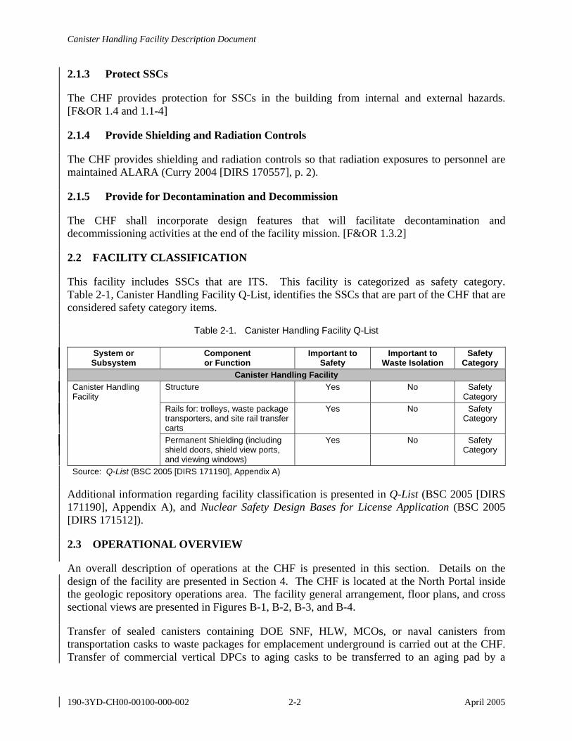
This facility includes SSCs that are ITS. This facility is categorized as safety category. Table 2-1, Canister Handling Facility Q-List, identifies the SSCs that are part of the CHF that are considered safety category items.
Table 2-1. Canister Handling Facility Q-List
System or Subsystem
Component or Function
Important to Safety
Important to Waste Isolation
Safety Category
Canister Handling Facility Canister Handling Facility
Structure Yes No Safety Category
Rails for: trolleys, waste package transporters, and site rail transfer carts
Yes No Safety Category
Permanent Shielding (including shield doors, shield view ports, and viewing windows)
Yes No Safety Category
Source: Q-List (BSC 2005 [DIRS 171190], Appendix A)
Additional information regarding facility classification is presented in Q-List (BSC 2005 [DIRS 171190], Appendix A), and Nuclear Safety Design Bases for License Application (BSC 2005 [DIRS 171512]).
2.3 OPERATIONAL OVERVIEW
An overall description of operations at the CHF is presented in this section. Details on the design of the facility are presented in Section 4. The CHF is located at the North Portal inside the geologic repository operations area. The facility general arrangement, floor plans, and cross sectional views are presented in Figures B-1, B-2, B-3, and B-4.
Transfer of sealed canisters containing DOE SNF, HLW, MCOs, or naval canisters from transportation casks to waste packages for emplacement underground is carried out at the CHF. Transfer of commercial vertical DPCs to aging casks to be transferred to an aging pad by a
Canister Handling Facility Description Document
190-3YD-CH00-00100-000-002 2-3 April 2005
crawler is also carried out in this facility. The CHF is designed to handle only waste contained in sealed canisters.
As part of its normal operations, the CHF has limited capacity to perform in-process remediation on casks, canisters, and waste packages. Remediation is generally limited to those operations required to allow the waste form to be safely handled and placed into a waste package. In the event a nonconforming item cannot be remediated by the CHF, or the item cannot be remediated in a timely manner by the CHF, the nonconforming item is sent to the remediation system in the Dry Transfer Facility.
Nonconformities associated with casks that can be addressed in the CHF include problems with bolts, lids, and trunnions. The nature and extent of the nonconformity determines how and where remediation is performed. Generally, if the cask does not need to be opened to correct the problem, remediation is carried out in the canister transfer cell (Room 1033) or the cask preparation pit (P002). If the cask needs to be opened, it is returned to a state where it can be safely transported and is sent to the remediation system in the Dry Transfer Facility.
Nonconformities associated with canisters that can be addressed in the CHF include problems associated with attachment of lifting fixtures and physical configuration of the canisters. Remediation of canisters is carried out in the canister transfer cell (Room 1033) or the cask preparation pit (P002). The CHF does not have the capability to open a canister or handle a canister with a breach of its containment boundary.
Minor remediation of waste packages is performed in the waste package closure cells (Rooms 2010 and 2032). The waste package closure cells in the CHF have a limited capability to remove weld defects and perform minor weld repair.
The CHF is important for the overall operation of the repository. In conjunction with the other waste handling facilities, the CHF provides operational flexibility and the capability of processing the expected types of canistered waste. As such, the CHF interfaces with many on-site systems and facilities, as discussed in Section 4.1.2. Major waste processing activities within the CHF are:
• Cask and waste package preparation (Sections 2.3.1 and 4.1.4.1)
• Canister transfer (Sections 2.3.2 and 4.1.4.2)
− Canister transfer to waste package − Commercial vertical DPC transfer to an aging cask − Canister transfer to a canister staging pit.
• Waste package closure (Sections 2.3.3 and 4.1.4.3)
• Waste package loadout (Sections 2.3.4 and 4.1.4.4)
Canister Handling Facility Description Document
190-3YD-CH00-00100-000-002 2-4 April 2005
• Cask restoration (Sections 2.3.5 and 4.1.4.5)
− Empty transportation cask restoration for return to the cask receipt and return system − Loaded aging cask restoration for processing by the aging system − Loaded off-normal transportation cask restoration.
These activities are summarized in the following sections. The sequence of major activities is illustrated in an operations block flow diagram (Figure B-6) and in a material flow path diagram (Figure B-7). Specific areas within the CHF where these activities are performed, and the systems that perform these activities, are discussed in Sections 4.1.4.1 through 4.1.4.5.
2.3.1 Cask and Waste Package Preparation System
This overview section summarizes the activities of transportation cask preparation, aging cask preparation, and waste package preparation. The cask and waste package preparation system operation is further discussed in Section 4.1.4.1, and space details are presented in Section B4.2.
Transportation Cask Preparation—Prior to receiving transportation casks, the appropriate handling tools and pit pedestals are staged in the CHF. The shielded pit covers are removed and an appropriate pedestal and pit crush pad are placed in the cask preparation pit (P002). The auxiliary hook on the 200-ton cask handling crane is used to handle the pit pedestal and pit crush pads.
A transportation cask arrives on a site rail transfer cart (SRTC), overweight truck (OWT), or legal-weight truck (LWT). The cask is moved into the entrance vestibule (Room 1036) and inspected to confirm the cask type. Impact limiters are usually removed, as necessary, using the 20-ton entrance vestibule crane. As cask handling procedures are developed, it may be necessary to move some transportation casks into the canister transfer cell (Room 1033) to remove impact limiters. If personnel barriers were not removed in the Transportation Cask Receipt/Return Facility (TCRRF), they are removed in the entrance vestibule or canister transfer cell. The cask is inspected and surveyed and, if contamination is found, it is dispositioned.
The cask is then moved into the canister transfer cell (Room 1033) where the tie-downs and stabilizers are removed. The appropriate yoke is selected and the cask is upended, lifted, and positioned into the cask preparation pit (P002) using the 200-ton cask handling crane.
A moveable platform for cask preparation is positioned over the cask preparation pit (P002). The platform provides shielding and allows work to be performed on the cask lid. The cask cavity gas is sampled, internal pressure is equalized to atmospheric, bolts are detorqued, and the cask is ready for canister transfer. The moveable platform is returned to its staging area in the canister transfer cell (Room 1033).
Prior to removing a transportation cask lid, the proper lifting fixture is attached to the lid. The grapple for transferring the cask lid is attached to the auxiliary hook of the 100-ton waste package and canister handling crane. The appropriate grapple for canister transfer is installed on the main hook of the 100-ton crane. For a transportation cask containing a naval canister or a commercial vertical DPC, an additional step is required after the transportation cask lid is
Canister Handling Facility Description Document
190-3YD-CH00-00100-000-002 2-5 April 2005
removed. A lift fixture with pintle is attached to the top of the naval canister or DPC so that the grapple can remotely lift the canister. Personnel entry can occur during different stages of the process to change out grapples and yokes if necessary when radiation sources are shielded.
Waste Package Preparation—Handling tools for the specific waste package are staged inside the canister transfer cell (Room 1033). An empty waste package with the trunnion collars installed and scheduled for processing is moved vertically on an SRTC from the TCRRF through the entrance vestibule (Room 1036) to the canister transfer cell. The CHF also has the capability of receiving waste packages on an LWT or OWT. Waste package tie-downs are removed. Waste package outer lids, middle lids, and welding wire are delivered to the closure support rooms (Rooms 2007 or 2029). The waste package is delivered to the canister transfer cell with its inner lid and spread ring. The shielded pit covers are removed and an appropriate pedestal and pit crush pad are placed in a waste package loading pit (P003 or P004). The auxiliary hook on the 100-ton crane is used to handle the pit pedestal and the pit crush pads. The empty waste package is lifted by the 100-ton waste package and canister handling crane, positioned into a waste package loading pit, and prepared for canister transfer. The crane is then used to remove and stage the waste package inner lid using the waste package lid grapple. An appropriate pedestal is placed on the waste package trolley by a crane auxiliary hook to prepare for receiving the loaded waste package. After canister transfer the waste package trolley delivers the waste package to the waste package positioning cell in preparation for waste package closure operations.
Aging Cask Preparation—If a commercial vertical DPC is to be sent to the aging system, the DPC is transferred to an aging cask. An empty aging cask is delivered on an SRTC, though the CHF is sized to receive aging casks on LWTs, or OWTs. The aging cask is moved through the entrance vestibule (Room 1036) into the canister transfer cell (Room 1033). Tie-downs are removed, and the empty aging cask is positioned into an aging cask loading pit (P003 or P004), and prepared for canister transfer. Handling the aging cask is similar to a transportation cask except the aging cask is not expected to have impact limiters or a personnel barrier.
During cask and waste package preparation activities, the SRTC, LWT, or OWT is removed from the canister transfer cell. Canister transfer is initiated after preparation activities are concluded.
2.3.2 Canister Transfer
Canister transfer operations occur in the canister transfer cell (Room 1033) and are conducted remotely behind shielded walls, doors, and windows in operating galleries. The canister transfer cell includes a cask preparation pit (P002) and two aging cask and waste package loading pits (P003 and P004). The east end of the canister transfer cell includes a canister staging pit (P001). The west side includes a waste package turntable, a waste package tilting machine, and a waste package collar removal machine. A 100-ton waste package and canister handling crane and a 200-ton cask handling crane are bridge cranes located overhead. Canister transfer operations are discussed in further detail in Section 4.1.4.2.
Canister transfer operations only occur in a portion of the canister transfer cell (Room 1033). Operations in the canister transfer area are performed remotely from adjacent shielded galleries.
Canister Handling Facility Description Document
190-3YD-CH00-00100-000-002 2-6 April 2005
Operators use shield windows, closed-circuit television, and the remotely controlled overhead bridge cranes to perform canister transfer functions. Shield doors into the canister transfer cell are secured and verification that all personnel have exited the canister transfer cell is performed prior to initiating canister transfer.
The 100-ton capacity waste package and canister handling crane and canister lifting grapple are used to engage and lift each canister one at a time (see Appendix A for definitions of grapple and yoke as used in this FDD). Canisters are transferred only after verifying that the canister is within established mechanical handling thermal operating parameters. The canister is lifted and moved to a location over the prepositioned waste package in a waste package loading pit (P003 or P004). The crane is secured and the canister is lowered into the waste package. For a small DOE SNF canister, small HLW canister, or MCO, several transfer operations from one or more transportation casks are required to fill a waste package. If a waste package is filled before a cask is emptied, the remaining DOE SNF or HLW canisters can be moved to the canister staging pit (P001), or the transportation cask containing the remaining canisters can be shielded in the cask preparation pit (P002) until a new waste package is prepared. For naval canisters, one transfer is required to load the canister into the waste package; these canisters are preloaded to meet the design basis thermal limit per waste package.
When a DOE SNF or HLW canister is not to be immediately loaded into a waste package, the canister can be staged in the shielded canister staging pit (P001). The shield plug over the designated staging tube is removed. After the canister has been transferred to the canister staging pit, the shield plug is replaced over the staging tube.
Commercial vertical DPCs are only transferred to aging casks. Naval canisters and MCOs are only transferred to waste packages. DOE SNF and HLW are only placed in a waste package or in the canister staging pit (Table B-2 in Section B4.9). For a waste package containing a naval canister, the lift fixture with pintle must be removed prior to the inner lid being replaced and the waste package being transferred to the waste package trolley. The lift fixture with pintle must also be removed from the commercial vertical DPC after loading the DPC into an aging cask.
The waste package trolleys are located in the canister transfer cell (Room 1033) at the entrance to each waste package positioning cell on the ground floor. A loaded unsealed waste package, with the inner lid secured in place, is transferred from a waste package loading pit (P003 or P004) to a waste package trolley using the 100-ton crane. The waste package is secured on the trolley and transferred into a waste package positioning cell. Waste package welding and other closure operations are performed in a waste package closure cell. After closure, the waste package trolley is used to transfer the waste package back to the canister transfer cell where the 100-ton crane is used to move the waste package to the waste package loadout area.
2.3.3 Waste Package Closure
A loaded waste package is moved into one of two waste package positioning cells (Room 1011 or 1042) for closure operations. Closure operations include welding, nondestructive examination, inerting, stress mitigation, and related operations. After a loaded waste package is received in a waste package closure cell, the inner lid and spread ring are seal welded in place, the waste package inner vessel is evacuated and filled with inert gas, the middle and outer lids
Canister Handling Facility Description Document
190-3YD-CH00-00100-000-002 2-7 April 2005
are welded in place, the welds are nondestructively examined, and residual stresses on the outer lid weld are mitigated. Operating principles for the waste package closure system are further explained in Section 4.1.4.3.
The waste package closure operations are performed remotely using remote welding, examination, inerting, and stress mitigation equipment. Operators are positioned in the shielded closure operating gallery located adjacent to the closure cell. Periodic adjustments, repairs, and replacements to this equipment will be necessary, so most equipment has the capability to either be removed from the waste package closure cells and lifted into the maintenance areas located adjacent to and directly above the cells, or placed in a glove box located in a waste package closure support room. The remote disengagement capability eliminates the need for personnel to enter the waste package closure cells when a high radiation source, the loaded waste package, is present during operations. After waste package closure, the waste package is moved back into the canister transfer cell for waste package loadout.
2.3.4 Waste Package Loadout
Prior to moving a waste package out of a waste package positioning cell, the waste package transporter is moved into the loadout area through the exit vestibule. The shield doors on the transporter are opened to receive the sealed waste package and the locomotive exits the canister transfer cell. The waste package trolley moves the sealed waste package out of the waste package closure area into the waste package loadout area. The 100-ton crane is used to lift and move the waste package to the survey area where a confirmatory waste package surface contamination survey is performed. Additional information regarding waste package loadout is found in Section 4.1.4.4.
Waste packages are surveyed for surface contamination using a wall-mounted, remotely operated manipulator and the results of the survey are recorded for the waste package. The 100-ton crane is then used to lift the waste package and transfer it to the waste package tilting machine. The lower waste package trunnions are engaged with the tilt machine to start the waste package tilt operation. The waste package is then down-ended to a horizontal orientation. The waste package is remotely placed onto the waste package emplacement pallet, located on the waste package turntable, using the crane and the waste package tilting machine. The turntable with the waste package is aligned with the collar removal machine for remote removal of the waste package trunnion collars.
The waste package lifting yoke is then remotely replaced with the pallet lifting yoke. The 100-ton crane is positioned over the waste package and emplacement pallet. The crane then transfers the waste package resting on the emplacement pallet to the waste package transporter bedplate. The waste package, emplacement pallet, and bedplate are retracted into the waste package transporter, and the transporter shield doors are remotely closed. With the transporter shield doors closed, personnel reenter the canister transfer cell (Room 1033) and the waste package transporter leaves the CHF.
Canister Handling Facility Description Document
190-3YD-CH00-00100-000-002 2-8 April 2005
2.3.5 Cask Restoration
After canister transfer operations are complete, cask restoration prepares the transportation cask or aging cask for leaving the CHF. Cask restoration is the term used to describe a cask leaving the CHF.
The cask lid is installed and bolted. If applicable, a leak test is performed on the cask. For an aging cask containing a commercial vertical DPC, the lift fixture with pintle must be removed from the DPC prior to the aging cask lid being installed. Loaded aging casks go through additional processing steps, including filling the cask with an inert gas and performing seal leak tests, as necessary. Cask restoration is discussed in further detail in Section 4.1.4.5.
The SRTC, LWT, or OWT is moved back into the canister transfer cell (Room 1033). An empty transportation cask is placed on the SRTC, LWT, or OWT using the 200-ton cask handling crane and proper yoke. The aging cask is loaded onto an SRTC. Radiation surveys are performed prior to exiting the building. No significant level of contamination is expected on cask surfaces. Impact limiters and personnel barriers are reinstalled (if required) and the empty transportation cask is returned to the cask receipt and return system. The loaded aging cask is moved outside by the SRTC where the aging system crawler retrieves the cask and delivers it to an aging pad.
If a loaded off-normal transportation cask cannot be unloaded and must be removed from the CHF, it is placed back on the SRTC, LWT, or OWT and exits the facility in the reverse order that it entered. The off-normal cask is delivered to the remediation system or staged in a holding area while a disposition plan is developed.
Canister Handling Facility Description Document
190-3YD-CH00-00100-000-002 3-1 April 2005
3. REQUIREMENTS AND BASES
This section lists the requirements that are necessary to ensure the functions in Section 2.1 are satisfied. Each facility functional requirement in Section 3.1.1 is traceable to a facility function in Section 2.1.
Throughout Section 3, references are made to numerous source documents. In each case, PDC refers to the Project Design Criteria Document (BSC 2004 [DIRS 171599]) and F&OR refers to the Project Functional and Operational Requirements (Curry 2004 [DIRS 170557]). More complete reference document information is provided in Section 5. Applicable Project Requirements Document requirements allocated to the Design and Engineering organization in the Requirements Allocation Matrix (Canori and Leitner 2003 [DIRS 166275], Section 6.3) are addressed in this FDD through the implementation of F&OR and PDC requirements. Applicable Project Requirements Document requirements allocated to other organizations, such as Transportation; Environmental, Safety and Health; Repository Operations, or others (Canori and Leitner 2003 [DIRS 166275], Section 6), are also included and cited as derived from the PDC and F&OR.
All requirements are categorized as external compliance requirements unless otherwise specified. Requirement category definitions for 10 CFR Part 63 [DIRS 173273], licensing, external compliance, and engineering requirements are defined and explained in Appendix A.
3.1 GENERAL REQUIREMENTS
3.1.1 Facility Functional Requirements
3.1.1.1 Safety Requirements
The safety requirements in this section are nuclear safety design bases from Nuclear Safety Design Bases for License Application (BSC 2005 [DIRS 171512], Table A-I). Other requirements that address safety issues, such as personnel protection from industrial hazards or nuclear criticality safety requirements, are presented in subsequent topical sections below. These nuclear safety requirements are considered 10 CFR Part 63 [DIRS 173273] requirements and support Functions 2.1.3 and 2.1.4.
3.1.1.1.1 Requirement: The structure shall be designed for the loads associated with a design basis extreme wind speed.
Basis: This requirement is based on ensuring that the repository meets required preclosure safety objectives as stated in the Nuclear Safety Design Bases for License Application (BSC 2005 [DIRS 171512], Table A-I). The requirement is needed to assure adequate protection for workers, the public, and the environment.
Comment: For additional information on this requirements and subsequent requirements 3.1.1.1.x, see Nuclear Safety Design Bases for License Application (BSC 2005 [DIRS 171512], Table A-I). The nuclear safety requirements are taken directly from Nuclear Safety Design Bases for License Application (BSC 2005 [DIRS 171512], Table A-I).
Canister Handling Facility Description Document
190-3YD-CH00-00100-000-002 3-2 April 2005
3.1.1.1.2 Requirement: The structure shall be designed for the loads associated with a design basis tornado maximum wind speed with a corresponding pressure drop and rate of pressure drop.
Basis: Same as Section 3.1.1.1.1.
Comment: See Section 3.3.1.2 for additional requirements that address tornado winds.
3.1.1.1.3 Requirement: The structure shall be evaluated for the effects of Spectrum II tornado missile impacts, except for the entrance and exit vestibules and the steel structures on top of the building. The evaluations shall demonstrate that the structural integrity of the CHF precludes unacceptable structural performance that would jeopardize the credited safety function of the CHF.
Basis: Same as Section 3.1.1.1.1.
Comment: See Section 3.3.1.2 for additional requirements that address tornado missiles.
3.1.1.1.4 Requirement: The roof of the structure shall be designed for the loads associated with the maximum observed hourly precipitation event (with a 100-year return period).
Basis: Same as Section 3.1.1.1.1.
3.1.1.1.5 Requirement: Facilities that could be damaged by flooding shall be located above the probable maximum flood elevation or must be appropriately protected from the probable maximum flood.
Basis: Same as Section 3.1.1.1.1.
3.1.1.1.6 Requirement: The structure shall be designed such that storm water runoff from the maximum observed hourly precipitation event (with a 100-year return period) does not enter the structure.
Basis: Same as Section 3.1.1.1.1.
3.1.1.1.7 Requirement: The roof of the structure shall be designed for the loads associated with a volcanic ash fall.
Basis: Same as Section 3.1.1.1.1.
3.1.1.1.8 Requirement: Flooding of areas of the structure where moderators are controlled shall be precluded by passive design features such as drains, flood control channels, curbs, elevated processing areas, and walls.
Basis: Same as Section 3.1.1.1.1.
3.1.1.1.9 Requirement: The CHF structure shall be designed for loading conditions associated with a design basis ground motion (DBGM)-2 seismic event. In addition, it shall be demonstrated that the CHF structure has sufficient seismic design margin to ensure that a
Canister Handling Facility Description Document
190-3YD-CH00-00100-000-002 3-3 April 2005
“no structural collapse” safety function is maintained for loading conditions associated with a beyond design basis ground motion (BDBGM) seismic event.
Basis: Same as Section 3.1.1.1.1.
Comment: Additional seismic requirements are described in Section 3.3.1.1. Additional information regarding the “no structural collapse” safety function is contained in Nuclear Safety Design Bases for License Application (BSC 2005 [DIRS 171512], Appendix B).
3.1.1.1.10 Requirement: The exterior walls of the CHF shall not be penetrated or collapsed by an F-16 aircraft crashing into an exterior wall at the speed corresponding to the 95th percentile from a probability distribution estimated from historical F-16 crashes.
Basis: Same as Section 3.1.1.1.1.
Comment: Currently the F-16 is the most common type of military aircraft flown in the vicinity of the repository, and the most likely to crash into a surface facility.
3.1.1.1.11 Requirement: Surfaces in the load paths through which loaded waste packages, standardized DOE SNF and HLW canisters, MCOs, naval canisters, DPCs, loaded transportation casks, or loaded aging casks are transferred by crane shall be kept free of structures, such as post and curbs, that could puncture a container in the event of a drop.
Basis: Same as Section 3.1.1.1.1.
3.1.1.1.12 Requirement: The severity of potential fires shall not jeopardize the structural integrity of structures where SNF or HLW is present.
Basis: Same as Section 3.1.1.1.1.
3.1.1.1.13 Requirement: Portions, parts, subparts, or subsystems of a non-ITS SSC, which upon failure could adversely interact with an ITS SSC and prevent its safety function from being performed, shall be classified as ITS or redesigned to eliminate the potential unacceptable interaction with the identified ITS SSC. For seismic interactions, portions, parts, subparts, or subsystems of an otherwise non-ITS SSC shall be classified as ITS and shall be designed to the same seismic DBGM as the ITS SSCs subjected to the potential unacceptable interaction, or the non-ITS SSC may be redesigned to eliminate the potential unacceptable interaction.
Basis: Same as Section 3.1.1.1.1.
3.1.1.1.14 Requirement: The rails and rail anchorages within the structure shall be designed for loading conditions associated with a DBGM-2 seismic event. In addition, it shall be demonstrated that the rails and rail anchorages have sufficient seismic design margin to ensure that a “no derailment” safety function is maintained for loading conditions associated with a BDBGM seismic event.
Basis: Same as Section 3.1.1.1.1.
Canister Handling Facility Description Document
190-3YD-CH00-00100-000-002 3-4 April 2005
Comment: Additional information regarding the “no derailment” safety function is contained in Nuclear Safety Design Bases for License Application (BSC 2005 [DIRS 171512], Appendix B).
3.1.1.1.15 Requirement: The CHF permanent shielding (including shield doors, shield view ports, and viewing windows) shall be designed for loading conditions associated with a DBGM-1 seismic event to demonstrate sufficient seismic design margin to ensure that a “shielding integrity remains intact” safety function is maintained.
Basis: Same as Section 3.1.1.1.1.
Comment: Additional information regarding the “shielding integrity remains intact” safety function is contained in Nuclear Safety Design Bases for License Application (BSC 2005 [DIRS 171512], Appendix B).
3.1.1.1.16 Requirement: Closure of airlock doors, shield doors, or other applicable doors on a trolley, SRTC, WP transporter, or other conveyance shall not cause a tipover of the conveyance or cause the conveyance to drop its load.
Basis: Same as Section 3.1.1.1.1.
3.1.1.1.17 Requirement: Radiation exposure to workers due to inadvertent actuation of doors or pit protective covers shall be precluded such that this is not a Category 1 event.
Basis: Same as Section 3.1.1.1.1.
3.1.1.2 Environmental Requirements
Specific environmental requirements for the CHF have not been identified at this stage of the design. Environmental requirements for addressing CHF emissions, water use, or pollution prevention may be needed and will be added to this FDD when the requirements are developed. Construction related environmental requirements will be addressed in appropriate site development documents. See Section 3.2.7 for additional environmental protection program requirements.
3.1.1.3 Mission-Critical Requirements
3.1.1.3.1 Requirement: The facility shall provide the space, layout, and attachments necessary for the functioning of facility waste handling systems, including personnel access for operations, monitoring, and maintenance. This is an engineering requirement and supports Function 2.1.1.
Performance Acceptance Criterion: The facility shall provide space for waste handling systems necessary to receive transportation casks containing sealed canisters, unload the canisters, transfer the canisters to waste packages or aging casks, and prepare the transportation casks for return. The applicable systems are:
• Cask receipt and return system (Sections 4.1.2.1.1 and B4.1) • Cask and waste package preparation system (Sections 4.1.2.1.2 and B4.2) • DOE and commercial waste package system (Sections 4.1.2.1.3 and B4.3)
Canister Handling Facility Description Document
190-3YD-CH00-00100-000-002 3-5 April 2005
• Emplacement and retrieval system (Sections 4.1.2.1.4 and B4.4) • Naval spent nuclear fuel waste package system (Sections 4.1.2.1.5 and B4.5) • Non-nuclear handling system (Sections 4.1.2.1.6 and B4.6) • Remediation system (Sections 4.1.2.1.7 and B4.7) • Aging system (Sections 4.1.2.1.8 and B4.8) • SNF/HLW transfer system (Sections 4.1.2.1.9 and B4.9) • Waste package closure system (Sections 4.1.2.1.10 and B4.10).
Basis: This requirement is based on good engineering practice and ensures that the facility designers consider the waste handling systems that interface with the CHF. [Derived]
Comment: Specific space needs in the CHF for the waste handling systems are described in Sections B4.1 through B4.10. Requirements and descriptions of the waste handling systems are found in the respective system description documents. See Section B3.2 for the FDDs and system description documents that have an interface with the CHF.
3.1.1.3.2 Requirement: The facility shall provide space, layout, and structures for the infrastructure systems in the facility. This space shall include personnel access for operations, monitoring, and maintenance. This is an engineering requirement and supports Function 2.1.1.
Performance Acceptance Criterion: The facility shall provide space for the following infrastructure systems:
• Communications system (Section 4.1.2.2.1) • Digital control and management information system (Section 4.1.2.2.2) • Electrical power system (Section 4.1.2.2.3) • Electrical support system (Section 4.1.2.2.4) • Environmental and meteorological monitoring system (Section 4.1.2.2.5) • Fire protection system (Section 4.1.2.2.6) • HVAC plant heating and cooling system (Section 4.1.2.2.7) • Low-level radioactive waste generating system (Section 4.1.2.2.8) • Low-level radioactive waste management system (Section 4.1.2.2.9) • Nonradiological waste management system (Section 4.1.2.2.10) • Plant services system (Section 4.1.2.2.11) • Radiation and radiological monitoring system (Section 4.1.2.2.12) • Safeguards and security system (Section 4.1.2.2.13) • Surface industrial HVAC system (Section 4.1.2.2.14) • Surface nuclear HVAC system (Section 4.1.2.2.15).
Basis: This requirement is based on good engineering practice and ensures that the facility accommodates the appropriate infrastructure systems. [Derived]
Comment: Requirements and descriptions of the infrastructure systems are found in the respective system description documents. See Section B3.2 for the FDDs and the system description documents that have an interface with the CHF.
Canister Handling Facility Description Document
190-3YD-CH00-00100-000-002 3-6 April 2005
3.1.1.3.3 Requirement: The facility design shall support ventilation systems serving non-confinement areas, and ventilation systems serving tertiary confinement areas, to minimize levels of possible contamination spread from waste handling activities. This is an engineering requirement and supports Function 2.1.4.
Basis: This requirement is based on good engineering practice and is needed to ensure that space and confinement issues are appropriately considered in the design. [Derived]
3.1.1.3.4 Requirement: The facility shall incorporate materials and practices appropriate for facilitating a 50-year operational life. The design shall be defensible in terms of scope, cost, and appearance. This is an engineering requirement and supports Functions 2.1.2 and 2.1.5.
Basis: This requirement is based on good engineering practice and is needed to ensure that the CHF operational life is considered in the design. [PDC 4.2.3.3.1 and PDC 4.7.1.2]
3.1.1.4 General Requirements
3.1.1.4.1 Requirement: The CHF shall comply with occupancy and construction standards as specified in the PDC. Supports Functions 2.1.1 and 2.1.2.
Basis: This requirement is based on ensuring compliance with the applicable occupancy and construction standards in the PDC and is needed to guide designers with respect to construction and occupancy standards. [PDC 4.2.3.3.2]
3.1.1.4.2 Requirement: The CHF design shall comply with the energy conservation requirements as set forth in the PDC. Supports Functions 2.1.1 and 2.1.2.
Basis: This requirement is needed to ensure compliance with applicable energy conservation requirements in the PDC and is based on high-level political and economic decisions that direct that energy conservation measures be considered during the design process. [PDC 4.2.3.3.5]
3.1.1.4.3 Requirement: CHF access shall comply with the personnel accessibility requirements as specified in the PDC. Supports Function 2.1.3.
Basis: This requirement is based on ensuring compliance with accessibility standards in established codes and regulations and is based on the rationale presented in the PDC. [PDC 4.2.3.3.6]
3.1.1.4.4 Requirement: Interior finishing and coatings shall be in accordance with the specifications found in the PDC to facilitate decontamination and decommissioning. Supports Function 2.1.5.
Basis: This requirement is based on establishing design features that will permit more efficient site closure and exists to facilitate decommissioning the CHF. [PDC 4.2.3.3.8]
3.1.1.4.5 Requirement: The facility shall be capable of receiving casks shipped by LWT or OWT. In addition, the facility shall be capable of handling casks that are transferred from LWTs, OWTs, or railcars to an SRTC. This is an engineering requirement and supports Function 2.1.1.
Basis: This requirement is based on ensuring flexibility in the CHF to handle a variety of incoming cask shipments and exists to provide designers with a baseline of delivery vehicles that the CHF accommodates. [BSC 2004 [DIRS 168875], p. 6]
Canister Handling Facility Description Document
190-3YD-CH00-00100-000-002 3-7 April 2005
3.1.1.4.6 Requirement: The facility shall provide a loadout area in the canister transfer cell for placing a loaded and sealed waste package with its pallet onto the waste package transporter. The loadout area shall be designed to interface with a common waste package transporter that is used for the Fuel Handling Facility, the dry transfer facilities, and the CHF. This is an engineering requirement and supports Function 2.1.1.
Basis: This requirement is based on ensuring consistency among the waste handling facilities to accommodate the subsurface emplacement and retrieval system. The requirement is needed to facilitate the repository emplacement system design. [BSC 2004 [DIRS 168875], p. 6]
3.1.1.4.7 Requirement: The facility shall have one canister transfer cell in a shielded enclosure. This is an engineering requirement and supports Function 2.1.1.
Basis: This requirement is based on the technical baseline for the CHF that management has established and provides designers with the number of shielded canister transfer cells required in the facility. [BSC 2004 [DIRS 168875], p. 6]
3.1.1.4.8 Requirement: The facility shall transfer the following types of canisters into waste packages or aging casks, as needed:
• Commercial Vertical DPCs (loaded into aging casks for transfer to an aging pad.)
• MPCs with commercial fuel. The MPCs are assumed to be physically bounded by a length of 212 inches, the naval long maximum canister length (DOE 2002 [DIRS 158398], Figure C-19), and an outside diameter of 70.64 inches, the NAC-MPC-CY-MPC canister diameter (Thompson 2000 [DIRS 171546], Table 1.2-1).
The facility shall transfer the following canisters only into waste packages:
• MCO
• Naval (short and long)
• HLW and DOE SNF canisters (short and long). Canisters may be placed temporarily into a canister staging pit.
The facility shall provide space for handling canisters based on sizes in U.S. Department of Energy Spent Nuclear Fuel and High-Level Radioactive Waste to the Monitored Geologic Repository Volume 1 of Integrated Interface Control Document (DOE 2002 [DIRS 158398]):
• National SNF program canisters (DOE 2002 [DIRS 158398], Section 10.1) • Hanford MCO (DOE 2002 [DIRS 158398], Section 10.2) • HLW canisters (DOE 2002 [DIRS 158398], Section 13).
This is an engineering requirement and supports Function 2.1.1.
Basis: This requirement specifies the canisters that the facility is designed to handle, as established by DOE management, and is taken from the design baseline. [BSC 2004 [DIRS 168875], p. 6]
Canister Handling Facility Description Document
190-3YD-CH00-00100-000-002 3-8 April 2005
Comment: Potential commercial vertical DPCs that may be handled in the facility are listed in Table B-1.
3.1.1.4.9 Requirement: The facility shall provide space, layout, and structures that, in conjunction with the design of load handling systems, ensure that postulated load drops are within the design bases of casks, canisters, and waste packages. This is an engineering requirement and supports Function 2.1.3.
Basis: This requirement is based on the need to mitigate lifts if drops of casks, canisters, or waste packages exceed the design basis for items being handled. Loads experienced by a cask, canister, or waste package shall be within the design basis for each item regardless of the lift height during waste handling operations. This allows casks, canisters, and waste packages to be lifted higher than the design basis drop onto an unyielding surface if the expected loading on the cask, canister, or waste package is mitigated. Mitigation may be accomplished by using crush pads, temporary blocks to reduce height, or other means. [F&OR 1.1.2.1.1-3]
3.1.1.4.10 Requirement: The facility shall have the capability to weld waste packages in two waste package closure cells. This is an engineering requirement and supports Function 2.1.1.
Basis: This requirement is from the technical baseline established by management to provide for two closure cells in the CHF with the capability to weld waste packages. The requirement exists to ensure that two waste package closure cells are provide as directed by management. [BSC 2004 [DIRS 168875], p. 6]
3.1.1.4.11 Requirement: The facility shall provide barriers and seals, as required, to control the spread of contamination within the facility, from the facility, or to workers outside the shielded areas. This is an engineering requirement and supports Function 2.1.4.
Performance Acceptance Criteria:
1. The facility shall provide equipment and personnel egress locations to minimize the spread of contamination in the facility, and shall have vestibules or air locks in the paths of egress, as required. [PDC 4.2.3.3.3]
2. Contamination within the facility shall be limited at the level defined below to enable maintenance or operational personnel to enter the canister transfer cell when canisters are not present or are shielded. Removable contamination within the canister transfer cell, the waste package positioning cell, the aging cask and waste package loading pits, the cask preparation pit, the canister staging pit, and the waste package closure cells shall be maintained routinely below the following levels:
a. 1000 dpm / 100 cm2 - beta-gamma [Regulatory Guide 1.86 [DIRS 105990], Table I] b. 20 dpm / 100 cm2 - alpha [Regulatory Guide 1.86 [DIRS 105990], Table I].

Canister Handling Facility Description Document
190-3YD-CH00-00100-000-002 3-9 April 2005
3. Contamination levels on the exterior of the canisters are limited to reduce the likelihood of contaminating the facility. The expected operational removable contamination levels expressed as disintegrations per minute on the canisters are as follows:
a. 2200 dpm / 100 cm2 - beta-gamma [49 CFR 173.443 [DIRS 173279], Table 91] b 220 dpm / 100 cm2 - alpha [49 CFR 173.443 [DIRS 173279], Table 91] c. 20 dpm / 100 cm2 - transuranics [Regulatory Guide 1.86 [DIRS 105990], Table I].
4. Naval transportation casks returned to the naval transportation system shall meet naval surface contamination limits (Bowman and Itkin 2000 [DIRS 150730], p. 5). The exterior and interior of the naval cask must not have removable contamination in excess of:
a. 1000 dpm / 100 cm2 - beta-gamma [F&OR 1.1.1.5-7] b. 110 dpm / 100 cm2 - alpha [F&OR 1.1.1.5-7].
Should naval cask decontamination be required, the equipment and methods shall be approved prior to decontamination work. [F&OR 1.1.1.5-7]
5. Physical confinement barriers shall be provided within the facility. [F&OR 1.4.1.2.7.2.1-1a]
Basis: This requirement is based on the provision that states that the safety analysis for the geologic repository operations area must consider means to monitor and control the dispersal of radioactive contamination. Workers need to be protected from contamination and the facility must be surveyed on a periodic basis to ensure radiological contamination is within allowable limits. [F&OR 1.1.2.2-1 and F&OR 2.3-3]
3.1.2 Subsystems and Major Components
The facility provides space, layout, and configuration for systems, subsystems, and major components. The facility consists of rooms, vestibules, cranes, shielded doors, canister transfer pits, and other areas for waste handling and infrastructure systems. Requirements for subsystems and major components are contained in the system description documents listed in Section B3.2.
3.1.3 Boundaries and Interfaces
3.1.3.1 Requirement: The facility design shall provide appropriate interfaces with roads, rail lines, and the size and placement of doors to enable the Balance of Plant Facility to safely and efficiently interfaces with the CHF. This is an engineering requirement.
Basis: This requirement is based on good engineering practice and is needed to ensure efficient operation of the repository. [Derived]
1These expected levels are based on 49 CFR 173.443 and assume a wipe efficiency of 0.1 (49 CFR 173.443(a)(1) [DIRS 173279]).
Canister Handling Facility Description Document
190-3YD-CH00-00100-000-002 3-10 April 2005
Comment: This requirement addresses facility interfaces. Waste handling system interface requirements are presented in Section 3.1.1.3.1, and infrastructure system interface requirements are presented in Section 3.1.1.3.2. The FDDs and system description documents that have an interface with the CHF are listed in Section B3.2.
3.1.4 Codes, Standards, and Regulations
In addition to the codes, standards, and regulations that are referenced in other sections of this FDD, a comprehensive list of requirements is presented in the following sections of the PDC (BSC 2004 [DIRS 171599]):
• PDC 4.2.1.1 Civil Codes and Standards • PDC 4.2.2.1 Surface Structural Codes and Standards • PDC 4.2.3.1 Architectural Codes and Standards.
3.1.5 Operability
Technical specification requirements have not been developed for the CHF and operability requirements are not available at the time of this FDD revision. When CHF technical specification requirements are developed, this section will be revised to describe the operability requirements for the CHF.
3.2 SPECIAL REQUIREMENTS AND BASES
The hazard analyses for this facility are incomplete, but they are assumed to be applicable. This section will be updated for each hazard with information on applicability or non-applicability, mitigating or fail-safe performance requirements, environments, monitoring, alarms, and interfaces. Additional information is presented in Preliminary Hazards Analysis for License Application Study (BSC 2004 [DIRS 167313]).
3.2.1 Radiation and Other Hazards
3.2.1.1 Requirement: The CHF design shall be such that the total effective dose equivalent received by occupational personnel is in accordance with the PDC and is ALARA, as specified in the PDC.
Basis: This requirement is based on the PDC and is needed to ensure that personnel radiation doses are compliant with the PDC. [PDC 4.9.1 and PDC 4.9.3]
3.2.1.2 Requirement: To ensure personnel dose is maintained within acceptable limits, the CHF design shall incorporate shielded work areas for the maintenance of cranes, manipulators, power arms, and other remotely operated equipment and shielding for other facility areas that is in accordance with the PDC, Table 4.9.1-2.
Basis: This requirement is based on the PDC and exists to ensure that shielding is utilized in the design, as specified in the PDC. [PDC 4.9.1.3]
Canister Handling Facility Description Document
190-3YD-CH00-00100-000-002 3-11 April 2005
3.2.1.3 Requirement: The CHF design shall provide for the collection and treatment as low-level radioactive waste (LLW) the liquids that may intrude into areas where contamination may be present.
Basis: This requirement ensures that potential LLW is properly managed. It is based on common engineering practice in nuclear facilities for collection and treatment of liquid LLW. [PDC 4.8.4.1]
3.2.2 As Low As Is Reasonably Achievable
Design requirements for ALARA considerations are in Section 3.2.1.
3.2.3 Nuclear Criticality Safety
Section 3.1.1.1.8 prescribes the only requirement related to nuclear criticality safety for the CHF that has been developed at this time.
3.2.4 Industrial Hazards
See the general discussion of hazards in Section 3.2.
3.2.5 Operating Environment and Natural Phenomena
Nuclear design basis requirements from the preclosure safety analysis that are related to the operating environment and natural phenomena are presented in Section 3.1.1.1. Additional requirements related to the operating environment and natural phenomena for the CHF are presented below and are derived from the PDC.
3.2.5.1 Requirement: The facility shall be designed to withstand the frost line depth specified in the PDC. This is an engineering requirement.
Basis: This requirement is based on site environmental data. [PDC 6.1.1.7]
3.2.5.2 Requirement: The CHF design shall withstand the maximum snowfall specified in the PDC. This is an engineering requirement.
Basis: This requirement is based on site environmental data. [PDC 6.1.1.1.1]
3.2.5.3 Requirement: The facility shall be designed to operate and withstand the outside temperatures specified in the PDC. This is an engineering requirement.
Basis: This requirement is based on site environmental data. [PDC 6.1.1.5]
3.2.5.4 Requirement: The facility shall be designed to withstand and operate in the surface external relative humidity environment specified in the PDC. This is an engineering requirement.
Basis: This requirement is based on site environmental data. [PDC 6.1.1.6]
3.2.5.5 Requirement: The facility shall be designed and operated in accordance with the radon and silica dust criteria specified in the PDC. This is an engineering requirement.

Canister Handling Facility Description Document
190-3YD-CH00-00100-000-002 3-12 April 2005
Basis: This requirement is based on sound engineering practice that requires that radon and silica dust be considered in the design, as specified in the PDC. [PDC 6.1.5 and PDC 6.1.6]
3.2.5.6 Requirement: The facility design shall include a lightning protection system installed in accordance with Standard for the Installation of Lightning Protection Systems (NFPA 780 2001 [DIRS 158854]). This is an engineering requirement.
Basis: This requirement is based on site conditions that include the potential for lightning. The requirement is needed for personnel safety and equipment protection. [PDC 4.3.1.5 and PDC 6.1.1.6]
3.2.6 Human Interface Requirements
No human interface requirements have been identified for the facility at this time. As human interface requirements are identified that impose additional criteria on the facility, this section will be updated.
3.2.7 Specific Commitments
3.2.7.1 Requirement: The repository shall be designed with pollution prevention systems to control air emissions and effluents, minimize water use, and reduce or eliminate discharges to the environment.
Basis: DOE Order 450.1, Environmental Protection Program (DOE O 450.1 2003, [DIRS 161567]) establishes policy to conduct DOE operations in an environmentally safe manner and to perform DOE activities in compliance with environmental protection requirements. The design shall comply with environmental requirements set forth by federal and state regulations, executive orders, DOE directives, and requirements derived from environmental permits and permit conditions. [PDC 4.1.1.9]
3.2.7.2 Requirement: The repository shall be designed with a goal to reduce energy and water consumption while increasing the use of clean energy sources.
Basis: This requirement is needed to meet or exceed the goals of the laws, executive orders, and federal regulations for energy efficiency, use of renewable energy, and water conservation at DOE facilities. This is in conformance with DOE O 430.2A, Departmental Energy and Utilities Management [DIRS 158913], and with 64 FR 30851 [DIRS 104026], Executive Order 13123, that provides the goals for the reduction of greenhouse gas emissions attributed to the energy use of federal buildings. [PDC 4.1.1.1]
3.3 ENGINEERING DISCIPLINARY REQUIREMENTS AND BASES
3.3.1 Civil and Structural
The civil, structural, and architectural design criteria are described in Section 4.2 of the PDC. The PDC criteria include codes, specifications, or standards from the American Concrete Institute (ACI), the American Institute of Steel Construction (AISC), the American National Standards Institute (ANSI), and the American Society of Civil Engineers (ASCE).
3.3.1.1 Requirement: The design of the facility reinforced concrete and structural steel components shall be sized for the effects of a DBGM-2 earthquake. The design shall use Code Requirements for Nuclear Safety Related Concrete Structures (ACI 349 [DIRS 158833]) and American National Standard Specification for the Design, Fabrication, and Erection of Steel
Canister Handling Facility Description Document
190-3YD-CH00-00100-000-002 3-13 April 2005
Safety-Related Structures for Nuclear Facilities (ANSI/AISC N690 [DIRS 158835]). These codes ensure that the structure will have adequate margin to meet the safety case requirements. Additionally, the facility shall be evaluated to demonstrate that for BDBGM the estimated overall structural performance is adequate to ensure that any seismically induced unacceptable performance is negligible.
Basis: This requirement is based on ensuring that an adequate level of design is provided to ensure worker and public safety. It ensures that the design of the facility for DBGM-2 will meet the requirements of ACI 349 [DIRS 158833] for reinforced concrete structures, and ANSI/AISC N690 [DIRS 158835] for steel structures. Additionally, the design utilizes the methods outlined in Preclosure Seismic Design Methodology for a Geological Repository at Yucca Mountain (DOE 2004 [DIRS 172373]) for the design of safety category SSCs to DBGM-2 seismic levels, and for evaluation to demonstrate seismic margin for BDBGM for SSCs that are safety category. Sections 4.2.1, 4.2.2, and 4.2.3 of the PDC provide the technical rationale and criteria guiding civil, structural, and architectural design, respectively. [PDC 4.2, PDC 4.2.2.3.8, PDC 6.1.3, PDC 6.1.3.1]
3.3.1.2 Requirement: The facility shall be designed using reinforced concrete with material properties and dimensions to provide adequate protection against the adverse effects of tornado winds and tornado missiles, as specified in the PDC.
Basis: This requirement is based on good engineering practice and the need to protect nuclear facilities against tornadoes. [PDC 4.2.2.3.7 and PDC 6.1.1.3]
Comment: The requirement to withstand tornado missiles does not apply to the entrance and exit vestibules, or to the steel superstructure of the crane maintenance rooms and closure maintenance rooms above the building roof (elevation +64 feet, 0 inches).
3.3.1.3 Requirement: The facility earthwork, excavation, backfill, compaction, and borrow material shall be in accordance with PDC 4.2.1.3.1.
Basis: This requirement is based on ensuring that earthwork is in accordance with the regulatory requirements specified in the PDC. Engineered backfill and compaction requirements are in accordance with good engineering practice. Engineered backfill properties are equivalent to, or better than, the in situ alluvium. [PDC 4.2.1.3.1]
3.3.1.4 Requirement: The facility structure shall be evaluated for adequate stability against sliding and overturning effects from the load combinations cited in PDC 4.2.2.4.7.
Basis: This requirement is based on ensuring compliance with the stability criteria for structures that are ITS, as established in the PDC. [PDC 4.2.2.4.7]
3.3.1.5 Requirement: The facility design shall incorporate structural displacement limits to ensure that the seismically induced displacements between the pits in the facility and the facility main structure do not adversely interact. The displacement of the facility shall be determined using the energy methods from PDC 4.2.2.4.7. An adequate gap between the facility main structure and the pits shall be included in the design to preclude adverse interaction.
Basis: Control of displacements is based on good engineering practice to preclude adverse interaction due to the displacement of the facility founded on the surface and the embedded pit structures. The technical rationale for stability, displacement, and deflection criteria are described in the PDC. [PDC 4.2.2.4.7]
3.3.1.6 Requirement: The facility foundation design shall meet the requirements of PDC 4.2.2.4.11.
Canister Handling Facility Description Document
190-3YD-CH00-00100-000-002 3-14 April 2005
Basis: This requirement is based on good engineering practice and the project foundation design criteria in the PDC. [PDC 4.2.2.4.11]
3.3.1.7 Requirement: The structural analysis for the facility shall use steel and concrete property values as found in PDC 4.2.2.6.6.
Basis: This requirement is based on good engineering practice. [PDC 4.2.2.6.6]
3.3.2 Mechanical and Materials
3.3.2.1 Requirement: CHF structural steel material shall comply with the requirements in the PDC 4.2.2.6.1.
Basis: This requirement is based on good engineering practice. [PDC 4.2.2.6.1]
3.3.2.2 Requirement: CHF concrete and reinforcing shall comply with the requirements in PDC 4.2.2.6.2.
Basis: This requirement is based on good engineering practice and criteria developed in the PDC. [PDC 4.2.2.6.2]
3.3.2.3 Requirement: CHF structural bolting materials shall comply with the requirements in the PDC 4.2.2.6.4.
Basis: This requirement is based on good engineering practice. [PDC 4.2.2.6.4]
3.3.2.4 Requirement: Welding material used in CHF construction shall be in accordance with PDC 4.2.2.6.5.
Basis: This requirement is based on good engineering practice. [PDC 4.2.2.6.5]
3.3.3 Chemical and Process
There are no chemical and process requirements for the CHF at this time.
3.3.4 Electrical Power
Design requirements of the electrical power system are addressed in the system description document for that system. Electrical power supplied to the CHF is governed by the electrical design criteria and the codes and standards given in PDC 4.3.
3.3.5 Instrumentation and Control
Instrumentation and control design details for the system will be established as the design proceeds.
3.3.6 Computer Hardware and Software
There are no computer hardware and software requirements for the CHF at this time. Computer hardware and software requirements for systems operating within CHF are identified in system design documentation.
Canister Handling Facility Description Document
190-3YD-CH00-00100-000-002 3-15 April 2005
3.3.7 Fire Protection
Requirements for fire hazard mitigation are identified in the Canister Handling Facility Fire Hazard Analysis (BSC 2005 [DIRS 168814], Section 7).
3.3.7.1 Requirement: The CHF shall have passive fire protection in the form of three-hour fire resistant construction for structural elements to maintain structural integrity of the facility as specified in Canister Handling Facility Fire Hazard Analysis (BSC 2005 [DIRS 168814], Section 7.1.1)
Basis: This requirement is based on Canister Handling Facility Fire Hazard Analysis and is needed to ensure that the CHF is protected from the effects of fire. [BSC 2005 [DIRS 168814], Section 7.1.1]
3.3.7.2 Requirement: The CHF shall employ automatic fire suppression and fire detection systems as specified in Canister Handling Facility Fire Hazard Analysis (BSC 2005 [DIRS 168814], Section 7.1.2)
Basis: This requirement is based on the Canister Handling Facility Fire Hazard Analysis and is needed to ensure that the CHF is protected from the effects of fire. [BSC 2005 [DIRS 168814], Section 7.1.2]
3.3.7.3 Requirement: The CHF shall have manual fire suppression systems as specified in Canister Handling Facility Fire Hazard Analysis (BSC 2005 [DIRS 168814], Section 7.1.3).
Basis: This requirement is based on the Canister Handling Facility Fire Hazard Analysis and is needed to ensure that the CHF is protected from the effects of fire. [BSC 2005 [DIRS 168814], Section 7.1.3]
3.3.7.4 Requirement: Electrical cabling and other materials shall meet flame-testing and other requirements as specified in Canister Handling Facility Fire Hazard Analysis (BSC 2005 [DIRS 168814], Section 7.1.4).
Basis: This requirement is based on the Canister Handling Facility Fire Hazard Analysis and is needed to ensure that the CHF is protected from the effects of fire. [BSC 2005 [DIRS 168814], Section 7.1.4]
3.3.7.5 Requirement: Life safety provision in the CHF such as egress means, emergency lighting, and other features shall be as specified in Canister Handling Facility Fire Hazard Analysis (BSC 2005 [DIRS 168814], Section 7.1.5).
Basis: This requirement is based on the Canister Handling Facility Fire Hazard Analysis and is needed to ensure that the CHF is protected from the effects of fire, and that personnel fire hazard mitigation features are included in the CHF design. [BSC 2005 [DIRS 168814], Section 7.1.5]
3.3.7.6 Requirement: The CHF shall have a fire protection combustible control program and other fire protection requirements as specified in Canister Handling Facility Fire Hazard Analysis (BSC 2005 [DIRS 168814], Section 7.1.6).
Basis: This requirement is based on the Canister Handling Facility Fire Hazard Analysis and is needed to ensure that the CHF is protected from the effects of fire. [BSC 2005 [DIRS 168814], Section 7.1.6]
Canister Handling Facility Description Document
190-3YD-CH00-00100-000-002 3-16 April 2005
3.4 TESTING AND MAINTENANCE REQUIREMENTS AND BASES
3.4.1 Testability
No design requirements have been identified for testability of the CHF.
3.4.2 Safety-Required Surveillances
No facility requirements have been developed for this section at this time.
3.4.3 Non-Safety Inspections and Testing
No facility requirements have been developed for this section at this time.
3.4.4 Maintenance
No design requirements have been identified for maintenance of the CHF.
3.5 OTHER REQUIREMENTS AND BASES
3.5.1 Security and Special Nuclear Material Protection
3.5.1.1 Requirement: The CHF shall be designed per the safeguard and security requirements in Repository Design Requirements: Safeguards and Security (BSC 2004 [DIRS 171501], Section 6). Appropriate delays at doors and other CHF access points, defensive positions around the CHF, and mechanical controls on material movement in the canister handling area shall be included in the design.
Basis: This requirement is based on information in Repository Design Requirements: Safeguards and Security (BSC 2004 [DIRS 171501], Section 6). This ensures that appropriate safeguard and security measures are implemented to protect the CHF and the special nuclear materials that are handled in the CHF.
3.5.2 Special Installation Requirements
There are no special installation requirements for the CHF at this time. The CHF design accommodates the installation of waste handling and infrastructure components.
3.5.3 Reliability, Availability, and Preferred Failure Modes
There are no unique requirements concerning reliability, availability, or preferred failure modes that are applicable to the CHF at this time. The reliability of the CHF is ensured through the application of requirements in Sections 3.3.1, 3.3.2, and 3.3.7.
3.5.4 Quality Assurance
The minimum quality assurance requirements are established in the Quality Assurance Requirements and Description (DOE 2004 [DIRS 171539]) document. Quality assurance requirements associated with waste handling and infrastructure systems (and their associated equipment) operating within the CHF will be identified in system description documents.
Canister Handling Facility Description Document
190-3YD-CH00-00100-000-002 3-17 April 2005
Additional quality assurance requirements needed for the CHF will be developed and included when warranted. These may include quality assurance requirements related to procurement, fabrication, construction, production, handling, packaging, shipping, storing, cleaning, assembly, inspection, testing, operation, maintenance, repair, and modification.
3.5.4.1 Requirement: The design of the CHF shall be conducted in accordance with project design control procedures that implement Quality Assurance Requirements and Description (DOE 2004 [DIRS 171539]) requirements.
Basis: This requirement invokes compliance with Quality Assurance Requirements and Description (DOE 2004 [DIRS 171539]).
3.5.5 Miscellaneous Requirements
3.5.5.1 Requirement: The CHF design shall include an assessment of the impact on site land disturbance, water usage, and air emissions.
Basis: This requirement is needed to ensure compliance with site environmental permits. [Derived]
3.5.5.2 Requirement: The CHF design shall include architectural features as called out in the PDC, Section 4.2.3.
Basis: This requirement is needed for ensuring the facility is finished out in accordance with standard practices. PDC 4.2.3.3]
Canister Handling Facility Description Document
190-3YD-CH00-00100-000-002 3-18 April 2005
INTENTIONALLY LEFT BLANK
Canister Handling Facility Description Document
190-3YD-CH00-00100-000-002 4-1 April 2005
4. FACILITY DESCRIPTION
4.1 CONFIGURATION INFORMATION
The objective of this section is to briefly describe the current design status and provide relevant information related to supporting figures included in Appendix B. This section describes design features currently under development to meet the requirements identified in Section 3. Room numbers that are shown on the figures in Appendix B are in parenthesis and are used throughout the description to aid in understanding the location where processes are performed or where major equipment is located. Rooms designated as “1xxx” are on the ground floor (Figure B-1), “Mxxx” are on the mezzanine level (Figure B-1), “Pxxx” are below-grade pits (Figure B-1), “2xxx” are on the second level (Figure B-2), and “3xxx” are located on the third floor (Figure B-3).
4.1.1 Description of Facility, Subsystems, and Major Components
The CHF provides the space, radiological confinement, structures, and internal systems that support stand-alone canister handling operations that are independent of the other waste handling facilities. The CHF is located on the surface at the North Portal pad of the repository. The CHF is designed to receive and handle canister shipments consisting of naval canisters, DOE SNF canisters, HLW canisters, MCOs, commercial vertical DPCs, and MPCs (if and when MPCs become available). Uncanistered commercial SNF, commercial horizontal DPCs, off-normal and nonstandard SNF, or off-normal HLW canisters are not processed at the CHF.
The building is a multilevel concrete and steel frame structure made of noncombustible materials. It is structurally separated from other buildings to minimize effects of seismic motion. The overall footprint of the CHF is approximately 520 feet long by 233 feet wide and it is approximately 100 feet high. The walls and floors are primarily made of reinforced concrete construction. Where not required for structural or shielding considerations, appurtenance area exterior walls are constructed of metal siding panels with insulation. The building foundation is a reinforced concrete mat. The below-grade pits consist of reinforced concrete walls and a reinforced concrete mat foundation. The ground floor of the building is shown in Figure B-1. Figure B-1 includes a plan of the mezzanine level at elevation 16 feet, 0 inches, and a plan of the pits that have a floor elevation of minus 23 feet, 0 inches. The second floor is at elevation 32 feet, 0 inches (Figure B-2). The third floor (Figure B-3) at elevation 64 feet, 0 inches, is primarily a maintenance level located above the main CHF roof (Figures B-3 and B-4). The facility has two waste package closure cells, one on each side of the building, as seen on the cross section in Figure B-4.
The approximate dimensions of the canister transfer cell (Room 1033) are 224 feet long × 64 feet wide × 64 feet high. Entrances to the shielded canister transfer cell are through shield doors. The canister transfer cell is equipped with two cranes: a 200-ton capacity crane used for handling casks, and a 100-ton capacity crane used for handling waste packages and canisters. Each crane has a parking and maintenance area on the second floor (Rooms 2023 and 2036), and a maintenance room (Rooms 3006 and 3011) on the third floor. The 200-ton capacity crane park and maintenance areas are located at the east end of the CHF, and the 100-ton capacity crane park and maintenance areas are located at the west end over the waste package loadout area. The
Canister Handling Facility Description Document
190-3YD-CH00-00100-000-002 4-2 April 2005
floor plan of the facility includes steel structure entrance (Room 1036) and exit (Room 1031) vestibules on the east and west ends of the building with material flow through the facility basically from east to west (Figure B-7).
Ground floor HVAC equipment rooms (Rooms 1037, 1038, 1046, 1047, and 1048) are located on the east and west sides of the south waste package positioning cell (Room 1042). Second floor HVAC equipment rooms (Rooms 2001, 2013, 2014, 2027, 2034, and 2035) are located on both sides of the waste package closure cells (Rooms 2010 and 2032). Electrical (Rooms 1001, 1002, and 1003), communications (Room 1013), control (Rooms 1022 and 1023), and safeguards and security (Room M104) rooms are located on the north side of the canister transfer cell. The ground floor includes a waste package tool storage room (Room 1032), and a tool and parts storage room (Room 1035) for transportation and aging cask tools, yokes, and equipment.
The CHF operating galleries for canister transfer (Rooms 1021 and 1045) and waste package loadout (Rooms 1017 and 1039) are located adjacent to the canister transfer cell (Room 1033). The operating galleries are separated from the canister transfer cell by thick, reinforced concrete shield walls. The shield walls and windows protect personnel who remotely operate the waste transfer system equipment. The operating galleries are designed to maintain a suitable environment for personnel and equipment.
The CHF provides space for DOE SNF canisters, HLW canisters, naval canisters, MCOs, commercial vertical DPCs, and MPC canister transfer operations. Activities in the CHF include closure of waste packages, loading of aging casks, transfer of waste packages onto waste package transporters for underground emplacement, and transfer of loaded aging casks onto SRTCs for transfer outside to the aging system crawler. The CHF has the capacity to stage, characterize, survey, and close empty transportation casks for return to DOE waste-generating sites. The CHF has a limited-capacity for in-process waste staging consisting of below-grade shielded staging for 10 DOE SNF and HLW canisters. The maximum inventory of canistered SNF and HLW present at any one time in the CHF is defined by the number of casks and waste packages that could be present in the facility combined with the staged DOE SNF or HLW canisters. Figure B-5 illustrates that up to two loaded casks, four loaded waste packages, and ten DOE SNF or HLW canisters in staging is the maximum CHF inventory. The capability to accommodate these canisters is required by Section 3.1.1.4.8.
Building Foundation
The CHF is located and designed to be founded on the natural alluvium that is the primary geologic formation on which the building foundation is built. Where necessary, such as the south end of the CHF, engineered backfill having material properties equivalent to the natural alluvium is placed prior to construction of the foundation. This ensures that the building foundation is adequately supported during normal, Category 1, and Category 2 event sequences.
The foundation for the CHF is designed to be a reinforced concrete mat foundation having the thickness necessary to completely support the superstructure. The reinforced concrete mat foundation will include steel reinforcing bars placed horizontally in each direction at the top and bottom surfaces to resist the applied moments and forces. Also, vertical reinforcing steel bars are provided in areas of the mat foundation where the concrete shear capacity is less than the
Canister Handling Facility Description Document
190-3YD-CH00-00100-000-002 4-3 April 2005
demand shear forces. The mat foundation and steel reinforcing bar configurations are consistent with nuclear industry practices for the design and construction of reinforced concrete structures and foundations.
The CHF is designed with reinforced concrete structures (P001, P002, P003, and P004) embedded in the alluvium. The reinforced concrete pits are included for waste processing. The design of the surface structures and embedded structures incorporate a seismic gap to allow an adequate space for differential displacement. This seismic gap precludes adverse interaction between the surface facilities and embedded structures if differential displacement of the surface structures and embedded structures occurs during seismic event. The seismic gaps are a free space designed into the overall structure. There is no direct contact between the foundation and the embedded structures. The gap dimensions are sufficient (on the order of 6 to 10 inches) to allow surface facility displacement during DBGM-1, DBGM-2, or BDBGM to occur without direct contact with the embedded structures. This gap precludes adverse loads from the displacement of the surface facility during site specific ground motions to be applied to the embedded structures.
4.1.1.1 Nuclear Safety Requirement Satisfaction
The CHF and components within the facility are classified as ITS, as specified in Section 2.2. The preliminary CHF design ensures that the facility can safely protect interior SSCs that lift, transfer, store, or contain highly radioactive materials. The following discussion is intended to provide a brief overview of how preclosure nuclear safety requirements have been addressed by the CHF design. Each of the following sections is intended to address the corresponding requirement in Section 3.1.1.1. Section 4.1.1.1.1 addresses Section 3.1.1.1.1, Section 4.1.1.1.2 addresses Section 3.1.1.1.2, and so on.
4.1.1.1.1 Extreme Winds
The structure has been designed to withstand the extreme wind conditions specified in Section 3.1.1.1.1. The effect of design wind loads is less severe than the effect of seismic loads on concrete structures such as the CHF. The calculation Structural Steel Design Calculations for CHF with Two Closure Cells (BSC 2004 [DIRS 172510]) addresses the design of steel structures for the wind pressure.
Additional calculations will be performed during the detailed design phase to provide reasonable assurance that the CHF will withstand wind loads.
4.1.1.1.2 Tornado Loads
The CHF design accounts for tornado conditions as specified in Section 3.1.1.1.2. The calculation Evaluation for Tornado Effects (BSC 2004 [DIRS 169498]) addresses the effects of tornado wind and extreme atmospheric pressure changes on the design of the concrete portions of the CHF structure.
Additional calculations will be performed during the detailed design phase to provide reasonable assurance that the CHF will withstand tornado loads.
Canister Handling Facility Description Document
190-3YD-CH00-00100-000-002 4-4 April 2005
4.1.1.1.3 Tornado Missiles
The concrete structure of the CHF has been evaluated for the effects of Spectrum II tornado missile impacts as required by Section 3.1.1.1.3. The calculation Evaluation for Tornado Effects (BSC 2004 [DIRS 169498]) addresses the effects of tornado missiles on the exterior concrete walls of the CHF structure. The entrance and exit vestibules, and the metal structures on top of the CHF that house the maintenance cranes are not required to withstand tornado missiles.
Additional calculations will be performed during the detailed design phase to provide reasonable assurance that the CHF will withstand tornado missiles.
4.1.1.1.4 Roof Precipitation Intensity
Section 3.1.1.1.4 stipulates that the CHF structure’s roof must accommodate a severe rainstorm. The roof design is sloped and has not been evaluated for the intensity at this time. Since rain naturally runs off a sloped roof, evaluating the consequences of clogged drains, freezing rain, or a combination of factors will satisfy the requirement. Seismic loads are more dominating and will likely bound severe precipitation conditions. Further evaluation of severe precipitation will be performed during the detailed design phase.
4.1.1.1.5 Probable Maximum Flood
Protection of the CHF from external flooding is good engineering practice and is specified in Section 3.1.1.1.5. The drawing, Geologic Repository Operations Area Flood Drainage System Site Layout (Section B2.4), provides information on the flood control features that protect the CHF. As shown on the drawing, man-made channels divert floodwaters away from the surface facilities. Consequences associated with flooding are identified in Hydrologic Engineering Studies for the North Portal Pad and Vicinity (BSC 2004 [DIRS 169464]). As the site layout is further refined during detailed design, additional analyses will ensure that the CHF is protected from external flooding.
4.1.1.1.6 Storm Drainage
Storm drainage systems must be capable of handling an extreme precipitation event as specified in Section 3.1.1.1.6. The roof of the CHF is sloped and rainwater will naturally run off. The design of drains, gutters, and other diversion structures for the CHF will be developed during final design. Final drainage plans will be developed to ensure that precipitation flows away from the CHF. During the detailed design phase of the CHF, the configuration of drains, curbs, berms, roadways, and other storm drainage systems will be designed to ensure that the CHF does not flood.
4.1.1.1.7 Volcanic Ash Fall
The roof of the CHF must withstand a potential volcanic ash fall load as specified in Section 3.1.1.1.7. Seismic loads dominate the design of the roof and satisfactorily bound the expected ash loads. The ash fall loads will be addressed further during the detailed design phase of the CHF.
Canister Handling Facility Description Document
190-3YD-CH00-00100-000-002 4-5 April 2005
4.1.1.1.8 Internal Flooding
Section 3.1.1.1.8 specifies that the CHF be designed such that internal flooding does not initiate a sequence of events that could lead to a radiological release. An evaluation of the possibility of a criticality event during internal flooding was performed in Canister Handling Facility Criticality Safety Calculations (BSC 2005 [DIRS 173284]) and concludes that the possibility of a criticality event in the CHF is unlikely. Because radioactive materials in the CHF are canisterized, common engineering features such as floor drains, sumps, standby pumps, water line location, curbs, seals, and other measures can be used to control internal flooding. Specific design features to ensure that internal flooding is not a concern will be developed during detailed design.
4.1.1.1.9 Seismic Design
The CHF structure has been designed for seismic loads resulting from DBGM-2 seismic events to ensure compliance with Sections 3.1.1.1.9 and 3.3.1.1. The following list summarizes the calculations that address the seismic analysis design of the CHF.
• Concrete Design Calculations for CHF with Two Closure Cells (BSC 2005 [DIRS 172509])
• Foundation Calculation for CHF with Two Closure Cells (BSC 2004 [DIRS 172511])
• Seismic Analysis Using Multiple Stick Model of CHF with Two Closure Cells (BSC 2004 [DIRS 172085])
• Soil Spring Values Using ASCE 4-98 Approach for CHF with Two Closure Cells (BSC 2004 [DIRS 172003])
• Structural Steel Design Calculations for CHF with Two Closure Cells (BSC 2004 [DIRS 172510]).
These seismic evaluations are preliminary and additional work will be conducted during the detailed design phase. The preliminary assessments demonstrate that the CHF can perform its intended function to protect workers and SSCs during seismic events.
4.1.1.1.10 Aircraft Impact
In accordance with Section 3.1.1.1.10, the CHF exterior walls shall nor be penetrated or collapsed by the accidental crash of a military aircraft (F-16). This requirement will be further evaluated during detailed design.
4.1.1.1.11 Sharp Objects
Prudent design recognizes that sharp objects or surfaces that could potentially breach a cask, canister, or waste package that contain waste forms in the CHF should be eliminated to the extent practical, and Section 3.1.1.1.11 is provided to ensure compliance with that provision. The floor of the canister transfer cell (Room 1033) is a smooth concrete surface, but it must
Canister Handling Facility Description Document
190-3YD-CH00-00100-000-002 4-6 April 2005
accommodate rails, equipment, and a variety of tools. During the detailed design phase for the CHF, the facility will be examined in further detail and operating procedures will be developed to ensure compliance with this safety requirement. At the time of this revision to the FDD, there is no known configuration in the CHF that prevents compliance with this requirement.
4.1.1.1.12 Structural Capacity of Load Carrying Members
The structural integrity of the CHF load carrying members must be maintained during the maximum credible fire, as required in Section 3.1.1.1.12. The maximum credible fire will be further evaluated during detailed design, but it is reasonable to expect that seismic loads will continue to dominate structural loads on the CHF and bound the effects of the maximum credible fire. The fire protection system (4.1.2.2.6) ensures that the maximum credible fire is bounded to enable the successful design of load carrying members in the CHF.
4.1.1.1.13 Adverse Interactions
The CHF design will assure that adverse system interaction effects, between SSCs that are not ITS and SSCs that are ITS, are considered during the detailed design phase as required by Section 3.1.1.1.13. This is often referred to as the “two-over-one phenomenon,” and occurs where an SSC may not perform a safety function by itself, but its failure may adversely affect the safety function of another SSC. These situations will be considered and evaluated as the facility design matures. System interaction that includes the adverse effects of failure of a lower seismic design category SSC on the safety function of a higher seismic design category SSC will be examined. Interactions will be evaluated to assure that the safety function of ITS SSCs will not be compromised by the failure of non-ITS SSCs.
4.1.1.1.14 Rail Systems
Rail systems for vehicles carrying transportation casks or waste packages must be designed to prevent the tip over of a vehicle and the container on the vehicle during normal operations or during DBGM-2 events, as specified by Section 3.1.1.1.14. Rail systems will be developed to prevent derailment for loading conditions associated with a BDBGM seismic event. Features to prevent derailment and ensure that cars remain stable on the rails are utilized by the cask receipt and return system’s SRTC and the SNF/HLW transfer system’s waste package trolley. The rail systems in the CHF will be developed during the detailed design phase and will be further evaluated at that time.
4.1.1.1.15 Permanent Shielding
The permanent shielding that is integrated into the structure surrounding the canister transfer cell (Room 1033) must continue to function during and after DBGM-1 seismic events as stipulated in Section 3.1.1.1.15. The structure walls have been evaluated for DBGM-2 events as required by Section 3.1.1.1.9 and, therefore, the structural integrity is bounded by current evaluations. To ensure that the shielding is similarly protected, additional evaluations will be performed during detailed design. Shielding design is further explained in Shielding Calculation for Dry Transfer Facility, Remediation Facility, and Canister Handling Facility (BSC 2004 [DIRS 171405]). The shield doors, airlock doors, windows, and viewing ports that surround the canister transfer cell (Room 1033) must continue to perform their intended function during DBGM-1 seismic events.
Canister Handling Facility Description Document
190-3YD-CH00-00100-000-002 4-7 April 2005
The integrity of the shielding function for these components will be further evaluated during detailed design to ensure that the shielding design is adequate for DBGM-1 seismic events.
4.1.1.1.16 Access Door Safety
Good engineering practice requires that large moving doors that could potentially upset a conveyance carrying hazardous materials should be designed to prevent a collision. The doors in the CHF are designed, constructed, and operated in such a manner that the doors will not upset an SRTC carrying a cask and cause a loss of stability of the load (Section 3.1.1.1.16). Shield doors that lead into the waste package positioning cells (Rooms 1011 and 1042) and that could potentially upset a waste package trolley are designed to ensure that the doors will not upset a trolley and initiate an unacceptable event sequence. The doors at the exit vestibule (Room 1031) that could potentially upset the waste package transporter are design to prevent an upset from occurring. The operating procedures, interlocks, and other provisions that will be developed to satisfy this requirement have not been completed at the time of this FDD revision.
4.1.1.1.17 Worker Radiation Protection
Inadvertent actions must be precluded that could allow unacceptable radiation exposure to workers or that could result in a Category 1 event. Safety features to ensure that workers cannot inadvertently expose themselves to high radiation include interlocks on shield doors, radiation monitors and alarms, and systematic operating controls. The radiation and radiological monitoring system (Section 4.1.2.2.12), and the digital control and management information system (Section 4.1.2.2.2) include defense-in-depth features that protect workers from inadvertent radiological exposure. The protection features required by Section 3.1.1.1.17 will be further developed during detailed design.
4.1.1.2 Safety Category Components
The Q-list identifies three components in the CHF that are ITS (BSC 2005 [DIRS 171190], Appendix A). There are no identified components or functions in the CHF that are important to waste isolation. The CHF preclosure ITS items on the Q-list (BSC 2005 [DIRS 171190], Appendix A) are:
• CHF Structure
• Rails for: Trolleys, Waste Package Transporters, and SRTCs
• Permanent shielding (including shield doors, airlock doors, shield view ports, and viewing windows.
Structure—The structure of the CHF is steel reinforced concrete. The structure protects the internal waste handling systems from the external environment. The structure supports the 200-ton cask handling crane and the 100-ton waste package and canister handling crane. These cranes handle casks and canisters that contain highly radioactive material. Additional information on the structure is found in Section 4.1.5 in which the reliability of the structure is discussed.
Canister Handling Facility Description Document
190-3YD-CH00-00100-000-002 4-8 April 2005
Rails for Trolleys, Waste Package Transporters, and SRTCs—The rails in the CHF are steel and are fabricated, installed, and tested in accordance with nuclear industry practice. Rails support conveyances that are transferring casks and waste packages that contain highly radioactive materials. Inside the CHF transportation casks have their impact limiters removed and waste packages are not designed to withstand severe accidents, therefore, the SSCs that handle these items inside the CHF are ITS. The rails contribute to preventing the tip over or upset of conveyances carrying casks or waste packages. The rails will be further evaluated during detailed design.
Permanent Shielding—The permanent shielding in the CHF will protect workers from high radiation in the canister transfer cell (Room 1033) and waste package positioning cells (Rooms 1011 and 1042). During transfer operations when canisters are removed from transportation casks, the canisters emit very high radiation. The permanent shielding protects workers who are conducting and monitoring the transfer operations. The shielding is incorporated into the design of the canister transfer cell walls, shield doors, airlock doors, shield view ports, and viewing windows. The shielding must continue to function during DBGM-1 seismic events as required in Section 3.1.1.1.15. Details about the shielding design are explained in Shielding Calculation for Dry Transfer Facility, Remediation Facility, and Canister Handling Facility (BSC 2004 [DIRS 171405]). Additional details will be developed during detailed design.
4.1.2 Boundaries and Interfaces
The CHF will interface with a number of repository systems and facilities. The following systems and facilities have an identified boundary or interface with the CHF. Interfaces and repository architecture are presented on the drawing Monitored Geologic Repository, Repository Systems Architecture Legend Systems Legend (Section B2.4). System and facility description documents that interface with the CHF or have a boundary with the CHF are listed in Section B3.2. The FDDs and system description documents are the primary source of requirements and description information for the respective facilities and systems.
Waste Handling Systems - Boundaries and Interfaces (Section 4.1.2.1)
• Cask receipt and return system (Section 4.1.2.1.1) • Cask and waste package preparation system (Section 4.1.2.1.2) • DOE and commercial waste package system (Section 4.1.2.1.3) • Emplacement and retrieval system (Section 4.1.2.1.4) • Naval spent nuclear fuel waste package system (Section 4.1.2.1.5) • Non-nuclear handling system (Section 4.1.2.1.6) • Remediation system (Section 4.1.2.1.7) • Aging system (Section 4.1.2.1.8) • SNF/HLW transfer system (Section 4.1.2.1.9) • Waste package closure system (Section 4.1.2.1.10).
Infrastructure Systems - Boundaries and Interfaces (Section 4.1.2.2)
• Communications system (Section 4.1.2.2.1) • Digital control and management information system (Section 4.1.2.2.2)
Canister Handling Facility Description Document
190-3YD-CH00-00100-000-002 4-9 April 2005
• Electrical power system (Section 4.1.2.2.3) • Electrical support system (Section 4.1.2.2.4) • Environmental and meteorological monitoring system (Section 4.1.2.2.5) • Fire protection system (Section 4.1.2.2.6) • HVAC plant heating and cooling system (Section 4.1.2.2.7) • Low-level radioactive waste generating system (Section 4.1.2.2.8) • Low-level radioactive waste management system (Section 4.1.2.2.9) • Non-radiological waste management system (Section 4.1.2.2.10) • Plant services system (Section 4.1.2.2.11) • Radiation and radiological monitoring system (Section 4.1.2.2.12) • Safeguards and security system (Section 4.1.2.2.13) • Surface industrial HVAC system (Section 4.1.2.2.14) • Surface nuclear HVAC system (Section 4.1.2.2.15).
Facilities - Boundaries and Interfaces (Section 4.1.2.3)
• Balance of Plant Facility (Section 4.1.2.3.1)
4.1.2.1 Waste Handling Systems - Boundaries and Interfaces
Waste handling systems are responsible for the movement, handling, and transfer of canisters that hold various waste forms. These systems operate within the CHF or have a boundary or interface with the CHF. The boundaries and interfaces are briefly explained for each system, which has a direct role in waste handling operations. The CHF design accommodates these systems as required by Section 3.1.1.3.1. Additional space description details for the waste handling systems are presented in Sections B4.1 through B4.10.
4.1.2.1.1 Cask Receipt and Return System
The cask receipt and return system delivers transportation casks to the CHF via the SRTC, an LWT, or an OWT. The SRTC is used to transport empty waste packages and aging casks from the TCRRF to the CHF. The system interface and boundary occur inside the entrance vestibule (Room 1036) and in the canister transfer cell (Room 1033). The CHF provides sufficient space for the SRTC, the load it is carrying (transportation cask, aging cask, or waste package), and the SRTC tractor.
4.1.2.1.2 Cask and Waste Package Preparation System
The cask and waste package preparation system consists of SSCs necessary to prepare transportation casks, waste packages, and aging casks in the CHF for canister transfer operations. The system returns unloaded transportation casks to the cask receipt and return system. Loaded aging casks are placed on the cask receipt and return system’s SRTC which then takes the cask to the aging system. The facility provides space for an entrance vestibule crane that is utilized to remove impact limiters and personnel barriers. In some cases, impact limiters are removed in the canister transfer cell (Room 1033). Inside the canister transfer cell, the system uses the 200-ton capacity cask handling crane and the 100-ton capacity waste package and canister handling crane to perform heavy lifting tasks.
Canister Handling Facility Description Document
190-3YD-CH00-00100-000-002 4-10 April 2005
4.1.2.1.3 DOE and Commercial Waste Package System
The CHF accommodates waste packages for canisterized DOE SNF and HLW. There are three types of DOE waste packages that are handled in the CHF:
• 5-DHLW/DOE SNF-long • 5-DHLW/DOE SNF-short • 2-MCO/2-DHLW.
DOE and commercial waste packages are shown on the Waste Package Envelope Dimensions for Facilities & Handling drawings (Section B2.4), and the CHF is designed to accommodate these waste package configurations.
4.1.2.1.4 Emplacement and Retrieval System
The CHF interfaces with the emplacement and retrieval system when waste packages are ready for delivery to the waste emplacement transporter. The emplacement locomotive and waste package transporter enter the CHF through the exit vestibule (Room 1031). The shield door on the transporter is opened and the bedplate is extended. The waste package is loaded using the 100-ton waste package and canister handling crane. After the package is loaded and a final radiological survey is completed, the transporter and locomotive leave the CHF.
4.1.2.1.5 Naval Spent Nuclear Fuel Waste Package System
A principal activity in the CHF includes transferring naval canisters from the naval transportation cask to naval waste packages for emplacement underground. The CHF handles two types of naval waste packages:
• Naval long • Naval short.
As with other waste packages, the naval waste package has a stainless steel inner vessel and a corrosion resistant outer vessel of Alloy 22. Naval waste packages are shown on the Waste Package Envelope Dimensions for Facilities & Handling drawings (Section B2.4).
4.1.2.1.6 Non-Nuclear Handling System
The CHF interfaces with the non-nuclear handling system by returning waste package trunnion collars to that system. Waste packages, with trunnion collars attached, and new aging casks are delivered by the SRTC to the CHF from the non-nuclear handling system, but the CHF does not return waste packages or aging casks to the non-nuclear handling system. Details will be developed during final design of how the trunnions will be returned to the non-nuclear handling system; for example, by a collar forklift, the SRTC, or a site operations truck.
4.1.2.1.7 Remediation System
The CHF has limited capacity to perform in-process remediation on casks, canisters, and waste packages. Remediation is generally limited to those operations required to allow the waste form
Canister Handling Facility Description Document
190-3YD-CH00-00100-000-002 4-11 April 2005
to be safely handled and placed into a waste package. In the event a nonconforming item cannot be remediated by the CHF, or the item cannot be remediated in a timely manner by the CHF, the nonconforming item is sent to the remediation system in the Dry Transfer Facility.
Cask Remediation—Nonconformities associated with casks that can be addressed in the CHF include problems with bolts, lids, and trunnions. The nature and extent of the nonconformity determines how and where remediation is performed. Generally, if the cask does not need to be opened to correct the problem, remediation is carried out in the canister transfer cell (Room 1033), or the cask preparation pit (P002). If the cask needs to be opened, it is placed in a state where it can be safely transported and is sent to the remediation system in the Dry Transfer Facility.
Canister Remediation—Nonconformities associated with canisters that can be addressed in the CHF include problems associated with attachment of lifting fixtures or the physical configuration of the canisters. Remediation of canisters is carried out in the canister transfer cell (Room 1033) and the cask preparation pit (P002). The CHF does not have the capability to open a canister or handle a canister that has a breach of its containment boundary.
Waste Package Remediation—The closure cells in the CHF have a limited capability to remove weld defects and perform minor weld repair. The CHF includes space for tools and equipment that could open a welded waste package if necessary.
The remediation system in the Dry Transfer Facility includes provisions for the remediation of damaged canisters, waste packages, aging casks, or transportation casks that could not be remediated in the CHF. The remediation system receives off-normal commercial transportation casks, DOE transportation casks, or naval transportation casks from the CHF via the SRTC rail network, which is a component of the cask receipt and return system. Since waste packages are not sufficiently shielded, damaged waste packages, or waste packages with welds too defective to repair, are delivered to the remediation system by the shielded waste package transporter. If the remediation system in the Dry Transfer Facility is not available, the waste package is opened in the CHF and the package contents are transferred to a new waste package. Prior to commencing remediation operations in the Dry Transfer Facility, damaged canisters remain inside transportation casks until the Dry Transfer Facility remediation system is available.
4.1.2.1.8 Aging System
Commercial vertical DPCs are loaded into aging casks in the CHF and are delivered to the aging system (Table B-2 in Section B4.9). The CHF has the capability to receive a new and empty aging cask via SRTC, LWT, or OWT. Previously used and unloaded aging casks from the aging system are delivered via SRTC. The aging cask is a component of the aging system and is only loaded with a commercial vertical DPC in the CHF. After the aging cask is prepared and loaded, it is transferred to the aging system. The loaded aging cask is taken outside the CHF on an SRTC where the aging system crawler retrieves the cask and transfers it to an aging pad.
SNF inside commercial vertical DPCs is placed into waste packages in the Dry Transfer Facility prior to emplacement underground. Aging casks containing commercial vertical DPCs that were loaded in the CHF are sent to the Dry Transfer Facility for waste package loading.
Canister Handling Facility Description Document
190-3YD-CH00-00100-000-002 4-12 April 2005
4.1.2.1.9 SNF/HLW Transfer System
The SNF/HLW transfer system performs two major activities in the CHF. The first operation performed by the system is the transfer of canisters from transportation casks to waste packages, aging casks, or the canister staging pit (Sections 4.1.4.2 and B4.9). DOE SNF and HLW canisters are also transferred from the canister staging pit to waste packages.
The other major operation performed by this system is the loadout of waste packages (see Section 4.1.4.4).
4.1.2.1.10 Waste Package Closure System
The waste package closure system is responsible for closing the waste package. The waste package closure system welds the inner lid and spread ring that were put in place in the waste package loading pit, and installs and welds the middle and outer waste package lids. The waste package closure system is also responsible for the repair of minor defects in waste package closure welds, as needed. Waste packages are subjected to numerous tests during the closure process and a variety of tools and instruments are needed by the system. The CHF provides space for two waste package closure cells that can function simultaneously. The waste package positioning cells (Rooms 1011 and 1042) are located on each side of the canister transfer cell (Room 1033). The waste package closure cells (Room 2010 and Room 2032) are located above the waste package positioning cells. Two closure cells are provided as required by Section 3.1.1.4.10. Additional details concerning this system are in the waste package closure system description document.
Maintenance of waste package closure cell equipment is performed in partially shielded closure maintenance cells (Rooms 2009 and 2031) located adjacent to the closure cells. Closure maintenance rooms (Rooms 3002 and 3008) are also located above the waste package closure cells. Waste package closure support rooms are adjacent to each waste package closure cell and are equipped with 15-ton waste package closure support cranes. Each closure cell is equipped with a remotely operated 15-ton crane and a 3-ton remote manipulator (remote handling crane). Each third floor closure maintenance room (Rooms 3002 and 3008) is equipped with a 15-ton closure maintenance crane.
The CHF provides space for tooling and equipment that could potentially be developed for cutting open a waste package. The tooling has not been developed at this time. The space is provided to enable the contents of a waste package to be transferred to a new waste package so operations in the CHF may continue before the remediation system housed in the Dry Transfer Facility is completed. When the remediation system is completed, the capability in the CHF to open a welded waste package and transfer the contents to a new waste package is no longer needed.
4.1.2.2 Infrastructure Systems—Boundaries and Interfaces
This FDD identifies the infrastructure systems that must be accommodated within the CHF. The CHF requirements for the infrastructure systems are presented in Section 3.1.1.3.2. An assessment of how that requirement has been met in the CHF for each system is presented below, along with the primary boundaries and interfaces.
Canister Handling Facility Description Document
190-3YD-CH00-00100-000-002 4-13 April 2005
4.1.2.2.1 Communications System
Space for the CHF communications system is provided in the support area on the ground floor (Room 1013) of the facility. The space contains cabinets for communications equipment required for communications within the CHF and for communicating with the repository Central Control Center Facility. The CHF space is based on Canister Handling Facility Communications Equipment Space Requirements Calculation (BSC 2004 [DIRS 171034], Figure 1). Additional space is available in the CHF on the mezzanine level (Room M102) for the communications system, the digital control and management information system, another infrastructure system, or administrative use.
4.1.2.2.2 Digital Control and Management Information System
The digital control and management information system is located in the support area of the CHF on the ground floor level. Space is provided for two local control systems rooms (Rooms 1022 and 1023) from which the CHF will be monitored, select systems controlled, and other systems controlled on a supervisory level. The control systems rooms house human machine interface consoles, printers, and other support equipment. This system facilitates data transmission between the CHF and the Central Control Center Facility. The area in the CHF for this system is based on CHF Local Control and Support Areas Space Requirements Calculation (BSC 2004 [DIRS 171018], Figure 1).
4.1.2.2.3 Electrical Power System
The electrical power system for the CHF is comprised of three 480-volt load centers that are housed in the CHF electrical rooms (Rooms 1001, 1002, and 1003). The load centers are supplied from 4160-volt to 480-volt ventilated dry-type transformers that are part of the load center and are fed from the site electrical duct bank system. The electrical duct bank system interfaces with the CHF. The load centers are defined as “normal” and “emergency;” thus ensuring power remains available to certain pre-selected loads. The CHF also contains a number of low voltage components, including 480-volt motor control centers, batteries and chargers, uninterruptible power supply units, lighting transformers, and electrical panels. The motor control centers are located in the CHF electrical rooms. Motor control centers are also located in close proximity to the waste package closure cells and where HVAC equipment and other miscellaneous facility loads necessitate motor control center power.
4.1.2.2.4 Electrical Support System
The electrical support system for the CHF contains a number of subsystems such as the lighting system, grounding system, lightning protection system, heat tracing system, raceway system, and a cathodic protection system. These systems include transformers, distribution panels, lighting fixtures, cable trays, conduits, and cables; as well as specialty equipment needed for lightning protection, heat tracing, and cathodic protection. During the detailed design phase of the project these components will be defined and integrated into the CHF design. The current design provides space for an electrical room as documented in CHF Electrical Installation Space Requirement Calculation (BSC 2003 [DIRS 167176], Section 5.1).
Canister Handling Facility Description Document
190-3YD-CH00-00100-000-002 4-14 April 2005
4.1.2.2.5 Environmental and Meteorological Monitoring System
The environmental and meteorological monitoring system includes accelerometers that will monitor vertical and horizontal ground movement. The accelerometers are hard wired to seismic motion analysis equipment and are placed in selected areas of the surface and subsurface facilities. The equipment interfaces with the digital control and management information system and the Central Control Center Facility. Accelerometers are located in the CHF at the foundation level, on the second floor, and on the roof. The location and configuration of the accelerometers in the CHF will be developed during final detailed design.
4.1.2.2.6 Fire Protection System
The fire protection system is designed to protect the CHF from the effects of fire. Due to the quantity of radioactive materials in the CHF, the fire protection system is designed to control, suppress, and contain the effects of fire that are postulated to occur during the life of the facility. The fire protection system is comprised of subsystems that include fire water, fire suppression, fire detection, fire alarm, explosion protection, and fire barriers. The system is designed following recognized national codes and standards, and includes provisions for nuclear safety. The CHF design and this system are integrated to ensure compliance with requirements in Section 3.3.7.
Some areas of the facility are designated as moderator controlled areas. In moderator controlled areas, in situ combustibles are minimized and transient combustibles are controlled through strict enforcement of the combustible control program. The current design approach for fire protection of the moderator-controlled areas will utilize automatic dual-interlock, pre-action sprinkler systems. System actuation in the larger moderator-controlled areas will utilize projected-beam smoke detectors. System actuation in the closure cells (Rooms 2010 and 2032) will utilize flame detectors that discriminate between a fire and welding activities. Appropriate consideration for precluding criticality events in moderator-controlled areas will be factored into the system design. Suppression systems will be designed and installed to comply with Standard for the Installation of Sprinkler Systems (NFPA 13 [DIRS 160921]) requirements. The fire detection systems will be designed and installed to comply with National Fire Alarm Code (NFPA 72 [DIRS 160954]) requirements.
Water discharged by the fire suppression system is contained in the fire area. Discharged sprinkler water is collected in an appropriate drainage system that utilizes curbs, dikes, sumps, and floor drains with storage tanks that are designed to preclude a criticality event. Components are sized to collect sprinkler and hose stream discharges in accordance with the flow rates identified in Standard for Fire Protection for Facilities Handling Radioactive Materials (NFPA 801 [DIRS 165077]). The moderator-controlled area fire suppression and detection system design will be confirmed, or modified as necessary, during the project detail design.
4.1.2.2.7 HVAC Plant Heating and Cooling System
The HVAC plant heating and cooling system supports the operation of the CHF by providing chilled and hot water to the cooling and heating coils of the nuclear and industrial HVAC systems. The design of the HVAC plant heating and cooling system is based on industry
Canister Handling Facility Description Document
190-3YD-CH00-00100-000-002 4-15 April 2005
practice. The chilled water and hot water heating subsystems, in conjunction with the surface nuclear and industrial HVAC systems, maintain design environmental conditions inside the CHF for workers and equipment.
4.1.2.2.8 Low-Level Radioactive Waste Generating System
The LLW generating system may produce solid LLW in the CHF. The CHF provides space for a cask and waste package inerting system based on sizes in Mechanical Equipment Envelope Calculation for Cask and Waste Package Inerting System (BSC 2004 [DIRS 169273]). Space in the CHF includes a cask cavity gas sampling subsystem per Mechanical Equipment Envelope Calculation for Cask Cavity Gas Sampling System (BSC 2004 [DIRS 169272]). An area for surveying and removal of contamination from the external surfaces of waste packages is provided in the CHF based on Mechanical Equipment Envelope Calculation for Surveying and Removal of Radiological Contamination from External Surfaces of Waste Packages System (BSC 2004 [DIRS 169271]).
These subsystems produce low-level solid wastes. The solid waste is primarily high-efficiency particulate air filters that are part of the gaseous subsystems, or swipes from the surveying and removal of radiological contamination from waste packages.
4.1.2.2.9 Low-Level Radioactive Waste Management System
LLW is potentially generated in the CHF, the dry transfer facilities, the TCRRF, and the Fuel Handling Facility. The volume of LLW that may potentially be generated in the CHF has not been determined. The repository wide management of LLW is coordinated, controlled, and managed by the low-level radioactive waste management system. The CHF provides space for the management of liquid LLW based on the Mechanical Equipment Envelope Calculation for LLW Liquid Collection System (BSC 2004 [DIRS 169512], p. 9). In the CHF the system includes a mop water sump pump and mop water tank. This ensures compliance with the LLW collection requirement as described in Section 3.2.1.3.
4.1.2.2.10 Nonradiological Waste Management System
The nonradiological waste management system supports the construction and operation of the CHF by providing a means for the collection, handling, and disposal of site-generated hazardous and nonhazardous waste. The system ensures compliance with federal and state regulations for hazardous and nonhazardous wastes that are segregated from LLW. The expected volume of nonradiological waste generated in the CHF has not been determined.
4.1.2.2.11 Plant Services System
The plant services system provides the surface facilities at the Emplacement Portal with water, compressed air, service gases, and fuel oil. The CHF receives potable water from the plant services system for worker consumption and deionized water for cask or canister cleaning. Compressed air is provided for pneumatic equipment, instrument air and breathing air. Service gases provided to the CHF include nitrogen, argon, and helium. Argon and an argon/helium blend are used for welding. Nitrogen and helium are provided for inerting operations in the CHF. Fuel oil is provided by plant services for diesel equipment, but there is no stationary diesel
Canister Handling Facility Description Document
190-3YD-CH00-00100-000-002 4-16 April 2005
equipment in the CHF and fuel oil is not required in the facility. Fueling of diesel equipment that enters the facility, such as the SRTC tractor, occurs outside, away from the facility.
4.1.2.2.12 Radiation and Radiological Monitoring System
The radiation and radiological monitoring system provides instruments in appropriate locations throughout the CHF. The system includes continuous air monitors and effluent monitors for defense in depth purposes. The system includes instruments to monitor for gamma and neutron radiation levels. The system includes local alarms that will provide audible and visual warnings if certain radiation levels are exceeded. The system and alarms are monitored remotely from the Central Control Center.
4.1.2.2.13 Safeguards and Security System
The CHF is integrated with the safeguards and security system to ensure that the protection, security, and safety of nuclear materials are continuously maintained. The space for the safeguards and security area is based on CHF Local Control and Support Areas Space Requirements Calculation (BSC 2004 [DIRS 171018], Figure 2). A safeguards and security room is located in the CHF (Room M104) to facilitate safeguard and security functions. The room accommodates security personnel with desks, computers, and a console with monitoring equipment. In addition, the room contains a vault where potentially sensitive equipment and documentation may be kept. This system satisfies the safeguards and security requirements in Section 3.5.1.
4.1.2.2.14 Surface Industrial HVAC System
The surface industrial HVAC system serves the electrical rooms, safeguards and security room, offices, other support areas of the CHF, and the canister staging pit (P001). The industrial HVAC system consists of equipment such as air-handling units, exhaust fans, and other components. The surface industrial HVAC system description document contains the design information for this system. The layout of the HVAC equipment rooms for the surface industrial HVAC system and the surface nuclear HVAC system (Section 4.1.2.2.15) takes into account the following considerations:
• Location of outside air intake openings away from the exhaust stack • Location of air-handling units close to the outside air intakes • Adequate space for properly designed duct and equipment connections • Adequate equipment maintenance and service clearances.
The following areas are provided within the CHF for surface industrial HVAC equipment:
• Tertiary/electrical HVAC equipment room (Room 2001) • Control systems and support area supply HVAC equipment room (Room 2013) • Support areas supply HVAC equipment room (Room 2014) • Staging exhaust HVAC equipment room (Room 1047).

Canister Handling Facility Description Document
190-3YD-CH00-00100-000-002 4-17 April 2005
During loss of power or failure of the forced ventilation system, the canister staging pit (P001) will continue to be cooled by natural ventilation. The natural ventilation portion of the system includes fresh air intake louvers, dampers, ducting, a natural ventilation stack, and associated instrumentation and controls. Outside air is drawn through ductwork on the north side of the CHF and released through the natural ventilation exhaust air stack located on the south side of the CHF (Figure B-2).
4.1.2.2.15 Surface Nuclear HVAC System
The surface nuclear HVAC system provides conditioned air for cooling, heating, and ventilation to ensure that minimum air quality standards are met that are required for the safety, health, and comfort of the occupational workers. The system maintains the environmental conditions suitable for the proper performance of CHF equipment and components.
The surface nuclear HVAC system configuration consists of the tertiary confinement HVAC subsystem and the canister transfer pits HVAC subsystem. Tertiary confinement is required in the CHF by Section 3.1.1.3.3 to minimize the spread of contamination. The surface nuclear HVAC system consists of equipment such as air-handling units, high-efficiency particulate air filter units, exhaust fans, and other components.
The following areas are provided within the CHF for surface nuclear HVAC equipment:
• Tertiary recirculating HVAC equipment rooms (Rooms 1037, 1038, 1046, and 2027) • Transfer pit supply and recirculating HVAC equipment room (Room 1048) • Tertiary exhaust HVAC equipment room (Room 2034) • Transfer pits exhaust HVAC equipment room (Room 2035) • Tertiary/electrical HVAC equipment room (Room 2001).
During loss of power or failure of the forced ventilation subsystem, the aging cask and waste package loading pits (P003 and P004) and the cask preparation pit (P002) will continue to be cooled by natural ventilation. The natural ventilation portion of the system is explained in the surface nuclear HVAC system description document. The natural ventilation part of the surface nuclear HVAC system includes fresh air intake louvers, dampers, ducting, natural ventilation stack, and associated instrumentation and controls. Outside air is drawn through ductwork on the north side of the CHF and released through the natural ventilation exhaust air stack located on the south side of the CHF (Figure B-2).
4.1.2.3 Facilities - Boundaries and Interfaces
The CHF has a boundary and interface with the Balance of Plant Facility. The boundary and interface is briefly explained in the following paragraph.
4.1.2.3.1 Balance of Plant Facility
The Balance of Plant Facility provides the repository with an administration facility, security facilities, utility facilities, emergency response facilities, and off site facilities, such as a visitor center and security station. The Balance of Plant Facility includes warehousing, construction
Canister Handling Facility Description Document
190-3YD-CH00-00100-000-002 4-18 April 2005
support, and on-site railroads leading to the TCRRF. The Balance of Plant Facility provides infrastructure to support operations and maintenance of heavy equipment such as the SRTC and SRTC tractor. Overall administration of the CHF will be coordinated with the Balance of Plant Facility administration building. Emergency response and the flow of routine warehouse materials from the central warehouse to the CHF are Balance of Plant Facility functions. This interface satisfies the Balance of Plant interface requirement in Section 3.1.3.1.
4.1.3 Physical Layout and Location
The physical location of the CHF is shown as Area 190 on the repository site plan. The initial layout of the CHF is shown in Figures B-1, B-2, B-3, and B-4. Additional details on the physical layout and arrangement of the CHF are shown on the general arrangement drawings listed in Section B2.1. Space and layout details for the waste handling systems that operate within the CHF are in Sections B4.1 through B4.10.
Mechanical handling equipment that is located in the CHF is listed in Canister Handling Facility Mechanical Handling Equipment List (Cogema 2005 [DIRS 173132]). Space needs for portable equipment such as grapples, yokes, waste package trolley adapters, pit pedestals, pit crush pads, and lid stands is under evaluation. Some equipment is stored in a warehouse apart from the CHF when not in use.
4.1.4 Principles of Operation
Operations in the CHF are performed by specific systems (see Section 4.1.2.1). The configuration and layout of the CHF ensure that system operations are safe and efficient. The following system operations are the major processes that occur in the CHF:
Cask Receipt and Return—The cask receipt and return system delivers transportation casks, aging casks, and waste packages to the CHF (see Section 4.1.2.1.1), and restores transportation casks and aging casks (see Section 4.1.4.5).
Cask and Waste Package Preparation—This systems places casks and waste packages into the appropriate transfer pits and prepares them for canister transfer (see Sections 4.1.2.1.2 and 4.1.4.1).
SNF/HLW Transfer—This system performs the canister transfer function and waste package loadout operations (see Sections 4.1.2.1.9, 4.1.4.2, and 4.1.4.4).
Waste Package Closure—The waste package closure system is responsible for the closure and sealing of waste packages in the CHF (see Sections 4.1.2.1.10 and 4.1.4.3).
The CHF has the capability to directly receive casks and waste packages on LWTs and OWTs. After repository facilities are completed, LWTs, OWTs, and rail transportation casks are received and processed at the TCRRF before being transferred to the CHF. Empty waste packages and aging casks coming to the repository are received in the warehouse area of the TCRRF. After completion of the intra-plant rail system, transportation casks, waste packages, and aging casks are transferred to the CHF on SRTCs.
Canister Handling Facility Description Document
190-3YD-CH00-00100-000-002 4-19 April 2005
The CHF is operated using remote and manual methods. Initial cask preparation operations, including cask gas sampling and cask lid bolt removal, are performed manually. Canister transfer, waste package closure, and waste package loadout are performed remotely. Control stations are located in shielded canister transfer operating galleries (Rooms 1017, 1021, 1039, and 1045) that are equipped with shield windows that provide for viewing the operating areas.
4.1.4.1 Cask and Waste Package Preparation
The CHF accommodates the preparation of transportation casks, aging casks, and waste packages for transfer operations. The cask and waste package preparation system is responsible for the performing preparation activities. Casks and waste packages enter the CHF through the entrance vestibule (Room 1036), move into the canister transfer cell (Room 1033), and are placed in appropriate pits (P002, P003, and P004). The pits are equipped with shielded pit covers that are removed or left in place, as needed, for transfer operations. Pits are equipped with an appropriate pit pedestal. Crush pads are placed in position to absorb and dissipate impact energy from an accidental drop of a canister, loaded cask, or loaded waste package. Tools and parts to assist in handling the casks and waste packages are staged in the tools and parts storage room (Room 1035).
4.1.4.1.1 Transportation Cask Preparation
When canister shipments are delivered to the CHF, the transportation cask is moved into the entrance vestibule (Room 1036). The vestibule normally receives transportation casks, aging casks, and waste packages via the SRTC, but it is also sized to directly receive casks and waste packages on an LWT or OWT. This configuration satisfies the cask receipt provision to accommodate LWTs, OWTs, and the SRTC, as required in Section 3.1.1.4.5.
The entrance vestibule (Room 1036) is equipped with a 20-ton capacity overhead bridge crane that is used for removing transportation cask impact limiters and personnel barriers (if required). The vestibule is sized to provide staging for one set of impact limiters and a personnel barrier. The heaviest impact limiter is expected to be approximately 12.5 tons. After removal of the impact limiters and the personnel barrier (if present), the cask shipment is inspected, surveyed for radiological contamination, and inspected for damage. If necessary, decontamination using dry wipes is performed in the entrance vestibule. Solid or liquid radiological waste generated during cask preparation is dispositioned by the low-level waste management system (Section 4.1.2.2.9). Some casks may be moved into the canister transfer cell (Room 1033) for preparation that includes removal of impact limiters, surveying, inspection, and other activities.
The transportation cask is moved into the shielded canister transfer cell (Room 1033). Cask tie-downs are removed and the cask is upended on the SRTC, LWT trailer, or OWT trailer using the 200-ton capacity bridge crane and the appropriate lifting yoke.
The transportation cask is lifted and positioned into the cask preparation pit (P002) utilizing the 200-ton overhead bridge crane and appropriate yoke. A moveable platform for cask preparation is positioned over the pit to provide worker access for lid bolt removal and gas sampling operations. The cask interior cavity gas contents are sampled, and if normal, the internal pressure is equalized with ambient pressure, and the cask lid bolts are removed. If the gas
Canister Handling Facility Description Document
190-3YD-CH00-00100-000-002 4-20 April 2005
sample indicates that the cask contains a breached canister, the cask is removed to the remediation system in the Dry Transfer Facility, if available, or another holding area while a mitigation plan is developed. Gas sampling is facilitated from a gas sampling room on the ground floor (Room 1024). After removal of the cask lid bolts and sampling is complete, the moveable platform for cask preparation is placed in a staging area in the canister transfer cell.
4.1.4.1.2 Aging Cask Preparation
If a commercial vertical DPC is to be sent to the aging system, an empty aging cask is transferred from either the TCRRF, or from an aging pad. The aging cask design has not been completed and new aging casks may be delivered either vertically or horizontally from the TCRRF. The CHF is also capable of receiving new aging casks on an LWT or OWT.
If a previously used and empty aging cask in temporary storage at an aging pad is to be placed back into service, it is delivered vertically to the CHF by the aging system’s cask transporter. The SRTC brings the cask into the canister transfer cell.
Aging casks move through the entrance vestibule (Room 1036) to the canister transfer cell (Room 1033). Tie-downs are removed and the empty aging cask is upended (if needed), lifted, and positioned into an aging cask loading pit (P003 or P004). The lid is removed and the aging cask is ready for commercial vertical DPC canister transfer operations.
4.1.4.1.3 Waste Package Preparation
If the canister is to be placed into a waste package, the waste package is transported from the TCRRF to the CHF using an SRTC. The facility is also sized to receive waste packages delivered by LWT or OWT. Waste package middle lids, outer lids, and welding wire are delivered to the waste package closure support area.
The empty waste package and inner lid with spread ring are transferred using the 100-ton capacity overhead bridge crane to a waste package loading pit (P003 or P004). The waste package inner lid and spread ring are removed and staged, and the waste package is ready to be loaded. An appropriate pedestal is placed on the waste package trolley by a crane auxiliary hook to prepare for receiving the loaded waste package.
4.1.4.2 Canister Transfer
Canister transfer operations are performed in a dry canister transfer cell (Room 1033) located on the ground floor of the CHF. The canister transfer cell includes two aging cask and waste package loading pits (P003 and P004), a cask preparation pit (P002), and a canister staging pit (P001) that are located below-grade (Figure B-4). Operators remove the lids from the transportation casks. Operators use shield windows, closed-circuit television, and remotely controlled cranes to perform canister transfer operations. One canister transfer cell is provided as required by Section 3.1.1.4.7.
Canisters that require manual attachment of a pintle or lifting device (commercial vertical DPCs and naval canisters) require that the moveable platform for cask preparation be repositioned over the cask after lid removal. Since the top of the canister is shielded, but the sides are not, a shield
Canister Handling Facility Description Document
190-3YD-CH00-00100-000-002 4-21 April 2005
ring is installed to shield the annulus between the canister and the cask inner wall. Workers can then manually install the lift fixture with pintle. Detailed procedures will be developed for the transfer operations and will vary between cask and canister types. Shield doors into the canister transfer cell (Room 1033) are secured and verification that all personnel have exited the canister transfer cell is performed prior to initiating canister transfer.
Remote operations are performed from adjacent shielded canister transfer operating galleries (Rooms 1021 and 1045). The 100-ton capacity waste package and canister handling crane is positioned over the pit and a canister lifting grapple is used to engage and lift each canister one at a time. Canisters are lifted out of the cask using the remotely operated overhead crane. The canister is lifted slightly above the floor and moved to a location over the prepositioned waste package in a waste package loading pit (P003 or P004). The overhead crane position is secured and the canister is lowered into the waste package. The canister grapple is remotely disconnected, and the crane is returned to a staging position. Space for various grapples, yokes, and support stands is provided in the CHF and located within the crane hook reach.
For DOE SNF and HLW canisters, several transfer operations from one or more transportation casks are required to fill the waste package. In the case where DOE SNF and HLW canisters are not to be immediately loaded into a waste package, the above operations are performed to transfer a canister into the canister staging pit (P001). Prior to transferring a canister to the canister staging pit the shield plug must be removed from the designated staging location. The shield plug is replaced after transfer of the canister.
Naval canisters require one transfer to load the naval canister into the naval waste package. The commercial vertical DPC requires only one transfer to load it into an aging cask. Prior to canister transfer operations, the canister shield ring is removed, the moveable platform for cask preparation is repositioned, and personnel leave the canister transfer cell. The 100-ton crane with grapple is lowered and it remotely engages with the pintle on the lift fixture. The naval canister is lifted and transferred to either a naval long waste package, or a naval short waste package, as appropriate. The DPC is only transferred to an aging cask. The 100-ton crane auxiliary hook, attached with a remotely operated torque wrench, is lowered and disconnects the canister lifting fixture. The main hook with grapples remotely transfers the lift fixture to a staging area in the canister transfer cell. The inner lid and spread ring are placed in the waste package and the lid is secured to prevent canister ejection in the event of an accidental drop. The waste package is then ready for transfer to the waste package trolley and waste package positioning cell for closure operations.
An aging cask is capable of being loaded in the CHF with a commercial vertical DPC (Table B-2 in Section B4.9). A transportation cask containing the DPC is placed in the transportation cask pit, lid bolts are removed, and the lid or lids are removed. After shielding the canister, personnel will manually install a canister lifting fixture with pintle, if necessary, and exit the transfer cell. The transfer of the DPC to the shielded aging cask is performed remotely. If needed, shielding is installed, and personnel reenter the canister transfer cell (Room 1033) to remove the lifting fixture with pintle, or the fixture could be removed remotely as required for the unshielded waste package. Workers reinstall the aging cask lid, and load the aging cask onto the SRTC for delivery outside to a crawler for transfer to the aging system.
Canister Handling Facility Description Document
190-3YD-CH00-00100-000-002 4-22 April 2005
The loaded waste package is remotely engaged with the 100-ton capacity waste package and canister handling crane, lifting yoke, and waste package upper lifting collar. The waste package is lifted out of the pit, and placed on a waste package trolley. The waste package trolley is equipped with the appropriate waste package pedestal depending upon which waste package is being handled. As discussed in Sections 4.1.2.1.3 and 4.1.2.1.5, five waste package types are handled in the CHF. The waste package trolley travels between the waste package positioning cell (Rooms 1011 and 1042), and the waste package trolley parking area located in the canister transfer cell (Room 1033). Loaded waste package operations in the CHF are performed remotely from adjacent galleries that are shielded, and thus protected from the ionizing radiation. The operators use remote controls, shield windows, closed-circuit television, remotely controlled overhead bridge cranes, and other remote equipment to perform waste package handling operations.
4.1.4.2.1 Drop Mitigation
Operations within the CHF include lifting loaded transportation casks, waste packages, aging casks, and canisters. Lifting operations are limited to established drop heights. Drop height requirements are established to limit the load a cask, canister, or waste package would experience if it were accidentally dropped. Adherence to drop heights is mandatory, but mitigation features are utilized if lifts exceed the design basis. Lifts that exceed the design basis are mitigated by the use of crush pads, temporary floors, or other methods. Because drop heights vary and detailed lifting procedures have not been developed for all lifts, drop mitigation is discussed in the following sections primarily as a contingency. This section provides preliminary satisfaction of the design basis drop requirement in Section 3.1.1.4.9.
4.1.4.2.1.1 DOE, Naval, Commercial Cask, or Canister Drop Mitigation
Established lift heights will be developed and the waste handling systems will operate within those design basis lift heights. Because lift heights for the naval canisters, DOE SNF canisters, HLW canisters, DPCs, and MPCs have not been finalized, lifts may exceed the design basis. Current design bases have not been verified, and detailed lifting procedures have not been established. If lifts occur that exceed the design basis, procedures will be developed that require the installation of a drop height mitigation system prior to the lift.
The naval transportation cask lifting arrangement is shown in Figure B-9. The current design basis lift height for the naval transportation cask without impact limiters containing a naval SNF canister is 16 feet (BSC 2005 [DIRS 171512], p. C-1). However, the design basis lift height could be lowered, and could possibly be lower than what is shown in Figure B-9 (approximately 9 feet). The use of crush pads to absorb the impact if the cask fell, or installation of crush pads adjacent to the lifting site, could effectively mitigate higher lift heights from what is allowed. Regardless of the system ultimately chosen, additional analysis is needed to ensure that drops are mitigated if a cask or canister is lifted higher than the design basis.
Mitigation for the other drops (MCOs, MPCs, DPCs, or aging casks) that exceed the design bases for the casks and canisters is also possible. Detailed handling procedures are used for each system and mitigation is provided if lift heights are exceeded by an action in the CHF. Operating
Canister Handling Facility Description Document
190-3YD-CH00-00100-000-002 4-23 April 2005
procedures will be developed during the final design for the CHF and will include the necessary steps to ensure that design basis lift heights on ITS systems are not exceeded.
4.1.4.2.1.2 Waste Package Drop Mitigation
A waste package could potentially be dropped in the CHF prior to welding the inner lid as the waste package is being moved from a waste package loading pit (P003 or P004) to the waste package trolley. The inner lid is held in place by either the spread ring or another mechanism that is installed while the waste package is in the waste package loading pit. The potential drop is illustrated in Figure B-8 and shows how placement of crush pads can mitigate the drop consequences. A loading pit crush pad on the floor of the pit effectively mitigates a drop into the pit itself of a waste package or canister. The crush pads in Figure B-8 show that by placing crush pads at possible waste package drop points on the canister transfer cell (Room 1033) floor, it is possible to mitigate a waste package drop and prevent canister damage or breach. The configuration in Figure B-8 is preliminary and will be further evaluated during detailed design.
4.1.4.3 Waste Package Closure
Waste package welding is performed in the waste package closure cells (Rooms 2010 and 2032). The waste package trolley is located in the canister transfer cell (Room 1033) at the entrance to a waste package positioning cell (Rooms 1011 and 1042) and conveys the unsealed waste package into position to be closed. Closure operations include inerting, welding, nondestructive examination, and stress mitigation. After the loaded waste package is received in a waste package closure cell, the spread ring is seal welded, the waste package inner vessel is evacuated and filled with inert gas, the middle and outer lids are welded in place, the welds are nondestructively examined, and residual stresses on the outer lid weld are mitigated. Waste package closure operations are monitored and controlled from the closure operating galleries (Rooms 2011 and 2033).
After waste package closure is completed, the waste package trolley moves the welded waste package back into the canister transfer cell (Room 1033) for waste package loadout. If needed, the waste package closure system can repair minor defects in closure welds. The system ensures that waste packages are closed and meet established acceptance criteria prior to waste package delivery for underground emplacement. Waste package closure SSCs and operation are described in the waste package closure system description document.
Waste package closure cell control systems manage the remote operations and data collection. The waste package closure cell control systems are comprised of components and devices that support waste package closure. The waste package closure systems perform closure operations, including mechanical handling within the boundaries of the waste package closure support area. The waste package closure process is performed remotely using remote welding, testing, and stress mitigation equipment deployed by a 3-ton electromechanical manipulator and a 15-ton precision crane. The equipment requires periodic adjustments, repairs, and replacements. To facilitate repairs, the equipment is moved either into an adjacent maintenance area that is separated from the waste package closure cell with a partial shield door, moved into the closure support area, or moved to a third floor closure maintenance room. The waste package closure support and the waste package closure maintenance rooms are equipped with 15-ton capacity
Canister Handling Facility Description Document
190-3YD-CH00-00100-000-002 4-24 April 2005
cranes to support closure equipment maintenance. Most of the equipment in the waste package closure cells can be remotely disengaged to eliminate the need for personnel to enter a waste package closure cell during operations. The shielded waste package closure support rooms (Rooms 2007 and 2029) are provided adjacent to the closure cells to support waste package closure. The closure maintenance cells (Rooms 2009 and 2031) are separated from the waste package closure cells by partial shield doors.
Adequate space in the waste package closure cells exists for machinery that could potentially be developed and used for cutting open a waste package. A requirement to open a welded waste package in the CHF has not been established, nor has the cutting equipment been evaluated. The contents of a waste package with unrepairable welds could then be transferred to a new waste package in the canister transfer cell (Room 1033). This allows the CHF to be self sufficient from the waste package remediation point of view. Temporary storage of a defective waste package underground is not anticipated nor proposed as an alternative solution. After the remediation system in the Dry Transfer Facility is completed, the capability in the CHF to open a welded waste package and transfer the contents to a new waste package is no longer needed.
4.1.4.4 Waste Package Loadout
After the waste package is sealed, the waste package is ready for transfer to the waste package loadout area. Before the sealed waste package is removed from the waste package positioning cell (Rooms 1011 and 1042), the waste package transporter is moved through the exit vestibule (Room 1031) to the waste package loadout area. The shield doors on the waste package transporter are opened. The bedplate, previously loaded with an empty pallet, is extended out from the enclosed area to the open deck area of the waste package transporter. The waste package pallet is lifted from the transporter bedplate and placed on the waste package turntable by the 100-ton crane using the waste package and pallet lifting yoke. The yoke is then replaced with the waste package lifting yoke. Personnel exit the canister transfer cell (Room 1033) and the shield doors are closed and secured.
The waste package and waste package trolleys are remotely positioned in the canister transfer cell (Room 1033) so that the 100-ton capacity overhead bridge crane can lift the waste package. The 100-ton crane and waste package lifting yoke are used to lift and position the waste package to the survey area where the completed waste package is surveyed for surface contamination and defects. The waste package survey area is located adjacent to the north wall of the canister transfer cell. The waste package survey is performed using a wall-mounted, remotely operated manipulator. The waste package survey entails examining the entire waste package surface for defects and removable radiological contamination. Data and information concerning the survey and the examination results are entered into the repository data collection and inventory system. Remote waste package loadout operations are conducted from the waste package loadout operating galleries (Rooms 1017 and 1039). Tools to assist in the waste package loadout operation are stored near the exit vestibule in the waste package tool storage room (Room 1032). The CHF loadout area satisfies the space provisions required by Section 3.1.1.4.6.
The 100-ton bridge crane and waste package lifting yoke engages the upper waste package trunnions and transfers the waste package vertically to the waste package tilting machine. The waste package is lowered until the lower waste package trunnions engage with the waste package
Canister Handling Facility Description Document
190-3YD-CH00-00100-000-002 4-25 April 2005
tilting machine pivot pockets. The 100-ton crane down-ends the waste package to a horizontal orientation onto the waste package pallet supported by the waste package turntable. The turntable then lifts and disengages the lower trunnions from the waste package tilting machine pivot pockets and aligns the waste package with the waste package collar removal machine for remote removal of the waste package upper and lower lifting collars prior to emplacement. The waste package tilting machine is moved away from the turntable.
A waste package collar removal machine is used to remove the trunnion collar from the waste package. The machine base is permanently installed to the floor. The collar removal machine engages the waste package trunnions and rotates the collars counter clockwise and retracts to disengage the collar from the waste package. The 100-ton crane transfers the collar and places it on the collar stand. The turntable then rotates the waste package to align the collar removal machine with the other trunnion collar. The trunnion collar is removed and transferred to the collar stand. At this point, a visual inspection is performed using a crane-mounted, closed-circuit television and the waste package identifiers are verified and recorded.
The waste package lifting yoke is then remotely disengaged from the crane and the waste package and pallet lifting yoke is attached to the 100-ton crane. The trunnion collars are returned to the non-nuclear handling system, as described in Section 4.1.2.1.6.
The 100-ton capacity waste package and canister handling crane with lifting yoke is positioned over the waste package and emplacement pallet. The lifting fixture is remotely engaged to the emplacement pallet. The waste package and emplacement pallet are lifted as an entire unit, transferred, and lowered onto the waste package transporter bedplate. The waste package, pallet, and bedplate are retracted into the shielded area of the waste package transporter and the transporter shield doors are closed. The emplacement locomotive is connected to the transporter and a final radiological survey is performed in the exit vestibule. The waste package transporter is then moved from the CHF to the subsurface repository for emplacement.
4.1.4.5 Cask Restoration
Cask restoration is the process of returning transportation casks and aging casks from the CHF out through the entrance vestibule (Room 1036). The following sections summarize returning empty transportation casks, loaded aging casks, and loaded off-normal transportation casks.
4.1.4.5.1 Unloaded Cask Restoration
After the transportation cask has been unloaded, the transportation cask lid is manually installed and bolted, and a leak test is performed on the cask, as required. Using the 200-ton cask handling crane with the proper yoke, the empty transportation cask is placed on its conveyance (SRTC, LWT, or OWT) that has been moved back into the canister transfer cell (Room 1033). External contamination surveys are performed prior to exiting the building. The empty transportation cask is decontaminated, as necessary.
The transportation cask is moved out of the canister transfer cell (Room 1033) and back to the entrance vestibule (Room 1036) where the impact limiters and personnel barrier are installed on the transportation cask using the 20-ton entrance vestibule crane. In some cases the impact
Canister Handling Facility Description Document
190-3YD-CH00-00100-000-002 4-26 April 2005
limiters may be reinstalled in the canister transfer cell. Empty transportation casks are returned to the cask receipt and return system for staging or preparation to be sent off site.
4.1.4.5.2 Loaded Aging Cask Restoration
After the aging cask has been loaded, the cask lid is installed and bolted. The lift fixture with pintle must be removed prior to the aging cask lid being installed. Metallic aging casks go through additional processing steps, including filling the cask with an inert gas and performing seal leak tests, as necessary. Concrete casks that are used to age canisters are not filled with an inert gas and no leak tests are necessary. Using the 200-ton cask handling crane with the proper yoke, the aging cask is placed back on the SRTC located in the canister transfer cell (Room 1033). External radiation and contamination surveys are performed prior to exiting the building. Contamination on the cask, if encountered, is dispositioned, as necessary.
The crawler retrieves the aging cask directly from the SRTC. The transporter moves the aging cask to an aging pad. Handling procedures for transferring the aging cask from the SRTC to the crawler and the design configuration of the transfer arrangement will be developed during detailed design.
4.1.4.5.3 Loaded Off-Normal Transportation Cask Restoration
Transportation casks are prepared for canister transfer in the cask preparation pit (P002). If an off-normal condition is encountered, such as an anomalous gas sample indicating a breached canister, the loaded transportation cask is removed from the CHF. The cask follows the same steps in reverse order that were utilized during cask preparation. The cask is delivered to the remediation system in the Dry Transfer Facility by the cask receipt and return system, or staged in a holding area until a mitigation plan is finalized.
4.1.5 Facility Reliability Features
The CHF is a highly reliable structure. In addition to incorporating structural design features that permit the facility to withstand earthquakes, tornadoes, and other natural phenomena, the design includes good engineering practices for civil and structural design, mechanical and material design, and fire protection design.
4.1.5.1 Facility Structural Reliability Features
The CHF has been designed to a rigorous set of requirements to ensure that the structure will withstand given environmental conditions and natural phenomena. Table 4-1, Natural Phenomena, is a brief tabulation of the natural phenomena from the Project Design Criteria Document (BSC 2004 [DIRS 171599], Section 6.1) and the section in this FDD that addresses the PDC criteria.
Canister Handling Facility Description Document
190-3YD-CH00-00100-000-002 4-27 April 2005
Many of the natural phenomena requirements in Section 3.2.5, as well as the structural requirements of Section 3.3.1, have been addressed in the following calculations. The calculations also address the mechanical and material property requirements in Section 3.3.2. These documents demonstrate a preliminary satisfaction of the criteria, but additional work will be conducted during the detailed design, construction, and operation of the CHF.
• Concrete Design Calculations for CHF with Two Closure Cells (BSC 2005 [DIRS 172509])
• Evaluation for Tornado Effects (BSC 2004 [DIRS 169498])
• Foundation Calculation for CHF with Two Closure Cells (BSC 2004 [DIRS 172511])
• Seismic Analysis Using Multiple Stick Model of CHF with Two Closure Cells (BSC 2004 [DIRS 172085])
• Soil Spring Values Using ASCE 4-98 Approach for CHF with Two Closure Cells (BSC 2004 [DIRS 172003])
• Structural Steel Design Calculations for CHF with Two Closure Cells (BSC 2004 [DIRS 172510]).
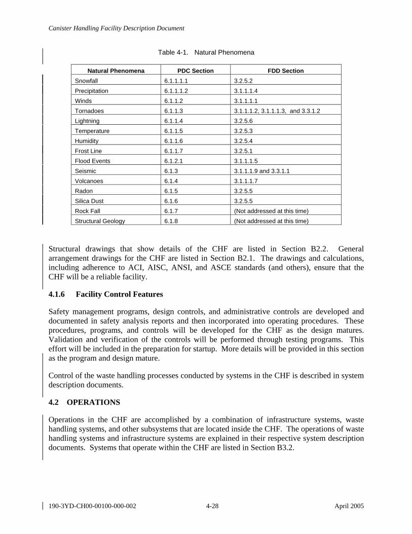
Canister Handling Facility Description Document
190-3YD-CH00-00100-000-002 4-28 April 2005
Table 4-1. Natural Phenomena
Natural Phenomena PDC Section FDD Section Snowfall 6.1.1.1.1 3.2.5.2 Precipitation 6.1.1.1.2 3.1.1.1.4 Winds 6.1.1.2 3.1.1.1.1 Tornadoes 6.1.1.3 3.1.1.1.2, 3.1.1.1.3, and 3.3.1.2 Lightning 6.1.1.4 3.2.5.6 Temperature 6.1.1.5 3.2.5.3 Humidity 6.1.1.6 3.2.5.4 Frost Line 6.1.1.7 3.2.5.1 Flood Events 6.1.2.1 3.1.1.1.5 Seismic 6.1.3 3.1.1.1.9 and 3.3.1.1 Volcanoes 6.1.4 3.1.1.1.7 Radon 6.1.5 3.2.5.5 Silica Dust 6.1.6 3.2.5.5 Rock Fall 6.1.7 (Not addressed at this time) Structural Geology 6.1.8 (Not addressed at this time)
Structural drawings that show details of the CHF are listed in Section B2.2. General arrangement drawings for the CHF are listed in Section B2.1. The drawings and calculations, including adherence to ACI, AISC, ANSI, and ASCE standards (and others), ensure that the CHF will be a reliable facility.
4.1.6 Facility Control Features
Safety management programs, design controls, and administrative controls are developed and documented in safety analysis reports and then incorporated into operating procedures. These procedures, programs, and controls will be developed for the CHF as the design matures. Validation and verification of the controls will be performed through testing programs. This effort will be included in the preparation for startup. More details will be provided in this section as the program and design mature.
Control of the waste handling processes conducted by systems in the CHF is described in system description documents.
4.2 OPERATIONS
Operations in the CHF are accomplished by a combination of infrastructure systems, waste handling systems, and other subsystems that are located inside the CHF. The operations of waste handling systems and infrastructure systems are explained in their respective system description documents. Systems that operate within the CHF are listed in Section B3.2.

Canister Handling Facility Description Document
190-3YD-CH00-00100-000-002 4-29 April 2005
4.2.1 Initial Configuration (Prestartup)
Prior to initiating waste handling operations, critical facility systems and subsystems are subjected to acceptance testing and verification. The initial configuration of the CHF is the same configuration as the final, though maintainable and replaceable components will be utilized to facilitate upgrades. The facility is designed to have an operational life of 50 years, as mandated by Section 3.1.1.3.4.
4.2.2 Facility Startup
This section will be completed following design completion. The section will summarize the key steps in starting up the facility systems including sequencing, timing, readiness for the next step, and determining success rate of startup. References to the governing procedures for facility startup will be included. At this time only general information is provided in this section. Details will be provided after design completion.
During initial facility startup, readiness reviews will be conducted to ensure that objective evidence exists that demonstrates satisfaction of work prerequisites; training and qualifying of personnel; availability of approved, detailed, implementing documents; and management controls.
4.2.3 Normal Operations
Contractors conduct routine facility inspections and related procedure compliance reviews; DOE or other external organizations conduct external reviews. These inspections are used during normal system operations to validate safety documentation, training, facility and equipment performance, and program implementation adequacy. System integration functions are verified through a readiness review process and are monitored and maintained during normal operations.
During normal operations, the individual system functions and systems integration will be monitored and maintained on a routine basis.
Primary facility functions are to provide structural protection to the systems, materials, and personnel within the facility. Walls, doors, and other barriers are provided and maintained to required codes and standards to provide adequate protection to systems, materials, and personnel within the facility under normal and off-normal operations. Facility maintenance and outages during normal operations are planned and scheduled, as needed, to conduct facility or system maintenance. Auxiliary or backup power will be supplied to maintain control equipment and critical functions during maintenance and outages. During normal operations, facility infrastructure and waste handling system functions are routinely monitored and maintained within acceptable thresholds. Safety controls, such as interlocks and criticality controls, will be established, monitored, and verified on a continuing basis during normal operations.
4.2.4 Off-Normal Operations
Off-normal operations are accommodated by the facility design. As noted above (Section 4.1.5), the facility is highly reliable and can withstand external phenomena. The facility design incorporates compartmentalization for the control of contamination, shielding to limit personnel
Canister Handling Facility Description Document
190-3YD-CH00-00100-000-002 4-30 April 2005
exposure, and a low leakage envelope for the canister transfer cell (Room 1033) to protect facility workers from event sequences. To accommodate facility evacuation that may be required during off-normal operations, egress paths are provided and designed to meet requirements as established in the PDC.
4.2.5 Facility Shutdown
Shutdown procedures, standby procedures, and monitoring procedures will be developed for systems operating in the CHF to support system shutdown.
4.2.6 Safety Management Programs and Administrative Controls
Integrated safety management system principles are required to provide a safe and controlled working environment for startup operations as well as normal and off-normal facility operations. Examples of safety management controls and principles include the following:
• Ensure adequate and correct procedures and work control documents for operating the systems are current, approved, and properly controlled
• Perform job safety analyses in accordance with procedures and controls to address hazards implementation into operating and maintenance procedures
• Complete health and safety walk-downs in the operating areas, as required, to support the activity and ensure deficiencies have been resolved
• Ensure that an adequate startup or restart program is in place to confirm the operability of equipment, viability of procedures and documents, and performance and knowledge of operators
• Perform successful dry runs, as required
• Confirm the formality and discipline of operations is adequate to conduct work safely and ensure that programs are in place to maintain this conduct of operations posture
• Ensure radiological work permits and associated personnel protective equipment is in place to support the activity
• Review environmental regulatory and permit requirements to ensure compliance for the activity
• Implement an integrated safety management system prior to startup and maintain the system through the life of the facility
• Establish a senior management review board.
Safety management programs and controls are developed and documented in documents, such as safety analysis reports, and they are incorporated into operations in the form of operating
Canister Handling Facility Description Document
190-3YD-CH00-00100-000-002 4-31 April 2005
procedures. These procedures, programs, and controls will be developed as the facility design matures and is finalized.
Safety management at the CHF is coordinated by the repository program environmental, safety and health organization, which implements the integrated safety management system. Requirements and descriptions for the safety management program are contained in Integrated Safety Management Description Document (Anderson 2003 [DIRS 170076]).
Administrative controls for the CHF have not been developed. Administration of the CHF includes local administration of the facility, administration of waste handling systems that are housed in the CHF, and coordination of the infrastructure systems. The repository administration, housed in the administration facility, coordinates site-wide operations at the repository.
4.2.6.1 Radiation Protection Programs
The CHF is designed to provide radiation protection to workers, the public, and the environment; achieve radiation doses ALARA in accordance with Section 3.2.1.1; and ensure that nuclear criticality events do not occur in the CHF. Control of radiological contamination within the CHF is required by Section 3.1.1.4.11. Shielded work areas, as required by Section 3.2.1.2, are incorporated into the design. The following documents have been prepared, reviewed, and approved, and demonstrate preliminary CHF compliance with radiation protection requirements. Additional work concerning radiation protection and nuclear criticality is expected during detailed design, construction, and operation of the CHF.
• ALARA Design Review Cover Sheet (Formal ALARA Design Review for the LA Design of the Canister Handling Facility and the Transportation Cask Receipt/Return Facility and Buffer Area) (BSC 2004 [DIRS 168895])
• Canister Handling Facility Criticality Safety Calculations (BSC 2005 [DIRS 173284])
• Canister Handling Facility Worker Dose Assessment (BSC 2004 [DIRS 167881])
• Shielding Calculation for Dry Transfer Facility, Remediation Facility, and Canister Handling Facility (BSC 2004 [DIRS 171405]).
4.3 TESTING AND MAINTENANCE
4.3.1 Temporary Configurations
Separate testing and maintenance programs and temporary configurations will be developed for systems operating in the CHF. At this stage of the design, no temporary configurations for facility testing or maintenance for the CHF are identified. When temporary configurations for testing or maintenance are necessary for the facility, they will be identified at that time.
Canister Handling Facility Description Document
190-3YD-CH00-00100-000-002 4-32 April 2005
4.3.2 Safety-Required Surveillances
When safety required surveillance requirements are determined, the design will accommodate those requirements. Specific requirements have not been identified (Section 3.4.2), therefore safety-required surveillances will be described in a future revision.
4.3.3 Non-Safety Inspections and Testing
Procedures will be developed to implement non-safety inspection and testing requirements after the requirements have been established (Section 3.4.3). The procedures will be based on the manufacturer’s recommendations and the final facility configuration.
4.3.4 Maintenance
Maintenance requirements for the CHF include the development of preventive maintenance and postmaintenance testing processes, and postmodification testing programs. The design process needs to progress further in order to identify maintenance requirements (Section 3.4.4) and a maintenance program for the CHF SSCs. The maintenance program for the CHF will be developed as part of the repository maintenance program.
The basic maintenance philosophy is to perform in situ maintenance whenever possible. The major equipment in the CHF consists of a 200-ton capacity cask handling crane, a 100-ton capacity waste package and canister handling crane, a waste package turntable, a trunnion collar removal machine, a waste package tilting machine, and waste package trolleys.
Crane maintenance rooms (Rooms 3006 and 3011) are provided at each end of the CHF for the cask handling crane and the waste package and canister handling crane, each with a 15-ton capacity maintenance crane. The 15-ton maintenance cranes are located above the roof over the cask handling crane and waste package and canister handling crane maintenance areas. The space provided in the CHF for the maintenance crane for the cask handling crane corresponds with the space developed on the drawing Canister Handling Facility Maint. Crane for Cask Crane Mechanical Equipment Envelope (Section B2.3). Space for the maintenance crane for the waste package and canister handling crane corresponds with the space developed on Canister Handling Facility Maintenance Crane for WP Crane Mechanical Equipment Envelope drawing (Section B2.3).
The maintenance rooms’ access is through roof hatches. Prior to performing required manual maintenance operations, radiation sources such as canisters, partially filled waste packages, and opened casks with canisters are shielded to allow personnel entry. The shield window stations are equipped with master/slave manipulators to disengage a failed grapple from the crane so that a new grapple can be remotely attached to the crane. After covering the radiation sources with shield plugs, personnel entry can be made to repair the grapple in place or bagout the equipment for repair elsewhere. Crane recovery features are provided to bring a failed crane into the crane maintenance area for repairs.
The waste package closure cell equipment is maintained in closure maintenance rooms (Rooms 3002 and 3008) located above the waste package closure cells. Each room is equipped with a
Canister Handling Facility Description Document
190-3YD-CH00-00100-000-002 4-33 April 2005
15-ton waste package closure maintenance crane. Closure equipment, such as power manipulators and cranes, can be moved into this maintenance room and repaired.
Canister Handling Facility Description Document
190-3YD-CH00-00100-000-002 4-34 April 2005
INTENTIONALLY LEFT BLANK
Canister Handling Facility Description Document
190-3YD-CH00-00100-000-002 5-1 April 2005
5. REFERENCES
5.1 DOCUMENTS CITED
150730 Bowman, F.L. and Itkin, I. 2000. Memorandum of Agreement for Acceptance of Naval Spent Nuclear Fuel. Memorandum of Agreement between the Director, Naval Nuclear Propulsion Program (NNPP), Department of the Navy, Arlington, VA and the Director, Office of Civilian Radioactive Waste Management (RW), U.S. Department of Energy (DOE), Washington, DC, Revision 1, April 11, 2000. ACC: HQP.20000628.0006.
158398 DOE (U.S. Department of Energy) 2002. U.S. Department of Energy Spent Nuclear Fuel and High-Level Radioactive Waste to the Monitored Geologic Repository. Volume 1 of Integrated Interface Control Document. DOE/RW-0511 Rev. 01. Las Vegas, Nevada: U.S. Department of Energy. ACC: MOL.20020614.0342.
160757 BNFL Fuel Solutions 2002. FuelSolutions™ TS125 Transportation Cask Safety Analysis Report, Revision 3. WSNF-120. Docket No. 71-9276. Scotts Valley, California: BNFL Fuel Solutions. TIC: 254026.
162546 NRC (U.S. Nuclear Regulatory Commission) 2002. Certificate of Compliance for Radioactive Material Packages, BNFL Fuel Solutions, Application Dated April 20, 2001, as Supplemented. Certification No. 9276, Rev. 0. Washington, D.C.: U.S. Nuclear Regulatory Commission. ACC: MOL.20030411.0228.
162547 NRC (U.S. Nuclear Regulatory Commission) 2002. Certificate of Compliance for Radioactive Material Packages, NAC International, Inc., Application Dated April 30, 1997, as Supplemented. Certificate No. 9270, Rev. 0. Washington, D.C.: U.S. Nuclear Regulatory Commission. ACC: MOL.20030411.0227.
164612 NAC International 2002. Safety Analysis Report for the UMS® Universal Transport Cask. UMST-02E. EA790-SAR-001. Docket No. 71-9270. Volume 1. Norcross, Georgia: NAC International. TIC: 254855.
165219 McKenzie, J.M. 2002. Naval Nuclear Propulsion Program Technical Baseline Compliance Document, Revision 1, October 2002. Letter from J.M. McKenzie (DOE) to J. Williams (DOE/OCRWM), November 19, 2002, NR:RA:RWIshihara U#02-2852, with enclosure. ACC: HQO.20030502.0028; HQO.20030502.0029.
166275 Canori, G.F. and Leitner, M.M. 2003. Project Requirements Document. TER-MGR-MD-000001 REV 02. Las Vegas, Nevada: Bechtel SAIC Company. ACC: DOC.20031222.0006.
167176 BSC (Bechtel SAIC Company) 2003. CHF Electrical Installation Space Requirement Calculation. 190-E0C-E000-00100-000-00A. Las Vegas, Nevada: Bechtel SAIC Company. ACC: ENG.20031211.0001.
Canister Handling Facility Description Document
190-3YD-CH00-00100-000-002 5-2 April 2005
167313 BSC (Bechtel SAIC Company) 2004. Preliminary Hazards Analysis for License Application Study. 000-30R-HPYK-00100-000-00A. Las Vegas, Nevada: Bechtel SAIC Company. ACC: ENG.20040610.0002.
167881 BSC (Bechtel SAIC Company) 2004. Canister Handling Facility Worker Dose Assessment. 190-00C-CH00-00200-000-00A. Las Vegas, Nevada: Bechtel SAIC Company. ACC: ENG.20040303.0051.
168814 BSC (Bechtel SAIC Company) 2005. Canister Handling Facility Fire Hazard Analysis. 190-30R-PF00-00100-000-00A. Las Vegas, Nevada: Bechtel SAIC Company. ACC: ENG.20050311.0001.
168875 BSC (Bechtel SAIC Company) 2004. Canister Handling Facility Second Closure Cell. Baseline Change Proposal BCP-YMP-2004-070. Las Vegas, Nevada: Bechtel SAIC Company. ACC: MOV.20040622.0012.
168895 BSC (Bechtel SAIC Company) 2004. ALARA Design Review Cover Sheet (Formal ALARA Design Review for the LA Design of the Canister Handling Facility and the Transportation Cask Receipt/Return Facility and Buffer Area). ALARA Design Review No.: AP-04-001, January 13, 2004. 190-30V-HPRA-00100-000-00A. Las Vegas, Nevada: Bechtel SAIC Company. ACC: MOL.20040202.0081.
169064 Cogema 2004. Navy Event Drop Heights. COGEMA-C0115-EN-CLC-0001, Rev. 3. Las Vegas, Nevada: Cogema. ACC: ENG.20040422.0040.
169235 Gutherman, B. 2003. “USNRC Docket No. 71-9261, HI-STAR 100 Certificate of Compliance 9261, Submittal of HI-STAR 100 Safety Analysis Report, Revision 10.” Letter from B. Gutherman (Holtec) to U.S. Nuclear Regulatory Commission, August 21, 2003, with enclosures. TIC: 255249.
169271 BSC (Bechtel SAIC Company) 2004. Mechanical Equipment Envelope Calculation for Surveying and Removal of Radiological Contamination from External Surfaces of Waste Packages System. 100-M0C-MR00-00200-000-00A. Las Vegas, Nevada: Bechtel SAIC Company. ACC: ENG.20040522.0008.
169272 BSC (Bechtel SAIC Company) 2004. Mechanical Equipment Envelope Calculation for Cask Cavity Gas Sampling System. 100-M0C-MRE0-00200-000-00A. Las Vegas, Nevada: Bechtel SAIC Company. ACC: ENG.20040609.0007.
169273 BSC (Bechtel SAIC Company) 2004. Mechanical Equipment Envelope Calculation for Cask and Waste Package Inerting System. 100-M0C-MRI0-00200-000-00A. Las Vegas, Nevada: Bechtel SAIC Company. ACC: ENG.20040610.0001.
169362 Thompson, T.C. 2003. “NAC-STC Safety Analysis Report, Revision 14.” Letter from T.C. Thompson (NAC International) to the NRC, June 18, 2003, with enclosures. TIC: 255255.
Canister Handling Facility Description Document
190-3YD-CH00-00100-000-002 5-3 April 2005
169464 BSC (Bechtel SAIC Company) 2004. Hydrologic Engineering Studies for the North Portal Pad and Vicinity. 000-00C-CD04-00100-000-00A. Las Vegas, Nevada: Bechtel SAIC Company. ACC: ENG.20040504.0005.
169498 BSC (Bechtel SAIC Company) 2004. Evaluation for Tornado Effects. 110-S0C-CD00-00100-000-00C. Las Vegas, Nevada: Bechtel SAIC Company. ACC: ENG.20040617.0013.
169512 BSC (Bechtel SAIC Company) 2004. Mechanical Equipment Envelope Calculation for LLW Liquid Collection System. 100-M0C-MRL0-00200-000-00A. Las Vegas, Nevada: Bechtel SAIC Company. ACC: ENG.20040609.0008.
170076 Anderson, W.F. 2003. Integrated Safety Management Description Document. PGM-CRW-AD-000001 Rev 03. Las Vegas, Nevada: Bechtel SAIC Company. ACC: DOC.20040316.0003.
170557 Curry, P.M. 2004. Project Functional and Operational Requirements. TDR-MGR-ME-000003 REV 02. Las Vegas, Nevada: Bechtel SAIC Company. ACC: DOC.20040714.0003.
171018 BSC (Bechtel SAIC Company) 2004. CHF Local Control and Support Areas Space Requirements Calculation. 190-JDC-OSS0-00100-000-00B. Las Vegas, Nevada: Bechtel SAIC Company. ACC: ENG.20040729.0001.
171034 BSC (Bechtel SAIC Company) 2004. Canister Handling Facility Communications Equipment Space Requirements Calculation. 190-EFC-EC00-00100-000-00B. Las Vegas, Nevada: Bechtel SAIC Company. ACC: ENG.20040803.0001.
171190 BSC (Bechtel SAIC Company) 2005. Q-List. 000-30R-MGR0-00500-000-001. Las Vegas, Nevada: Bechtel SAIC Company. ACC: ENG.20050217.0010
171405 BSC (Bechtel SAIC Company) 2004. Shielding Calculation for Dry Transfer Facility, Remediation Facility, and Canister Handling Facility. 100-00C-WHS0-00200-000-00B. Las Vegas, Nevada: Bechtel SAIC Company. ACC: ENG.20040830.0030.
171501 BSC (Bechtel SAIC Company) 2004. Repository Design Requirements: Safeguards and Security. TER-MGR-AD-000002 REV 00. Las Vegas, Nevada: Bechtel SAIC Company. ACC: DOC.20040805.0002.
171512 BSC (Bechtel SAIC Company) 2005. Nuclear Safety Design Bases for License Application. 000-30R-MGR0-00400-000-001. Las Vegas, Nevada: Bechtel SAIC Company. ACC: ENG.20050308.0004.
171539 DOE (U.S. Department of Energy) 2004. Quality Assurance Requirements and Description. DOE/RW-0333P, Rev. 16. Washington, D.C.: U.S. Department of Energy, Office of Civilian Radioactive Waste Management. ACC: DOC.20040907.0002.
Canister Handling Facility Description Document
190-3YD-CH00-00100-000-002 5-4 April 2005
171546 Thompson, T.C. 2000. "Docket No. 72-1025, Submittal of NAC-MPC FSAR, Revision 0 (TAC No. L22907)." Letter from T.C. Thompson (NAC) to the NRC, May 23, 2000, with enclosure. TIC: 255236.
171599 BSC (Bechtel SAIC Company) 2004. Project Design Criteria Document. 000-3DR-MGR0-00100-000-003. Las Vegas, Nevada: Bechtel SAIC Company. ACC: ENG.20041124.0001.
172003 BSC (Bechtel SAIC Company) 2004. Soil Spring Values Using ASCE 4-98 Approach for CHF with Two Closure Cells. 190-SYC-SY00-00800-000-00B. Las Vegas, Nevada: Bechtel SAIC Company. ACC: ENG.20041011.0002.
172085 BSC (Bechtel SAIC Company) 2004. Seismic Analysis Using Multiple Stick Model of CHF with Two Closure Cells. 190-SYC-SY00-00900-000-00B. Las Vegas, Nevada: Bechtel SAIC Company. ACC: ENG.20041101.0004.
172373 DOE (U.S. Department of Energy) 2004. Preclosure Seismic Design Methodology for a Geologic Repository at Yucca Mountain. Topical Report YMP/TR-003-NP, Rev. 3. Las Vegas, Nevada: U.S. Department of Energy, Office of Repository Development. ACC: MOL.20041103.0002.
172509 BSC (Bechtel SAIC Company) 2005. Concrete Design Calculations for CHF with Two Closure Cells. 190-DBC-DB00-00700-000-00B. Las Vegas, Nevada: Bechtel SAIC Company. ACC: ENG.20050107.0001.
172510 BSC (Bechtel SAIC Company) 2004. Structural Steel Design Calculations for CHF with Two Closure Cells. 190-SSC-SS00-00400-000-00B. Las Vegas, Nevada: Bechtel SAIC Company. ACC: ENG.20041220.0062.
172511 BSC (Bechtel SAIC Company) 2004. Foundation Calculation for CHF with Two Closure Cells. 190-SYC-SY00-00700-000-00B. Las Vegas, Nevada: Bechtel SAIC Company. ACC: ENG.20041220.0065.
173132 Cogema 2005. Canister Handling Facility Mechanical Handling Equipment List. COGEMA-C0115-EN-EL-005, Rev. F. Las Vegas, Nevada: Cogema. ACC: ENG.20050210.0005.
173284 BSC (Bechtel SAIC Company) 2005. Canister Handling Facility Criticality Safety Calculations. 190-00C-CH00-00100-000-00B. Las Vegas, Nevada: Bechtel SAIC Company. ACC: ENG.20050411.0001.
5.2 CODES, STANDARDS, REGULATIONS, AND PROCEDURES
104026 64 FR 30851. Greening the Government Through Efficient Energy Management. Executive Order 13123. Readily available.
105990 Regulatory Guide 1.86, Rev. 0. 1974. Termination of Operating Licenses for Nuclear Reactors. Washington, D.C.: U.S. Nuclear Regulatory Commission. TIC: 218739.
Canister Handling Facility Description Document
190-3YD-CH00-00100-000-002 5-5 April 2005
158833 ACI 349-01. 2001. Code Requirements for Nuclear Safety Related Concrete Structures (ACI 349-01). Farmington Hills, Michigan: American Concrete Institute. TIC: 252732.
158835 ANSI/AISC N690-1994. 1994. American National Standard Specification for the Design, Fabrication, and Erection of Steel Safety-Related Structures for Nuclear Facilities. Chicago, Illinois: American Institute of Steel Construction. TIC: 252734.
158854 NFPA 780. 2001. Standard for the Installation of Lightning Protection Systems. 2000 Edition. Quincy, Massachusetts: National Fire Protection Agency. TIC: 252748.
158913 DOE O 430.2A. 2002. Departmental Energy and Utilities Management. Washington, D.C.: U.S. Department of Energy. Readily available.
160921 NFPA 13. 2002. Standard for the Installation of Sprinkler Systems. 2002 Edition. Quincy, Massachusetts: National Fire Protection Association. TIC: 253657.
160954 NFPA 72. 2002. National Fire Alarm Code. 2002 Edition. Quincy, Massachusetts: National Fire Protection Association. TIC: 253686.
161567 DOE O 450.1. 2003. Environmental Protection Program. Washington, D.C.: U.S. Department of Energy. Readily available.
165077 NFPA 801. 2003. Standard for Fire Protection for Facilities Handling Radioactive Materials. 2003 Edition. Quincy, Massachusetts: National Fire Protection Association. TIC: 254811.
173273 10 CFR 63. 2005 Energy: Disposal of High-Level Radioactive Wastes in a Geologic Repository at Yucca Mountain, Nevada. ACC: MOL.20050405.0118.
173279 49 CFR 173. 2004 Transportation: Shippers - General Requirements for Shipments and Packagings. ACC: MOL.20050405.0318.
5.3 DATA TRACKING NUMBERS
This document does not utilize data tracking numbers from the technical data management system.
5.4 SOFTWARE CODES
This document does not use software that is subject to the control of the software configuration management organization.
Canister Handling Facility Description Document
190-3YD-CH00-00100-000-002 5-6 April 2005
INTENTIONALLY LEFT BLANK
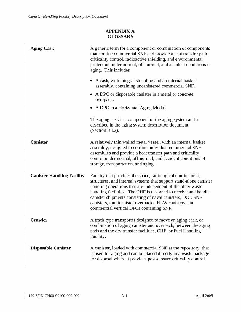
Canister Handling Facility Description Document
190-3YD-CH00-00100-000-002 A-1 April 2005
APPENDIX A GLOSSARY
Aging Cask A generic term for a component or combination of components that confine commercial SNF and provide a heat transfer path, criticality control, radioactive shielding, and environmental protection under normal, off-normal, and accident conditions of aging. This includes
• A cask, with integral shielding and an internal basket assembly, containing uncanistered commercial SNF.
• A DPC or disposable canister in a metal or concrete overpack.
• A DPC in a Horizontal Aging Module.
The aging cask is a component of the aging system and is described in the aging system description document (Section B3.2).
Canister A relatively thin walled metal vessel, with an internal basket assembly, designed to confine individual commercial SNF assemblies and provide a heat transfer path and criticality control under normal, off-normal, and accident conditions of storage, transportation, and aging.
Canister Handling Facility Facility that provides the space, radiological confinement, structures, and internal systems that support stand-alone canister handling operations that are independent of the other waste handling facilities. The CHF is designed to receive and handle canister shipments consisting of naval canisters, DOE SNF canisters, multicanister overpacks, HLW canisters, and commercial vertical DPCs containing SNF.
Crawler A track type transporter designed to move an aging cask, or combination of aging canister and overpack, between the aging pads and the dry transfer facilities, CHF, or Fuel Handling Facility.
Disposable Canister A canister, loaded with commercial SNF at the repository, that is used for aging and can be placed directly in a waste package for disposal where it provides post-closure criticality control.
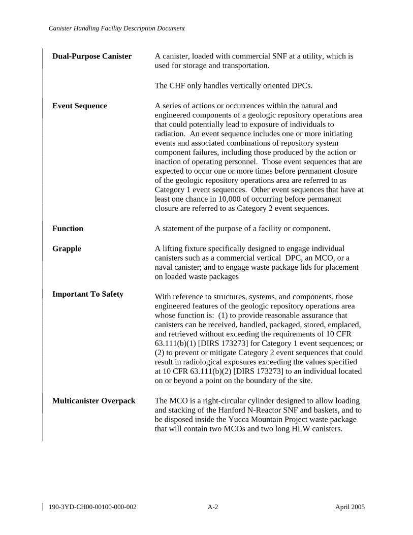
Canister Handling Facility Description Document
190-3YD-CH00-00100-000-002 A-2 April 2005
Dual-Purpose Canister A canister, loaded with commercial SNF at a utility, which is used for storage and transportation.
The CHF only handles vertically oriented DPCs.
Event Sequence A series of actions or occurrences within the natural and engineered components of a geologic repository operations area that could potentially lead to exposure of individuals to radiation. An event sequence includes one or more initiating events and associated combinations of repository system component failures, including those produced by the action or inaction of operating personnel. Those event sequences that are expected to occur one or more times before permanent closure of the geologic repository operations area are referred to as Category 1 event sequences. Other event sequences that have at least one chance in 10,000 of occurring before permanent closure are referred to as Category 2 event sequences.
Function A statement of the purpose of a facility or component.
Grapple A lifting fixture specifically designed to engage individual canisters such as a commercial vertical DPC, an MCO, or a naval canister; and to engage waste package lids for placement on loaded waste packages
Important To Safety With reference to structures, systems, and components, those engineered features of the geologic repository operations area whose function is: (1) to provide reasonable assurance that canisters can be received, handled, packaged, stored, emplaced, and retrieved without exceeding the requirements of 10 CFR 63.111(b)(1) [DIRS 173273] for Category 1 event sequences; or (2) to prevent or mitigate Category 2 event sequences that could result in radiological exposures exceeding the values specified at 10 CFR 63.111(b)(2) [DIRS 173273] to an individual located on or beyond a point on the boundary of the site.
Multicanister Overpack The MCO is a right-circular cylinder designed to allow loading and stacking of the Hanford N-Reactor SNF and baskets, and to be disposed inside the Yucca Mountain Project waste package that will contain two MCOs and two long HLW canisters.
Canister Handling Facility Description Document
190-3YD-CH00-00100-000-002 A-3 April 2005
Multipurpose Canister Refers to a sealed, metallic container maintaining multiple SNF assemblies in a dry, inert environment and overpacked separately and uniquely for the various system elements of storage, transportation, and disposal. See also the definition of waste form.
Off-Normal An occurrence of an event or condition that is outside the bounds of routine operations, but within the range of analyzed conditions for the SSC.
Overpack A relatively thick walled metal or concrete vessel designed to enclose canistered commercial SNF in a vertical orientation and provide a heat transfer path, radioactive shielding, and environmental protection under normal, off-normal, and accident conditions of storage and/or aging. See “multicanister overpack” for a separate definition of MCO.
Performance Acceptance Criteria
Statements that provide verifiable measures of how well the design specification has been achieved or limits against which the actual performance capability of the as-built system can be evaluated.
Preclosure Safety Analysis Systematic examination of the site, design, potential hazards, initiating events, event sequences, and consequences that include radiological exposures to workers and the public. The analysis identifies SSCs that are ITS.
Requirement A specification of what the design solution must do. Requirement statements include a statement of how well the specification is to be achieved to permit verification. In some cases, there are several criteria for measuring the success of the achievement of the specification and these are listed as performance acceptance criteria.
Requirement Category Requirement categories specify the primary category to which a requirement belongs. A detailed description of requirement categories is provided in the Design Requirements Classification section in LP-3.26Q-BSC, System Description Documents. The four categories are 10 CFR Part 63 [DIRS 173273], licensing, external compliance, and engineering requirements.
10 CFR Part 63 [DIRS 173273]:
The subset of the design requirements and design bases that are used and credited within the safety analysis to document the safety case for SSCs that are ITS or important to waste isolation.
Canister Handling Facility Description Document
190-3YD-CH00-00100-000-002 A-4 April 2005
Licensing Requirements: Those requirements associated with SSCs for which commitments are made as part of the License Application as an integral part of the licensing process, but which are not credited to document the safety case for ITS SSCs or SSCs that are important to waste isolation.
External Compliance: This subset of design requirements and design bases will include the requirements imposed on the project through applicable codes, laws, statutes, or regulations (excluding U.S. Nuclear Regulatory Commission regulations) for SSCs supporting environmental and regulatory impact-oriented functions and worker protection.
Engineering Requirements:
The balance of requirements and bases included here will affect some part of the design and operation of the repository; they form the technical baseline for business needs but are not addressed as part of the other three design requirements classification.
Site Rail Transfer Cart The conveyance used to move transportation casks, aging casks, and waste packages between the TCRRF, the CHF, and the Dry Transfer Facilities. The cart travels on rail and is moved by the SRTC tractor in and out of each facility, and on and off the SRTC positioner. The SRTC is designed to accommodate incoming transportation casks, aging casks, and waste packages using interchangeable adapters, skids, or attachment devices designed specifically for each type of cask, skid, or waste package.
Transportation Cask A cask, with impact limiters and personnel barriers, used for transporting SNF and HLW on the nation’s highways and railroads.
• It is used, without an internal basket assembly, to transport DPCs and provide a heat transfer path, handling, shielding, and environmental protection under normal, off-normal, and accident conditions during transport.
• It is used, with an internal basket assembly, to confine and transport uncanistered SNF and provide a heat transfer path, criticality control, radioactive shielding, and environmental protection under normal, off-normal, and accident conditions during transport.
Canister Handling Facility Description Document
190-3YD-CH00-00100-000-002 A-5 April 2005
Waste Form Radioactive waste material and any encapsulating or stabilizing matrix.
Yoke A lifting device designed to handle transportation casks, aging casks, waste packages, or waste package pallets. Yokes are attached manually to shielded transportation casks, shielded aging casks, unloaded waste packages, and unloaded waste package pallets. Yokes are attached remotely to engage loaded waste packages, and loaded waste package and emplacement pallet combinations.

Canister Handling Facility Description Document
190-3YD-CH00-00100-000-002 A-6 April 2005
INTENTIONALLY LEFT BLANK

Canister Handling Facility Description Document
190-3YD-CH00-00100-000-002 B-1 April 2005
APPENDIX B KEY FACILITY CHARTS, DIAGRAMS, DRAWINGS, AND LISTS
B1 FIGURES
The following figures are included within this FDD:
Figure B-1. Canister Handling Facility Ground Floor Plan
Figure B-1 is based on the drawings Canister Handling Facility General Arrangement Pit & Mezzanine Floor Plans and Canister Handling Facility General Arrangement Ground Floor Plan (Section B2.1).
Figure B-2. Canister Handling Facility Second Floor Plan
Figure B-2 is based on the drawing Canister Handling Facility General Arrangement Second Floor Plan (Section B2.1).
Figure B-3. Canister Handling Facility Third Floor Plan
Figure B-3 is based on the drawing Canister Handling Facility General Arrangement Third Floor Plan (Section B2.1).
Figure B-4. Canister Handling Facility Sections
Figure B-4 is based on Canister Handling Facility General Arrangement Section A & B, and Canister Handling Facility General Arrangement Section H & J (Section B2.1).
Figure B-5. Maximum Canister Inventory of SNF and HLW in the Canister Handling Facility
This figure was developed to illustrate the maximum inventory of SNF and HLW that could be present in the CHF.
Figure B-6. Canister Handling Facility Operations Block Flow Diagram
This figure was developed to illustrate system and facility interfaces that handle casks, waste packages, and other components.
Figure B-7. Material Flow Path Diagram
This figure was developed to illustrate how materials are handled in the CHF.
Figure B-8. Waste Package Drop Mitigation
This figure was developed to illustrate a concept for mitigation of waste package drops. The features illustrated in the figure are subject to further analysis.
Canister Handling Facility Description Document
190-3YD-CH00-00100-000-002 B-2 April 2005
Figure B-9. Naval Cask Lifting Arrangement
Figure B-9 is modified from Navy Event Drop Heights (Cogema 2004 [DIRS 169064], Section 1.3).
B2 DRAWINGS
The following drawings provide additional details of the CHF. The current approved version of each drawing is available in the Controlled Documents Information System.
B2.1 CHF GENERAL ARRANGEMENT DRAWINGS
Canister Handling Facility General Arrangement Legend and General Notes
190-P10-CH00-00101-000
Canister Handling Facility General Arrangement Key Plan 190-P10-CH00-00102-000
Canister Handling Facility General Arrangement Ground Floor Plan
190-P10-CH00-00103-000
Canister Handling Facility General Arrangement Pit & Mezzanine Floor Plans
190-P10-CH00-00104-000
Canister Handling Facility General Arrangement Second Floor Plan
190-P10-CH00-00105-000
Canister Handling Facility General Arrangement Third Floor Plan 190-P10-CH00-00106-000
Canister Handling Facility General Arrangement Roof Plan 190-P10-CH00-00107-000
Canister Handling Facility General Arrangement Section A & B 190-P10-CH00-00108-000
Canister Handling Facility General Arrangement Section C & D 190-P10-CH00-00109-000
Canister Handling Facility General Arrangement Section E 190-P10-CH00-00110-000
Canister Handling Facility General Arrangement Section F & G 190-P10-CH00-00111-000
Canister Handling Facility General Arrangement Section H & J 190-P10-CH00-00112-000
Canister Handling Facility General Arrangement Section K & L 190-P10-CH00-00113-000
Canister Handling Facility Description Document
190-3YD-CH00-00100-000-002 B-3 April 2005
B2.2 CHF STRUCTURAL DRAWINGS
Canister Handling Facility Structural General Notes and Reference Drawings
190-S00-CH00-00101-000
Canister Handling Facility Structural Floor Plan at Elevation +0’ – 0”
190-S00-CH00-00201-000
Canister Handling Facility Structural Floor Plan at Elevation +32’ – 0”
190-S00-CH00-00301-000
Canister Handling Facility Structural Floor Plan at Elevation +64’ – 0”
190-S00-CH00-00401-000
Canister Handling Facility Closure & Crane Maint. Rooms Column Pedestal Plans at Elevation +65’ – 0”
190-S00-CH00-00501-000
Canister Handling Facility Structural Floor Plans at Elevations +16’ – 0” & +27’ – 0”
190-S00-CH00-00601-000
Canister Handling Facility Exit and Entrance Vestibules Structural Framing Plans and Sections
190-S00-CH00-00701-000
Canister Handling Facility Closure Maintenance Room Structural Framing Plans and Sections
190-S00-CH00-00801-000
Canister Handling Facility Crane Maintenance Room Structural Framing Plans and Sections
190-S00-CH00-00901-000
Canister Handling Facility Structural Longitudinal Sections AA and BB
190-S00-CH00-01001-000
Canister Handling Facility Structural Longitudinal Sections CC and DD
190-S00-CH00-01101-000
Canister Handling Facility Structural Cross Sections EE and FF 190-S00-CH00-01201-000
Canister Handling Facility Structural Cross Sections GG and HH 190-S00-CH00-01301-000
Canister Handling Facility Structural Cross Section JJ 190-S00-CH00-01401-000
Canister Handling Facility Top Reinforcing Bars Foundation Mat at El +0’ – 0”
190-S00-CH00-01501-000
Canister Handling Facility Bottom Reinforcing Bars Foundation Mat at El +0’ – 0”
190-S00-CH00-01601-000
Canister Handling Facility Description Document
190-3YD-CH00-00100-000-002 B-4 April 2005
Canister Handling Facility Wall Reinforcing Bars Structural Sections
190-S00-CH00-01701-000
Canister Handling Facility Miscellaneous Structural Sections and Details
190-S00-CH00-01801-000
B2.3 MECHANICAL EQUIPMENT ENVELOPE DRAWINGS
Cask Receipt and Return System Site Rail Transfer Cart (SRTC) Mechanical Equipment Envelope
V0-M00Z-QPA0-05391-00119
Cask Receipt and Return System SRTC Tractor Mechanical Equipment Envelope
V0-M00Z-QPA0-05391-00191.
Canister Handling Facility Entrance Vestibule Crane Mechanical Equipment Envelope
V0-M00Z-QPA0-05391-00124.
Canister Handling Facility Elevating and Mobile Platform Mechanical Equipment Envelope
V0-M00Z-QPA0-05391-00135
Canister Handling Facility Cask Handling Crane Mechanical Equipment Envelope
V0-M00Z-QPA0-05391-00125
Canister Handling Facility WP and Canister Handling Crane Mechanical Equipment Envelope
V0-M00Z-QPA0-05391-00126
Canister Handling Facility WP Tilting Machine Mechanical Equipment Envelope
V0-M00Z-QPA0-05391-00127
Canister Handling Facility WP Turntable Mechanical Equipment Envelope
V0-M00Z-QPA0-05391-00128
Canister Handling Facility Collar Removal Machine Mechanical Equipment Envelope
V0-M00Z-QPA0-05391-00129
Canister Handling Facility WP Trolley Mechanical Equipment Envelope.
V0-M00Z-QPA0-05391-00130
Canister Handling Facility WP/Pallet Lifting Yoke Mechanical Equipment Envelope
V0-M00Z-QPA0-05391-00136
Canister Handling Facility Maint. Crane for Cask Crane Mechanical Equipment Envelope
V0-M00Z-QPA0-05391-00131
Canister Handling Facility Maintenance Crane for WP Crane Mechanical Equipment Envelope
V0-M00Z-QPA0-05391-00132
Canister Handling Facility Description Document
190-3YD-CH00-00100-000-002 B-5 April 2005
Canister Handling Facility Cask Lifting Yoke Mechanical Equipment Envelope.
V0-M00Z-QPA0-05391-00133
Canister Handling Facility WP Lifting Yoke Mechanical Equipment Envelope
V0-M00Z-QPA0-05391-00122
Canister Handling Facility Manipulator Work Station Mechanical Equipment Envelope
V0-M00Z-QPA0-05391-00188
SNF Aging System MSC Transporter Mechanical Equipment Envelope
170-MQ0-HAT0-00401-000
Canister Handling Facility Closure Support Crane Mechanical Equipment Envelope
190-MJ0-HWH0-00101-000
Canister Handling Facility Closure Maintenance Crane Mechanical Equipment Envelope
190-MJ0-HWH0-00201-000
Yucca Mountain Canister Handling Facility WP Closure Cell Crane (15 ton) Mechanical Equipment Envelope
005128Q-0010-001
Yucca Mountain Canister Handling Facility WP Closure Cell Remote Handling Crane (3 ton) Mechanical Equipment Envelope
005128Q-0013-001
B2.4 MISCELLANEOUS DRAWINGS
Emplacement and Retrieval General Arrangement Locomotive
800-MQ0-HES0-00201-000
Emplacement and Retrieval General Arrangement Waste Package Transporter
800-MQ0-HET0-00101-000
Geologic Repository Operations Area Flood Drainage System Site Layout
100-C00-MGR0-00301-000
Geologic Repository Operations Area North Portal Site Plan 100-C00-MGR0-00101-000
Monitored Geologic Repository, Repository Systems Architecture Legend Systems Legend
000-B00-MGR0-00101-000
Waste Package Envelope Dimensions for Facilities & Handling
000-B20-MGR0-00101-000
Waste Package Envelope Dimensions for Facilities & Handling
000-B20-MGR0-00102-000
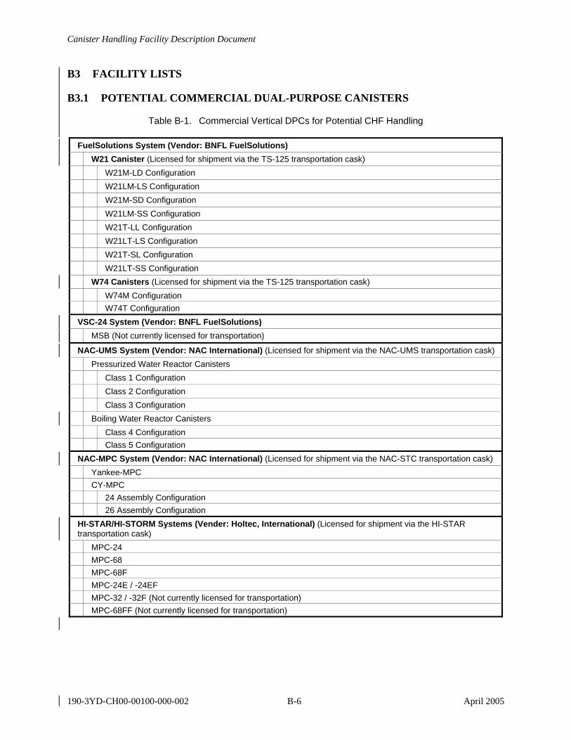
Canister Handling Facility Description Document
190-3YD-CH00-00100-000-002 B-6 April 2005
B3 FACILITY LISTS
B3.1 POTENTIAL COMMERCIAL DUAL-PURPOSE CANISTERS
Table B-1. Commercial Vertical DPCs for Potential CHF Handling
FuelSolutions System (Vendor: BNFL FuelSolutions) W21 Canister (Licensed for shipment via the TS-125 transportation cask) W21M-LD Configuration W21LM-LS Configuration W21M-SD Configuration W21LM-SS Configuration W21T-LL Configuration W21LT-LS Configuration W21T-SL Configuration W21LT-SS Configuration W74 Canisters (Licensed for shipment via the TS-125 transportation cask) W74M Configuration W74T Configuration VSC-24 System (Vendor: BNFL FuelSolutions) MSB (Not currently licensed for transportation)
NAC-UMS System (Vendor: NAC International) (Licensed for shipment via the NAC-UMS transportation cask) Pressurized Water Reactor Canisters Class 1 Configuration Class 2 Configuration Class 3 Configuration Boiling Water Reactor Canisters Class 4 Configuration Class 5 Configuration NAC-MPC System (Vendor: NAC International) (Licensed for shipment via the NAC-STC transportation cask) Yankee-MPC CY-MPC 24 Assembly Configuration 26 Assembly Configuration HI-STAR/HI-STORM Systems (Vender: Holtec, International) (Licensed for shipment via the HI-STAR transportation cask) MPC-24 MPC-68 MPC-68F MPC-24E / -24EF MPC-32 / -32F (Not currently licensed for transportation) MPC-68FF (Not currently licensed for transportation)
Canister Handling Facility Description Document
190-3YD-CH00-00100-000-002 B-7 April 2005
B3.2 SYSTEM AND FACILITY DESCRIPTION DOCUMENTS
The following systems and facilities interface with the CHF. Current approved versions of the facility and system description documents are available in the Controlled Documents Information System.
Balance of Plant Facility Description Document 600-3YD-SB00-00100-000
Cask Receipt and Return System Description Document 140-3YD-HC00-00100-000
Cask/MSC/WP Preparation System Description Document 110-3YD-HM00-00100-000
Communications System Description Document 000-3YD-EC00-00100-000
Digital Control and Management Information System Description Document
000-3YD-JD00-00100-000
DOE and Commercial Waste Package System Description Document
000-3YD-DS00-00100-000
Electrical Power System Description Document 000-3YD-EE00-00200-000
Electrical Support System Description Document 000-3YD-EU00-00100-000
Emplacement and Retrieval System Description Document 800-3YD-HE00-00100-000
Environmental/Meteorological Monitoring System Description Document
000-3YD-JE00-00100-000
Fire Protection System Description Document 000-3YD-PF00-00100-000
HVAC Plant Heating and Cooling System Description Document 100-3YD-VP00-00100-000
Low-Level Radioactive Waste Generating System Description Document
100-3YD-MR00-00200-000
Low-Level Radioactive Waste Management System Description Document
100-3YD-MR00-00100-000
Naval Spent Nuclear Fuel Waste Package System Description Document
000-3YD-DN00-00100-000
Non-Nuclear Handling System Description Document 150-3YD-HN00-00100-000
Non-Radiological Waste Management System Description Document
100-3YD-MN00-00100-000
Plant Services System Description Document 100-3YD-PS00-00100-000

Canister Handling Facility Description Document
190-3YD-CH00-00100-000-002 B-8 April 2005
Radiation/Radiological Monitoring System Description Document
000-3YD-JR00-00100-000
Remediation System Description Document 130-3YD-HR00-00100-000
Safeguards and Security System Description Document 000-3YD-ES00-00200-000
SNF Aging System Description Document 170-3YD-HA00-00100-000
SNF/HLW Transfer System Description Document 110-3YD-HT00-00100-000
Surface Industrial HVAC System Description Document 000-3YD-VI00-00100-000
Surface Nuclear HVAC System Description Document 000-3YD-VN00-00100-000
Waste Package Closure System Description Document 100-3YD-HW00-00100-000
B4 WASTE HANDLING SYSTEM SPACE DESCRIPTIONS
B4.1 CASK RECEIPT AND RETURN SYSTEM
The facility provides space in the entrance vestibule (Room 1036) and canister transfer cell (Room 1033) to park an SRTC and SRTC tractor, LWT, or OWT. The provided space for the SRTC is as shown on Cask Receipt and Return System Site Rail Transfer Cart (SRTC) Mechanical Equipment Envelope (Section B2.3) drawing. The provided space for the SRTC tractor is as shown on Cask Receipt and Return System SRTC Tractor Mechanical Equipment Envelope (Section B2.3) drawing. The provided space for an LWT or OWT is consistent with the space shown in U.S. Department of Energy Spent Nuclear Fuel and High-Level Radioactive Waste to the Monitored Geologic Repository, Volume 1 of Integrated Interface Control Document (DOE 2002 [DIRS 158398], Figure B-1).
The facility provides space in the entrance vestibule (Room 1036) to stage DOE transportation cask impact limiters. The impact limiters associated with the largest DOE transportation cask are documented in U.S. Department of Energy Spent Nuclear Fuel and High-Level Radioactive Waste to the Monitored Geologic Repository Volume 1 of Integrated Interface Control Document (DOE 2002 [DIRS 158398], Figure B-4). Space is sufficient to accommodate naval cask impact limiters. The impact limiters associated with the naval cask is documented in U.S. Department of Energy Spent Nuclear Fuel and High-Level Radioactive Waste to the Monitored Geologic Repository Volume 1 of Integrated Interface Control Document (DOE 2002 [DIRS 158398], Figure C-3).
Canister Handling Facility Description Document
190-3YD-CH00-00100-000-002 B-9 April 2005
The CHF provides space in the entrance vestibule (Room 1036) to stage commercial cask impact limiters, though some impact limiters may be removed in the canister transfer cell (Room 1033) instead of the entrance vestibule. The impact limiters associated with commercial casks are as follows:
• HI-STAR, Bottom Impact Limiter
− Diameter: 128 inches (Gutherman 2003 [DIRS 169235], Drawing C1765, Sheet 2 of 7)
− Width: 60 inches (Gutherman 2003 [DIRS 169235], Drawing C1765, Sheet 2 of 7) − Weight: 17,231 pounds (Gutherman 2003 [DIRS 169235], p. 2.2-2)
• HI-STAR, Top Impact Limiter
− Diameter: 128 inches (Gutherman 2003 [DIRS 169235], Drawing C1765, Sheet 4 of 7)
− Width: 60 inches (Gutherman 2003 [DIRS 169235], Drawing C1765, Sheet 4 of 7) − Weight: 19,187 pounds (Gutherman 2003 [DIRS 169235], p. 2.2-2)
• NAC-STC, Top and Bottom Impact Limiters
− Diameter: 124 inches (Thompson 2003 [DIRS 169362], Drawings 209 and 210) − Width: 44 inches (Thompson 2003 [DIRS 169362], Drawings 209 and 210) − Weight: 8,865 pounds (Thompson 2003 [DIRS 169362], p. 2.2-3)
• NAC-UMS, Top and Bottom Impact Limiters
− Diameter: 124 inches (NAC International 2002 [DIRS 164612], Drawings 209 and 210)
− Width: 43 inches (NAC International 2002 [DIRS 164612], Drawings 209 and 210) − Weight: 8,846 pounds (NAC International 2002 [DIRS 164612], p. 2.2-2)
• TS 125 Impact Limiters
− Diameter: 143.5 inches (BNFL Fuel Solutions 2002 [DIRS 160757], Drawing FS-220)
− Width: 80 inches (BNFL Fuel Solutions 2002 [DIRS 160757], Drawing FS-220) − Weight: 17,666 pounds (BNFL Fuel Solutions 2002 [DIRS 160757], p. 2.2-2).
The facility provides space in the entrance vestibule (Room 1036) to stage transportation cask personnel barriers. The space for personnel barriers correspond with the largest transportation cask that is documented in the Naval Nuclear Propulsion Program Technical Baseline Compliance Document (McKenzie 2002 [DIRS 165219], Section 16.A.1). The entrance vestibule contains space for a 20-ton bridge crane as shown on Canister Handling Facility Entrance Vestibule Crane Mechanical Equipment Envelope (Section B2.3) drawing.
Canister Handling Facility Description Document
190-3YD-CH00-00100-000-002 B-10 April 2005
B4.2 CASK AND WASTE PACKAGE PREPARATION SYSTEM
The facility provides space, layout, and structures for the applicable cask and waste package preparation system, subsystems, and components. The facility accommodates in the canister transfer cell (Room 1033) an overhead 200-ton crane used in handling operations of loaded and unloaded transportation casks and aging casks. The provided space for the 200-ton crane is as shown on Canister Handling Facility Cask Handling Crane Mechanical Equipment Envelope (Section B2.3) drawing. Space is included in the canister transfer cell (Room 1033) for a cask lifting yoke used in handling operations of loaded transportation casks and aging casks, and space for the yoke stand. The provided space is as shown on Canister Handling Facility Cask Lifting Yoke Mechanical Equipment Envelope (Section B2.3) drawing.
The CHF provides space in the canister transfer cell (Room 1033) for handling a potential DOE transportation cask. The cask corresponds with the cask shown in U.S. Department of Energy Spent Nuclear Fuel and High-Level Radioactive Waste to the Monitored Geologic Repository Volume 1 of Integrated Interface Control Document (DOE 2002 [DIRS 158398], Figure B-4). The space accommodates a cask that has a length of 240 inches and a diameter of 100 inches. The canister transfer cell (Room 1033) includes space for handling a naval spent fuel canister transportation system cask. It corresponds with the cask shown in U.S. Department of Energy Spent Nuclear Fuel and High-Level Radioactive Waste to the Monitored Geologic Repository, Volume 1 of Integrated Interface Control Document (DOE 2002 [DIRS 158398], Figure C-3). The provided space for a naval cask is 240 inches in length with a diameter of 100 inches.
The CHF provides space in the canister transfer cell (Room 1033) for handling commercial transportation casks that corresponds with the following:
• HI-STAR: Length 203.125 inches, Dia. 96 inches (Gutherman 2003 [DIRS 169235], p. 2.2-5)
− NAC-STC: Length 193 inches, Dia. 99 inches (Thompson 2003 [DIRS 169362], C. of C. p. 1).
− NAC-UMS: Length 209.3 inches, Dia. 92.9 inches (NRC 2002 [DIRS 162547], p. 3) − TS125: Length 210.4 inches, Dia. 94.2 inches (NRC 2002 [DIRS 162546], p. 1)
This is the current set of potential commercial transportation casks that may be shipped to the repository and contain commercial vertical DPCs that could be handled in the CHF.
The CHF provides space in the canister transfer cell (Room 1033) to stage tools necessary for cask lid removal and replacement operations and to stage cask lid lifting yokes. Space is included for support stands and racks to appropriately stage cask lids, grapples, and other equipment. Sufficient area is provided to stage and protect cask restraints after removal from the SRTC, LWT, or OWT.
The facility includes space for a mobile platform utilized to inspect and access the transportation cask. The provided space corresponds with the space developed on Canister Handling Facility Elevating and Mobile Platform Mechanical Equipment Envelope (Section B2.3) drawing. Space is provided in the canister transfer cell (Room 1033) for waste package lifting yokes. The
Canister Handling Facility Description Document
190-3YD-CH00-00100-000-002 B-11 April 2005
provided space corresponds with the space developed on Canister Handling Facility WP Lifting Yoke Mechanical Equipment Envelope (Section B2.3) drawing. The CHF provides space in the canister transfer cell (Room 1033) for a waste package and canister handling crane. The provided space corresponds with the space developed on Canister Handling Facility WP and Canister Handling Crane Mechanical Equipment Envelope (Section B2.3) drawing.
B4.3 DOE AND COMMERCIAL WASTE PACKAGE SYSTEM
The CHF provide space, layout, and structures for the DOE and commercial waste package system, subsystems, and components applicable to canister packaging. Space for DOE and commercial waste packages is based on the Waste Package Envelope Dimensions for Facilities & Handling (Section B2.4) drawings. Space is provided in the canister transfer cell (Room 1033) to stage and handle lids for the DOE and commercial waste packages.
B4.4 EMPLACEMENT AND RETRIEVAL SYSTEM
The CHF provides space, layout, and structures for the applicable emplacement and retrieval system, subsystems, and components. Space in the canister transfer cell (Room 1033) includes an area to receive the waste package transporter. The space that the facility accommodates for the waste package transporter is identified on the Emplacement and Retrieval General Arrangement Waste Package Transporter drawing (Section B2.4). The space that the facility accommodates for the transport locomotive is identified on the Emplacement and Retrieval General Arrangement Locomotive drawing (Section B2.4). The CHF exit enclosure includes space for the waste package transporter and the waste package transport locomotive.
B4.5 NAVAL SPENT NUCLEAR FUEL WASTE PACKAGE SYSTEM
The CHF provide space, layout, and structures for the naval spent nuclear fuel waste package system, subsystems, and components applicable to canister packaging. The facility provides space in the canister transfer cell (Room 1033) to receive and handle waste packages for naval fuel. Space for naval waste packages is based on Waste Package Envelope Dimensions for Facilities & Handling drawings (Section B2.4). The facility includes space and layout in the canister transfer cell (Room 1033) to stage and handle lids for the naval waste packages. The facility can handle waste packages that will contain naval canisters as agreed to between the navy and DOE in the Memorandum of Agreement for Acceptance of Naval Spent Nuclear Fuel (Bowman and Itkin 2000 [DIRS 150730]).
B4.6 NON-NUCLEAR HANDLING SYSTEM
The CHF provides space and layout for waste package trunnion collars that have been removed from waste packages. The collars are staged in the CHF and then returned to the non-nuclear handling system to be reused on new waste packages. Waste packages and aging casks are delivered by the non-nuclear handling system to the cask receipt and return system (Section B4.1) that then delivers the waste packages and aging casks to the CHF.
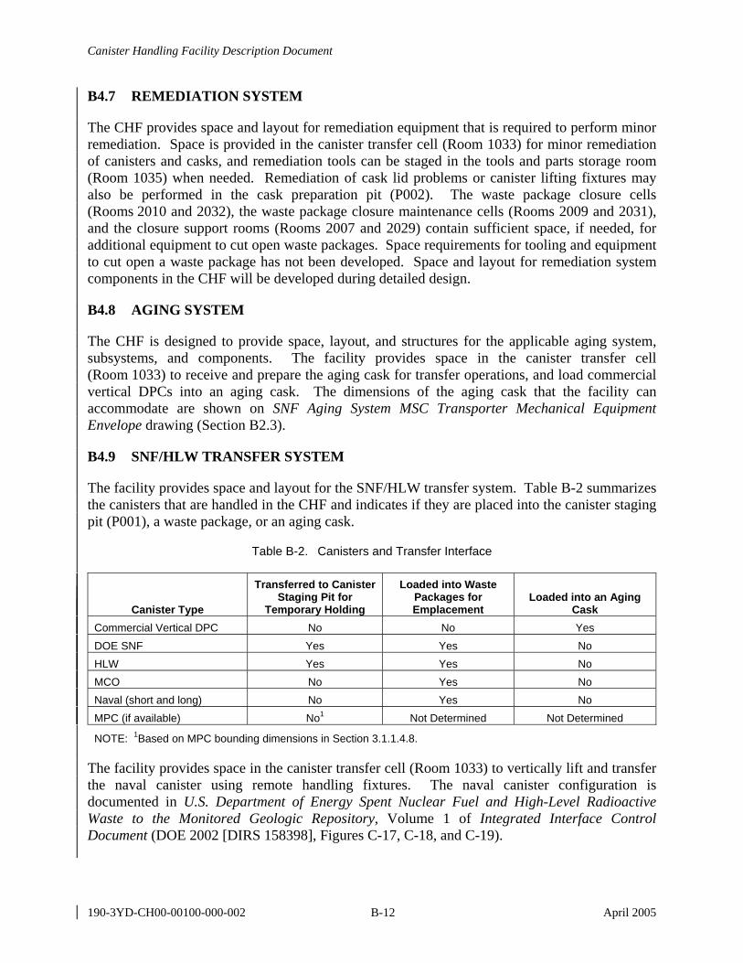
Canister Handling Facility Description Document
190-3YD-CH00-00100-000-002 B-12 April 2005
B4.7 REMEDIATION SYSTEM
The CHF provides space and layout for remediation equipment that is required to perform minor remediation. Space is provided in the canister transfer cell (Room 1033) for minor remediation of canisters and casks, and remediation tools can be staged in the tools and parts storage room (Room 1035) when needed. Remediation of cask lid problems or canister lifting fixtures may also be performed in the cask preparation pit (P002). The waste package closure cells (Rooms 2010 and 2032), the waste package closure maintenance cells (Rooms 2009 and 2031), and the closure support rooms (Rooms 2007 and 2029) contain sufficient space, if needed, for additional equipment to cut open waste packages. Space requirements for tooling and equipment to cut open a waste package has not been developed. Space and layout for remediation system components in the CHF will be developed during detailed design.
B4.8 AGING SYSTEM
The CHF is designed to provide space, layout, and structures for the applicable aging system, subsystems, and components. The facility provides space in the canister transfer cell (Room 1033) to receive and prepare the aging cask for transfer operations, and load commercial vertical DPCs into an aging cask. The dimensions of the aging cask that the facility can accommodate are shown on SNF Aging System MSC Transporter Mechanical Equipment Envelope drawing (Section B2.3).
B4.9 SNF/HLW TRANSFER SYSTEM
The facility provides space and layout for the SNF/HLW transfer system. Table B-2 summarizes the canisters that are handled in the CHF and indicates if they are placed into the canister staging pit (P001), a waste package, or an aging cask.
Table B-2. Canisters and Transfer Interface
Canister Type
Transferred to Canister Staging Pit for
Temporary Holding
Loaded into Waste Packages for Emplacement
Loaded into an Aging Cask
Commercial Vertical DPC No No Yes DOE SNF Yes Yes No HLW Yes Yes No MCO No Yes No Naval (short and long) No Yes No MPC (if available) No1 Not Determined Not Determined
NOTE: 1Based on MPC bounding dimensions in Section 3.1.1.4.8.
The facility provides space in the canister transfer cell (Room 1033) to vertically lift and transfer the naval canister using remote handling fixtures. The naval canister configuration is documented in U.S. Department of Energy Spent Nuclear Fuel and High-Level Radioactive Waste to the Monitored Geologic Repository, Volume 1 of Integrated Interface Control Document (DOE 2002 [DIRS 158398], Figures C-17, C-18, and C-19).
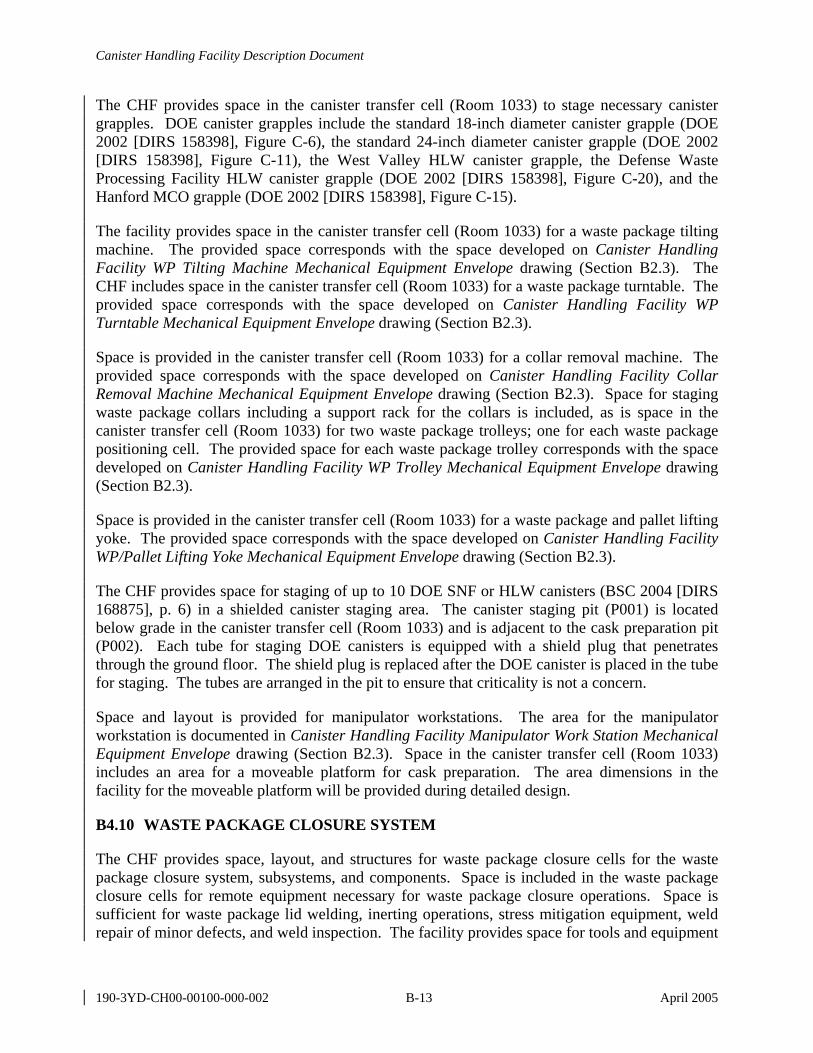
Canister Handling Facility Description Document
190-3YD-CH00-00100-000-002 B-13 April 2005
The CHF provides space in the canister transfer cell (Room 1033) to stage necessary canister grapples. DOE canister grapples include the standard 18-inch diameter canister grapple (DOE 2002 [DIRS 158398], Figure C-6), the standard 24-inch diameter canister grapple (DOE 2002 [DIRS 158398], Figure C-11), the West Valley HLW canister grapple, the Defense Waste Processing Facility HLW canister grapple (DOE 2002 [DIRS 158398], Figure C-20), and the Hanford MCO grapple (DOE 2002 [DIRS 158398], Figure C-15).
The facility provides space in the canister transfer cell (Room 1033) for a waste package tilting machine. The provided space corresponds with the space developed on Canister Handling Facility WP Tilting Machine Mechanical Equipment Envelope drawing (Section B2.3). The CHF includes space in the canister transfer cell (Room 1033) for a waste package turntable. The provided space corresponds with the space developed on Canister Handling Facility WP Turntable Mechanical Equipment Envelope drawing (Section B2.3).
Space is provided in the canister transfer cell (Room 1033) for a collar removal machine. The provided space corresponds with the space developed on Canister Handling Facility Collar Removal Machine Mechanical Equipment Envelope drawing (Section B2.3). Space for staging waste package collars including a support rack for the collars is included, as is space in the canister transfer cell (Room 1033) for two waste package trolleys; one for each waste package positioning cell. The provided space for each waste package trolley corresponds with the space developed on Canister Handling Facility WP Trolley Mechanical Equipment Envelope drawing (Section B2.3).
Space is provided in the canister transfer cell (Room 1033) for a waste package and pallet lifting yoke. The provided space corresponds with the space developed on Canister Handling Facility WP/Pallet Lifting Yoke Mechanical Equipment Envelope drawing (Section B2.3).
The CHF provides space for staging of up to 10 DOE SNF or HLW canisters (BSC 2004 [DIRS 168875], p. 6) in a shielded canister staging area. The canister staging pit (P001) is located below grade in the canister transfer cell (Room 1033) and is adjacent to the cask preparation pit (P002). Each tube for staging DOE canisters is equipped with a shield plug that penetrates through the ground floor. The shield plug is replaced after the DOE canister is placed in the tube for staging. The tubes are arranged in the pit to ensure that criticality is not a concern.
Space and layout is provided for manipulator workstations. The area for the manipulator workstation is documented in Canister Handling Facility Manipulator Work Station Mechanical Equipment Envelope drawing (Section B2.3). Space in the canister transfer cell (Room 1033) includes an area for a moveable platform for cask preparation. The area dimensions in the facility for the moveable platform will be provided during detailed design.
B4.10 WASTE PACKAGE CLOSURE SYSTEM
The CHF provides space, layout, and structures for waste package closure cells for the waste package closure system, subsystems, and components. Space is included in the waste package closure cells for remote equipment necessary for waste package closure operations. Space is sufficient for waste package lid welding, inerting operations, stress mitigation equipment, weld repair of minor defects, and weld inspection. The facility provides space for tools and equipment
Canister Handling Facility Description Document
190-3YD-CH00-00100-000-002 B-14 April 2005
that could potentially open a welded waste package. Removal of the contents and placement in a new waste package is performed in the canister transfer cell (Room 1033). Potential tooling and equipment for opening a welded waste package will be developed during detailed design.
The facility provides space for waste package closure support cranes as shown on Canister Handling Facility Closure Support Crane Mechanical Equipment Envelope drawing (Section B2.3) in the closure support rooms (Rooms 2007 and 2029). Space for waste package closure maintenance cranes as documented on Canister Handling Facility Closure Maintenance Crane Mechanical Equipment Envelope (Section B2.3) is provided in the closure maintenance rooms (Rooms 3002 and 3008). Space is provided in the waste package closure cells (Rooms 2010 and 2032) for a closure cell crane that corresponds with Mechanical Equipment Envelope Canister Handling Facility WP Closure Cell Crane (15 ton) (Section B2.3). Space for a remote manipulator in the waste package closure cells (Rooms 2010 and 2032) is provided based on Mechanical Equipment Envelope Canister Handling Facility WP Closure Cell Remote Handling Crane (3 ton) (Section B2.3).
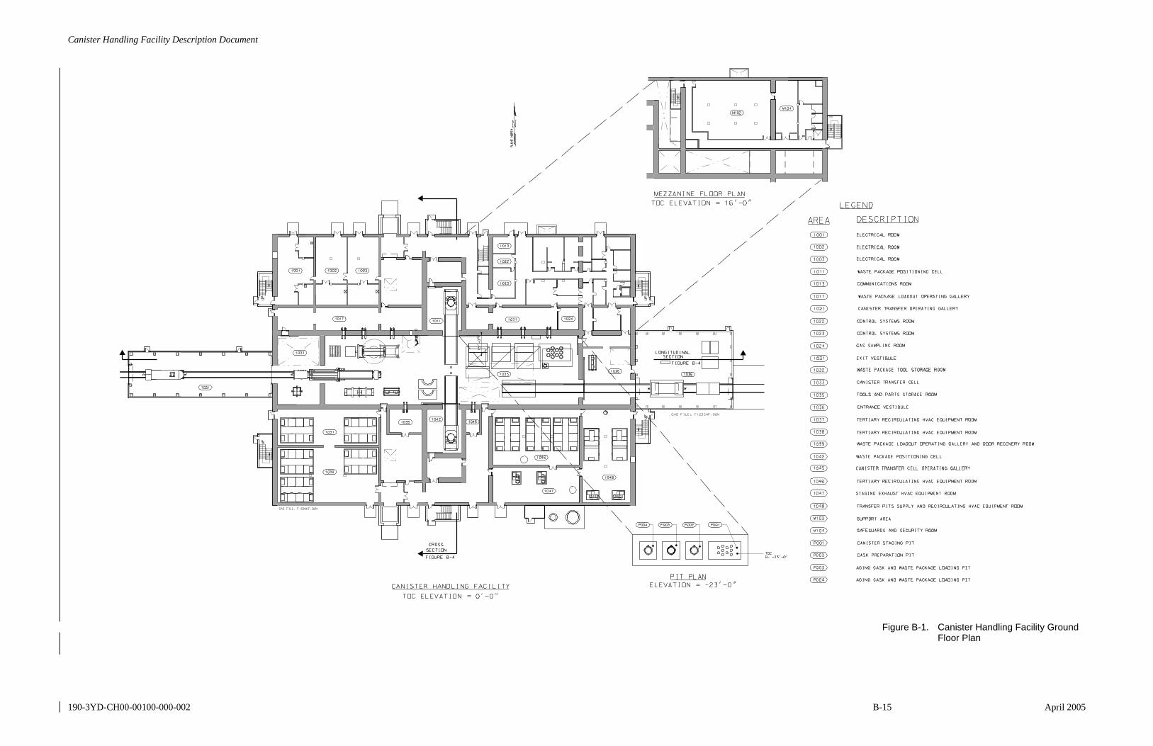
Canister Handling Facility Description Document
190-3YD-CH00-00100-000-002 B-15 April 2005
Figure B-1. Canister Handling Facility Ground Floor Plan

Canister Handling Facility Description Document
190-3YD-CH00-00100-000-002 B-16 April 2005
INTENTIONALLY LEFT BLANK
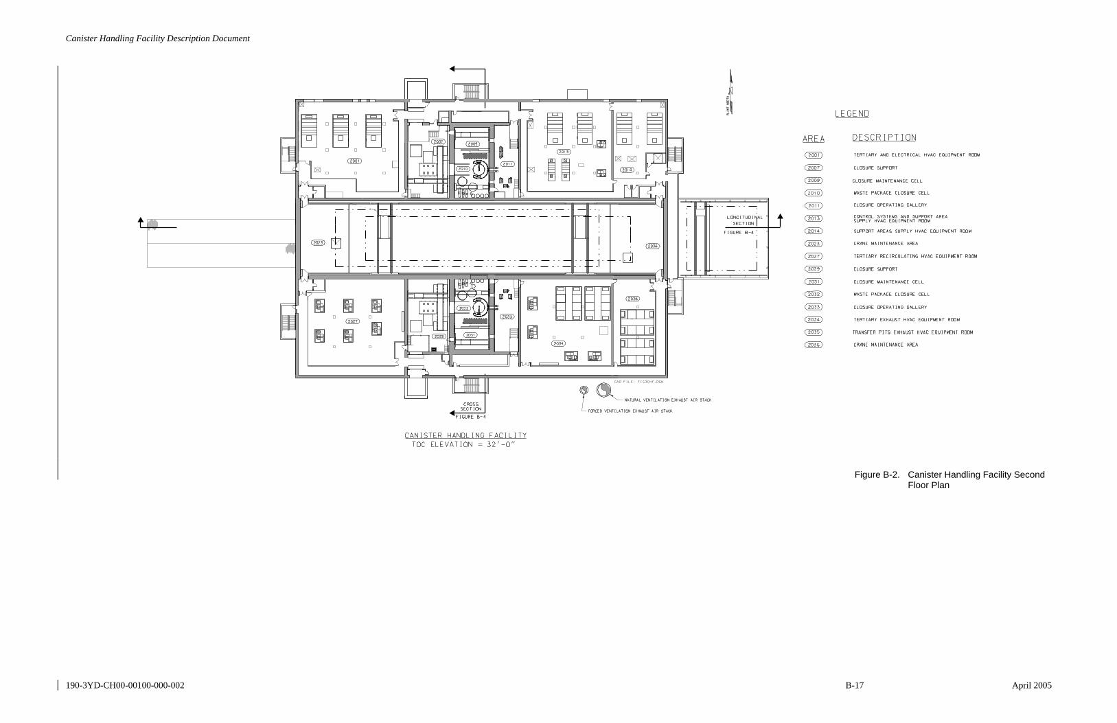
Canister Handling Facility Description Document
190-3YD-CH00-00100-000-002 B-17 April 2005
Figure B-2. Canister Handling Facility Second Floor Plan

Canister Handling Facility Description Document
190-3YD-CH00-00100-000-002 B-18 April 2005
INTENTIONALLY LEFT BLANK

Canister Handling Facility Description Document
190-3YD-CH00-00100-000-002 B-19 April 2005
Figure B-3. Canister Handling Facility Third Floor Plan

Canister Handling Facility Description Document
190-3YD-CH00-00100-000-002 B-20 April 2005
INTENTIONALLY LEFT BLANK
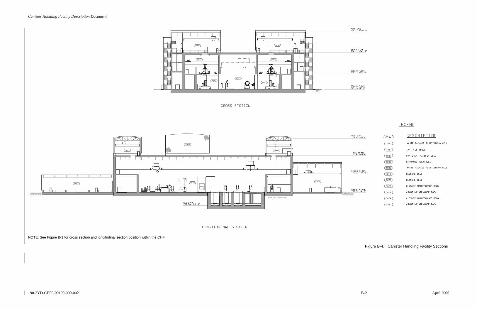
Canister Handling Facility Description Document
190-3YD-CH00-00100-000-002 B-21 April 2005
NOTE: See Figure B-1 for cross section and longitudinal section position within the CHF.
Figure B-4. Canister Handling Facility Sections

Canister Handling Facility Description Document
190-3YD-CH00-00100-000-002 B-22 April 2005
INTENTIONALLY LEFT BLANK
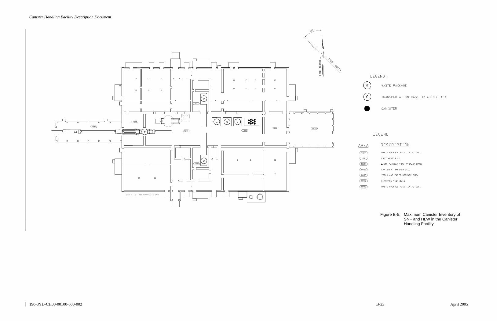
Canister Handling Facility Description Document
190-3YD-CH00-00100-000-002 B-23 April 2005
Figure B-5. Maximum Canister Inventory of SNF and HLW in the Canister Handling Facility

Canister Handling Facility Description Document
190-3YD-CH00-00100-000-002 B-24 April 2005
INTENTIONALLY LEFT BLANK
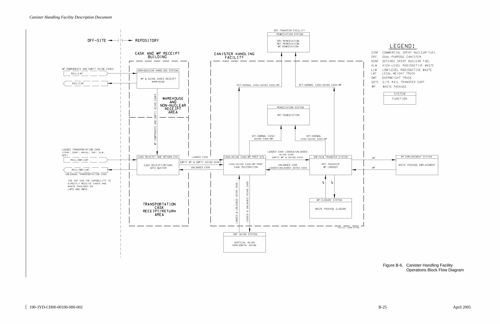
Canister Handling Facility Description Document
190-3YD-CH00-00100-000-002 B-25 April 2005
Figure B-6. Canister Handling Facility Operations Block Flow Diagram
Canister Handling Facility Description Document
190-3YD-CH00-00100-000-002 B-26 April 2005
INTENTIONALLY LEFT BLANK
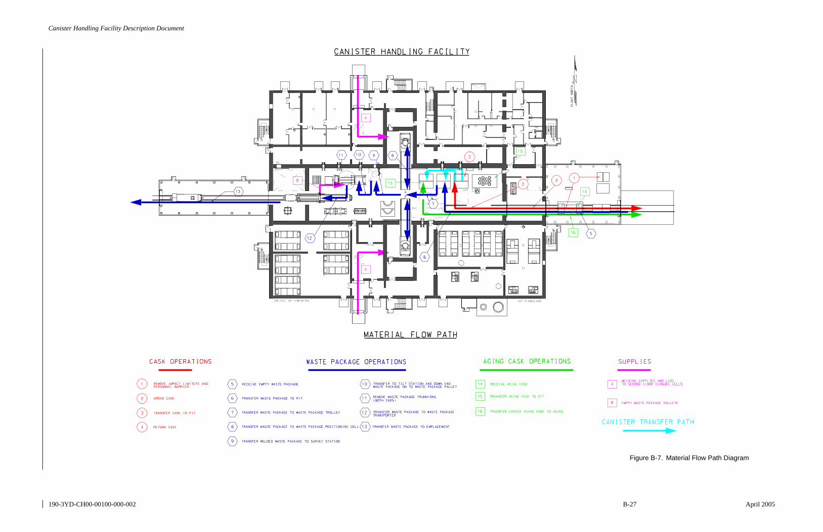
Canister Handling Facility Description Document
190-3YD-CH00-00100-000-002 B-27 April 2005
Figure B-7. Material Flow Path Diagram

Canister Handling Facility Description Document
190-3YD-CH00-00100-000-002 B-28 April 2005
INTENTIONALLY LEFT BLANK
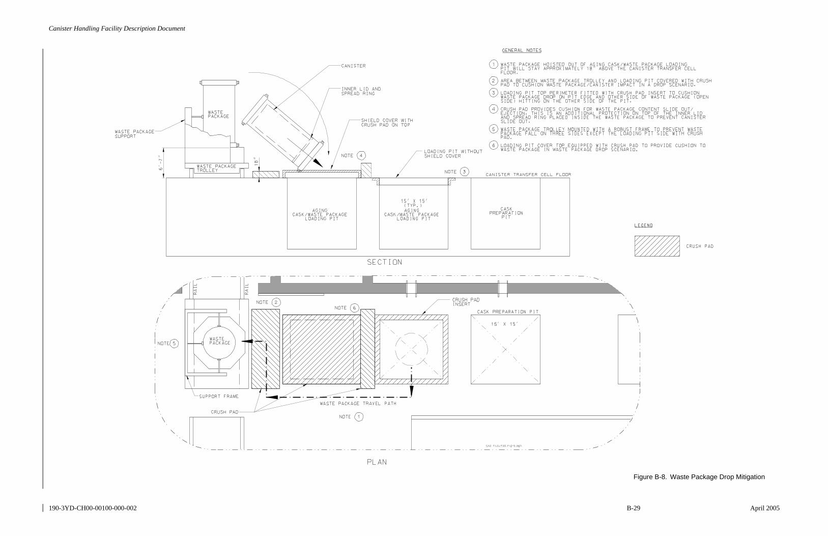
Canister Handling Facility Description Document
190-3YD-CH00-00100-000-002 B-29 April 2005
Figure B-8. Waste Package Drop Mitigation

Canister Handling Facility Description Document
190-3YD-CH00-00100-000-002 B-30 April 2005
INTENTIONALLY LEFT BLANK
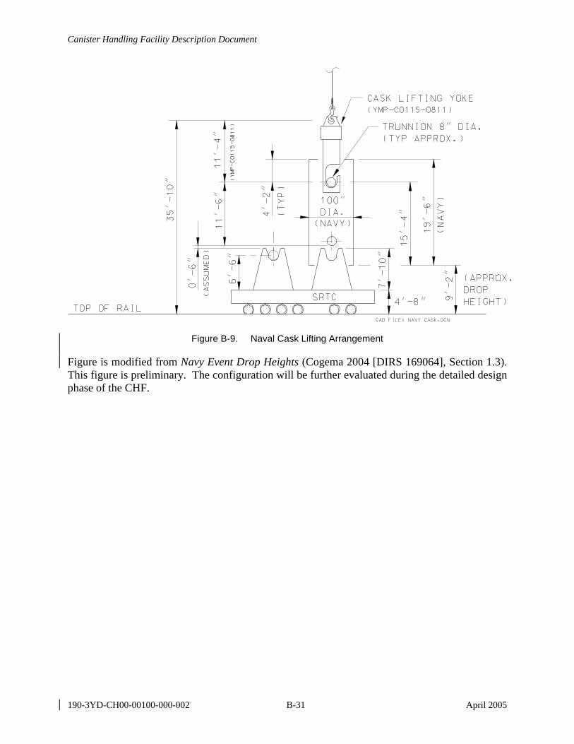
Canister Handling Facility Description Document
190-3YD-CH00-00100-000-002 B-31 April 2005
Figure B-9. Naval Cask Lifting Arrangement
Figure is modified from Navy Event Drop Heights (Cogema 2004 [DIRS 169064], Section 1.3). This figure is preliminary. The configuration will be further evaluated during the detailed design phase of the CHF.
Canister Handling Facility Description Document
190-3YD-CH00-00100-000-002 B-32 April 2005
INTENTIONALLY LEFT BLANK
Canister Handling Facility Description Document
190-3YD-CH00-00100-000-002 C-1 April 2005
APPENDIX C LIST OF FACILITY PROCEDURES
Procedures to control or operate the facility have not been developed. As these procedures are developed, they will be included in revisions to this document.
Canister Handling Facility Description Document
190-3YD-CH00-00100-000-002 C-2 April 2005
INTENTIONALLY LEFT BLANK