Campus Scaled Model
25
COVER 1 Team Leader 1 Technical Communications Design Project (95-119) Campus Scale Model Ajwad Ishaque Ankit Sharma Dale Diciocco Eniola Bibilari Matthew Vong Sabah Benou Scott Page Tyler Doyle Alfredo Salituro 1 PRESTIGE DESIGN Faculty of Engineering, University of Windsor. April 17, 2013
-
Upload
sabah-benou-eit -
Category
Documents
-
view
53 -
download
0
Transcript of Campus Scaled Model
COVER
1 Team Leader 1
Technical Communications Design Project (95-119)
Campus Scale Model
Ajwad Ishaque Ankit Sharma Dale Diciocco Eniola Bibilari Matthew Vong Sabah Benou
Scott Page Tyler Doyle
Alfredo Salituro1
PRESTIGE DESIGN
Faculty of Engineering, University of Windsor.
April 17, 2013

TITLE PAGE
1 Team Leader 2
Technical Communications Design Project (95-119)
Campus Scale Model
Ajwad Ishaque ..................................................103535973......................... [email protected] Ankit Sharma ....................................................103935517........................ [email protected] Dale Diciocco....................................................103783866............................ [email protected] Eniola Bibilari ...................................................103944629............................. [email protected] Matthew Vong ..................................................103833457............................. [email protected] Sabah Benou .....................................................103828507.............................. [email protected] Scott Page..........................................................103851604.............................. [email protected] Tyler Doyle .......................................................103825762............................ [email protected] Alfredo Salituro1 ...............................................103953876............................ [email protected]
PRESTIGE DESIGN
Faculty of Engineering, University of Windsor.
April 17, 2013

SIGNATURE PAGE
1 Team Leader 3
Campus Scale Model
The work presented in this report is solely the effort of the group members and that any work of others that was used during the execution of the design project or is included in the report has been suitably acknowledged through the standard practice of citing references and stating appropriate acknowledgments. Ajwad Ishaque 103535973 x...........................
Ankit sharma 103935517 x...........................
Dale Diciocco 103783866 x...........................
Eniola Bibilari 103944629 x...........................
Matthew Vong 103833457 x...........................
Sabah Benou 103828507 x...........................
Scott Page 103851604 x...........................
Tyler Doyle 103825762 x...........................
Alfredo Salituro1 103953876 x...........................
April 17, 2013
EXECUTIVE SUMMARY
4
Developing a three-dimensional campus map raises many challenges and must be
approached very delicately. Prestige Designs will be working with a number of competitor
companies due to the scale and time line of this project. As a result, all active parties must agree
on one format.
The landscape of this project will consist of a base in which all buildings and structures
are placed on via dowels. Due to the three-dimensional printer’s restricted printing area, the base
will consist of many smaller individual puzzle components that will be attached as one model,
once completed.
Determining the scale of the model was one of the first decisions. By outlining the
targeted area that incased all of the desired structures,Prestige Design proceeded to determine the
length of spacing using Google satellite view and measuring software. The land mass length was
then compared to the length of the surface this project was restricted to and was found to be
1:925. Using this ratio as a standard base line, a sample was printed as a reference and a base
was constructed.It was agreed upon that all road ways will be pressed down by a small factor and
sidewalks would be extruded up in order to make them more visual. The foliage surrounding the
buildings will be designed as half spheres. The surrounding features thatmany buildings had, i.e.
attaching ramps and walkways,were alsoruled to be attached to the buildings and placed on the
base.
The final and most important challenge regarding the base was determining a process to
combine the individual base sections into one whole campus map. Thestrategy Prestige Design
followed was to split the whole map into puzzle pieces, which will interlock preventing any
movement. For extra stability, the models will be fastened together using nuts and bolts. These
methods will ensure the stability and strength of a printed building.

ACKNOWLEDGEMENTS
5
Prestige Design acknowledges that the measurements taken into account for a scale of
1:925 were obtained from Google satellite view and related imaging software. Thus, with that
being said, the data may not be a hundred percent accurate due to problems emerging from
relativity. The scale used to obtain such a value (1:925) is only accurate to 500m and gives a
great chance of error. In a project where shapes and structures in real life have to be reduced for
a variety of reasons; there is always ambiguity. Everything has to be overlooked and in the end
we are all humans and mistakes will never stop to happen. In this case, the campus scale model
is a effort brought together by several other companies and is looked at as a whole. Prestige
Design is not responsible for mistakes that may occur from other parties even if a common scale
were to be used.
TABLE OF CONTENTS
6
Cover ....................................................................................................................................... Page 1
Title Page ................................................................................................................................ Page 2
Signature Page ........................................................................................................................ Page 3
Executive Summary ................................................................................................................ Page 4
Acknowledgements ................................................................................................................. Page 5
Table of Contents ................................................................................................ Page 6 (This Page)
List of Tables/Figures/Abbreviations/Symbols ...................................................................... Page 7
Chapters .............................................................................................................................................
I. Introduction ............................................................................................................. Pages 8-9
II. Literature Review and Benchmarking (Data Gathering) ................................... Pages 10-11
III. Project Work ..................................................................................................... Pages 12-17
IV. Results/Discussion/Recommendations ............................................................ Pages 18-20
V. Limitations ................................................................................................................ Page 21
VI. Conclusions & Future Work ............................................................................ Pages 22-23
References ........................................................................................................................... Pages 24
Appendices ........................................................................................................................ Pages 24+

LIST OF TABLES/FIGURES/ABBREVIATIONS/SYMBOLS
7
LIST OF FIGURES ...........................................................................................................................
Figure 1(Dorm Setup) ........................................................................................................... Page 13
Figure 2 (Floor Plan -Laurier/MacDonald)........................................................................... Page 13
Figure 3 (Vanier Floor Plan) ................................................................................................. Page 15
Figure 4 (Printed Buildings) ................................................................................................. Page 16
Figure 5 (Material being printed) .......................................................................................... Page 17
Figure 6 (Material being cooled) .......................................................................................... Page 17
Figure 7 (Material being dried) ............................................................................................. Page 17
LIST OF TABLES .............................................................................................................................
Table 1 .................................................................................................................................. Page 14
Table 2 .................................................................................................................................. Page 23
LIST OF SYMBOLS .........................................................................................................................
1 (Team Leader) ................................................................................................................. Pages 1-3

I. Introduction
CHAPTER 8
Prestige Design, along with the aid of several other firms, were tasked to build a scale
model of the University of Windsor campus. The idea originally originated from the University
of Aachen, Germany, who had done something similar. In turn this would be used as a symbol of
engineering and would be displayed somewhere beneficial. It may also be useful to note that it
was created in the Center of Engineering and Innovation building which is currently in its first
year of service to students. With that being said, it can be seen as a sign of motivation for future
engineering students or the construction workers who are adding the finishing touches.
A lot of time and effort was needed to determine the fundamental building blocks of the
design process. Teams had to cope with the physical restrictions of the Fortus 400mc printer and
generate a base in which all the campus buildings would be placed via holes and dowels. A
common scale of 1:925, in context of reality, was obtained by using Google satellite view and
other imaging software. This made it very difficult to include fine detail and colour was out of
question. Prestige Design was assigned a total of four buildings and a stadium. To clarify any
misconceptions, a sample building was created and was used as reference.
There were rumors about a name plate of all who were involved in the design process to
be showcased right next to the final physical structure. This, for Prestige Design, was a great
source of motivation as the company had employees who had studied in that university. It is not
every now and then that people get recognized by a large community for their work. "I believe
this is something I will cherish for the rest of my life and to be part of something this big is
absolutely phenomenal" - Ajwad Ishaque, employee.
With all this in mind, Prestige Design set out goals to figure out the right dimensions of a
variety of things that included anywhere from the leg height on the stadium, to benches, to the
size of a window. Because Google satellite view only provided a top view of what the team had
to work with, a physical confrontation was necessary. Pictures and videos were used as
references to aid in the proper extruding of dimensions in AutoCAD. The plan was to investigate
if the printed material would fit properly into the dowel whole on the base. There was very little
room for error as the Fortus 400mc printer not only took a great amount of time printing, but cost
a lot for the material it used. Deadlines had to be met and cost had to be at an absolute minimum.

I. Introduction
CHAPTER 9
In order to maintain business and demonstrate quality of work, Prestige Design set out to
an approach that was the norm. QR codes were generated which linked an individual building to
its description on the University of Windsor's website. These could be used to gain quick access
to information with the use of smart phones and would provide convenience. A top of the line
printer, the Fortus 400mc, was also used to precisely print the buildings to the proper scale.
Prestige Designs main priority throughout the entire build, was to design and execute our
plan with the highest level of precision and accuracy. Although faced with the burden of strict
time constraints, as well as many unforeseen complications along the way, our ability to adapt
and overcome adversity during the build ultimately lead to our overwhelming success.

II. Literature Review and Benchmarking (Data gathering)
CHAPTER 10
The tools that were used to complete this project varied from both software to physical
production. AutoCAD was used to create a three-dimensional model of the buildings the team
was assigned and was also used to print a physical model with the help of the Fortus 400mc
printer. Although this was an precise process, it occurred layer by layer which, in turn, consumed
a lot of time. With that in mind, the base was also restricted to be only as big enough to fit in the
printer, which dramatically reduced the workable size.
There was some prior work that was related to this project. In Engineering and Design, a
course taken in the previous semester, several members of the Prestige Design team were
involved in a project which incorporated anything from a drill press to a motorized car ramp.
Several views were required to demonstrate how the product was to be designed. For instance,
sketches representing top, front, side or even isometric views were required. Similarly, when
designing buildings, AutoCAD was used in which these views could easily be used and
demonstrated, but of course, no pencil drawing was needed.
Furthermore, in this course, some teams even went to the extent of creating a physical
representation of their project while others used other means such as videos to represent their
model. For Prestige Design in this case, a physical representation was printed using a 3D printer.
From Prestige Design's perspective, 3D printing would be more efficient if the printer
that was used in this project could complete print jobs faster, cheaper and have a variety of
colours. This would add a great amount of detail into the printed material and would draw more
emphasis that the current Ivory coloured material does not. The team would also like to see more
data provided for future projects as the scale that was used needed to be calculated and not only
did this lead to relativity issues, but may have created models which wereinaccurate.
Prestige Design is a business which solely runs on its clients in North America. Each
project is completed to the best of its potential buy its nine staff members. In the event of any
conspiracies or misconceptions, the business has a website from which it can ask the community
and directly talk to the client for updates/suggestions. The forum section also provides a great
way to interact with the "design" community and even exploit ideas for future projects. Topics
are monitored regularly for rules and regulations and there are weekly polls on the projects that
decide a variety of things.

II. Literature Review and Benchmarking (Data gathering)
CHAPTER 11
Even with the simplest of tasks, there are challenges that the team has to face. For
example, the printed material could deform when printed/dried/cooled and there must be enough
time before the due date to start another process. Furthermore, constant file saving on AutoCAD
was also something to consider as due to memory error, the program could crash and valuable
data may be lost. The team had to be very careful and took extra precautions to get the job done.

III. Project Work
CHAPTER 12
Methodology
Developing the three-dimensional campus map raises many challenges and must be
approached very delicately. Prestige Designs will be working with a number of competitor
companies due to the scale and time line of this project. As a result all active parties have agreed
upon our entire format. The landscape of our project will consist of a base in which all buildings
and structures will be placed on. Due to the three-dimensional printer’s restricted printing area
the base will consist of many smaller individual puzzle components that will be attached as one
model once completed.
Determining the scale of the model was one of the first decisions, which needed to be
made. By outlining our targeted area that incased all of our desired structures we proceeded to
determine the length of our space using Google satellite view and measuring software. The
length of our land mass was then compared to the length of the surface we will place our model
and the ratio was found to be 1:925. Using this ratio as a standard base line we are currently in
the process of printing a sample building to visualize the building size compared with our base
size. The challenge we currently face is determining a way to decrees the scale of our buildings
without increasing the size of our base. Seeing that our building must be correctly spaced apart
by increasing their size structures will collide and neighboring structures will not be able to be
expanded.
Once our scale was determined we proceeded to tackle smaller issues. It was agreed upon
that all road ways will be pressed down by a small factor and sidewalks would be pressed up in
order to make them more visual. The foliage surrounding the buildings will be designed as half
spheres. As well as the surrounding features many buildings had attaching ramps and walkways
that was ruled to be attached to the buildings and placed on the base.
The buildings and surrounding structures will be secured to the campus base using a
dowel system. Every building will have at least two dowels that will fit into our base with
varying diameters within a tolerance, as we will not assume 1 to 1 fitment. It was decided each
campus team will be allocated a curtain shape of dowel such as a triangle, circle, star etc. to
ensure every building is placed in its proper position. The base thickness was also debated but

III. Project Work
CHAPTER 13
ultimately consensus ruled it to be 1.5 to 2 inches, as the dowels must have enough room to
properly secure the buildings to the base.
The final and most important challenge regarding the base was determining a process to
combine the individual base sections into one whole campus map. Our strategy will be to split
the whole map into puzzle pieces, which will interlock preventing movement in the X and Z
direction. To prevent movement up and down in the Y direction we will be leaving hollow tubes
running length ways threw the model and inserting steel rods to keep the model ridged. These
methods will ensure the stability and strength of our model.
Data-analysis overview
Figure 1 Figure 2
Both Figure 1 and 2 are representations of the layout in Larier & MacDonald Hall. These drawings were used to determine how many windows the floor had on each side and the general structure.
x Two elevator chambers x 2 emergency stair wells x 19 rooms (Single Occupancy) x 4 study rooms x 4 individual rooms ( 4 corners )
III. Project Work
CHAPTER 14
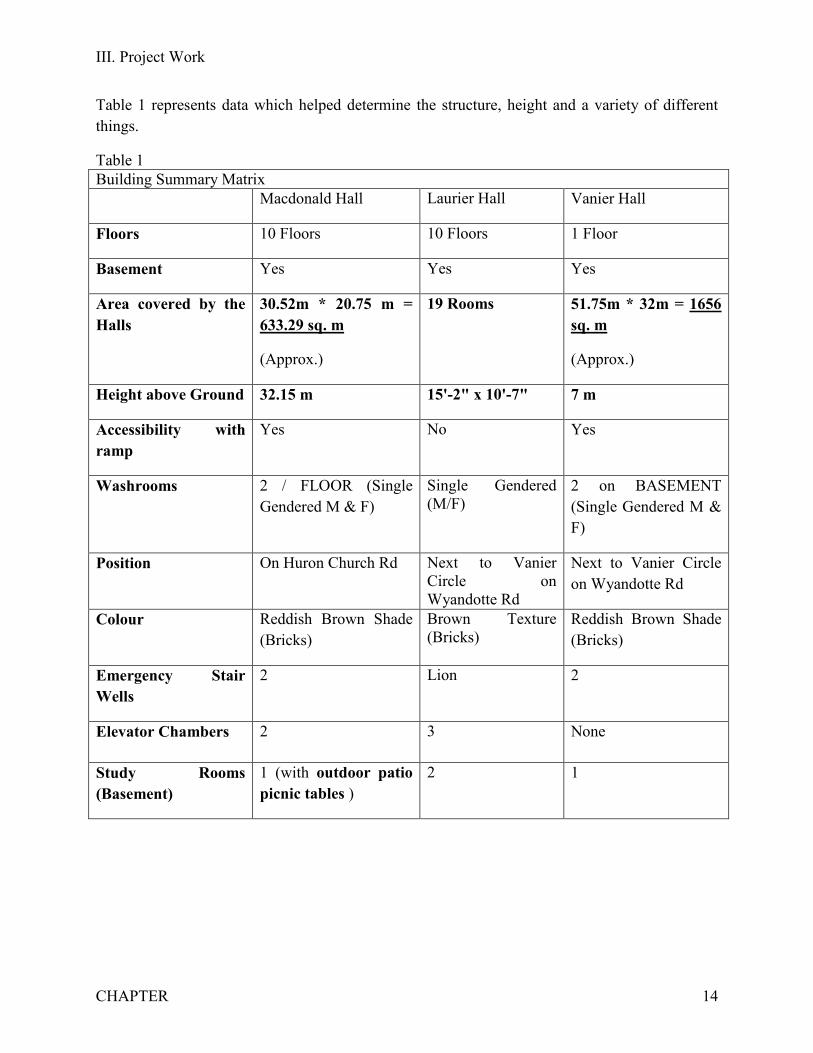
Table 1 represents data which helped determine the structure, height and a variety of different things.
Table 1 Building Summary Matrix Macdonald Hall Laurier Hall Vanier Hall
Floors 10 Floors 10 Floors 1 Floor
Basement Yes Yes Yes
Area covered by the Halls
30.52m * 20.75 m = 633.29 sq. m
(Approx.)
19 Rooms 51.75m * 32m = 1656 sq. m
(Approx.)
Height above Ground 32.15 m 15'-2" x 10'-7" 7 m
Accessibility with ramp
Yes No Yes
Washrooms 2 / FLOOR (Single Gendered M & F)
Single Gendered (M/F)
2 on BASEMENT (Single Gendered M & F)
Position On Huron Church Rd Next to Vanier Circle on Wyandotte Rd
Next to Vanier Circle on Wyandotte Rd
Colour Reddish Brown Shade (Bricks)
Brown Texture (Bricks)
Reddish Brown Shade (Bricks)
Emergency Stair Wells
2 Lion 2
Elevator Chambers 2 3 None
Study Rooms (Basement)
1 (with outdoor patio picnic tables )
2 1
III. Project Work
CHAPTER 15
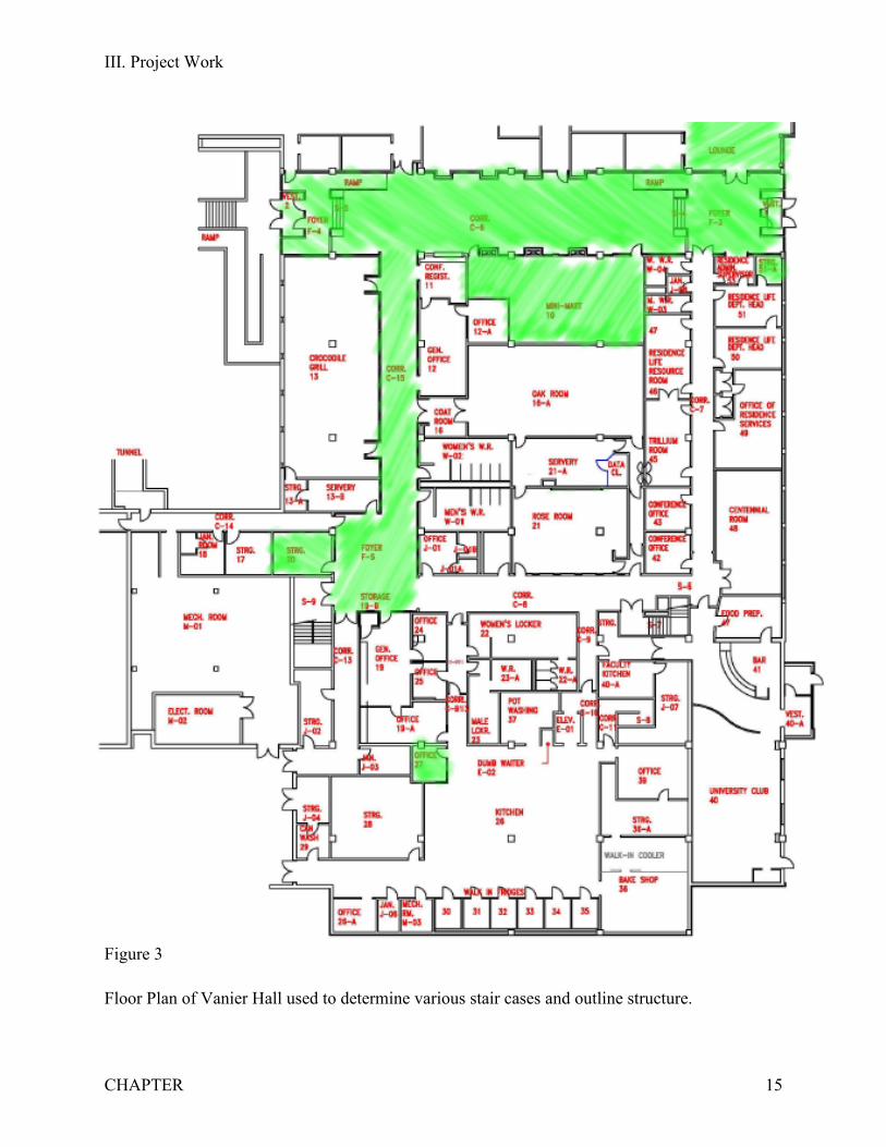
Figure 3
Floor Plan of Vanier Hall used to determine various stair cases and outline structure.
III. Project Work
CHAPTER 16
Design Overview
The customer required a scale model of the University of Windsor's campus. A total of
eleven groups were involved with this massive project and several methods were used to develop
the final design. At first a scale of 1/925 was determined and from there, with the aid of pictures
and references, a base was created on AutoCAD. It was then printed using a 3D printer called the
Fortus 400mc which only printed in ivory coloured material and building layouts were
determined. Google Earth, Satellite View and several other global imaging software along with
pictures and references were used to construct the scaled versions of the buildings (Cartier,
Vanier, MacDonald, Laurier & Stadium) that were assigned to Prestige Design. Several
constraints were met by either the location of the buildings or their size. For example, a portion
of the stadium had to be removed in order to fit the south-west corner of the base. The University
of Windsor logo on top of Laurier Hall had to be also removed due to the text size being very
small.
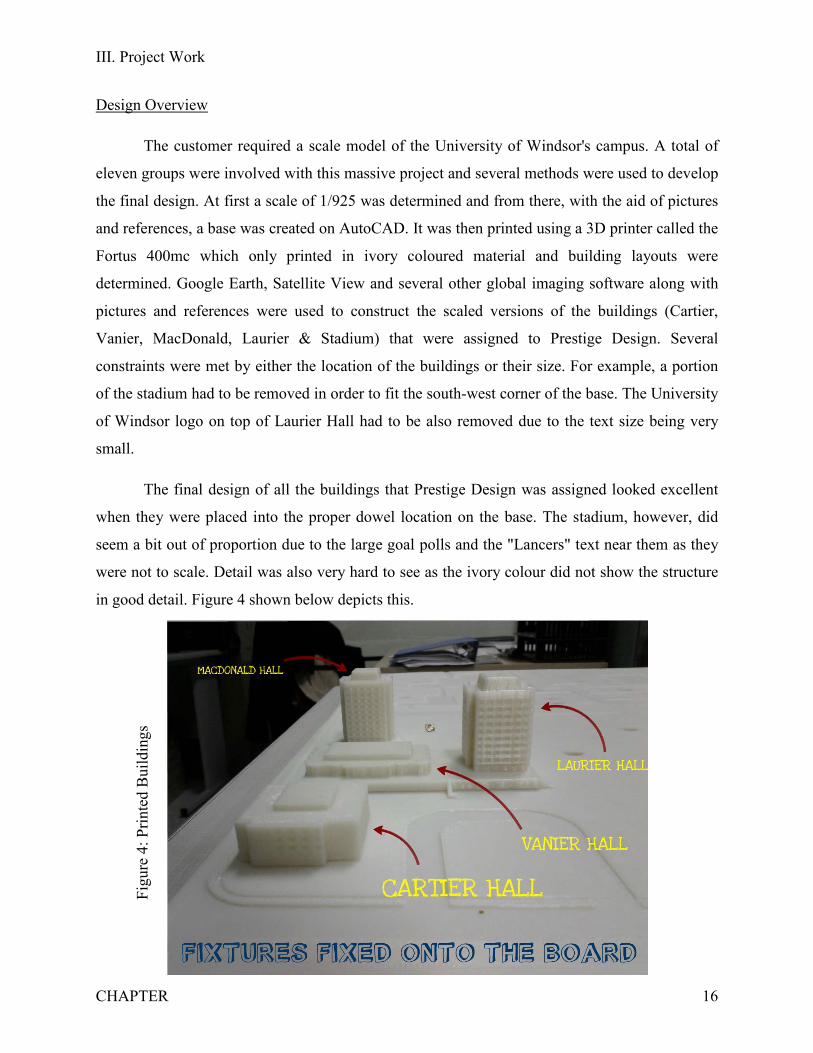
The final design of all the buildings that Prestige Design was assigned looked excellent
when they were placed into the proper dowel location on the base. The stadium, however, did
seem a bit out of proportion due to the large goal polls and the "Lancers" text near them as they
were not to scale. Detail was also very hard to see as the ivory colour did not show the structure
in good detail. Figure 4 shown below depicts this.
Figu
re 4
: Prin
ted
Bui
ldin
gs

III. Project Work
CHAPTER 17
In order to manufacture the product, a drawing on AutoCAD needed to be scaled
properly and then sent to the Fortus 400mc printer in which the building took a moderate time
based on the building complexity to print. It then had to be cooled and dried for some time
before being placed on the base. This process was then repeated for each individual building
until the base-assigned portion was complete.
During the infancy of the project, a sample of Laurier Hall at a scale of 1:920 was printed
but after some analysis was found to be too big compared to its base. Having this experience also
arose a new way to design the buildings. At first a fully solid model was constructed without the
hollow surface inside because cost of material was neglected but when taken to print the
instructor asked that it be hollow. The Ivory material that was used is fairly expensive at roughly
$13 per inch cubed. With that in mind, there was no room for error, not only because it cost a
significant amount for the material but because the time it took from being printed to being
placed on the base was quite noteworthy. Figures 5, 6 and 7 show this process.
Figu
re 5
: Mat
eria
l bei
ng p
rinte
d. Figure 6: M
aterial being cooled.
Figure 7: Material being dried.

IV. Results/Discussion/Recommendations
CHAPTER 18
Prestige Design was tasked with the goal of modelling, and recreating 4 main buildings
of the University of Windsor, along with the stadium. Our group was one of the eleven total
teams to be tasked with building a scale replica of the campus. This was not only a benefit, but
also a detriment to our task. Working with other teams allows more ideas to come across the
table, but it also allows for more confusion and stubbornness. However, Prestige Design is a
professional company that can handle pressure, confusion and heavy workloads. We encountered
numerous roadblocks but overcame even the toughest of them.
Working with other groups was no walk in the park. Meeting with each team leader (if
any) was a hassle, and many did not show. After finally splitting up the work, and agreeing on
who got what part of the campus, agreeing on scales, base attachments and team meetings was a
challenge on its own, not to mention the cancelled team meetings. This was a problem that
Prestige Design did not expect to encounter. A professional group working on a seriously large
project like this should have the professionalism to carry out the task while working beside other
professionals. This obstacle however was overcome, work continued and eventually
communication improved.
After sorting out groups and splitting up the work accordingly, the next roadblock was
how to dimension the buildings. Taking photographs, eye balling measurements, or counting
pixels of pictures was not the best way to achieve an exact scale and proportional model. To
overcome this, an engineer in Prestige Designs team brought to our attention that Google Maps
has a measurement tool, free on the web. After finding that we could measure the buildings from
Google Maps, we passed this information onto the other 10 groups, to allow a uniform scale (m)
and to help ease the workload. After all the dimensions of the building were put into AutoCAD,
they now needed to be scaled down to a uniform scale to fit onto the base. A scale of 1/925 was
found to be the scale needed for the size of our scale model. This number was sent to each group
and ensured that each building was proportional to the rest. Prestige Design took charge and
worked with the head of the 3D printing system, to ensure that the ideas we had come up with to
solve the problem at hand were going to work flawlessly. Another problem that arose was how to
securely attach the group’s buildings to the provided board. It eventually led to the compromise
of 9mm dowels on the underside of each building, that fit directly into the board, snugly and
securely. This ensured that all of our scale models would work together.

IV. Results/Discussion/Recommendations
CHAPTER 19
Researching each building and knowing every detail about it was key to the success of
this project. Not only was there supposed to be a solid model representation of the building, there
was also supposed to be a QR-code linked with the individual buildings that brought you to a
webpage for each individual building. This is a very neat feature of this project, and our web
designers went straight to work. Our research and development team found all the information of
our buildings, and what was left was a beautiful website devoted to each building. Information
such as; furniture, recreation, fire exits, accessibility, security, build dates, renovations, and
much more.
Our results with the solid models were very much trial and error. To secure our buildings
to the bases provided, we need a way of attaching them. Ideas were tossed around in the
engineering group of Prestige Design, and the other groups, and a dowel was agreed upon. This
solved one issue, but also presented another; the size of the dowel. At first the dowels and dowel
holes were going to be equally 10mm, but the dowels would not go into the slot, so slight
adjustments had to be made. The next trial was the thickness of the buildings. It was not
economical to print all the buildings solid. So a general thickness of the base and sides had to be
agreed upon between groups. Through trial, we determined that the best thickness to hold
structurally and securely, while minimizing cost was to have a thickness of 2mm. Our results
were very useful not only to our portion of the work, but also to the groups working on the same
project. Another issue that arose, was the texturing of the buildings and stadium. Prestige Design
wanted to represent the buildings as best as we could, but with the machine not allowing the
precision needed to show grass or brick texture, we had to discard that idea, and in return put
more effort into the outsides characteristics of the buildings.
Our research and tasking approach worked perfectly. Splitting up the work fairly and
evenly in Prestige design was our main focus. Group members who lived in a building that was
assigned in our project were tasked with finding out the information about it. This made it more
convenient for those who knew nothing about them previously. Our approach is to minimize
time and effort to benefit the client, and we stuck to this. Those who were good in AutoCAD
were tasked with more detailed buildings, and those good with web designing, designed the QR-
code based sites. One thing our team did to ensure the best and brightest ideas were portrayed,
was when there wasn’t enough work to divvy up evenly, multiple people were tasked with the
IV. Results/Discussion/Recommendations
CHAPTER 20
same work, and the best was chosen, or the information was compiled. Our team work was
extremely beneficial to the success of our project. Prestige design’s main goal was to make sure
that every member felt embraced in what they were tasked in, and making sure that they were
interested on the topic.
Our deliverables were met consistently, and well done. With our extremely co-operative
team, and our work habits, we delivered our tasks on time, and thoroughly done. An
improvement however could be more regular team meetings. It was very difficult to find times
where the whole group could meet due to labs and classes. This left some members in the dark,
and more effort was needed to bring them up to par. A team meeting during class, if everyone
showed, would have been beneficial.
Our over results and findings of this project were outstanding. From working with other
teams to printing the buildings out, many new findings were brought to attention, and all were
tackled by Prestige Designs immaculate team of engineers. New findings and problems are
always present when a project is done for the first time, and Prestige Design believes that all of
these were handled with more care than needed. Our goals were set to perfection, and perfection
we achieved.
V. Limitations
CHAPTER 21
Due to not having blueprints and detailed dimensions of the buildings, not all
measurements were exact. When using Google Earth to extract the dimensions of the outlines of
the buildings and their details, the “ruler” tool was used. This tool gave an idea of the exact
dimensions of the buildings, however as stated before was not 100% accurate. If blueprints and
detailed dimensions of buildings were given, then exact dimensions would have been used.
Another limitation was the scale. When using a scale of 1:925, small details were omitted when
the buildings were printed. For example, the “University of Windsor” sign on top of Macdonald
Hall was drawn on the model in AutoCAD; however, when scaled down to 1:925, it was too
small for the Fortus 400mc to print. Lastly, another limitation was the lack of colour and texture
of the models. If colour and texture was an option, then the bricks and their colours would have
been noticeable on the buildings, along with other small details. However, due to the Fortus
400mc only being able to print ivory coloured plastic, one colour was used for all models.
Overall, most of the limitations were small and not very detrimental to the final product.

VI. Conclusions and Future Work
CHAPTER 22
Throughout the course of this project, our team has been able to learn many
valuable skills, encompassing both technical work, and working as a group. The members
of the group can now use the various tools of the AutoCAD software adequately enough
to design or model many different, and more complex buildings or other items, as a result
of modeling the campus buildings. This is a very valuable skill to have as AutoCAD is
applied in every field of engineering, and knowing how to use the program looks good on
resumes. We have learned how to use several different measurement tools that are readily
available, which allow anyone to easily measure dimensions of buildings and roadways,
and we have learned the processes of 3D-printing, an emerging technology that we will
all see in our future.
On the non-technical side of things, the project forced us to communicate well
with the entire team to ensure that what needed to be completed was finished on time,
and that the work was as expected, and of high quality. The team was not only well
organized, but we were also dedicated to completing this project, and obtaining the
highest possible quality of work, while working together to overcome any and all
obstacles that we encountered. Throughout the project, various tasks were assigned to
each member of the team, and there was never a problem with the work not being
completed on time. Everyone was eager to help the other members of the team, even if
they were not asked to, and the work was shared evenly throughout all team members
because of this. The team worked together perfectly, and all of the team members formed
friendships that will last a lifetime.
Overall, this project proved to be a valuable experience for all of the participating
students, especially the members of Prestige Design. The skills we learned through the
course of completing this project will be very useful in future workplaces, and when
applying for jobs in the future.
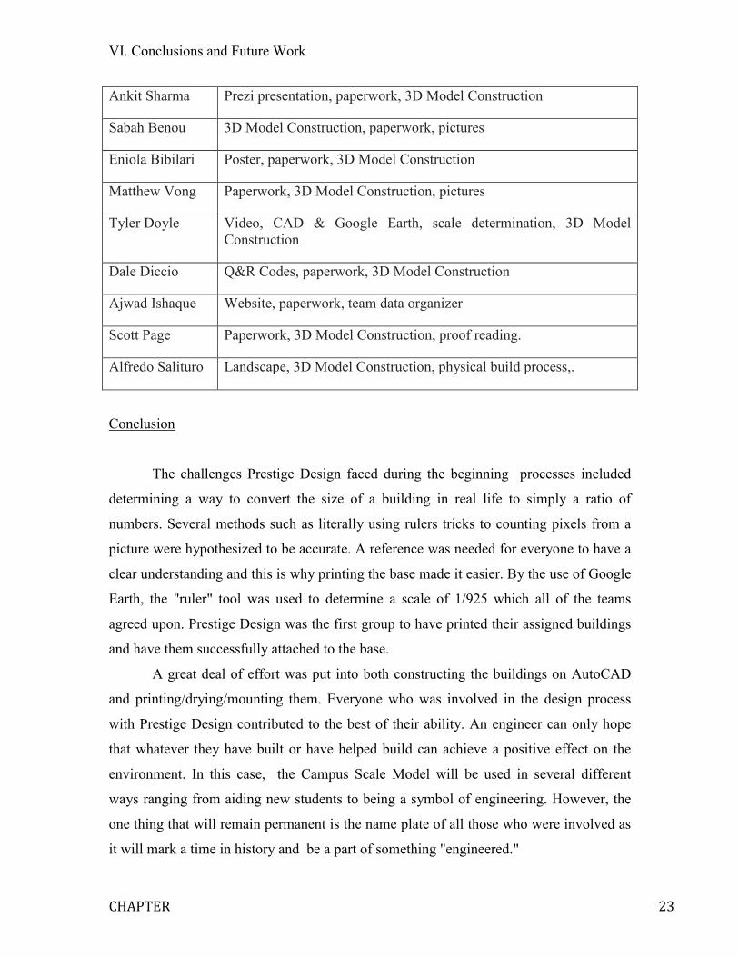
Appendix
Table 2 is a brief summary of each person's contribution.
VI. Conclusions and Future Work
CHAPTER 23
Ankit Sharma Prezi presentation, paperwork, 3D Model Construction
Sabah Benou 3D Model Construction, paperwork, pictures
Eniola Bibilari Poster, paperwork, 3D Model Construction
Matthew Vong Paperwork, 3D Model Construction, pictures
Tyler Doyle Video, CAD & Google Earth, scale determination, 3D Model Construction
Dale Diccio Q&R Codes, paperwork, 3D Model Construction
Ajwad Ishaque Website, paperwork, team data organizer
Scott Page Paperwork, 3D Model Construction, proof reading.
Alfredo Salituro Landscape, 3D Model Construction, physical build process,.
Conclusion
The challenges Prestige Design faced during the beginning processes included
determining a way to convert the size of a building in real life to simply a ratio of
numbers. Several methods such as literally using rulers tricks to counting pixels from a
picture were hypothesized to be accurate. A reference was needed for everyone to have a
clear understanding and this is why printing the base made it easier. By the use of Google
Earth, the "ruler" tool was used to determine a scale of 1/925 which all of the teams
agreed upon. Prestige Design was the first group to have printed their assigned buildings
and have them successfully attached to the base.
A great deal of effort was put into both constructing the buildings on AutoCAD
and printing/drying/mounting them. Everyone who was involved in the design process
with Prestige Design contributed to the best of their ability. An engineer can only hope
that whatever they have built or have helped build can achieve a positive effect on the
environment. In this case, the Campus Scale Model will be used in several different
ways ranging from aiding new students to being a symbol of engineering. However, the
one thing that will remain permanent is the name plate of all those who were involved as
it will mark a time in history and be a part of something "engineered."

REFERENCES
24
"About the St. Denis Centre." University of Windsor Lancers. N.p., n.d. Web. 11 Apr. 2013.
<www.golancers.ca/sports/2009/8/20/About%20St%20Denis%20Centre.aspx?tab=stden
iscentre>.
"Cartier Hall | Residence - University of Windsor." University of Windsor. N.p., n.d. Web. 11
Apr. 2013. <http://www.uwindsor.ca/residence/cartier-hall>.
"Laurier Hall | Residence - University of Windsor." University of Windsor. N.p., n.d. Web. 11
Apr. 2013. <http://www.uwindsor.ca/residence/laurier-hall>.
"Macdonald Hall | Residence - University of Windsor." University of Windsor. N.p., n.d. Web.
11 Apr. 2013. <http://www.uwindsor.ca/residence/macdonald-hall>.
"Vanier Hall." Classroom Database. N.p., n.d. Web. 11 Apr. 2013.
<apps.medialab.uwindsor.ca/classrooms/VH/>.

APPENDIX