Campus Distribution (Cisco Catalyst 4500) QoS Design...Chapter 15: Campus Distribution (Cisco...
40
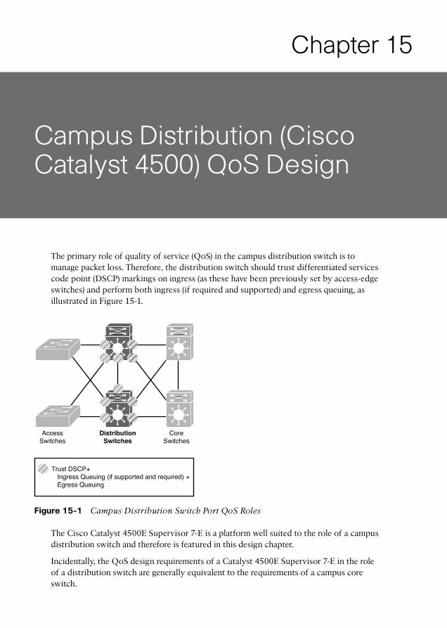
Chapter 15 Campus Distribution (Cisco Catalyst 4500) QoS Design The primary role of quality of service (QoS) in the campus distribution switch is to manage packet loss. Therefore, the distribution switch should trust differentiated services code point (DSCP) markings on ingress (as these have been previously set by access-edge switches) and perform both ingress (if required and supported) and egress queuing, as illustrated in Figure 15-1. Trust DSCP+ Ingress Queuing (if supported and required) + Egress Queuing Distribution Switches Access Switches Core Switches Figure 15-1 Campus Distribution Switch Port QoS Roles The Cisco Catalyst 4500E Supervisor 7-E is a platform well suited to the role of a campus distribution switch and therefore is featured in this design chapter. Incidentally, the QoS design requirements of a Catalyst 4500E Supervisor 7-E in the role of a distribution switch are generally equivalent to the requirements of a campus core switch.
Transcript of Campus Distribution (Cisco Catalyst 4500) QoS Design...Chapter 15: Campus Distribution (Cisco...
Chapter 15
Campus Distribution (Cisco Catalyst 4500) QoS Design
The primary role of quality of service (QoS) in the campus distribution switch is to manage packet loss. Therefore, the distribution switch should trust differentiated services code point (DSCP) markings on ingress (as these have been previously set by access-edge switches) and perform both ingress (if required and supported) and egress queuing, as illustrated in Figure 15-1 .
Trust DSCP+ Ingress Queuing (if supported and required) + Egress Queuing
DistributionSwitches
AccessSwitches
CoreSwitches
Figure 15-1 Campus Distribution Switch Port QoS Roles
The Cisco Catalyst 4500E Supervisor 7-E is a platform well suited to the role of a campus distribution switch and therefore is featured in this design chapter.
Incidentally, the QoS design requirements of a Catalyst 4500E Supervisor 7-E in the role of a distribution switch are generally equivalent to the requirements of a campus core switch.
276 End-to-End QoS Network Design
Cisco Catalyst 4500 QoS Architecture
From a QoS perspective, the Cisco Catalyst 4500-E Supervisor 7-E is nearly identical to the Supervisor 6-E platform and the Catalyst 4500-X, because all of these platforms are Modular QoS command-line interface (MQC) based. However, earlier Catalyst 4500 plat-forms (such as the Supervisor II-Plus through Supervisor V-10GE) are Multi-Layer Switch (MLS)-QoS-based platforms and are referred to as Classic Supervisors .
Note QoS design for these older Classic Supervisors is beyond the scope for this design chapter. However, you can find design guidance for these platforms at http://www.cisco.com/en/US/docs/solutions/Enterprise/WAN_and_MAN/QoS_SRND_40/QoSCampus_40.html#wp1099634 .
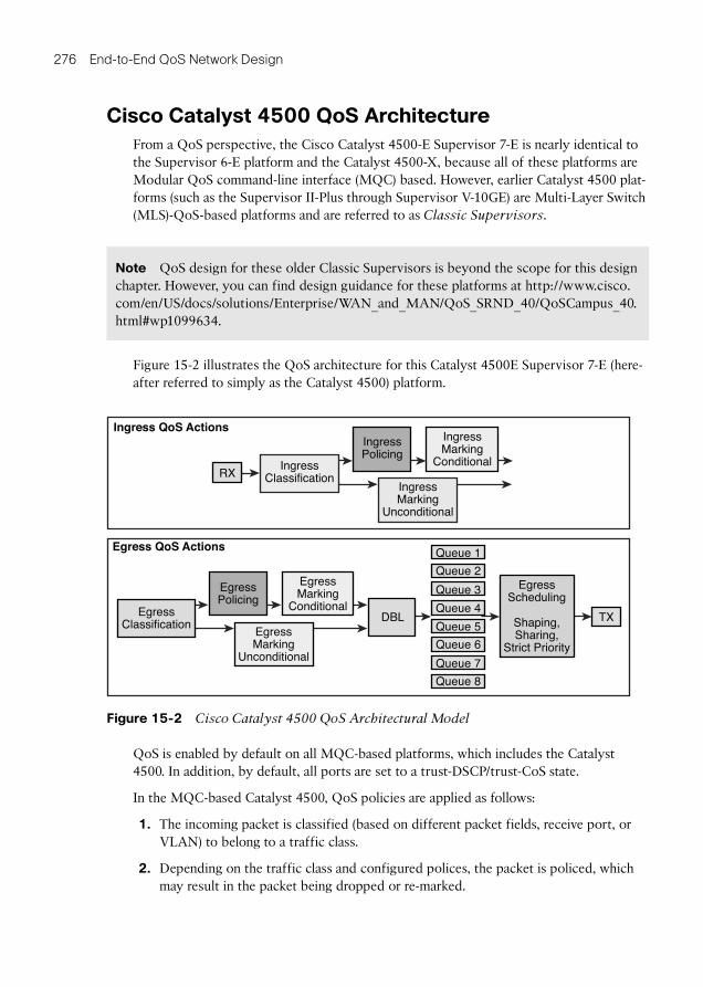
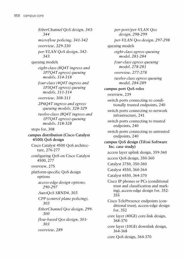
Figure 15-2 illustrates the QoS architecture for this Catalyst 4500E Supervisor 7-E (here-after referred to simply as the Catalyst 4500) platform.
Queue 1
Queue 2
Ingress QoS ActionsIngressMarking
Conditional
IngressMarking
Unconditional
IngressClassificationRX
IngressPolicing
Egress QoS Actions
EgressMarking
Conditional
EgressMarking
Unconditional
DBLEgressClassification
Queue 3
Queue 4
Queue 5
Queue 6
Queue 7
Queue 8
Shaping,Sharing,
Strict Priority
EgressScheduling
TX
EgressPolicing
Figure 15-2 Cisco Catalyst 4500 QoS Architectural Model
QoS is enabled by default on all MQC-based platforms, which includes the Catalyst 4500. In addition, by default, all ports are set to a trust-DSCP/trust-CoS state.
In the MQC-based Catalyst 4500, QoS policies are applied as follows:
1. The incoming packet is classified (based on different packet fields, receive port, or VLAN) to belong to a traffic class.
2. Depending on the traffic class and configured polices, the packet is policed, which may result in the packet being dropped or re-marked.
Chapter 15: Campus Distribution (Cisco Catalyst 4500) QoS Design 277
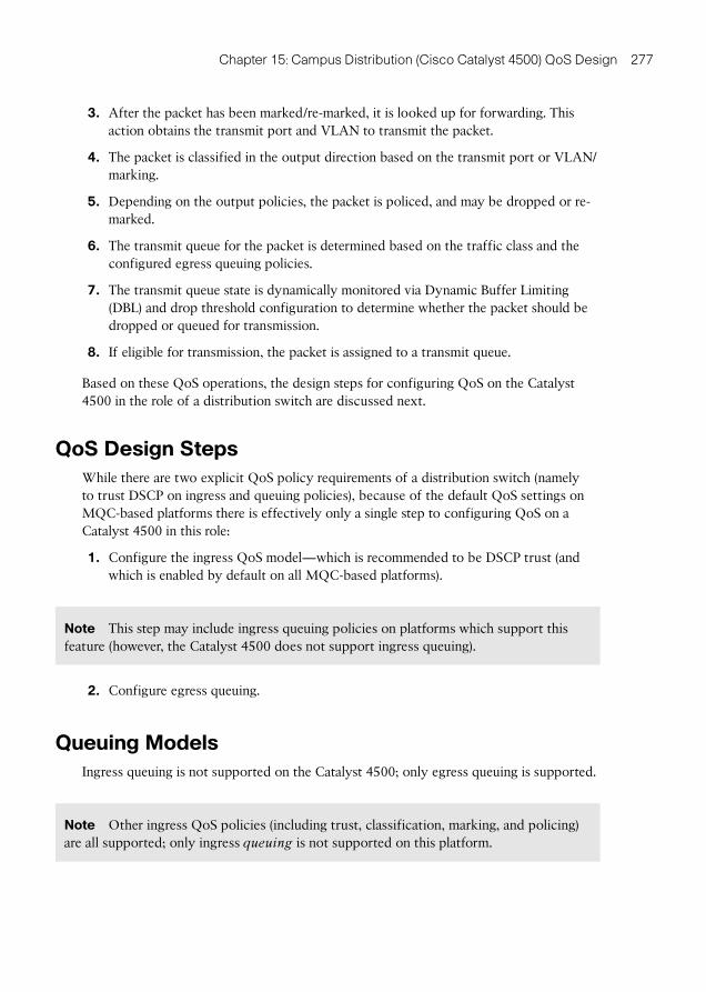
3. After the packet has been marked/re-marked, it is looked up for forwarding. This action obtains the transmit port and VLAN to transmit the packet.
4. The packet is classified in the output direction based on the transmit port or VLAN/marking.
5. Depending on the output policies, the packet is policed, and may be dropped or re-marked.
6. The transmit queue for the packet is determined based on the traffic class and the configured egress queuing policies.
7. The transmit queue state is dynamically monitored via Dynamic Buffer Limiting (DBL) and drop threshold configuration to determine whether the packet should be dropped or queued for transmission.
8. If eligible for transmission, the packet is assigned to a transmit queue.
Based on these QoS operations, the design steps for configuring QoS on the Catalyst 4500 in the role of a distribution switch are discussed next.
QoS Design Steps
While there are two explicit QoS policy requirements of a distribution switch (namely to trust DSCP on ingress and queuing policies), because of the default QoS settings on MQC-based platforms there is effectively only a single step to configuring QoS on a Catalyst 4500 in this role:
1. Configure the ingress QoS model—which is recommended to be DSCP trust (and which is enabled by default on all MQC-based platforms).
Note This step may include ingress queuing policies on platforms which support this feature (however, the Catalyst 4500 does not support ingress queuing).
2. Configure egress queuing.
Queuing Models
Ingress queuing is not supported on the Catalyst 4500; only egress queuing is supported.
Note Other ingress QoS policies (including trust, classification, marking, and policing) are all supported; only ingress queuing is not supported on this platform.
278 End-to-End QoS Network Design
The Catalyst 4500 supports a strict-priority hardware queue with (up to) seven additional nonpriority hardware queues. In addition, the Catalyst 4500 supports DSCP-to-queue mapping.
At the time of this writing, DSCP-based weighted random early detection (WRED) is not supported on the Catalyst 4500 platform. However, the Catalyst 4500 family uses a platform-specific congestion avoidance algorithm to provide active queue management (AQM), namely Dynamic Buffer Limiting (DBL). DBL tracks the queue length for each traffic flow in the switch. When the queue length of a flow exceeds its limit, DBL drop packets or sets the Explicit Congestion Notification (ECN) bits in the packet headers. The DBL algorithm can identify belligerent flows (that is, unchecked/nonadaptive/inelastic flows) and drop these more aggressively. Belligerent flows can use excessive bandwidth and switch buffers, resulting in poor application performance for well-behaved flows. Therefore, DBL can induce not only random “probabilistic drops” (in a manner similar to WRED), but also “belligerent flow drops,” both of which are counted and displayed via the show policy-map interface command output on classes where DBL has been enabled (as demonstrated later in Example 15-4 ).
Therefore, the egress queuing model for the Catalyst 4500 platform can be expressed as 1P7Q1T+DBL.
Note DBL is unique to the Catalyst 4500 platforms. At the time of this writing, there are no tuning options for DBL.
The Catalyst 4500 can be configured to support 4-class, 8-class, or 12-class queuing models, as discussed in the following sections.
Four-Class Egress Queuing Model
In the four-class model (illustrated in Figures 11-3 and 11-4 in Chapter 11 , “QoS Design Principles and Strategies”), the application class to queue mappings are as follows:
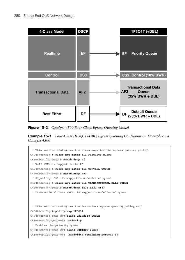
Real-time traffic (marked EF) is assigned to the priority queue (which may be option-ally policed to 30 percent bandwidth).
Control traffic (marked CS3) is assigned to a dedicated nonpriority queue with a 10 percent bandwidth allocation.
Transactional data (marked AF2) is assigned to another dedicated nonpriority queue with a 35 percent bandwidth allocation with DBL enabled.
Best-effort traffic (marked DF) is assigned to a default queue with 25 percent band-width allocation with DBL enabled.
Chapter 15: Campus Distribution (Cisco Catalyst 4500) QoS Design 279
Note DBL is enabled only on the transactional data queue and the default queue (because real-time traffic and control traffic should never be early dropped).
Note When the priority queue is configured on one class of a policy map without a policer, only bandwidth remaining percent is accepted on other classes (guaranteeing a minimum bandwidth for other classes from the remaining bandwidth of what is left after using the priority queue). However, when the priority queue is configured with a policer, either bandwidth percent or bandwidth remaining percent is accepted on the other queuing classes.
Note If queuing policies are to be applied to EtherChannel interfaces, it is recommended not to police the priority queue. This is because two policy maps would be needed in this case: One policy map would be needed to police the priority queue (which would have to be applied to the logical EtherChannel interface in the egress direction), and a second policy map would be needed to define the queuing policy (using bandwidth remaining percent), which would be applied to all EtherChannel physical port-member interfaces in the egress direction. Therefore, to simplify the queuing policy and to increase its portability and modularity, the priority queue is not policed in the queuing design examples in this chapter (which necessitates the use of bandwidth remaining percent on nonpriority queues).
Note Although it is true that there will be fractional differences in bandwidth allotments to an application class depending on whether bandwidth percent or bandwidth remaining percent is used. However, because these differences are relatively minor, the same numeric values are used in these examples for the sake of consistency.
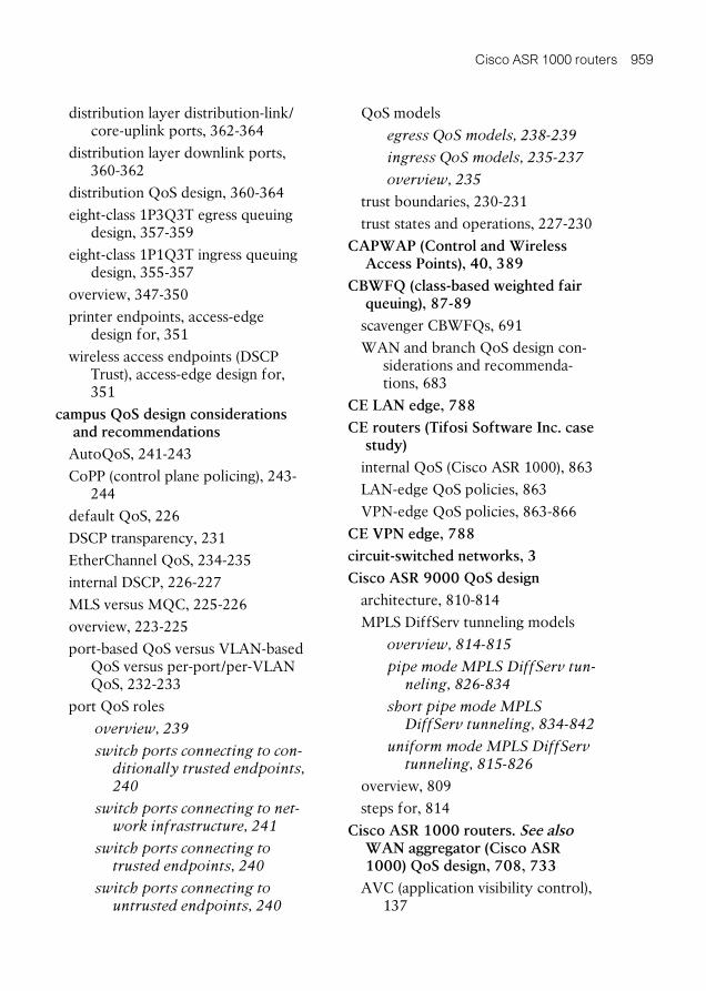
Figure 15-3 illustrates the resulting four-class (1P3Q1T+DBL) egress queuing model for the Catalyst 4500.
Example 15-1 shows the corresponding configuration for four-class (1P3Q1T+DBL) egress queuing on the Catalyst 4500.
280 End-to-End QoS Network Design
Example 15-1 Four-Class (1P3Q1T+DBL) Egress Queuing Configuration Example on a Catalyst 4500
! This section configures the class maps for the egress queuing policy
C4500(config)# class-map match-all PRIORITY-QUEUE
C4500(config-cmap)# match dscp ef
! VoIP (EF) is mapped to the PQ
C4500(config)# class-map match-all CONTROL-QUEUE
C4500(config-cmap)# match dscp cs3
! Signaling (CS3) is mapped to a dedicated queue
C4500(config)# class-map match-all TRANSACTIONAL-DATA-QUEUE
C4500(config-cmap)# match dscp af21 af22 af23
! Transactional Data (AF2) is mapped to a dedicated queue
! This section configures the four-class egress queuing policy map
C4500(config)# policy-map 1P3Q1T
C4500(config-pmap-c)# class PRIORITY-QUEUE
C4500(config-pmap-c)# priority
! Enables the priority queue
C4500(config-pmap-c)# class CONTROL-QUEUE
C4500(config-pmap-c)# bandwidth remaining percent 10
Transactional Data
Realtime
4-Class Model
Best Effort
Control
Transactional DataQueue
(35% BWR + DBL)
Priority Queue
1P3Q1T (+DBL)
Default Queue(25% BWR + DBL)
Control (10% BWR)
AF2
EF
DSCP
DF
CS3
EF
CS3
AF2
DF
Figure 15-3 Catalyst 4500 Four-Class Egress Queuing Model
Chapter 15: Campus Distribution (Cisco Catalyst 4500) QoS Design 281
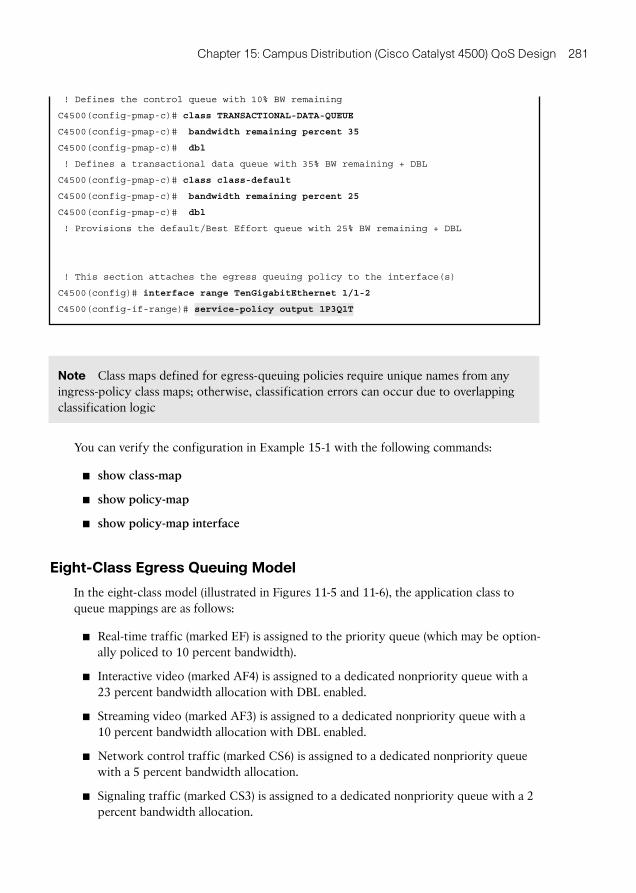
! Defines the control queue with 10% BW remaining
C4500(config-pmap-c)# class TRANSACTIONAL-DATA-QUEUE
C4500(config-pmap-c)# bandwidth remaining percent 35
C4500(config-pmap-c)# dbl
! Defines a transactional data queue with 35% BW remaining + DBL
C4500(config-pmap-c)# class class-default
C4500(config-pmap-c)# bandwidth remaining percent 25
C4500(config-pmap-c)# dbl
! Provisions the default/Best Effort queue with 25% BW remaining + DBL
! This section attaches the egress queuing policy to the interface(s)
C4500(config)# interface range TenGigabitEthernet 1/1-2
C4500(config-if-range)# service-policy output 1P3Q1T
Note Class maps defined for egress-queuing policies require unique names from any ingress-policy class maps; otherwise, classification errors can occur due to overlapping classification logic
You can verify the configuration in Example 15-1 with the following commands:
show class-map
show policy-map
show policy-map interface
Eight-Class Egress Queuing Model
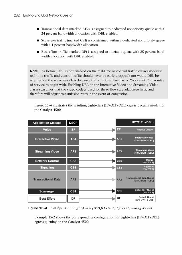
In the eight-class model (illustrated in Figures 11-5 and 11-6 ), the application class to queue mappings are as follows:
Real-time traffic (marked EF) is assigned to the priority queue (which may be option-ally policed to 10 percent bandwidth).
Interactive video (marked AF4) is assigned to a dedicated nonpriority queue with a 23 percent bandwidth allocation with DBL enabled.
Streaming video (marked AF3) is assigned to a dedicated nonpriority queue with a 10 percent bandwidth allocation with DBL enabled.
Network control traffic (marked CS6) is assigned to a dedicated nonpriority queue with a 5 percent bandwidth allocation.
Signaling traffic (marked CS3) is assigned to a dedicated nonpriority queue with a 2 percent bandwidth allocation.
282 End-to-End QoS Network Design
Transactional data (marked AF2) is assigned to dedicated nonpriority queue with a 24 percent bandwidth allocation with DBL enabled.
Scavenger traffic (marked CS1) is constrained within a dedicated nonpriority queue with a 1 percent bandwidth allocation.
Best-effort traffic (marked DF) is assigned to a default queue with 25 percent band-width allocation with DBL enabled.
Note As before, DBL is not enabled on the real-time or control traffic classes (because real-time traffic and control traffic should never be early dropped); nor would DBL be required on the scavenger class, because traffic in this class has no “good-faith” guarantee of service to begin with. Enabling DBL on the Interactive Video and Streaming Video classes assumes that the video codecs used for these flows are adaptive/elastic and therefore will adjust transmission rates in the event of congestion.
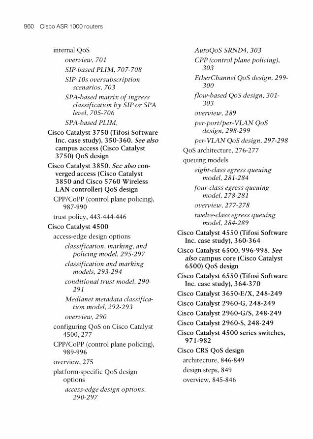
Figure 15-4 illustrates the resulting eight-class (1P7Q1T+DBL) egress queuing model for the Catalyst 4500.
T (+DBL)1Q7P1
ataD lanoitcasnarT
oediV evitcaretnI
ecioV
sessalC noitacilppA
regnevacS
troffE tseB
oediV gnimaertS
2FA
4FA
FE
PCSD
1SC
FD
3FA
Priority QueueFE
eueuQ tluafeD + DBL) RWB %52(
FD
eueuQ regnevacS )RWB %1(1SC
eueuQ ataD lanoitcasnarTR + DBL)WB %42(2FA
oediV gnimaertS3FA
oediV evitcaretnI4FA
gnilangiS 3SC gnilangiS )RWB %2(
3SC
lortnoC krowteN 6SC lortnoC6SC)RWB %5(
R + DBL)WB %23(
R + DBL)WB %10(
Figure 15-4 Catalyst 4500 Eight-Class (1P7Q1T+DBL) Egress Queuing Model
Example 15-2 shows the corresponding configuration for eight-class (1P7Q1T+DBL) egress queuing on the Catalyst 4500.
Chapter 15: Campus Distribution (Cisco Catalyst 4500) QoS Design 283
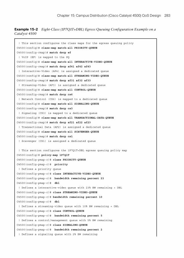
Example 15-2 Eight-Class (1P7Q1T+DBL) Egress Queuing Configuration Example on a Catalyst 4500
! This section configures the class maps for the egress queuing policy
C4500(config)# class-map match-all PRIORITY-QUEUE
C4500(config-cmap)# match dscp ef
! VoIP (EF) is mapped to the PQ
C4500(config)# class-map match-all INTERACTIVE-VIDEO-QUEUE
C4500(config-cmap)# match dscp af41 af42 af43
! Interactive-Video (AF4) is assigned a dedicated queue
C4500(config)# class-map match-all STREAMING-VIDEO-QUEUE
C4500(config-cmap)# match dscp af31 af32 af33
! Streaming-Video (AF3) is assigned a dedicated queue
C4500(config)# class-map match-all CONTROL-QUEUE
C4500(config-cmap)# match dscp cs6
! Network Control (CS6) is mapped to a dedicated queue
C4500(config)# class-map match-all SIGNALING-QUEUE
C4500(config-cmap)# match dscp cs3
! Signaling (CS3) is mapped to a dedicated queue
C4500(config)# class-map match-all TRANSACTIONAL-DATA-QUEUE
C4500(config-cmap)# match dscp af21 af22 af23
! Transactional Data (AF2) is assigned a dedicated queue
C4500(config)# class-map match-all SCAVENGER-QUEUE
C4500(config-cmap)# match dscp cs1
! Scavenger (CS1) is assigned a dedicated queue
! This section configures the 1P7Q1T+DBL egress queuing policy map
C4500(config)# policy-map 1P7Q1T
C4500(config-pmap-c)# class PRIORITY-QUEUE
C4500(config-pmap-c)# priority
! Defines a priority queue
C4500(config-pmap-c)# class INTERACTIVE-VIDEO-QUEUE
C4500(config-pmap-c)# bandwidth remaining percent 23
C4500(config-pmap-c)# dbl
! Defines a interactive-video queue with 23% BW remaining + DBL
C4500(config-pmap-c)# class STREAMING-VIDEO-QUEUE
C4500(config-pmap-c)# bandwidth remaining percent 10
C4500(config-pmap-c)# dbl
! Defines a streaming-video queue with 10% BW remaining + DBL
C4500(config-pmap-c)# class CONTROL-QUEUE
C4500(config-pmap-c)# bandwidth remaining percent 5
! Defines a control/management queue with 5% BW remaining
C4500(config-pmap-c)# class SIGNALING-QUEUE
C4500(config-pmap-c)# bandwidth remaining percent 2
! Defines a signaling queue with 2% BW remaining
284 End-to-End QoS Network Design
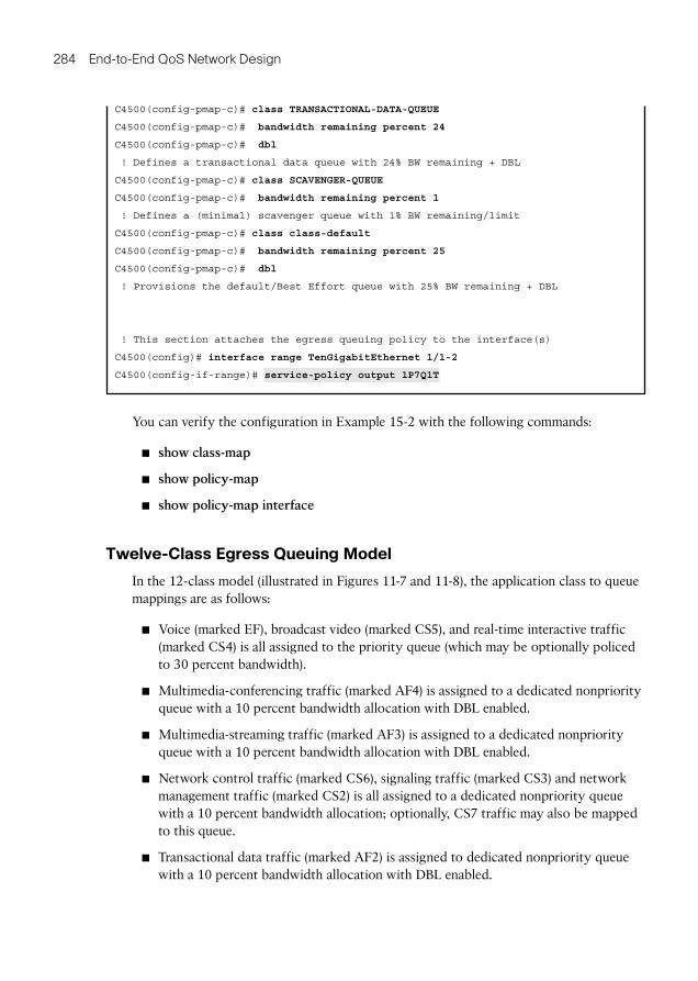
C4500(config-pmap-c)# class TRANSACTIONAL-DATA-QUEUE
C4500(config-pmap-c)# bandwidth remaining percent 24
C4500(config-pmap-c)# dbl
! Defines a transactional data queue with 24% BW remaining + DBL
C4500(config-pmap-c)# class SCAVENGER-QUEUE
C4500(config-pmap-c)# bandwidth remaining percent 1
! Defines a (minimal) scavenger queue with 1% BW remaining/limit
C4500(config-pmap-c)# class class-default
C4500(config-pmap-c)# bandwidth remaining percent 25
C4500(config-pmap-c)# dbl
! Provisions the default/Best Effort queue with 25% BW remaining + DBL
! This section attaches the egress queuing policy to the interface(s)
C4500(config)# interface range TenGigabitEthernet 1/1-2
C4500(config-if-range)# service-policy output 1P7Q1T
You can verify the configuration in Example 15-2 with the following commands:
show class-map
show policy-map
show policy-map interface
Twelve-Class Egress Queuing Model
In the 12-class model (illustrated in Figures 11-7 and 11-8 ), the application class to queue mappings are as follows:
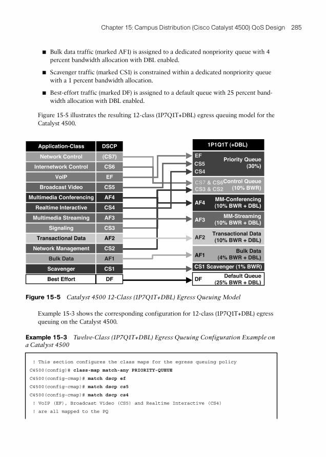
Voice (marked EF), broadcast video (marked CS5), and real-time interactive traffic (marked CS4) is all assigned to the priority queue (which may be optionally policed to 30 percent bandwidth).
Multimedia-conferencing traffic (marked AF4) is assigned to a dedicated nonpriority queue with a 10 percent bandwidth allocation with DBL enabled.
Multimedia-streaming traffic (marked AF3) is assigned to a dedicated nonpriority queue with a 10 percent bandwidth allocation with DBL enabled.
Network control traffic (marked CS6), signaling traffic (marked CS3) and network management traffic (marked CS2) is all assigned to a dedicated nonpriority queue with a 10 percent bandwidth allocation; optionally, CS7 traffic may also be mapped to this queue.
Transactional data traffic (marked AF2) is assigned to dedicated nonpriority queue with a 10 percent bandwidth allocation with DBL enabled.
Chapter 15: Campus Distribution (Cisco Catalyst 4500) QoS Design 285
Bulk data traffic (marked AF1) is assigned to a dedicated nonpriority queue with 4 percent bandwidth allocation with DBL enabled.
Scavenger traffic (marked CS1) is constrained within a dedicated nonpriority queue with a 1 percent bandwidth allocation.
Best-effort traffic (marked DF) is assigned to a default queue with 25 percent band-width allocation with DBL enabled.
Figure 15-5 illustrates the resulting 12-class (1P7Q1T+DBL) egress queuing model for the Catalyst 4500.
1P1Q1T (+DBL)
Priority Queue(30%)
CS7
EF
CS4
Network Management
Signaling
Realtime Interactive
Transactional Data
Multimedia Conferencing
Bulk Data
AF2
CS3
CS4
AF4
CS2
AF1
Scavenger CS1
Best Effort DF
Multimedia Streaming AF3
Broadcast Video
VoIP
Application-Class
CS5
EF
Internetwork Control CS6
DSCP
Network Control (CS7)CS5
Control Queue(10% BWR)
MM-Conferencing(10% BWR + DBL)
MM-Streaming(10% BWR + DBL)
Transactional Data(10% BWR + DBL)
Bulk Data(4% BWR + DBL)
Default Queue(25% BWR + DBL)
CS7 & CS6CS3 & CS2
DF
AF1
CS1 Scavenger (1% BWR)
AF4
AF3
AF2
Figure 15-5 Catalyst 4500 12-Class (1P7Q1T+DBL) Egress Queuing Model
Example 15-3 shows the corresponding configuration for 12-class (1P7Q1T+DBL) egress queuing on the Catalyst 4500.
Example 15-3 Twelve-Class (1P7Q1T+DBL) Egress Queuing Configuration Example on a Catalyst 4500
! This section configures the class maps for the egress queuing policy
C4500(config)# class-map match-any PRIORITY-QUEUE
C4500(config-cmap)# match dscp ef
C4500(config-cmap)# match dscp cs5
C4500(config-cmap)# match dscp cs4
! VoIP (EF), Broadcast Video (CS5) and Realtime Interactive (CS4)
! are all mapped to the PQ
286 End-to-End QoS Network Design
C4500(config)# class-map match-any CONTROL-MGMT-QUEUE
C4500(config-cmap)# match dscp cs7
C4500(config-cmap)# match dscp cs6
C4500(config-cmap)# match dscp cs3
C4500(config-cmap)# match dscp cs2
! Network Control (CS7), Internetwork Control (CS6),
! Signaling (CS3) and Management (CS2) are mapped
! to a Control/Management Queue
C4500(config)# class-map match-all MULTIMEDIA-CONFERENCING-QUEUE
C4500(config-cmap)# match dscp af41 af42 af43
! Multimedia Conferencing (AF4) is assigned a dedicated queue
C4500(config)# class-map match-all MULTIMEDIA-STREAMING-QUEUE
C4500(config-cmap)# match dscp af31 af32 af33
! Multimedia Streaming (AF3) is assigned a dedicated queue
C4500(config)# class-map match-all TRANSACTIONAL-DATA-QUEUE
C4500(config-cmap)# match dscp af21 af22 af23
! Transactional Data (AF2) is assigned a dedicated queue
C4500(config)# class-map match-all BULK-DATA-QUEUE
C4500(config-cmap)# match dscp af11 af12 af13
! Bulk Data (AF1) is assigned a dedicated queue
C4500(config)# class-map match-all SCAVENGER-QUEUE
C4500(config-cmap)# match dscp cs1
! Scavenger (CS1) is assigned a dedicated queue
! This section configures the 1P7Q1T+DBL egress queuing policy map
C4500(config)# policy-map 1P7Q1T
C4500(config-pmap-c)# class PRIORITY-QUEUE
C4500(config-pmap-c)# priority
! Defines a priority queue
C4500(config-pmap-c)# class CONTROL-MGMT-QUEUE
C4500(config-pmap-c)# bandwidth remaining percent 10
! Defines a control/management queue with 10% BW remaining
C4500(config-pmap-c)# class MULTIMEDIA-CONFERENCING-QUEUE
C4500(config-pmap-c)# bandwidth remaining percent 10
C4500(config-pmap-c)# dbl
! Defines a multimedia conferencing queue with 10% BW remaining + DBL
C4500(config-pmap-c)# class MULTIMEDIA-STREAMING-QUEUE
C4500(config-pmap-c)# bandwidth remaining percent 10
C4500(config-pmap-c)# dbl
! Defines a multimedia streaming queue with 10% BW remaining + DBL
C4500(config-pmap-c)# class TRANSACTIONAL-DATA-QUEUE
C4500(config-pmap-c)# bandwidth remaining percent 10
C4500(config-pmap-c)# dbl
Chapter 15: Campus Distribution (Cisco Catalyst 4500) QoS Design 287
! Defines a transactional data queue with 10% BW remaining + DBL
C4500(config-pmap-c)# class BULK-DATA-QUEUE
C4500(config-pmap-c)# bandwidth remaining percent 4
C4500(config-pmap-c)# dbl
! Defines a bulk data queue with 10% BW remaining + DBL
C4500(config-pmap-c)# class SCAVENGER-QUEUE
C4500(config-pmap-c)# bandwidth remaining percent 1
! Defines a (minimal) scavenger queue with 1% BW remaining/limit
C4500(config-pmap-c)# class class-default
C4500(config-pmap-c)# bandwidth remaining percent 25
C4500(config-pmap-c)# dbl
! Provisions the default/Best Effort queue with 25% BW remaining + DBL
! This section attaches the egress queuing policy to the interface(s)
C4500(config)# interface range TenGigabitEthernet 1/1-2
C4500(config-if-range)# service-policy output 1P7Q1T
You can verify the configuration in Example 15-3 with the following commands:
show class-map
show policy-map
show policy-map interface (as shown in Example 15-4 )
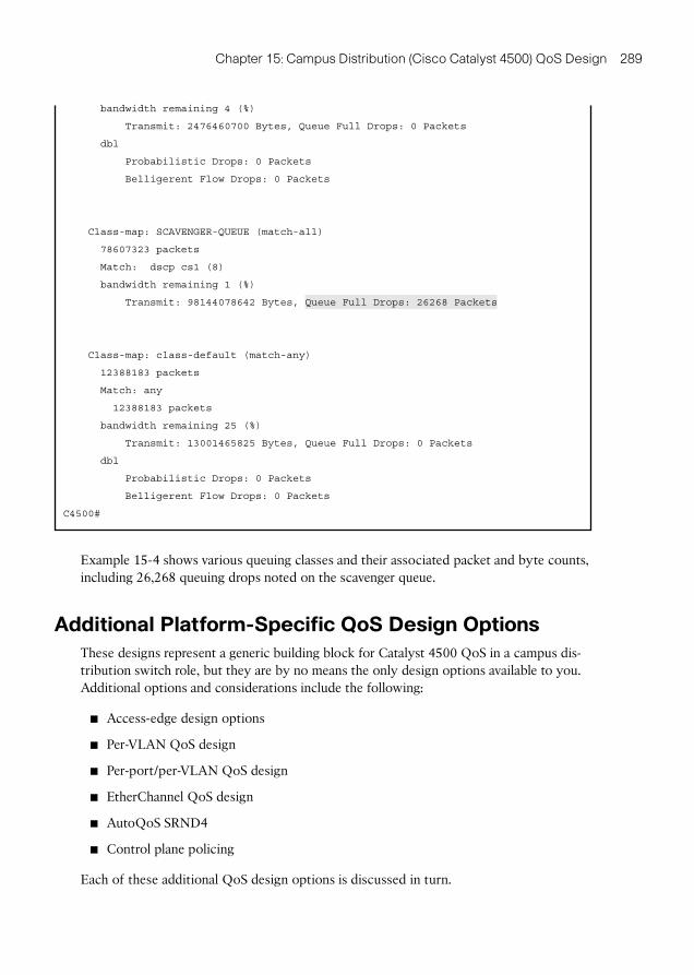
Example 15-4 Verifying Queuing Policies on a Catalyst 4500: show policy-map interface
C4500# show policy-map interface TenGigabitEthernet 1/1
TenGigabitEthernet1/1
Service-policy output: 1P7Q1T
Class-map: PRIORITY-QUEUE (match-any)
102598 packets
Match: dscp ef (46)
102598 packets
Match: dscp cs5 (40)
0 packets
Match: dscp cs4 (32)
0 packets
priority queue:
Transmit: 22782306 Bytes, Queue Full Drops: 0 Packets
Class-map: CONTROL-MGMT-QUEUE (match-any)
24847 packets
288 End-to-End QoS Network Design
Match: dscp cs7 (56)
0 packets
Match: dscp cs6 (48)
0 packets
Match: dscp cs3 (24)
24847 packets
Match: dscp cs2 (16)
0 packets
bandwidth remaining 10 (%)
Transmit: 24909844 Bytes, Queue Full Drops: 0 Packets
Class-map: MULTIMEDIA-CONFERENCING-QUEUE (match-all)
22280511 packets
Match: dscp af41 (34) af42 (36) af43 (38)
bandwidth remaining 10 (%)
Transmit: 4002626800 Bytes, Queue Full Drops: 0 Packets
dbl
Probabilistic Drops: 0 Packets
Belligerent Flow Drops: 0 Packets
Class-map: MULTIMEDIA-STREAMING-QUEUE (match-all)
0 packets
Match: dscp af31 (26) af32 (28) af33 (30)
bandwidth remaining 10 (%)
Transmit: 0 Bytes, Queue Full Drops: 0 Packets
dbl
Probabilistic Drops: 0 Packets
Belligerent Flow Drops: 0 Packets
Class-map: TRANSACTIONAL-DATA-QUEUE (match-all)
235852 packets
Match: dscp af21 (18) af22 (20) af23 (22)
bandwidth remaining 10 (%)
Transmit: 247591260 Bytes, Queue Full Drops: 0 Packets
dbl
Probabilistic Drops: 0 Packets
Belligerent Flow Drops: 0 Packets
Class-map: BULK-DATA-QUEUE (match-all)
2359020 packets
Match: dscp af11 (10) af12 (12) af13 (14)
Chapter 15: Campus Distribution (Cisco Catalyst 4500) QoS Design 289
bandwidth remaining 4 (%)
Transmit: 2476460700 Bytes, Queue Full Drops: 0 Packets
dbl
Probabilistic Drops: 0 Packets
Belligerent Flow Drops: 0 Packets
Class-map: SCAVENGER-QUEUE (match-all)
78607323 packets
Match: dscp cs1 (8)
bandwidth remaining 1 (%)
Transmit: 98144078642 Bytes, Queue Full Drops: 26268 Packets
Class-map: class-default (match-any)
12388183 packets
Match: any
12388183 packets
bandwidth remaining 25 (%)
Transmit: 13001465825 Bytes, Queue Full Drops: 0 Packets
dbl
Probabilistic Drops: 0 Packets
Belligerent Flow Drops: 0 Packets
C4500#
Example 15-4 shows various queuing classes and their associated packet and byte counts, including 26,268 queuing drops noted on the scavenger queue.
Additional Platform-Specific QoS Design Options
These designs represent a generic building block for Catalyst 4500 QoS in a campus dis-tribution switch role, but they are by no means the only design options available to you. Additional options and considerations include the following:
Access-edge design options
Per-VLAN QoS design
Per-port/per-VLAN QoS design
EtherChannel QoS design
AutoQoS SRND4
Control plane policing
Each of these additional QoS design options is discussed in turn.
290 End-to-End QoS Network Design
Access-Edge Design Options
This chapter has focused on QoS designs for the Catalyst 4500 in the role of a campus distribution switch (which are generally equivalent to the QoS designs required were it serving in the role of a campus core switch). However, the Catalyst 4500 can also be deployed as a campus access switch. Therefore, a few additional design options would apply in such a role, including the following access-edge models:
Conditional Trust Model
Classification and Marking Model
Classification, Marking, and Policing Model
Each of these access-edge design options will be discussed in turn.
Conditional Trust Model
As previously mentioned, MQC-based platforms trust at Layer 2 and Layer 3 by default and therefore do not require any explicit commands to perform such functions. Therefore, there are no equivalent commands to mls qos trust cos or mls qos trust dscp ( nor are any required).
However, there is a need to provide conditional trust functionality for all switch plat-forms that may be deployed in the role of an access switch. Hence, there is a correspond-ing command for conditional trust on the Catalyst 4500 (namely, qos trust device ).
At the time of this writing, the Catalyst 4500 supports conditional trust for the following devices:
Cisco IP phone via the cisco-phone keyword option
Cisco TelePresence systems via the cts keyword option
Cisco IP video surveillance cameras systems via the ip-camera keyword option
Cisco Digital Media Players via the media-player keyword option
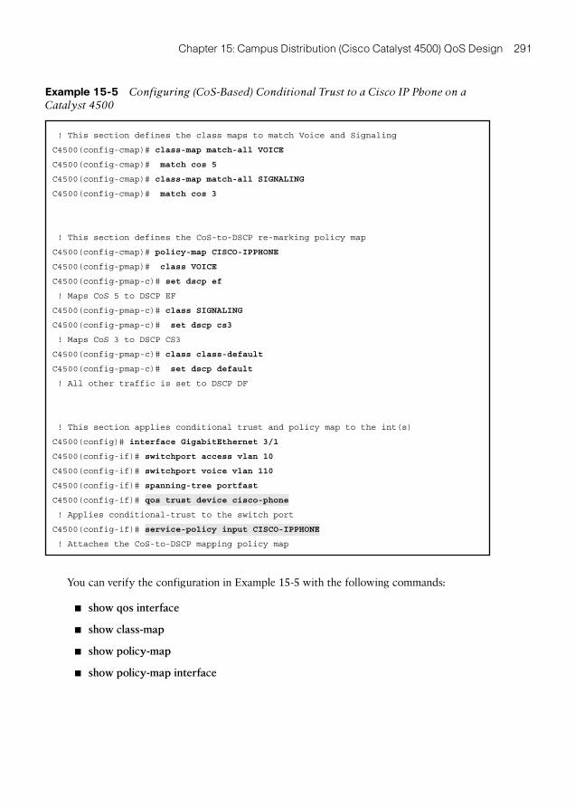
When extending conditional trust to Cisco IP phones, it is important to remember that these can only re-mark class of service (CoS) bits (on PC-generated traffic). Therefore, the Conditional Trust Model on the Catalyst 4500 requires a dynamic conditional trust pol-icy applied to the port in conjunction with a simple MQC policy that explicitly matches CoS 5 (for voice) and CoS 3 (for signaling) and marks the DSCP values of these packets to EF and CS3, respectively (essentially performing a CoS-to-DSCP mapping). Example 15-5 shows this conditional trust model for the Catalyst 4500.
Chapter 15: Campus Distribution (Cisco Catalyst 4500) QoS Design 291
Example 15-5 Configuring (CoS-Based) Conditional Trust to a Cisco IP Phone on a Catalyst 4500
! This section defines the class maps to match Voice and Signaling
C4500(config-cmap)# class-map match-all VOICE
C4500(config-cmap)# match cos 5
C4500(config-cmap)# class-map match-all SIGNALING
C4500(config-cmap)# match cos 3
! This section defines the CoS-to-DSCP re-marking policy map
C4500(config-cmap)# policy-map CISCO-IPPHONE
C4500(config-pmap)# class VOICE
C4500(config-pmap-c)# set dscp ef
! Maps CoS 5 to DSCP EF
C4500(config-pmap-c)# class SIGNALING
C4500(config-pmap-c)# set dscp cs3
! Maps CoS 3 to DSCP CS3
C4500(config-pmap-c)# class class-default
C4500(config-pmap-c)# set dscp default
! All other traffic is set to DSCP DF
! This section applies conditional trust and policy map to the int(s)
C4500(config)# interface GigabitEthernet 3/1
C4500(config-if)# switchport access vlan 10
C4500(config-if)# switchport voice vlan 110
C4500(config-if)# spanning-tree portfast
C4500(config-if)# qos trust device cisco-phone
! Applies conditional-trust to the switch port
C4500(config-if)# service-policy input CISCO-IPPHONE
! Attaches the CoS-to-DSCP mapping policy map
You can verify the configuration in Example 15-5 with the following commands:
show qos interface
show class-map
show policy-map
show policy-map interface
292 End-to-End QoS Network Design
Medianet Metadata Classification Model
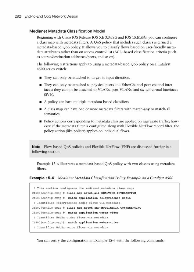
Beginning with Cisco IOS Release IOS XE 3.3.0SG and IOS 15.1(1)SG, you can configure a class map with metadata filters. A QoS policy that includes such classes is termed a metadata-based QoS policy. It allows you to classify flows based on user-friendly meta-data attributes rather than on access control list (ACL)-based classification criteria (such as source/destination addresses/ports, and so on).
The following restrictions apply to using a metadata-based QoS policy on a Catalyst 4500 series switch:
They can only be attached to target in input direction.
They can only be attached to physical ports and EtherChannel port channel inter-faces; they cannot be attached to VLANs, port VLANs, and switch virtual interfaces (SVIs).
A policy can have multiple metadata-based classifiers.
A class map can have one or more metadata filters with match-any or match-all semantics.
Policy actions corresponding to metadata class are applied on aggregate traffic; how-ever, if the metadata filter is configured along with Flexible NetFlow record filter, the policy action (like policer) applies on individual flows.
Note Flow-based QoS policies and Flexible NetFlow (FNF) are discussed further in a following section.
Example 15-6 illustrates a metadata-based QoS policy with two classes using metadata filters.
Example 15-6 Medianet Metadata Classification Policy Example on a Catalyst 4500
! This section configures the medianet metadata class maps
C4500(config-cmap)# class-map match-all REALTIME-INTERACTIVE
C4500(config-cmap)# match application telepresence-media
! Identifies TelePresence media flows via metadata
C4500(config-cmap)# class-map match-any MULTIMEDIA-CONFERENCING
C4500(config-cmap)# match application webex-video
! Identifies WebEx video flows via metadata
C4500(config-cmap)# match application webex-voice
! Identifies WebEx voice flows via metadata
You can verify the configuration in Example 15-6 with the following commands:
Chapter 15: Campus Distribution (Cisco Catalyst 4500) QoS Design 293
show class-map
show policy-map
show policy-map interface
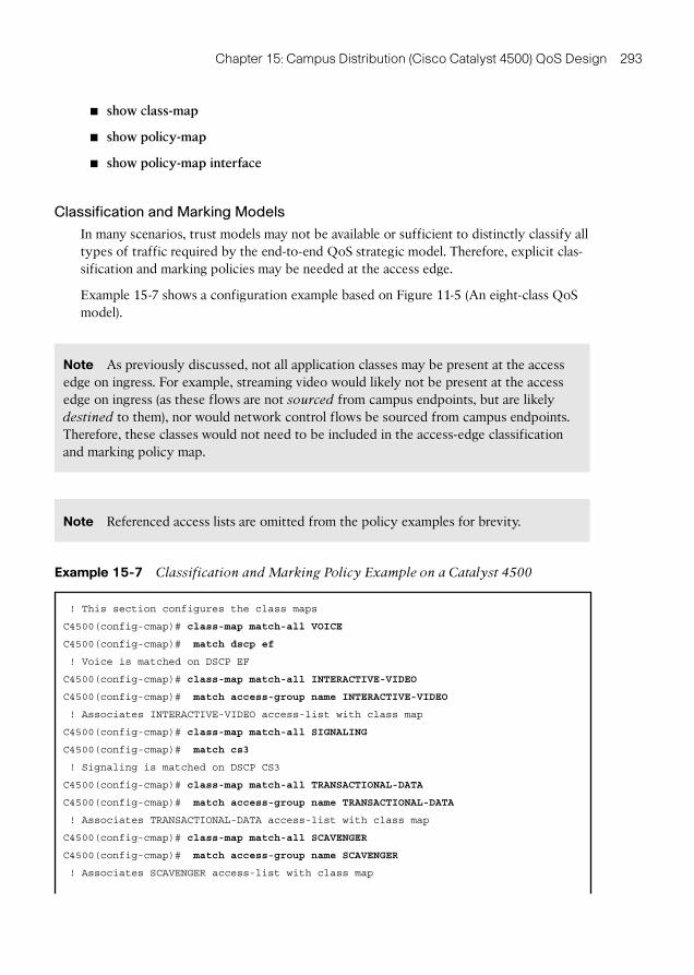
Classification and Marking Models
In many scenarios, trust models may not be available or sufficient to distinctly classify all types of traffic required by the end-to-end QoS strategic model. Therefore, explicit clas-sification and marking policies may be needed at the access edge.
Example 15-7 shows a configuration example based on Figure 11-5 (An eight-class QoS model).
Note As previously discussed, not all application classes may be present at the access edge on ingress. For example, streaming video would likely not be present at the access edge on ingress (as these flows are not sourced from campus endpoints, but are likely destined to them), nor would network control flows be sourced from campus endpoints. Therefore, these classes would not need to be included in the access-edge classification and marking policy map.
Note Referenced access lists are omitted from the policy examples for brevity.
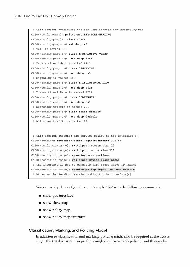
Example 15-7 Classification and Marking Policy Example on a Catalyst 4500
! This section configures the class maps
C4500(config-cmap)# class-map match-all VOICE
C4500(config-cmap)# match dscp ef
! Voice is matched on DSCP EF
C4500(config-cmap)# class-map match-all INTERACTIVE-VIDEO
C4500(config-cmap)# match access-group name INTERACTIVE-VIDEO
! Associates INTERACTIVE-VIDEO access-list with class map
C4500(config-cmap)# class-map match-all SIGNALING
C4500(config-cmap)# match cs3
! Signaling is matched on DSCP CS3
C4500(config-cmap)# class-map match-all TRANSACTIONAL-DATA
C4500(config-cmap)# match access-group name TRANSACTIONAL-DATA
! Associates TRANSACTIONAL-DATA access-list with class map
C4500(config-cmap)# class-map match-all SCAVENGER
C4500(config-cmap)# match access-group name SCAVENGER
! Associates SCAVENGER access-list with class map
294 End-to-End QoS Network Design
! This section configures the Per-Port ingress marking policy map
C4500(config-cmap)# policy-map PER-PORT-MARKING
C4500(config-pmap)# class VOICE
C4500(config-pmap-c)# set dscp ef
! VoIP is marked EF
C4500(config-pmap-c)# class INTERACTIVE-VIDEO
C4500(config-pmap-c)# set dscp af41
! Interactive-Video is marked AF41
C4500(config-pmap-c)# class SIGNALING
C4500(config-pmap-c)# set dscp cs3
! Signaling is marked CS3
C4500(config-pmap-c)# class TRANSACTIONAL-DATA
C4500(config-pmap-c)# set dscp af21
! Transactional Data is marked AF21
C4500(config-pmap-c)# class SCAVENGER
C4500(config-pmap-c)# set dscp cs1
! Scavenger traffic is marked CS1
C4500(config-pmap-c)# class class-default
C4500(config-pmap-c)# set dscp default
! All other traffic is marked DF
! This section attaches the service-policy to the interface(s)
C4500(config)# interface range GigabitEthernet 2/1-48
C4500(config-if-range)# switchport access vlan 10
C4500(config-if-range)# switchport voice vlan 110
C4500(config-if-range)# spanning-tree portfast
C4500(config-if-range)# qos trust device cisco-phone
! The interface is set to conditionally trust Cisco IP Phones
C4500(config-if-range)# service-policy input PER-PORT-MARKING
! Attaches the Per-Port Marking policy to the interface(s)
You can verify the configuration in Example 15-7 with the following commands:
show qos interface
show class-map
show policy-map
show policy-map interface
Classification, Marking, and Policing Model
In addition to classification and marking, policing might also be required at the access edge. The Catalyst 4500 can perform single-rate (two-color) policing and three-color
Chapter 15: Campus Distribution (Cisco Catalyst 4500) QoS Design 295
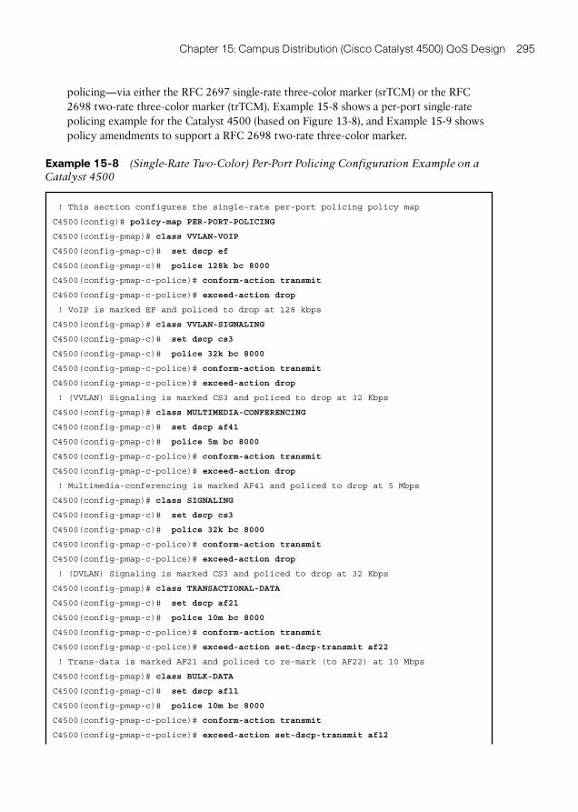
policing—via either the RFC 2697 single-rate three-color marker (srTCM) or the RFC 2698 two-rate three-color marker (trTCM). Example 15-8 shows a per-port single-rate policing example for the Catalyst 4500 (based on Figure 13-8 ), and Example 15-9 shows policy amendments to support a RFC 2698 two-rate three-color marker.
Example 15-8 (Single-Rate Two-Color) Per-Port Policing Configuration Example on a Catalyst 4500
! This section configures the single-rate per-port policing policy map
C4500(config)# policy-map PER-PORT-POLICING
C4500(config-pmap)# class VVLAN-VOIP
C4500(config-pmap-c)# set dscp ef
C4500(config-pmap-c)# police 128k bc 8000
C4500(config-pmap-c-police)# conform-action transmit
C4500(config-pmap-c-police)# exceed-action drop
! VoIP is marked EF and policed to drop at 128 kbps
C4500(config-pmap)# class VVLAN-SIGNALING
C4500(config-pmap-c)# set dscp cs3
C4500(config-pmap-c)# police 32k bc 8000
C4500(config-pmap-c-police)# conform-action transmit
C4500(config-pmap-c-police)# exceed-action drop
! (VVLAN) Signaling is marked CS3 and policed to drop at 32 Kbps
C4500(config-pmap)# class MULTIMEDIA-CONFERENCING
C4500(config-pmap-c)# set dscp af41
C4500(config-pmap-c)# police 5m bc 8000
C4500(config-pmap-c-police)# conform-action transmit
C4500(config-pmap-c-police)# exceed-action drop
! Multimedia-conferencing is marked AF41 and policed to drop at 5 Mbps
C4500(config-pmap)# class SIGNALING
C4500(config-pmap-c)# set dscp cs3
C4500(config-pmap-c)# police 32k bc 8000
C4500(config-pmap-c-police)# conform-action transmit
C4500(config-pmap-c-police)# exceed-action drop
! (DVLAN) Signaling is marked CS3 and policed to drop at 32 Kbps
C4500(config-pmap)# class TRANSACTIONAL-DATA
C4500(config-pmap-c)# set dscp af21
C4500(config-pmap-c)# police 10m bc 8000
C4500(config-pmap-c-police)# conform-action transmit
C4500(config-pmap-c-police)# exceed-action set-dscp-transmit af22
! Trans-data is marked AF21 and policed to re-mark (to AF22) at 10 Mbps
C4500(config-pmap)# class BULK-DATA
C4500(config-pmap-c)# set dscp af11
C4500(config-pmap-c)# police 10m bc 8000
C4500(config-pmap-c-police)# conform-action transmit
C4500(config-pmap-c-police)# exceed-action set-dscp-transmit af12
296 End-to-End QoS Network Design
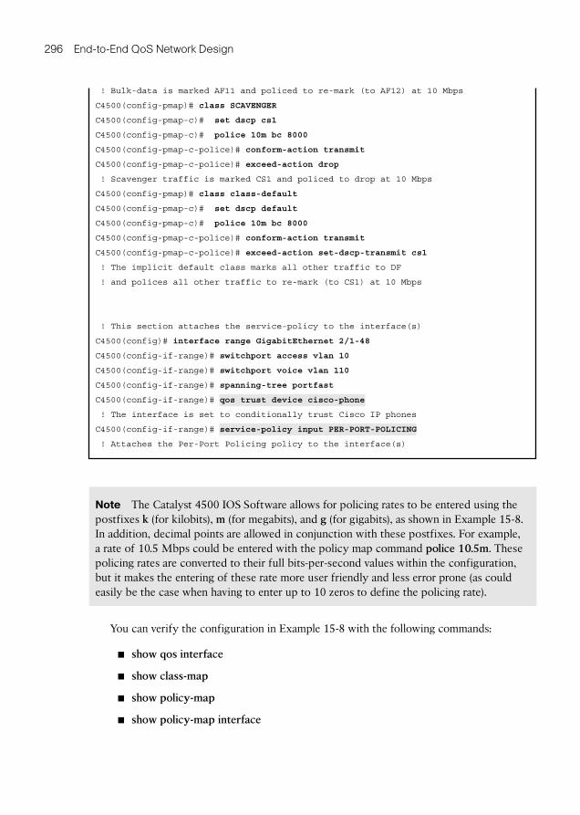
! Bulk-data is marked AF11 and policed to re-mark (to AF12) at 10 Mbps
C4500(config-pmap)# class SCAVENGER
C4500(config-pmap-c)# set dscp cs1
C4500(config-pmap-c)# police 10m bc 8000
C4500(config-pmap-c-police)# conform-action transmit
C4500(config-pmap-c-police)# exceed-action drop
! Scavenger traffic is marked CS1 and policed to drop at 10 Mbps
C4500(config-pmap)# class class-default
C4500(config-pmap-c)# set dscp default
C4500(config-pmap-c)# police 10m bc 8000
C4500(config-pmap-c-police)# conform-action transmit
C4500(config-pmap-c-police)# exceed-action set-dscp-transmit cs1
! The implicit default class marks all other traffic to DF
! and polices all other traffic to re-mark (to CS1) at 10 Mbps
! This section attaches the service-policy to the interface(s)
C4500(config)# interface range GigabitEthernet 2/1-48
C4500(config-if-range)# switchport access vlan 10
C4500(config-if-range)# switchport voice vlan 110
C4500(config-if-range)# spanning-tree portfast
C4500(config-if-range)# qos trust device cisco-phone
! The interface is set to conditionally trust Cisco IP phones
C4500(config-if-range)# service-policy input PER-PORT-POLICING
! Attaches the Per-Port Policing policy to the interface(s)
Note The Catalyst 4500 IOS Software allows for policing rates to be entered using the postfixes k (for kilobits), m (for megabits), and g (for gigabits), as shown in Example 15-8 . In addition, decimal points are allowed in conjunction with these postfixes. For example, a rate of 10.5 Mbps could be entered with the policy map command police 10.5m . These policing rates are converted to their full bits-per-second values within the configuration, but it makes the entering of these rate more user friendly and less error prone (as could easily be the case when having to enter up to 10 zeros to define the policing rate).
You can verify the configuration in Example 15-8 with the following commands:
show qos interface
show class-map
show policy-map
show policy-map interface
Chapter 15: Campus Distribution (Cisco Catalyst 4500) QoS Design 297
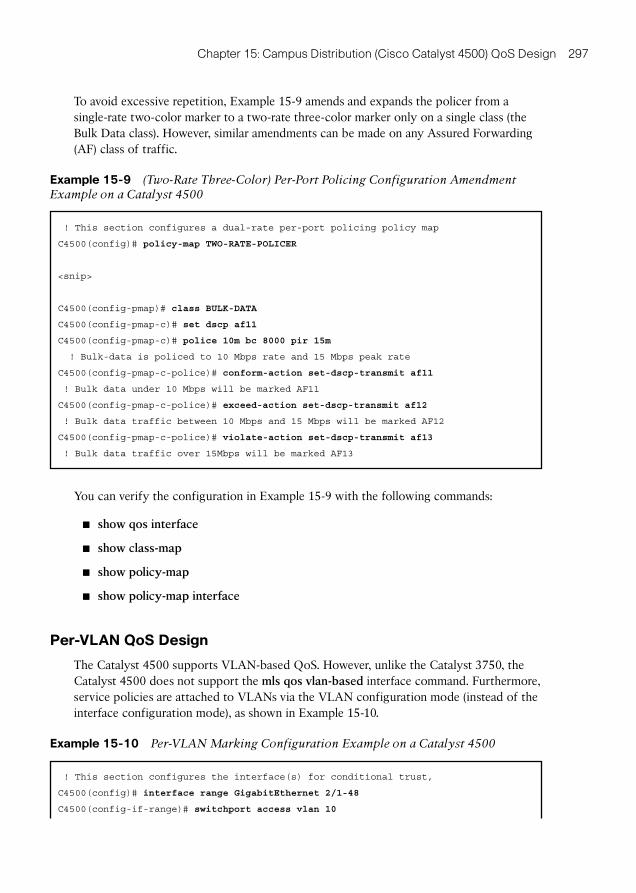
To avoid excessive repetition, Example 15-9 amends and expands the policer from a single-rate two-color marker to a two-rate three-color marker only on a single class (the Bulk Data class). However, similar amendments can be made on any Assured Forwarding (AF) class of traffic.
Example 15-9 (Two-Rate Three-Color) Per-Port Policing Configuration Amendment Example on a Catalyst 4500
! This section configures a dual-rate per-port policing policy map
C4500(config)# policy-map TWO-RATE-POLICER
<snip>
C4500(config-pmap)# class BULK-DATA
C4500(config-pmap-c)# set dscp af11
C4500(config-pmap-c)# police 10m bc 8000 pir 15m
! Bulk-data is policed to 10 Mbps rate and 15 Mbps peak rate
C4500(config-pmap-c-police)# conform-action set-dscp-transmit af11
! Bulk data under 10 Mbps will be marked AF11
C4500(config-pmap-c-police)# exceed-action set-dscp-transmit af12
! Bulk data traffic between 10 Mbps and 15 Mbps will be marked AF12
C4500(config-pmap-c-police)# violate-action set-dscp-transmit af13
! Bulk data traffic over 15Mbps will be marked AF13
You can verify the configuration in Example 15-9 with the following commands:
show qos interface
show class-map
show policy-map
show policy-map interface
Per-VLAN QoS Design
The Catalyst 4500 supports VLAN-based QoS. However, unlike the Catalyst 3750, the Catalyst 4500 does not support the mls qos vlan-based interface command. Furthermore, service policies are attached to VLANs via the VLAN configuration mode (instead of the interface configuration mode), as shown in Example 15-10 .
Example 15-10 Per-VLAN Marking Configuration Example on a Catalyst 4500
! This section configures the interface(s) for conditional trust,
C4500(config)# interface range GigabitEthernet 2/1-48
C4500(config-if-range)# switchport access vlan 10
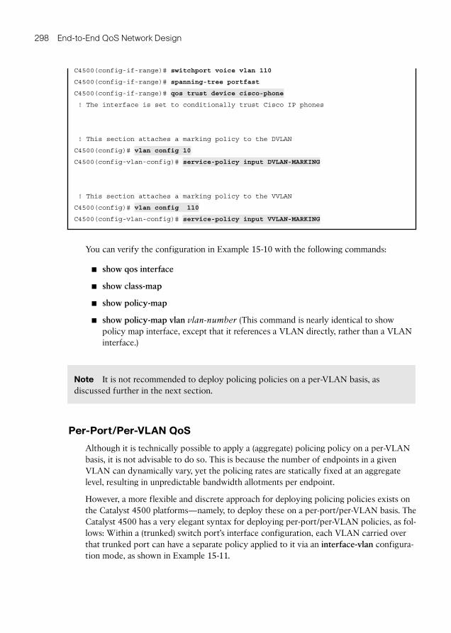
298 End-to-End QoS Network Design
C4500(config-if-range)# switchport voice vlan 110
C4500(config-if-range)# spanning-tree portfast
C4500(config-if-range)# qos trust device cisco-phone
! The interface is set to conditionally trust Cisco IP phones
! This section attaches a marking policy to the DVLAN
C4500(config)# vlan config 10
C4500(config-vlan-config)# service-policy input DVLAN-MARKING
! This section attaches a marking policy to the VVLAN
C4500(config)# vlan config 110
C4500(config-vlan-config)# service-policy input VVLAN-MARKING
You can verify the configuration in Example 15-10 with the following commands:
show qos interface
show class-map
show policy-map
show policy-map vlan vlan-number (This command is nearly identical to show policy map interface, except that it references a VLAN directly, rather than a VLAN interface.)
Note It is not recommended to deploy policing policies on a per-VLAN basis, as discussed further in the next section.
Per-Port/Per-VLAN QoS
Although it is technically possible to apply a (aggregate) policing policy on a per-VLAN basis, it is not advisable to do so. This is because the number of endpoints in a given VLAN can dynamically vary, yet the policing rates are statically fixed at an aggregate level, resulting in unpredictable bandwidth allotments per endpoint.
However, a more flexible and discrete approach for deploying policing policies exists on the Catalyst 4500 platforms—namely, to deploy these on a per-port/per-VLAN basis. The Catalyst 4500 has a very elegant syntax for deploying per-port/per-VLAN policies, as fol-lows: Within a (trunked) switch port’s interface configuration, each VLAN carried over that trunked port can have a separate policy applied to it via an interface-vlan configura-tion mode, as shown in Example 15-11 .
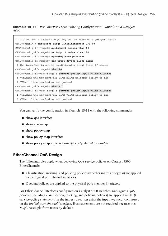
Chapter 15: Campus Distribution (Cisco Catalyst 4500) QoS Design 299
Example 15-11 Per-Port/Per-VLAN Policing Configuration Example on a Catalyst 4500
! This section attaches the policy to the VLANs on a per-port basis
C4500(config)# interface range GigabitEthernet 2/1-48
C4500(config-if-range)# switchport access vlan 10
C4500(config-if-range)# switchport voice vlan 110
C4500(config-if-range)# spanning-tree portfast
C4500(config-if-range)# qos trust device cisco-phone
! The interface is set to conditionally trust Cisco IP phones
C4500(config-if-range)# vlan 10
C4500(config-if-vlan-range)# service-policy input DVLAN-POLICERS
! Attaches the per-port/per-VLAN DVLAN policing policy to the
! DVLAN of the trunked switch port(s)
C4500(config-if-range)# vlan 110
C4500(config-if-vlan-range)# service-policy input VVLAN-POLICERS
! Attaches the per-port/per-VLAN VVLAN policing policy to the
! VVLAN of the trunked switch port(s)
You can verify the configuration in Example 15-11 with the following commands:
show qos interface
show class-map
show policy-map
show policy-map interface
show policy-map interface interface x/ y vlan vlan-number
EtherChannel QoS Design
The following rules apply when deploying QoS service policies on Catalyst 4500 EtherChannels:
Classification, marking, and policing policies (whether ingress or egress) are applied to the logical port channel interfaces.
Queuing policies are applied to the physical port-member interfaces.
For EtherChannel interfaces configured on Catalyst 4500 switches, the ingress QoS
policies (including classification, marking, and policing policies) are applied via MQC service-policy statements (in the ingress direction using the input keyword) configured on the logical port channel interface . Trust statements are not required because this MQC-based platform trusts by default.
300 End-to-End QoS Network Design
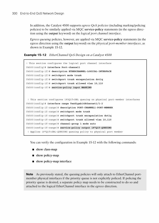
In addition, the Catalyst 4500 supports egress QoS policies (including marking/policing policies) to be similarly applied via MQC service-policy statements (in the egress direc-tion using the output keyword) on the logical port channel interface .
Egress queuing policies, however, are applied via MQC service-policy statements (in the egress direction using the output keyword) on the physical port-member interfaces , as shown in Example 15-12 .
Example 15-12 EtherChannel QoS Design on a Catalyst 4500
! This section configures the logical port channel interface
C4500(config)# interface Port-channel1
C4500(config-if)# description ETHERCHANNEL-LOGICAL-INTERFACE
C4500(config-if)# switchport mode trunk
C4500(config-if)# switchport trunk encapsulation dot1q
C4500(config-if)# switchport trunk allowed vlan 10,110
C4500(config-if)# service-policy input MARKING
! This section configures 1P3Q1T+DBL queuing on physical port-member interfaces
C4500(config)# interface range TenGigabitEthernet1/1-2
C4500(config-if-range)# description PORT-CHANNEL1-PORT-MEMBER
C4500(config-if-range)# switchport mode trunk
C4500(config-if-range)# switchport trunk encapsulation dot1q
C4500(config-if-range)# switchport trunk allowed vlan 10,110
C4500(config-if-range)# channel-group 1 mode auto
C4500(config-if-range)# service-policy output 1P7Q1T-QUEUING
! Applies 1P7Q1T+DBL-QUEUING queuing policy to physical port member
You can verify the configuration in Example 15-12 with the following commands:
show class-map
show policy-map
show policy-map interface
Note As previously stated, the queuing policies will only attach to EtherChannel port-member physical interfaces if the priority queue is not explicitly policed. If policing the priority queue is desired, a separate policy map needs to be constructed to do so and attached to the logical EtherChannel interface in the egress direction.
Chapter 15: Campus Distribution (Cisco Catalyst 4500) QoS Design 301
Flow-Based QoS
Flow-based QoS enables microflow policing and marking capability to dynamically learn traffic flows, providing the capability to police every unique flow to an individual rate. Flow-based QoS is available on a Catalyst 4500 series switch with the built-in NetFlow hardware support. It can be applied to ingress traffic on both switched and routed inter-faces with flow masks defined using Flexible NetFlow (FNF). Flow-based QoS is typi-cally used in environments where per-user, granular rate limiting is required. Flow-based QoS is also referred to as user-based rate limiting (UBRL).
A flow is defined as a stream of packets having the same properties as those defined by the key fields in the FNF flow record. A new flow is created when the value of data in packet’s key fields is unique with respect to the flows that already exist.
A flow-based QoS policy is possesses one or more class maps matching on a FNF flow record. Such a class map must be configured as match-all to match all the match criteria specified in the class map. When a flow-based QoS policy is attached to a QoS target, ingress traffic on the target is first classified based on the classification rules specified in the class map. If the classifier has an FNF flow record, the key fields specified in the FNF flow record are applied on the classified traffic to create flows provided the flow does not already exist. The corresponding policy actions (policing and marking) are then applied to these individual flows. Flow-based policers (termed microflow policers) rate limit each unique flow. Flows are dynamically created and inactive flows are periodically aged out.
Flow-based QoS policy can be applied on a per-port basis, per-port/per-VLAN basis, or on an EtherChannel port channel interface (but only in the ingress direction). Therefore, flow-based QoS may be deployed at either the access layer or distribution layer (wherever UBRL may be of value).
Note that flow-based policies will apply to all flows matched within a given class. For example, if a flow-based policer is applied to the default class and attached to port or VLAN, all flows originating from that port or VLAN (respectively) will be subject to the policer. If this is not to be the intent, additional classification is recommended and the flow-based policer should be more selectively applied.
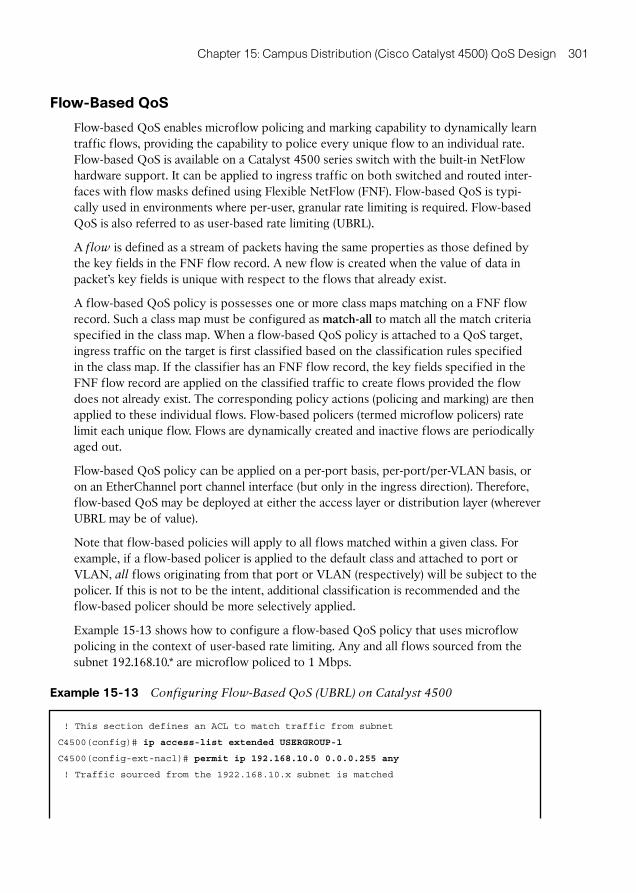
Example 15-13 shows how to configure a flow-based QoS policy that uses microflow policing in the context of user-based rate limiting. Any and all flows sourced from the subnet 192.168.10.* are microflow policed to 1 Mbps.
Example 15-13 Configuring Flow-Based QoS (UBRL) on Catalyst 4500
! This section defines an ACL to match traffic from subnet
C4500(config)# ip access-list extended USERGROUP-1
C4500(config-ext-nacl)# permit ip 192.168.10.0 0.0.0.255 any
! Traffic sourced from the 1922.168.10.x subnet is matched
302 End-to-End QoS Network Design
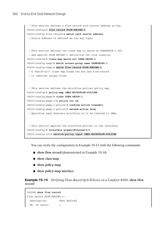
! This section defines a flow record with source address as key
C4500(config)# flow record FLOW-RECORD-1
C4500(config-flow-record)# match ipv4 source address
! Source address is defined as the key tuple
! This section defines the class map to match on USERGROUP-1 ACL
! and specify FLOW-RECORD-1 definition for flow creation
C4500(config)# class-map match-all USER-GROUP-1
C4500(config-cmap)# match access-group name USERGROUP-1
C4500(config-cmap)# match flow record FLOW-RECORD-1
! A "match-all" class map binds the ACL and flow-record
! to identify unique flows
! This section defines the microflow policer policy map
C4500(config)# policy-map 1MBS-MICROFLOW-POLICER
C4500(config-pmap)# class USER-GROUP-1
C4500(config-pmap-c)# police cir 1m
C4500(config-pmap-c-police)# conform-action transmit
C4500(config-pmap-c-police)# exceed-action drop
! Specifies each discrete microflow is to be limited to 1Mbs
! This section applies the microflow policer to the interface
C4500(config)# interface gigabitEthernet3/1
C4500(config-if)# service-policy input 1MBS-MICROFLOW-POLICER
You can verify the configuration in Example 15-13 with the following commands:
show flow record (demonstrated in Example 15-14 )
show class-map
show policy-map
show policy-map interface
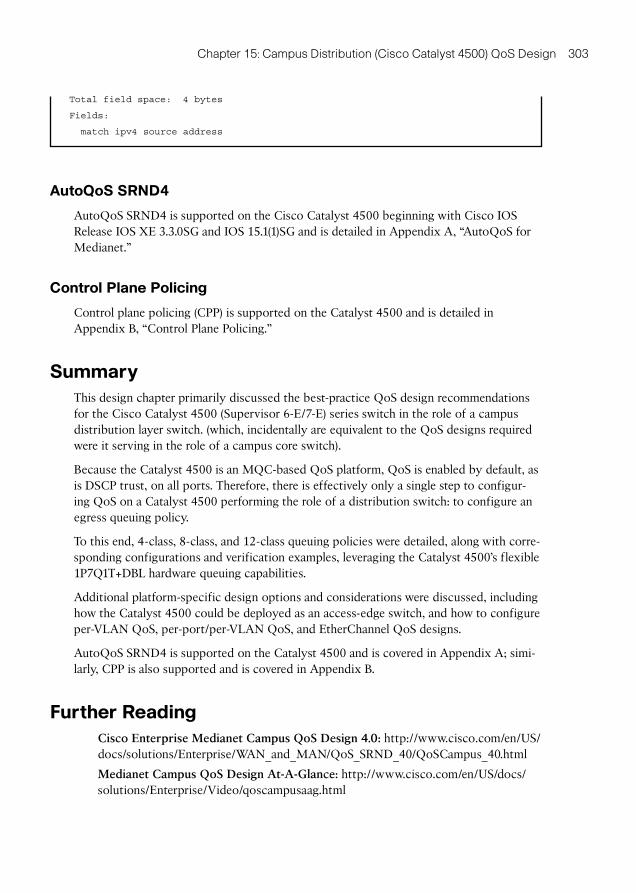
Example 15-14 Verifying Flow-Based QoS Policies on a Catalyst 4500: show flow record
C4500# show flow record
flow record FLOW-RECORD-1:
Description: User defined
No. of users: 1
Chapter 15: Campus Distribution (Cisco Catalyst 4500) QoS Design 303
Total field space: 4 bytes
Fields:
match ipv4 source address
AutoQoS SRND4
AutoQoS SRND4 is supported on the Cisco Catalyst 4500 beginning with Cisco IOS Release IOS XE 3.3.0SG and IOS 15.1(1)SG and is detailed in Appendix A , “AutoQoS for Medianet.”
Control Plane Policing
Control plane policing (CPP) is supported on the Catalyst 4500 and is detailed in Appendix B , “Control Plane Policing.”
Summary
This design chapter primarily discussed the best-practice QoS design recommendations for the Cisco Catalyst 4500 (Supervisor 6-E/7-E) series switch in the role of a campus distribution layer switch. (which, incidentally are equivalent to the QoS designs required were it serving in the role of a campus core switch).
Because the Catalyst 4500 is an MQC-based QoS platform, QoS is enabled by default, as is DSCP trust, on all ports. Therefore, there is effectively only a single step to configur-ing QoS on a Catalyst 4500 performing the role of a distribution switch: to configure an egress queuing policy.
To this end, 4-class, 8-class, and 12-class queuing policies were detailed, along with corre-sponding configurations and verification examples, leveraging the Catalyst 4500’s flexible 1P7Q1T+DBL hardware queuing capabilities.
Additional platform-specific design options and considerations were discussed, including how the Catalyst 4500 could be deployed as an access-edge switch, and how to configure per-VLAN QoS, per-port/per-VLAN QoS, and EtherChannel QoS designs.
AutoQoS SRND4 is supported on the Catalyst 4500 and is covered in Appendix A ; simi-larly, CPP is also supported and is covered in Appendix B .
Further Reading
Cisco Enterprise Medianet Campus QoS Design 4.0: http://www.cisco.com/en/US/docs/solutions/Enterprise/WAN_and_MAN/QoS_SRND_40/QoSCampus_40.html
Medianet Campus QoS Design At-A-Glance: http://www.cisco.com/en/US/docs/solutions/Enterprise/Video/qoscampusaag.html
304 End-to-End QoS Network Design
Medianet Catalyst 4500 QoS Design At-A-Glance: http://www.cisco.com/en/US/docs/solutions/Enterprise/Video/qoscampuscat4500aag.html
Cisco Catalyst 4500 Series Switch Software Configuration Guide, Release IOS XE 3.3.0SG and IOS 15.1(1)SG—QoS Configuration Guide: http://www.cisco.com/en/US/docs/switches/lan/catalyst4500/15.1/XE_330SG/configuration/guide/qos_mrg.html
Index
A
access/aggregation layer Nexus 5500/2000 QoS design (Tifosi Software Inc. case study), 659 - 666
access-edge design
campus core (Cisco Catalyst 6500) QoS design
classification, marking, and policing models, 335 - 340
classification and marking models, 332 - 335
conditional trust models, 330 - 332
overview, 330
Cisco Catalyst 4500
classification, marking, and policing model, 295 - 297
classification and marking models, 293 - 294
conditional trust model, 290 - 291
Medianet metadata classifica-tion model, 292 - 293
overview, 290
Tifosi Software, Inc. (case study)
Cisco IP phones and PCs (con-ditional trust and classifica-tion and marking), 482 - 485
Cisco TelePresence endpoints (conditional trust), 482
mobile wireless clients (dynam-ic policy with classification and marking), 489 - 490
wired access endpoints (DSCP trust), 481 - 482
wired printer endpoints (no trust), 481
wired queuing, 485 - 488
wireless queuing, 491 - 492
access layer uplink design (Tifosi Software Inc. case study), 359 - 360
ACs (access categories), 383 - 385
address-based classifications, 19 - 20
admission control, 14 , 100 - 101
advanced RSVP model with applica-tion ID, 729-733
AF (assured forwarding), 685
AF queue recommendations, 195
AIFSN (arbitration interframe spac-ing number), 385 - 386
954 AP
AP (access point), 4
application-based classifications, 19 - 20 , 739 - 743 , 745 - 747
application class expansion QoS strategies, 204 - 205
application-group-based classifica-tion model, 743 - 744 , 748
application policing server models, 578 - 580
application trends
control plane traffic, 180 - 182
data applications, 177 - 180
multimedia applications, 175 - 177
overview, 169 - 170
video applications, 171 - 175
voice, 170 - 171
architecture . See also specific archi-tectures
data center access/aggregation (Nexus 5500/2000) QoS design
overview, 562 - 564
QoS groups and system classes, 567 - 569
QoS policies supported by, 562 - 564
VOQ (virtual output queuing), 564 - 567
data center QoS design consider-ations and recommendations
big data (HPC/HTC/Grid) architectures, 501 - 502
high-performance trading data center architectures, 500 - 501
massively scalable data center architectures, 506
overview, 500
secure multitenant data center architectures, 505
virtualized multiservice data center architectures, 503 - 505
data center virtual access (Nexus 1000V) QoS design, 537 - 539
Medianet, 119 - 120
QoS, 14 - 16
service provider core (Cisco CRS) QoS design, 846 - 849
service provider edge (Cisco ASR 9000) QoS design, 810 - 814
ASR (Aggregation Services Routers), 190
assured forwarding (AF), 685
asymmetrical CoS/DSCP marking, 526
ATM (Asynchronous Transfer Mode), 3 , 38 - 39
ATM traffic shaping, 78
attribute-based classification model, 744 , 748 - 752
auto qos classify, 28
auto qos trust, 28
auto qos video, 28
auto qos voip, 28
Auto Smartports, 121 , 243
autodiscovery (data collection), 28
AutoQoS
marking, 54
Medianet
Cisco Catalyst 4500 series switches, 971 - 982
classify and police models, 958 - 963
overview, 953 - 955
1P3Q3T egress queuing mod-els, 969 - 971
1P1Q3T ingress queuing mod-els, 968 - 969
trust models, 955 - 956
best practice design principles 955
video models, 956 - 958
VoIP models, 963 - 968
overview, 25 - 28 , 121 - 122
SRND4
branch router (Cisco ISR G2) QoS design, 757
campus access (Cisco Catalyst 3750) QoS design, 274
Cisco Catalyst 4500, 303
WAN aggregator (Cisco ASR 1000) QoS design, 708, 733
VoIP, 27 , 242
AVC (application visibility control)
ASR 1000 routers, 137
building blocks, 140 - 159
Cisco wireless LAN routers, 137
FNF (Flexible NetFlow)
configuration, 149 - 152
key fields, 148 - 149
non-key fields, 148 - 149
overview, 147 - 148
performance considerations, 159 - 160
how it works, 138 - 140
Internet edge, 137
ISR G2 routers, 137
management and reporting
Insight Reporter, 153
overview, 152 - 153
NBAR2
MQC classification, 144 - 147
overview, 140 - 142
performance considerations, 159 - 160
protocol discovery, 142 - 144
overview, 136 - 137
performance considerations, 159 - 160
QoS controls
Internet edge, deploying AVC QoS controls at, 156 - 158
overview, 154
WAN edge, deploying AVC QoS controls at, 154 - 156
use cases, 136 - 137
WAN and branch QoS design con-siderations and recommenda-tions, 687
WAN edge, 137
wireless LAN controller (Cisco 5500) QoS design, 417 - 424
B
bandwidth
allocation, 14
changes in, 2
bandwidth reservation tools
admission control tools, 100 - 101
overview, 99 - 100
recommendations and guidelines, 108
RSVP
deployment models, 103 - 106
LLQ and, 106 - 107
overview, 101 - 102
proxy, 102 - 103
basic RSVP model, 726-729
behavioral model for QoS, 15
best effort data, 179
best practice design principles
classification and marking best prac-tices, 191 - 192
hardware versus software QoS best practices, 190
956 best practice design principles
overview, 189 - 190
policing and markdown best prac-tices, 192
queuing and dropping best practices
AF queue recommendations, 195
DF queue recommendations, 195
EF queue recommendations: the 33% LLQ rule, 193 - 195
overview, 192 - 193
scavenger class queue recom-mendations, 195 - 196
WRED recommendations, 197
big data (HPC/HTC/Grid) architec-tures, 501 - 502
bottom-up applications, 168
branch LAN edge, 693
branch router (Cisco ISR G2) QoS design
egress QoS models
eight-class model, 754
four-class model, 754
overview, 753
twelve-class model, 754 - 756
ingress QoS models
Medianet classification models, 738 - 744
NBAR2 classification models, 744 - 753
overview, 738
overview, 753 , 757
platform-specific QoS design options
AutoQoS SRND4, 757
control plane policing, 757
overview, 757
RSVP, 757
branch routers, 677 - 678
branch WAN edge, 693
broadcast streams, 165
broadcast video, 34 , 173 - 174
Bronze QoS profile for wireless LAN controller (Cisco 5500) QoS design, 400 - 408
buffer size, modifying ingress, 580 - 582
bulk data (high-throughput data), 178 - 179
business and application QoS require-ments
application trends
control plane traffic, 180 - 182
data applications, 177 - 180
multimedia applications, 175 - 177
overview, 169 - 170
video applications, 171 - 175
voice, 170 - 171
bottom-up applications, 168
BYOD (bring your own device), 167 - 168
global trends in networking, 164
high-definition media, 169
media content, increase in, 166 - 167
multimedia applications, conver-gence of media subcomponents within, 168 - 169
QoS standards evolution
overview, 183
RFC 2597 (clarification), 183 - 184
RFC 4594 (update draft), 185 - 187
RFC 5865 (proposed standard), 184 - 185
campus core 957
RFC 4594-based application class QoS recommendations, 182
social networking, appearance and effect on business networks of, 167
top-down deployments, 168
video applications, evolution of, 164 - 166
business catalysts for QoS reengi-neering (Tifosi Software Inc. case study), 216 - 217
BYOD (bring your own device), 167 - 168
C
C-Vision, 167
CAC (call admission control)
overview, 62 , 99 - 100
wireless LAN controller (Cisco 5500) QoS design
configuring, 414 - 415
overview, 413
campus access (Cisco Catalyst 3750) QoS design
Cisco Catalyst 3750 QoS architec-ture, 248 - 249
classification, marking, and policing models, 256 - 259
classification and marking models, 254 - 256
enabling QoS globally, 250
ingress QoS models, configuring, 250 - 259
overview, 247 - 248
platform-specific QoS design options
AutoQoS SRND4, 274
EtherChannel QoS design, 273
overview, 271
per-port/per-VLAN QoS design, 272 - 273
per-VLAN QoS design, 271 - 272
queuing models
egress queuing model, 265 - 271
ingress queuing model, 261 - 265
overview, 260 - 261
steps for, 249 - 271
trust models
conditional trust models, 253 - 254
overview, 251
trust CoS model, 251 - 252
trust DSCP model, 252
untrusted model, 251
campus AutoQoS, 241 - 243
campus CE ingress/internal QoS (ASR 1000), 788
campus core (Cisco Catalyst 6500) QoS design
access-edge design options
classification, marking, and policing models, 335 - 340
classification and marking models, 332 - 335
conditional trust models, 330 - 332
overview, 330
architecture, 306 - 308
overview, 305 - 306
platform-specific QoS design options
access-edge design options, 330 - 340
CPP (control plane policing), 344
958 campus core
EtherChannel QoS design, 343 - 344
microflow policing, 341 - 342
overview, 329 - 330
per-VLAN QoS design, 342 - 343
queuing models
eight-class (8Q4T ingress and 1P7Q4T egress) queuing models, 314 - 318
four-class (4Q4T ingress and 1P3Q4T egress) queuing models, 311 - 314
overview, 308 - 311
2P6Q4T ingress and egress queuing models, 328 - 329
twelve-class (8Q4T ingress and 1P7Q4T egress) queuing models, 318 - 328
steps for, 308
campus distribution (Cisco Catalyst 4500) QoS design
Cisco Catalyst 4500 QoS architec-ture, 276 - 277
configuring QoS on Cisco Catalyst 4500, 277
overview, 275
platform-specific QoS design options
access-edge design options, 290 - 297
AutoQoS SRND4, 303
CPP (control plane policing), 303
EtherChannel Qos design, 299 - 300
flow-based Qos design, 301 - 303
overview, 289
per-port/per-VLAN Qos design, 298 - 299
per-VLAN Qos design, 297 - 298
queuing models
eight-class egress queuing model, 281 - 284
four-class egress queuing model, 278 - 281
overview, 277 - 278
twelve-class egress queuing model, 284 - 289
campus port QoS roles
overview, 239
switch ports connecting to condi-tionally trusted endpoints, 240
switch ports connecting to network infrastructure, 241
switch ports connecting to trusted endpoints, 240
switch ports connecting to untrusted endpoints, 240
campus QoS design (Tifosi Software Inc. case study)
access layer uplink design, 359 - 360
access QoS design, 350 - 360
Catalyst 3750, 350 - 360
Catalyst 4550, 360 - 364
Catalyst 6550, 364 - 370
Cisco IP phones or PCs (conditional trust and classification and mark-ing), access-edge design for, 352 - 355
Cisco TelePresence endpoints (con-ditional trust), access-edge design for, 352
core layer (40GE) core-link design, 368 - 370
core layer (10GE) downlink design, 364 - 368
core QoS design, 364 - 370
Cisco ASR 1000 routers 959
distribution layer distribution-link/core-uplink ports, 362 - 364
distribution layer downlink ports, 360 - 362
distribution QoS design, 360 - 364
eight-class 1P3Q3T egress queuing design, 357 - 359
eight-class 1P1Q3T ingress queuing design, 355 - 357
overview, 347 - 350
printer endpoints, access-edge design for, 351
wireless access endpoints (DSCP Trust), access-edge design for, 351
campus QoS design considerations and recommendations
AutoQoS, 241 - 243
CoPP (control plane policing), 243 - 244
default QoS, 226
DSCP transparency, 231
EtherChannel QoS, 234 - 235
internal DSCP, 226 - 227
MLS versus MQC, 225 - 226
overview, 223 - 225
port-based QoS versus VLAN-based QoS versus per-port/per-VLAN QoS, 232 - 233
port QoS roles
overview, 239
switch ports connecting to con-ditionally trusted endpoints, 240
switch ports connecting to net-work infrastructure, 241
switch ports connecting to trusted endpoints, 240
switch ports connecting to untrusted endpoints, 240
QoS models
egress QoS models, 238 - 239
ingress QoS models, 235 - 237
overview, 235
trust boundaries, 230 - 231
trust states and operations, 227 - 230
CAPWAP (Control and Wireless Access Points), 40 , 389
CBWFQ (class-based weighted fair queuing), 87 - 89
scavenger CBWFQs, 691
WAN and branch QoS design con-siderations and recommenda-tions, 683
CE LAN edge, 788
CE routers (Tifosi Software Inc. case study)
internal QoS (Cisco ASR 1000), 863
LAN-edge QoS policies, 863
VPN-edge QoS policies, 863 - 866
CE VPN edge, 788
circuit-switched networks, 3
Cisco ASR 9000 QoS design
architecture, 810 - 814
MPLS DiffServ tunneling models
overview, 814 - 815
pipe mode MPLS DiffServ tun-neling, 826 - 834
short pipe mode MPLS DiffServ tunneling, 834 - 842
uniform mode MPLS DiffServ tunneling, 815 - 826
overview, 809
steps for, 814
Cisco ASR 1000 routers . See also WAN aggregator (Cisco ASR 1000) QoS design, 708, 733
AVC (application visibility control), 137
960 Cisco ASR 1000 routers
internal QoS
overview, 701
SIP-based PLIM, 707-708
SIP-10s oversubscription scenarios, 703
SPA-based matrix of ingress classification by SIP or SPA level, 705-706
SPA-based PLIM,
Cisco Catalyst 3750 (Tifosi Software Inc. case study), 350 - 360 . See also campus access (Cisco Catalyst 3750) QoS design
Cisco Catalyst 3850 . See also con-verged access (Cisco Catalyst 3850 and Cisco 5760 Wireless LAN controller) QoS design
CPP/CoPP (control plane policing), 987 - 990
trust policy, 443 - 444 - 446
Cisco Catalyst 4500
access-edge design options
classification, marking, and policing model, 295 - 297
classification and marking models, 293 - 294
conditional trust model, 290 - 291
Medianet metadata classifica-tion model, 292 - 293
overview, 290
configuring QoS on Cisco Catalyst 4500, 277
CPP/CoPP (control plane policing), 989 - 996
overview, 275
platform-specific QoS design options
access-edge design options, 290 - 297
AutoQoS SRND4, 303
CPP (control plane policing), 303
EtherChannel QoS design, 299 - 300
flow-based QoS design, 301 - 303
overview, 289
per-port/per-VLAN QoS design, 298 - 299
per-VLAN QoS design, 297 - 298
QoS architecture, 276 - 277
queuing models
eight-class egress queuing model, 281 - 284
four-class egress queuing model, 278 - 281
overview, 277 - 278
twelve-class egress queuing model, 284 - 289
Cisco Catalyst 4550 (Tifosi Software Inc. case study), 360 - 364
Cisco Catalyst 6500, 996 - 998 . See also campus core (Cisco Catalyst 6500) QoS design
Cisco Catalyst 6550 (Tifosi Software Inc. case study), 364 - 370
Cisco Catalyst 3650-E/X, 248 - 249
Cisco Catalyst 2960-G, 248 - 249
Cisco Catalyst 2960-G/S, 248 - 249
Cisco Catalyst 2960-S, 248 - 249
Cisco Catalyst 4500 series switches, 971 - 982
Cisco CRS QoS design
architecture, 846 - 849
design steps, 849
overview, 845 - 846
Cisco Nexus 1000V QoS Design 961
SP core CoS QoS models
eight-CoS SP core model, 857 - 860
four-CoS SP model, 850 - 854
overview, 849 - 850
six-CoS SP core model, 854 - 857
Cisco 5500 wireless LAN controllers
AVC (application visibility control), 417 - 424
Bronze QoS profile, 400 - 408
CAC (call admission control)
configuring, 414 - 415
overview, 413
downstream traffic, 425 - 429
EDCA, optimizing, 411 - 412
eight-class model design, 430 - 431
enforcement points, 398
four-class model design, 425 - 430
Gold QoS profile, 400 - 408
guest QoS profile, building, 408 - 410
Media Session (SIP) snooping, 416 - 417
overview, 397
Platinum QoS profile, 400 - 408
Silver QoS profile, 400 - 408
strategy, developing, 424 - 431
trust boundaries, 399 - 400
twelve-class model design, 431
upstream traffic, 429 - 430
VoIP applications, 410 - 413
WLAN QoS profiles, 400 - 408
WMM policy
enabling, 413 - 414
overview, 405 - 408
Cisco IP NGN (Next-Generation Network) carrier Ethernet, 774
Cisco IP phones or PCs (conditional trust and classification and mark-ing), access-edge design for, 352 - 355
Cisco ISE (Identity Services Engine), 495
Cisco ISR G2 QoS design, 738 - 739 , 744 - 745
Cisco Nexus 7000
F2/F2e-Series I/O modules
additional design options, 638 - 648
architecture, 623 - 625
default network QoS policy design, 625 - 629
FEX (Fabric Extender) QoS design, 638
overview, 630
QoS design steps, 625
queuing models, 630 - 637
fabric modules, 600
M2-Series I/O modules
additional design options, 638 - 648
architecture, 604 - 607
OTV (Overlay Transport Virtualization) edge device QoS design, 621 - 623
overview, 607
QoS design steps, 607
queuing models, 607 - 621
overview, 600 - 604
QoS policies supported by, 601 - 602
supervisor modules, 600
trust default behavior, 602 - 603
Cisco Nexus 2000 fabric extender QoS, 593 - 596
Cisco Nexus OS QoS framework, 519 - 520
Cisco Nexus 1000V (data center vir-tual access) QoS design
962 Cisco Nexus 1000V QoS Design
architecture, 537 - 539
configuration notes, 539 - 540
egress QoS models
eight-class queuing model, 556 - 558
four-class queuing model, 551 - 556
overview, 549 - 551
ingress QoS models
classification and marking, 544 - 547
overview, 541
server policing model, 547 - 549
trusted models, 541 - 544
overview, 535 - 537
statistics, monitoring QoS, 540
trust models
trusted server model, 541
untrusted server model, 541 - 544
VEM (virtual ethernet module), 537 - 539
VSM (virtual supervisor module), 537 - 539
Cisco TelePresence, 166 , 169 , 352
Cisco to RFC 4594 markings, map-ping, 42
Cisco Unified Communications Manager (CUCM), 103
Cisco Unified Wireless Networking (CUWN), 435 - 436
Cisco Visual Networking Index: Forecast and Methodology Report, 164
Cisco wireless LAN routers, 137
class-map command, 17
class maps
addressing information, 19 - 20 , 46
application-based classifications, 19 - 20
feature sequence, effects of, 52
logical or physical interface, 46
marking-based classifications, 19 - 20
MQC (modular QoS command-line) framework, 19 - 20
overview, 50 - 52
packet attributes, characteristics, or field values, 45
packet discard eligibility, 51
packet header markings, 45
ports, 46
protocols, 45 - 46
table map feature, mapping markings with, 52 - 53
ToS values, 51
tunnel ToS values, 51
classification
defined, 32
QoS, 14 - 15
classification, marking, and policing models
campus access (Cisco Catalyst 3750) QoS design, 256 - 259
campus core (Cisco Catalyst 6500) QoS design, 335 - 340
Cisco Catalyst 4500, 295 - 297
converged access (Cisco Catalyst 3850 and Cisco 5760 Wireless LAN controller) QoS design, 448 - 454
classification and marking
best practices, 191 - 192
campus access (Cisco Catalyst 3750) QoS design, 254 - 256
campus core (Cisco Catalyst 6500) QoS design, 332 - 335
Cisco Catalyst 4500, 293 - 294