CAMPUS CHILLED WATER SYSTEM STUDY -...
18
Campus Chiller System Study Eastern Washington University Page 1 CAMPUS CHILLED WATER SYSTEM STUDY SUBMITTED TO: SUBMITTED: June, 2009 BY: DUMAIS • ROMANS, INC. Consulting Mechanical Engineers N. 113 Conklin Road Veradale, Washington 99037 Phone: 509-893-9646 Fax: 509-893-9648 E-Mail: [email protected] [email protected]
Transcript of CAMPUS CHILLED WATER SYSTEM STUDY -...

Campus Chiller System Study
Eastern Washington University Page 1
CAMPUS CHILLED WATER SYSTEM STUDY
SUBMITTED TO:
SUBMITTED:
June, 2009
BY:
DUMAIS • ROMANS, INC. Consulting Mechanical Engineers
N. 113 Conklin Road Veradale, Washington 99037
Phone: 509-893-9646 Fax: 509-893-9648 E-Mail: [email protected] [email protected]
Campus Chiller System Study
Eastern Washington University Page 2
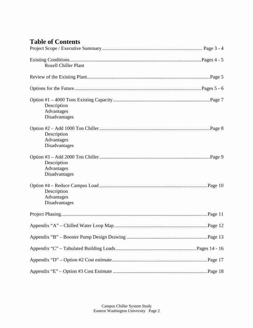
Table of Contents Project Scope / Executive Summary ................................................................................. Page 3 - 4 Existing Conditions .......................................................................................................... Pages 4 - 5
Rozell Chiller Plant
Review of the Existing Plant ................................................................................................... Page 5
Options for the Future ...................................................................................................... Pages 5 - 6
Option #1 – 4000 Tons Existing Capacity .............................................................................. Page 7 Description Advantages Disadvantages Option #2 – Add 1000 Ton Chiller ......................................................................................... Page 8 Description Advantages Disadvantages Option #3 – Add 2000 Ton Chiller ......................................................................................... Page 9 Description Advantages Disadvantages Option #4 – Reduce Campus Load ....................................................................................... Page 10 Description Advantages Disadvantages Project Phasing...................................................................................................................... Page 11 Appendix “A” – Chilled Water Loop Map ........................................................................... Page 12 Appendix “B” – Booster Pump Design Drawing ................................................................. Page 13 Appendix “C” – Tabulated Building Loads ................................................................. Pages 14 - 16 Appendix “D” – Option #2 Cost estimate............................................................................. Page 17 Appendix “E” – Option #3 Cost Estimate ............................................................................ Page 18

Campus Chiller System Study
Eastern Washington University Page 3
PROJECT SCOPE The purpose of this Study is to evaluate the existing chilled water system serving the Eastern Washington University Campus. In this study we look at the existing chiller plant located in Rozell, which currently distributes chilled water to 32 campus buildings. The number of buildings served will grow to 34 by the end of this winter. We compare the available chilled water capacity with the actual loads and maximum operating conditions for previous years. We use this data to predict the effective cooling capacity of the plant for existing and future loads. Load versus capacity calculations, are based on the “design condition” cooling loads for the buildings currently served, and actual campus load seen at the chillers. From this data, we can estimate the actual capacity which will be required when new buildings are added to the system, and evaluate provisions for the future. This study focuses primarily on changes to the chiller plant and campus piping systems, however there is another source of cooling capacity available which should also be considered, which is reduction in use. We have proposed four options for review.
1) Continue operation with all 4,000 tons of existing capacity available. 2) Add a new 1,000 ton chiller, tower, pumps, and controls to expand system
capacity, replace two existing 500 ton towers, and make provisions to dedicate one chiller to the new Recreation Center.
3) Add a new 2,000 ton chiller, tower, pumps, and controls to expand system capacity, replace two existing 500 ton towers, and make provisions to dedicate one chiller to the new Recreation Center.
4) Implement a cooling reduction program through better control of building economizers, CO2 sensors, and operation hours.
Cost estimates included in this report are budget estimates, detailed cost estimates will only be available near completion of actual design work. EXECUTIVE SUMMARY System Recommendation Our recommendation is based on an anticipated growth rate on the EWU campus, and on serviceability of equipment. We have taken into account approximately 500 tons of existing capacity made available with the addition of the makeup water booster pump. We also recognize that the previous 2,000 ton increase in capacity was intended to cover campus expansion for 10 years, but has only outpaced growth for 7 years. A recent development in chilled water operation, is the need to have approximately 400 tons of chilled water available to the new University Recreation Center at times of the year where it is the only user. We recommend a 2,000 ton chiller, cooling tower, and pump system be added to the existing chilled water plant. 2,000 tons will provide redundancy for two of the large existing chillers should there be a failures or need for service. With all of the chillers operational, 2,000 tons will provide 40% future expansion in the system. This seems like a large increase, however there are

Campus Chiller System Study
Eastern Washington University Page 4
several new buildings programmed for the campus, as well as large remodel projects which will require significant chilled water capacity. Although specific buildings and deficiencies have not been investigated as part of this report, we recommend any revision to the campus chilled water system include a comprehensive review of the buildings served, and potential energy savings related to operation be identified and implemented. EXISTING CONDITIONS
Rozell Energy Plant Chilled Water System: The original 1,695 tons of CFC chillers were replaced in 1996 with 4,000 tons of environmentally friendly 134a refrigerant machines. Three 1,000 ton chillers and two 500 ton chillers were installed, reusing two existing 500 ton and one existing 1,000 ton cooling towers, and adding two new 1,000 ton cooling towers. Condenser pumps, and primary chilled water pumps were added to serve the new chillers and towers, and a new secondary pump was added to the distribution loop. Condenser water circulation pumps were added to provide minimal circulation through the towers at shutdown. The upgrade included the building electrical service, and was designed with the intent of servicing the load through 2010. The 1,000 ton cooling tower which remained has since been replaced under another project. The chillers and pumps are located in the lower level of the Rozell Energy Plant, and the cooling towers are located on the roof. Chilled water is distributed to 32 buildings on campus through more than two miles of 16” and 12” chilled water supply and return “loop” mains in the utility tunnel system. The 16” chilled water supply and return mains run east from Rozell, and follow

Campus Chiller System Study
Eastern Washington University Page 5
the east tunnel system south toward the Art building, serving the east half of the campus. The 12” chilled water supply and return mains run west from Rozell, and follow the west tunnel system south toward the Art building, serving the west half of the campus. The mains are connected near the Art complex, but can be separated by valves at that point, see appendix “A”. At each building or group of buildings served, chilled water supply and return lines branch off of the mains to the building. The chilled water pumps in Rozell provide enough system differential pressure in the loop, that individual building chilled water booster pumps are only required to operate during higher building load conditions. The five chillers are manually controlled by the Chiller/Boiler plant operators. The operators anticipate campus loads based on outdoor air temperature, building use schedules, and past history. Based on these parameters, chillers are brought on line and taken off line to service the load. REVIEW OF EXISTING PLANT In the early stages of this study we worked with the facilities personnel, and reviewed the operation of the existing plant. The chiller plant renovation is relatively new and was designed as a complete system with mostly new equipment. The only “old” equipment remaining are the two 500 ton cooling towers, which are in good condition, but are original. The operators had been experiencing a problem with the cooling tower makeup water system. Occasional low domestic water pressure reduced makeup water flow. The tower sumps were drying out, and the towers were not able to reject the heat from the chillers at full capacity. The operators estimated that 3,500 tons of the 4,000 tons installed, were usable. As the first phase of this study, we prepared a design which added a booster pump to the makeup water system, with a variable frequency drive and pressure control. The pump is activated when 2,000 or more tons of cooling are operating, and provides the boost in water pressure required to ensure adequate makeup water is available to all towers through full load conditions. The booster pump was sized to accommodate makeup water for the addition of 2,000 tons of capacity as is, or 4,000 tons with a motor change. The pump is operational and meeting its intent manually, controls will be completed once a separate control project is finished, see the attached drawing M-1 in Appendix “B”. The booster pump has gained the plant approximately 500 tons of capacity which was previously not available. OPTIONS FOR THE FUTURE In this section of the study we will present the four options identified in the Project Scope. Each of the options will meet the short term capacity requirements of the campus, but capacity requirements in the next 10 years are anticipated to increase. The “Ten Year Capital Plan” lists several significant projects, beginning in 2009 and ending in 2021, and there are others which are potential projects. Robert Reid School which is not currently on chilled water, is slated to be replaced with a new Science Building. Other projects are remodels/expansions of existing buildings like Martin Hall, Kingston Hall, Showalter Hall, Patterson Hall, and PE Classrooms. Remodels typically increase ventilation loads, and consequently chilled water load. Only time

Campus Chiller System Study
Eastern Washington University Page 6
and final designs will determine if the cooling load on the campus system is increased in the next ten years. The selection of option #2 or #3 implies the chilled water system will be expanding, so the following is a brief look at the pipe sizing in the main loop. The two original two-speed loop pumps are still in service, and deliver 750/1,100 gpm each. The new loop pump added in 1996 delivers 2800 gpm, for a total loop circulation rate of 5,000 gpm. The existing 4,000 tons of capacity and this water flow rate, equate to a 19.2 degree water temperature drop across the chillers at maximum load. The coils in building air handlers are pumped by secondary pumps when required, and have a total flow rate 10,184 gpm, this results in an average, 9.4 degree water temperature rise at the coils. Flow rates at the coils in each building have been included on the Campus Chilled Water Map in Appendix “A” for reference. Based on maximum coil flows, approximately 60% of the chilled water will travel down the 16” east line, and 40% down the 12” west line. For the worst case addition of 2,000 tons of capacity at the same 19.2 degree drop at the chiller, the new chiller pump will deliver 2,500 gpm. With the same 60/40 split, the flow in the 16” main at full design cooling load will increase from 3,000 to 4,500 gpm, and in the 12” main 2,000 to 3,000 gpm. The recommended maximum flow rate for minimizing erosion in a typical piped system according to ASHRAE, is 4 – 10 f/s. With a 2,000 ton chiller added to the system and everything at full load, the 16” main will run at 8.2 f/s, and the 12” main will run at 8.6 f/s. The highest velocities will be near Rozell, and will decrease downstream of each branch to a building, as water is pulled from the mains. Based on this, I do not see the need to increase main loop line sizes.

Campus Chiller System Study
Eastern Washington University Page 7
Option #1 – Continue operation with 4,000 tons of capacity. The first option is to leave the existing system as installed, with the full 4,000 ton capacity now available with the installation of the booster pump. In 2007 there were 32 buildings being served by the chilled water system. The sum of the “design load” for the cooling coils in these buildings was 5,109 tons. See Appendix “C” for tabulated data for each building, total load, and GPM. The highest chilled water load experienced at the plant with these buildings on line has been approximately 3,500 tons. The obvious differential between sum of the design loads and the actual load is due to several components. First, design conditions for a building typically assume full occupancy on a 96ºF design cooling day. In a school application this is rarely experienced, since occupancy is lighter in the summer months. Second, there are safety factors and equipment size graduations, which can increase the calculated “design cooling” load, and equipment size when selected. In this case, the actual plant capacity is approximately 69 % of the sum of the design loads. Based on recent history, the campus load was near the chiller plant capacity of 3,500 tons. By adding the booster pump, the capacity is increased to 4,000 tons, however Hargreaves Hall and the University Recreation Center will be added to the chilled water system in 2008. These two buildings require 515 tons of load at design conditions, and will boost the cooling requirements per Appendix “C” “2008 Maximum Design Load”. If we apply the same 69% diversity as calculated for the existing system, the added load will require approximately 355 tons of chiller plant. This increase will use up almost all of the 500 ton gain seen by adding the booster pump, and eliminates most of the safety factor. Advantages:
1. No cost is incurred.
Disadvantages: 1. The chilled water system will not keep up if there is a failure of any of the five
chillers, towers, or pumps during maximum load conditions. 2. There is very little capacity for campus expansion.

Campus Chiller System Study
Eastern Washington University Page 8
Option #2 – Increase the system capacity by adding a new 1,000 ton chiller, pumps, and a tower, and replacing the existing 500 ton cooling towers. Also, make piping and valve provisions to dedicate one of the existing 500 ton chillers to serve the Recreation Center during times of the year when it is the only chilled water user . Estimated First Cost = 1,470,253. See appendix “D” for cost estimate summary. Adding a new chiller will require some modifications to the existing building. The basement mechanical space is already full of equipment, and there is no available space to install another chiller. We estimate an 800 square foot addition off of the east side of Rozell at the south end will be required to house the new chiller, condenser, primary, and secondary chilled water pumps. The cooling tower will be located on the roof of the addition, or between the existing 500 ton tower and 1,000 ton tower on the main Rozell roof. A steel frame will be constructed to support the weight of the new tower from the basement floor. Condenser water and chilled water will be run in insulated 8” and 10” black steel piping, supported from the ceiling of the mechanical room. The chilled water piping from the new secondary chilled water pump will connect to the existing supply and return header in the mechanical room. One of the existing 500 ton chillers will become dedicated to the Recreation Center, by installing approximately 2,200 feet of insulated 6” black steel piping. The 6” lines from the 500 ton chiller will connect to the Recreation Center chilled water supply piping downstream of the existing building isolation valves, allowing the 500 ton chiller to serve the Recreation Center only, or be open to the main chilled water loop. Advantages:
1. Redundant capacity is added, which will compensate for one of the 1,000 ton or both 500 ton chillers being out of service.
2. The electrical service has spare breakers sized for a 1000 ton chiller and tower. 3. Campus Chilled Water capacity will be increased by 25%, which translates to
approximately 1,450 tons of building “Maximum Design Load”, applying a 69% diversity.
Disadvantages:
1. The first cost is significant, and requires some building space addition. 2. Projections of future growth may indicate this capacity increase could only last 10
years, with little additional capacity at that point.

Campus Chiller System Study
Eastern Washington University Page 9
Option #3 – Increase the system capacity by adding a new 2,000 ton chiller, pumps, and a tower, and replacing the existing 500 ton cooling towers. Also, make piping and valve provisions to dedicate one of the existing 500 ton chillers to serve the Recreation Center during times of the year when it is the only chilled water user. Estimated First Cost = 2,720,765. See appendix “E” for cost estimate summary. Adding a new 2,000 ton chiller will require the same modifications to the existing building as adding the 1000 ton chiller requires. We estimate a 1,000 square foot addition will be required to house the new chiller and pumps. The cooling tower will be located on the roof of the addition or on the roof or Rozell with a steel support frame, as with the 1,000 ton option. Condenser and chilled water will be run in insulated 10” and 12” black steel piping, supported from the ceiling of the mechanical room. The chilled water piping from the new secondary chilled water pump will connect to the existing supply and return header in the mechanical room. Again, one of the existing 500 ton chillers will become dedicated to the Recreation Center, by installing approximately 2,200 feet of insulated 6” black steel piping. The 6” lines from the 500 ton chiller will connect to the Recreation Center chilled water supply piping downstream of the existing building isolation valves, allowing the 500 ton chiller to serve the Recreation Center only, or be open to the main chilled water loop. Advantages:
1. Redundant capacity is added, which will compensate for two chillers being out of service.
2. Campus Chilled Water capacity will be increased by 50%, which translates to approximately 2,900 tons of building “Maximum Design Load” applying a 69% diversity.
3. The buildings and remodels included in the 10-year plan will not utilize all of the added capacity, redundancy for one of the 1,000 ton chillers should still be available at 10 years.
4. Cost per ton of chilled water, decreases compared to option #2. Disadvantages:
1. The first cost is significant, and requires some building space addition. 2. The electrical service has spare breakers, but they will require replacing to
accommodate the draw of the 2000 ton chiller and tower.
Campus Chiller System Study
Eastern Washington University Page 10
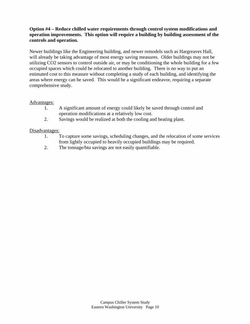
Option #4 – Reduce chilled water requirements through control system modifications and operation improvements. This option will require a building by building assessment of the controls and operation. Newer buildings like the Engineering building, and newer remodels such as Hargreaves Hall, will already be taking advantage of most energy saving measures. Older buildings may not be utilizing CO2 sensors to control outside air, or may be conditioning the whole building for a few occupied spaces which could be relocated to another building. There is no way to put an estimated cost to this measure without completing a study of each building, and identifying the areas where energy can be saved. This would be a significant endeavor, requiring a separate comprehensive study. Advantages:
1. A significant amount of energy could likely be saved through control and operation modifications at a relatively low cost.
2. Savings would be realized at both the cooling and heating plant. Disadvantages:
1. To capture some savings, scheduling changes, and the relocation of some services from lightly occupied to heavily occupied buildings may be required.
2. The tonnage/btu savings are not easily quantifiable.

Campus Chiller System Study
Eastern Washington University Page 11
PROJECT PHASING This project does not require completion in one construction phase. I have broken down the potential phases of this project below which can stand alone. Dedicating one 500 ton chiller to the Recreation Center can be a project in itself, and is not dependent on the addition of a chiller to the campus chilled water system, it also appears to be a more immediate need. Construction of the building to house a new chiller could be a project, but its cost is a relatively small component of purchasing and installing the chiller, so it was not broken out separately. Cost estimates are broken down in the same phases. Phase I: New 6” supply and 6” return water lines will be run from one of the 500 ton chillers to the tunnel, and in the tunnel to the existing chilled water supply and return branches serving the recreation Center. The new lines will tie-in downstream of the existing building isolation valves, and will allow the 500 ton chiller to serve the main chilled water loop, or just Recreation Center, when it is the only building needing chilled water, depending on which valves are open and closed. Phase II: An addition will be constructed adjacent to the existing chiller plant, and the new chiller, tower, and pumps will be installed. Piping, electrical, and control work will be completed to bring the new chiller on-line with the existing chillers.


APPENDIX “C”
Chilled Water Study Load Table September 27, 2008
Page 1 of 3
Item
EWU Facility
Cooling Coil Characteristics
AHU/ Location
AHU/
Location
AHU/
Location
AHU/
Location
AHU/
Location
AHU/
Location
AHU/
Location
AHU MBH Total/Sens.
AHU
#
Flow Rate
(gpm)
Entering Air Temperature, EATDB/EATWB
(oF)
Leaving Air Temperature. LATDB/LATWB
(oF)
Entering Water Temp. EWT (oF)
Leaving Water Temp. LWT (oF)
1 Aquatics (AQT) DHU-1/Rm.#210 563 / -- 1 70 -- / -- -- / -- 40 56.1 2 Archives (ARC) AHU-3/Rm.
#207 1194 / 1194 1 171 85.4 / 64 53.5 / 51.9 45 59
3 Art Building (ART) AHU-1, Rm. #204
AHU-3, Rm. # Duct Coils (4)
1553 / -- 660 / --
1 2
201 88
100 / 69.2 -- / --
52.7 / 51.7 -- / --
45 45
60 60
4 Cheney Hall (CHN) AHU-1, Rm. #204
AHU-2, Outside Mech. Rm. #124
720 / -- 384 / 341
1 2
180 81
--/-- 80.3 / --
-- / -- 54.5 / --
45 45
-- 54.5
5 Child Care Center (ECC) AHU-1, Rm. #? 312.8 / 312.8 1 31 86 / 62 55 / 50.5 45 -- 6 Communications Center
(CMC) AHU-1, Rm. #131
532 / -- 1 67 80 / 59.7 53 / 48.7 44 60
7 Computer & Engr. Building (CEB)
AHU-1, Rm. #003
AHU-2, Rm. #025
AHU-3, Rm. #003
AHU-4, Rm. #003
AHU-5, Rm. #025
1835 / 1835 2315 / 2315 590 / 590 435 / 435
1095 / 1095
1 2 3 4 5
245 310 80 60
150
62 / -- 62 / -- 62 / -- 67 / -- 67 / --
50 / 48 50 / 48 53 / 52 53 / 52 53 / 52
45 45 45 45 45
60 60 60 60 60
8 Huston Hall (HUS) AHU-1 (SF-1), Rm. #001
AHU-2 (SF-3), Rm. #001
AHU-6 Elec. Rm.
477 / -- 619 / -- 115 / --
1 2 3
103 87 46
80 / 66 -- / -- -- / --
58.3 / 57.6 -- / -- -- / --
50 50 50
60 -- --
9 *
Hargreaves Hall (HAR)
AHU-1 Mechanical room in the
Basement
AHU-2,3,4,5 Mechanical Room In the
Attic
1040 / 930 88 / 77 88 / 77 88 / 77 88 / 77
1 2 3 4 5
200 19 19 19 19
80 / 64 80 / 64 80 / 64 80 / 64 80 / 64
-- / -- -- / -- -- / -- -- / -- -- / --
45 45 45 45 45
55 55 55 55 55
10 Isle Hall (Fan Coil Units) (ISL) · 1st Floor – 35(9) units · 2nd Floor – 16(1) unit
AHU-1, Rooftop, (2 coils)
AHU-2, Rooftop
Fancoils 1-10 633 / 615 174 / 170 347 / --
1 2 3
99 28 53
80.6 / 62.3 79.3 / 61.9
80 / 63
51.8 / 50.7 53.4 / 51.6
54 / 52
44 44 44
56.8 56.6 54
11 Jim Thorpe Fieldhouse (JTF)
AHU-1, Mezzanine Mech. Rm.
128 / 104 1 15 84 / 64.2 59 / 55.6 44 60
12 JFK Library (JFK) AHU-1, Outdoor Mech. Rm.?
AHU-2, SE Penthouse Mech. Rm. P02
AHU-3, SE Penthouse Mech. Rm. P02
AHU-4 , Rm. #L04
AHU-5, Rm. #L04
AHU-6 , NW Penthouse Mech. Rm. #P01
AHU-7, NW Penthouse Mech. Rm. #P01 plus AHU-10, Rm. #U12F
686 / -- 554 / -- 944 / -- 602 / -- 568 / -- 638 / -- 614 / -- 151 / --
1 2 3 4 5 6 7
10
130 110 220 145 125 140 135 35
85 / -- 85 / -- 85 / -- 85 / -- 85 / -- 85 / -- 85 / -- 89 / --
54.5 / -- 55 / -- 55 / --
54.6 / -- 54.7 / -- 54.7 / -- 55 / -- 57 / --
48 48 48 48 48 48 48 48
58.6 58 57
56.3 57.1 57.1 57.1 57
13 Kingston Hall (KGS) AHU-1, Rm. # M-2
1660 / 1300
1 250 80 / 67 53 / 52 45 60

Chilled Water Study Load Table (Continued) September 27, 2008
Page 2 of 3
Item
EWU Facility
Chilled Water Cooling Coils Cooling Coil Characteristics
AHU/ Location
AHU/
Location
AHU/
Location
AHU/
Location
AHU/
Location
AHU/
Location
AHU/
Location
AHU MBH Total/Sens.
AHU
#
Flow Rate
(gpm)
Entering Air Temperature, EATDB/EATWB
(oF)
Leaving Air Temperature. LATDB/LATWB
(oF)
Entering Water Temp. EWT (oF)
Leaving Water Temp. LWT (oF)
14 Martin Hall (MAR) AHU-1, Rm. #150
AHU-3, Rm. #255
AHU-4, Pent House Mech. Rm. #?
251 / -- 1
70 84 / 53 -- / -- 45 55
15 Monroe Hall (MON) AHU-1, Rm. #100.
AHU-2, Rm. #100
AHU-3, Rm. #100
443 / 390 424 / 403 503 / 415
1 2 3
68 52 78
81 / 62 81 / 63
83 / 63.5
50 / 49 52 / 51 50 / 49
45 45 45
58.5 61.5 57.9
16 Music Building (MUS) AHU-1&2, Rm. #122
730 / -- 1 85 80 / 59.7 55 / 49.5 44 60
17 Patterson Hall I (PAT I) AHU-1, Rm. #164
1944 / -- 1 360 80 / 61.5 50 / 48 44 --
18 Patterson Hall II (PAT II) AHU-1, Rm. #108
2010 / -- 1 360 80 / 61.5 50 / 48 44 --
19 P.E. Activities (PEA) AHU-4, Rm. #108. Coaches Offices
AHU-11, Rm. #115
AHU-13, Rm. #128 (double doors) Laundry
46 / -- 418 / 376 361 / 348
1 2 3
9 61
52.7
81 / -- 82.3 / 62.2 82.3 / 62.2
-- / -- 50 / 48.5
50.2 / 49.4
45 44 44
-- / -- 57.7 57.7
20 P.E. Classroom (PEC) (Fan Coil Units)
AHU-1, Rm. #001
AHU-2, Rm. #103 Fancoils
254 / 223 529 / --
1 2
84 175
82.5 / 64.3 --/--
55 / 53 -- / --
44 44
60 60
21 Pavilion (PAV) AHU-1, Rm. #203
AHU-2, Rm. #216
AHU-3, Rm. #236
AHU-4, Rm. #500
AHU-5, N. Penthouse Rm. #504
FC-A (1) and FC-B (8)
333 / -- 337 / -- 87 / --
1951 / -- 1951 / --
1 2 3 4 5
42 42 11
244 244
-- / -- -- / -- -- / -- -- / -- -- / --
-- / -- -- / -- -- / -- -- / -- -- / --
44 44 44 44 44
60 60 60 60 60
22 Pence Union Building (PUB)
AHU-1, Old Mech. Rm. #120
AHU-2, Old Mech. Rm. #120
AHU-3, Old Mech. Rm. #120
AHU-4, Old Mech. Rm. #120
AHU-5, Penthouse Mech. Rm. ?
AHU-6, Penthouse Mech. Rm. ?
946 / 820 972 / 870 950 / 840 455 / -- 522 / -- 367 / --
1 2 3 4 5 6
118 122 119 57
150 74
84.2 / 63.5 86.8 / 64.1 89.5 / 64.8
95 / 65 86 / -- 86 / --
50 / 48.5 50 / 48.5 50 / 48.5 50 / 47.5
53 / -- 53 / --
44 44 44 44 46 46
60 60 60 60 60 60
23 Radio/TV Building (RTV) AHU-1, Outside Mech. Rm. #200
1211 / 955
1 165 82.4 / 63.8 50.1 / 48.8 44 58.6
24 Recital Hall AHU-1, Rm. #202
300 / --
1 44 80 / 59.7 55 / 49.5 44 60
25 Rozell Heating Plant (ROZ) AHU-1, Rooftop Unit.
AHU-1, Basement, UPS Area
AHU-2, Basement, UPS Area
193 / -- 57 / 57 57 / 57
1 2 3
45 15 15
84.5 / 63 77.7 / 62 77.8 / 62
53 / 51.6 54 / 53 54 / 53
45 44 44
63.6 52.6 52.6
26 Science Building (SCI) AHU-1, Rm. # 301.
AHU-2, Rm. # 301.
AHU-3, W. or N. Mech. Rm. #004
AHU-4, E. or S Mech. Rm. #001
2279 / -- 186 / --
3698 / 3666 3048 / 3021
1 2 3 4
380 31
760 620
93 / 76 93 / 67 93 / 64 93 / 64
55 / 52 55 / 52
55 / 49.5 55 / 49.5
45 45 48 48
57 57 58 58
27 Senior Hall (SNR) AHU #1, Mech. Rm. # 001
AHU #2, Mech. Rm. # 001
FC 3-6 750 / 750 750 / 750 641 / --
1 2 3
100 100
9
83 / 64 83 / 64 82 / --
51.1 / 51.1 51.1 / 51.1
56 / --
45 45 45
60 60 60
28 Showalter Hall (SHW) AHU-1, New AHU-2, New 1300 / -- 309 / --
1 2
248 62
81.7 / 61.7 -- / --
52.7 / 49.8 -- / --
45 45
55 --
29 Sutton Hall (SUT) AHU-1, Mech. Rm. # 001
486 / -- 1 100 84 / 63.7 51.8 / 50.8 46 55.7

Chilled Water Study Load Table (Continued) September 27, 2008
Page 3 of 3
Item
EWU Facility
Chilled Water Cooling Coils Cooling Coil Characteristics
AHU/ Location
AHU/
Location
AHU/
Location
AHU/
Location
AHU/
Location
AHU/
Location
AHU/
Location
AHU MBH Total/Sens.
AHU
#
Flow Rate
(gpm)
Entering Air Temperature, EATDB/EATWB
(oF)
Leaving Air Temperature. LATDB/LATWB
(oF)
Entering Water Temp. EWT (oF)
Leaving Water Temp. LWT (oF)
30 Tawanka (TAW) AHU-1, Penthouse Mech. Rm. #302
AHU-2, Penthouse Mech. Rm. #302
AHU-3, Penthouse Mech. Rm. #302.
966 / -- 1005 / -- 1073 / --
1 2 3
193 175 179
81 / -- 79 / -- 92 / --
45 45 45
55 56.5 57
31 Theatre (Drama) (THE) AHU-1, Outside Mech. Rm. #113
AHU-2, Mezz. Mech. Rm. #133A
620 / 584 493 / 474
1 2
77 77
83 / 63.8 84.6 / 64
44 44
60.4 57.5
32 *
University Recreation Center (URC)
AHU-1, Rooftop Unit
AHU-2, Rooftop Unit
AHU-3, Rooftop Unit
AHU-4, Rooftop Unit
AHU-5, Rooftop Unit
AHU-6, Rooftop Unit
2446 / 2152 493 / 484 125 / 122 576 / 567 865 / 696 280 / 269
1 2 3 4 5 6
335 124 24.9 96.2 123 35
78 / 61 87 / 65 83 / 63 75 / 65 81 / 65 93 / 64
47.6 / 47.2 53.5 / 51.8 48.2 / 47.8 53.1 / 52.5 53.8 / 52.7 67.5 / 55.1
42 44 42 42 42 42
56.2 56.6 57.1 56
57.9 56.2
33 WSP Crime Lab. (WSP) AHU-1, Penthouse Mech. Rm. #201
AHU-2 Penthouse Mech. Rm. #201
1147 / 1131 1147 / 1131
1 2
153 153
96 / 67 96 / 67
45 60
34 Williamson Hall (WLM) AHU-1, Penthouse Mech. Rm. #?
1710 / -- 1 350 84 / 48 45 55
TOTALS 67,486 11,198 * The cooling load for this building was not served in 2007, and is not included in the 2007 Maximum Design Load. ** The loop flow rate may not match the sum of the coil flow rates, since they are fed by secondary pumps. 2007 MAXIMUM DESIGN LOAD 61,309 MBH 10,184 GPM ** 2008 MAXIMUM DESIGN LOAD 67,486 MBH 11,198 GPM **
Campus Chiller System Study
Eastern Washington University Page 17
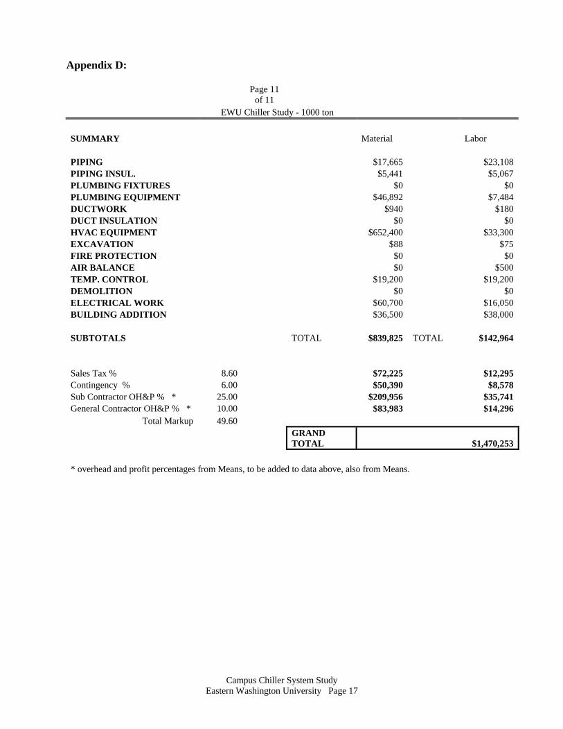
Appendix D:
Page 11
of 11 EWU Chiller Study - 1000 ton SUMMARY Material Labor PIPING $17,665 $23,108 PIPING INSUL. $5,441 $5,067 PLUMBING FIXTURES $0 $0 PLUMBING EQUIPMENT $46,892 $7,484 DUCTWORK $940 $180 DUCT INSULATION $0 $0 HVAC EQUIPMENT $652,400 $33,300 EXCAVATION $88 $75 FIRE PROTECTION $0 $0 AIR BALANCE $0 $500 TEMP. CONTROL $19,200 $19,200 DEMOLITION $0 $0 ELECTRICAL WORK $60,700 $16,050 BUILDING ADDITION $36,500 $38,000 SUBTOTALS TOTAL $839,825 TOTAL $142,964 Sales Tax % 8.60 $72,225 $12,295 Contingency % 6.00 $50,390 $8,578 Sub Contractor OH&P % * 25.00 $209,956 $35,741 General Contractor OH&P % * 10.00 $83,983 $14,296
Total Markup 49.60
GRAND TOTAL $1,470,253
* overhead and profit percentages from Means, to be added to data above, also from Means.

Campus Chiller System Study
Eastern Washington University Page 18
Appendix E:
Page 11
of 11 EWU Chiller Study - 2000 ton SUMMARY Material Labor PIPING $86,090 $108,864 PIPING INSUL. $27,192 $22,982 PLUMBING FIXTURES $0 $0 PLUMBING EQUIPMENT $83,743 $13,339 DUCTWORK $940 $180 DUCT INSULATION $0 $0 HVAC EQUIPMENT $1,152,400 $55,100 EXCAVATION $88 $75 FIRE PROTECTION $0 $0 AIR BALANCE $0 $700 TEMP. CONTROL $21,000 $18,000 DEMOLITION $0 $0 ELECTRICAL WORK $121,400 $32,100 BUILDING ADDITION $35,500 $39,000 SUBTOTALS TOTAL $1,528,352 TOTAL $290,341 Sales Tax % 8.60 $131,438 $24,969 Contingency % 6.00 $91,701 $17,420 Sub Contractor OH&P % * 25.00 $382,088 $72,585 General Contractor OH&P % * 10.00 $152,835 $29,034
Total Markup 49.60
GRAND TOTAL $2,720,765
* overhead and profit percentages from Means, to be added to data above, also from Means.