Camlock Fittings Technical Information - · PDF fileThe standard for cam action couplings has...
12
Camlock Fittings Technical Information Proven economy in reliable transfer of corrosive and hard to handle fluids
Transcript of Camlock Fittings Technical Information - · PDF fileThe standard for cam action couplings has...
Camlock Fittings Technical Information
Proven economy in reliable transfer of corrosive and hard to handle fluids
Clark Beesley
PFD logo n address correct ver
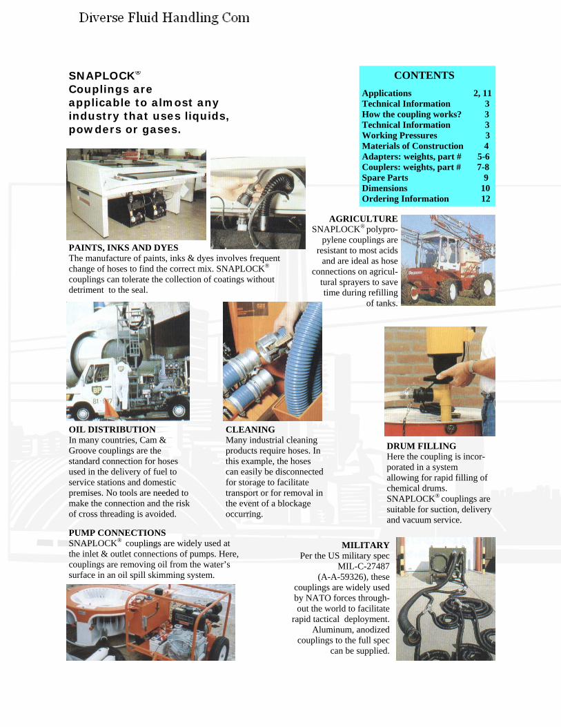
DRUM FILLING Here the coupling is incor-porated in a system allowing for rapid filling of chemical drums. SNAPLOCK® couplings are suitable for suction, delivery and vacuum service.
MILITARY Per the US military spec
MIL-C-27487 (A-A-59326), these
couplings are widely used by NATO forces through-out the world to facilitate
rapid tactical deployment. Aluminum, anodized
couplings to the full spec can be supplied.
CLEANING Many industrial cleaning products require hoses. In this example, the hoses can easily be disconnected for storage to facilitate transport or for removal in the event of a blockage occurring.
SNAPLOCK® Couplings are applicable to almost any industry that uses liquids, powders or gases.
PAINTS, INKS AND DYES The manufacture of paints, inks & dyes involves frequent change of hoses to find the correct mix. SNAPLOCK®
couplings can tolerate the collection of coatings without detriment to the seal.
OIL DISTRIBUTION In many countries, Cam & Groove couplings are the standard connection for hoses used in the delivery of fuel to service stations and domestic premises. No tools are needed to make the connection and the risk of cross threading is avoided.
AGRICULTURE SNAPLOCK® polypro-
pylene couplings are resistant to most acids
and are ideal as hose connections on agricul-
tural sprayers to save time during refilling
of tanks.
PUMP CONNECTIONS SNAPLOCK® couplings are widely used at the inlet & outlet connections of pumps. Here, couplings are removing oil from the water’s surface in an oil spill skimming system.
CONTENTS Applications 2, 11 Technical Information 3 How the coupling works? 3 Technical Information 3 Working Pressures 3 Materials of Construction 4 Adapters: weights, part # 5-6 Couplers: weights, part # 7-8 Spare Parts 9 Dimensions 10 Ordering Information 12
Clark Beesley
New Stamp
3
SNAPLOCK® COUPLINGS Technical Information
SPECIFICATIONS
The standard for cam action couplings has traditionally been based on the US Military Specification, MIL-C-27487, which laid down the casting method, materials, dimensions, tolerances, pressure ratings and inspection procedures. MIL-C-27487 guaranteed interchangeability of products. MIL-C-27487 has now been declared obsolete, and replaced by a new US Federal standard A-A-59326. It is easy to reduce the cost of couplings by not machining adaptors, reducing wall thickness or by using casting methods not approved by the specification. However, the potential additional cost of this is possible leakage, reduced life and costly down time. Our metallic couplings are manufactured fully in accordance with the dimensions and tolerances of MIL-C-27487/A-A-59326 and pressure-tested to three times the recommended working pressure, with polypropylene being pressure tested to twice its working pressure to allow for surges in the line and give enhanced safety. All couplings are supplied with locking feature as standard. Safety clips may be inserted to lock handles to prevent disconnection during product transfer.
All descriptive matter, illustrations, dimensions and weights issued in this brochure are for guidance only and cannot be held as binding in any way. We reserve the right to change specifications and other information included in this brochure without any prior notice. We recommend that you contact us to be sure that the information you have is current. All information given in this brochure has been carefully compiled and thoroughly checked. However, no responsibility for possible errors or omissions can be assumed.
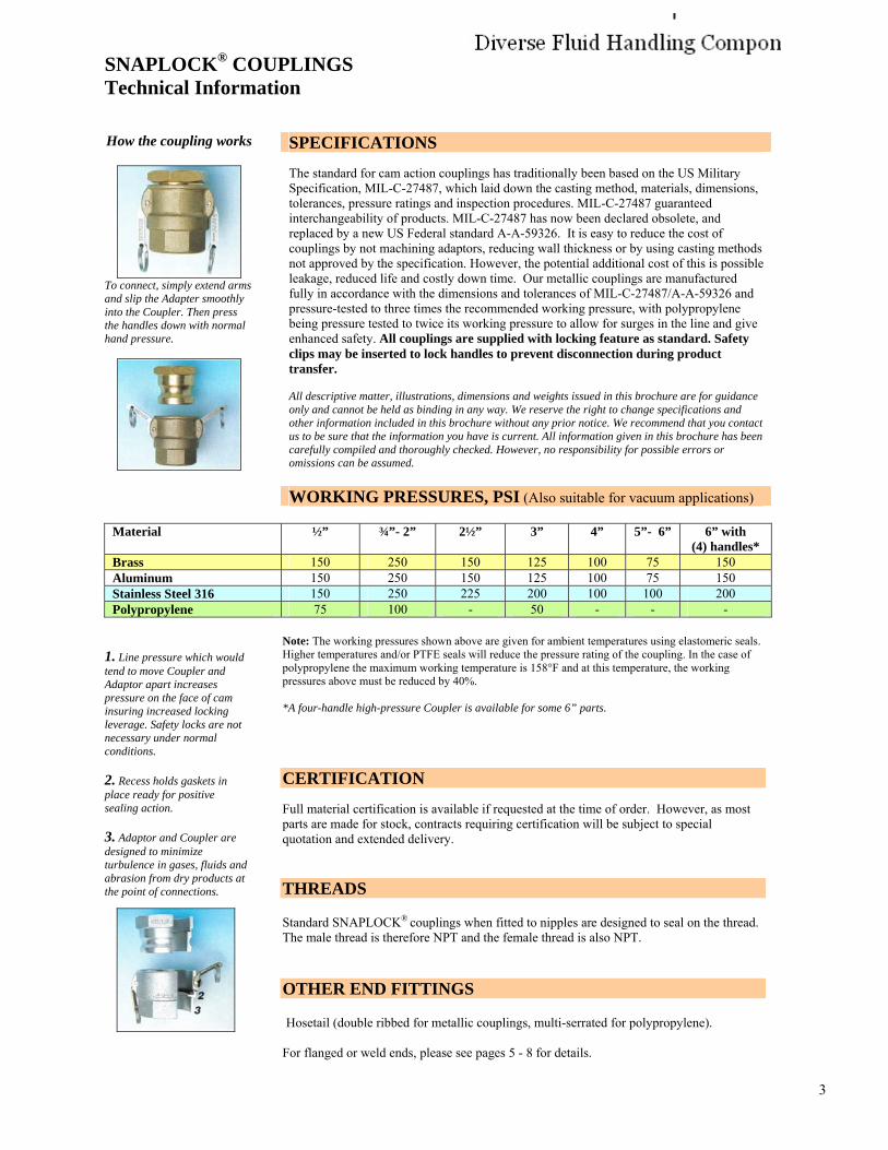
How the coupling works
To connect, simply extend arms and slip the Adapter smoothly into the Coupler. Then press the handles down with normal hand pressure.
WORKING PRESSURES, PSI (Also suitable for vacuum applications)
Material ½” ¾”- 2” 2½” 3” 4” 5”- 6” 6” with (4) handles*
Brass 150 250 150 125 100 75 150 Aluminum 150 250 150 125 100 75 150Stainless Steel 316 150 250 225 200 100 100 200 Polypropylene 75 100 - 50 - - -
1. Line pressure which would tend to move Coupler and Adaptor apart increases pressure on the face of cam insuring increased locking leverage. Safety locks are not necessary under normal conditions.
2. Recess holds gaskets in place ready for positive sealing action.
3. Adaptor and Coupler are designed to minimize turbulence in gases, fluids and abrasion from dry products at the point of connections.
Note: The working pressures shown above are given for ambient temperatures using elastomeric seals. Higher temperatures and/or PTFE seals will reduce the pressure rating of the coupling. In the case of polypropylene the maximum working temperature is 158°F and at this temperature, the working pressures above must be reduced by 40%.
*A four-handle high-pressure Coupler is available for some 6” parts.
CERTIFICATION
Full material certification is available if requested at the time of order. However, as most parts are made for stock, contracts requiring certification will be subject to special quotation and extended delivery.
THREADS
Standard SNAPLOCK® couplings when fitted to nipples are designed to seal on the thread. The male thread is therefore NPT and the female thread is also NPT.
OTHER END FITTINGS
Hosetail (double ribbed for metallic couplings, multi-serrated for polypropylene).
For flanged or weld ends, please see pages 5 - 8 for details.
Clark Beesley
New Stamp
4
SNAPLOCK® COUPLINGS Technical Information
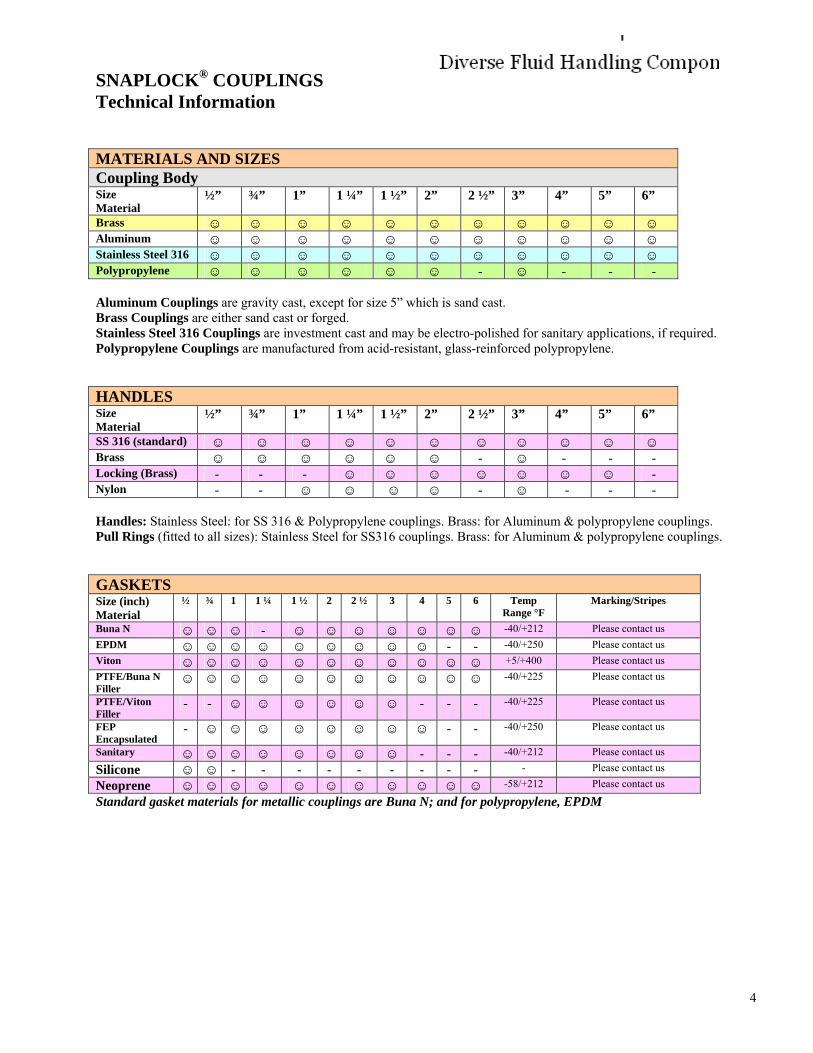
MATERIALS AND SIZES Coupling Body Size Material
½” ¾” 1” 1 ¼” 1 ½” 2” 2 ½” 3” 4” 5” 6”
Brass ☺ ☺ ☺ ☺ ☺ ☺ ☺ ☺ ☺ ☺ ☺ Aluminum ☺ ☺ ☺ ☺ ☺ ☺ ☺ ☺ ☺ ☺ ☺ Stainless Steel 316 ☺ ☺ ☺ ☺ ☺ ☺ ☺ ☺ ☺ ☺ ☺ Polypropylene ☺ ☺ ☺ ☺ ☺ ☺ - ☺ - - -
Aluminum Couplings are gravity cast, except for size 5” which is sand cast. Brass Couplings are either sand cast or forged. Stainless Steel 316 Couplings are investment cast and may be electro-polished for sanitary applications, if required. Polypropylene Couplings are manufactured from acid-resistant, glass-reinforced polypropylene.
HANDLES Size Material
½” ¾” 1” 1 ¼” 1 ½” 2” 2 ½” 3” 4” 5” 6”
SS 316 (standard) ☺ ☺ ☺ ☺ ☺ ☺ ☺ ☺ ☺ ☺ ☺ Brass ☺ ☺ ☺ ☺ ☺ ☺ - ☺ - - - Locking (Brass) - - - ☺ ☺ ☺ ☺ ☺ ☺ ☺ - Nylon - - ☺ ☺ ☺ ☺ - ☺ - - -
Handles: Stainless Steel: for SS 316 & Polypropylene couplings. Brass: for Aluminum & polypropylene couplings. Pull Rings (fitted to all sizes): Stainless Steel for SS316 couplings. Brass: for Aluminum & polypropylene couplings.
GASKETS Size (inch) Material
½ ¾ 1 1 ¼ 1 ½ 2 2 ½ 3 4 5 6 Temp Range °F
Marking/Stripes
Buna N ☺ ☺ ☺ - ☺ ☺ ☺ ☺ ☺ ☺ ☺ -40/+212 Please contact us EPDM ☺ ☺ ☺ ☺ ☺ ☺ ☺ ☺ ☺ - - -40/+250 Please contact usViton ☺ ☺ ☺ ☺ ☺ ☺ ☺ ☺ ☺ ☺ ☺ +5/+400 Please contact usPTFE/Buna N Filler
☺ ☺ ☺ ☺ ☺ ☺ ☺ ☺ ☺ ☺ ☺ -40/+225 Please contact us
PTFE/Viton Filler
- - ☺ ☺ ☺ ☺ ☺ ☺ - - - -40/+225 Please contact us
FEP Encapsulated
- ☺ ☺ ☺ ☺ ☺ ☺ ☺ ☺ - - -40/+250 Please contact us
Sanitary ☺ ☺ ☺ ☺ ☺ ☺ ☺ ☺ - - - -40/+212 Please contact us
Silicone ☺ ☺ - - - - - - - - - - Please contact us
Neoprene ☺ ☺ ☺ ☺ ☺ ☺ ☺ ☺ ☺ ☺ ☺ -58/+212 Please contact us
Standard gasket materials for metallic couplings are Buna N; and for polypropylene, EPDM
Clark Beesley
New Stamp
5
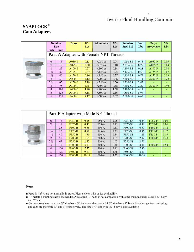
SNAPLOCK® Cam Adapters
Nominal Size
inch mm
Brass Wt. Lbs
Aluminum Wt. Lbs
Stainless Steel 316
Wt. Lbs
Poly- propylene
Wt. Lbs
Part A Adapter with Female NPT Threads ½ 13 A050-B 0.13 A050-A 0.04 A050-SS 0.13 A050-P 0.05 ¾ 19 A075-B 0.30 A075-A 0.10 A075-SS 0.29 A075-P 0.04 1 25 A100-B 0.27 A100-A 0.14 A100-SS 0.28 A100-P 0.08
1¼ 32 A125-B 0.57 A125-A 0.25 A125-SS 0.58 A125-P 0.07 1½ 40 A150-B 0.86 A150-A 0.27 A150-SS 0.79 A150-P 0.13 2 50 A200-B 1.12 A200-A 0.36 A200-SS 1.11 A200-P 0.22
2 ½ 65 A250-B 2.19 A250-A 0.50 A250-SS 2.43 - - 3 75 A300-B 2.45 A300-A 0.68 A300-SS 2.22 A300-P 0.40 4 100 A400-B 4.40 A400-A 1.38 A400-SS 4.14 - - 5 125 A500-B 6.18 A500-A 2.16 A500-SS 5.94 - - 6 150 A600-B 9.17 A600-A 2.37 A600-SS 6.62 - -
Part F Adapter with Male NPT threads ½ 13 F050-B 0.25 050-A 0.08 F050-SS 0.24 F050-P 0.06 ¾ 19 F075-B 0.45 075-A 0.13 F075-SS 0.39 F075-P 0.06 1 25 F100-B 0.55 100-A 0.18 F100-SS 0.57 F100-P 0.12
1¼ 32 F125-B 0.98 125-A 0.33 F125-SS 0.96 F125-P 0.12 1½ 40 F150-B 1.30 150-A 0.34 F150-SS 1.29 F150-P 0.19 2 50 F200-B 1.69 200-A 0.69 F200-SS 2.02 F200-P 0.23
2 ½ 65 F250-B 2.72 250-A 1.02 F250-SS 2.75 - - 3 75 F300-B 3.13 300-A 1.30 F300-SS 4.31 F300-P 0.54 4 100 F400-B 7.77 400-A 2.11 F400-SS 7.33 - - 5 125 F500-B 9.13 500-A 2.86 F500-SS 8.89 - - 6 150 F600-B 10.19 600-A 3.22 F600-SS 10.38 - -
Notes:
■ Parts in italics are not normally in stock. Please check with us for availability.■ ½” metallic couplings have one handle. Also a true ½” body is not compatible with other manufacturers using a ¾” body
and ½” end.■ On polypropylene parts, the ½” size has a ¾” body and the standard 1 ¼” size has a 1” body. Handles, gaskets, dust plugs
and caps are therefore ¾” and 1” respectively. The size 1¼” size with 1½” body is also available.
Clark Beesley
New Stamp
6
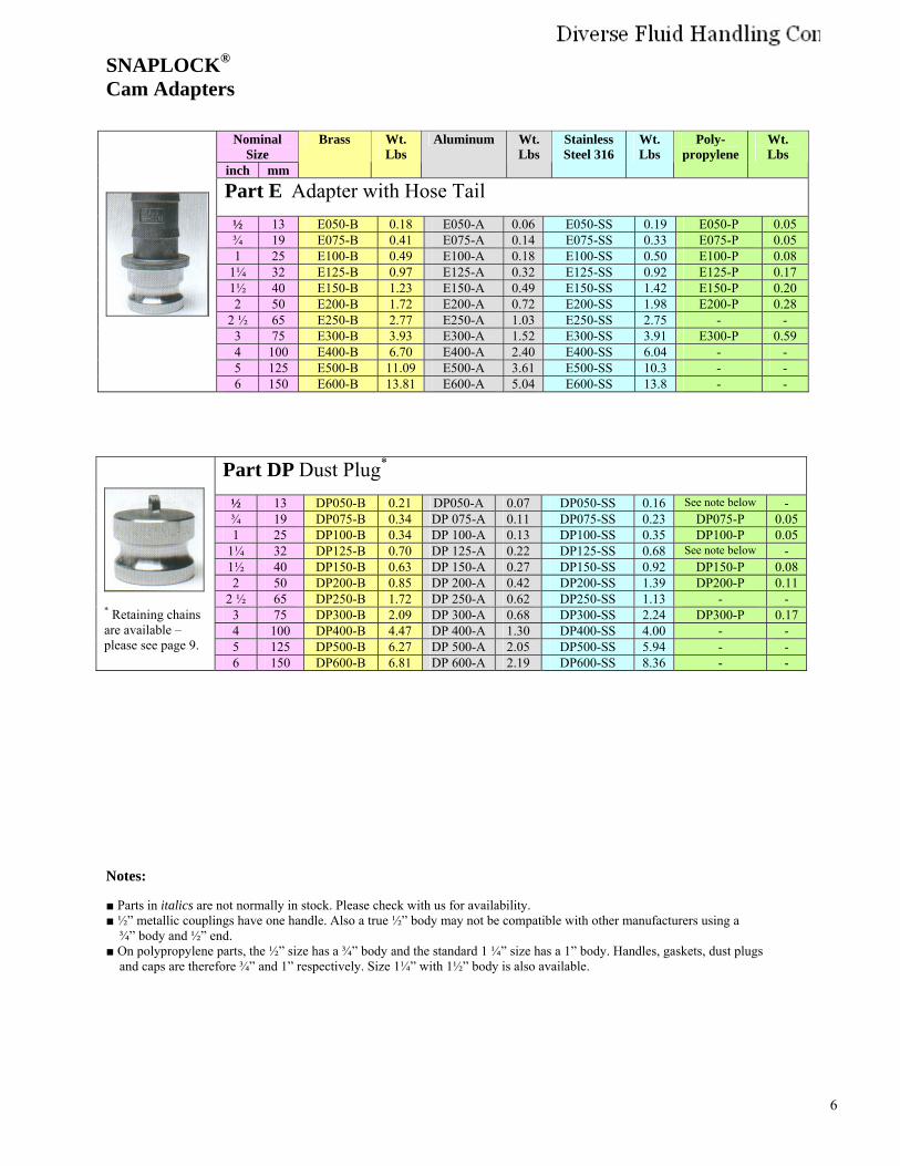
SNAPLOCK®
Cam Adapters
Nominal Size
inch mm
Brass Wt. Lbs
Aluminum Wt. Lbs
Stainless Steel 316
Wt. Lbs
Poly- propylene
Wt. Lbs
Part E Adapter with Hose Tail ½ 13 E050-B 0.18 E050-A 0.06 E050-SS 0.19 E050-P 0.05 ¾ 19 E075-B 0.41 E075-A 0.14 E075-SS 0.33 E075-P 0.05 1 25 E100-B 0.49 E100-A 0.18 E100-SS 0.50 E100-P 0.08
1¼ 32 E125-B 0.97 E125-A 0.32 E125-SS 0.92 E125-P 0.17 1½ 40 E150-B 1.23 E150-A 0.49 E150-SS 1.42 E150-P 0.20 2 50 E200-B 1.72 E200-A 0.72 E200-SS 1.98 E200-P 0.28
2 ½ 65 E250-B 2.77 E250-A 1.03 E250-SS 2.75 - - 3 75 E300-B 3.93 E300-A 1.52 E300-SS 3.91 E300-P 0.59 4 100 E400-B 6.70 E400-A 2.40 E400-SS 6.04 - - 5 125 E500-B 11.09 E500-A 3.61 E500-SS 10.3 - - 6 150 E600-B 13.81 E600-A 5.04 E600-SS 13.8 - -
Notes:
■ Parts in italics are not normally in stock. Please check with us for availability.■ ½” metallic couplings have one handle. Also a true ½” body may not be compatible with other manufacturers using a
¾” body and ½” end.■ On polypropylene parts, the ½” size has a ¾” body and the standard 1 ¼” size has a 1” body. Handles, gaskets, dust plugs
and caps are therefore ¾” and 1” respectively. Size 1¼” with 1½” body is also available.
Part DP Dust Plug*
½ 13 DP050-B 0.21 DP050-A 0.07 DP050-SS 0.16 See note below - ¾ 19 DP075-B 0.34 DP 075-A 0.11 DP075-SS 0.23 DP075-P 0.05 1 25 DP100-B 0.34 DP 100-A 0.13 DP100-SS 0.35 DP100-P 0.05
1¼ 32 DP125-B 0.70 DP 125-A 0.22 DP125-SS 0.68 See note below - 1½ 40 DP150-B 0.63 DP 150-A 0.27 DP150-SS 0.92 DP150-P 0.08 2 50 DP200-B 0.85 DP 200-A 0.42 DP200-SS 1.39 DP200-P 0.11
2 ½ 65 DP250-B 1.72 DP 250-A 0.62 DP250-SS 1.13 - - 3 75 DP300-B 2.09 DP 300-A 0.68 DP300-SS 2.24 DP300-P 0.17 4 100 DP400-B 4.47 DP 400-A 1.30 DP400-SS 4.00 - - 5 125 DP500-B 6.27 DP 500-A 2.05 DP500-SS 5.94 - -
* Retaining chainsare available – please see page 9.
6 150 DP600-B 6.81 DP 600-A 2.19 DP600-SS 8.36 - -
Clark Beesley
New Stamp
7
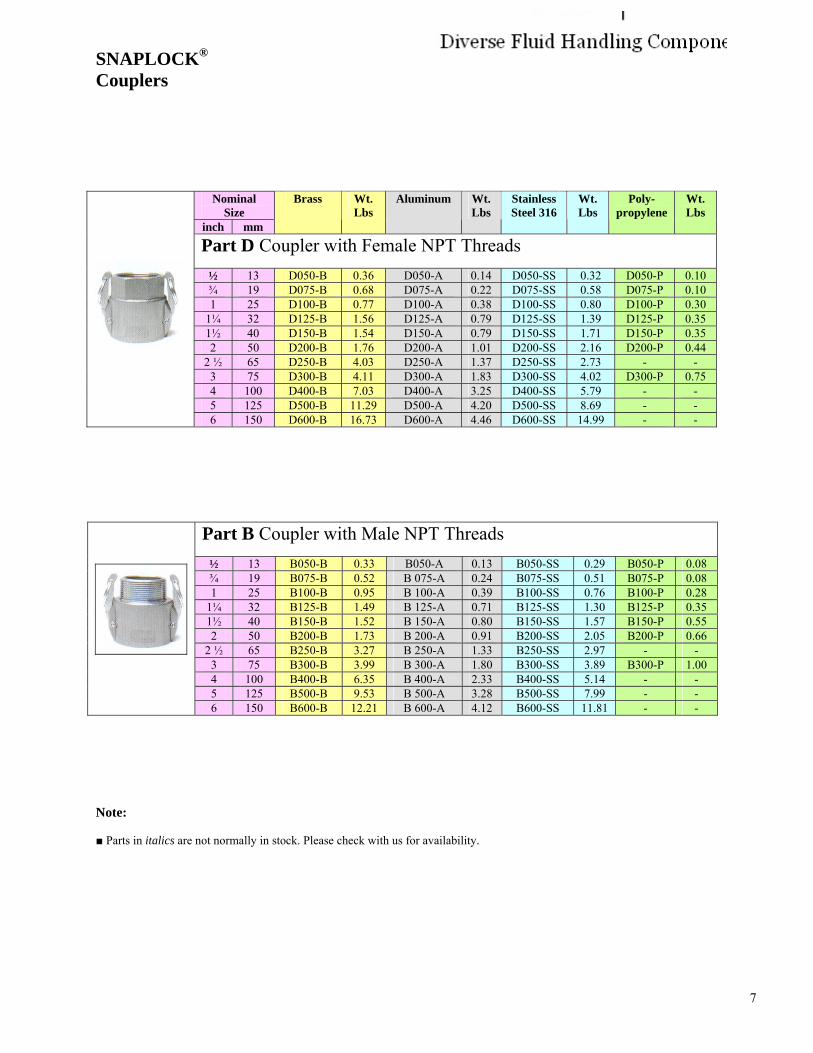
SNAPLOCK®
Couplers
Nominal Size
inch mm
Brass Wt. Lbs
Aluminum Wt. Lbs
Stainless Steel 316
Wt. Lbs
Poly- propylene
Wt. Lbs
Part D Coupler with Female NPT Threads ½ 13 D050-B 0.36 D050-A 0.14 D050-SS 0.32 D050-P 0.10 ¾ 19 D075-B 0.68 D075-A 0.22 D075-SS 0.58 D075-P 0.10 1 25 D100-B 0.77 D100-A 0.38 D100-SS 0.80 D100-P 0.30
1¼ 32 D125-B 1.56 D125-A 0.79 D125-SS 1.39 D125-P 0.35 1½ 40 D150-B 1.54 D150-A 0.79 D150-SS 1.71 D150-P 0.35 2 50 D200-B 1.76 D200-A 1.01 D200-SS 2.16 D200-P 0.44
2 ½ 65 D250-B 4.03 D250-A 1.37 D250-SS 2.73 - - 3 75 D300-B 4.11 D300-A 1.83 D300-SS 4.02 D300-P 0.75 4 100 D400-B 7.03 D400-A 3.25 D400-SS 5.79 - - 5 125 D500-B 11.29 D500-A 4.20 D500-SS 8.69 - - 6 150 D600-B 16.73 D600-A 4.46 D600-SS 14.99 - -
Part B Coupler with Male NPT Threads ½ 13 B050-B 0.33 B050-A 0.13 B050-SS 0.29 B050-P 0.08 ¾ 19 B075-B 0.52 B 075-A 0.24 B075-SS 0.51 B075-P 0.08 1 25 B100-B 0.95 B 100-A 0.39 B100-SS 0.76 B100-P 0.28
1¼ 32 B125-B 1.49 B 125-A 0.71 B125-SS 1.30 B125-P 0.35 1½ 40 B150-B 1.52 B 150-A 0.80 B150-SS 1.57 B150-P 0.55 2 50 B200-B 1.73 B 200-A 0.91 B200-SS 2.05 B200-P 0.66
2 ½ 65 B250-B 3.27 B 250-A 1.33 B250-SS 2.97 - - 3 75 B300-B 3.99 B 300-A 1.80 B300-SS 3.89 B300-P 1.00 4 100 B400-B 6.35 B 400-A 2.33 B400-SS 5.14 - - 5 125 B500-B 9.53 B 500-A 3.28 B500-SS 7.99 - - 6 150 B600-B 12.21 B 600-A 4.12 B600-SS 11.81 - -
Note:
■ Parts in italics are not normally in stock. Please check with us for availability.
Clark Beesley
New Stamp
8
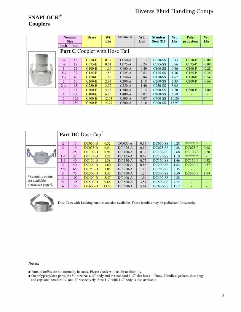
SNAPLOCK® Couplers
Nominal Size
inch mm
Brass Wt. Lbs
Aluminum Wt. Lbs
Stainless Steel 316
Wt. Lbs
Poly- propylene
Wt. Lbs
Part C Coupler with Hose Tail ½ 13 C050-B 0.37 C050-A 0.13 C050-SS 0.33 C050-P 0.08 ¾ 19 C075-B 0.61 C075-A 0.24 C075-SS 0.56 C075-P 0.08 1 25 C100-B 1.06 C100-A 0.40 C100-SS 0.86 C100-P 0.28
1¼ 32 C125-B 1.56 C125-A 0.83 C125-SS 1.36 C125-P 0.35 1½ 40 C150-B 1.88 C150-A 0.84 C150-SS 1.67 C150-P 0.54 2 50 C200-B 2.93 C200-A 1.18 C200-SS 2.33 C200-P 0.66
2 ½ 65 C250-B 3.72 C250-A 1.40 C250-SS 3.05 - - 3 75 C300-B 5.43 C300-A 2.14 C300-SS 4.70 C300-P 1.00 4 100 C400-B 6.86 C400-A 3.07 C400-SS 6.59 - - 5 125 C500-B 12.63 C500-A 4.07 C500-SS 10.20 - - 6 150 C600-B 15.99 C600-A 6.16 C600-SS 15.97 - -
Part DC Dust Cap*
½ 13 DC050-B 0.32 DC050-A 0.13 DC050-SS 0.28 See note below - ¾ 19 DC075-B 0.54 DC 075-A 0.19 DC075-SS 0.28 DC075-P 0.08 1 25 DC100-B 0.91 DC 100-A 0.37 DC100-SS 0.68 DC100-P 0.20
1¼ 32 DC125-B 1.28 DC 125-A 0.68 DC125-SS 1.19 See note below - 1½ 40 DC150-B 1.38 DC 150-A 0.75 DC150-SS 1.46 DC150-P 0.52 2 50 DC200-B 1.60 DC 200-A 0.88 DC200-SS 1.82 DC200-P 0.57
2 ½ 65 DC250-B 3.05 DC 250-A 1.17 DC250-SS 2.35 - - 3 75 DC300-B 3.43 DC 300-A 1.25 DC300-SS 3.50 DC300-P 1.04 4 100 DC400-B 5.47 DC 400-A 1.94 DC400-SS 4.88 - - 5 125 DC500-B 9.68 DC 500-A 3.54 DC500-SS 7.72 - -
*Retaining chainsare available - please see page 9. 6 150 DC600-B 13.53 DC 600-A 5.61 DC600-SS 11.2 - -
Dust Caps with Locking handles are also available. These handles may be padlocked for security.
Notes:
■ Parts in italics are not normally in stock. Please check with us for availability.■ On polypropylene parts, the ½” size has a ¾” body and the standard 1 ¼” size has a 1” body. Handles, gaskets, dust plugs
and caps are therefore ¾” and 1” respectively. Size 1¼” with 1½” body is also available.
Clark Beesley
New Stamp
9
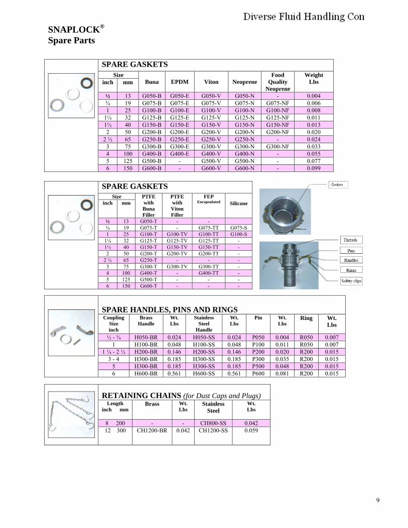
SNAPLOCK® Spare Parts
SPARE HANDLES, PINS AND RINGSCoupling
Size inch
Brass Handle
Wt. Lbs
Stainless Steel
Handle
Wt. Lbs
Pin Wt. Lbs
Ring Wt. Lbs
½ - ¾ H050-BR 0.024 H050-SS 0.024 P050 0.004 R050 0.007 1 H100-BR 0.048 H100-SS 0.048 P100 0.011 R050 0.007
1 ¼ - 2 ½ H200-BR 0.146 H200-SS 0.146 P200 0.020 R200 0.015 3 - 4 H300-BR 0.185 H300-SS 0.185 P300 0.035 R200 0.015
5 H300-BR 0.185 H300-SS 0.185 P500 0.048 R200 0.015 6 H600-BR 0.561 H600-SS 0.561 P600 0.081 R200 0.015
RETAINING CHAINS (for Dust Caps and Plugs) Length
inch mm Brass Wt.
Lbs Stainless
Steel Wt. Lbs
8 200 - - CH800-SS 0.042 12 300 CH1200-BR 0.042 CH1200-SS 0.059
SPARE GASKETSSize
inch mm Buna EPDM Viton Neoprene Food
Quality Neoprene
Weight Lbs
½ 13 G050-B G050-E G050-V G050-N - 0.004 ¾ 19 G075-B G075-E G075-V G075-N G075-NF 0.006 1 25 G100-B G100-E G100-V G100-N G100-NF 0.008
1¼ 32 G125-B G125-E G125-V G125-N G125-NF 0.011 1½ 40 G150-B G150-E G150-V G150-N G150-NF 0.013 2 50 G200-B G200-E G200-V G200-N G200-NF 0.020
2 ½ 65 G250-B G250-E G250-V G250-N - 0.024 3 75 G300-B G300-E G300-V G300-N G300-NF 0.033 4 100 G400-B G400-E G400-V G400-N - 0.055 5 125 G500-B - G500-V G500-N - 0.077 6 150 G600-B - G600-V G600-N - 0.099
SPARE GASKETSSize
inch mm PTFE with Buna Filler
PTFE with Viton Filler
FEP Encapsulated Silicone
½ 13 G050-T - - ¾ 19 G075-T - G075-TT G075-S 1 25 G100-T G100-TV G100-TT G100-S
1¼ 32 G125-T G125-TV G125-TT - 1½ 40 G150-T G150-TV G150-TT - 2 50 G200-T G200-TV G200-TT -
2 ½ 65 G250-T - - - 3 75 G300-T G300-TV G300-TT - 4 100 G400-T - G400-TT - 5 125 G500-T - - - 6 150 G600-T - - -
Clark Beesley
New Stamp
10
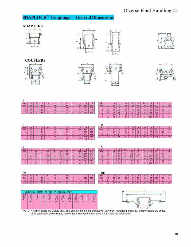
SNAPLOCK® Couplings - General Dimensions
ADAPTERS
COUPLERS
A D Size ½ ¾ 1 1 ¼ 1 ½ 2 2½ 3 4 5 6 Size ½ ¾ 1 1¼ 1½ 2 2½ 3 4 5 6 Dim 13 19 25 32 40 50 65 75 100 125 150 Dim 13 19 25 32 40 50 65 75 100 125 150
A 13 20 24 28 35 45 55 72 97 121 145 A 14 21 25 30 36 46 56 73 101 121 141 B 37 41 46 55 58 62 89 71 80 85 89 B 48 53 60 70 74 81 87 90 100 102 108 C 26 35 38 47 56 69 82 101 126 150 182 C 26 34 40 51 57 68 82 98 124 152 181
E 32 35 39 46 47 54 57 59 61 63 68 G 39 54 59 70 80 89 105 121 150 180 220
F BSize ½ ¾ 1 1¼ 1½ 2 2½ 3 4 5 6 Size ½ ¾ 1 1¼ 1½ 2 2½ 3 4 5 6 Dim 13 19 25 32 40 50 65 75 100 125 150 Dim 13 19 25 32 40 50 65 75 100 125 150
A 13 21 25 28 36 45 55 72 96 124 151 A 14 19 23 30 36 47 60 72 100 123 150 B 56 59 68 78 81 87 101 103 118 127 121 B 47 54 62 68 72 79 87 91 99 103 113 C 26 35 38 47 56 68 79 101 126 150 181 G 39 54 60 80 81 89 105 90 148 175 220 E 37 41 45 54 58 62 69 71 79 82 78
E CSize ½ ¾ 1 1¼ 1½ 2 2½ 3 4 5 6 Size ½ ¾ 1 1¼ 1½ 2 2½ 3 4 5 6 Dim 13 19 25 32 40 50 65 75 100 125 150 Dim 13 19 25 32 40 50 65 75 100 125 150
A 14 20 25 28 36 45 55 72 96 120 143 A 10 13 19 26 32 43 56 66 90 106 144 B 64 84 93 104 110 128 135 160 168 193 243 B 73 87 97 104 109 125 136 160 170 187 256 C 29 35 38 49 58 76 79 98 122 162 178 D 15 21 27 33 41 53 68 76 103 130 155 D 15 21 27 34 40 53 66 78 102 126 152 E 31 35 40 46 47 53 56 58 62 65 66 E 29 34 37 46 49 57 57 58 60 71 76 G 39 54 60 79 86 97 105 121 148 175 220
DP DCSize ½ ¾ 1 1¼ 1½ 2 2½ 3 4 5 6 Size ½ ¾ 1 1¼ 1½ 2 2½ 3 4 5 6 Dim 13 19 25 32 40 50 65 75 100 125 150 Dim 13 19 25 32 40 50 65 75 100 125 150
B 36 38 46 53 55 63 68 66 70 75 88 B 43 46 52 60 63 70 73 78 90 105 113 E 27 25 34 41 41 49 53 52 54 53 90 G 39 54 59 70 80 89 105 121 150 180 220
OVERALL WIDTH WITH HANDLES OPEN Size ½ ¾ 1 1¼ 1½ 2 2½ 3 4 5 6 Dim 13 19 25 32 40 50 65 75 100 125 150 H 149 157 180 235 245 254 267 311 340 368 487 J 103 111 140 182 189 200 211 248 276 305 419
NOTE: All dimensions are typical only. The precise dimension of parts will vary from material to material. If dimensions are critical to an application, we strongly recommend that you contact us to obtain detailed information.
Clark Beesley
New Stamp
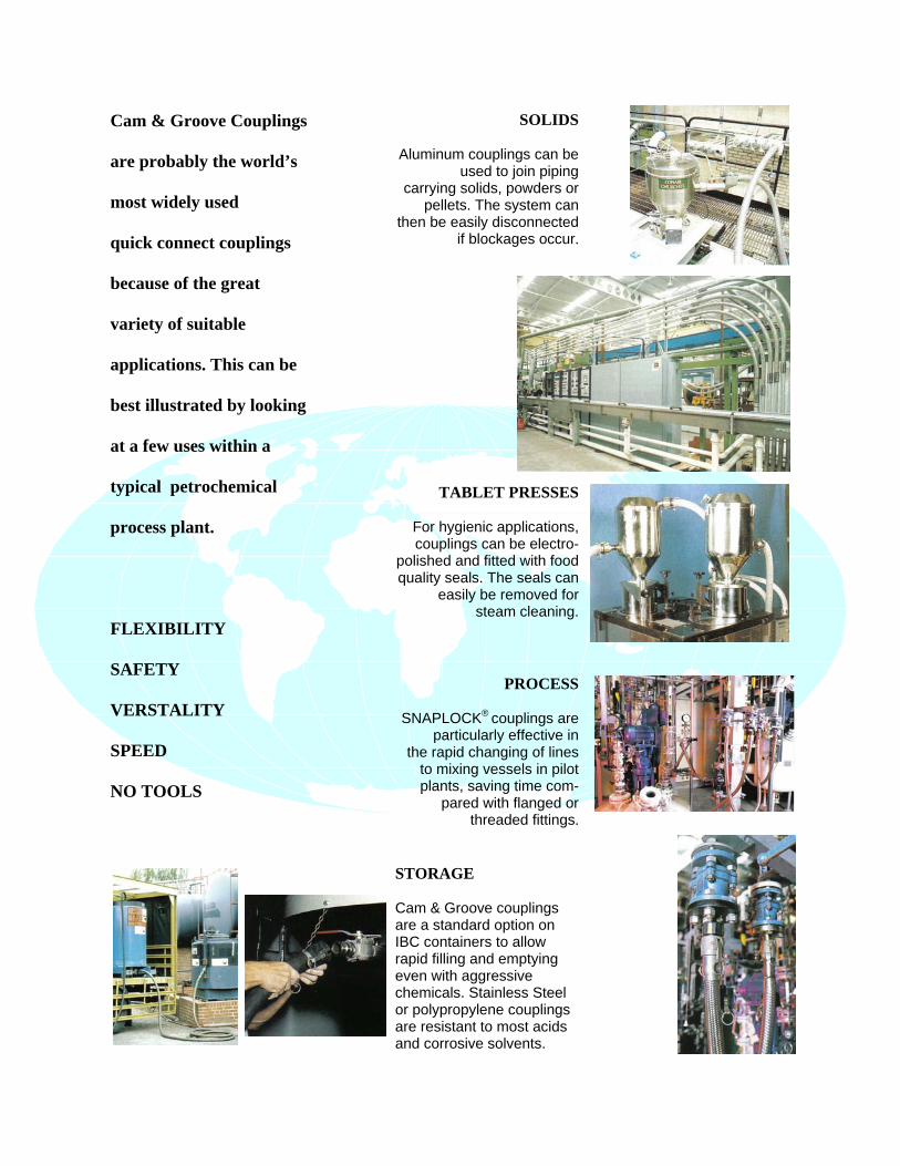
Cam & Groove Couplings
are probably the world’s
most widely used
quick connect couplings
because of the great
variety of suitable
applications. This can be
best illustrated by looking
at a few uses within a
typical petrochemical
process plant.
FLEXIBILITY
SAFETY
VERSTALITY
SPEED
NO TOOLS
SOLIDS
Aluminum couplings can be used to join piping
carrying solids, powders or pellets. The system can
then be easily disconnected if blockages occur.
TABLET PRESSES
For hygienic applications, couplings can be electro-
polished and fitted with food quality seals. The seals can
easily be removed for steam cleaning.
PROCESS
SNAPLOCK® couplings are particularly effective in
the rapid changing of lines to mixing vessels in pilot plants, saving time com-
pared with flanged or threaded fittings.
STORAGE
Cam & Groove couplings are a standard option on IBC containers to allow rapid filling and emptying even with aggressive chemicals. Stainless Steel or polypropylene couplings are resistant to most acids and corrosive solvents.
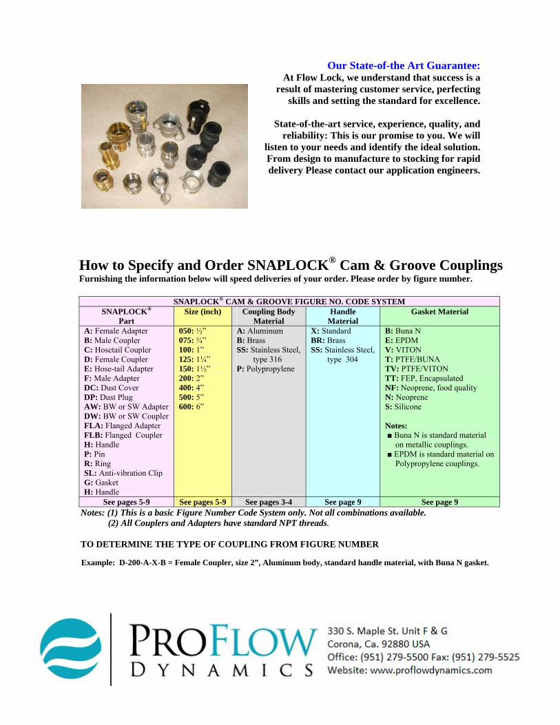
How to Specify and Order SNAPLOCK® Cam & Groove Couplings Furnishing the information below will speed deliveries of your order. Please order by figure number.
SNAPLOCK® CAM & GROOVE FIGURE NO. CODE SYSTEM SNAPLOCK®
Part Size (inch) Coupling Body
Material Handle
Material Gasket Material
A: Female Adapter B: Male Coupler C: Hosetail Coupler D: Female Coupler E: Hose-tail Adapter F: Male Adapter DC: Dust Cover DP: Dust Plug AW: BW or SW Adapter DW: BW or SW Coupler FLA: Flanged Adapter FLB: Flanged Coupler H: Handle P: Pin R: Ring SL: Anti-vibration Clip G: Gasket H: Handle
050: ½” 075: ¾” 100: 1” 125: 1¼” 150: 1½” 200: 2” 400: 4” 500: 5” 600: 6”
A: Aluminum B: Brass SS: Stainless Steel, type 316 P: Polypropylene
X: Standard BR: Brass SS: Stainless Steel,
type 304
B: Buna N E: EPDM V: VITON T: PTFE/BUNA TV: PTFE/VITON TT: FEP, Encapsulated NF: Neoprene, food quality N: Neoprene S: Silicone
Notes: ■ Buna N is standard material
on metallic couplings.■ EPDM is standard material on
Polypropylene couplings.
See pages 5-9 See pages 5-9 See pages 3-4 See page 9 See page 9 Notes: (1) This is a basic Figure Number Code System only. Not all combinations available.
(2) All Couplers and Adapters have standard NPT threads.
TO DETERMINE THE TYPE OF COUPLING FROM FIGURE NUMBER
Example: D-200-A-X-B = Female Coupler, size 2”, Aluminum body, standard handle material, with Buna N gasket.
Our State-of-the Art Guarantee: At Flow Lock, we understand that success is a
result of mastering customer service, perfecting skills and setting the standard for excellence.
State-of-the-art service, experience, quality, and reliability: This is our promise to you. We will
listen to your needs and identify the ideal solution. From design to manufacture to stocking for rapid delivery Please contact our application engineers.
Clark Beesley
PFD logo n address correct ver