Camera Calibration - Inspiring InnovationCamera Calibration ! Goal: build the geometric relations...
37
Jesus J Caban Camera Calibration Schedule ! Today: ! Camera calibration ! Wednesday: ! Lecture: Motion & Optical Flow ! Monday: ! Lecture: Medical Imaging ! Final presentations: ! Nov 29 th : W. Griffin ! Dec 1 st : F. Zafar,Y. Wang, and N. Chhaya ! Dec 6 th : J. Dandois ! Dec 8 th : ! Dec 13 th : ! Dec 20 th : +5 bonus points +3 bonus points +2 bonus points +1 bonus points +0 bonus points +0 bonus points Note:You have until next Monday to let me know…
Transcript of Camera Calibration - Inspiring InnovationCamera Calibration ! Goal: build the geometric relations...

Jesus J Caban
Camera Calibration
Schedule ! Today:
! Camera calibration
! Wednesday: ! Lecture: Motion & Optical Flow
! Monday: ! Lecture: Medical Imaging
! Final presentations: ! Nov 29th: W. Griffin ! Dec 1st: F. Zafar, Y. Wang, and N. Chhaya ! Dec 6th: J. Dandois ! Dec 8th: ! Dec 13th: ! Dec 20th:
+5 bonus points +3 bonus points
+2 bonus points
+1 bonus points
+0 bonus points +0 bonus points
Note: You have until next Monday to let me know…
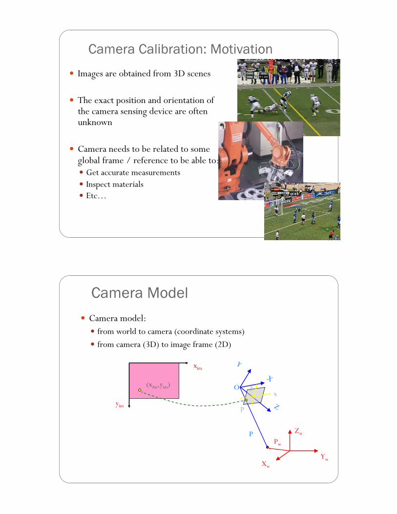
Camera Calibration: Motivation ! Images are obtained from 3D scenes
! The exact position and orientation of the camera sensing device are often unknown
! Camera needs to be related to some global frame / reference to be able to: ! Get accurate measurements ! Inspect materials ! Etc…
Camera Model ! Camera model:
! from world to camera (coordinate systems) ! from camera (3D) to image frame (2D)
Zw
Xw
Yw
Pw
O
P
x y
p
xim
yim
(xim,yim)
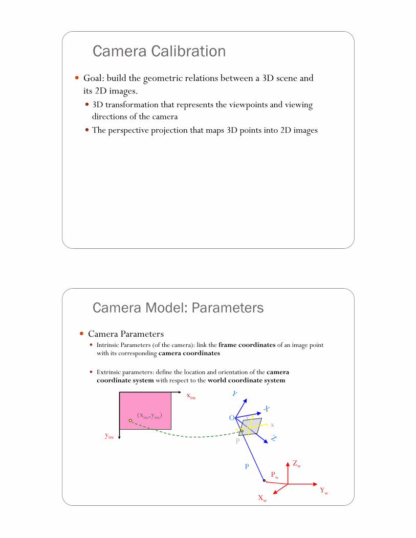
Camera Calibration ! Goal: build the geometric relations between a 3D scene and
its 2D images. ! 3D transformation that represents the viewpoints and viewing
directions of the camera ! The perspective projection that maps 3D points into 2D images
Camera Model: Parameters
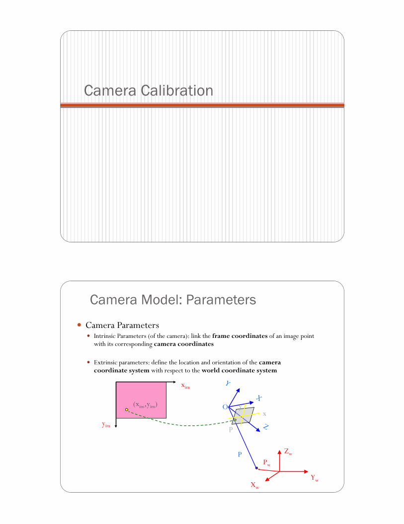
! Camera Parameters ! Intrinsic Parameters (of the camera): link the frame coordinates of an image point
with its corresponding camera coordinates
! Extrinsic parameters: define the location and orientation of the camera coordinate system with respect to the world coordinate system
Zw
Xw
Yw
Pw
O
P
x y
p
xim
yim
(xim,yim)
Transformations
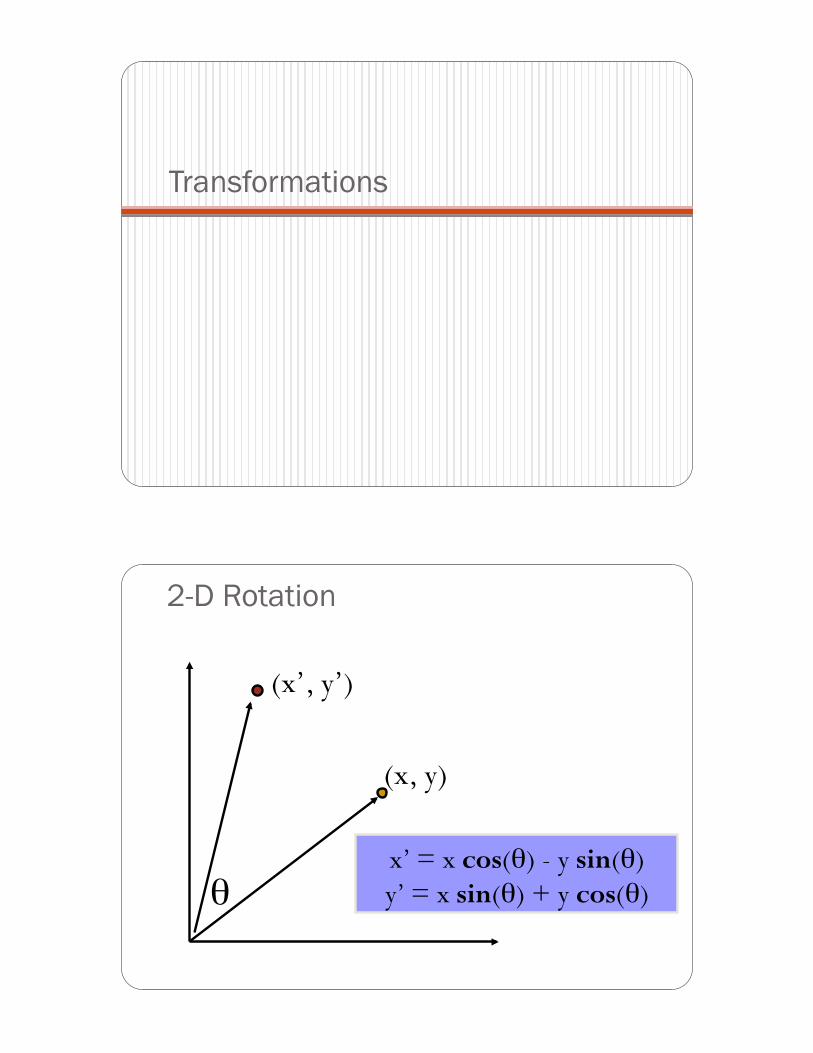
2-D Rotation
!
(x, y)
(x’, y’)
x’ = x cos(!) - y sin(!) y’ = x sin(!) + y cos(!)
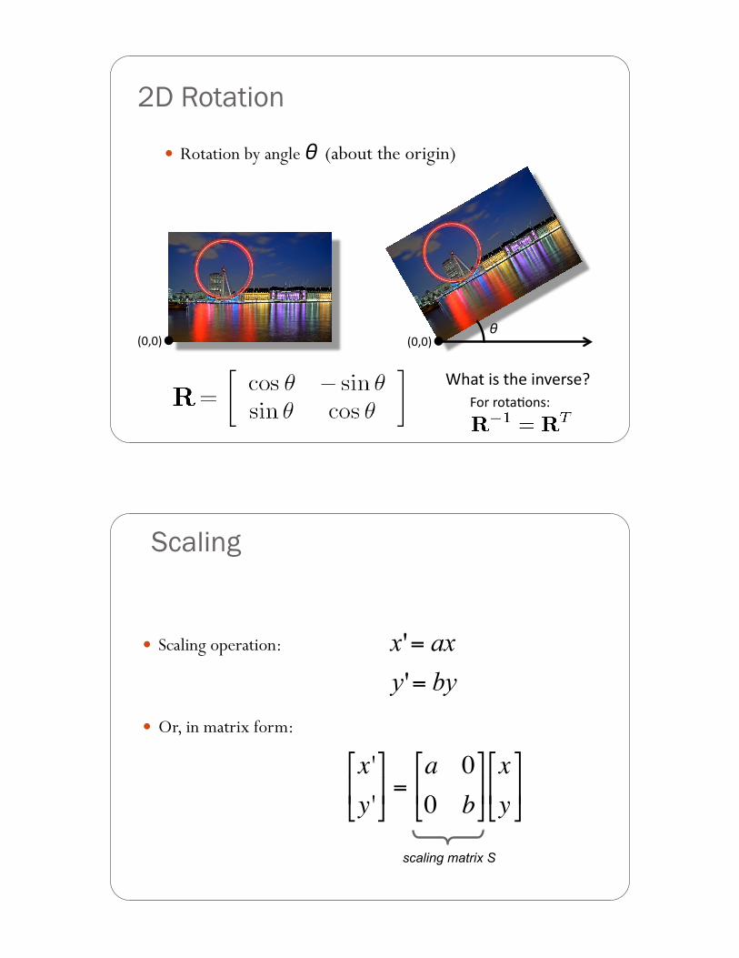
2D Rotation
! Rotation by angle ! (about the origin)
!"#"$% !"#"$%
&'()%*+%)',%*-.,/+,0%12/%/2)(32-+4%
!%
Scaling
! Scaling operation:
! Or, in matrix form:
!
x 'y '"
# $ %
& ' =
a 00 b"
# $
%
& ' xy"
# $ %
& '
scaling matrix S
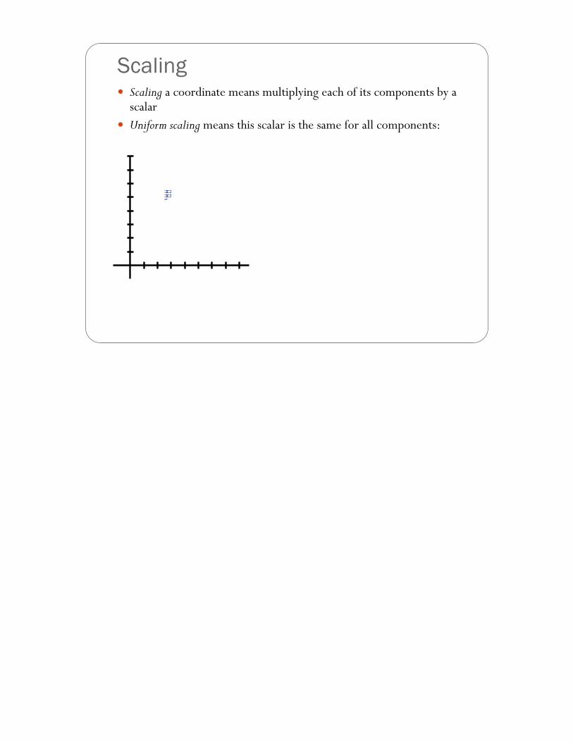
Scaling ! Scaling a coordinate means multiplying each of its components by a
scalar ! Uniform scaling means this scalar is the same for all components:
" 2
Scaling
! Uniform scaling by s:
!"#"$% !"#"$%
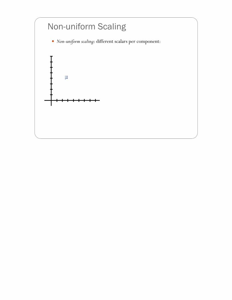
! Non-uniform scaling: different scalars per component:
Non-uniform Scaling
X " 2, Y " 0.5
2x2 Matrices
! What types of transformations can be represented with a 2x2 matrix?
2D Mirror about Y axis?
2D Mirror over (0,0)?
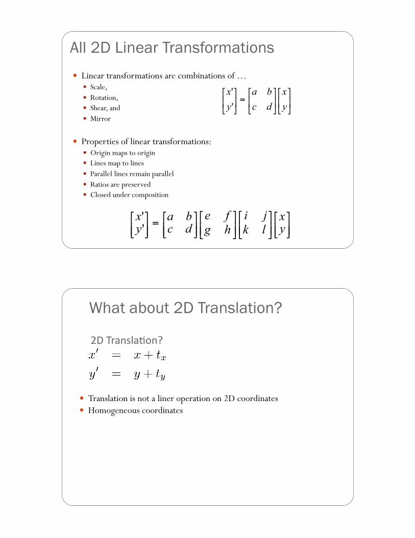
All 2D Linear Transformations ! Linear transformations are combinations of …
! Scale, ! Rotation, ! Shear, and ! Mirror
! Properties of linear transformations: ! Origin maps to origin ! Lines map to lines ! Parallel lines remain parallel ! Ratios are preserved ! Closed under composition
! Translation is not a liner operation on 2D coordinates ! Homogeneous coordinates
56%7/(-+8(32-0%
What about 2D Translation?
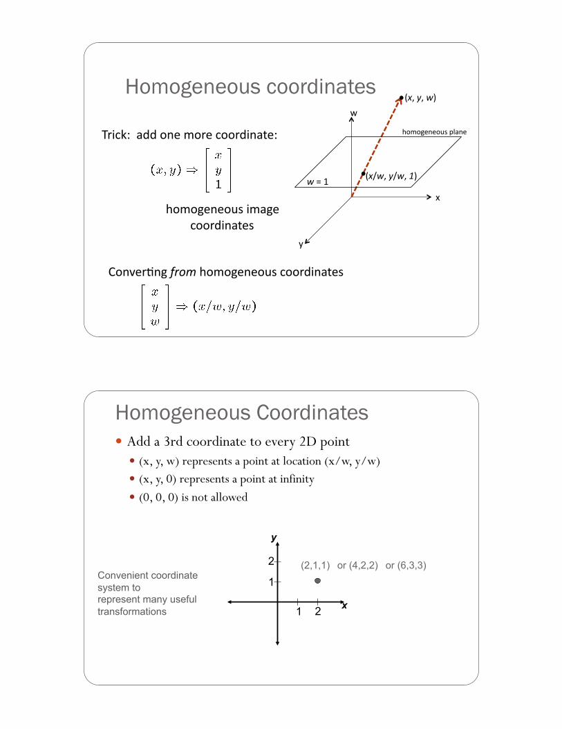
Homogeneous coordinates
7/*9:4%%(;;%2-,%<2/,%922/;*-(),4%
'2<2=,-,2>+%*<(=,%%922/;*-(),+%
?2-.,/3-=%!"#$%'2<2=,-,2>+%922/;*-(),+%
@%
A%
B%
!%#%&#%'$%
'%C%D% !%E'#%&E'#%($%
'2<2=,-,2>+%F8(-,%
Homogeneous Coordinates ! Add a 3rd coordinate to every 2D point
! (x, y, w) represents a point at location (x/w, y/w) ! (x, y, 0) represents a point at infinity ! (0, 0, 0) is not allowed
Convenient coordinate system to represent many useful transformations 1 2
1
2 (2,1,1) or (4,2,2) or (6,3,3)
x
y
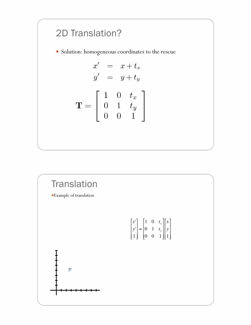
2D Translation?
! Solution: homogeneous coordinates to the rescue
Translation ! Example of translation
!
x 'y '1
"
#
$ $ $
%
&
' ' '
=
1 0 tx0 1 ty0 0 1
"
#
$ $ $
%
&
' ' '
xy1
"
#
$ $ $
%
&
' ' '
tx = 2 ty = 1
Homogeneous Coordinates
!
=
x + txy + ty1
"
#
$ $ $
%
&
' ' '
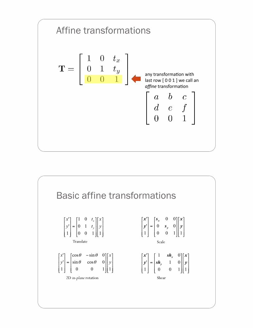
Affine transformations
(-A%)/(-+G2/<(32-%B*)'%%8(+)%/2B%H%"%"%D%I%B,%9(88%(-%%)*+,%)/(-+G2/<(32--
Basic affine transformations
Translate
2D in-plane rotation Shear
Scale
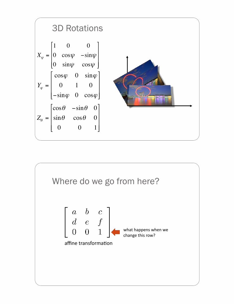
3D Rotations
!
Z" =
cos" #sin" 0sin" cos" 00 0 1
$
%
& & &
'
(
) ) )
!
X" =
1 0 00 cos" #sin"0 sin" cos"
$
%
& & &
'
(
) ) )
!
Y" =
cos" 0 sin"0 1 0
#sin" 0 cos"
$
%
& & &
'
(
) ) )
Where do we go from here?
(J-,%)/(-+G2/<(32-%
B'()%'(FF,-+%B',-%B,%9'(-=,%)'*+%/2B0-
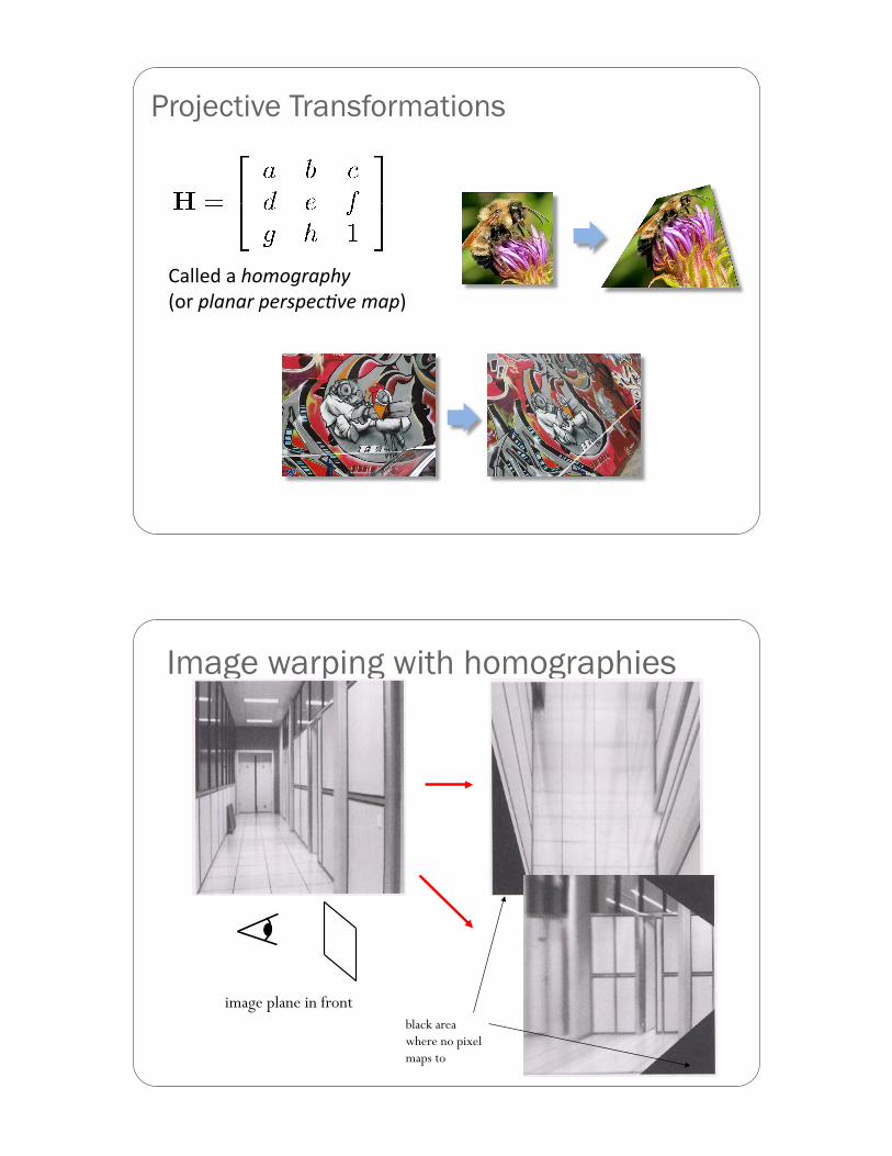
Projective Transformations
?(88,;%(%.#$#/")0.&%%!2/%01)+)"-0,"20,345,-$)0$-
Image warping with homographies
image plane in front image plane below black area where no pixel maps to
Camera Calibration
Camera Model: Parameters
! Camera Parameters ! Intrinsic Parameters (of the camera): link the frame coordinates of an image point
with its corresponding camera coordinates
! Extrinsic parameters: define the location and orientation of the camera coordinate system with respect to the world coordinate system
Zw
Xw
Yw
Pw
O
P
x y
p
xim
yim
(xim,yim)
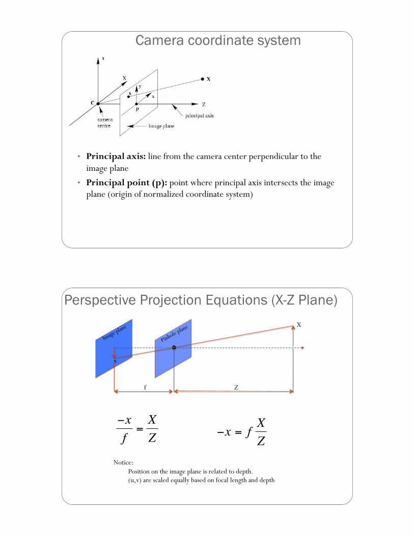
Camera coordinate system
• Principal axis: line from the camera center perpendicular to the image plane
• Principal point (p): point where principal axis intersects the image plane (origin of normalized coordinate system)
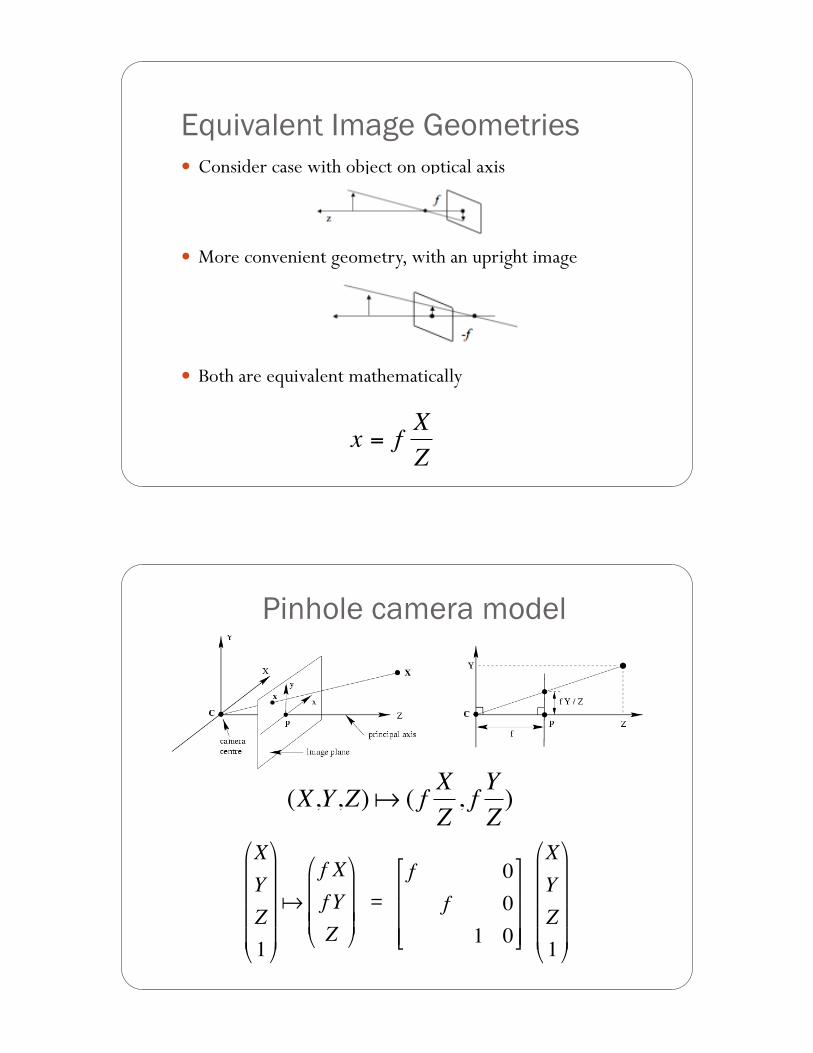
Perspective Projection Equations (X-Z Plane) X
x
Z f
!
"xf
=XZ
!
"x = fXZ
Notice: Position on the image plane is related to depth. (u,v) are scaled equally based on focal length and depth
Equivalent Image Geometries ! Consider case with object on optical axis
! More convenient geometry, with an upright image
! Both are equivalent mathematically
!
x = fXZ
!
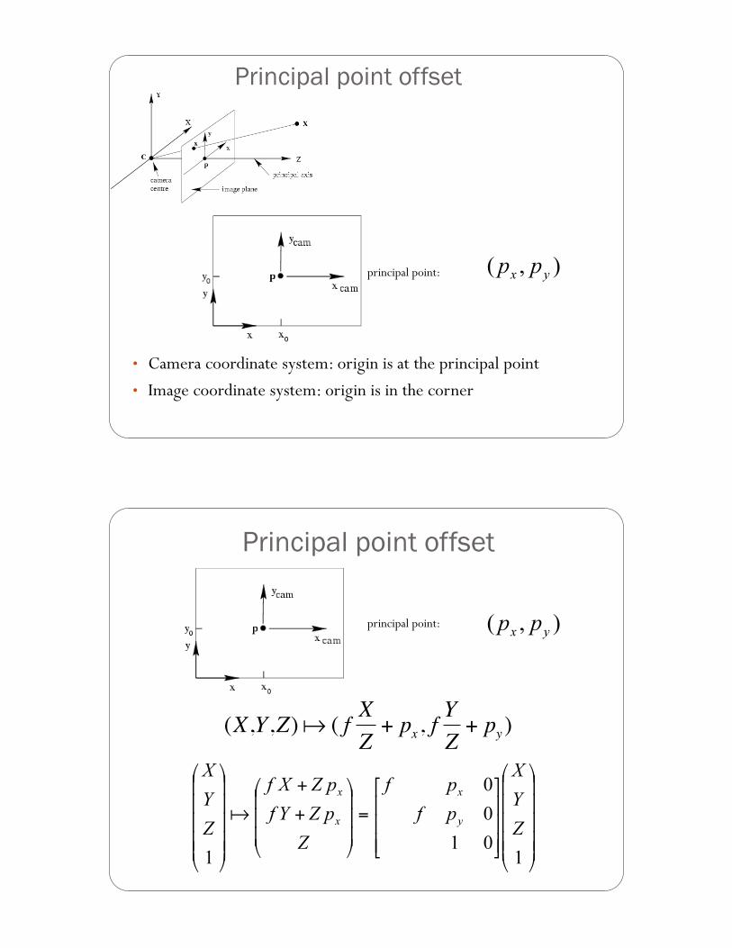
(X,Y,Z)! ( f XZ, f YZ)
!
XYZ1
"
#
$ $ $ $
%
&
' ' ' '
!f Xf YZ
"
#
$ $ $
%
&
' ' '
Pinhole camera model
!
XYZ1
"
#
$ $ $ $
%
&
' ' ' '
!
f 0f 01 0
"
#
$ $ $
%
&
' ' '
=
Principal point offset
• Camera coordinate system: origin is at the principal point • Image coordinate system: origin is in the corner
principal point:
!
(X,Y,Z)! ( f XZ
+ px, fYZ
+ py )
Principal point offset
principal point:
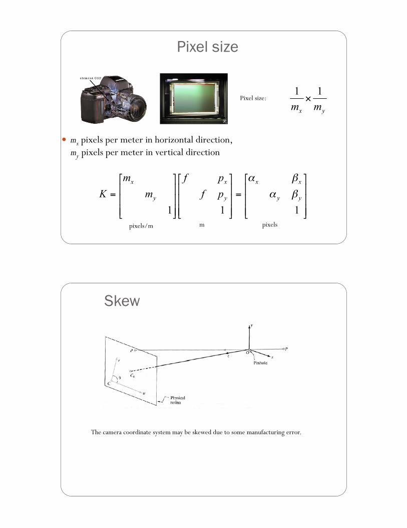
Pixel size
! mx pixels per meter in horizontal direction, my pixels per meter in vertical direction
Pixel size:
pixels/m m pixels
Skew
The camera coordinate system may be skewed due to some manufacturing error.
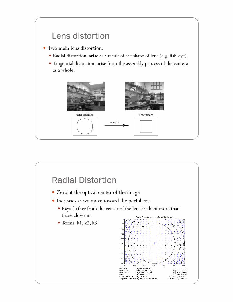
Lens distortion ! Two main lens distortion:
! Radial distortion: arise as a result of the shape of lens (e.g. fish-eye) ! Tangential distortion: arise from the assembly process of the camera
as a whole.
Radial Distortion ! Zero at the optical center of the image ! Increases as we move toward the periphery
! Rays farther from the center of the lens are bent more than those closer in
! Terms: k1, k2, k3
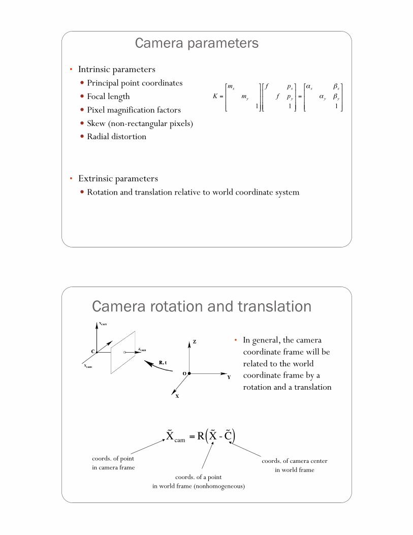
Camera parameters
• Intrinsic parameters ! Principal point coordinates ! Focal length ! Pixel magnification factors ! Skew (non-rectangular pixels) ! Radial distortion
• Extrinsic parameters ! Rotation and translation relative to world coordinate system
!
˜ X cam = R ˜ X - ˜ C ( )
Camera rotation and translation
• In general, the camera coordinate frame will be related to the world coordinate frame by a rotation and a translation
coords. of point in camera frame
coords. of camera center in world frame
coords. of a point in world frame (nonhomogeneous)
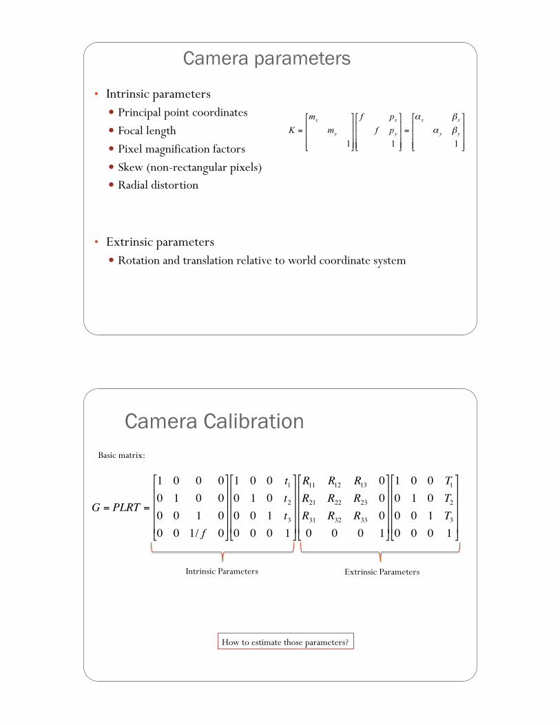
Camera parameters
• Intrinsic parameters ! Principal point coordinates ! Focal length ! Pixel magnification factors ! Skew (non-rectangular pixels) ! Radial distortion
• Extrinsic parameters ! Rotation and translation relative to world coordinate system
Camera Calibration
!
G = PLRT =
1 0 0 00 1 0 00 0 1 00 0 1/ f 0
"
#
$ $ $ $
%
&
' ' ' '
1 0 0 t10 1 0 t20 0 1 t30 0 0 1
"
#
$ $ $ $
%
&
' ' ' '
R11 R12 R13 0R21 R22 R23 0R31 R32 R33 00 0 0 1
"
#
$ $ $ $
%
&
' ' ' '
1 0 0 T10 1 0 T20 0 1 T30 0 0 1
"
#
$ $ $ $
%
&
' ' ' '
Intrinsic Parameters Extrinsic Parameters
Basic matrix:
How to estimate those parameters?
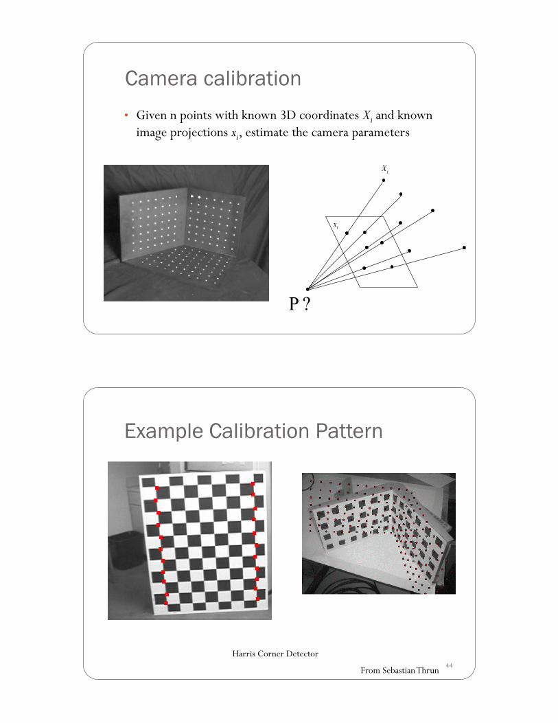
Camera calibration • Given n points with known 3D coordinates Xi and known
image projections xi, estimate the camera parameters
Xi
xi
44
Example Calibration Pattern
From Sebastian Thrun
Harris Corner Detector
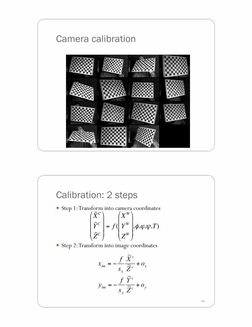
Camera calibration
46
Calibration: 2 steps ! Step 1: Transform into camera coordinates
! Step 2: Transform into image coordinates
!
˜ X C
˜ Y C
˜ Z C
"
#
$ $ $
%
&
' ' '
= f (XW
Y W
ZW
"
#
$ $ $
%
&
' ' ' ,(,),*,T)
47
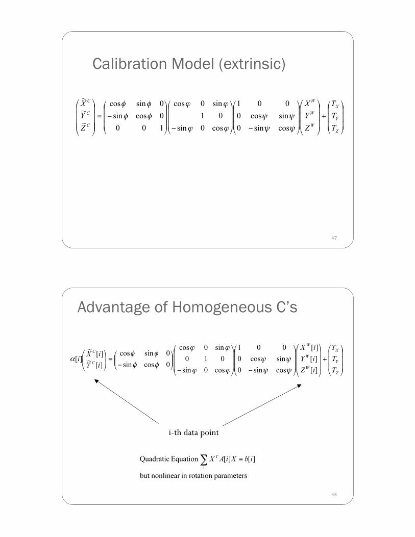
Calibration Model (extrinsic)
48
Advantage of Homogeneous C’s
i-th data point
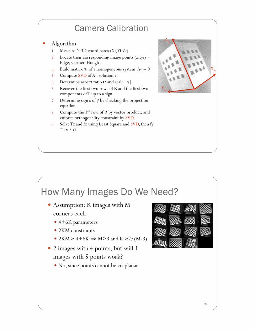
Camera Calibration ! Algorithm
1. Measure N 3D coordinates (Xi, Yi,Zi) 2. Locate their corresponding image points (xi,yi) -
Edge, Corner, Hough 3. Build matrix A of a homogeneous system Av = 0 4. Compute SVD of A , solution v 5. Determine aspect ratio # and scale |$| 6. Recover the first two rows of R and the first two
components of T up to a sign 7. Determine sign s of $ by checking the projection
equation 8. Compute the 3rd row of R by vector product, and
enforce orthogonality constraint by SVD 9. Solve Tz and fx using Least Square and SVD, then fy
= fx / #%
Yw
Xw
Zw
50
How Many Images Do We Need? ! Assumption: K images with M
corners each ! 4+6K parameters ! 2KM constraints ! 2KM & 4+6K ' M>3 and K &2/(M-3)
! 2 images with 4 points, but will 1 images with 5 points work? ! No, since points cannot be co-planar!
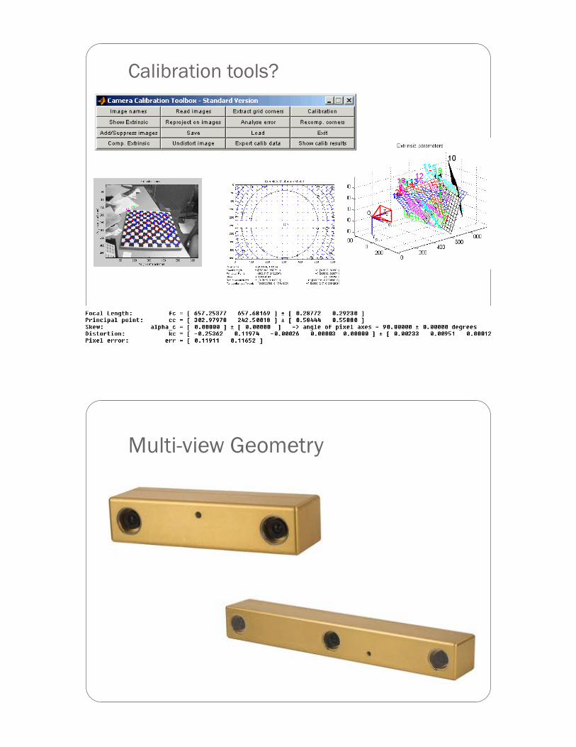
Calibration tools?
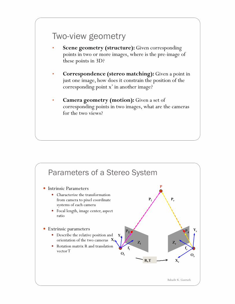
Multi-view Geometry
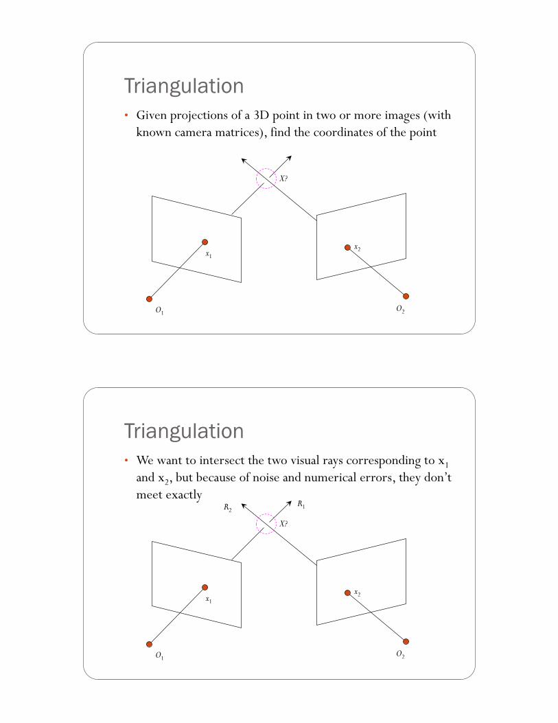
Two-view geometry • Scene geometry (structure): Given corresponding
points in two or more images, where is the pre-image of these points in 3D?
• Correspondence (stereo matching): Given a point in just one image, how does it constrain the position of the corresponding point x’ in another image?
• Camera geometry (motion): Given a set of corresponding points in two images, what are the cameras for the two views?
Bahadir K. Gunturk
Parameters of a Stereo System
! Intrinsic Parameters ! Characterize the transformation
from camera to pixel coordinate systems of each camera
! Focal length, image center, aspect ratio
! Extrinsic parameters ! Describe the relative position and
orientation of the two cameras ! Rotation matrix R and translation
vector T
p l p
r
P
Ol Or
Xl
Xr
Pl Pr
fl fr
Zl
Yl
Zr
Yr
R, T
Triangulation • Given projections of a 3D point in two or more images (with
known camera matrices), find the coordinates of the point
O1 O2
x1 x2
X?
Triangulation • We want to intersect the two visual rays corresponding to x1
and x2, but because of noise and numerical errors, they don’t meet exactly
O1 O2
x1 x2
X?
R1 R2
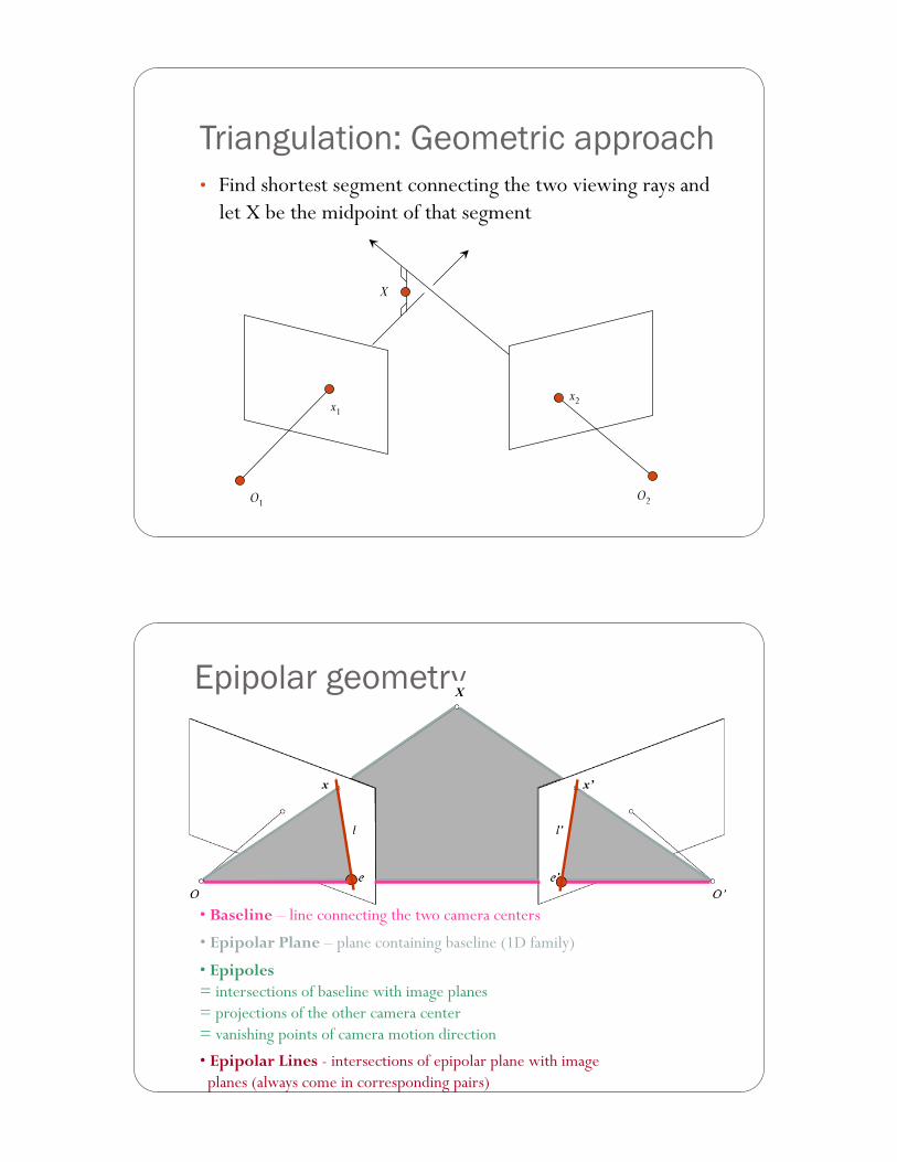
Triangulation: Geometric approach • Find shortest segment connecting the two viewing rays and
let X be the midpoint of that segment
O1 O2
x1 x2
X
• Epipolar Plane – plane containing baseline (1D family)
• Epipoles = intersections of baseline with image planes = projections of the other camera center = vanishing points of camera motion direction
• Epipolar Lines - intersections of epipolar plane with image planes (always come in corresponding pairs)
• Baseline – line connecting the two camera centers
Epipolar geometry X
x x’
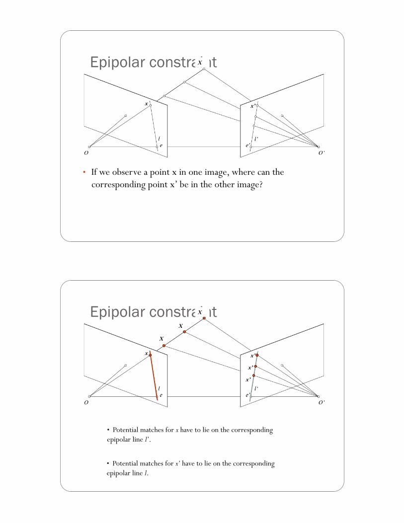
Epipolar constraint
• If we observe a point x in one image, where can the corresponding point x’ be in the other image?
x x’
X
• Potential matches for x have to lie on the corresponding epipolar line l’.
• Potential matches for x’ have to lie on the corresponding epipolar line l.
Epipolar constraint
x x’
X
x’
X
x’
X
Bahadir K. Gunturk
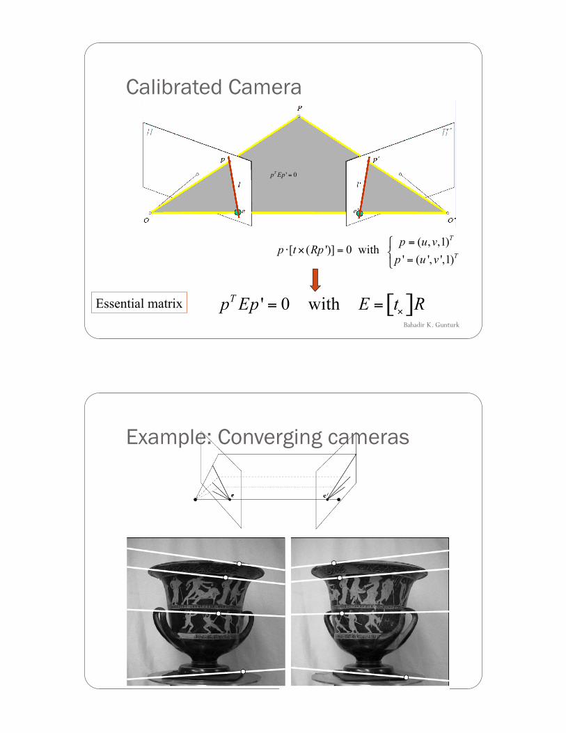
Calibrated Camera
Essential matrix
Example: Converging cameras
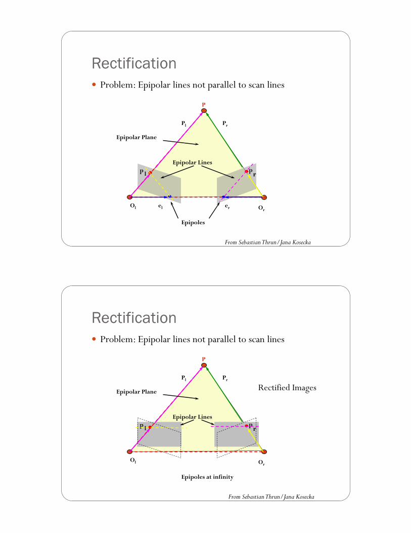
Rectification ! Problem: Epipolar lines not parallel to scan lines
p l p r
P
Ol Or el er
Pl Pr
Epipolar Plane
Epipolar Lines
Epipoles
From Sebastian Thrun/Jana Kosecka
Rectification ! Problem: Epipolar lines not parallel to scan lines
p l p r
P
Ol Or
Pl Pr
Epipolar Plane
Epipolar Lines
Epipoles at infinity
Rectified Images
From Sebastian Thrun/Jana Kosecka
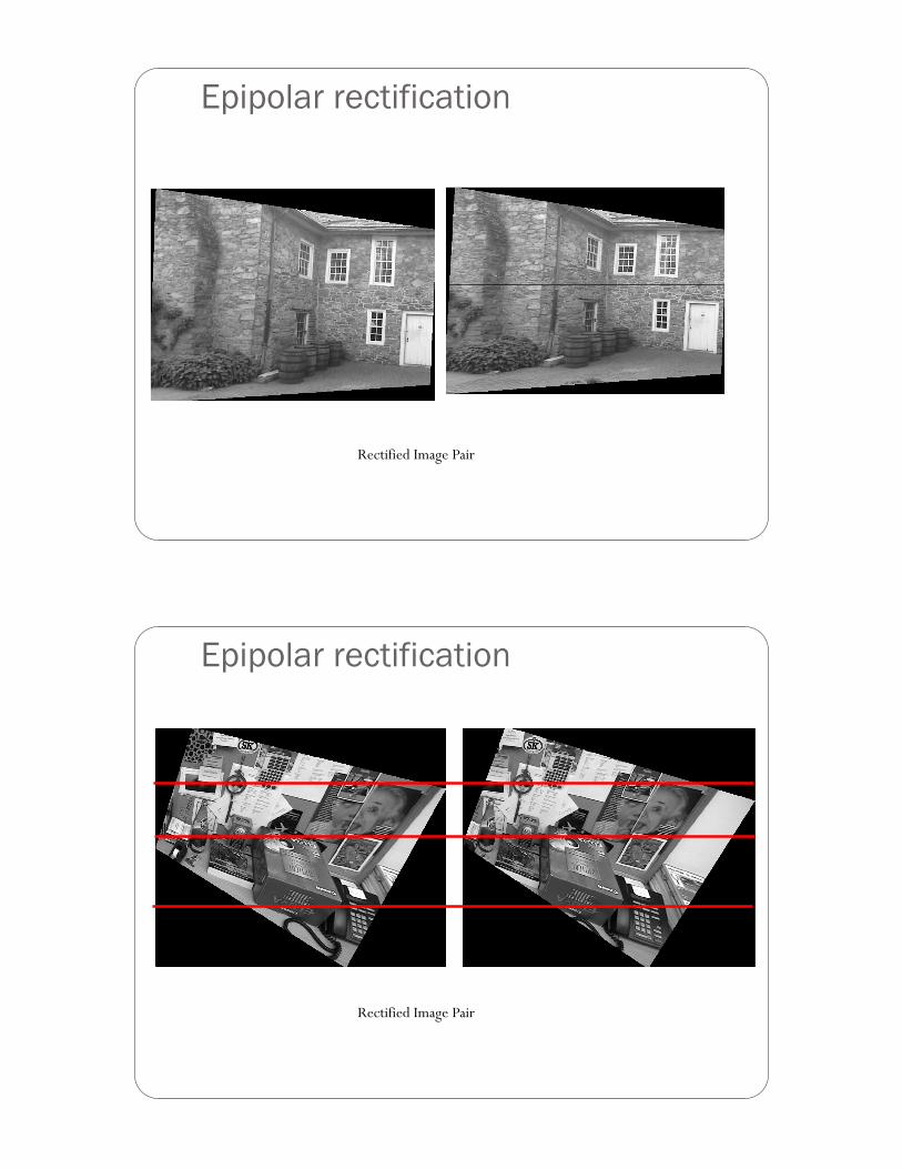
Epipolar rectification
Rectified Image Pair
Epipolar rectification
Rectified Image Pair
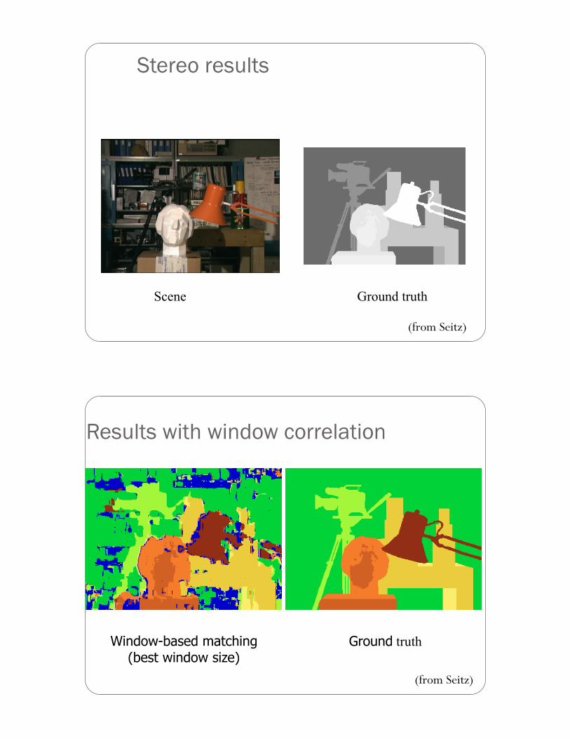
Stereo results
Ground truth Scene
(from Seitz)
Results with window correlation
Window-based matching (best window size)
Ground truth
(from Seitz)
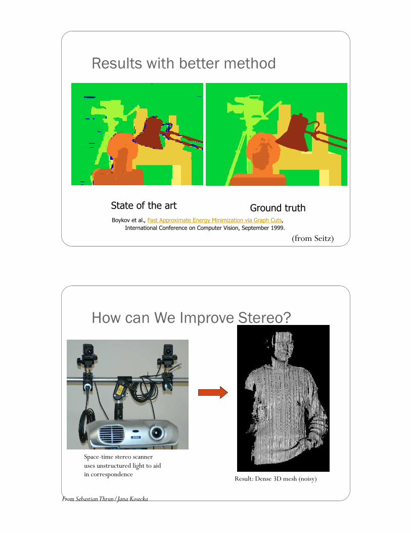
Results with better method
Boykov et al., Fast Approximate Energy Minimization via Graph Cuts, International Conference on Computer Vision, September 1999.
(from Seitz)
Ground truth State of the art
How can We Improve Stereo?
Space-time stereo scanner uses unstructured light to aid in correspondence
Result: Dense 3D mesh (noisy)
From Sebastian Thrun/Jana Kosecka
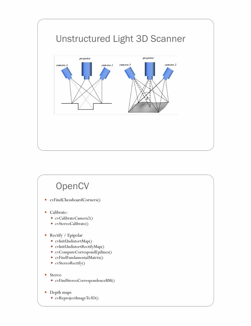
Unstructured Light 3D Scanner
OpenCV ! cvFindChessboardCorners()
! Calibrate: ! cvCalibrateCamera2() ! cvStereoCalibrate()
! Rectify / Epipolar ! cvInitUndistortMap() ! cvInitUndistortRectifyMap() ! cvComputeCorrespondEpilines() ! cvFindFundamentalMatrix() ! cvStereoRectify()
! Stereo ! cvFindStereoCorrespondenceBM()
! Depth maps ! cvReprojectImageTo3D()
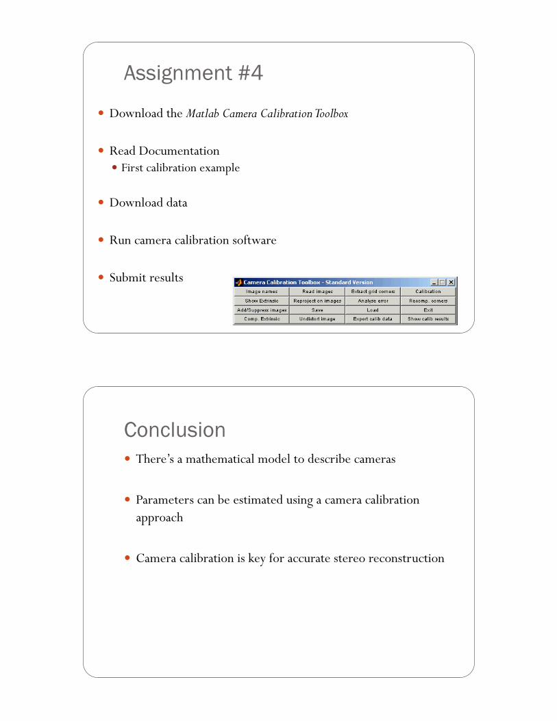
Assignment #4
! Download the Matlab Camera Calibration Toolbox
! Read Documentation ! First calibration example
! Download data
! Run camera calibration software
! Submit results
Conclusion ! There’s a mathematical model to describe cameras
! Parameters can be estimated using a camera calibration approach
! Camera calibration is key for accurate stereo reconstruction