Cambridge Wall Book v09 Wall Section.pdf · 40 cambridge wall book 41 backyard patios & outdoor...
23
BACKYARD PATIOS & OUTDOOR LIVING ROOMS • PAVINGSTONES • WALL SYSTEMS SIGMA WALL 6” AND 8” SIGMA FIND MORE DETAILS AT RETAINING WALL cambridgewallsupport.com cambridgepavers.com
Transcript of Cambridge Wall Book v09 Wall Section.pdf · 40 cambridge wall book 41 backyard patios & outdoor...

40 41Cambridge Wall Book
BACKYARD PATIOS & OUTDOOR LIVING ROOMS • PAVINGSTONES • WALL SYSTEMS
SIGMA WALL
6” AND 8” SIGMA
FIND MORE DETAILS AT
RETAINING WALLcambridgewallsupport.comcambridgepavers.com

42 43Cambridge Wall Book
W Sigma™Cambridge
Wall Systemfor Engineered Walls

42 43Cambridge Wall Book
SigmaTM Wallstones
Developed for the large, commercial Segmental Retaining Wall (SRW) market, Sigma single-sided wallstones provide advantages for smaller and larger residential wall projects as well. The system, available in Split Face and Renaissance in 6” and 8” heights with right and left manufactured corners, is especially ideal for taller, engineered retaining walls as shown. The hexagonal con� guration allows for a wall design with a very tight radius.
AVAILABLE COLORS See Page 108 for color swatches. For color availability, refer to Page 104.
Cambridge Curbstone
Achieve the look of Belgian block with this affordable, durable alternative to plastic edge restraints, aluminum and wood edging as well as concrete curb or toe.
Curbstone 9” x 8” x 3 1/2”
THE SIGMA WALL SHAPES
Sigma 8” Split Face 8” High 12” Deep 18” Long
Sigma 6” Split Face 6” High 12” Deep 16” Long
Sigma 6” & 8” Corner Split Face 6” High or 8” High Both 14” Deep Both 8” Long
Cambridge Edgestone
Ideal as edging for mulch beds, gardens, decorative gravel and more in lieu of concrete, clay brick, molded plastic and wood edging.
Edgestone 8” x 6” x 2 3/8”
For color availability of any of the shapes above, refer to the Color Selection Guide on Page 104.

44 45Cambridge Wall Book
The Cambridge Sigma Wall System is built to the highest standards in height, texture, color and ease of use. The Sigma system was designed from contractor feedback. Professional Installers asked for a stone that would not hurt their back, a connection system that was simple to use with no pins, a large wall system that matched our Maytrx and Outdoor Living Kits and a wall that looked good in a residential backyard.
The Sigma 6 incorporates our patent pending Double Knob System. It installs as delivered with a 6 degree setback, or by knocking off the front set of “break away” knobs to get “near vertical” alignment. The NEW Sigma line includes large corner stones that create a great looking, strong corner. And as a bonus, every Sigma Stone has the ability to create two “emergency” stub (smaller) corners for that small job.
SIGMA RETAINING WALL SIGMA

44 45Cambridge Wall Book
INDEXSIGMAWhy Use this Sigma stone System?
• Extremely light, saves your back, increases productivity, saves on trucking• Highest Standard for height and quality• Effervescence not an issue• Color and texture matches a full line of Outdoor Living building products including paving stones and Kits including Firepits,
Kitchens, Fireplaces• No Pins needed• Ability to get two “Stub” corners from one stone if needed on small jobs• Matching Columns made with the Sigma Corners, no cutting, many cap options available• Matches the Maytrx System in Look, Color and Texture• Build to any engineered height• Free project takeoff with cross section drawing and materials list is available from our SRW partner• Low cost “Stamped” drawings available in your state• Engineering, getting started and design guides available for download or viewing on tablet or phone• Large Corner stones available for good interlock in small packages• Single and double sided Caps are available• Most colors available in Split face or Renaissance• Simple to install; Knobs � t in the cavity of the stones below and then pull the stone forward• Comes in 6” and 8” heights (Sigma 6 (16” long ) and Sigma 8 (18” long)• Sigma 6 has a set of “break away” knobs that allow near vertical with same stone
Contractors love it to install, Customers love the look.Easy to Make steps stone is � at on top when set on stone below.
46 47Cambridge Wall Book
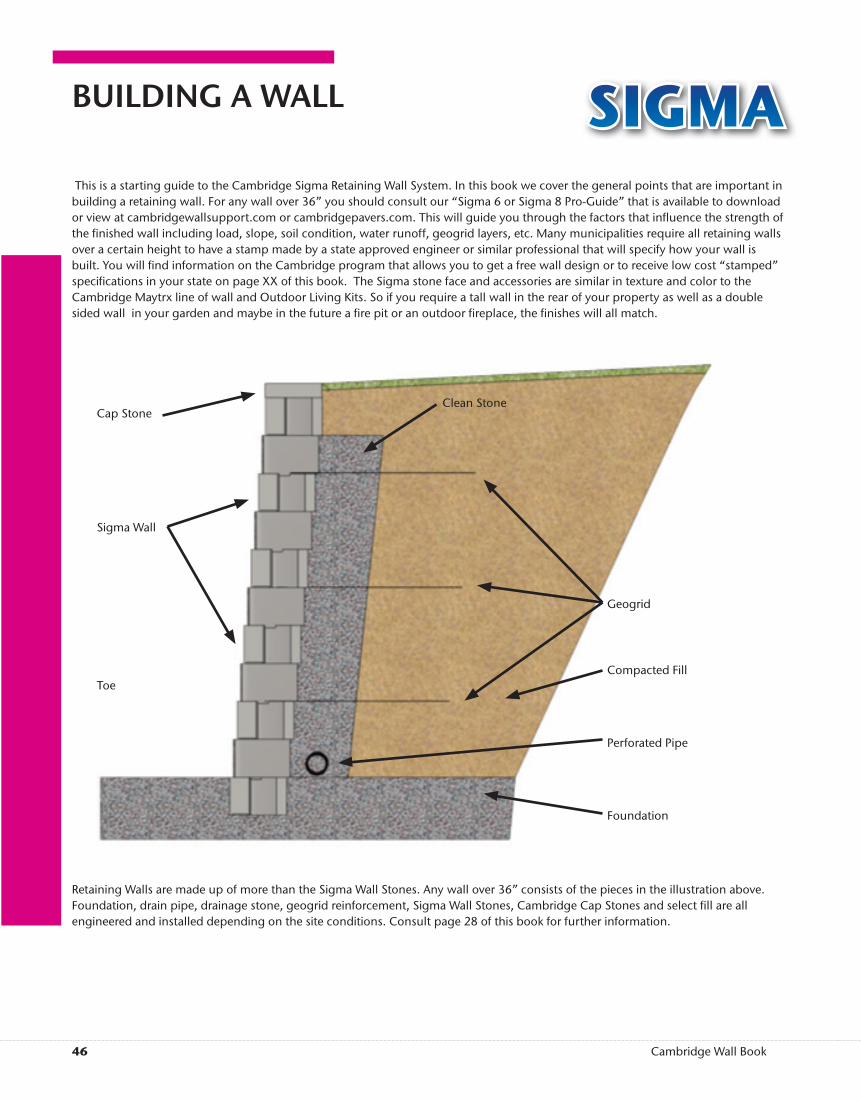
BUILDING A WALL SIGMA This is a starting guide to the Cambridge Sigma Retaining Wall System. In this book we cover the general points that are important in building a retaining wall. For any wall over 36” you should consult our “Sigma 6 or Sigma 8 Pro-Guide” that is available to download or view at cambridgewallsupport.com or cambridgepavers.com. This will guide you through the factors that in� uence the strength of the � nished wall including load, slope, soil condition, water runoff, geogrid layers, etc. Many municipalities require all retaining walls over a certain height to have a stamp made by a state approved engineer or similar professional that will specify how your wall is built. You will � nd information on the Cambridge program that allows you to get a free wall design or to receive low cost “stamped” speci� cations in your state on page XX of this book. The Sigma stone face and accessories are similar in texture and color to the Cambridge Maytrx line of wall and Outdoor Living Kits. So if you require a tall wall in the rear of your property as well as a double sided wall in your garden and maybe in the future a � re pit or an outdoor � replace, the � nishes will all match.
Retaining Walls are made up of more than the Sigma Wall Stones. Any wall over 36” consists of the pieces in the illustration above. Foundation, drain pipe, drainage stone, geogrid reinforcement, Sigma Wall Stones, Cambridge Cap Stones and select � ll are all engineered and installed depending on the site conditions. Consult page 28 of this book for further information.
Cap Stone
Sigma Wall
Toe
Foundation
Perforated Pipe
Compacted Fill
Geogrid
Clean Stone

46 47Cambridge Wall Book
SIGMA

48 49Cambridge Wall Book
SIGMA WALL

48 49Cambridge Wall Book
Sigma 8 Wall and Steps with Cambridge Large Caps as Treads
13” Double Sided Caps above Wall
(right)
Sigma 8 Wall and Steps with Cambridge 13” Double Sided Caps
above Wall
(left)
SIGMA WALL

50 51Cambridge Wall Book
SIGMAKNOBS
Set all wallstones with knobs protruding down, so that one knob will drop into each core of the wallstone below establishing a bond. Pull the wallstones forward and center on the bond of the two wallstones below. All full-on bond wallstones are set in this way. Corners and cutting a wallstone for adjustment are discussed in the corner section of this handbook titled: Sigma 6 OR 8 Inch Corner.
The Sigma 6-Inch has 4 knobs protruding from the top of the wallstone. These knobs are used for alignment of setback and for holding the geogrid in place when it is pulled tight. They are not part of the engineering strength of the wall system. The long textured face is the front of the wallstone and the knobs closest to the front are used to set the wallstone for 6 degrees. If the wall is designed as a 6-degree setback, then no changes to the knobs are required. If the wall desired is to be almost vertical, you will need to remove the two knobs closest to the front face.
SIGMA 8 WALL STONE
DIMENSIONS 8” H x 18” W x 12” D
SIGMA 8 CORNER UNIT
DIMENSIONS 8” H x 14” W x 8” D
CAMBRIDGE SIGMA 6 WALL STONE
DIMENSIONS 6” H x 16” W x 12” D
CAMBRIDGE SIGMA 6 CORNER UNIT
DIMENSIONS 6” H x 14” W x 8” D
CAMBRIDGE LARGE CAP
DIMENSIONS 3” H x 18” W x 12” D
CAMBRIDGE 13” DOUBLE-SIDED CAP
DIMENSIONS 3” H x 12” W x 13” D

50 51Cambridge Wall Book
SIGMA Downloads
Including:• Sigma 6 and 8 Setback
• Sigma 6 Near Vertical
• Base preparation
• Geogrid tables
• And Many More
INSTALL GUIDES12 PAGES, 3 BOOKS
SIGMA WALL HOW-TOAll the Detail you need to build Sigma Wall are located in the “Designscape” Pages in the rear of this book.

52 53Cambridge Wall Book
SIGMA WALL

52 53Cambridge Wall Book
SIGMA WALL

54 55Cambridge Wall Book
SIGMA WALL

54 55Cambridge Wall Book
SIGMA WALL

56 57Cambridge Wall Book
SIGMA WALL

56 57Cambridge Wall Book
SIGMA WALL
58 59Cambridge Wall Book
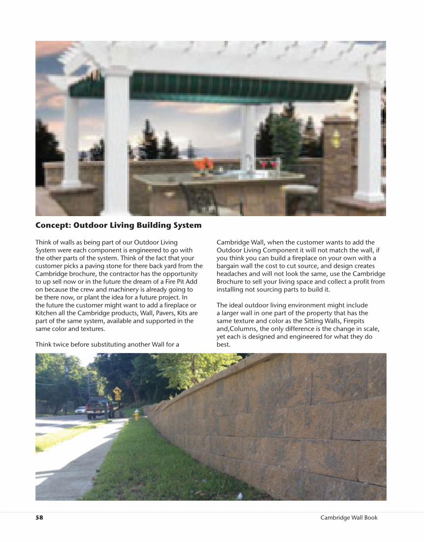
Concept: Outdoor Living Building System
Think of walls as being part of our Outdoor Living System were each component is engineered to go with the other parts of the system. Think of the fact that your customer picks a paving stone for there back yard from the Cambridge brochure, the contractor has the opportunity to up sell now or in the future the dream of a Fire Pit Add on because the crew and machinery is already going to be there now, or plant the idea for a future project. In the future the customer might want to add a � replace or Kitchen all the Cambridge products, Wall, Pavers, Kits are part of the same system, available and supported in the same color and textures.
Think twice before substituting another Wall for a
Cambridge Wall, when the customer wants to add the Outdoor Living Component it will not match the wall, if you think you can build a � replace on your own with a bargain wall the cost to cut source, and design creates headaches and will not look the same, use the Cambridge Brochure to sell your living space and collect a pro� t from installing not sourcing parts to build it.
The ideal outdoor living environment might include a larger wall in one part of the property that has the same texture and color as the Sitting Walls, Firepits and,Columns, the only difference is the change in scale, yet each is designed and engineered for what they do best.

58 59Cambridge Wall Book
SIGMA WALL

60 61Cambridge Wall Book
Set all wallstones with knobs protruding down, so that one knob will drop into each core of the wallstone below establishing a bond. Pull the wallstones forward and center on the bond of the two wallstones below. All full-on bond wallstones are set in this
way. Corners and cutting a wallstone for adjustment are discussed in the corner section of this handbook titled:Sigma 6-Inch Corner. Geogrid LayersPlace the geogrid over the layer of Sigma 6-Inch Wallstones, 3/4-inch drainage stone and the select � ll that is designated. Maintain the
correct orientation designated by the geogrid manufacturer.
Place the next layer of Sigma 6-Inch wallstones. Be certain that the geogrid openings are hooked by the Sigma
6-Inch knobs and � ll the cavities with 3/4-inch clean stone. Pull the geogrid tight and place stakes to hold it taught after � lling the cores.
Do not drive heavy equipmentdirectly on the exposed geogrid.
Place the drainage stone and control � ll for that layer and compact. Use only lightweight compaction equipment within 3 feet of the back of the Sigma 6-Inch Wall. Place material and compact on every layer in 3-inch lifts. Sweep the top of the wallstones so they are clean before adding the next layer.
Curved WallsThe Sigma 6-Inch Wall System allows for a very tight inside radius.
Although the knobs might not provide a gauge for setback, this can be established visually. Lock the geogrid and the wallstones by � lling the cores and compacting on every layer. It is simple to remove a knob if it is in the way of the desired radius.
Following LayersThe next layers repeat the orientation of the � rst or second layer. Follow these directions. For walls higher than 36 inches, refer to your engineer’s design.
Sigma 6-Inch wallstones can be set almost vertical (1.6-degree batter) as well as set back (for additional strength) at a 6-degree batter. These instructions cover the almost vertical and the setback features of the wallstone and use of the knobs on the wallstone. The corner and adjustment wallstone for the corner instructions are available in another section of this book titled Sigma 6-Inch Corner.
KnobsThe Sigma 6-Inch has 4 knobs protruding from the top of the wallstone. These knobs are used for alignment of setback and for
holding the geogrid in place when it is pulled tight. They are not part of the engineering strength of the wall system. The long textured face is the front of the wallstone and the knobs closest to the front are used to set the wallstone for 6 degrees. If the wall is designed as
a 6-degree setback, then no changes to the knobs are required. If the wall desired is to be almost vertical, you will need to remove the two knobs closest to the front face.
The knobs can be removed with a hammer and chisel. Be sure no part of the knob is protruding past the top surface of the wallstone. See Figure 2. First LayerThe Sigma 6-Inch wallstones are all set with the knobs positioned down. While laying the � rst course on the base, either remove the
knobs or tap the wallstones into the base to insure all wallstones are level and plumb. To keep the wall straight, use a string line along the back of the wallstones on the � rst layer. The � rst layer is the most important part of the wall. It is the easiest place to adjust for height. All additional layers will use the � rst layer to
establish overall levelness and the heights of all wallstones. Note: Bury the � rst layer at least 1 inch below � nished grade for every foot of wall height. Following the base guidelines (refer to page 5 in this book), a 4-inch perforated drainpipe needs to be installed behind the � rst layer to carry water away from the wall. For every layer, place 3/4 of an inch of clean crushed stone 12 inches behind the wall. Use the 3/4-inch clean stone for core � ll. The core should be � lled to 3/4 of an inch from the top of the wallstone. Place the correct back� ll soil as advised by the engineer and compact in 3-inch lifts. Use only lightweight compaction equipment within 3 feet of the back of the wall. Sweep the top of the wallstones, so they are clean before adding the next layer.
Second LayerIf you are creating an almost vertical 1.6-degree wall, remove the two knobs closest to the face of the wallstone for all additional wallstones used. If you desire the 6-degree setback, the knobs are already correct as the wallstones are shipped. The wallstones will be set with knobs protruding down.
Front Knobs6 Degrees
Front
If BuildingAlmost VerticalThen Remove
The Front Knobs
Knobs DownInto Core Below
Cambridge Wall Products SIGMA
Figure 1
Figure 3
Figure 2
Figure 4
Installation Instructions:Sigma 6-Inch Vertical Or Setback Wall
Figure 5
Figure 7
Figure 8
Figure 9
Figure 11
Figure 10
Figure 6
Lightly Stake Geogrid
Fill Cores Over Geogrid
Controlled Fill
Stone Drainage Layer
Crushed StoneDrainage Area

60 61Cambridge Wall Book
SIGMA
Knob SideOf Wallstone String Line
14 5/8
Measure ForAdjustment
WallstoneShown is a Cambridge Sigma 6-Inch raised patio retaining wall in the full setback con� guration with Cambridge Large Caps. The Sigma 6-Inch Wallstones can be set almost vertically (1.6 degree) as well as full setback (6 degrees) for additional strength. These instructions cover the following: The corner structure and the adjustment wallstone for bond as the wall is built higher on each layer and adding cap stones.
First LayerSet the corner � rst if it is used in the design, and then set a full wallstone starting from the long face of the corner. Cambridge Sigma
6-Inch Wallstones are set knobs down. Tap the wallstones into the base with a rubber mallet. Use a line on the rear of the wallstones to guide each stone in the layer to be
level and plumb (remove the knobs for the � rst layer if the base is too hard). It is critical to be level in all directions on the � rst layer. This is the only layer where adjustment is simple. See Figure 1.
IMPORTANT STEP:In the � rst layer, full wallstones are set next to the long face of the Sigma 6-Inch Corner Wallstone. The wallstone next to the small face of the corner is cut to 14 inches plus the setback for a wall that is 14 5/8 inches. For an almost vertical con� guration, this stone is cut to 14 3/16 inches. This cut allows full wallstones to be cut as the sides adjust in from the setback, eliminating “slivers”. Cut the edge of the adjustment wallstone closest to the corner normally or away from the line of sight so it is not noticeable. If you are using the Renaissance texture, tap the cut edge lightly with a hammer. See Figure 2.
After setting the cut wallstone next to the small face of the corner, continue the � rst row using the rear of the wallstones as a guide along with a straight edge or string line. See Figure 3.
Second LayerTo begin the second layer, position the corner as shown in Figure 4. Set the corner in position (5/8 of an inch for a full setback wall or 3/16 of an inch for an almost vertical wall), in from the two face sides for a 7-degree batter (setback) or 1.6-degree batter (almost vertical).
Adding The Full Wallstones Set the second layer over the � rst layer, knobs down (following wall installation instructions). Place a full wallstone over the middle of the two wallstones in the layer below. Line up the knob in the open
cavities of the two wallstones below and then pull the wallstone forward toward the front face. Recheck to be sure that bond is maintained. Install all full wallstones using this method.
Figure 4
Installation Instructions:Sigma 6-Inch WallCorner Options
Measure Adjustment Wallstones Once the wallstones have been set for the second layer, the distance remaining between the last full wallstone in each direction and the corner will be the only cuts needed. These are called adjustment wallstones. The second layer will only require one adjustment wallstone. After this layer, adjustment wallstones will be cut on each side of the corner.
Cut Adjustment WallstoneMark and cut the length of the wallstone needed to � ll in next to the corner with a masonry saw.
Note: Never cut the corner wallstone. • If the area for the adjustment wallstone is
too small, create two wallstone cuts next to each other. • Place the “cut” side of the wallstone away from line of sight — similar
to best practice in handling the seam when installing vinyl siding. If a knob section will overlap the corner wallstone below, remove those knobs with a hammer and secure with retaining wall adhesive.
Placing the Adjustment WallstoneMaintain alignment and apply retaining wall adhesive.
General Information• Level and use a string line to keep the
wall straight.• Use the line on the rear of the wallstones to • guide each layer. If installing on concrete, remove the knobs on the
� rst layer with a hammer and chisel. • To set the embedment, place and compact soil in front of
the wallstones. • Go to www.cambridgepavers.com or consult your Cambridge
Territory Manager for the correct procedures in building an engineered retaining wall.
Repeat LayersThe next layer repeats the orientation of the corner on the � rst layer.
Note: Because the wall is setback, the distance to the corner from a full wallstone gets smaller as the wall gets higher. To allow for this, the wall is adjusted in 5/8 of an inch or 3/16 of an inch from each side for each layer. The adjustment wallstone length will change on every layer to allocate for this. The different lengths represent the amount of setback for full setback or almost vertical
con� gurations.
CapMaytRx 6 retaining walls use the Cambridge Large Cap (3-inches high x 12-inches deep x 18-inches wide). See Figure 8. Make a corner
cap by splitting 2 inches from the end of a cap and use that wallstone as the corner. If the wall will be retaining soil to the top or is being used for a raised patio, the cap can be pulled forward 1 inch to create a reveal. If the caps are above ground in the back of the wall, the Cambridge 13-inch Double-
Sided Cap (3-inches high x 13-inches deep x 12-inches wide) can be used.
The Sigma 6-Inch wallstone features an emergency corner option — one wallstone will yield two (stub) corners in the � eld for short landscape walls.
Figure 4-A
Figure 4-B
Figure 1
Figure 2
Figure 3
Figure 5
Figure 6
Figure 7
Figure 8
62 63Cambridge Wall Book
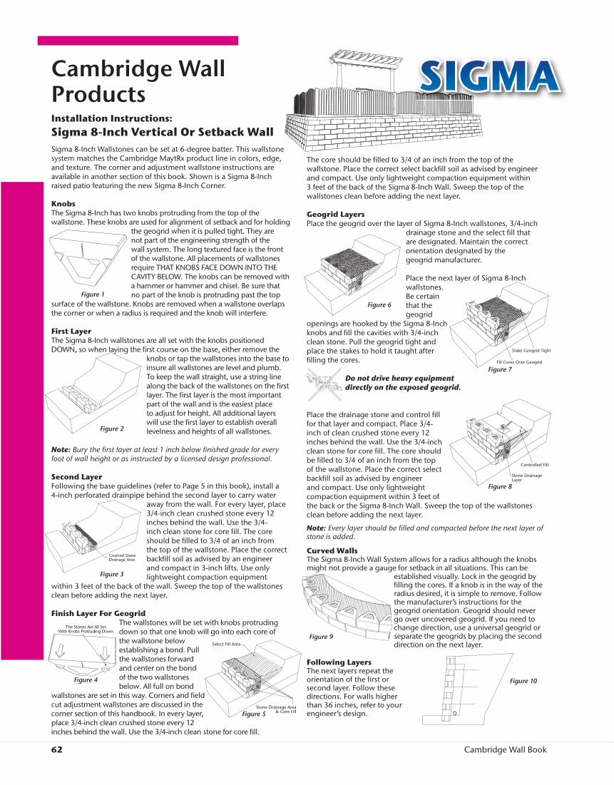
The core should be � lled to 3/4 of an inch from the top of the wallstone. Place the correct select back� ll soil as advised by engineer and compact. Use only lightweight compaction equipment within 3 feet of the back of the Sigma 8-Inch Wall. Sweep the top of the wallstones clean before adding the next layer.
Geogrid LayersPlace the geogrid over the layer of Sigma 8-Inch wallstones, 3/4-inch
drainage stone and the select � ll that are designated. Maintain the correct orientation designated by thegeogrid manufacturer.
Place the next layer of Sigma 8-Inch wallstones. Be certain that the geogrid
openings are hooked by the Sigma 8-Inch knobs and � ll the cavities with 3/4-inch clean stone. Pull the geogrid tight and place the stakes to hold it taught after � lling the cores.
Do not drive heavy equipmentdirectly on the exposed geogrid.
Place the drainage stone and control � ll for that layer and compact. Place 3/4-inch of clean crushed stone every 12 inches behind the wall. Use the 3/4-inch clean stone for core � ll. The core should be � lled to 3/4 of an inch from the top of the wallstone. Place the correct select back� ll soil as advised by engineer and compact. Use only lightweight compaction equipment within 3 feet of the back or the Sigma 8-Inch Wall. Sweep the top of the wallstones clean before adding the next layer.
Note: Every layer should be � lled and compacted before the next layer of stone is added.
Curved WallsThe Sigma 8-Inch Wall System allows for a radius although the knobs might not provide a gauge for setback in all situations. This can be
established visually. Lock in the geogrid by � lling the cores. If a knob is in the way of the radius desired, it is simple to remove. Follow the manufacturer’s instructions for the geogrid orientation. Geogrid should never go over uncovered geogrid. If you need to change direction, use a universal geogrid or separate the geogrids by placing the second direction on the next layer.
Following LayersThe next layers repeat the orientation of the � rst or second layer. Follow these directions. For walls higher than 36 inches, refer to your engineer’s design.
Cambridge Wall Products SIGMAInstallation Instructions:Sigma 8-Inch Vertical Or Setback WallSigma 8-Inch Wallstones can be set at 6-degree batter. This wallstone system matches the Cambridge MaytRx product line in colors, edge, and texture. The corner and adjustment wallstone instructions are available in another section of this book. Shown is a Sigma 8-Inch raised patio featuring the new Sigma 8-Inch Corner.
KnobsThe Sigma 8-Inch has two knobs protruding from the top of the wallstone. These knobs are used for alignment of setback and for holding
the geogrid when it is pulled tight. They are not part of the engineering strength of the wall system. The long textured face is the front of the wallstone. All placements of wallstones require THAT KNOBS FACE DOWN INTO THE CAVITY BELOW. The knobs can be removed with a hammer or hammer and chisel. Be sure that no part of the knob is protruding past the top
surface of the wallstone. Knobs are removed when a wallstone overlaps the corner or when a radius is required and the knob will interfere.
First LayerThe Sigma 8-Inch wallstones are all set with the knobs positioned DOWN, so when laying the � rst course on the base, either remove the
knobs or tap the wallstones into the base to insure all wallstones are level and plumb. To keep the wall straight, use a string line along the back of the wallstones on the � rst layer. The � rst layer is the most important part of the wall and is the easiest place to adjust for height. All additional layers will use the � rst layer to establish overall levelness and heights of all wallstones.
Note: Bury the � rst layer at least 1 inch below � nished grade for every foot of wall height or as instructed by a licensed design professional.
Second LayerFollowing the base guidelines (refer to Page 5 in this book), install a 4-inch perforated drainpipe behind the second layer to carry water
away from the wall. For every layer, place 3/4-inch clean crushed stone every 12 inches behind the wall. Use the 3/4-inch clean stone for core � ll. The core should be � lled to 3/4 of an inch from the top of the wallstone. Place the correct back� ll soil as advised by an engineer and compact in 3-inch lifts. Use only lightweight compaction equipment
within 3 feet of the back of the wall. Sweep the top of the wallstones clean before adding the next layer.
Finish Layer For GeogridThe wallstones will be set with knobs protruding down so that one knob will go into each core of the wallstone below establishing a bond. Pull the wallstones forward and center on the bond of the two wallstones below. All full on bond
wallstones are set in this way. Corners and � eld cut adjustment wallstones are discussed in the corner section of this handbook. In every layer, place 3/4-inch clean crushed stone every 12 inches behind the wall. Use the 3/4-inch clean stone for core � ll.
Stake Geogrid Tight
Fill Cores Over Geogrid
The Stones Are All SetWith Knobs Protruding Down
Select Fill Area
Stone Drainage Area& Core Fill
Controlled Fill
Stone DrainageLayer
Crushed StoneDrainage Area
Figure 10
Figure 1
Figure 4
Figure 6
Figure 8
Figure 9
Figure 5
Figure 2
Figure 3
Figure 7
62 63Cambridge Wall Book
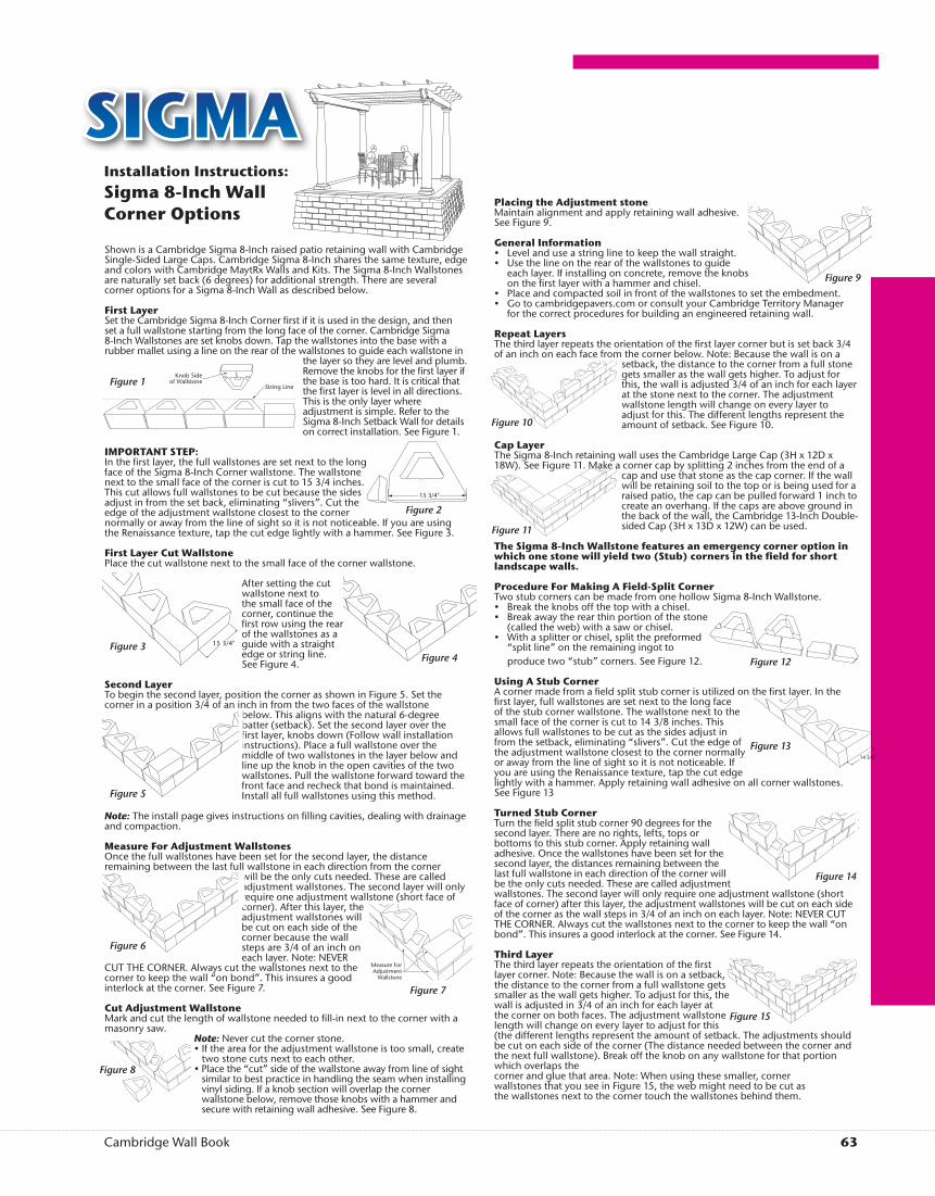
Shown is a Cambridge Sigma 8-Inch raised patio retaining wall with Cambridge Single-Sided Large Caps. Cambridge Sigma 8-Inch shares the same texture, edge and colors with Cambridge MaytRx Walls and Kits. The Sigma 8-Inch Wallstones are naturally set back (6 degrees) for additional strength. There are several corner options for a Sigma 8-Inch Wall as described below.
First LayerSet the Cambridge Sigma 8-Inch Corner � rst if it is used in the design, and then set a full wallstone starting from the long face of the corner. Cambridge Sigma 8-Inch Wallstones are set knobs down. Tap the wallstones into the base with a rubber mallet using a line on the rear of the wallstones to guide each wallstone in
the layer so they are level and plumb. Remove the knobs for the � rst layer if the base is too hard. It is critical that the � rst layer is level in all directions. This is the only layer where adjustment is simple. Refer to the Sigma 8-Inch Setback Wall for details on correct installation. See Figure 1.
IMPORTANT STEP:In the � rst layer, the full wallstones are set next to the long face of the Sigma 8-Inch Corner wallstone. The wallstone next to the small face of the corner is cut to 15 3/4 inches. This cut allows full wallstones to be cut because the sides adjust in from the set back, eliminating “slivers”. Cut the edge of the adjustment wallstone closest to the corner normally or away from the line of sight so it is not noticeable. If you are using the Renaissance texture, tap the cut edge lightly with a hammer. See Figure 3.
First Layer Cut WallstonePlace the cut wallstone next to the small face of the corner wallstone.
After setting the cut wallstone next to the small face of the corner, continue the � rst row using the rear of the wallstones as a guide with a straight edge or string line. See Figure 4.
Second LayerTo begin the second layer, position the corner as shown in Figure 5. Set the corner in a position 3/4 of an inch in from the two faces of the wallstone
below. This aligns with the natural 6-degree batter (setback). Set the second layer over the � rst layer, knobs down (Follow wall installation instructions). Place a full wallstone over the middle of two wallstones in the layer below and line up the knob in the open cavities of the two wallstones. Pull the wallstone forward toward the front face and recheck that bond is maintained. Install all full wallstones using this method.
Note: The install page gives instructions on � lling cavities, dealing with drainage and compaction.
Measure For Adjustment Wallstones Once the full wallstones have been set for the second layer, the distance remaining between the last full wallstone in each direction from the corner
will be the only cuts needed. These are called adjustment wallstones. The second layer will only require one adjustment wallstone (short face of corner). After this layer, the adjustment wallstones will be cut on each side of the corner because the wall steps are 3/4 of an inch on each layer. Note: NEVER
CUT THE CORNER. Always cut the wallstones next to the corner to keep the wall “on bond”. This insures a good interlock at the corner. See Figure 7.
Cut Adjustment WallstoneMark and cut the length of wallstone needed to � ll-in next to the corner with a masonry saw.
Note: Never cut the corner stone. • If the area for the adjustment wallstone is too small, create
two stone cuts next to each other. • Place the “cut” side of the wallstone away from line of sight
similar to best practice in handling the seam when installing vinyl siding. If a knob section will overlap the corner wallstone below, remove those knobs with a hammer and secure with retaining wall adhesive. See Figure 8.
Placing the Adjustment stoneMaintain alignment and apply retaining wall adhesive. See Figure 9.
General Information• Level and use a string line to keep the wall straight.• Use the line on the rear of the wallstones to guide
each layer. If installing on concrete, remove the knobs on the � rst layer with a hammer and chisel.
• Place and compacted soil in front of the wallstones to set the embedment. • Go to cambridgepavers.com or consult your Cambridge Territory Manager
for the correct procedures for building an engineered retaining wall.
Repeat LayersThe third layer repeats the orientation of the � rst layer corner but is set back 3/4 of an inch on each face from the corner below. Note: Because the wall is on a
setback, the distance to the corner from a full stone gets smaller as the wall gets higher. To adjust for this, the wall is adjusted 3/4 of an inch for each layer at the stone next to the corner. The adjustment wallstone length will change on every layer to adjust for this. The different lengths represent the amount of setback. See Figure 10.
Cap LayerThe Sigma 8-Inch retaining wall uses the Cambridge Large Cap (3H x 12D x 18W). See Figure 11. Make a corner cap by splitting 2 inches from the end of a
cap and use that stone as the cap corner. If the wall will be retaining soil to the top or is being used for a raised patio, the cap can be pulled forward 1 inch to create an overhang. If the caps are above ground in the back of the wall, the Cambridge 13-Inch Double-sided Cap (3H x 13D x 12W) can be used.
The Sigma 8-Inch Wallstone features an emergency corner option in which one stone will yield two (Stub) corners in the � eld for short landscape walls.
Procedure For Making A Field-Split CornerTwo stub corners can be made from one hollow Sigma 8-Inch Wallstone. • Break the knobs off the top with a chisel. • Break away the rear thin portion of the stone
(called the web) with a saw or chisel. • With a splitter or chisel, split the preformed
“split line” on the remaining ingot to produce two “stub” corners. See Figure 12.
Using A Stub CornerA corner made from a � eld split stub corner is utilized on the � rst layer. In the � rst layer, full wallstones are set next to the long face of the stub corner wallstone. The wallstone next to the small face of the corner is cut to 14 3/8 inches. This allows full wallstones to be cut as the sides adjust in from the setback, eliminating “slivers”. Cut the edge of the adjustment wallstone closest to the corner normally or away from the line of sight so it is not noticeable. If you are using the Renaissance texture, tap the cut edge lightly with a hammer. Apply retaining wall adhesive on all corner wallstones. See Figure 13
Turned Stub CornerTurn the � eld split stub corner 90 degrees for the second layer. There are no rights, lefts, tops or bottoms to this stub corner. Apply retaining wall adhesive. Once the wallstones have been set for the second layer, the distances remaining between the last full wallstone in each direction of the corner will be the only cuts needed. These are called adjustment wallstones. The second layer will only require one adjustment wallstone (short face of corner) after this layer, the adjustment wallstones will be cut on each side of the corner as the wall steps in 3/4 of an inch on each layer. Note: NEVER CUT THE CORNER. Always cut the wallstones next to the corner to keep the wall “on bond”. This insures a good interlock at the corner. See Figure 14.
Third LayerThe third layer repeats the orientation of the � rst layer corner. Note: Because the wall is on a setback, the distance to the corner from a full wallstone gets smaller as the wall gets higher. To adjust for this, the wall is adjusted in 3/4 of an inch for each layer at the corner on both faces. The adjustment wallstone length will change on every layer to adjust for this (the different lengths represent the amount of setback. The adjustments should be cut on each side of the corner (The distance needed between the corner and the next full wallstone). Break off the knob on any wallstone for that portion which overlaps the corner and glue that area. Note: When using these smaller, corner wallstones that you see in Figure 15, the web might need to be cut as the wallstones next to the corner touch the wallstones behind them.
SIGMAInstallation Instructions:Sigma 8-Inch WallCorner Options
Knob Sideof Wallstone
String LineFigure 1
15 3/4"Figure 3
Figure 5
Figure 6
15 3/4"
Figure 2
Figure 4
Figure 9
Figure 12
Figure 10
Figure 11
14 3/8"
Figure 13
Figure 14
Figure 15
Measure ForAdjustment
Wallstone
Figure 7
Figure 8